1
User’s Manual Scan'O'Vision STAR Software 3434.501.02 Version 1.8 Edition November 2012 CAUTION This program may be modified at any time without prior notification. The information contained within this document may be modified without warning. Swiss Timing LTD cannot be held responsible for errors within this document nor for any subsequent nor consequential damages (including loss of profit) arising from its provision, nor performance or use of products described herein, which will be covered by another guarantee, contract or other legal document. New functions are indicated with this logo: (the first software version including this function is indicated under the NEW) This manual is based on the Scan'O'Vision software version 01.009.001.048. For the latest information, please check the ReadMe.txt file delivered with the latest upgrade. TABLE OF CONTENTS 1 INTRODUCTION .............................................................................. 1 1.1 1.2 1.3 2 SOFTWARE DESCRIPTION ............................................................ 3 2.1 2.2 2.3 2.4 2.5 2.6 2.7 2.8 2.9 3 DEFINITIONS ............................................................................................................... 1 STARTING THE SOFTWARE ......................................................................................... 2 DURATION OF A RACE ................................................................................................. 2 MAIN SCREEN ............................................................................................................. 3 RACE TITLE ................................................................................................................. 3 MENU .......................................................................................................................... 3 MODE SELECTION ....................................................................................................... 4 MAIN WINDOW ............................................................................................................ 4 FUNCTION WINDOW .................................................................................................... 5 ZOOM WINDOW ........................................................................................................... 5 THUMBNAIL WINDOW .................................................................................................. 5 STATUS BAR ............................................................................................................... 7 USE OF THE SOFTWARE ............................................................... 8 3.1 LANGUAGE SELECTION ............................................................................................... 8 3.2 CAMERA SETTING AND ALIGNMENT ............................................................................ 8 3.2.1 First adjustment ................................................................................................... 8 3.2.2 Camera alignment ............................................................................................... 9 3.2.3 Final adjustment................................................................................................. 12 3.3 SYNCHRONISATION AND CONFIGURATION OF THE SYSTEM ..................................... 12 3.4 ZERO TEST................................................................................................................ 13 3.5 RECORDING A RACE ................................................................................................. 14 3.6 JUDGING A RACE....................................................................................................... 15 4 FUNCTIONS DESCRIPTION .......................................................... 16 4.1 CONFIGURATION MODE ........................................................................................ 16 4.1.1 Hardware setup tab ...................................................................................... 16 4.1.2 Software setup tab ......................................................................................... 16 4.1.3 Print setup tab ............................................................................................... 18 4.1.4 Export setup tab ................................................................................................. 19 4.2 RACE MODE ......................................................................................................... 23 4.2.1 Start a race (shortcut: Ctrl + G) .................................................................. 23 4.2.2 Continue the race .......................................................................................... 23 4.2.3 New race (shortcut: Ctrl + N) ........................................................................... 23 4.2.4 Load a race ................................................................................................... 23 4.2.5 Copy a race (Save as) ................................................................................ 24 4.2.6 Save race parameters ................................................................................. 24 4.2.7 Delete a race ................................................................................................. 24 4.2.8 Enable / Disable lane numbering........................................................... 24 4.2.9 Synchronisation ............................................................................................ 24 4.2.10 Test function .............................................................................................. 25 © Reproduction in any manner whatsoever without the written permission of Swiss Timing Ltd. is strictly forbidden. © La reproduction de ce document, sous quelque forme que ce soit, et sans l‟autorisation écrite de Swiss Timing Ltd., est strictement interdite. © Die Vervielfältigung oder Wiedergabe in jeglicher Weise ist ohne schriftliche Genehmigung von Swiss Timing Ltd. strengstens untersagt. SWISS TIMING LTD P.O. Box 138, rue de l'Envers 1 2606 Corgémont, Switzerland www.swisstiming.com Phone +41 32 488 36 11 Fax +41 32 488 36 09 [email protected] 4.2.11 / , Semi-automatic crop ................................................................... 25 4.2.12 / Black & white image display ................................ 25 4.2.13 Existing races tab (shortcut: Ctrl + O) ................................................... 25 4.2.14 Parameters tab ......................................................................................... 26 4.2.15 Race header tab ....................................................................................... 27 4.2.16 Modify start time (shortcut: Ctrl + M) .......................................................... 27 4.2.17 Units / Rules tab ....................................................................................... 29 4.2.18 Preferences 1 tab ..................................................................................... 29 4.2.19 Preferences 2 tab .......................................................................................... 30 4.3 ACQUISITION MODE .................................................................................................. 32 4.3.1 Status of the race............................................................................................... 32 4.3.2 Thumbnail in acquisition mode ........................................................................ 33 4.3.3 Functions in acquisition mode ......................................................................... 33 4.3.4 Start type ............................................................................................................. 34 4.3.5 Time trial ............................................................................................................. 35 4.4 JUDGMENT MODE ................................................................................................. 37 4.4.1 Time mark ........................................................................................................... 37 4.4.2 Load a race ................................................................................................... 37 4.4.3 Delete a race ................................................................................................. 37 4.4.4 Enable / Disable lane numbering........................................................... 37 4.4.5 Colour of time marks ............................................................................. 38 4.4.6 Mask/Display time marks during judgment (shortcut: F7) ........................... 38 4.4.7 / Fast Open (shortcut: Ctrl + F) .............................................................. 38 4.4.8 / Active Link and / Active Link+ ...................................................... 38 4.4.9 / Show only local time marks or all ......................................................... 38 4.4.10 / Active/suspend the data handling output (shortcut: Ctrl + F12) .. 38 4.4.11 / Black & white image display ................................ 39 4.4.12 Results window .............................................................................................. 39 4.4.13 Delete a time mark ........................................................................................ 39 4.4.14 Modify a time mark ........................................................................................ 39 4.4.15 Modify the start list......................................................................................... 40 4.4.16 Reaction time ................................................................................................. 40 4.4.17 Competitor status........................................................................................... 40 4.4.18 Existing races tab ..................................................................................... 40 4.4.19 Parameters tab ......................................................................................... 40 4.4.20 Header tab ................................................................................................. 41 4.4.21 Precision tab ............................................................................................. 41 4.4.22 Identification tab ........................................................................................ 41 4.4.23 Palette tab (shortcut: Ctrl + R) ................................................................ 41 4.4.24 Search tab (shortcut: Ctrl + H)................................................................ 42 4.4.25 Time tab ..................................................................................................... 42 4.5 CAMERA SETTING MODE (SHORTCUT: CTRL + J)................................................ 43 4.5.1 Horizontal references ................................................................................... 43 4.5.2 Colour of reference lines .................................................................................. 44 4.5.3 Online zoom .................................................................................................. 44 4.5.4 Matrix mode ................................................................................................... 45 4.5.5 Light flickering ............................................................................................... 45 © Reproduction in any manner whatsoever without the written permission of Swiss Timing Ltd. is strictly forbidden. © La reproduction de ce document, sous quelque forme que ce soit, et sans l‟autorisation écrite de Swiss Timing Ltd., est strictement interdite. © Die Vervielfältigung oder Wiedergabe in jeglicher Weise ist ohne schriftliche Genehmigung von Swiss Timing Ltd. strengstens untersagt. SWISS TIMING LTD P.O. Box 138, rue de l'Envers 1 2606 Corgémont, Switzerland www.swisstiming.com Phone +41 32 488 36 11 Fax +41 32 488 36 09 [email protected] 4.5.6 Automatic light adjustment .......................................................................... 45 4.5.7 Detection zone for the automatic recording by camera ............................... 46 4.5.8 Sharpness adjustment ...................................................................................... 46 4.5.9 Camera setup tab ......................................................................................... 47 4.5.10 Image quality tab ....................................................................................... 48 4.5.11 Lens remote tab ........................................................................................ 48 4.5.12 Detection sensitivity tab .......................................................................... 49 4.5.13 Motorized support tab ................................................................................... 49 4.6 I/O SETTING MODE ............................................................................................... 50 4.6.1 IO Settings tab ................................................................................................... 50 4.6.2 Scoreboards ....................................................................................................... 51 4.6.3 Wind Gauge........................................................................................................ 53 4.6.4 False Start........................................................................................................... 53 4.6.5 Data Handling..................................................................................................... 53 4.6.6 IO Test tab .......................................................................................................... 54 4.7 FULL SCREEN MODE ................................................................................................. 55 4.8 WEB MODE .............................................................................................................. 57 4.9 OTHER FUNCTIONS ................................................................................................... 59 4.9.1 Crop ..................................................................................................................... 59 4.9.2 Modifying the acquisition speed ...................................................................... 61 4.9.3 Distances in horse lengths ............................................................................... 61 4.9.4 Kilometric reduction ........................................................................................... 64 4.9.5 Use of Active Link .............................................................................................. 64 4.9.6 Logo over the image ......................................................................................... 65 4.9.7 Judgment with transponder help ..................................................................... 65 4.9.8 Zoom training ..................................................................................................... 66 4.9.9 Sounds ................................................................................................................ 67 5 MENU DESCRIPTION .................................................................... 68 5.1 FILE MENU ................................................................................................................ 68 5.1.1 Hardware setup............................................................................................. 68 5.1.2 Software setup ............................................................................................... 68 5.1.3 Print (shortcut: Ctrl + P) ............................................................................... 68 5.1.4 Print Template 1 (shortcut: Ctrl + Shift + P) .................................................. 68 5.1.5 Print Template 2 (shortcut: Ctrl + Z) ............................................................... 68 5.1.6 Print setup ...................................................................................................... 68 5.1.7 Create PDF with Template 1 (shortcut: Ctrl + D) ......................................... 68 5.1.8 Create PDF with Template 2 (shortcut: Ctrl + Shift + D) ............................. 68 5.1.9 Export (shortcut: F8) .................................................................................... 69 5.1.10 Export full image (shortcut: Ctrl + F8) ................................................... 69 5.1.11 Export setup .............................................................................................. 69 5.1.12 Exit (shortcut: Alt + F4) ............................................................................ 69 5.2 RACE MENU .............................................................................................................. 69 5.2.1 New ................................................................................................................. 69 5.2.2 Existing races ................................................................................................ 69 5.2.3 Race parameters ......................................................................................... 69 5.2.4 Race header .................................................................................................. 69 © Reproduction in any manner whatsoever without the written permission of Swiss Timing Ltd. is strictly forbidden. © La reproduction de ce document, sous quelque forme que ce soit, et sans l‟autorisation écrite de Swiss Timing Ltd., est strictement interdite. © Die Vervielfältigung oder Wiedergabe in jeglicher Weise ist ohne schriftliche Genehmigung von Swiss Timing Ltd. strengstens untersagt. SWISS TIMING LTD P.O. Box 138, rue de l'Envers 1 2606 Corgémont, Switzerland www.swisstiming.com Phone +41 32 488 36 11 Fax +41 32 488 36 09 [email protected] 5.2.5 Units / Rules .................................................................................................. 69 5.2.6 Preferences 1 ................................................................................................ 69 5.2.7 Preferences 2 ............................................................................................... 69 5.2.8 Synchronisation ............................................................................................ 69 5.2.9 Test ................................................................................................................. 70 5.3 JUDGMENT ................................................................................................................ 70 5.3.1 Existing races ................................................................................................ 70 5.3.2 Parameters ................................................................................................... 70 5.3.3 Header............................................................................................................ 70 5.3.4 Precision ........................................................................................................ 70 5.3.5 Identification .................................................................................................. 70 5.3.6 Palette (shortcut: Ctrl + R) ........................................................................... 70 5.3.7 Search ............................................................................................................ 70 5.3.8 Time ................................................................................................................ 70 5.4 REGULATION MENU .................................................................................................. 70 5.4.1 Camera setup................................................................................................ 70 5.4.2 Image quality ................................................................................................. 70 5.4.3 Lens remote ................................................................................................... 70 5.5 SCOREBOARD MENU ................................................................................................. 71 5.5.1 Setup ................................................................................................................... 71 5.5.2 Send results (shortcut: Ctrl + F10) .................................................................. 71 5.5.3 Clear (shortcut: Ctrl + F2) ................................................................................. 71 5.5.4 Daytime (shortcut: Ctrl + F3)............................................................................ 71 5.5.5 End of judgment (shortcut: Ctrl + F9) ............................................................. 71 5.5.6 Automatic end of judgment .............................................................................. 71 5.6 LANGUAGE MENU ...................................................................................................... 71 5.7 HELP MENU ............................................................................................................... 71 5.7.1 About software version (shortcut: Ctrl + F1) .............................................. 71 5.7.2 About camera version .................................................................................. 71 5.7.3 Lens about ...................................................................................................... 71 6 SOFTWARE CONFIGURATION .................................................... 72 6.1 6.2 6.3 6.4 6.5 6.6 6.7 6.8 6.9 6.10 WORKING MODES ..................................................................................................... 72 MODE SETTING ......................................................................................................... 73 SPORT ...................................................................................................................... 73 ROUNDING REGULATION........................................................................................... 73 MANUAL START REGULATION ................................................................................... 74 UNITS ........................................................................................................................ 74 PRECISION ................................................................................................................ 74 SAVE ......................................................................................................................... 74 DOUBLE INSTANCE ................................................................................................... 75 NETWORKED COMPUTERS........................................................................................ 76 7 SOFTWARE TRANSLATION ......................................................... 77 8 PROTOCOLS ................................................................................. 78 8.1 DATA HANDLING ....................................................................................................... 78 8.1.1 Files [CONCAT & STARTLIST] ....................................................................... 78 8.1.2 HyTek Bidirectional ........................................................................................... 81 © Reproduction in any manner whatsoever without the written permission of Swiss Timing Ltd. is strictly forbidden. © La reproduction de ce document, sous quelque forme que ce soit, et sans l‟autorisation écrite de Swiss Timing Ltd., est strictement interdite. © Die Vervielfältigung oder Wiedergabe in jeglicher Weise ist ohne schriftliche Genehmigung von Swiss Timing Ltd. strengstens untersagt. SWISS TIMING LTD P.O. Box 138, rue de l'Envers 1 2606 Corgémont, Switzerland www.swisstiming.com Phone +41 32 488 36 11 Fax +41 32 488 36 09 [email protected] 8.1.3 OMEGA ............................................................................................................... 84 8.1.4 OMEGA (Suppl. Info) ........................................................................................ 86 9 KEYBOARD SHORCUTS .............................................................. 88 9 KEYBOARD SHORCUTS .............................................................. 88 © Reproduction in any manner whatsoever without the written permission of Swiss Timing Ltd. is strictly forbidden. © La reproduction de ce document, sous quelque forme que ce soit, et sans l‟autorisation écrite de Swiss Timing Ltd., est strictement interdite. © Die Vervielfältigung oder Wiedergabe in jeglicher Weise ist ohne schriftliche Genehmigung von Swiss Timing Ltd. strengstens untersagt. SWISS TIMING LTD P.O. Box 138, rue de l'Envers 1 2606 Corgémont, Switzerland www.swisstiming.com Phone +41 32 488 36 11 Fax +41 32 488 36 09 [email protected] 1 INTRODUCTION This manual explains the use of the software for the Scan'O'Vision ; for a general description of the whole system, please refer to the Main User's Manual of the Scan'O'Vison [3434.500 or 3434.505]. This manual is divided in 3 main parts: A general description of the software (chapter 2). How to use the system, in logical order (chapter 3). The description of all the functions (chapter 4). The software can be configured in different manner in order to block some rules, to do simultaneous judging and to run two instance of the software on the same computer; please refer to chapter 6 for these specific configurations. All the shortcut and specific mouse function can be found in chapter 9. 1.1 Definitions Currently, the Scan'O'Vision family includes the following models: : Black and white camera without matrix alignment (standard). : Colour camera without matrix alignment (compact). : Colour camera with remote control of the focus and aperture, without matrix alignment (compact). : Colour camera with matrix alignment (standard). : Colour camera with matrix alignment (compact). : Colour camera with matrix alignment and remote control of the focus and aperture of the lens (standard). : Colour camera with matrix alignment and remote control of the focus and aperture of the lens (compact). : Compact colour camera with matrix alignment and remote control of the focus and aperture of the lens for new lenses (for new lenses with electronic command of the focus). This manual applies to all models; the following icons are used to differences between models: This paragraph or chapter does not apply Scan'O'Vision . This paragraph or chapter does not apply Scan'O'Vision , nor This paragraph or chapter applies solely Scan'O'Vision . This paragraph or chapter applies solely Scan'O'Vision and . This paragraph or chapter applies solely Scan'O'Vision (camera with lens control). 3434.501.02 Version 1.8 indicate for the for the . for the for the for the and Page 1 The camera is typically supplied with a support permitting the setting of its position according to 4 axes. Here are the definitions used in this manual: Translation Pan Tilt Swivel Horizontal displacement, perpendicular to the finish line. Rotation in the horizontal plane. Rotation in the vertical plane, in the axis of the finish line. Rotation in the vertical plane, perpendicular to the finish line (to have the sensor "vertical" in the plan of the finish line). Other definitions or abbreviations: BIB DQ DNF DNS ID 1.2 Number identifying a competitor in the start list, used for the judgment. Disqualified Did Not Finish Did Not Start Identification of a race, a name (maximum 8 characters) used to identify the race on the hard disk of the computer. Starting the software To work with this manual, we are assuming that the installation and Windows configuration have been completed as described in the Scan'O'Vision STAR camera User’s Manual (document 3434.500 or 3434.505). The same Scan'O'Vision software can be used with or without a camera connected to the computer. When a camera is not connected to the computer, only viewing and judging images functions are available. The Scan'O'Vision software is started by launching the OSV7.EXE file on your computer or by a shortcut to this file; if a camera is connected, it will be automatically detected. If the camera was not connected to the computer or not powered when you start the OSV7.EXE software, it is automatically detected later when you connect it or power it. The camera and the software supports small Ethernet disconnection (<5s); in case of longer disconnection, the software will exit from “Camera Setting” mode and “Acquisition” mode. The corresponding function will again be available after the camera has been reconnected. 1.3 Duration of a race The maximum duration of a race (time between the start and the last recorded image) is between 24 and 48 hours. In facts the software allows only one "midnight" passage during a race. So if your race starts at 23h00 on day 1, you can record images until 23h59 on day 2 (so about 25h race duration); if your race starts at 1h00 in the morning of day 1, you can record images until 23h59 on day 2 (so about 47h of race duration). Note: this is not related to the image recording duration. For each race you can record images during at least 3 minutes, this limit increase when you reduce the acquisition speed. Page 2 Version 1.8 3434.501.02 2 SOFTWARE DESCRIPTION This chapter is a short description of the design and the main part of the software. 2.1 Main screen The screen is divided in different parts: 1. 2. 3. 4. 5. 6. 7. 8. Race title Menu Mode selection Main window Function window Zoom window Thumbnail window Status bar The different windows are separated by splitters. The position of splitters can be moved to resize the windows. There are limits in place to ensure usability. A. Main splitter B. Zoom splitter C. Thumbnail splitter 2.2 Race title When a race is open or in progress, the ID and the title of the race are displayed. 2.3 Menu The menu of the software allows you to access the functions. Typically it is not used, the icons and tabs in the function window being the preferred option. 3434.501.02 Version 1.8 Page 3 2.4 Mode selection The selection of a mode is done by clicking on an icon of this tool bar: Configuration mode Race mode Acquisition mode Judgment mode Camera setting mode I/O setting mode Enable thumbnail (Shortcut : F9) Disable thumbnail (Shortcut : Shift + F9) Full screen mode (Shortcut : F10) Web mode (Shortcut : Ctrl + W) For example, to select the kind of contact you have on the Start and Finish input. To visualize the races (without judgment) and record new races. The acquisition mode is a sub-mode of the race mode. It is used to record the image and is accessible by pressing the icon. To judge existing races. To set and align the camera on the finish line. Two sub-modes exist: o line scan mode (same image as during the acquisition). STAR 1x0 o matrix mode (video image to easily align the camera on the finish line). To configure and command some peripherals such as DH, scoreboards and wind meters. After clicking on this button, the thumbnail is displayed in the bottom of the screen. After clicking on this button, the thumbnail is no more displayed, allowing more height to display the main image and the zoom. To display the image in full screen (for TV transmission or camera setting for example); press the "Esc" key to exit this mode. To display the image in 800x600 resolution (for publishing low resolution images on the web for example); press the "Esc" key to exit this mode. The tool bar can be moved to be placed at your favourite position. 2.5 Main window This window shows the image section selected as red in the thumbnail window. Due to the high definition of the camera, not all the pixels can be shown in this window. You can also use the zoom window during judgment. The zoom displays the content of the green rectangle of the main window. You can move the green rectangle by doing a "right-click and drag" on it. In judgment mode, a results window is added in the upper part of the main window. In camera setting mode, this window shows the online image from the camera. In acquisition mode, this window shows the time and the status of the race. Page 4 Version 1.8 3434.501.02 2.6 Function window This window changes for each mode. Generally it displays the different settings corresponding to the mode. In acquisition mode this window is used to display the events of the race. 2.7 Zoom window This window mainly displays the image in the green rectangle of the main window at full resolution, or with some selectable zoom. As only this window displays all the pixels, it is very important to use it for the judgment (by placing the time marks exactly in reference to this view). To change what is displayed in the zoom window, you have to move the green rectangle in the main window: Place the mouse cursor in the green rectangle. Press and hold the right button of the mouse. Move the mouse to drag the green rectangle to the required location. Release the right mouse button and the image is updated in the zoom window. When you are in judgment mode and you are placing a time mark, the zoom window automatically follows the movement of the time mark. You can zoom in by clicking on the icon (on the left side of the zoom window) or by "Ctrl" + "mouse wheel up". You can zoom out by clicking on the by "Ctrl" + "mouse wheel down". icon or When Active Link or Active Link+ is enabled, you can switch the zoom view between the one of your instance or the one of the other instance with Ctrl + 1 or by clicking on the / button. The other instance zoom view can be flipped horizontally with Ctrl + 2 of by clicking on the / button. These two functions are mainly used when you are judging main and infield images on a single screen computer. If the zoom window size of the other instance is smaller than the selected instance, white will be display at the right and bottom of the zoom image. See also chapters 4.4.8 and 4.9.5. In acquisition mode, the zoom window is used to display the keyboard functions. In camera setting mode, the zoom window can display a zoom of the main window or a diagram to help with the camera setting. 2.8 Thumbnail window This window, not present in camera setting mode or if disabled with (see chapter 2.4), displays a miniature of the race. Below the image, a horizontal scroll line is displayed with some divisions, grey, blue and red sectors. A red rectangle in the thumbnail represents the section of the image displayed in the main window; to move it you have to "drag an drop" the red part of the horizontal scroll line or "drag an drop" the red rectangle (when it is on the side of the screen, the thumbnail is automatically scrolled). You can also move this red rectangle with "Ctrl" + "←" and "Ctrl" + "→" (movement of one block) or with "Ctrl" + "Shift" + "←" and "Ctrl" + "Shift" + "→" (movement of half screen). You 3434.501.02 Version 1.8 Page 5 can also click in the thumbnail to place the red rectangle at this place or do a "drag and drop" of the red rectangle. When the focus is on the image, the mouse wheel also allows moving this red rectangle. For very long images, only a part of the thumbnail can be displayed on the screen; it is represented by the blue sector on the horizontal scroll line. To move it you have to "drag and drop" the blue sector of the horizontal scroll line. In acquisition mode, the thumbnail cannot be moved, but an online image is always displayed. It enables you to adjust some camera settings during the race and to visualise what is recorded. Depending on the settings, on top of the thumbnail, a scale allows the selection of image blocks to delete (crop, see chapter 4.9.1 for more detail). Page 6 Version 1.8 3434.501.02 2.9 Status bar The status bar at the bottom of the screen contains some important information: Designation Description C Time of day Zoom camera setting Instance # D Inclinometer E Automatic light adjustment F Light correction A B G Camera H I connection Camera Network speed Battery level J External power K Mirror Link 3434.501.02 Time of day of the camera (only if a camera is connected). Green if the zoom is activated in camera setting mode. Greyed if the zoom is not activated in camera setting mode. For the first instance of the software (standard). For the second instance of the software. See chapter 6. It indicates the same thing as the two yellow LEDs at the back of the camera (see the Scan'O'Vision STAR camera user's manual) : Vertical green line if the orientation level of the camera is correct (the sensor is vertical). Red line when the sensor is not vertical. Greyed when no camera connected. Green if the automatic light adjustment is enabled and is working well. Red if the automatic light adjustment is enabled but has a problem due to the image content in the defined reference zone. Greyed if the automatic light adjustment is disabled (see also chapter 4.5.6). Green if the light correction is enabled and is working well. Red if the light correction is enabled but has a problem due to the image content in the defined reference zone. Greyed if the light correction is disabled (see also chapter 4.5.5). Green if a camera is connected. Greyed when no camera connected. Green if the speed is >= 1Gbs Blinking red when the speed is < 1Gbs Greyed when no camera connected Green when camera works on battery and the battery voltage is OK. Red when the camera works on battery and the battery voltage is low. A “bip” sound is emitted by the camera and by the computer; if the external power is not reconnected, the camera will automatically switch off within 5 to 10 minutes. Greyed when external power is connected or no camera connected. Green when the external power is connected. Red when the camera works on its internal battery. Greyed when the internal battery is not used. Blue when Mirror Link is enabled (specific function not documented) Greyed when Mirror Link is disabled Version 1.8 Page 7 3 USE OF THE SOFTWARE This chapter explains how to use the software, in logical order. It will only explain the basic functions; for all details, please refer to chapter 4. If no camera is connected to the computer (judging computer), after the chapter 3.1, you can directly pass to the chapter 3.6. 3.1 Language selection Selection with the "Language" menu changes the fixed text, menus and buttons to your preferred language. See also chapter 7. 3.2 Camera setting and alignment 3.2.1 First adjustment Page 8 Enter in the camera setting mode by pressing the icon or with the "Ctrl" + "J" shortcut. The camera image will scroll in the main window (line scan mode). If the video image is displayed (matrix mode), press the icon. If the icon is displayed, press it to display the icon instead (to disable the automatic reduction of light flickering). If the icon is displayed, press it to display the icon instead (to disable the automatic light adjustment). Select the " Camera setup" tab. Select the "Direction" in which the competitor passes in front of the camera (from right to left or from left to right). Select the speed according to the sport you are timing. Keep the "Exposure time" as its default value. Open the aperture of the camera lens (set the smallest number possible for the current light conditions). Move the "Contrast" scroll bar to have an image (black & white). If the scroll bar is too much to the right, you can increase the factor (x1 x2 x4) to have less noise in the image. If the scroll bar is fully to the left, you can decrease the factor (x4 x2 x1). Move the "Colour contrast" scroll bar to have the correct intensity of colour in the image. If the scroll bar is too far to the right, you can increase the factor (x1 x2 x4) to have less noise in the image. If the scroll bar is fully to the left, you can decrease the factor (x4 x2 x1). Warning: if you set too much colour, the colours can become erroneous. Enter "5" for the "Stability number". Press the icon to enable the automatic light adjustment. Press the icon to display the matrix image. If needed, change the "Exposure time" to get a correct image. Version 1.8 3434.501.02 3.2.2 On the camera lens, turn the focus ring to get a sharp image. Place a large white surface in the camera target area, or turn the camera support to point to a white surface. If the image is too light, decrease the "Exposure time"; if the image is too dark, increase the "Exposure time". Select the " Image quality" tab, then the "Automatic" radio button and finally the "Apply" button to calibrate the colour balance. Camera alignment The most important setup before timing with photofinish is to correctly align the camera on the finish line. If the camera is not perfectly aligned, the results may be wrong. In the athletic sample below, the competitor in lane 5 will be favoured in relation to the competitor in lane 1 For a finish line of 5cm wide (athletics) and a speed of 36km/h (10 m/s) the error will be 5 thousandths of a second. When the speed decreases (long distance races), the time error increases. Alignment error photo seems OK When you are looking at photofinish, you cannot see the error alignment (the finish line is white and you have the black lines for the lane separation). This is the reason why we recommend a white finish line of 5cm (according to the IAAF rules) but setting black tape for the lane separation only in the two first centimetres of the line. With a good camera like the Scan'O'Vision STAR you will have no problem correctly aligning on these two centimetres even if 3434.501.02 Version 1.8 Page 9 the camera is far away from the track (in the top of the stand). Here you can see on your photofinish that the camera is not aligned. Lanes 4 and 5 seem OK but not the others. Alignment error photo is not OK All the competitors will be judged correctly. Alignment correct Page 10 photo is OK Version 1.8 3434.501.02 The camera must be aligned in the plane of the finish line (three dimensional). That means, if you have a vertical pole on your finish line, you must see it top to bottom. You can see in the sample on the right that we can align the camera on the finish line (on the ground) without being on the finish plane. THIS IS WRONG. The vertical pole on the finish line must be seen on the photofinish. The only way to have it is to have the sensor perfectly vertical and exactly on the continuation of the finish line. Correct alignment of the camera Wrong alignment of the camera STAR 1x0 3434.501.02 In the camera setting matrix mode, the goal is to superimpose the vertical line onto the finish line while the sensor is perfectly vertical. Swivel the camera to set the sensor vertical. The sensor is perfectly vertical when the two yellow LEDs are ON at the rear of the camera. When the sensor is not vertical, the yellow LED blinks on the side where the camera is too high. The faster the LED blinks, the closer the sensor is to vertical. Pan the camera to be near the finish line. If needed, tilt the camera and adjust the zoom to frame perfectly the finish line making allowance for the tallest objective at the furthest point (e.g. an athlete). The final alignment is done by doing three movements until the camera is perfectly aligned on the finish line and the sensor is vertical: o Translation o Swivel o Pan To control the alignment, pass in line scan mode by pressing the icon, the image must be completely of the colour of the finish line (except for the background beyond the finish line). Version 1.8 Page 11 3.2.3 Final adjustment In the camera setting line scan mode: 3.3 You can use the icon to activate the zoom to help adjust the sharpness (see 4.5.3). The content of the zoom is selected by the green rectangle of the main window; it can be moved, vertically only, by doing a "right click and drag" on it. Click the icon to stop the zoom. You can also use the red and green vertical bar graph in the zoom window to help the sharpness adjustment (see 4.5.8). Select the " Camera setup" tab. Press the icon to disable the automatic light adjustment. Move the "Contrast" and "Colour contrast" to get the optimum image quality. The image can be fixed (paused) for analysis by pressing the icon. Press the icon if you want the online image again. If you are doing an outdoor competition during the day and you have white and black parts on the finish line, press the icon to enable the automatic light adjustment; that will correct the contrast when clouds pass in front of the sun. If you are doing indoor or night competition, it is recommended to leave the automatic light adjustment disabled; in this case you have to adjust the contrast when you are changing the acquisition speed. Synchronisation and configuration of the system Page 12 Click the icon to go in the configuration mode. In the "Hardware setup" tab, select the kind of contact (normally open or normally closed) according to the start and finish devices you have connected to the camera. Click the icon to go in the race mode. Select the test function by clicking the icon: o If a start transducer is connected to the start, its ready LED can be tested by using the F2 key. o On the screen, the green start indicator must be off and must blink during a start impulse. If not, the start is not correctly connected or the kind of the start contact is wrong in the configuration. o On the screen, the green finish indicator must be off and must blink during a finish impulse. If not, the finish is not correctly connected or the kind of the finish contact is wrong in the configuration. o Press the "Esc" key to exit this function. Select the synchronisation function by clicking the icon. If synchronisation of the camera has already occurred since power on, the bitmap is displayed in the function window; if not, the bitmap is displayed. Version 1.8 3434.501.02 3.4 To do a synchronisation: o Enter the time of the synchronisation (time of the next start pulse in the format hh:mm:ss.dcmx, for example "14:15:00.0000") in the edit box and validate it by pressing the "Enter" key. o Arm the start by pressing the "F3" key. o At the entered time, give a start impulse or manually press the "F4" key. o The bitmap will be displayed on the function window and the camera is now synchronised. o The time of day of the camera is always displayed in the status bar. o Press the "Esc" key to exit this function. Zero test A good test is the "zero test". This test (mandatory before each athletics session according to the IAAF rules) consists of setting the starting device (gun with transducer) on the finish line and recording the image when a start is given. On the photofinish you must see the flame of the gun shot corresponding to the 0.000 ±0.001s in the time scale. It proves that your system is working correctly, without delay, and the camera is shooting on the finish line. To do this test with the OSV-STAR, set the highest possible speed in the "Camera setting", enter in a new race, arm the start (with the F3 key) and start recording manually the image (with the F5 key) just before the gun shot. Then exit the race, go in the judgment, set the precision to the 1/10000s in the Preferences tab and judge on the first pixel of the flame. Photofinish of a zero test 3434.501.02 Version 1.8 Page 13 3.5 Recording a race In the race mode: a) Select the " Existing races" tab, click on the "…" button and select a folder on your hard disk where the races will to be recorded. b) Click on (New race icon). c) Select the " Header" tab and select your sport, if it is not listed, choose "Athletics". d) Select the " Units / Rules" tab and select the rules (rounding and in case of manual start) according the regulations of the sport you are timing. e) Select the " Preferences 1" tab and choose "finish contact" for the "Image recording with". f) Select the " Preferences 2" tab and choose if the arming will be automatic or manual for the start and the finish. g) Select the " Parameters" tab. h) If needed, enter the data for the race (title, location, sponsor, ID, length). i) If needed, enter the start list. Use (clear start list button) to clear the start list. j) Click on the icon to memorize your settings (will be used for the next races). k) Click on the icon to enter acquisition mode, and record the race: o When you are ready to receive the start, press the "F3" key to arm the start*1. o Wait for the start impulse or manually start the race with the "F4" key. o In the case of a false start, press the "F2" key to go back to the armed status. o Before the first athlete arrives at the finish line, press the "F7" key to arm the finish*1. o Each time a finish impulse is received, the corresponding image will be recorded. If there is no photocell on the finish line connected to the finish of the camera, you can connect a pushbutton and press it each time that it is necessary to record the picture*2. o At any time (even before the start) you can start or stop the recording of images with the "F5" key. o At any time (even during recording of an image) you can modify the contrast , colour contrast or acquisition speed. The contrast and colour contrast can be modified simultaneously using the ← and → keys. The acquisition speed can be modified using the ↑ and ↓ keys. o Press the "Esc" key and answer "Yes" to exit the acquisition mode. *1: this function may not be available depending on the configuration selected in f). 2 * : this function may not be available depending on the configuration selected in e). To record other races, just click on (New race icon) and continue from the point g) above. Page 14 Version 1.8 3434.501.02 3.6 Judging a race If you exit from the acquisition mode and have recorded anything, an image is displayed. In any other case, you will first have to open a race: Active the " Existing races" tab. If requested, change the folder where the race you want to judge is by clicking on the "…" button and select the folder on your hard disk. In the race list, click on the line corresponding to the race you want to open and click on the icon to open it. You can also double-click on the line corresponding to the race. Select the judgment mode with the icon, then you can make the judgment: Press (and hold) the left mouse button in the main window, you can move the mouse cursor to place the time mark at the correct location according to the rules of the sport (on the wheel, the nose, the skate, …). The zoom window content follows the position of the mouse cursor. Release the left mouse button when the time mark is approximately at the correct location, the "Identification" tab is automatically selected. Adjust exactly the position of the time mark by using the left and right arrow keys of the keyboard and looking in the zoom window. Enter the bib and/or the lane number in the function window, or use the top and bottom arrow keys or the mouse wheel to choose the bib and the lane number in the start list. Validate the bib, lane and time mark position by pressing the "Enter" key or clicking the "Validate" button or cancel it by pressing the "Esc" key or clicking on the "Cancel" button. To delete a time mark, double-click on the corresponding line in the classification window and confirm the action. You can also right-click on the corresponding line in the classification window and select “Delete selected result”. Repeat these operations for each competitor to judge. You can change the image displayed in the main window by moving the red bar in the thumbnail window. You can assign a status as DNS, DNF, DQ to a competitor in the start list who has no time: Select (by clicking) the competitor in the classification window, the "Identification" tab is automatically selected. Select the status in the function window. If needed, the precision of the results can be modified in the " Precision" tab. If an image or part of the image is too dark (shadow on a part of the finish line), the " Palette" tab can be used to modify the image appearance. You can, at any time, go back to the original image by selecting the Palette curve to 1. 3434.501.02 Version 1.8 Page 15 4 FUNCTIONS DESCRIPTION This chapter explains all the functions of the software. 4.1 Configuration mode In this mode, only the function window is visible (and fill all the screen). 4.1.1 Hardware setup tab In this tab, you can select the kind of contact you have for the start and the finish connection: "Normally Closed" or "Normally Open". Please refer to the manual of your start and finish sensors and set the same parameter as described. You can then verify the correct connection with the test function (see 4.2.10). In this tab you can also choose if the "not armed" pulses will be displayed or not in the function window during the acquisition mode: check the box to display the "not armed" pulses. This setting can be made independently for start and finish inputs. 4.1.2 Software setup tab In this tab you can select some software parameters: X/Y display ratio Scrolling identification order by … Automatic cursor at finish time st View 1 camera detection Horizontal zoom factor to display the image (x1, x2, x3 or x4). x2 is the recommended value for athletics; x3 is the recommended value for cycling and horse races. Select which can of scrolling you want to use during the identification of a time mark in the judgment mode. The scrolling can be done with the ↑ and ↓ keys of the keyboard or with the mouse wheel and the order can be: by lanes (0 to 99), by Bibs (0 to 99999) or by start list (competitors contained in the start list). When one of these boxes is checked, when exiting the acquisition mode, the software will directly pass in judgment mode, show the requested image and eventually place a time mark. The time marks can then be adjusted with the ← and → keys, identified and validated. View 1st camera detection Automatic cursor at finish time Jugment Image position on 1st finish* Jugment Time mark on 1st finish* Jugment Jugment Image position on 1st camera detection Image position on 1st camera detection No time mark placed Time mark on 1st camera detection *: Armed finish impulse, Trig start (F8) or camera detection. st “View 1 camera detection” will only works if “camera detection” or “finish contact or camera detection” is selected in “Preferences 1” of the Race mode (see 4.2.18). Page 16 Version 1.8 3434.501.02 Display in the results window The check boxes in this frame allow you to decide which columns are displayed in the results window (judgment mode) Lane number Bib number Competitor first name Competitor family name Competitor nation / club Concatenation Time Reaction time Time difference from winner Time difference from previous Distance from winner Distance from previous competitor Distances listbox Average speed Kilometric reduction All competitors from the start list Lane number of the competitor (from the start list or to be introduced during judgment). Bib number of the competitor (from the start list or to be introduced during judgment). Replaced by the “Handicap” when the “Horse racing” mode is selected. First name of the competitor (from the start list). Family name of the competitor (from the start list). Nation or club of the competitor (from the start list). Automatically made from the first name, the family name and the first three letters of the nation /club. Finish time of the competitor (from judgment) *1. Reaction time for some athletics races. To be introduced or comes automatically by a serial line from the False Start Detection System. Delta_time 1 is the time difference from the winner (automatically computed *1). Delta_time 2 is the time difference from the previous competitor (automatically computed *1). DeltaD1 is he approximate distance between the competitor and the winner on the finish line (times of competitors and race length are involved in the calculation) *2. Delta D2 is the approximate distance between the competitor and the previous competitor on the finish line (times of competitors and race length are involved in the calculation) *2. Possibility to give the distance from the previous competitor and from the first competitor in horse length instead of cm or inch. The conversion is done using the selected table (used for dog and horse races). This listbox only appears if the sport selected is “Horse racing”. See also chapter 4.2.15 and 4.9.3. Speed is the average speed of the competitor (competitor time and race length are involved in the calculation)*2. Time to do one kilometre (used for trotting races). This check box only appears if the sport selected is “Horse racing”. See also chapter 4.2.15 and 4.9.4. If this box is not checked, only competitors with a time appear in the results list. *1: the display precision for these results is selected in the " mode and can be different for time and time difference. *2: the unit of these results depends of the choice made in the " mode. Crop enable Type: Automatic Crop sensitivity Terminology Full screen template Classification Setting Logo settings 3434.501.02 Files Precision" tab of the judgment Units / Rules" tab of the race Remark: the rank will always be displayed. When checked, cropping images is allowed. You must have judging authorization to be able to crop images. See also 4.9.1. When checked, semi-automatic crop is allowed. To check/see this box, "Crop enable" must be checked. See also 4.9.1. Select the sensitivity of the automatic crop selection. Higher the sensitivity is, smaller the size of the detected object (less image crop). See also 4.9.1. This frame is used to change the text for the different possible status of the competitors. These texts appear in the Identification tab (see 4.4.22) and in the results (printed & on the screen). Selection of a custom template added over the image in full screen mode. Possibility to choose a different template for races with lane numbering and without lane numbering. See also 4.7. If the "Copy Classification files" box is checked, at the end of the judgment, the classification file (race ID with .cl extension) is also written in the specified directory (selectable by using the "…" button). In any case, the classification file is always up-to-date in the race directory. This frame indicates the logo selected and their properties (repeated and or transparent). To select or change the logo, click on the "Choose logo" button; that‟s open a window where you can select one of the logo contains in the Version 1.8 Page 17 WEB export screen template Advanced competition 4.1.3 "logo" sub-directory (generally C:\OSV-STAR\logo). You can add your own logos in this directory; they must be in bitmap format (.bmp). In this window, if you check the "Repeat" box, the logo will be horizontally repeated over the whole length of the image; if you check the "Transparent" box, the selected colour of the logo will be displayed as transparent. Please refer to chapter 4.9.6 to know how to place the logo over the image. Selection of a custom template added over the image in web mode. Possibility to choose a different template for races with lane numbering and without lane numbering. Possibility to choose if the time marks are displayed or not. See also 4.8. “Use double race folder” not checked is the standard mode and provide you a single race folder in “Race mode” and in “Judgment mode”. When “Use race folder” is checked, you can define two working folders in “Race mode” or “Judgment mode” and quickly change from one to the other by one click. This can be used to switch between a test folder and a competition folder in acquisition, or between main camera races and infield camera races in judgment. Print setup tab This tab is used to select the information to be printed, two print modes are available: Normal: This mode is not recommended if you want to print the image In this mode some information is printed on top of the page, the image is printed in the middle of the page and the results are printed below the image; so all the race information can be printed on the same page. You can choose which data is to be printed by checking the corresponding field. For the classification, the same columns as on the results window of the judgment mode are printed. The print can be done in Portrait or Landscape mode. Template: This mode is recommended if you want to print the image In this mode the image and results are printed following a customizable template, so almost any configuration can be printed. "Template 1" and "Template 2" allow you to select the template to be used when printing. The templates must be located in the \OSV-STAR\Template sub-directory. The maximum number of result's lines printed can be selected with the "Number of printed bibs" (to ensure it will not overflow the template). If this field is empty, the whole results will be printed (if it fits on the template …). If "Print judgment cursor" is not checked, the time marks will not be printed over the image. If "Without time scale" is checked, the image will be printed without time scale. To modify an existing template or create your own template, you have to use the TemplatePrint.exe software. Please refer to the TemplatePrint user manual for more details (file 3434.504.02.pdf in the \OSV-STAR\Documentation sub-directory). If you create a new template, the OSV-STAR software has to be restarted to show this template in the list. A modification of the active template (when Page 18 Version 1.8 3434.501.02 saved in the TemplatePrint software) is directly used for the next print, without needing to restart the OSV-STAR software. Some shortcuts exist to print directly what you want: “Ctrl” + “P” Print using the selected mode (normal or template 1). In full screen mode it will print a copy of the screen. “Ctrl” + “Alt” + “P” Always print using the normal mode. “Ctrl” + “Shift” + “P” Always print using the template 1. “Ctrl” + “Z” Always print using the template 2. “Ctrl” + “D” Generate a PDF file using the template 1. “Ctrl” + “Shift” + “D” Generate a PDF file using the template 2. 4.1.4 Export setup tab This tab is used to give the parameters for the Export and the Export full image functions. In the top left of the window, a list box is used to set the parameters for: 1 Three simultaneous exports (screen copy) done when you press 2 “F8”. 3 Web 800x600 screen copy done when you press “F8” from the web mode. Full image Full image exportation done when you press “Ctrl + F8”. PDF PDF file generation using a template (like the print template) done when you press “Ctrl + D” or “Ctrl + Shift + D”. 3434.501.02 Version 1.8 Page 19 You can change the other settings of this tab independently for each selection of this list box. Image format: Two check boxes offer a choice of format (bitmap and/or JPEG) for the exported image. If no check box is checked, the export is not done. When the JPEG check box is checked, you can choose the JPEG quality from 1 (low quality) to 99 (high quality). The JPEG is a file format with compression and some loss of data. It is possible to create both formats (bitmap and JPEG) at the same time. Advantage and disadvantage of both formats: Bitmap (.bmp) Size of the file Big Loss of information No Read/write time Short JPEG (.jpg) Small Yes Long For the PDF generation, you can choose if you want to display or not the generated file with the “Display PDF after creation” check box. File name: For auto-display: the image is always recorded with the same name (imgosv.bmp or imgosv.jpg). If the file already exists, it is replaced without any warning. This method must be used to work with the automatic DISPLAY software. The bitmap (BMP) format is recommended in this case. Same as the race name: during the export the file name will be automatically created from the actual race name (with the adding of the BMP or JPG extension). A warning message is displayed if this file already exists. Page 20 Version 1.8 3434.501.02 Olympic format RSC: The file name is created by RSCcode.idt.V.R.ext or RSCcode.idt.V.R.T.ext where: RSCcode RSCcode defined in the Race Parameters. Format DDSEEEPUU where: DD: discipline. S: Sex (M, W, X. Fill with „0‟ if not applicable). EEE: Event. Fill with „000‟ if not applicable. P: Phase. Fill with „0‟ if not applicable. UU: Event Unit. Fill with „00‟ if not applicable. If RSCcode is empty, Race ID is used instead. idt OSV if “Test mode” is unchecked (production mode). TST if “Test mode” is checked. V Version defined in Parameters. R Revision defined in Parameters. T H if generated with Ctrl + D or Ctrl + Shift + D. L if generated from the web mode (with F8). Not present with other kind of exportation (F8 or Ctrl + F8). ext Extension depending of the file (bmp, jpg or pdf). To be defined at each record: the name and the directory of the file will be requested each time you select export. The BMP or JPG extension is automatically added. Add before the name: add the given characters before the given name. Used for example to select the sport when export in a multi-sport directory or database, or to identify main and backup camera images of the same race. If the check box "Add _YYYYMMDDHHMMSS at the end" is checked, the date and hour of the export is added at the end of the file name. This will always create a unique filename. Saving directory: Same as the race: the image will be saved in the directory defined in the "Existing races" tab of the Race mode or Judgment mode. Last directory used: the directory is requested. By default, the last directory used for export is proposed. Always in the directory: save the image in the selected directory. You may choose a directory of another computer connected by network. Use this method to work with the DISPLAY software. Use the "…" button to select the directory. 3434.501.02 Version 1.8 Page 21 IPTC: All photofinish in .JPG format can be tagged in their header following the IPTC (International Press and Telecommunications Council) standard. It is activated when “Use IPTC photo tagging” is checked. A basic configuration file (pictureTags.iptc) is created when the box is checked; it is a text file you can modify with the Notepad software; the explanations are included in the header. You can choose another .iptc file priory customized with the list box; this file must be placed in the Template sub-directory (generally C:\OSV-STAR\Template). Specialized photo software (www.irfanview.com) sample: can read these IPTC tags; IrfanView The specific IPTC-CAPTION field can contain up to 2‟000 signs. This can be used to contain the ranking. When the separator variable is correctly defined ([;]), this ranking can be written in a CSV style and then can be copied in EXCEL and transformed into data columns: Page 22 Version 1.8 3434.501.02 4.2 Race mode This mode is used to prepare the races and visualize the images. A sub-mode (acquisition mode) allows you to create races and record images (see 4.3). To judge the image, you have to use the judgment mode (see 4.4). 4.2.1 Start a race (shortcut: Ctrl + G) The icon is used to enter in acquisition mode after the download of an empty race or creating a new race . See chapter 4.3. Before clicking on this icon, verify that all the settings, especially the rules, correspond to the regulation of the sport you are timing. 4.2.2 Continue the race The icon is used to continue (enter again in acquisition mode) the opened race. Any race with a start time can be continued, not only the last one. You can for example open a race and continue it. The continuation of a race is mainly used if you need to do changes such as white balance in the camera setting. Some changes such as the race direction will not be taken into consideration for a race continuation. The race continuation is also used when races occurs during another race. For example you can start a Marathon race in the stadium, when the Marathon racers are out of the stadium, you can time other races such as 100m; when the first runners of the Marathon race arrive, open the Marathon race and " Continue the race" to record the arrivals. 4.2.3 New race (shortcut: Ctrl + N) This icon generates a new empty race in the default folder. You then enter the title and ID of the race and a start list if necessary. The short cut Ctrl + Shift + N select the Race mode, do a New race and load the next start list from the race program of Data Handling or startlist.csv file (see also 4.2.14). Then you can record this race with the icon or save this empty race ( prepare another race and record this race later. 4.2.4 ) to Load a race After selecting a line in the list of the " Existing races", click on the icon to load this race. You can also load a race by double-clicking on the corresponding line of the " Existing races" list. If this race has no bitmap in the status box, it does not yet contain an image and you can do the acquisition of this race with the icon. If this race has a bitmap in the status box, it contains an image and this image can be displayed. You can examine the image or access judgment mode. See the chapter 4.2.13 for the explanation of the bitmaps in the status box. 3434.501.02 Version 1.8 Page 23 Long races takes time to be loaded; if by mistake you open the wrong race and don't want to wait until the end of the loading, you can cancel it by using the "Esc" key. 4.2.5 Copy a race (Save as) This icon is used to make a copy of the actual race in another folder / hard disk (with the same ID). 4.2.6 Save race parameters This icon is used to save the race parameters. This is useful if you have modified an existing race (image) and you want to save it for the next open (modification of the lane numbering or rules for example). This icon is also used to save the race title and start list before entering acquisition mode (to prepare all the start lists of the day before the first race for example). 4.2.7 Delete a race After selecting a race (line) in the " delete it. 4.2.8 Enable / Existing races" table, click the icon to Disable lane numbering These icons toggle the display of the lane numbering to the left of the image. 4.2.9 Synchronisation This function is used to set the correct daytime in the Scan'O'Vision time base (inside the camera). This is very useful if there are several systems. If there is a problem and all the systems were synchronised, you can enter the race start time from another device to restart a race time. In the synchronisation function, a bitmap is displayed: The camera has not been synchronised since its power is on. A synchronisation has already occurred since camera power on. When you start the Scan'O'Vision software after booting the camera, the computer time is automatically set inside the camera time base (this is not a synchronisation). To perform a synchronisation: Enter the time of the synchronisation (time of the next start pulse) in the edit box (with the format hh:mm:ss.dcmx, for example 09:45.00.0000) and validate it by pressing the "Enter" key. Arm the start by pressing the "F3" key. At the entered time, give a start impulse or manually press the "F4" key. You can also program another device connected to the start input to send a pulse at the given time. The bitmap will be displayed on the function window and the camera is now synchronised. The time of day of the camera is always displayed in the status bar. Press the "Esc" key to exit this function. Page 24 Version 1.8 3434.501.02 4.2.10 Test function This function allows you to verify the connection and configuration of the start and finish sensors: If a start transducer is connected to the start, its ready LED can be tested by using the "F2" key. The ready LED must be ON when the green indicator on the screen is ON and OFF when the indicator on the screen is OFF (dark green). On the screen, the green start indicator must be off and must blink during a start impulse. If not, the start is not correctly connected or the kind of the start contact is wrong in the configuration. On the screen, the green finish indicator must be off and must blink during a finish impulse. If not, the finish is not correctly connected or the kind of the finish contact is wrong in the configuration. Press the "Esc" key to exit this function. 4.2.11 / , Semi-automatic crop Please refer to chapter 4.9.1. 4.2.12 / Black & white image display This function will display the image in colours ( ) or in black & white ( ). When an image is noisy, the black and white display can help to place correctly the time mark. 4.2.13 Existing races tab (shortcut: Ctrl + O) The "…" button selects the folder where the races are saved or opened. The actual folder is displayed on the left of this button. Below, a table displays the existing races in the defined folder: Status ID Length Title Hour / Date Status of the race: [blank]: Defined race, not yet run. : Race in acquisition progress. : Race finished, not judged. : Judgment in progress. : Judgment finished. Identification of the race (name of the folder containing all the data for this race). Length of the race. Title of the race. Hour and date of the race. To open a race, select the corresponding line in the table and click on the icon (or double click on the corresponding line in the table). If “Use double race folder” is checked in the “Software setup” tab of the “Configuration” mode, you can select two different folders and then quickly change between then by clicking on the corresponding radio button; if a race is opened, it will be closed. See also 4.1.2. 3434.501.02 Version 1.8 Page 25 4.2.14 Parameters tab This tab defines the title of the race, the place of the competition, the sponsor, the ID, and the length of the race. This data cannot be modified when you are in judgment mode. The table is used to enter the start list with the lane number, BIB, first name, family name and nation or club of competitors. The button is used to clear the start list. You can also delete a single line or the whole start list by doing a right click in the start list and use the context menu: To modify settings for the next race, do not forget to click on the New race icon first. To apply the modified settings to all following races, do not forget to click on the Save configuration icon. When a data handling input has been configured (see 4.6.5), a start list can be loaded by selecting it (at this time the corresponding start list is displayed in the table at the bottom of the tab) and press: All parameters to download everything, including title, identification, sponsor and start list (a double click on the event in the program list will do the same action). Start list only to download only the start list, without modifying the title, the identification nor the sponsor. By entering in the Parameters tab, the list of events (program) is automatically updated. You can also do it manually with the Load program button. If the CONCAT.TXT file exists in the data handling sub-directory, the Attrib names is shown. By clicking on this button, the names in the CONCAT.TXT file are assigned to the corresponding bib number of the inserted start list. With this function you can create the start list just before doing the race by entering only the lane numbers and bib numbers; then, by pressing the Attrib names button, the first name, family name and nation will be automatically inserted in your start list. Page 26 Version 1.8 3434.501.02 Bottom part of this tab is only shown if a DH input is configured. 4.2.15 Race header tab In this tab, you can select: the date of the race. the sport (Athletics, Cycling or Horse Racing): this will affect the animation displayed in the acquisition mode, some functions in the judgment and some calculations in the results. See also chapter 6.3. To modify settings for the next race, do not forget to click on the New race icon first. To apply the modified settings to all following races, do not forget to click on the Save configuration icon (except if you are not working in Basic mode, see 6.1). In this tab you can also see some parameters of a race already run: the time of start and finish the kind of start the rule in case of manual start used for this race the rule for time rounding used for this race the version of the software during the image recording When a race has been acquired, the "Modify start" button allows to modify the start time; see chapter 4.2.16. 4.2.16 Modify start time (shortcut: Ctrl + M) When an image/race is opened, it is possible to modify its start time by <Ctrl> + <M> or by the button "Modify start" in the "Header" tab of the Race or Judgment mode. The Original start time (time "recorded" in the acquisition mode) and the Actual start time (time used for the start of this race) are displayed with their type. 3434.501.02 Version 1.8 Page 27 The start time can be modified by three methods: 1. Introducing a new start time. For example 08:54:23.0123. 2. Introducing a time difference (applied on the Actual start time). For example +1.23 or -0.1. 3. By forcing the finish time of the first competitor jugged (check first the "Modification following finish time of first" box, then enter the new finish time). To confirm the start time modification, click on the "OK" button. If some judgment cursors are already existing, the question "Do you want to change all cursor time ?" is asked: If you answer "Yes", all the times contained in the classification will change (in the same way as the start time); as the image time will also change, the position of the time marks will not change in the image. This is the default answer. If you answer "No", the times contained in the classification will not change; as the image time will change, the position of the time marks in the image will change, it is even possible that some time marks are no longer visible in the image (because no images were recorded for these times). Remarks: Modified start time are always considered as Manual start time. The "Restore" button allows at any time to get back the Original start time as Actual start time. Restrictions: If an image has been recorded without start, it is not possible to introduce a start time with this function (the start time introduction must be done in the acquisition mode). It is not possible to check the "Modification following finish time of first" if no judgment has been done. If the Actual start time is the Original start time (no modification), the "Restore" button is disabled. Page 28 Version 1.8 3434.501.02 4.2.17 Units / Rules tab This tab is done to select the units and the rules for the race: Units: Select the "Metric" units to have the distances in meters and the speeds in kilometres per hour in the results. Select the "Imperial" units to have the distances in feet and the speeds in Miles per hour in the results. Rules – Rounding: "Down" will truncate the times (lower numbers are ignored). "Up [IAAF]"* will increase the time if the numbers to cut are not 0. "Medium" will truncate the times that are smaller than 5 and increase the times superior or equal to 5. Example for the 9.8725 time with the different precision and rules: Precision 1/10000s 1/1000s 1/100s 1/10s 1s Rounding down 9.8725 9.872 9.87 9.8 9. Rounding up 9.8725 9.873 9.88 9.9 10. Medium rounding 9.8725 9.873 9.87 9.9 10. Rules – Manual start: This setting defines the case for a manual start (given from the keyboard): "Normal display of time" will make no difference, a normal start. "Display only up to 1/10s [IAAF]"* will display all times with a precision of 1/10s. *: must both be select for the IAAF (International Amateur Athletic Federation) rules. The rules cannot be changed for a race already run. To change the rules for a new race, click the icon, select this "Units / Rules" tab and change the rules before clicking on the icon to enter in acquisition mode. See also chapters 6.4 to 6.6. 4.2.18 Preferences 1 tab Lane Numbering From X To Y: Select the lane number to display from X to Y. X and Y can be a number from 0 to 99. It is possible to display a maximum of 20 lanes, so |X – Y| ≤ 20. Y can be smaller than X to invert the lane order. Example of correct setting: From 1 To 20, From 8 To 3, From 90 To 75. Example of refused setting: From 1 To 21, From 90 To 100. On/Off automatic switch: When this box is checked, the lane numbering display is automatically enabled or disabled when doing a new race (in accordance to the race length and the "Switch Off for races longer than [m]:" parameter). 3434.501.02 Version 1.8 Page 29 This function is used, in athletics, to automatically enable the lane numbering for races up to 400m length and disabled it for races longer than 400m. Switch Off for races longer than [m]: Edit box to enter the length of the races until which the lane numbering has to be displayed. The default value is 400. This parameter is disabled if "On/Off automatic switch" is not checked. Remark: the lane numbering can be displayed or not by using the / icons. Images recording with finish contact: in acquisition mode, when the finish is armed, the images are recording during the finish pulses. A photocell or a pushbutton need to be connected on the FINISH input of the camera. camera detection: in acquisition mode, when the finish is armed, the images are automatically recorded following the parameters given in the Camera Setting mode (it records automatically the image when an object is detected in the selected area). See also 4.5.7. finish contact and camera detection: use of the two previous mode simultaneously. Priority is given to the “record”; it means the image is recorded is the camera detect an object OR if a finish impulse is received. In all modes, the image can be recorded at any time in acquisition mode with the F5 key. Number of image blocks to record A before starting each pulse: A represents the number of image blocks to record before each finish pulse or automatic recording. This is used to be sure to record the "beginning" of the competition, depending on the sport and the height of the photocell. A can be between 1 and 12, the default value is 1. B after finishing each pulse: B represents the number of image blocks to record after each finish pulse or automatic recording. This is used to be sure to record the "end" of the competition, depending on the sport and the height of the photocell. B can be between 1 and 12, the default value is 2. To modify settings for the next race, do not forget to first click on the New race icon. To apply the modified settings for all following races, do not forget to click on the Save configuration icon. 4.2.19 Preferences 2 tab Possibility to arm and disarm When the box is checked, the corresponding timing input (Start or Finish) can be armed and disarmed in acquisition mode with the F3/F7 keys. If the box is not checked, the corresponding timing input is always armed. See also 4.3. Start auto switch This button allows entering a time which will be automatically added to the start time. This time can be negative. The modified start time will be considered as a manual start time. Original and modified start times are Page 30 Version 1.8 3434.501.02 displayed in the events window of the acquisition mode. Later on, the original value can be restored by the "Modify start" function (see chapter 4.2.16). This function is used when the start time is sent by radio (wireless) with a known and constant delay. Refer to the radio manual to know this delay; typical value is -0.1s. Enter 0 or space if this function is not used. To modify settings for the next race, do not forget to first click on the New race icon. To apply the modified settings for all following races, do not forget to click on the Save configuration icon. This tab also shows the direction in which the image has been recorded ( or ). 3434.501.02 Version 1.8 Page 31 4.3 Acquisition mode This is a sub-mode of race mode. You access it by clicking the opening an empty race or creating a new race , or by clicking the a race which is already started is open (continuation of a race). 4.3.1 icon after icon when Status of the race The main window displays the status of the race (competitor aspect change in function of the selected sport , see 4.2.15): The race has not started nor is ready to start. The race is ready to start, the start is armed (the next start impulse will be taken as the start for this race). The race is started. The split is armed (with Shift + F7 when the race is started and the finish is not armed). Detection will be done by the photocell or a push button connected on the finish input or by camera detection. A manual recording (F8) can also be made. The finish is armed for a recording with the photocell or a push button connected on the finish input. A manual recording (F8) can also be made. The finish is armed for an automatic recording (detection of competitors in the image). The finish is armed for a recording by impulse on the finish input or by competitor detection in the image. A manual recording (F8) can also be made. The first competitor has already crossed the finish line. Image is being recording. The image recording by finish impulse and camera detection is disabled. Toggled with F7 key after the first competitor already crossed the finish line. To be used if judges cross the finish line between finishers. This logo is blinking if the start input contact is in the wrong state more than 2 seconds *. This logo is blinking if the finish input contact is in the wrong state more than 2 seconds *. * : it can be normal (if a lot of competitors are passing in front of the finish photocells) or it can indicates a problem (missing connection to the device, wrong setting of the device, …). Below the status of the race, the time of the race is displayed. If the start is not armed or in Time Trial mode, the time of day is displayed in red; if the race is started, the race time is displayed in green. When an armed start occurs, a sound is played (see chapter 4.9.9 for more information). Page 32 Version 1.8 3434.501.02 4.3.2 Thumbnail in acquisition mode The thumbnail window displays online a small view of the camera image and the image recorded. If "camera detection" or "finish contact and camera detection" has been selected for the "Images recording with" parameter, the detection zone is displayed in red at the beginning of the thumbnail (A). B C Above the thumbnail, a red bar (B) represents the limit of recording: when it reaches the right of the thumbnail you can no more record images in this race file, you have to exit the race and start a new file (with the highest acquisition speed, you can record about 3 minutes; this time increase when you decrease the acquisition speed). Below the thumbnail, you can sometime see a blue bar (C). It represents images inside the memory of the computer which are not yet saved on the hard disk. When this bar is not staying low at left, it indicates a problem of storing on the hard disk. It can be due because the hard disk is too slow, because the hard disk must be defragmented or because you have selected a networked or USB hard disk. 4.3.3 Functions in acquisition mode The function window displays all impulses received on the start and the finish inputs. The zoom window is the user interface for this mode, the useful keys are: ESC Exit the acquisition mode (end of the race). A confirmation will be asked. F2 False start. Only available if the race is started. This function will cancel the start and the system will be ready for a new start impulse. F3* Arm or disarm the start. A start impulse will only be used if the start is armed. F4 Trig start. Only available when the start is armed. Gives a manual start (instead of receiving it from the start input). Shift When the race is not started, enable the Time Trial mode (recording + F4 finishers at day time, because they all have a different start time). See 4.3.5. F5 Start or stop the manual recording of the image. It can be used anytime even before the start. F6 Recover finish. Only available if an armed finish has already occurred. This function will cancel the finish and the system will be ready for a new finish. Any image already recorded will remain. F7* Arm or disarm the finish. A finish impulse will only be used if the finish 3434.501.02 Version 1.8 Page 33 A is armed. After the first armed finish pulse or image detection, F7 can be used to disable and enable the automatic recording (unarm/arm the finish for additional recording). Use for example to disable recording when you see a judge or a photograph will cross the photocell between finishers. Shift Arm or disarm a split time. When armed, an impulse on the finish input + F7* and/or a competitor detected by the camera will trig the split. Split time are not saved, they are only displayed on scoreboards. They are numbered from 1 to 99. F8 Trig finish. Only available when the finish is armed. Gives a manual finish (instead of receiving it from the finish input). Trig split. Only available when the split is armed. Gives a manual split time (instead of receiving it from the finish input). * perhaps not available, depending on the setting done in "Possibility to arm and disarm" of the " Preferences 2" tab of the race mode, see 4.2.19. STAR 1x0 "←" "→" "↑" "↓" Set default value for contrast: "Apply" STAR 20x0 4.3.4 The scroll bar modifies the contrast; same as the contrast in the camera setting mode (see 4.5.9). The scroll bar modifies the colour contrast; same as the colour contrast in the camera setting mode (see 4.5.9). The "←" keyboard key decreases the contrast ( ) AND the colour contrast ( ) in the same time. The "→" keyboard key increases the contrast ( ) AND the colour contrast ( ) in the same time. The "↑" keyboard key increases the acquisition speed. The acquisition speed can also be done with the mouse by selecting another speed in the list box. See also chapter 4.9.2. The "↓" keyboard key decreases the acquisition speed. The acquisition speed can also be done with the mouse by selecting another speed in the list box. See also chapter 4.9.2. By clicking on the “Apply” button, you set the contrast at the original value when entering in the acquisition mode. It is useful if, by mistake, you change a contrast (you lose colour for example) or if the automatic regulation is “lost”. The “-“, “+”, “---“ and “+++” buttons are used to control the iris aperture of the remote controlled lens. See also chapter 4.5.11. Start type For most of races, you will be ready to receive the start impulse, that means the software is in acquisition mode and the start input channel is armed. In some specific situation or by an operator mistake, you can receive the start impulse when the software was not ready. No worries; the system records all start pulses and you can retrieve them in acquisition mode. Page 34 Version 1.8 3434.501.02 In acquisition mode, when the status of the race is "not started" (start armed or not armed), you can choose the type of the start: Start type Description Normal The race starts at the next armed start impulse (default type). Edit The race will start with an introduced start time (you have to type the start time hour). Old The pulse of a previous armed start will be taken as start time to start the race. Missed An unarmed start pulse will be taken as start time. To be used if the start occurs when the software was not in acquisition mode or if you forget to arm the start. Time Trial Used when competitors starts not all together. See 4.3.5. When "Old" or "Missed" is selected, the list of corresponding pulses is listed to the right. A "T" after the time indicates it is a time coming from the start input, a "M" indicates it is a manual start pulse (given with the "F4" key). Select the wished start time in the list and click on the "Enable" button to validate it. When "Edit" is selected, then you have to click in the edit time, enter the start time and validate it by clicking on the "Enable" button. This method is used when the start did not occurs at the same place than the timekeeping equipment (no connection between the start and the photofinish), for example in stages road cycling races. In this case the starter can transmit by phone the start time to the photofinish operator. To ensure an accurate timing, the device used to record the start time must be synchronised before the start with the OSV-STAR or both equipments must be synchronised with GPS signal. Below the race status, a running time is displayed. When a start has been given, it is the race running time displayed in green; in other cases the day time is displayed in red. 4.3.5 Time trial When the race is not started, Time Trial mode can be enabled with “Shift” + “F4”. This mode is used when competitors start not all together (cycling road time trial for example). When enabled, you can arm the finish and record as a normal start (with image detection and/or photocell, pushbutton or contact strip). 3434.501.02 Version 1.8 Page 35 B A C D E F A B C D E F Startlist defined prior entering in acquisition mode. Next competitor to start is at the top of the list. List can be sorted by any column. Arm/Disarm button. When armed, the next start pulse received will be assigned to the selected Bib in A (or the one at the top of the list if no line is selected. If “Auto” is checked, as soon as a start pulse occurs, the button will re-arm after the editable delay (30 seconds by default). Trig button: create a manual pulse (will be indicated by “*” in Flag column of F). New pulse button: allows to enter manually a start time (will be considerate as a manual start and indicated by “*” in Flag column of F). New bib button: to add a new Bib at the end of the A list. Start pulses are listed with the assigned Bib number. Other functions: To assign a Bib to a pulse: To un-assign a Bib to a pulse: Competitor did not starts: Select the Bib in the A list. Do a right click on the time on the B list. Chose “Assign selected Bib”. Do a right click on the time on the B list. Chose “Unassign selected pulse”. The Bib returns in the A list. Right click on the competitor in the A list. Chose “DNS”. To cancel a “DNS”, do a right click on it in the B list and chose “un-DNS”. During judgment, time scale will indicate a time of day (not the race time). If a start time has been assigned or recorded to the judged competitor, its race time is calculated and displayed in the results. Page 36 Version 1.8 3434.501.02 4.4 Judgment mode In this mode, you can visualize and judge the competitors. 4.4.1 Time mark A time mark is a vertical line placed in the image to give a time to a competitor. The time marks appear in the main window, the zoom window and the thumbnail window as a vertical line. To place a new time mark: In the thumbnail, move the red rectangle (with a "click and drag" on the red horizontal scroll bar) to display the competitor to judge in the main window. Press (and hold) the left mouse button in the main window, you can move the mouse cursor to position the time mark at the correct location according to the rules of the sport (on the wheel, the nose, the skate, …). The zoom window content follows the position of the mouse cursor. If needed, block the time mark move (no more following the mouse cursor) by pressing the Shift key. This is used to then modify the vertical position of the mouse to fix the lane number. Release the left mouse button when the time mark is approximately at the correct location, the "Identification" tab is automatically selected. Adjust exactly the position of the time mark by using the left and right arrow keys (← and →) of the keyboard and looking in the zoom window. Enter the bib and/or the lane number in the function window ( Identification tab), or use the top and bottom arrow keys or the mouse wheel to choose the bib and the lane number in the start list. Validate the bib, lane and time mark position by pressing the "Enter" key or clicking the "Validate" button, or cancel it by pressing the "Esc" key or clicking the "Cancel" button. The maximum number of time mark is 999 per race. Remark: some other vertical lines are displayed in the image: A green line indicates the start. A white line and a black line on its right indicate "a cut of time" (image not contiguous due to a break during the recording). A hashed line (black and coloured) is displayed when a cursor is being placed on another linked instance. 4.4.2 Load a race Same function as in the Race mode, please refer to chapter 4.2.4. 4.4.3 Delete a race Same function as in the Race mode, please refer to chapter 4.2.7. 4.4.4 Enable / Disable lane numbering Same function as in the Race mode, please refer to chapter 4.2.8. 3434.501.02 Version 1.8 Page 37 4.4.5 Colour of time marks The colour of time marks can be modified with the list box (between the / and / icons) in order to be visible on different background. 4.4.6 / Mask/Display time marks during judgment (shortcut: F7) When some competitors are close to the others, it can be difficult to judge due to the existing time marks that hide the image. The button / (or the "F7" shortcut) is used to mask/display the existing time marks during the placement of a new time mark. 4.4.7 / Fast Open (shortcut: Ctrl + F) When fast open is selected (click on ) on a judging computer, the software will search and open the actual race in acquisition in the race directory (the race with the red flag ). If the acquisition computer is not in the acquisition mode, the Fast Open waits ( is displayed) until the acquisition computer enters in acquisition mode. Then the recording images will automatically be displayed on the judging computer and judgment can start even if the acquisition computer still records some images. Warning: only one computer can place a time mark at a time (you need to validate or delete the time mark before any other computer can place another time mark). Note: the "Online loading" box must be checked to use the "Fast Open" function, see also 4.4.18. 4.4.8 / Active Link and / Active Link+ This button is only present if the corresponding configuration has been made in the ConfOmegaGen.exe software (two instances), see chapter 6. Click on this button to change the status of the Active Link. When is displayed, the Active Link is disabled. When is displayed, the Active Link is enabled. Press the Ctrl key and click on the Active Link button to enable the Active Link+ mode. When is displayed, the Active Link+ is enabled but at least one of the instance did not have image loaded. When is displayed, the Active Link+ is enabled and both instance have the image loaded. See also chapter 4.9.5. 4.4.9 / Show only local time marks or all When an image has been or is judged with the Active link, this toggle button allows to choose to display on the image all the time marks placed on this image or on the linked image (when is visible) or only the time marks placed on this image (when is displayed). See also chapters 4.4.8 and 4.9.5. 4.4.10 / Active/suspend the data handling output (shortcut: Ctrl + F12) If a data handling (DH) is connected to the Scan'O'Vision and uses the online protocol (not only the final classification), judgment must be done in the rank Page 38 Version 1.8 3434.501.02 order. Sometimes, in tight finish, it is difficult to judge in the rank order so, to prevent wrong provisory rank on the DH, you can suspend the DH output. When the DH output is suspended, no data is sent on the DH serial line. When the DH output is re-activated, all data are (re-)sent. indicates the DH output is activated. indicates the DH output is suspended. 4.4.11 / Black & white image display Same function as in the Race mode, please refer to chapter 4.2.12. 4.4.12 Results window The results window is placed on top of the main window. It displays the time of the competitors judged and the other competitor in the start list. The lines can be sorted by any column. Click on a column header to display the lines following the alphabetic order of this column. Click again in the same column header to display the lines in the reverse order. By default, the lines are displayed in rank order. You can modify the BIB or the lane number of a judged competitor by doing a right click on it in the results window and then modify it in the identification tab. If the new “BIB and lane number” pair correspond to a competitor in the start list, the name of the result list is changed; if not, the BIB and/or lane number are changed in the start list. When a time mark is validated, it is not possible to move it. To change its time, you have to delete it (see 4.4.13) and place it again. 4.4.13 Delete a time mark To delete a time mark, double click on the corresponding line in the results window and confirm the suppression. You can also delete a result or the whole results by doing a right click on the results and use the context menu: 4.4.14 Modify a time mark It is not possible to modify the time of an existing time mark. If a time mark as been wrong placed, it must be deleted (see 4.4.13) and a new time mark must be placed. To modify the BIB or the lane number of an existing time mark, right click on the corresponding line in the results window, then you can modify them in the identification tab. 3434.501.02 Version 1.8 Page 39 4.4.15 Modify the start list To modify a number or a name in the start list, you have two possibilities: In the results window, do a right click on the data to modify. In the function window, select the " Parameter" tab and modify the data, then validate the modification with the keyboard “Enter” key. To delete a competitor, double click on the corresponding line in the results window and confirm the action or right click on it and use the context menu. To add a competitor in the start list, select the " data in an empty line. 4.4.16 Parameter" tab and enter his Reaction time In athletics, reaction times of sprint races can be measured with the ASC2 (Athletic Start Control) device. This device can be connected to the OSV-STAR acquisition computer with a RS422 serial line in order to transmit the reaction time in the OSV7 software. To configure it, please refer to the chapter 4.6.4. You can introduce or modify the reaction time of a competitor by clicking on his reaction time in the results window (the reaction time column must be displayed to allow this operation, see 4.1.2). 4.4.17 Competitor status You can set a status of a competitor in the start list that does not have an assigned time: Select (single click) the requested line in the results window. The identification tab is automatically displayed in the function window. Select the status (Disqualified, Did not start, Did not finish, …) with the radio button in the right of the function window. The terminology of the status can be changed in the Software setup tab of the Configuration mode (see 4.1.2). 4.4.18 Existing races tab Same function as in the Race mode, please refer to chapter 4.2.13. In addition, in the right of the used directory, the "Online loading" checkbox is placed. When this box is checked, it allows you to open a race in progress (acquisition in process on another computer) and do the "Fast Open", see also 4.4.7 and 6.1. 4.4.19 Parameters tab Same function as in the Race mode, please refer to chapter 4.2.14. In addition, “Version” and “Revision” of the picture can be edited (1.0 by default). This is manually managed and can be used to identify different print version (these data are available in the print template editor). “Test mode” can be checked to add some object on the print template during test procedure. Page 40 Version 1.8 3434.501.02 4.4.20 Header tab Same function as in the Race mode, please refer to chapter 4.2.15. 4.4.21 Precision tab This tab is used to select the precision of the times. The General precision is used to display the finish times. It will also affect the computing of the mean speed of the competitor. Note : The background of the image will be magenta instead of white if you are viewing an athletics image and the general precision is not set to 1/100s to indicate it is out of the IAAF rules. The Precision for delta time is used to display the time difference from the first and from the previous competitor. It will also affect the computing of the distance from the first and from the previous competitor. The reaction times are always displayed to the 1/1000s. The selected precisions are used for the Results window, the prints and all the outputs (scoreboards, data handling, …). See also chapter 6.7. 4.4.22 Identification tab This tab is used to enter the BIB and lane number that need to be assigned to a time mark. It is also used to change the status of a competitor in the start list. The texts of the status can be defined in the Software setup tab of the Configuration mode (see 4.1.2). The identification tab automatically appears when you release the mouse button after placing a time mark. At the bottom of this tab, the time of the time mark (before the validation) is displayed. The "Go to" button is used to show the time mark of the selected competitor in the results window; the mouse cursor will be placed exactly on the corresponding time mark. 4.4.23 Palette tab (shortcut: Ctrl + R) This function is a gamma correction applied to the image in the display and printing memory. The original image is kept without modification. It is possible to apply a lighting correction to the image after it has been recorded, just like correcting an underexposed photograph. This correction can be made at any moment during the judgment by selecting a curve (1 to 6 or multi points). You can also go back to the original image by selecting the curve 1. The multi points curve can be "drawn" by the operator simply by clicking in the curve to add some reference points. A reference point can be moved by a click and drag. A reference point is deleted by a right click on it. The reference point in 3434.501.02 Version 1.8 Page 41 the bottom left and top right corner are fix. The curve between all the reference points is automatically computed and displayed in red. Ctrl + Shift + R is used to toggle between the last palette used (gamma correction different from 1) and the default palette (no correction, gamma = 1). This is useful to judge an image with half of the image on the sun and the other half on the shadow: with this toggle you can quickly have the best image to judge the competitor depending of his location (shadow or sun). This function also works in judgment full screen mode. 4.4.24 Search tab (shortcut: Ctrl + H) The "Search" function allows finding a time or a competitor identified by his BIB number or his lane number. This is particularly useful in a very long image in cycling when judging and the message "same number" appears. This means that one of the BIB numbers has been entered incorrectly; but where are they on the image? This function helps to find them. Select the criteria of search (by lane, BIB or time) and then enter the data in the corresponding field. Then start the search with the "Search" button; the result is displayed in the list below. Click on the desired line and use the "Go to" button (or double click on the desired line) to show the corresponding image (the mouse cursor will move to the corresponding time mark) and highlight the corresponding line in the results window. When the "All identical" box is checked, the search does not care about the data entered in the field but searches all lanes, BIBs or times which are used at least twice. The "Next" button allows displaying the next line in the search list. Notes: When a time is searched, the list shows "Image …….." in addition to possible corresponding time marks. After selecting this line, the "Go to" button will move the mouse cursor to the nearest time in the recorded image. When the mouse cursor is moved onto a time mark, it is placed vertically on the lane number of this result (or in the middle of the image if lane numbering is not displayed). 4.4.25 Time tab This tab displays the mouse cursor time in a large font in the function window. This time is also visible in the bottom of the Identification tab and in the tooltip following the mouse cursor when placing a time mark. Page 42 Version 1.8 3434.501.02 4.5 Camera setting mode (shortcut: Ctrl + J) This mode is used to adjust the image of the camera and to align the camera to the finish line. In this mode the live image of the camera is displayed in line scan mode or in matrix (video) mode. When you are in line scan mode, you can switch the image in full screen by clicking on the button or by using the “F10” key; use the “ESC” or “F9” key to switch back in normal view. The full screen mode helps to adjust the camera position when you are a little bit far from the computer. Signification of the toggle icons at the top of the function window: The online image is paused; click to start it. The online image is displayed; click to pause it. The horizontal references for the suppression of light flickering and camera regulation are displayed. Click to mask them. The horizontal references for the suppression of light flickering and camera regulation are masked. Click to display them. The online zoom is displayed. Click to pause it. The online zoom display is paused. Click to active it The line scan mode is displayed (same image as during the timing). Click to change to matrix mode. STAR 1x0 The matrix mode is displayed (image like a video camera). Click to change to line scan mode. STAR 1x0 The light flickering self regulation function is enabled. Click to disable it. The light flickering self regulation function is disabled. Click to enable it. Manual mode (the automatic light adjustment is disabled). Click to enable the automatic light adjustment. The automatic light adjustment in the IZ zone is enabled. Click to disable it. The display of the detection zone for automatic recording by camera is enabled. Click to disable it. The display of the detection zone for automatic recording by camera is disabled. Click to enable it. 4.5.1 Horizontal references The horizontal references are displayed by clicking the icon and hidden by clicking the icon. The colour of the references can be selected with the list box (between and icons). The references (horizontal line in the image) can be moved vertically by doing a "drag & drop" on it. 3434.501.02 Version 1.8 Page 43 There are two reference zones: IZ LZ 4.5.2 Light regulation zone (LZ) This zone is defined by the two shorter horizontal lines. The height of this zone is fixed, so these two lines will always move together. This reference is used with the light flickering self regulation function; it must be placed on a light part of the finish line where nothing and nobody will pass (generally the bottom of the image). Image regulation zone (IZ) This zone is defined by the space between the two longer horizontal lines. Each line can be moved independently, but cannot pass over the other one. This zone is used to compute the focus and outdoor light regulation. Colour of reference lines The list box (between the and icons) allows you to select the colour of: the horizontal references the rectangle for the zoom selection the vertical line in the matrix mode You can change this colour to have better contrast between these lines and the colour of the finish line. 4.5.3 Online zoom In line scan mode, a part of the main image can be zoomed to view details. This allows a precise setting of the camera and the lens. Click on the icon to activate the online zoom, the corresponding indicator becomes green in the status bar ( ). To choose which part of the main image is zoomed, click and drag the green* rectangle in the main window. The position can only be modified in the vertical direction and only when the online image is active. The zoom view is not always online, display is made when the computer has nothing else to do. So the refresh rate will be higher with slower acquisition speed or with smaller size of the zoom window; it also depends on the processor of your computer. Click on the icon to stop the online zoom, the corresponding indicator becomes grey in the status bar ( ). *: the colour may change following to the setting of the "Cursor colour". Page 44 Version 1.8 3434.501.02 4.5.4 Matrix mode STAR 1x0 The matrix mode is a patented function allowing easy alignment of the camera on the finish line by having a video image instead of the line scan mode. It is activated by clicking on the icon. In this matrix mode, to align the camera, you just have to move it in a way that the green* vertical line is perfectly superposed to the finish line and the sensor is vertical (look at the yellow LED at the rear of the camera). The image luminosity can be adjusted by changing the "Exposure time" (distinct from the line scan mode). The automatic colour balance has to be done in this mode (see 4.5.10.1). In this mode the zoom window displays the level of the different colours of the sensor on the finish line (the left part of the curves represents the bottom of the finish line, the right part of the curves represents the top of the finish line). It may help to do a manual colour balance by superimposing all the curves on a white part of the finish line. Click on the icon to go back in the line scan mode. *: the colour may change following the setting of the "Cursor colour". 4.5.5 Light flickering Artificial lights are generally flickering at a frequency of 50 or 60Hz. This flickering cannot be seen by human eyes but creates vertical dark bars on photofinish images. If nothing passes on a light part of your finish line, you can select the light flickering self regulation function by clicking on the icon (the light correction indicator in the status bar becomes green or red). Then you have to place the light regulation zone (see 4.5.1) at the correct place (light part where nothing passes). With this setting the light flickering effect on the photofinish images will be suppressed. When the light flickering self regulation is working well, the corresponding indicator is green in the status bar ( ). If the light flickering self regulation is enabled but does not work (image too dark, somebody passing in the light regulation reference) the indicator is red in the status bar ( ). The light flickering self regulation is disabled by pressing the icon; the corresponding indicator becomes grey in the status bar ( ). 4.5.6 Automatic light adjustment The automatic light adjustment is enabled by pressing the icon; it is disabled by pressing the icon. When the automatic light adjustment is enabled, you cannot modify the contrast nor the contrast factor; these parameters are modified automatically following the light condition in the IZ zone. Before enabling the automatic light adjustment, you have to select the IZ zone and the stability: IZ zone: The IZ zone is used as reference for the automatic light adjustment; for a correct regulation, this zone must contain on the finish line a white zone and a black zone. The regulation will modify the contrast and luminosity to get the lighter part 3434.501.02 Version 1.8 Page 45 of this zone to the white and the darker part of this zone to the black. If you change the IZ zone you have to disable and re-enable the automatic light adjustment to validate the new zone. Stability: The stability represents the quantity of used image blocks to make the automatic light adjustment. In case the stability is low, a passage in the field of the camera will have a great influence on the adjustment of the light but during a short period. In case the stability is high, the result of the passage is weaker but lasts longer. Recommended value for "Stability number" is between 5 and 10. The stability adjustment can only be modified when the automatic light adjustment is disabled. When the automatic light adjustment is working well, the corresponding indicator is green in the status bar ( ). If the automatic light adjustment is enabled but does not work (image too dark, not enough contrast in the image, …) the indicator is red in the status bar ( ). When the automatic light adjustment is disabled ( icon displayed); the corresponding indicator becomes grey in the status bar ( ). 4.5.7 Detection zone for the automatic recording by camera The OSV-STAR camera can automatically detect objects. It can be used to record automatically the competitor crossing the finish line, without need of photocells. The automatic recording by camera is choosing in the "Preferences 1" tab (see 4.2.18) when doing a new race and is then activated as soon as the finish channel is armed. To work properly, these functions have to be configured: In the "Camera Setting" mode (in line scan mode), the Detection Zone (DZ) has to be set. When the Detection Zone is displayed (if not, click on the icon), you can move vertically its top and bottom limits by drag and drop; this is useful to ignore some moving background. Competitors crossing the finish line totally out of the Detection Zone will not be recorded. In the "Camera Setting" mode, the "object detected" will generate a green bar (DP) on the top of the online image. The "size" of the objects to detect can be selected by choosing the "Detection sensitivity" in the " Detection sensitivity"; higher the sensitivity is, smaller is the size of the detected object. As for the image recorded by photocells, the number of image blocs recorded before and after the automatic detection by camera can be set in the "Preferences 1" tab (see 4.2.18) when doing a new race. 4.5.8 Sharpness adjustment In line scan mode, a green vertical bar-graph is displayed in the left part of the zoom window: it is the sharpness indicator, referring to the image regulation zone (see 4.5.1). Page 46 Version 1.8 3434.501.02 Ideally, you have to set the image regulation zone where a black and white transition exists and where you want the maximum sharpness (generally the centre of the image). Then turn the focus ring of the lens to have the highest green bar-graph as possible. The maximum is represented with a red horizontal line. This maximum depends on the conditions (finish line, light, camera setting) and can be very different from one day to another; the important thing is to set it at the maximum for the actual conditions. 4.5.9 Camera setup tab This tab contains the main settings of the camera: Direction Sense of passage of the competitors seen from the camera: from right to left [ ] or from left to right [ ]. Acquisition speed [l/s] The acquisition speed has to be selected according to the chosen precision, the speed of the competitors, the position of the camera, the length of the finish line and the focal length of the lens. To summarise, if on the image the competitors are too narrow you have to increase the acquisition speed and if they are too wide you have to decrease the acquisition speed. The acquisition speed can be decreased in the race acquisition mode. For best results, in the camera setting, select the maximum acquisition speed you will need. See also 4.3 and 4.9.2. Exposure time [ms] The exposure time sets how much light will be received by the sensor. It is recommended to always set it at the maximum (value depends on the acquisition speed). If the image is too light, before decreasing the exposure time, decrease the contrasts and close the diaphragm of the camera lens. Contrast This scroll bar is used to modify the contrast of the basic image (black and white). It can be set to a value from 0 to 1023, the value is displayed in a box to the right. The higher the value, the lighter the image, but the image can also become "noisy". Contrast factor The contrast factor works with the contrast setting. When the contrast is higher than 400, it is recommended to increase the contrast factor and decrease the contrast. Colour contrast This scroll bar is used to modify the colour contrast (colour level of the image). It can be set to a value from 0 to 1023, the value is displayed in a box to the right. The higher the value, the more colour are in the image, but the image can also become "noisy". If the colour contrast is too high, incorrect colours can appear (saturation). Colour contrast factor The colour contrast factor works with the colour contrast setting. When the colour contrast is higher than 400, it is recommended to increase the colour 3434.501.02 Version 1.8 Page 47 STAR 100 Luminosity 4.5.10 contrast factor and decrease the colour contrast. This scroll bar is used to modify the general luminosity of the image. It can be set to a value from 0 to 255, the value is displayed in a box to the right. It is recommended to leave this value as low as possible. Image quality tab 4.5.10.1 Colour balance STAR 100 This function permits calibration of the camera and restore the correct colours. The goal is that a white element on the finish line is white in the Scan'O'Vision image too. The colour balance can be made manually or automatically (recommended): The manual procedure can be made from the line scan mode or from the matrix mode. Select the "Manual" radio button and then use the "R-" (decrease red level), "R+" (increase red level), "G-" (decrease green level), "G+" (increase green level), "B-" (decrease blue level) and "B+" (increase blue level) to adjust the colour to your preferences. For an automatic procedure, you must be in matrix mode (except for STAR 110 and STAR 210) and have a white surface (as big as possible) framed in the image. Then select the "Automatic" radio button and finally click on the "Apply" button. 4.5.10.2 Gamma A gamma factor can be selected to modify the restitution of the image (lighter dark levels as the gamma becomes lower than 1.0). The gamma factor given here cannot be modified when the image is recorded, so it is recommended to use only a factor from 0.7 to 1.0.; 1.0 is the default factor (no modification of the image). During the judgment, a modifiable gamma factor can be selected to enhance the recorded images. Lens remote tab STAR 20x0 4.5.11 The buttons in this tab allows modifying the lens aperture and the lens focus. Button + --+++ Effect on iris aperture The aperture is closed a little bit (so the image becomes darker). The aperture is open a little bit (so the image becomes lighter). The aperture is closed a lot (so the image becomes darker). The aperture is open a lot (so the image becomes lighter). Effect on focus The focus is modified a little bit for a shorter distance. The focus is modified a little bit for a longer distance. The focus is modified a lot for a shorter distance. The focus is modified a lot for a longer distance. The limit of movement of the focus ring is not detected. When the limit of the iris control is detected, the corresponding buttons are greyed. Page 48 Version 1.8 3434.501.02 4.5.12 Detection sensitivity tab This tab is only visible when the "Detection zone" is displayed. In this tab you can select the "size" of the objects to detect by choosing the "Detection sensitivity"; higher the sensitivity is, smaller is the size of the detected object. See also 4.5.7. 4.5.13 Motorized support tab When optional 4-axis motorized is connected by serial line to the camera, it is controlled by this tab. A A A A B C A D E F E Button to do movement on the indicated direction with the step selected in C. During movement, B C F D is displayed. When movement is no more possible (reach the limit), is displayed. Button for automatic swivel. Radio buttons are used to select the number of steps for the movement. When “Continuous” is selected, the movement occurs as long as you keep pressing on one of the A buttons. To change a number of step value, modify it and click on the corresponding o “Set” button.”1” represents a very small movement of about 0.01 ; “1000” represents a very large movement. These buttons load preset values in Steps pace (C). This button is used to immediately stops all movements. Status of the serial line: Connection is not working (verify the cable between camera and support, verify the support is correctly powered). Connection idle (normal status between commends) Connection OK (during commands). 3434.501.02 Version 1.8 Page 49 4.6 I/O setting mode This mode allows you to select the connection to different optional peripherals. Generally these peripherals are connected through serial port (COM) to the computer. Some peripherals need RS232 connection, others need RS422 connection; in this latest case, some interface may be needed (for example the INT131 provide two RS232 and two RS422 connection from a USB port). 4.6.1 IO Settings tab This tab is used to do the configuration of all the serial line. I/O Type COM Port COM Settings Page 50 Kind of peripherals. The box must be checked to enable the serial line or the socket connection. Click in an empty box to check it; if the check does not appear, that indicates a problem of access to the specified port (see the file OxOUT.LOG in the OSV-STAR\LOG directory to have the details of the problem, generally it is because this port is not present or already used by another peripherals or software). Remove the check by clicking in the box to stop the connection. For the DH by files the box can’t be checked. Click to show a list of the possible compatible connections and select the one corresponding to your peripherals. If your peripheral is not present, please have a look on our web-site to know if an update is available or contact our after-sales service to ask for an adaptation's offer. Click to show a list of the available COM port and select the one where your peripheral is connected. You can also select “SOCKET” to connect to software on a computer using Ethernet network connection. Click to show a list of the possible COM settings and select the one corresponding to your device (referring to the manual); for some types it is possible that only one setting is offered. Version 1.8 3434.501.02 TCP Socket Port TCP/IP Server IP Nb. Clients If “SOCKET” is chosen in “COM Port”, you can choose here the kind of connection: “Host” (= Server) or “Client”. If you chose “Host”, the other computer/software you want to communicate to, must be set as “Client”. If you chose “Client”, the other computer must be set as “Host”. This is a 4-digit number identifying the connection. This number must be the same on the host and on the client. If you select a client socket, you should inset in this column the TCP/IP address of the host computer with xxx.xxx.xxx.xxx format. If you select a host socket, this column informs you how many clients are connected on this socket. You can have up to 8 clients connected on the same socket. When you select an I/O (by clicking on it), some additional parameters can appear below the list of peripherals; you can then modify some parameters and validate these modifications by clicking on the "Apply" button. 4.6.2 Scoreboards Up to three different scoreboards may be defined on different serial ports: SCB1, SCB2 and SCB3. Type Compatible peripherals GEMINI Same as Swiss Timing UNT. *1 In addition, compatible with the GEMINI alphanumeric scoreboard to display race title (during the race) and names of classified competitors. GEMINI Wind To display the wind measurement on a dedicated *1 scoreboard, type UNT4, UNT6, UNT7 or GEMINI (a different serial line from running time is requested). OIN4 OIN4 alphanumeric scoreboard (2 lines of 10 *1 characters). RTD/Galactica Matrix scoreboard allowing alphanumeric character, *1 graphics and animation. RollerTime RollerTime 6 or 9 digits scoreboards to display *1 running time and net time (with BIB or rank and lane 3434.501.02 Version 1.8 Page 51 RollerTime Wind *1 Swiss Timing Std *1 Swiss Timing UNT *1 with a 9 digits SCB). To display wind measurement on a dedicated RollerTime 6 or 9 digits scoreboard (a different serial line from running time is requested). Scoreboards generally connected to Longines timing equipment (TL5005, OGM5005). UNT4, UNT6, UNT7 and GEMINI with specific configuration. Scoreboards generally connected to OMEGA timing equipment (OSV, OSM, OTR). UNT4, UNT6, UNT7 and GEMINI with standard configuration. *1: Serial line requested on the OSV STAR computer: output only. Depending on the scoreboard type, different additional setting or parameters are displayed below in this window (these parameters are not used for the "GEMINI Wind" protocol: Duration of net time display at finish: You can choose how many seconds the net time is displayed after the first competitor passes the finish line, and then the running time is displayed again. We generally choose a permanent display for races up to 1500m and 5 to 10 seconds for races from 1500m length. Number of line of the scoreboard: The OSV-STAR software has to know how many lines of results the scoreboard can display. So, according to the number of classified competitors, it will send additional pages, one after the other (if the “Page scrolling” is enabled). Page split time: Display duration of a result page (until the OSV-STAR software passes to the next result page). Page scrolling: Must be checked to allow automatic page split and automatic display of judgment (if not checked, the "Scoreboard" "Send results" menu will also display results on scoreboards). Format of time to display: General time format: Kind of time to display for running time and results (HH:MM:SS, H:MM:SS.T, MM:SS.TH, …). Results format: Display bib number or rank and lane number in the three first digits. Daytime: Format of the day time (with or without seconds, 24h or AM/PM). If "No daytime" is selected, the daytime will never be displayed on this scoreboard. See also 5.5.4. Running Time: Format of the running time (1s for electromechanical scoreboards, 1/10s for LED scoreboards). Page 52 Version 1.8 3434.501.02 4.6.3 Wind Gauge Type ALIZE Compatible peripherals Alizé *2 SIROCCO SIROCCO *2 Windmeter Manual Sportissimo, Mistral, BOREAS, (GILL one dimension) *2 Windmeter Remote Controlled Sportissimo, Mistral, BOREAS *3 *2: Serial line requested on the OSV STAR computer: input only. *3: Serial line requested on the OSV STAR computer: input and output. Wind gauge can be operated by a judge or by the OSV-STAR software. When the wind gauge is controlled by the OSV-STAR software, you have to define the duration of the measurement and when the measurement has to start following the competition rules. The delay between the start of the race and the beginning of the wind measurement can be set to: 0: if no delay is requested 1 to 60s 255: if a manual command has to start the wind measurement. In this case, the wind measurement will start when the ARM FINISH (F7) button is pressed. When you enter in acquisition mode for a race shorter or equal to 100m, the software will ask you which setting you want to use for the wind measurement (hurdles or sprint); if you need to change it after answering, unarm the start and you can again do the selection. 4.6.4 False Start If a false start detection system is connected to the Scan'O'Vision, you have to select the "ASC2" protocol; if not, select "---". If an ASC (with 5005) is used, the settings of the COM must be "9600,N,7,1". If an ASC2 (with CHRONOS) is used, the settings of the COM can be "9600,N,8,1" or "19200,N,8,1" depending on the CHRONOS configuration. 4.6.5 Data Handling The data handling connections are used to download the start list and send the results to a data base or dedicated sport software. Two data handling connections can be configured. The first one (DH) works as input and/or output; the second one (DH ) works only as output. Type Description Files [CONCAT & 1. All the start list in a single text file on the computer. This type of data handling was already available on request on previous STARTLIST] Scan'O'Vision software (OSV4). See 8.1.1. *4 2. Different Lstxxx.txt files are used do load the start list. Compatible with some Data Handling software like 3434.501.02 Version 1.8 Page 53 Files [HYTEK] *4 Athletica. See 8.1.1. OSV7 needs a single text file for all start. See 8.1.1. Check the box to generate one .hw7 per race for results. Compatible with Hy-Tek Meet Manager version 4.0 or above. Standard OMEGA bidirectional data handling (output compatible with the OMEGA type). See 8.1.2. HyTek Bidirectional *3 OMEGA Standard OMEGA data handling output with results. See 8.1.3. Same as OMEGA but with supplementary information following the columns displayed in the Results. See 8.1.4. *1 OMEGA (Suppl. Info) *1 *1: Serial line requested on the OSV STAR computer: output only. *3: Serial line requested on the OSV STAR computer: input and output. *4: No serial line requested For the Files type, the folder where the files are located is defined (and can be modified); for all other types, a serial line has to be defined. 4.6.6 IO Test tab After doing the configuration in the IO Settings tab, this tab is used to test the connection and the peripherals. Select the peripheral to test and then use the bottom part of this window to choose and run the test. Note for false start system: The logo is displayed if the "alive" message is received from the false start detection system (so if the connection is correctly established). The logo is displayed if the "alive" message is not received from the false start detection system. It can be because: The wrong COM has been selected. The serial line is not open (check box not checked). The transmission parameters (speed, number of data bit, …) are not correct. The serial cable is not connected to the devices or an incorrect cable is used. The "alive" message is not sent by the false start detection system (because the device is not running or it did not include this feature). Warning: The ASC2 (false start detection system with CHRONOS inside) sends the "alive" message. The ASC (false start detection system with 5005 inside) never sends the "alive" message, so the even if everything works perfectly. Page 54 Version 1.8 logo can never be displayed 3434.501.02 4.7 Full screen mode This mode displays the main image on the whole screen. It is useful to send an image to the TV (with an optional video adapter). If the full screen mode is enabled from the race mode, the time mark will not be displayed. If the full screen mode is enabled from the judgment mode, the time mark will be displayed and you can do judgment (you can place a time mark and identify it as in judgment mode). The full screen mode can also be activated from the “camera setting” mode when the display is in line scan mode; this allow to have a larger view from the camera when you adjust it. X/Y ration and zoom are not available for this mode. X/Y ratio in full screen mode: The full screen mode can be displayed with the different X/Y factor display from x1 to x4 independently from the selection made in the software configuration; you can access the full screen mode or change the X/Y factor within the full screen mode with: "F10" or Display the full screen mode (using the X/Y factor defined in the configuration). "F11" Display the full screen mode with X/Y factor of 1. "F12" Display the full screen mode with X/Y factor of 2. "Shift" + "F11" Display the full screen mode with X/Y factor of 3. "Shift" + "F12" Display the full screen mode with X/Y factor of 4. Zoom and movement in full screen mode: It is possible to zoom in and out and to move the image horizontally and vertically (small arrows on right, left, top and bottom are displayed when the movement is possible). Functions Scrolls the image to the top. With keyboard "↑" With mouse "Shift" + "mouse wheel up" (up arrow key) Scrolls the image to the bottom. "↓" "Shift" + "mouse wheel down" (down arrow key) Scrolls the image to the right. "→" (right arrow key) Scrolls the image to the left. "←" (left arrow key) Scrolls the image to the right (one block). Scrolls the image to the left (one block). Scrolls the image to the right (half screen). Scrolls the image to the left (half screen). Zoom in. Zoom out. "Ctrl" + "→" “Ctrl” + “←” “Ctrl” + “Shift” + “→” “Ctrl” + “Shift” + “←” “+” “-“ "mouse wheel up" “mouse wheel down” “Ctrl” + “mouse wheel up” “Ctrl” + “mouse wheel down” If a zoom in is done when you exit the full screen mode, the next time you enter in full screen mode or in WEB mode, the same zoom factor will be used and the image will be placed corresponding to the mouse position in the main window; if the mouse pointer was not in the main window, the image display will correspond approximately to the zoom window (green rectangle). 3434.501.02 Version 1.8 Page 55 Add a logo in full screen mode: See chapter 4.9.6. Full screen template: In full screen mode, a custom template composed of logos, free texts and data from the race itself can be placed over the image. This is useful to send a nice image to TV or on the Web, or to print a part of the image with some logo of sponsors. To modify an existing template or create your own template, you have to use the TemplateFullScreen.exe software. Some possibilities of the function: Display a gif with transparency. Display some components only if a result is not empty. Please refer to the TemplateFullScreen user manual for more details (file 3434.507.02.pdf in the \OSV-STAR\Documentation sub-directory). If you create a new template, the OSV-STAR software has to be restarted to show this template in the list. A modification of the active template (when saved in the TemplateFullScreen software) is directly used for the next time you enter in full screen mode, without needing to restart the OSV-STAR software. See also chapter 4.1.2 for the configuration. Print in full screen mode: In full screen mode, at any time, you can print what you have on the screen with “Ctrl” + “P”. So you can print a zoom of a part of the image and, if you had placed a logo and/or selected a full screen template, they will also be printed. Exit full screen mode: Press the “Esc” key to exit the full screen mode and go back in the previous view. Press “F9” key to go back in the view with the thumbnail or “Ctrl” + “F9” to Page 56 Version 1.8 3434.501.02 go back in the view with only the main image and the zoom (without the thumbnail), see also 2.4. Camera setting & full screen The full screen mode can also be called from the camera setting line scan mode; it will display the live image over the whole screen. When you move the camera for the alignment and the computer is not near the camera, this function is useful because the displayed image is bigger. For a complete list of the mouse and keyboard function, see chapter 9. 4.8 WEB mode This mode displays the main image with 800x600 pixels resolution. It is useful to generate a small image for the web. Functions in this mode are the same as in full screen mode (4.7) except you can‟t judge nor print in this mode. Time marks are displayed or not following the setting in “Software setup” (see chapter 4.1.2). X/Y ratio in web mode: The web mode can be displayed with the different X/Y factor display from x1 to x4 independently from the selection made in the software configuration; you can access the web mode or change the X/Y factor within the web mode with: Ctrl + W or Display the WEB mode (using the X/Y factor defined in the configuration). “F11” Display the full screen mode with X/Y factor of 1. “F12” Display the full screen mode with X/Y factor of 2. “Shift” + “F11” Display the full screen mode with X/Y factor of 3. “Shift” + “F12” Display the full screen mode with X/Y factor of 4. Zoom and movement in web mode: It is possible to zoom in and out and to move the image horizontally and vertically Functions Scrolls the image to the top. With keyboard “↑” With mouse “Shift” + “mouse wheel up” (up arrow key) “↓” Scrolls the image to the bottom. “Shift” + “mouse wheel down” (down arrow key) “→” Scrolls the image to the right. (right arrow key) “←” Scrolls the image to the left. (left arrow key) Scrolls the image to the right (one block). Scrolls the image to the left (one block). Scrolls the image to the right (half screen). Scrolls the image to the left (half screen). Zoom in. Zoom out. “Ctrl” + “→” “Ctrl” + “←” “Ctrl” + “Shift” + “→” “Ctrl” + “Shift” + “←” “+” “-“ “mouse wheel up” “mouse wheel down” “Ctrl” + “mouse wheel up” “Ctrl” + “mouse wheel down” If a zoom in is done when you exit the WEB mode, the next time you enter in WEB mode or in full screen mode, the same zoom factor will be used and the 3434.501.02 Version 1.8 Page 57 image will be placed corresponding to the mouse position in the main window; if the mouse pointer was not in the main window, the image display will correspond approximately to the zoom window (green rectangle). Add a logo in WEB mode: See chapter 4.9.6. Web template: In WEB mode, a custom template composed of logos, free texts and data from the race itself can be placed over the image. This is useful to generate a nice image. The TemplateFullScreen software has to be used to modify or generate 800x600 templates. Exit WEB mode: Press the “Esc” key to exit the WEB mode and go back in the previous view. Press “F9” key to go back in the view with the thumbnail or “Ctrl” + “F9” to go back in the view with only the main image and the zoom (without the thumbnail), see also 2.4. Page 58 Version 1.8 3434.501.02 4.9 Other functions 4.9.1 Crop The crop function allows you, when an image is displayed in Race mode, to delete parts of the image (image blocks). The image blocks can be manually or semi-automatically selected. First, the crop function has to be enabled in the Software setup (Configuration mode); please refer to chapter 4.1.2. Then some image blocks have to be marked in order to be deleted. The marking can be done manually or automatically. A marked block is indicated by a red rectangle on the top of the corresponding thumbnail; a marked image block is also displayed with red cross hatching in the main window. A: Execute the crop ( ). B: Delete the selection of the crop ( ). C: The zone for the automatic crop selection is displayed ( D: Create the automatic crop selection ( ). E: Active zone for the automatic crop selection. F: Marked image block. G: Manual crop selection scale. ) or hided ( ). Manual crop selection Right-click in the scale in the top of the thumbnail to mark a block to be deleted (a right-click & drag will mark several blocks). A right-click in a marked block will unmark it. 3434.501.02 Version 1.8 Page 59 Automatic crop selection By giving a sensitivity level and a vertical zone to analyse, the automatic crop selection will mark automatically any block without visible objects in the target zone. The sensitivity is selected in the software configuration (see chapter 4.1.2). If the sensitivity is too small, some objects or competitor‟s limbs could be marked as to be deleted. If the sensitivity is too high and if the image is noisy (high contrast level, rain, light flickering, …), it is possible the automatic crop selection will not mark any image block to be deleted. The active zone for the automatic crop selection is displayed (in place of the lane numbering) by pressing the button or hidden by pressing the button. Only the red zone will be used for image analysis. You can click & drag on the top and bottom of the red zone to modify its position and size. You can exclude some parts of the image where something is moving and must not be taken in consideration for the crop (spectators or officials in the background for example). To do the automatic crop selection, the active zone must be displayed and you can then click on the button. First, all marks are removed and then the software scans the image to mark blocks according to the settings. If final adjustment is needed, a manual crop can be done after the automatic crop selection to mark or unmark any image block (e.g. to provide for separation in a print). Execute the crop To erase all the marked image blocks, press the button. This action is permanent, therefore a confirmation is required. If the original image should be retained, use the save as function and crop the copied image. Warning: after validation, this operation deletes some image blocks and cannot be cancelled. Cancel the selection of the crop Pressing the button will remove all marks with a single action (no image blocks are deleted). Page 60 Version 1.8 3434.501.02 4.9.2 Modifying the acquisition speed The acquisition speed must be selected prior to the acquisition in the Camera Setting mode (4.5), but it can also be modified in the acquisition mode, even during recording an image. In acquisition mode, the exposure time is never changed when you modify the acquisition speed (so the contrast of the image will remain the same); so before entering in the acquisition mode, it is important to set the camera with the highest acquisition speed you will use for the race; then in acquisition mode you can also select a lower speed, using the mouse on the Speed list box or with the “↑” and “↓” keyboard keys. This can be particularly useful for road cycling where the first competitors arrive at high speed (sprint) while the rest of the pack passes the finish line at reduced speed. In acquisition mode, with STAR 100, 10x0 & 20x0 cameras, you select any speed lower than the original speed (when entering in the acquisition mode). In acquisition mode, with STAR 110 & 210 cameras, only some speeds are usable depending of the original exposure time: Exposure time 0.5ms 2000l/s 1666l/s 1428l/s 1250l/s 1000l/s 769l/s 500l/s 250l/s 166l/s 100l/s 0.6ms 0.7ms 0.8ms 1.0ms 1.3ms 2.0ms 4.0ms 6.0ms 10.0ms 4.9.3 Distances in horse lengths When the “Horse racing” sport is selected in the “Header” tab (4.2.15), the distance from the previous competitor and from the first can be displayed in horse length instead of cm/inch. 3434.501.02 Version 1.8 Page 61 The table to be used can be selected in the software setup tab (in the configuration mode). The “cm or inch” selection will display the distance in centimetres or inches according to the units chosen in the “Units” tab of the Race mode. Different tables can be selected to fit special circumstances, for example a table for flat races and another for hurdles races. In this case, you have to change the table to use when the race type changes. The distances are automatically computed by the software using the selected table. Then the computed distance can be manually changed by clicking on it. Note : changing the distance from previous competitor will change the accumulative distance (distance form first), but changing an accumulative distance will not change the following accumulative distances nor the distance from previous competitor. The calculation is done using a table definition file contained in the Distance subdirectory (normally C:\OSV-STAR\Distance). Each table is in a separate .CSV file. These .CSV files can be created or modified with the Notepad software or Microsoft EXCEL software (not provided). Page 62 Version 1.8 3434.501.02 Description of a table definition file (.CSV): On a line, the fields are separated by semi-colon (;). Numbers are directly written, if needed with a point (.) to separate the unit and the decimal. Text is written between quotes (“). o The first line of the file are general information separated by semi-colon (;), in the order: Text for accumulative distance (distance from first competitor). This text will be displayed in the header of the accumulative distance column of the Result window, maximum 14 characters length. Text for flat distance (distance from previous competitor). This text will be displayed in the header of the flat distance column of the Result window, maximum 14 characters length. Length text (text written after a number of lengths less than 2, in fact it is the needed translation of horse length [singular]) Lengths text (text written after a number of lengths higher or equal than 2, in fact it is the needed translation of horse lengths [plural]) Length rounding. This number indicates the rounding used to display the Accumulative distance. Allowed values are: 1: rounding to 1 length 2: rounding to ½ length 4: rounding to ¼ length (default value) 8: rounding to 1/8 length 16: rounding to 1/16 length 32: rounding to 1/32 length o Then each line represents an entry with, in the order: Time field (time in second, precision up to the 1/1000s, used for the comparison). Distance field (distance in horse lengths, precision up to 1/32 = 0.03125, used for accumulative distance calculation). Text field (text display in the result window if the time difference is less or equal (<=) to the Time field, maximum 14 characters in length). The text field must be inserted between quotes (“). o On a line, each field is separated by a semi-colon (;). o The last line represents the text for all the lengths greater than the longest defined, so the Time and Distance fields are ignored for this line. Sample file: “Acc. Distance”;”Sample Distance”;” length”;” lengths”;4 0.000;0;”Dead Head” 0.009;0.03125;”Nose” 0.019;0.0625;”Short Head” 0.039;0.125;”Head” 0.079;0.25;”Neck” 0.129;0.5;” ½ length” 0.174;0.75;” ¾ length” 0.224;1;” 1 length” 0.274;1.25;” 1¼ length” 0.325;1.50;” 1½ length” 0.374;1.75;” 1¾ length” 0.449;2.0;” 2 lengths” 0.549;2.5;” 2½ lengths” 0.649;3.0;” 3 lengths” 0.749;3.5;” 3½ lengths” 0.849;4.0;” 4 lengths” 1.099;5.0;” 5 lengths” 1.299;6.0;” 6 lengths” 1.499;7.0;” 7 lengths” 1.699;8.0;” 8 lengths” 1.899;9.0;” 9 lengths” 2.099;10;”10 lengths” ;;”Distanced” Each table definition file can contains up to 200 distances; if it contains more than 200 distance definitions, the last ones will be ignored. You can have up to 20 different tables (csv files) in the distance sub-directory. The name of the file is used to identify the table in the listbox of the software setup tab. 3434.501.02 Version 1.8 Page 63 4.9.4 Kilometric reduction When the “Horse racing” sport is selected in the “Header” tab (4.2.15), the supplementary “Km Red” column can be added in the results through the “Software setup” tab of the Configuration mode (4.1.2). This column will show the time done to do one kilometre; so it is important that the race length has been set correctly. With the “Horse racing” sport selected, the “lane number” parameters is transformed in handicap distance (in meter). So you can insert in the start list or during the cursor‟s identification the handicap for each horse to have the correct kilometric reduction calculation. If the horse has no handicap, make sure that 0 is entered in the handicap field. The kilometric reduction is computed with the formula: Km Red = finish time / (length of the race + handicap) The kilometric reduction is displayed with the general precision (4.4.21) and is always rounded using the medium rounding. Remember, you can modify the handicap or the bib number of a time mark by doing a right click in the corresponding field in the results (in judgment mode). 4.9.5 Use of Active Link When two instances have been configured (see chapter 6.9) and both instances are in judgment with a race opened, it is possible to link together the results of these races by enabling the Active Link function (click on , will be displayed, see also chapter 4.4.8). When races are linked together, their start list and results are merged. Warning : Generally, the start list of the races linked together are the same; if not, it is possible that some entries and/or results are lost (if same BIB and lane number exists with different names and/or results). This function is mainly used in two cases: When you have two cameras, one on each side of the finish line (so you have less risk to do a bad judgment because a competitor hide another one). When you have two cameras for the same race, but each one on a different finish line (pursuit track cycling). When races are linked and you are placing a time mark on an instance, the corresponding image is automatically displayed on the second instance and a hashed bi-colour time mark move at the same time (placed on the same race time). This function used with a computer with dual screen is very powerful to do fast and precise judgment. When a new time mark is confirmed, both results list are updated; the time marks are displayed on the image depending on the “Show only local time marks or all” parameter, select if both cameras point on the same finish line or if each camera films another finish line (see also chapter 4.4.9). Time marks are displayed with the colour used in the instance they have been placed. As with separate computers on network, only one computer/instance can place a time mark at a time. Page 64 Version 1.8 3434.501.02 Active Link+ The Active Link+ do the same function as the Active Link and, in addition, will automatically replicate the Open and Fast Open commands on the other instances; that means that during a normal judgment you only operate one instance. This is very helpful if you are using the dual instance mode with a single screen computer to judge main and infield camera image (combined with the zoom switch, see chapter 2.7). You enable the Active Link+ by pressing the Ctrl key and click on (see also chapter 4.4.8). 4.9.6 Logo over the image With the keyboard shortcut “Ctrl” + “L”, it is possible to add over the image a logo (to add publicity before doing exportation or giving the image to the TV or to a video scoreboard). To select the logo, please refer to chapter 4.1.2. When you active the function (by “Ctrl” + “L”), the logo follow the mouse cursor until you click the left mouse button at the wished position. To hide the logo, use again the “Ctrl” + “L” shortcut. When the logo is placed in the image, its position is fix referring to the top left corner of the image window: it did not move with the image scrolling nor when you change the height of the image (modification of the horizontal splitter), it is not affected by the zoom in the full screen mode. This function is mainly used in the full screen mode but also works in the judgment mode and race mode. Warning: if the logo is placed too low in the full screen mode, it will not be displayed in the others mode (race and judgment modes); so it may request to do twice the “Ctrl” + “L” to show the logo (as it is out of the image, the first “Ctrl” + “L” will hide it and the second will display it again). The logo is only displayed over the image on the screen; it is not printed (excepted in full screen mode) and not exported with the “Export full image” function (“Ctrl” + “F8”). 4.9.7 Judgment with transponder help The Scan‟O‟Vision STAR software can be linked with a transponder system with antenna placed on the finish line and transponder embedded on each competitor. Then, during the judgment, the time marks can be automatically prepositioned and the identification came directly from transponder system. Ask for the specific 3434.508 user‟s manual for more details. 3434.501.02 Version 1.8 Page 65 4.9.8 Zoom training When you are judging with dual instances (main and infield images) and ActiveLink enabled, you can train the vertical zoom position in order that when you click in an image, the other instance place vertically the zoom at the same location even if camera angle are not the same: 1. Be sure your cameras are correctly setup, specially the framing (zoom). 2. Verify the dual instance mode is enabled on the judging computer (see 6.9). 3. Record a race with main and infield cameras. On the judgment computer, for each instance, go in judgment mode and open this race (main image on instance 1 and infield image in instance 2). 4. Enable the Active Link [4] or the Active Link+ (see 4.9.5). 5. In the second instance, select the Zoom training tab [5a]. Check the Training mode box [5b] and click on the Delete all examples button [5c]. 6. Place a time mark in the second instance image (no need to validate it); it is important that the magenta horizontal line is placed vertically at the position corresponding to do the judgment for this lane * (chest in athletics, skate in speed skating, wheel in cycling, …) [6]. 7. Click on the corresponding location in main window of the first instance (an horizontal magenta line is also displayed). 8. In the second instance, select the Zoom training tab [8a] and click on the Add new example button [8b]. 9. Repeat points 6 to 8 for every lane; that will give the best results. You must enter a minimum of 3 points to allow the algorithm to work properly. 10. Uncheck the Training mode box [10]. *: If your sport did not have lane separation, do the training with the farthest position, a middle position on the finish line and the nearest position. 4 5a 5b 8a 10 8b 5c 6 Now you can judge easily any new race done with these camera positions. The procedure must be redo if you change camera location or camera zoom. Note: During judgment, you can always move vertically the zoom view with “Shift” + “mouse wheel” (it will move both zoom vertically). Page 66 Version 1.8 3434.501.02 4.9.9 Sounds Some sounds (beep) are played when actions are not possible. In acquisition mode, the C:\OSV-STAR\GIF\StartSound.wav is played when a start occurs (default sound is a gunshot). In case of manual start (F4 key), the ...\GIF\StartSoundManual.wav is played (default sound is a “ding”). Delete these files to disable these sounds. You can rename any .wav sound to replace the default sounds. 3434.501.02 Version 1.8 Page 67 5 MENU DESCRIPTION This chapter explains all the menus of the software. Some menus can also be accessed by shortcut or icon. 5.1 File menu 5.1.1 Hardware setup Select the “ 5.1.2 Hardware setup” tab of the configuration mode. See chapter 4.1.1. Software setup Select the “ Software setup” tab of the configuration mode. See chapter 4.1.2. 5.1.3 Print (shortcut: Ctrl + P) Print the image following the print setup (chapter 4.1.3.) If an image has to be printed, it starts with the part of the image on the main window. Exception: when you do Ctrl + P in full screen mode, you will print a copy of the screen (with the possible logo and screen template). If you print a template which includes a zoom object, you will have to select the zoom factor and the part of the image to zoom. 5.1.4 Print Template 1 (shortcut: Ctrl + Shift + P) Print the image using the template 1 (chapter 4.1.3.) 5.1.5 Print Template 2 (shortcut: Ctrl + Z) Print the image using the template 2 (chapter 4.1.3.) 5.1.6 Print setup Select the “ 5.1.7 Print setup” tab of the configuration mode. See chapter 4.1.3. Create PDF with Template 1 (shortcut: Ctrl + D) Generate a high definition PDF file using the template 1 (chapter 4.1.3.). The file name and location follow the setup made in the “PDF” section in the “ Export setup” tab of the configuration mode (chapter 4.1.4). 5.1.8 Create PDF with Template 2 (shortcut: Ctrl + Shift + D) Generate a high definition PDF file using the template 2 (chapter 4.1.3.). The file name and location follow the setup made in the “PDF” section in the “ Export setup” tab of the configuration mode (chapter 4.1.4). Page 68 Version 1.8 3434.501.02 5.1.9 Export (shortcut: F8) Export a copy of the screen in a bitmap and/or JPEG format following the setup made in the section 1, 2 and 3 in the “ Export setup” tab of the configuration mode (chapter 4.1.4). Up to 3 different images exportation (in 3 different directories for example) can be made at the same time. In full screen mode, the logo and/or full screen template will also be exported (see chapter 4.7). 5.1.10 Export full image (shortcut: Ctrl + F8) Export the full image (can be a very long image) in a bitmap and/or JPEG format following the setup made in the “Full image” section in the “ Export setup” tab of the configuration mode (chapter 4.1.4). 5.1.11 Export setup Select the “ 5.1.12 Export setup” tab of the configuration mode. See chapter 4.1.4. Exit (shortcut: Alt + F4) Exit the software. You can then unplug the camera power cable to switch off the camera. 5.2 Race menu 5.2.1 New Select the “ 5.2.2 Existing races Select the “ 5.2.3 Preferences 2” tab of the race mode. See chapter 4.2.19. Synchronisation Select the “ 3434.501.02 Preferences 1” tab of the race mode. See chapter 4.2.18. Preferences 2 Select the “ 5.2.8 Units / Rules” tab of the race mode. See chapter 4.2.17. Preferences 1 Select the “ 5.2.7 Race header” tab of the race mode. See chapter 4.2.15. Units / Rules Select the “ 5.2.6 Parameters” tab of the race mode. See chapter 4.2.14. Race header Select the “ 5.2.5 Existing races” tab of the race mode. See chapter 4.2.13. Race parameters Select the “ 5.2.4 New” tab of the race mode. See chapter 4.2.3. Synchronisation” tab of the race mode. See chapter 4.2.9. Version 1.8 Page 69 5.2.9 Test Select the “ 5.3 Test” tab of the race mode. See chapter 4.2.10. Judgment 5.3.1 Existing races Select the “ 5.3.2 Existing races” tab of the judgment mode. See chapter 4.2.13. Parameters Select the “ 5.3.3 Header Select the “ 5.3.4 Search” tab of the judgment mode. See chapter 4.4.24. Time Select the “ 5.4 Palette” tab of the judgment mode. See chapter 4.4.23. Search Select the “ 5.3.8 Identification” tab of the judgment mode. See chapter 4.4.22. Palette (shortcut: Ctrl + R) Select the “ 5.3.7 Precision” tab of the judgment mode. See chapter 4.4.21. Identification Select the “ 5.3.6 Header” tab of the judgment mode. See chapter 4.2.15. Precision Select the “ 5.3.5 Parameters” tab of the judgment mode. See chapter 4.2.14. Time” tab of the judgment mode. See chapter 4.4.25. Regulation menu 5.4.1 Camera setup Select the “ 4.5.9. 5.4.2 Image quality Select the “ 5.4.3 Image quality” tab of the camera setting mode. See chapter 4.5.10. Lens remote Select the “ Page 70 Camera setup” tab of the camera setting mode. See chapter STAR 20x0 Lens remote” tab of the camera setting mode. See chapter 4.5.11. Version 1.8 3434.501.02 5.5 Scoreboard menu 5.5.1 Setup Select the “ 5.5.2 IO Setting” tab of the IO Setting mode. See chapter 4.6. Send results (shortcut: Ctrl + F10) Send the results to the scoreboards and data handling (automatically done in judgment mode). 5.5.3 Clear (shortcut: Ctrl + F2) Clear the scoreboards. 5.5.4 Daytime (shortcut: Ctrl + F3) Send the day time to all scoreboards which are configured to display daytime (will automatically do a clear before). 5.5.5 End of judgment (shortcut: Ctrl + F9) To validate a judgment (send the whole classification and signals the results as “official”). 5.5.6 Automatic end of judgment When this menu is checked, “End of judgment” is automatically executed when a race is closed (when doing a new race or opening another race). 5.6 Language menu This menu allows choosing the language of the user interface. Select the requested language. New languages will be available from our web-site. See also chapter 7. 5.7 Help menu 5.7.1 About software version (shortcut: Ctrl + F1) Display a window with the software version. Press the “ESC” key or click in this window to close it. 5.7.2 About camera version Display a window with the camera type and serial number as well as the different versions of camera internal hardware and software. Press the “ESC” key or click in this window to close it. 5.7.3 Lens about Display some information about the lens and the version of the lens command board. This function is only available for cameras. 3434.501.02 Version 1.8 Page 71 6 SOFTWARE CONFIGURATION The Scan‟O‟Vision software can have different configurations; these configurations are selected or modified by the ConfOmegaGen.exe software (contained in the OSV-STAR main directory). 6.1 Working modes There are 5 working modes of the OSV7 software : Name Description Basic Standard Race online Judgment online Expert Name Text written in the title bar when a race is opened Default mode after installing the software. You can do acquisition and judgment but not simultaneous judgment. You can do acquisition and simultaneous judgment. You can do acquisition but no judgment. You can do simultaneous judgment but no acquisition. You can set what you want (block only some tabs or a whole function). Configuration Race Acquisition Judgment * * Race online * Judgment online Expert * * : only if a camera is connected. Basic Standard Nothing Standard mode Race online mode Judgment online mode Expert mode Simultaneous judgment Camera setting * * * * IO Setting All the modes except the Basic mode are set using the ConfOmeagGen.exe software. To set (back) the Basic mode, you have to delete the OSV.CFG file contained in the main OSV-STAR directory. Simultaneous judging : This configuration allows to judge a race during his acquisition (even if it is not totally finished); so you can judge for example the first competitors of a cycling road race when some other still have not crossing the finish line. “Online loading” must be checked in the “Existing races” tab of the judgment mode to be able to see the races with the red flag and use this function. Page 72 Version 1.8 3434.501.02 6.2 Mode setting When you run the ConfOmegaGen.exe software (contained in the main OSVSTAR directory), the first page allows you to choose the working mode (see 6.1). If you want to modify the existing configuration (instead to select all the parameters), you can load it by using the “…” button, the select the OSV.CFG (or IF.OSV.CFG, see 6.9) file in the main OSV-STAR directory. Then, each time you press the “Next” button, you will have some setting to choose (depending of the working mode selected). In these pages setting, if you check the “Force values”, it means this parameter could not be modified in the OSV7.exe software. The selected parameters (sport, rules, precision, ...) will be used as default for any new race (even if you have set another parameter and save the configuration in the OSV7.exe software), so select them carefully. Note: The expert mode will not be explained in this manual. 6.3 Sport The sport can be selected for the “Standard mode” and the “Race online” mode. Some specification of the different sports : Athletics Possibility to have and edit reaction time in the results window. If the general precision of the times is not set to 1/100s, the background of the software will be magenta (as a warning). Cycling Possibility to use the parameter “same time” during the identification of a competitor in judgment. For faster judgment, possibility to create group during judgment (you have not to place a time mark for every runner, you can just enter his BIB number). Horse racing Possibility to compute and display the Kilometric reduction. In this case the “Lane” number will represent the handicap distance. See also 4.9.4. Possibility to compute and display the distance in horse lengths from the previous competitor and/or from the first competitor. These distances can be manually modified. See also 4.9.3. See also chapter 4.2.15. 6.4 Rounding regulation The rounding regulation can be selected for the “Standard mode” and the “Race online” mode. “Rounding down” will truncate the times (lower numbers are ignored). “Rounding up [IAAF]” will increase the time if the numbers to cut are not 0. “Medium rounding” will truncate the times that are smaller than 5 and increase the times superior or equal to 5. 3434.501.02 Version 1.8 Page 73 Example for the 9.8725 time with the different precision and rules: Precision 1/10000s 1/1000s 1/100s 1/10s 1s Rounding down 9.8725 9.872 9.87 9.8 9. Rounding up 9.8725 9.873 9.88 9.9 10. Medium rounding 9.8725 9.873 9.87 9.9 10. See also chapter 4.2.17. 6.5 Manual start regulation The regulation in case of manual start (given from the keyboard) can be selected for the “Standard mode” and the “Race online” mode. “Normal display of time” will make no difference, as a normal start. “Display only up to 1/10s [IAAF]” will display all times with a precision of 1/10s. See also chapter 4.2.17. 6.6 Units The units of distances can be selected for the “Standard mode” and the “Race online” mode. Select the “Metric [m, km/h]” units to have the distances in meters and the speeds in kilometres per hour in the results. Select the “Imperial [ft, Mph]” units to have the distances in feet and the speeds in Miles per hour in the results. See also chapter 4.2.17. 6.7 Precision The precision of times can be selected for the “Standard mode” and the “Judgment online” mode. The General precision is used to display the finish times. It will also affect the computing of the mean speed of the competitor. Note: The background of the image will be magenta instead of white if you are viewing an athletics image and the general precision is not set to 1/100s to indicate it is out of the IAAF rules. The Precision for delta time is used to display the time difference from the first and from the previous competitor. It will also affect the computing of the distance from the first and from the previous competitor. The reaction times are always displayed to the 1/1000s. The selected precisions are used for the Results window, the prints and all the outputs (scoreboards, data handling, …). See also chapter 4.4.21. 6.8 Save If you want to run two instances of the OSV7.EXE software on this computer (see 6.9), check the “Enable 2nd instance” box; then select which configuration (main or infield) you want to save. Page 74 Version 1.8 3434.501.02 Click on “Finish” to save the configuration (select the main OSV-STAR directory) and close the ConfOmegaGen.EXE software. If you had checked “Start OSV7.EXE software”, the OSV7.EXE software will start automatically. 6.9 Double instance With a specific configuration done with the ConfOmegaGen.EXE software, it is possible to run automatically two instances of the OSV7.EXE software on the same computer; this is useful for example: To do acquisition and simultaneous judgment on the same computer. To judge two different images at the same time on the same computer (for example the images from the main and infield cameras). In addition, you can use the Active Link function to decrease the judging time (see 4.9.5). In all cases, it is recommended to have a second screen connected on the computer, to run each instance on a separate screen. Setting a double instance : Run the ConfOmeagGen.exe software; on the first page, select the wished mode for the first instance (if a camera is connected to the computer, the first instance must control it); on the last page, check the “Enable the 2nd instance”, select “Save in osv.cfg (main configuration)”; click on the “Finish” button. Run again the ConfOmeagGen.exe software; on the first page, select the wished mode for the second instance (the second instance can never access to the camera); on the last page, check the “Enable the 2nd instance”, select “Save in if.osv.cfg (infield configuration)”; click on the “Finish” button. Run the OSV7.EXE software. When two instances are set, both starts automatically when you run the OSV7.EXE software. The second instance can be identified by the “Infield” text in the title bar and the icon instead of in the status bar. You can pass from one instance to the other by the Alt + Tab keys (Windows features). If you have a second screen on your computer, minimize one of the instances, move it to the other screen and maximize it (this setting will be remembered for the next start of the software). Warning: when you have two instances, verify which instance has the focus for the keyboard functions. Removing a double instance: If you want to go back in Basic mode, delete the OSV.CFG file contained in the main OSV-STAR directory. If you want only to suppress the second instance, run the ConfOmeagGen.exe software; on the first page, load the OSV.CFG file; on the last page, uncheck the “Enable the 2nd instance”; click on the “Finish” button. 3434.501.02 Version 1.8 Page 75 6.10 Networked computers To be able to judge from another computer it is mandatory to share the data directory of the acquisition computer with the full rights (with write/modification rights); by default it is share as read only. During acquisition, the image storage must always be done on the hard disk of the acquisition computer (not through the network). The same version of the OSV-STAR software must be installed on all computers (acquisition and judging computer). The computers must be networked (but not on the same interface than the camera, so the acquisition computer must have two network cards). It is highly recommended to network the computer with 1Gb connection (because of the size of the images, a 100Mb connection will slow down the operations). If you are using more than two computers, a 1Gb switch must be used. Page 76 Version 1.8 3434.501.02 7 SOFTWARE TRANSLATION The Scan‟O‟Vision software can easily be translated in different languages by any user. Each language is defined by a file named “lang_OSV7.xxx” in the “Lang” subdirectory; xxx is the name of the language appearing in the Language menu. Do not modify the delivered text file, otherwise your modification will be lost during a software upgrade and it will be difficult to understand the corresponding user manual. To do a translation, it is recommended to use the “LangManager.exe” software, included in the “Lang” sub-directory. This software allows you to display two languages simultaneously, the base one and the one to translate. In addition, some comments explain the abbreviation and some texts can have a specific or maximum length. Please refer to the LangManager user manual for more details (file 3434.503.02.pdf in the \OSV-STAR\Documentation sub-directory). After creating a new language, start the Scan‟O‟Vision this new file (language) in the “Language” menu. software and select When you have created a new language, please send it to our after-sales service so it will be included in the next software release. 3434.501.02 Version 1.8 Page 77 8 PROTOCOLS 8.1 Data Handling 8.1.1 Files [CONCAT & STARTLIST] There are two possibilities: If the files Startlist.csv and Concat.txt are not present in the specified directory, the software will use the Lstxxx.txt files (compatibility with OSV4 software). Please refer to the document 3334.530 (available on request) for more details. If the files Startlist.csv and Concat.txt are present in the specified directory, these files will be used to define the start list and/or the competitor‟s names. STARTLIST.CSV Principles: The start lists are all introduced in one single file. The STARTLIST.CSV file can be edited in any text editor. It is nevertheless more comfortable to use an Excel file (STARTLIST.XLS) and to save it as STARTLIST.CSV at the end of the edition. By default, this file (STARTLIST.CSV) must be contained in the DH subdirectory of the OSV-STAR software (the parameters of the DH IO Settings permit to choose this repertory to point for example on an unit network). If the names are not contained in the start list, it is possible to assign them according to the CONCAT.TXT file. Definitions: The first line of the file is planned for the commentaries and is not used for the start lists, then the STARTLIST file can contain two line styles: If the first field of the line is not empty, it is the beginning of a new start list (line title). The following fields of the line define the title and the date of the race. If the first field of the line is empty, it is an entry for the start list (data line). This entry is for the race defined by the first line titles above. In a line, the fields are separate by the “;” character. Line title: In the order, the fields for the lines title are: Identification or code of the race [maximum 8 characters, minimum 1 character]. Date planned for the departure of the race [maximum 10 characters, recommended format: JJ.MM.AAAA]. Hour planned for the departure of the race [maximum 8 characters, recommended format: hh:mm:ss]. 5 empty fields Length of the race in meters [number, maximum 6 numbers]. First line of the title of the race [maximum 50 characters]. *1 Second line of the title of the race [maximum 50 characters]. *1 Name of the sponsor of the race [maximum 25 characters]. Time of Record 1 [format hh:mm:ss.dc]. *2 Time of Record 2 [format hh:mm:ss.dc]. *2 Text for Record 1 [2 characters as WR, OR, NR]. *2 Page 78 Version 1.8 3434.501.02 Text for Record 2 [2 characters as WR, OR, NR]. *2 Length and type of the race for scoreboard [maximum 11 characters]. *3 Title of the race for scoreboard [maximum 11 characters]. *3 Event number of the race for scoreboard [maximum 11 characters]. *3 Heat number of the race for scoreboard [maximum 11 characters]. *3 Unique race identification code (RSCcode), format DDSEEEPUU. *4 DD : Discipline S : Sex (M, W, X) Fill with „0‟ if not applicable. EEE: Event. Fill with „000‟ if not applicable. P: Phase. Fill with „0‟ if not applicable. UU: Event unit. Fill with „00‟ if not applicable. *1: in the OSV-STAR software the second line of the title is added to the first line (only one line of title). *2: Used in CHRONOS AT, not in OSV-STAR software. *3: Only used in OSV-STAR software, for specific scoreboard (OIN4). *4: Not mandatory, only used in some competition as the Olympic Games. Data line: In the order, the fields for the lines dated are: 3 empty fields (of which the first to identify the data line). Lane or order number [number, 0 to 255]. Bib number [0 to 999999]. Last name [maximum 15 characters]. First name [maximum 15 characters]. Nation or club [maximum 25 characters] Notes: The indicated maximum lengths are those valued by the software Scan‟O‟Vision. The file can contain longer fields but they will be truncated at the time of the import. The data lines can or not contain the first name, the last name and the competitor‟s nation. If these three fields are empty, the OSV-STAR software will add the names automatically according to the CONCAT.TXT file. Example of STARTLIST.CSV file: Event Code;Date;Time;Lane/order;Bib No;Name;First Name;Nation;Length;Title 1;Title 2;Sponsor;Record 1; Record 2;Record Code 1;Record Code 2;SCB text length;SCB category;SCB event;SCB heat;RSC code W10HFR01;16.08.2011; 9h20;;;;;;100;Women’s 100m Hurdles Rd 1 Ht 1;;OMEGA;12.21;12.47;WR;OR;100m Hurd.;Women;1;1;ATW115101 ;;;2;820;DENG;Ru;SCH;;;;;;;;;;;;; ;;;3;672;SU;Yiping;JSU;;;;;;;;;;;;; ;;;4;552;XU;Jia;HNN;;;;;;;;;;;;; ;;;5;828;LIU;Jing;SCH;;;;;;;;;;;;; ;;;6;577;KANG;Ya;HUA;;;;;;;;;;;;; ;;;7;943;LI;Qian;SHH;;;;;;;;;;;;; W10HFR02;16.08.2011; 9h28;;;;;;100;Women’s 100m Hurdles Rd 1 Ht 2;;OMEGA;12.21;12.47;WR;OR;100m Hurd.;Women;1;2;ATW115102 ;;;2;948;MENG;Yuan;SHH;;;;;;;;;;;;; ;;;3;839;ZHANG;Rong;SCH;;;;;;;;;;;;; ;;;4;955;ZHANG;Hongpei;SHH;;;;;;;;;;;;; ;;;5;203;IBRAHIM;Azizah;MAS;;;;;;;;;;;;; ;;;6;496;WAN;Jindan;HBE;;;;;;;;;;;;; ;;;7;110;McCANN;Shannon;AUS;;;;;;;;;;;;; M1K5FR01;16.08.2011; 9h45;;;;;;1500;Men’s 1500m Rd 1 Ht 1;;OMEGA;3:26.00;3:33.27;WR;OR;1500m;Men;2;1;ATM116101 ;;;1;145;NIPPERESS;James;AUS;;;;;;;;;;;;; ;;;2;979;YU;Xingbo;SHH;;;;;;;;;;;;; ;;;3;1021;A BULAITI;Aishen;XJG;;;;;;;;;;;;; ;;;4;231;MAHENDRAN;Vadivellan;MAS;;;;;;;;;;;;; ;;;5;449;ZOU;Meng;GGD;;;;;;;;;;;;; ;;;6;973;TANG;Baojun;SHH;;;;;;;;;;;;; ;;;7;899;JIANG;Bing;SHD;;;;;;;;;;;;; ;;;8;982;ZHANG;Haikun;SHH;;;;;;;;;;;;; ;;;9 ;806 ;XU ;Song ;PLA ;;;;;;;;;;;;; ;;;10 ;560 ;HE ;Cheng ;HNN ;;;;;;;;;;;;; ;;;11;895;DOU;Zhaobo;SHD;;;;;;;;;;;;; 3434.501.02 Version 1.8 Page 79 CONCAT.TXT Principles: All the competitors bib numbers and names are introduced in one single file. The CONCAT.TXT file can be edited in any text editor. It can also be generated by a data base software. By default, this file (CONCAT.TXT) must be contained in the DH subdirectory of the OSVSTAR software (the parameters of the DH IO Settings permit to choose this repertory to point for example on a unit network). When you do a new race, you can simply enter the bib numbers in the start list and then press the “Attrib names” button to assign names from the CONCAT.TXT file according to the introduced bib numbers. Definitions: The first line of the file is planned for the commentaries and is not used for the competitor list, then each line correspond to a competitor: The first field of a line is the bib number of the competitor [0 to 999999]. The first field of a line is the first name of the competitor [maximum 15 characters]. The first field of a line is the family name of the competitor [maximum 15 characters]. The first field of a line is the nation or club of the competitor [maximum 25 characters]. Notes: The indicated maximum lengths are those valued by the OSV-STAR software. The file can contain longer fields but they will be truncated at the time of the import. The fields are separated by the ; character. The fields can be (not mandatory) be inserted between “ characters. Example 1 of CONCAT.TXT file: Bib;Firstname;Family name;Nation 2;Alison;BAKER;VIC 3;Diane;BARRETT;NZL 4;Sara-Jane;CATTERMOLE;WAU 5;Kimberley;COLTMAN;VIC 6;Kelly;EXCELL;NSW 7;Yuan Yu;FANG;MAS 8;Carolyn;FERGUSON;VIC 1388;Jeffrey;HUNT;NSW 1389;John;KOSGEI;KEN 1390;Paul;KELLEHER;NSW Example 2 of CONCAT.TXT file: “Bib”;”Firstname”;”Name”;Nation” “1”;”Erica”;”ALFRIDI”;”ITA” ”2”;”Alison”;”BAKER”;”VIC” ”3”;”Diane”;”BARRETT”;”NZL” “4”;”Sara-Jane”;”CATTERMOLE”;”WAU” “5”;”Kimberley”;”COLTMAN”;”VIC” “6”;”Kelly”;”EXCELL”;”NSW” “7”;”Yuan Yu”;”FANG”;”MAS” “8”;”Carolyn”;”FERGUSON”;”VIC” “1388”;”Jeffrey”;”HUNT”;”NSW” “1389”;”John”;”KOSGEI”;”KEN” “1390”;”Paul”;”KELLEHER”;”NSW” Page 80 Version 1.8 3434.501.02 8.1.2 HyTek Bidirectional The recommended parameters are: 9600 Baud, 8 Data Bit, 1 Stop Bit, no parity and no handshaking. Please note that, for large start list, the Hy-Tek software must be configured with the input/output buffer size of the serial line at 9500 (2048 by default). Message syntax OSV -> Hy-Tek (DH) Type IFF IFV ISF ISV HRC Information Hh:Mm:Ss.dcm Hh:Mm:Ss.dcm nnnnns HRP HRS SNR RCC RCS RCV aaaaaaaa aaaaaaaa rrrnnnnnccHh:Mm:Ss.d cm nnnnncc nnnnnccHh:Mm:Ss.dcm RDC RFC RFJ iii RTC ttttrrrnnnnnccHh:Mm: Ss.dcm svv.v¬uuu RWM aaaaaaaa Description Recover Finish Valid Finish Impulse (NT) False Start Valid Start Impulse (DT) Request for the description of a competitor Request for the program of the competition Request a Start List Start of new Race Result of a ranked competitor (NT) Delete a result Result of a competitor (NT) (instantaneous) Start of transfer of ranking End of transfer of ranking End of judgement (Now the results are valid) Result of Temporary Classification Result of Anemometer DT indicates the time of the day at the moment an impulse is received. NT indicates net time (difference between the start time and the finish time). 3434.501.02 Version 1.8 Page 81 Message syntax Hy-Tek (DH) -> OSV Type PET Information PIT aaaaaaaaxxxxxxxX <Title><Sponsor> pppppp PNR SET SIC SNC Description Program of the competition: End of Text Identification complete of a course ccnnnnn <FirstName><Name> <Nation> jjj aaaaaaaa cc Hh:Mm:Ss.dc m Program of the competition: number of races Start List: End of Text Start List: Identification of a competitor Start List: Number of competitors Race identifier Lane number Time iii jjj nnnnn pppppp rrr s S Number of listed competitors Number of competitors in the start list Bib number Number of race in the program Rank Sign of wind speed (+ or -) Gender (sex) of competitor tttt Number of the intermediate uuu Unit of wind speed (m/s, MPH, N/A if not measured) Wind speed Length of race Measuring unit for race length Title of the race (50 characters) Logo of Sponsor (25 characters) vv.v xxxxxxx X <Title> <Sponsor> Page 82 Version 1.8 DNS for not started DNF DQ USE for not finished for disqualified for user defined status M for male F for female X for unknown 0: Reaction time m=*: Attribution of false start m=x:false start S: possibly sign s.dmc: Reaction time 9999: Finish M: meter; Y: yards; F: feet 3434.501.02 <FirstName> <Name> <Nation> First name of competitor (15 characters) Last name of competitor (15 characters) Nation or Club of competitor (25 char.) Non standard ASCII Codes : SOH : 01h STX : 02h EOT : 04h DC3 : 13h ¬ : 20h (space) Transmission example means OSV to Hy-Tek direction means Hy-Tek to OSV direction SOH SOH SOH DC3 DC3 DC3 DVHRP HTPNR HTPIT EOT STX STX SOH DC3 HTPIT STX DC3 DC3 DC3 DC3 HTPET DVHRS HTSNC HTPIT EOT STX STX STX SOH SOH SOH SOH ¬¬¬¬¬2 ident0011234567Mtitle6789012345678901234 56789012345678901234567890 Sponsor890123456789012345 ident002¬¬¬¬100Mfinal¬100m¬Men¬¬¬¬¬¬¬¬¬¬ ¬¬¬¬¬¬¬¬¬¬¬¬¬¬¬¬¬¬¬¬¬¬¬¬¬¬Omega¬¬¬¬¬¬¬¬¬ ¬¬¬¬¬¬¬¬¬¬¬ EOT ident002 ¬¬3 ident002¬¬¬¬100Mfinal¬100m¬Men¬¬¬¬¬¬¬¬¬¬ ¬¬¬¬¬¬¬¬¬¬¬¬¬¬¬¬¬¬¬¬¬¬¬¬¬¬Omega¬¬¬¬¬¬¬¬¬ ¬¬¬¬¬¬¬¬¬¬¬ ¬2¬¬123Jean¬Claude¬¬¬¬Rapidolet¬¬¬¬¬¬BSV ¬Bern¬¬¬¬¬¬¬¬¬¬¬¬¬¬¬¬¬ ¬3¬1012Denis¬¬¬¬¬¬¬¬¬¬VonVallen¬¬¬¬¬¬CEP ¬Cortaillod¬¬¬¬¬¬¬¬¬¬¬ ¬598765Chris¬B.¬¬¬¬¬¬¬Werguster¬¬¬¬¬¬Ath letic¬Club¬Macolin¬¬¬¬ EOT EOT STX STX ident002 +¬1.8¬m/s EOT EOT STX STX STX STX STX EOT ¬¬2 ¬¬198765¬5¬¬¬¬¬¬12.123 ¬¬2¬¬123¬212:34:56.789 ¬¬¬¬1012¬3DQ¬¬¬¬¬¬¬¬¬¬ ¬¬¬1234512DNS¬¬¬¬¬¬¬¬¬ EOT EOT EOT EOT EOT SOH DC3 HTSIC STX SOH DC3 HTSIC STX SOH DC3 HTSIC STX SOH DC3 HTSET EOT SOH SOH DC3 DC3 SOH SOH SOH SOH SOH SOH DC3 DC3 DC3 DC3 DC3 DC3 EOT EOT EOT EOT EOT EOT Classification transmission 3434.501.02 DVSNR DVRW M DVRDC DVRCC DVRCC DVRCC DVRCC DVRFC Version 1.8 Page 83 8.1.3 OMEGA Message syntax Type IFF IFV ISF ISV SNR RCC RCS RCV RDC RFC RFJ RTC RWM Information Hh:Mm:Ss.dcm Hh:Mm:Ss.dcm aaaaaaaa rrrnnnnnccHh:Mm:Ss.dcm nnnnncc nnnnnccHh:Mm:Ss.dcm iii aaaaaaaa ttttrrrnnnnnccHh:Mm:Ss.dcm svv.v¬uuu Description Recover Finish Valid Finish Impulse (NT) False Start Valid Start Impulse (DT) Start of new Race Result of a ranked competitor (NT) Delete a result Result of a competitor (NT) (instantaneous) Start of transfer of ranking End of transfer of ranking End of judgement (Now the results are valid) Result of Temporary Classification Result of Anemometer DT indicates the time of the day at the moment of the reception of an impulse. NT indicates the net time (difference between the start time and the finish time). Aaaaaaaa cc Hh:Mm:Ss.dcm Race identification Lane number Time iii nnnnn rrr s tttt Number of ranked competitors Bib number Rank Wind speed sign (+ or -) Number of intermediate with: 0: Reaction time m=*: False start attribution m=x:false start S: possible sign – s.dmc: Reaction time 9999: Finish Wind speed unit (m/s, MPH, N/A if no wind speed measurement) Wind speed uuu vv.v Non standard ASCII code: Page 84 DNS for not started DNF for not finished DQ for disqualified USE for user defined status SOH: 01h STX: 02h EOT: 04h DC3: 13h ¬: 20h (space) Version 1.8 3434.501.02 Transmission example Enter in the race SOH Start impulse SOH Reaction time SOH SOH SOH Wind speed SOH Finish impulse SOH st Judging of the 1 SOH SOH SOH nd Judging of the 2 SOH SOH nd Modif. Of nbr. Of 2 SOH SOH SOH SOH (...) Send classification SOH SOH SOH SOH SOH SOH SOH SOH SOH SOH SOH End of judging SOH 3434.501.02 DC3 DC3 DC3 DC3 DC3 DC3 DC3 DC3 DC3 DC3 DC3 DC3 DC3 DC3 DC3 DC3 DVSNR DVISV DVRTC DVRTC DVRTC DVRWM DVIFV DVRCV DVRTC DVRTC DVRCV DVRTC DVRCS DVRCV DVRTC DVRTC STX STX STX STX STX STX STX STX STX STX STX STX STX STX STX STX ident002 14:32:23.845 ¬¬¬0¬¬¬¬¬123¬2¬¬¬¬¬¬¬0.153 ¬¬¬0¬¬¬¬1012¬3¬¬¬¬*¬-0.023 ¬¬¬0¬¬¬98765¬5¬¬¬¬¬¬¬0.167 +¬1.8¬m/s ¬¬¬¬¬¬12.128 98765¬5¬¬¬¬¬¬12.123 9999¬¬198765¬5¬¬¬¬¬¬12.123 ¬¬¬0¬¬¬98765¬5¬¬¬¬¬¬¬0.167 ¬¬154¬812:34:56.789 9999¬¬2¬¬154¬812:34:56.789 ¬¬154¬8 ¬¬123¬212:34:56.789 9999¬¬2¬¬123¬212:34:56.789 ¬¬¬0¬¬¬¬¬123¬2¬¬¬¬¬¬¬0.153 EOT EOT EOT EOT EOT EOT EOT EOT EOT EOT EOT EOT EOT EOT EOT EOT DC3 DC3 DC3 DC3 DC3 DC3 DC3 DC3 DC3 DC3 DC3 DC3 DVSNR DVRWM DVRDC DVRCC DVRCC DVRCC DVRCC DVRTC DVRTC DVRTC DVRFC DVRFJ STX STX STX STX STX STX STX STX STX STX EOT STX ident002 +¬1.8¬m/s ¬¬2 ¬¬198765¬5¬¬¬¬¬¬12.123 ¬¬2¬¬123¬212:34:56.789 ¬¬¬¬1012_3DQ¬¬¬¬¬¬¬¬¬¬ ¬¬¬1234512DNS¬¬¬¬¬¬¬¬¬ ¬¬¬0¬¬¬¬¬123¬2¬¬¬¬¬¬¬0.153 ¬¬¬0¬¬¬¬1012¬3¬¬¬¬*¬-0.023 ¬¬¬0¬¬¬98765¬5¬¬¬¬¬¬¬0.167 EOT EOT EOT EOT EOT EOT EOT EOT EOT EOT ident002 EOT Version 1.8 Page 85 8.1.4 OMEGA (Suppl. Info) In addition to the OMEGA DH protocol (see 8.1.3), this protocol add some messages. Protocol: SOH DC3 DV type STX information EOT „type‟ have two different values: SCH (Supplementary Classification Header) and SCD (Supplementary Classification Data). Between the STX and EOT, it could be any number of information (normally from 1 to 15). The character length of each information is 6 for SCH type and variable for SCD type. The information are not separated by any character. Information for SCH type: Each information is always composed of 6 characters, the first four define the field and the two last define the character length of the field in the SCD type message. List of the actual available field: RANK05 Rank LANE03 Lane number HAND03 Handicap (in meter) BIBN07 Competitor bib number FNAM16 Competitor first name LNAM16 Competitor last name NATI26 Competitor nation CCAT36 Competitor concatenation (First name, last name and 3 first characters of nation) TIME14 Finish time RTIM08 Reaction time DTI114 Time difference from the first competitor DTI214 Time difference from the previous competitor DST108 Distance from the first competitor DST208 Distance from the previous competitor HDS115 Horse distance according to table 1 HDS215 Horse distance according to table 2 SPED12 Competitor average speed KMRD09 Kilometric reduction Notes for new software release: Some field could be added without prior announcement, but the four first characters of the actual fields will not be changed. The character length (defined by the two last characters) may change. Page 86 Version 1.8 3434.501.02 Information for SCD type: The character length of each information is defined by the SCH type message. The information is in the order defined by the SCH type message. Generally, the last character of each information is a vertical separator (|). The characters between the STX and the EOT will be exactly the same as the line in the results. Samples: In the following samples, ¬ represent the SPACE character. Classification of 3 competitors with, in order, the rank, handicap, bib number, time and kilometric reduction: SOH SOH SOH SOH DC3 DC3 DC3 DC3 DV DV DV DV SCH SCD SCD SCD STX STX STX STX RANK05HAND03BIBN07TIME14KMRD09 EOT ¬¬1.| 0|¬¬¬¬12|¬¬¬¬2:32.431¬|1:03.513| EOT ¬¬2.|20|¬¬¬¬¬7|¬¬¬¬2:32.498¬|1:03.016| EOT ¬¬3.| 0|¬¬¬¬¬2|¬¬¬¬2:32.648¬|1:03.603| EOT Classification of 3 competitors with, in order, the rank, first name, time and horse distance (table 2): SOH SOH SOH SOH 3434.501.02 DC3 DC3 DC3 DC3 DV DV DV DV SCH SCD SCD SCD STX STX STX STX RANK05FNAM16TIME14HDS215 EOT ¬¬1.|John¬¬¬¬¬¬¬¬¬¬¬|¬¬¬¬2:33.016¬|¬¬¬¬¬¬¬¬¬¬¬¬¬¬| EOT ¬¬2.|Mike¬¬¬¬¬¬¬¬¬¬¬|¬¬¬¬2:33.036¬|short¬head¬¬¬¬| EOT ¬¬3.|Alexandre¬¬¬¬¬¬|¬¬¬¬2:33.642¬|¬2½¬lengths¬¬¬| EOT Version 1.8 Page 87 9 KEYBOARD SHORCUTS For fast access, it is possible to reach some functions with keyboard shortcut: Shortcut “Esc” “Ctrl” + “1” “Ctrl” + “2” “Ctrl” + “D” “Ctrl” + “Shift” + “D” “Ctrl” + “F” “Ctrl” + “G” “Ctrl” + “H” “Ctrl” + “J” “Ctrl” + “L” “Ctrl” + “M” “Ctrl” + “N” “Ctrl” + “Shift” + “N” “Ctrl” + “O” “Ctrl” + “P” “Ctrl” + “Alt” + “P” “Ctrl” + “Shift” + “P” “Ctrl” + “R” “Ctrl” + “Shift” + “R” Ctrl + W "Ctrl" + "Z" Page 88 Function In judgment mode, cancel the placement of a time mark. See 4.4.1. In full screen mode, exit the full screen mode. See 4.7. In WEB mode, exit the WEB mode. See 4.8. Stop the loading of a race. See 4.2.4. / In double instance judgment, switch the zoom view between main and infield, see 2.7. / In double instance judgment, horizontal flip of the other instance zoom‟s display, see 2.7. Generate a PDF file using the template 1; see 4.1.3. The file name and location follow the setup made in the “PDF” section in the “ Export setup” tab of the configuration mode (chapter 4.1.4). Generate a PDF file using the template 2; see 4.1.3. The file name and location follow the setup made in the “PDF” section in the “ Export setup” tab of the configuration mode (chapter 4.1.4). Fast Open, see 4.4.7. Start a race, see 4.2.1 Search, see 4.4.24. Select the Camera setting mode, see 4.5. Display or hide a logo over the image, see 4.9.6. Modify start time, see 4.2.16. Select the Race mode and do a New race, see 4.2.3. Select the Race mode, do a New race and load the next start list, see 4.2.3. Select the Existing races tab of the Race mode, see 4.2.13. Print the image using the selected mode (normal or main template); in full screen mode, print a copy of the screen; see 5.1.3. Print using always the normal mode; see 4.1.3 Print using always the template 1; see 4.1.3. Select the Palette tab in the judgment mode, see 4.4.23. Toggle between the default palette (gamma = 1) and the last palette used with gamma different from 1, see 4.4.23. Display the WEB mode (using the X/Y factor defined in the configuration, see 4.1.2). See also 4.8. Print using always the template 2; see 4.1.3. Version 1.8 3434.501.02 Shortcut "F2" "F3" "F4" "Shift" + "F4” "F5" "F6" "F7" "Shift" + "F7” "F8" "F9" "Shift" + "F9" "F10" "F11" "F12" "Shift" + "F11" "Shift" + "F12" "Ctrl" + "F1" "Ctrl" + "F2" "Ctrl" + "F3" "Ctrl" + "F5" "Ctrl" + "F6" "Ctrl" + "F8" "Ctrl" + "F9" "Ctrl" + "F10" "Ctrl" + "F12" "Alt" + "F4" 3434.501.02 Function In acquisition, cancel the start (False Start), see 4.3. In acquisition, arm or disarm the start, see 4.3. In acquisition, set a manual start, see 4.3. In acquisition, enable the Time Trial mode, see 4.3.5. In acquisition, start or stop the recording of the image, see 4.3. In judgment, place a time mark to the previous unassigned transponder finish time. In acquisition, recover (cancel) the finish, see 4.3. In judgment, place a time mark to the next unassigned transponder finish time. In acquisition, arm or disarm the finish; after the first finisher, enable or disable the automatic recording, see 4.3. In judgment, toggle to mask/unmask the existing time marks during judgment / , see 4.4.6. In acquisition, arm the finish for an intermediate (no image recording, only intermediate time display on scoreboard), see 4.3. In acquisition, set a manual finish (Trig Finish), see 4.3. Everywhere except in acquisition: Export the image, see 5.1.9. Enable the thumbnail view (see 2.4); exit the full screen mode. Disable the thumbnail view (see 2.4); exit the full screen mode. Display the full screen mode (using the X/Y factor defined in the configuration, see 4.1.2). See also 4.7. Display the full screen mode or WEB mode with X/Y factor of 1. See 4.7 or 4.8. Display the full screen mode or WEB mode with X/Y factor of 2. See 4.7 or 4.8. Display the full screen mode or WEB mode with X/Y factor of 3. See 4.7 or 4.8. Display the full screen mode or WEB mode with X/Y factor of 4. See 4.7 or 4.8. Display the software version, see 5.7.1. Clear the scoreboard(s), see 5.5.3. Display the daytime on the scoreboard(s), see 5.5.4. In judgment, place a time mark to the next transponder finish time (even if already assigned). In judgment, place a time mark to the next transponder finish time (even if already assigned). Export the full image, see 5.1.10. End of judgment (see 5.5.5). Send the results to scoreboards and data handling (see 5.5.2). / Active/suspend the data handling output, see 4.4.10. Exit the software, see 5.1.12. Version 1.8 Page 89 "↑" (up arrow key) "↓" (down arrow key) "Shift" + "↑" In judgment mode, changes the lane number and bib number following the start list order (only possible between mouse button released and validation). Can also be done with the mouse wheel. See 4.4.1. If transponder judgment is used, this function is not available; instead it will scroll up the zoom (green rectangle). In acquisition mode, increase the acquisition speed. See 4.9.2. In full screen mode and WEB mode, scrolls the image to the top. Can also be done with "Shift" + "mouse wheel up". See 4.7. In judgment mode, changes the lane number and bib number following the start list order (only possible between mouse button released and validation). Can also be done with the mouse wheel. See 4.4.1. If transponder judgment is used, this function is not available; instead it will scroll down the zoom (green rectangle). In acquisition mode, decrease the acquisition speed. See 4.9.2. In full screen mode and WEB mode, scrolls the image to the bottom. Can also be done with "Shift" + "mouse wheel down". See 4.7. In race mode and in judgment mode, move the zoom (green rectangle) to the top. (up arrow key) "Shift" + "↓" In race mode and in judgment mode, move the zoom (green rectangle) to the bottom. (down arrow key) "Ctrl" + "Shift" + "↑" (up arrow key) "Ctrl" + "Shift" + "↓" (down arrow key) "→" (right arrow key) "←" (left arrow key) "Ctrl" + "→" "Ctrl" + "←" "Ctrl" + "Shift" + "→" "Ctrl" + "Shift" + "←" "+" "-" Page 90 In judgment transponder validation). In judgment transponder validation). with transponder, change the identification of the competitor following the order (only possible between mouse button released or F5/F6 and with transponder, change the identification of the competitor following the order (only possible between mouse button released or F5/F6 and In judgment mode, moves the time mark of one pixel to the right (only possible between mouse button released and validation). If the key is maintained pressed, the speed of movement increase. See 4.4.1. In acquisition mode, increase the contrast (if the Automatic light adjustment is OFF). See 4.3. In full screen mode and WEB mode, scrolls the image to the right. Can also be done with "mouse wheel up". See 4.7. In judgment mode, moves the time mark of one pixel to the left (only possible between mouse button released and validation). If the key is maintained pressed, the speed of movement increase. See 4.4.1. In acquisition mode, decrease the contrast (if the Automatic light adjustment is OFF). See 4.3. In full screen mode and WEB mode, scrolls the image to the left. Can also be done with "mouse wheel down". See 4.7. In Race mode, Judgment mode, Full screen mode and WEB mode, scrolls the image to the right (on block). Can also be done with the mouse wheel. See 2.8. In Race mode, Judgment mode, Full screen mode and WEB mode, scrolls the image to the left (on block). Can also be done with the mouse wheel. See 2.8. In Race mode, Judgment mode, Full screen mode and WEB mode, scrolls the image to the right (half screen). See 2.8. In Race mode, Judgment mode, Full screen mode and WEB mode, scrolls the image to the left (half screen). See 2.8. Zoom in (in Full Screen mode and WEB mode). Zoom out (in Full Screen mode and WEB mode). Version 1.8 3434.501.02 mouse wheel rotation "Shift" + "mouse wheel up" "Shift" + "mouse wheel down" "Ctrl" + "mouse wheel up" "Ctrl" + "mouse wheel up" 3434.501.02 Action depends of the field having the focus. Most of the time it will scroll horizontally the image or scroll vertically the choice in a list. During identification of a time mark, it will scroll the competitors in a specific order (see 4.1.2 "Scrolling identification order by …"), or, if transponder judgment is used, scroll in not assigned transponder time ID. Scroll the zoom to the top during judgment cursor identification (see 2.7). In full screen mode, scrolls the image to the top. Can also be done with "↑" (up arrow key). In other mode, scroll the thumbnail to the left (long races). Scroll the zoom to the bottom during judgment cursor identification (see 2.7). In full screen mode, scrolls the image to the bottom. Can also be done with "↓" (up arrow key). In other mode, scroll the thumbnail to the right (long races). Zoom in for Full Screen mode (see 4.7) and for the zoom window (see 2.7). Zoom out for Full Screen mode (see 4.7) and for the zoom window (see 2.7). Version 1.8 Page 91 SWISS TIMING LTD P.O. Box 138, rue de l'Envers 1 2606 Corgémont, Switzerland www.swisstiming.com Phone +41 32 488 36 11 Fax +41 32 488 36 09 [email protected]


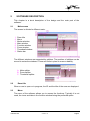
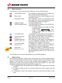
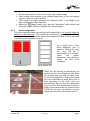
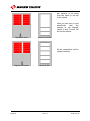
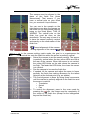
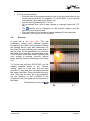

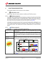
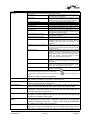
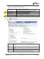
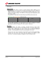
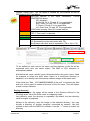
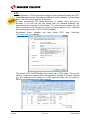
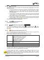
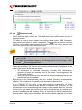
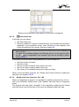
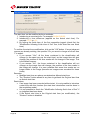
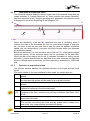
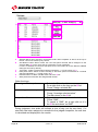


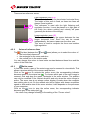
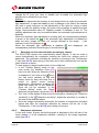
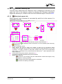
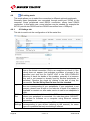
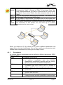
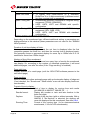

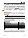
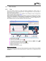
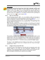
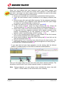

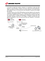

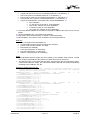
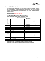
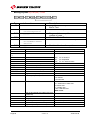
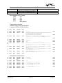
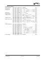
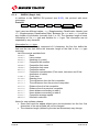


![English [2012v1]](http://vs1.manualzilla.com/store/data/005666127_1-015c2c1b906ab908850f1f1f8721a849-150x150.png)


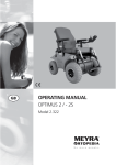


![English [2014v1]](http://vs1.manualzilla.com/store/data/005775879_1-a83e57144a66539570f80a48a6e80397-150x150.png)