1
Installation/User Manual X529/e529
Part Numbers 02-9487-D & 01-9488.xxx
Revision 3.1, Issued 9/12/06
INNCOM international, inc.
Plasma TV is the problem, contact an Inncom application engineer to discuss a solution.
6.4
If this is a centrally controlled system and the required room gateway device (i.e., TCT, TCC or
B485) has been installed and powered, verify that the X529 is communicating with the gateway
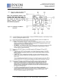
device. A second “dot” will appear in the lower right of the display AND the “DIAG” LED on the
X529 will blink twice per second when the X529 is communicating with the room gateway device.
If the second dot does NOT appear and the DIAG LED continues to blink once every two
seconds, investigate the following possible causes:
6.4.1
If the gateway device is a TCT/TCC, verify:
6.4.1.1 The TCT/TCC power cable is completely plugged into a powered AC outlet and
into the TCT/TCC DC power jack
6.4.1.2 The TCT/TCC Eye5 module is correctly connected to the TCT/TCC H1 header
6.4.1.3 The distance and line of sight between the TCT/TCC Eye5 module and the X529
Eye5 module are acceptable for IR communication between the devices
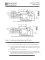
6.4.1.4 If the gateway device is B485, verify that the 5-pin cable is connected between
the B485 H1 header and the X529 H4 header AND that the 2-pin connector tied
to the incoming CINET/FLN5 twisted pair is fully plugged into the B485 H1
header. Also, the GREEN wire from the B485 H3 cable should be connected to
the CINET/FLN5 “A” wire, and the RED wire from the B485 H3 cable should be
connected to the CINET/FLN5 “B” wire.
Note: The IN4 LED on the X529 will be ON if the twisted pair wiring from the B571/B572 Floor
Bridge is connected to the H3 header. However, the second “Dot” on the X529 display will NOT
appear if the twisted pair from the B571/B572 is connected backwards. LOOK FOR THE 2nd DOT
ON THE X529 DISPLAY!
6.5
Verify that the X529 is properly controlling the room HVAC unit using the steps below AFTER
SETTING PROPERTY SPECIFIC PARAMETERS (if required). Be in a position to view the LEDs
on the X529 board and to monitor the operation of the room HVAC unit.
6.6
The following steps check functionality of the e529 and X529 when configured to control an FCU
that has three fan speeds and that is capable of heating and cooling. These steps may require
modification if controlling different equipment, such as a single fan speed Heat Pump with 2nd
stage heat or equipment not capable of heating or cooling.
6.6.1
If the e529 display shows OFF, press the OFF/AUTO button to place the e529 into AUTO
mode.
6.6.2
Lower the “SET” (target) temperature on the e529 to the lowest possible temperature by
using the down arrow button to force the X529 to call for cooling. Verify the X529 OUT4
LED turns ON, indicating the X529 is energizing the COOL signal.
Note: If the OUT4 LED does not turn ON and the HVAC unit does not start cooling, it is possible
that short cycle protection is enabled in the X529, which could prevent cooling for the amount of
time set into Parameter 50. Verify that cooling starts after the short cycle protection time has
elapsed.
16
277 · West Main Street· Niantic, CT · USA · 860-739-4468 · www.inncom.com