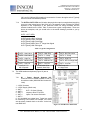
1
INSTALLATION/
USER MANUAL
X529 Logic Board and
e529 Battery Powered Thermostat
277 · West Main Street· Niantic, CT · USA · 860-739-4468 · www.inncom.com
Installation/User
Manual-X529/e529
Revision 3.1
Issued 9/12/06
Installation/User Manual X529/e529
Part Numbers 02-9487-D & 01-9488.xxx
Revision 3.1, Issued 9/12/06
INNCOM international, inc.
Table of Contents
Introduction………………………………………………………………………………………………… 4
Section 1
1.1
1.2
1.3
Installing the e529 Battery Powered Thermostat……………………………………
Installation materials……………………………………………………………………….
Positioning…………………………………………………………………………………..
Mounting…………………………………………………………………………………….
5
5
5
5
Section 2
2.1
2.2
2.3
Installing the X529 Thermostat Controller…………………………………………...
Installation materials……………………………………………………………………….
Positioning…………………………………………………………………………………..
Mounting…………………………………………………………………………………….
6
6
6
7
Section 3 Wiring the FCU/PTAC HVAC Interface and the RB05 or X06……………………… 9
3.1 RB05 Low-Voltage Interface Card……………………………………………………….. 9
3.2 X06 Relay Pack…………………………………………………………………………….. 11
Section 4
4.1
4.2
4.3
Mounting and Connecting the Eye5 IR Module……………………………………... 12
Mounting…………………………………………………………………………………….. 12
Securing……………………………………………………………………………………... 13
Connecting………………………………………………………………………………….. 13
Section 5 Connecting Door and Window Position Inputs to the X529………………………..13
5.1 Using an S541 Door Switch…………………………………………............................... 13
5.2 Using an S241 or Similar…………………………………………................................... 13
Section 6
6.1
6.2
6.3
6.4
6.5
6.6
6.7
6.8
Testing e529/X529 Operation…………………………………………………………… 15
Powering Up……………………………………………………………............................ 15
Verify Diagnostic LED……………………………………………………………………… 15
Verify X529/e529 IR Communication…………………………………………………….. 15
X529 Communicating with Room Gateway……………………………………………… 16
HVAC Control………………………………………………………………………………. 16
3-Fan-Speed FCU Control………………………………………………………………… 16
Door/Window Inputs…………..…………………………………………………………… 17
Set Room ID……….…………..…………………………………………………………… 17
Section 7 X529 Detailed Overview………………………………………………………………….. 18
7.1 X529 LEDs………………………………………………………………………………….. 18
7.2 X529 Headers and Pinouts………………………………………………………………... 19
Section 8 e529 Detailed Overview………………………………………………………………….. 20
8.1 e529 Windows, Control Buttons, and Sensors………………………………………….. 20
8.2 e529 LCD Functions……………………………………………………………………….. 22
2
277 · West Main Street· Niantic, CT · USA · 860-739-4468 · www.inncom.com
Installation/User Manual X529/e529
Part Numbers 02-9487-D & 01-9488.xxx
Revision 3.1, Issued 9/12/06
INNCOM international, inc.
Figures:
Figure 1. X529 Logic Board ............................................................................................................... 4
Figure 2. e529 Battery Thermostat .................................................................................................... 4
Figure 3. Housing and Mounting Plate............................................................................................... 6
Figure 4. Snap-Track ......................................................................................................................... 7
Figure 5. Mod Truss Screws .............................................................................................................. 7
Figure 6. Cards in the Snap Track ..................................................................................................... 7
Figure 7. Installing the X529/X06 Relay Pack Inside the PTAC/FCU Housing ................................. 8
Figure 8. X06 Dimensions.................................................................................................................. 8
Figure 9. Typical Installation .............................................................................................................. 9
Figure 10. RB05 Connected to 3-Fan FCU........................................................................................ 10
Figure 11. RB05 Connected to 2-Fan Heat Pump with 2nd Stage Heat............................................. 10
Figure 12. Wiring Harnesses.............................................................................................................. 11
Figure 13. X529/X06 Connected to 3-Fan Heat/Cool FCU................................................................ 12
Figure 14. X529/X06 Connected to 2-Fan Heat Pump with 2nd Stage Heat...................................... 12
Figure 15. Door Position Input Through RB05 IN1 (RB05 H1 Pin 8 and Pin 1) ................................ 13
Figure 16. Door Position Input through X06 IN1 (X06 H2 Pin 4 and Pin 1)....................................... 14
Figure 17. Connecting Switch Leads to X529 IN2 and IN3 ............................................................... 14
Figure 18. X529 LEDs........................................................................................................................ 18
Figure 19. X529 Headers and Pinouts............................................................................................... 19
Figure 20. e529 Windows, Control Buttons, and Sensors ................................................................. 21
Figure 21. e529 Display and Button Functions .................................................................................. 22
Figure E-1. ES-1 H9 Header .............................................................................................................. 32
Tables:
Table 1. Wiring Color Codes for Typical RB05/X529 Installation ...................................................... 10
Table 2. X06 Relay Functions for Typical Installations ...................................................................... 11
Table 3. Typical Configurations ......................................................................................................... 19
Table 4. Revision History ................................................................................................................... 38
Appendixes:
Appendix A – e529/X529 Service Parameter Mode…………………………………………………….. 24
Appendix B – Setting the Address of the X529 Controller via the e529 Thermostat………………… 26
Appendix C – Changing the P5 Channel of the e529 and X529……………………………………….. 29
Appendix D – Using the Palm Sneezer to Test and Troubleshoot e529/X529 Installations………… 30
Appendix E – Using the ES-1 Flash Memory Module with the e529/X529…………………………… 32
Appendix F – Obtaining Standalone ETM Runtime Data from the X529……………………………… 34
Revision History…………………………………………………………………………………………… 36
3
277 · West Main Street· Niantic, CT · USA · 860-739-4468 · www.inncom.com
Installation/User Manual X529/e529
Part Numbers 02-9487-D & 01-9488.xxx
Revision 3.1, Issued 9/12/06
INNCOM international, inc.
Introduction
The X529 (Figure 1) is an HVAC control board designed to be mounted inside the room FCU/PTAC enclosure.
An infrared (IR) transceiver module connected to the X529 provides wireless communication between the X529
and the e529 battery-operated, wall-mounted thermostat (Figure 2). The X529 board is the “brains” of an
X529/e529 installation and contains the hardware, connection terminals, and logic to control the HVAC unit.
The e529 is the battery-powered “user interface” to the X529 (via its LCD display and buttons) and contains an
internal IR transceiver, a PIR motion sensor, and a temperature and optional humidity sensor. Button presses
and readings from the e529 temperature and optional humidity and occupancy sensors are passed to the
X529 via IR. All logic and decision making with regards to controlling room temperature and humidity (if
desired) is handled by the X529.
The X529 also provides the functionality to communicate and interact with other INNCOM System 5
components installed in the guestroom, such as S541 door/window switch, S217 light switch, and TCT central
interface port. The communication can be wireless, using IR5, or wired via the S5-bus, which is INNCOM’s
System 5 communication bus.
The X529 HVAC outputs available at header H1 are simply active low transistor outputs that cannot drive the
inputs of a typical PTAC/FCU. Therefore, two interface boards are available that connect to the X529 H1
output header and convert the X529 low voltage outputs to the appropriate signals required by the particular
HVAC unit to be controlled:
•
•
RB05 Triac Board (INNCOM Part Number 02-9490.AA). Controlling PTAC/PTHP/FCU units with a
24VAC low-voltage interface. Uses “High-Side” switching.
X06 Line Voltage Relay Board (INNCOM P/N 02-9480). Controlling PTAC/PTHP/FCU units with a
line voltage interface.
Figure 1. X529 Logic Board
Figure 2. e529 Battery Thermostat
4
277 · West Main Street· Niantic, CT · USA · 860-739-4468 · www.inncom.com
Installation/User Manual X529/e529
Part Numbers 02-9487-D & 01-9488.xxx
Revision 3.1, Issued 9/12/06
INNCOM international, inc.
Section 1 Installing the e529 Battery Powered Thermostat
1.1
Required installation materials:
e529 Battery Powered Thermostat:
• Four 6-8 X ¾ plastic conical anchors if mounting to sheetrock wall
• Four 6-32 X ¾ sheet metal screws if attaching to a 4X4 electrical box; provided with e529 kit
• Four AA alkaline batteries; provided with e529 kit
• #0 Phillips screwdriver
1.2
1.3
Position the e529 as follows:
1.2.1
On a partitioning interior wall, and approximately 5 feet (1.5M) above the floor in a
location of average room temperature and with an unobstructed view between the e529
and the X529. Although the IR path between the e529 and X529 does not have to be
direct line-of-sight, objects such as walls, furniture, hanging lamps, and similar
obstructions can impact the IR signal between the e529 and the X529. If possible, mount
the e529 in a location that minimizes these obstructions.
1.2.2
Away from direct sunlight and radiant heat, outside walls and doors, air discharge grills,
and stairwells. Do not mount behind an interior door.
1.2.3
Away from steam or water pipes, warm air stacks, unheated/uncooled areas, and
sources of electrical interference.
1.2.4
Away from fluorescent light fixtures if possible.
Mount the e529 Battery Powered Thermostat as follows:
1.3.1
Separate the e529 body and the mounting plate by pulling the bottom of the mounting
plate away from the e528 body and then pull the mounting plate down.
NOTE: If the back-mounting plate is rotated more than 2 or 3 degrees, the plastic tabs at the top of the
plate may fracture or break off.
1.3.2
Attach the mounting plate to the wall or electrical box with the arrow embossed on the
mounting plate pointing upward.
1.3.3
The e529 is provided with four 6-32 ¾” sheet metal screws for use if mounting the plate
to an existing 4”X4” electrical box. If attaching the mounting plate to a sheetrock or similar
wall surface, install four 6-8 X ¾ anchors. The 4 holes on the mounting plate can be used
to mark the location for the anchors.
1.3.4
Install the 4 AA alkaline batteries provided with the e529 kit into the e529 battery
compartment located on the rear of the e529. NOTE: Use alkaline batteries only.
1.3.5
Depress the battery clamp latch at the top of the battery compartment and then swing
open the battery clamp. Insert the 4 AA alkaline batteries, matching the “+” terminals on
the batteries to the “+” symbols in the battery compartment. Close the battery clamp and
verify the latch is securely fastened.
5
277 · West Main Street· Niantic, CT · USA · 860-739-4468 · www.inncom.com
Installation/User Manual X529/e529
Part Numbers 02-9487-D & 01-9488.xxx
Revision 3.1, Issued 9/12/06
INNCOM international, inc.
1.3.5
Verify that the e529 display is now
showing information. If the display is
blank, verify that the batteries are
completely installed with the right
polarities and that the batteries are not
“dead.”
1.3.6
Hook the tabs at the top rear of the e529
housing into the matching depressions
at the top of mounting plate and rotate
the bottom of the e529 housing toward
the wall until it snaps into the place on
the mounting plate.
1.3.7
Secure the e529 housing to the
mounting plate with the two small
screws provided with the e529. The
screws thread into two small holes on
the bottom of the e529 housing (Figure
3).
Figure 3. Housing and Mounting Plate
Section 2 Installing the X529 Thermostat Controller
2.1
Required installation materials:
X529 with RB05:
• Two ½” long, #8 mod truss lath self-drilling screws
• 12”, 8-pin X529 low voltage harness (INNCOM Part Number 62-1449); provided with X529
• 8 wire nuts or “Dolphin” connectors sized to connect 16 to 22 gauge stranded wiring
• Drill and 1/16” drill bit
X529 with X06 Relay Pack:
• Four #5 self drilling pan-head Phillips screws; ¾” long typical
• Eight ¼” quick-disconnect female spade lug connectors that accept 14-16 gauge wire
• X06 Relay Wiring Harness, INNCOM Part Number 62-1498; provided with X06
• 14-16 gauge wire to connect AC power to X06 and to connect X06 relay outputs to HVAC
equipment
• Drill and 1/16” drill bit
2.2
Position the X529 Thermostat Controller as follows:
2.2.1
The X529 is typically mounted inside the housing of the PTAC/FCU being controlled.
Avoid mounting the X529 near moving or excessively warm parts of the PTAC/FCU.
2.2.2
Connections to the X529 for power, control signals, and the Eye5 module are made using
several headers on the X529 PC board. Make sure sufficient space is available
surrounding the X529 board and the particular interface board (RB05 or X05/X06) so that
these connections can be made.
2.2.3
Diagnostic LED’s are located on the top of the X529 PC board. If possible, mount the
6
277 · West Main Street· Niantic, CT · USA · 860-739-4468 · www.inncom.com
Installation/User Manual X529/e529
Part Numbers 02-9487-D & 01-9488.xxx
Revision 3.1, Issued 9/12/06
INNCOM international, inc.
X529 so that these LED’s can be viewed without great difficulty.
2.3
2.2.4
If installing an X529 with an X06 relay pack, the X06 relay pack requires a 120-277 VAC
50/60Hz power source. Ensure the availability of this source at the installation location.
2.2.5
Verify that any screws or rivets used to mount the X529 snap-track to the PTAC/FCU
housing do not contact the bottom of the X529 or RB05 card.
Mount the X529 Thermostat Controller and RB05 or X06 as follows:
2.3.1
If mounting the X529 card along with an RB05 low-voltage HVAC interface card:
2.3.1.1 The X529 and RB05 card are shipped already installed onto the grey plastic
“snap-track.” Slide both cards off the snap-track.
2.3.1.2 Mount the gray snap-track inside the PTAC/FCU housing or desired location
using two fasteners with a low profile to avoid contacting the bottom of the
X529/RB05 boards when they are installed. Insert the fasteners through the two
slots on the snap-track (Figure 4).
NOTE: ½” long, #8 Mod Truss Lath self-drill screws
(Figure 5) are strongly recommended due to their low
profile, the fact that they do not require a washer or
pre-drilling, and their ease of installation into the
sheet metal of typical FCU/PTAC housings.
Figure 4. Snap-Track
Figure 5. Mod Truss Screws
2.3.1.3 Slide or “snap” the X529 and
RB05 cards into the gray snaptrack. The 8-pin H1 header on the
X529 card should be directly
across from the 8-pin H2 header
on the RB05 card, and the 8-wire
jumper should be connected
between the H1 and H2 headers
(Figure 6).
Figure 6. Cards in the Snap-Track
7
277 · West Main Street· Niantic, CT · USA · 860-739-4468 · www.inncom.com
Installation/User Manual X529/e529
Part Numbers 02-9487-D & 01-9488.xxx
Revision 3.1, Issued 9/12/06
INNCOM international, inc.
2.3.2
If mounting the X529 as part of an X06 power supply/relay pack:
2.3.2.1 The X529 card should already be “snapped” into a tray on top of the X06 relay
pack. Verify that the 8-wire harness is connected between the X529 H1 header
and the X06 H1 header.
2.3.2.2 Mount the X529/X06 Relay Pack inside the PTAC/FCU housing or desired
location with four #5 self drilling pan-head Phillips screws. Insert the screws
through the four mounting holes at each corner of the X06 relay pack and drive
into the FCU/PTAC housing (Figure 7). INNCOM recommends ¾” long screws,
but verify that no wiring will be penetrated on the other side of the housing by the
screw tip.
Figure 7. Installing the X529/X06 Relay Pack Inside the PTAC/FCU Housing
2.3.2.3 The dimensions of the X06 are shown in Figure 8; the X06 with the X529
installed measures 2 inches tall. Verify that there is sufficient space at the
intended mounting location for the X06/ X529 and wiring connections.
Figure 8. X06 Dimensions
8
277 · West Main Street· Niantic, CT · USA · 860-739-4468 · www.inncom.com
Installation/User Manual X529/e529
Part Numbers 02-9487-D & 01-9488.xxx
Revision 3.1, Issued 9/12/06
INNCOM international, inc.
2.3.2.4 If using a screw different from a #5 pan-head Phillips, test fit the screw through
one of the mounting holes to verify the screw will fit cleanly. Do not over-drive the
screw or you may crack the X06 PC board or plastic housing.
Note: Overdriving the screws can crack the X06 housing or PC board.
2.3.2.5 If pre-drilling the four holes, observe the mounting-hole dimensions shown in
Figure 8. The thickness of the X06 at the mounting hole-locations is 5/16”
(0.3125” 7.9 mm).
Section 3 Wiring the FCU/PTAC HVAC Interface and the RB05 or X06
3.1
If using the RB05 low voltage interface card:
3.1.1
Plug the supplied 12-inch, 8-pin harness (INNCOM Part Number 62-1449) onto the H1
header on the RB05 board. The connector is buttoned to fit in only one direction.
3.1.2
Connect the ends of the INNCOM harness wires to the applicable wires of the
PTAC/FCU harness using wire nuts or other approved connectors.
3.1.3
Figure 9 shows a typical installation. Table 1 lists wire colors and functions for the
provided INNCOM 62-1449 harness. Figures 10 and 11 show wiring diagrams for typical
connections to an FCU and PTAC. However, please refer to the property specific wiring
diagram provided by INNCOM for exact connection details.
PTAC/FCU Specific
Inncom 62-1449
RB05 H1 Header
Figure 9. Typical Installation
9
277 · West Main Street· Niantic, CT · USA · 860-739-4468 · www.inncom.com
Installation/User Manual X529/e529
Part Numbers 02-9487-D & 01-9488.xxx
Revision 3.1, Issued 9/12/06
INNCOM international, inc.
Table 1. Wiring Color Codes for Typical RB05/X529 Installation
H1
Harness
Wire
4 Pipe, 3 Fan
Speed, Heat/Cool
FCU
2 Pipe, 3 Fan Speed, Cool
Only FCU
Heat Pump, 2 Fan Speeds,
nd
2 Stage Heat
Heat Pump, 3
Fan Speeds
Brown
24VAC Common
24VAC Common
24VAC Common
Red
Orange
24VAC Hot
Low Fan
24VAC Hot
Low Fan
24VAC Hot
Low Fan
24VAC
Common
24VAC Hot
Low Fan
Yellow
Medium Fan
Medium Fan
W2 -2
Green
High Fan
High Fan
High Fan
High Fan
Blue
Cool Signal
Cool Signal
Y- Compressor
Violet
Heat Signal
N/A
B/O- Reversing Valve
YCompressor
B/OReversing
Valve
nd
Stage Heat
Medium Fan
Figure 10. RB05 Connected to 3-Fan FCU
Figure 11. RB05 Connected to 2-Fan Heat Pump with 2nd Stage Heat
10
277 · West Main Street· Niantic, CT · USA · 860-739-4468 · www.inncom.com
Installation/User Manual X529/e529
Part Numbers 02-9487-D & 01-9488.xxx
Revision 3.1, Issued 9/12/06
INNCOM international, inc.
3.2
If using the X06 Relay Pack:
3.2.1
A harness (INNCOM Part Number 62-1498) (Figure 12) is provided with the X06 to tie AC
Hot to the “COM” terminal of each relay on the X06. Plug each of the connectors on this
harness onto the “COM” terminal on each of the X06’s relays and onto the “Line 1” spade
terminal on the X06.
3.2.2
Connect the free end of this harness to the AC Line supply at the FCU/PTAC with a wire
nut or approved connector.
3.2.3
Connect AC supply Neutral at the FCU/PTAC to the “Line 2” terminal on the X06.
3.2.4
Connect a valid earth to the “EARTH” terminal on the X06.
3.2.5
Connect the X06 relay “NO” (normally open) terminals to the appropriate terminals or
wires in the FCU/PTAC. Use ¼” Quick Disconnect female spade lug connectors that
accept 14-16 gauge wire to connect to each of the X06 “NO” relay terminals.
Figure 12. Wiring Harnesses
Table 2 lists X06 relay functions for typical installations, and Figures 13 and 14 show wiring
diagrams for typical connections to an FCU and heat pump. However, please refer to the
property specific wiring diagram provided by INNCOM for exact connection details.
Table 2. X06 Relay Functions for Typical Installations
4 Pipe, 3 Fan Speed,
Heat/Cool FCU
2 Pipe, 3 Fan Speed,
Cool Only FCU
Heat Pump,
2 Fan Speeds,
2nd Stage Heat
Heat Pump,
3 Fan Speeds
K1
Low Fan
Low Fan
Low Fan
Low Fan
K2
Medium Fan
Medium Fan
W2 -2
K3
High Fan
High Fan
High Fan
K4
Cool Signal
Cool Signal
Y-Compressor
Y-Compressor
K5
Heat Signal
Not Connected
B/O- Reversing Valve
B/O-Reversing
Valve
nd
Stage Heat
Medium Fan
High Fan
11
277 · West Main Street· Niantic, CT · USA · 860-739-4468 · www.inncom.com
Installation/User Manual X529/e529
Part Numbers 02-9487-D & 01-9488.xxx
Revision 3.1, Issued 9/12/06
INNCOM international, inc.
Figure 13. X529/X06 Connected to 3-Fan Heat/Cool FCU
Figure 14. X529/X06 Connected to 2-Fan Heat Pump with 2nd Stage Heat
Section 4 Mounting and Connecting the Eye5 IR Module
4.1
Select the mounting location for the Eye5 module using the following guidelines:
4.1.1
Do not mount behind a door that can completely cover the Eye5 module when opened.
4.1.2
Do not mount underneath or behind grating or louvers in the PTAC/FCU housing such
that they are directly in front of the Eye5 module. Avoid objects directly in front of the
Eye5 module.
4.1.3
Avoid mounting near fluorescent lighting fixtures.
4.1.4
Avoid mounting the Eye5 module inside the FCU/PTAC housing if it is apparent that the
Eye5 module will NOT have an unobstructed view out into the room and toward any other
INNCOM IR devices; specifically, the e529 battery powered thermostat.
12
277 · West Main Street· Niantic, CT · USA · 860-739-4468 · www.inncom.com
Installation/User Manual X529/e529
Part Numbers 02-9487-D & 01-9488.xxx
Revision 3.1, Issued 9/12/06
INNCOM international, inc.
4.1.5
The Eye5 module comes with either a 4”, 12” or 20” wiring harness with a 5-pin connector
attached that plugs onto the H3 header on the X529 card. Choose a mounting location for
the Eye5 module that is within the length of one of these available wiring harnesses.
Note: If you have access to a Palm IR5 Tool, the “Device Configuration” program can be used to
monitor the IR5 “gain” level at the e529 mounting location and different locations in the room. Use
this tool to determine if the desired mounting location of the X529 Eye5 module will allow
adequate communication between the X529 and the e529 or other IR5 devices.
4.2
Secure the Eye5 module using the two screws provided with the module, double-sided tape, or
zip-ties. How the Eye5 module is secured will depend on the particular mounting location.
4.3
Connect the Eye5 module wiring harness to the X529 H3 5-pin header. The H3 header is keyed
so that the connector will fit in only one direction.
Section 5 Connecting Door and/or Window Position Inputs to the X529
Note: This section applies only if you are monitoring room door or window positions.
5.1
If using an INNCOM S541 IR door switch: An INNCOM S541 IR battery-powered door position
switch is typically used to report room entry door position to the X529. Since the S541 sends door
position to the X529 via IR, no low voltage wiring is required between the S541 and the X529.
Refer to the S541 Installation Guide document for installation instructions.
5.2
If connecting an INNCOM S241 door switch or similar low-voltage door/window position switch:
The X529 can monitor up to three low voltage inputs (IN1, IN2 or IN3) in order to read door or
window positions. If monitoring a single door, such as the room entry door, the IN1 low-voltage
input on the X529 is typically used.
5.2.1
If using an RB05: IN1 is the GRAY wire on the 8-pin harness that plugs onto the RB05
H1 header. Connect the switch wires to the GRAY (Pin 8) and BROWN (Pin 1) wires of
the RB05 H1 harness (Figure 15).
Figure 15. Door Position Input through RB05 IN1 (RB05 H1 Pin 8 and Pin 1)
13
277 · West Main Street· Niantic, CT · USA · 860-739-4468 · www.inncom.com
Installation/User Manual X529/e529
Part Numbers 02-9487-D & 01-9488.xxx
Revision 3.1, Issued 9/12/06
INNCOM international, inc.
5.2.2
If using an X06: IN1 is the YELLOW wire on the 4-pin harness that plugs onto the X06 H2
header. Connect the switch wires to the YELLOW (Pin 4) and BROWN (Pin 1) wires of
the X06 H2 4-pin harness (Figure 16).
Figure 16. Door Position Input through X06 IN1 (X06 H2 Pin 4 and Pin 1)
5.2.3
If using IN2 or IN3 on the X529 H2 header: IN2 is the RED wire and IN3 is the ORANGE
wire on the 3-pin harness that plugs onto the X529 H2 header.
5.2.3.1 If using IN2, connect switch wires to the RED (IN2) and BROWN (Pin 1) wires of
the H2 3 pin harness (Figure 17).
5.2.3.2 If using IN3, connect switch wires to the ORANGE (IN2) and BROWN (Pin 1)
wires of the H2 3-pin harness (Figure 17).
X529
Figure 17. Connecting Switch Leads to X529 IN2 and IN3
14
277 · West Main Street· Niantic, CT · USA · 860-739-4468 · www.inncom.com
Installation/User Manual X529/e529
Part Numbers 02-9487-D & 01-9488.xxx
Revision 3.1, Issued 9/12/06
INNCOM international, inc.
Section 6 Testing e529/X529 Operation
6.1
Apply power to the HVAC unit, the X529, and any other INNCOM devices in the room, such as
the X06 or TCT.
6.2
Verify that the “DIAG” LED on the X529 begins to flash. This indicates that the X529 has power
and that it is executing its software. If the DIAG LED is not flashing:
6.3
6.2.1
Verify that the 8-wire jumper is connected between the X529 H1 header and the RB05
H2 header, or the X529 H1 header and the X06 H1 header.
6.2.2
Verify that the breaker controlling power to the HVAC unit or the transformer supplying
the X529 is shut.
Verify that the X529 and e529 are communicating via IR. A “dot” will appear in the lower right
corner of the e529 display when the e529 and the X529 are communicating. If no dot is present,
press the “OFF/AUTO” button on the e529 a few times to force it to send a message to the X529.
The dot should appear in the lower left corner of the e529 display within a few seconds.
Note: If two dots appear on the e529 display, that is okay. The 2nd dot indicates the X529 is
part of a centralized system and is communicating with the particular gateway device
(TCT, TCC, B485, etc). In standalone properties with no Central Interface computer, only
one dot will appear on the e529 display.
If a dot does not appear on the e529 display, even after pressing the OFF/AUTO button several
times, the e529 is not able to communicate with the X529. Check the following:
6.3.1
Verify that the Eye5 module is correctly plugged onto the X529 H3 header.
6.3.2
Verify that the path between the X529 and the e529 is not blocked by a large obstruction,
or that the distance between the e529 and the Eye5 module is not too great. If necessary,
reposition the Eye5 module to achieve a better line of sight or smaller distance between
the X529 and the e529.
6.3.3
If another IR5 capable device is in the room, such as a TCT or an X05, and it is between
the X529 and the e529, try enabling the IR5 repeater function in that device. This may
improve IR communication between the e529 and the X529. “Repeater” configuration is
an advanced feature of INNCOM IR devices and is beyond the scope of this manual.
Contact an INNCOM application engineer for guidance.
6.3.4
Verify that the low battery symbol is not being displayed in the upper
left corner of the e529 display. If it is, replace the 4 AA batteries in the
e529, and then verify that the “dot” appears.
6.3.5
Verify that the e529 and the X529 are assigned the same IR5 “Channel. Contact an
INNCOM application engineer if not familiar with checking or setting IR5 channels.
6.3.6
Does the room have a plasma television installed? These have been known to cause
interference with IR5 communications. Turn OFF the plasma TV and see if IR5
communication between the e529 and X529 improves and the “dot” appears. If the
15
277 · West Main Street· Niantic, CT · USA · 860-739-4468 · www.inncom.com
Installation/User Manual X529/e529
Part Numbers 02-9487-D & 01-9488.xxx
Revision 3.1, Issued 9/12/06
INNCOM international, inc.
Plasma TV is the problem, contact an Inncom application engineer to discuss a solution.
6.4
If this is a centrally controlled system and the required room gateway device (i.e., TCT, TCC or
B485) has been installed and powered, verify that the X529 is communicating with the gateway
device. A second “dot” will appear in the lower right of the display AND the “DIAG” LED on the
X529 will blink twice per second when the X529 is communicating with the room gateway device.
If the second dot does NOT appear and the DIAG LED continues to blink once every two
seconds, investigate the following possible causes:
6.4.1
If the gateway device is a TCT/TCC, verify:
6.4.1.1 The TCT/TCC power cable is completely plugged into a powered AC outlet and
into the TCT/TCC DC power jack
6.4.1.2 The TCT/TCC Eye5 module is correctly connected to the TCT/TCC H1 header
6.4.1.3 The distance and line of sight between the TCT/TCC Eye5 module and the X529
Eye5 module are acceptable for IR communication between the devices
6.4.1.4 If the gateway device is B485, verify that the 5-pin cable is connected between
the B485 H1 header and the X529 H4 header AND that the 2-pin connector tied
to the incoming CINET/FLN5 twisted pair is fully plugged into the B485 H1
header. Also, the GREEN wire from the B485 H3 cable should be connected to
the CINET/FLN5 “A” wire, and the RED wire from the B485 H3 cable should be
connected to the CINET/FLN5 “B” wire.
Note: The IN4 LED on the X529 will be ON if the twisted pair wiring from the B571/B572 Floor
Bridge is connected to the H3 header. However, the second “Dot” on the X529 display will NOT
appear if the twisted pair from the B571/B572 is connected backwards. LOOK FOR THE 2nd DOT
ON THE X529 DISPLAY!
6.5
Verify that the X529 is properly controlling the room HVAC unit using the steps below AFTER
SETTING PROPERTY SPECIFIC PARAMETERS (if required). Be in a position to view the LEDs
on the X529 board and to monitor the operation of the room HVAC unit.
6.6
The following steps check functionality of the e529 and X529 when configured to control an FCU
that has three fan speeds and that is capable of heating and cooling. These steps may require
modification if controlling different equipment, such as a single fan speed Heat Pump with 2nd
stage heat or equipment not capable of heating or cooling.
6.6.1
If the e529 display shows OFF, press the OFF/AUTO button to place the e529 into AUTO
mode.
6.6.2
Lower the “SET” (target) temperature on the e529 to the lowest possible temperature by
using the down arrow button to force the X529 to call for cooling. Verify the X529 OUT4
LED turns ON, indicating the X529 is energizing the COOL signal.
Note: If the OUT4 LED does not turn ON and the HVAC unit does not start cooling, it is possible
that short cycle protection is enabled in the X529, which could prevent cooling for the amount of
time set into Parameter 50. Verify that cooling starts after the short cycle protection time has
elapsed.
16
277 · West Main Street· Niantic, CT · USA · 860-739-4468 · www.inncom.com
Installation/User Manual X529/e529
Part Numbers 02-9487-D & 01-9488.xxx
Revision 3.1, Issued 9/12/06
INNCOM international, inc.
6.6.3
Press the FAN button on the e529 to force the X529 into FIXED FAN mode. Each time
you press the FAN button, the X529 will cycle through LO, MED, and HIGH fan speeds.
Verify the X529 OUT1 (LO Fan), the OUT2 (MED Fan) and the OUT3 (HIGH Fan) LEDs
turn ON and the fan in the HVAC unit cycles between LO, MED, and HIGH speeds as
you press the FAN button several times. Also, verify that the unit is COOLING.
6.6.4
Raise the “SET” (target) temperature on the e529 to the maximum temperature using the
up button to force the X529 to call for heating. Verify the OUT5 LED turns ON indicating
the X529 is energizing the HEAT signal.
6.6.5
Press the FAN button on the e529 to force the X529 into FIXED FAN mode. Each time
you press the FAN button, the X529 will cycle through LO, MED, and HIGH fan speeds.
Verify that the X529 OUT1 (LO Fan), the OUT2 (MED Fan), and the OUT3 (HIGH Fan)
LEDs turn ON and the fan in the HVAC unit cycles between LO, MED, and HIGH speeds
as you press the FAN button several times. Also, verify that the unit is HEATING.
6.6.6
If any of the above tests indicate a problem, check the following common symptoms:
6.6.6.1 Verify the Eye5 IR module is completely plugged onto the X529 H1 header and
that there is a good line-of-sight between the Eye5 and the e529 battery
thermostat.
6.6.6.2 Verify that the 8-pin jumper is completely connected between the X529 H1
header and the RB05 H2 header for 24VAC applications or between the X529 H1
header and the X06 H1 header for line voltage applications.
6.6.6.3 Verify the wiring connections between the RB05 card and the particular low
voltage control inputs on the HVAC unit for low voltage systems and the wiring
between the relay terminals on the X06 relay pack and the line voltage
connections on the HVAC unit for line voltage systems.
6.6.6.4 Verify that the e529 batteries are not discharged. Check for the low battery
symbol on the e529 display.
6.6.6.5 Check to see if the room has a plasma television. These are known to cause
interference with IR5 signals. Turn OFF the plasma television and retry.
6.7
Check operation of any low voltage door or window inputs to the X529.
6.7.1
6.8
If using a wireless S541 IR door position sensor, NO INDICATION OR TEST IS
AVAILABLE DIRECTLY FROM THE e529 or X529 to test that the S541 is correctly
sending door position to the X529 and that the X529 detected the message. However, if
the e529/X529 is part of a centrally-controlled system and the CIS server and appropriate
communication network has been established, the CIT5 “Room View > AC Tab” can be
used to monitor reported door position. Open the door and leave it open, and then go to
the appropriate room in CIT5 and check that the appropriate door status indicates OPEN.
It can take several minutes before the door status appears. CLOSE the door and verify
the door status indicates CLOSED.
If the “Room ID” is known, set it in the X529 by following the procedure in Appendix B.
17
277 · West Main Street· Niantic, CT · USA · 860-739-4468 · www.inncom.com
Installation/User Manual X529/e529
Part Numbers 02-9487-D & 01-9488.xxx
Revision 3.1, Issued 9/12/06
INNCOM international, inc.
Note: A utility is available on the Palm PDA “Sneezer” to monitor the IR5 message that is sent
from the S541 and the subsequent acknowledgement from the X529. If you have a Sneezer, use
the “Door Status” program to test the S541 and its ability to send door position to the X529.
Contact an INNCOM application engineer for details.
6.8.1
If connecting a door or window switch to one of the X529 low voltage inputs (IN1, IN2 or
IN3), you can use the IN1, IN2 or IN3 LEDs on the X529 to verify door switch operation
and ensure that the wiring between the switch and the X529 is correct. The wiring
diagram supplied to the property will indicate which of the three inputs is being used for
the particular door/window input and how to connect it to the X529.
6.8.2
For typical installations NOT using an S541 IR door switch, IN1 on the X529 is used to
monitor the room entry door; therefore, the IN1 LED will be ON when the door is SHUT.
In that case:
6.8.3
If an RB05 is being used with an X529, the door switch leads should be connected to the
GRAY wire (Pin 8) and the BROWN wire (Pin 1) on the RB05 H1 harness.
6.8.4
If an X529 is being used with an X06 relay pack, the door switch leads should be
connected to the YELLOW (Pin 4) and the BROWN (Pin 1) on the 4-pin harness that
plugs onto the 4-pin H2 header on the X06 board.
Section 7 X529 Detailed Overview
7.1
Ten LEDs (DIAG, IN4-IN1, and OUT5-OUT1)
(Figure 18) on the X529 provide the following
information:
7.1.1
The DIAG LED blinks when 12VDC power
is supplied to the X529. For centralized
systems with a Central Interface computer
(CIS), it blinks two times/second when the
X529 is communicating with the room
gateway device (TCT, TCC or B485). If
the property is standalone (no CIS central
interface) or the X529 is NOT
communicating with the room gateway
device due to a problem, it blinks once
every two seconds.
7.1.2
The IN4 LED is ON when the X529 is
connected to an active twisted pair
communication network (FLN5/CINET)
from a B572 or B571 Floor Bridge via a
B485 module. Note: This LED will be ON
even if the twisted pair wiring (CINET A
and CINET B) is connected backward.
7.1.3
Figure 18. X529 LEDs
The IN3, IN2, and IN1 LED’s are ON when the associated low voltage input on the H1
18
277 · West Main Street· Niantic, CT · USA · 860-739-4468 · www.inncom.com
Installation/User Manual X529/e529
Part Numbers 02-9487-D & 01-9488.xxx
Revision 3.1, Issued 9/12/06
INNCOM international, inc.
(IN1) and H2 (IN2 and IN3) headers is connected to Common through a switch. Typically
used to monitor door/window positions.
7.1.4
The OUT5 to OUT1 LEDs are ON when that particular output is energized and supplying
current to a low voltage input of the HVAC unit. The purpose of each of these five outputs
depends on the requirement of the particular HVAC unit being controlled and the
software loaded into the X529. Table 3 shows three typical configurations. These are
shown as examples, and you should refer to the actual drawings provided to you by
INNCOM.
OUT5 – OUT1 LEDs
OUT5 Typically HEAT call signal
OUT4 Typically COOL call signal
OUT3 Typically HIGH FAN signal
OUT2 Typically MED FAN or 2nd Stage Heat Signal
OUT1 Typically LOW FAN signal
Table 3. Typical Configurations
OUT5 - Heat Valve
OUT5 - Heat Strip
OUT5 - B/O Rev Valve
OUT4 - Cool Valve
OUT4 - Y- Comp
OUT4 - Y- Comp
OUT3 - High Fan
OUT3 - High Fan
OUT3 - High Fan
OUT2 - Medium Fan
OUT2 - Medium Fan
OUT2 - W2 2 nd Stage Heat
OUT1 - Low Fan
OUT1 - Low Fan
OUT1 - Low Fan
Heat/Cool FCU
with 3 Speeds
7.2
PTAC with 3 Fan
Speeds, Heat Strip
Heat Pump with
2nd stage Heat
The X529 headers and pinouts (Figure 19) are as
follows:
7.2.1
H1 – Power, Ground, Outputs, IN1.
Connects to the H2 header of RB05 or X06 via
8-conductor cable (INNCOM Part Number 621484).
1 - 12VDC Common
2 - 12VDC Supply (50mA max)
3 - OUT 1
OUT 1-5: Open Collector
4 - OUT 2
outputs to drive PTAC/FCU
5 - OUT 3
inputs. Can source 5mA each.
6 - OUT 4
7 - OUT 5
8 - IN1 Available low voltage input. Typical use could
be monitoring a door switch, for example, if the X529
was physically located close to the door. Active low,
max draw 5mA.
Figure 19. X529 Headers and Pinouts
19
277 · West Main Street· Niantic, CT · USA · 860-739-4468 · www.inncom.com
Installation/User Manual X529/e529
Part Numbers 02-9487-D & 01-9488.xxx
Revision 3.1, Issued 9/12/06
INNCOM international, inc.
7.2.2
H2 – Low Voltage Inputs IN2 and IN3
1 – Common
2 – IN2 Available low voltage input. Typical use could be monitoring a door switch; for
example, if the X529 were physically located close to the door. Active low, 5mA.
3 – IN3 Available low voltage input. Typical use could be monitoring a door switch; for
example, if the X529 were physically located close to the door. Active low, 5mA.
7.2.3
H3 – Eye5 Module Connector. Plug Eye5 IR5 module into this header so the X529 can
communicate with the e529 and other room devices via IR5 infrared signal.
7.2.4
H4 – S5 Bus / FLN5 Communication Header. Provides the ability to connect the 3 wire
S5-Bus to communicate with S5-Bus capable room devices and/or the RS485 twisted
pair CINET bus (via B485 module) wiring to the X529.
1 – Common
2 – S5 Bus +12VDC
3 – S5 Bus TX/RX Data
4 – Tx Data (CINET A) when connected to B485 module
5 – Rx Data (CINET B) when connected to B485 module
7.2.5
H5 – Thermistor A , Input, H6 – Thermistor B Input. Provide the ability to connect 10K
external thermistor temperature sensors to the X529. A total of two of these temperature
sensors can be connected to provide FCU pipe water temperature or measured room
temperature.
7.2.6
H7 – ICP Programming Header. Connect programming cable from In-Circuit-Programmer
(ICP) to upload new software to the X529.
7.2.7
H8 – Expansion Header Future Growth. Not currently used.
7.2.8
H9 – ES1 Header. Connect ES1 Flash Programmer Module to this header to copy
software from the X529 to the ES1 or to upload new software from the ES1 to the X529.
Section 8 e529 Detailed Overview
8.1
Figure 20 shows the windows, control buttons, and sensors of the e529; they are:
8.1.1
Infrared (IR) Communication Window – Allows the e529 to communicate with the X529
room controller wirelessly using IR signals.
8.1.2
LCD Display and Control Buttons – The e529 is the battery powered “user interface” for
the X529 room controller. Information provided on the LCD display and control buttons
provide the ability for the guest to monitor and control room temperature using the e529.
8.1.3
Temperature and Humidity Sensors – Measure room temperature and humidity
(optional); the measurements are sent to the X529 via IR signal.
8.1.4
Passive Infrared Motion Sensor (PIR) – Occupancy sensor installed in the e529. Detects
guest motion, which is then reported to the X529 via IR signal.
20
277 · West Main Street· Niantic, CT · USA · 860-739-4468 · www.inncom.com
Installation/User Manual X529/e529
Part Numbers 02-9487-D & 01-9488.xxx
Revision 3.1, Issued 9/12/06
INNCOM international, inc.
8.1.5
In Circuit Programmer Header – Provides the ability to upload new software to the e529
to upgrade features.
Figure 20. e529 Windows, Control Buttons, and Sensors
21
277 · West Main Street· Niantic, CT · USA · 860-739-4468 · www.inncom.com
Installation/User Manual X529/e529
Part Numbers 02-9487-D & 01-9488.xxx
Revision 3.1, Issued 9/12/06
INNCOM international, inc.
8.2
Figure 21 shows the e529 LCD
display and button functions.
Note: The information shown in the
example e529 display below does not
represent the actual e529 display in
use. Figure 22 shows all possible
display elements turned on for
demonstration purposes.
Figure 21. e529 Display and Button
Functions
22
277 · West Main Street· Niantic, CT · USA · 860-739-4468 · www.inncom.com
Installation/User Manual X529/e529
Part Numbers 02-9487-D & 01-9488.xxx
Revision 3.1, Issued 9/12/06
INNCOM international, inc.
23
277 · West Main Street· Niantic, CT · USA · 860-739-4468 · www.inncom.com
Installation/User Manual X529/e529
Part Numbers 02-9487-D & 01-9488.xxx
Revision 3.1, Issued 9/12/06
INNCOM international, inc.
Appendix A – e529/X529 Service Parameter Mode
Accessing the X529 service parameters is done using the e529. The X529 does not have its own display
and buttons to view or change service parameter values. Instead, the buttons and display on the e529 are
used to view and change the X529 service parameters. When you enter parameter mode on the e529,
messages are actually sent from the e529 to the X529 to access the parameter values stored in the
X529.
The e529 does have a very limited set of parameters, called “local” e529 parameters, which can be
viewed and changed from the e529. Entering local parameter mode on the e529 to view or change these
local parameters is discussed below.
Entering X529 Service Mode
Execute the following sequence on the e529 battery thermostat:
1. Press (and keep pressed) the F/C button on the e529.
2. Press and release the OFF/AUTO button on the e529.
3. Press and release the DISPLAY button on the e529.
4. Release the F/C button.
5. The LCD will display P 0 (Parameter 0) in the middle of the display.
6. Quickly press the UP or DOWN button on the e529 to select the desired parameter number. If you
wait more than five seconds after entering service mode without pressing a button, the e529 will
revert to normal operation.
7. Press the DISPLAY button on the e529 to show the value of the selected parameter. The e529
actually sends a command via IR to the X529 to retrieve the value of the selected parameter.
Note: If the e529 is not able to communicate with the X529 and does not get a reply from the
X529, “- - -” will appear on the e529 display. If this occurs, refer to the troubleshooting section.
8. To change a particular X529 parameter value once displayed, use the UP or DOWN arrow buttons to
change the displayed value of the selected parameter, then press the DISPLAY button to send the
new parameter value to the X529. You must press the DISPLAY button make the change take place.
9. To exit parameter mode, press the F/C button.
Entering “Local” Parameter Mode on the e529
The e529 does have a few local parameters that can be viewed and changed. To view and edit these
local e529 parameters, you must enter the local parameter mode on the e529. Use the following steps to
enter e529 local parameter mode and to change a local parameter value:
1.
2.
3.
4.
5.
Press (and keep pressed) the F/C button on the e529.
Press and release the Off/Auto button on the e529.
Press and release the Display button on the e529.
Release the F/C button.
The LCD will display P 0 (Parameter 0) in the middle of the display.
6. Quickly press the UP button on the e529 until P 2 (Parameter 2) is displayed. If you wait
more than five seconds after entering service mode without pressing a button, the e529 will
revert to normal operation.
24
277 · West Main Street· Niantic, CT · USA · 860-739-4468 · www.inncom.com
Installation/User Manual X529/e529
Part Numbers 02-9487-D & 01-9488.xxx
Revision 3.1, Issued 9/12/06
INNCOM international, inc.
7. Press the DISPLAY button on the e529 to show the value of Parameter 2. Press the UP button to
increase the displayed value to “6”, then press the DISPLAY button to enter e529 local parameter
mode.
“LO MED HI” will appear at the bottom of the e529 display to indicate local parameter mode has been
entered.
8. To change a particular e529 local parameter value, use the UP or DOWN arrow buttons to change
the displayed value of the selected parameter, then press the OFF/AUTO button to store the new
value.
After pressing the OFF/AUTO button to store the new local parameter value, the e529 will reset.
9. If there is another e529 local parameter that you need to change, you must re-enter local parameter
mode by going back to step 1.
e529 Local Parameters:
PAR 0
PAR 1
PAR 2
PAR 3
PAR 4
PAR 5
EEPROM Tag: Value 187
Temperature Offset: 100=0°F; 200=+10°F; 0=-10°F.
Humidity Offset: 100=0%rh, 200=+10%rh; 0=-10%rh
PIR Sensitivity: [1..10] 1=ultra sensitive; 3=default; 6=weak
Humidity Option: 0=disabled, 1=enabled
Operating Modes:
Bit 0: When set, operate the Display button as Heat/Cool mode.
Bit 1: Undefined
Bit 2: Undefined
Bit 3: Undefined
Bit 4: Undefined
Bit 5: Undefined
Bit 6: Undefined
Bit 7: Undefined
25
277 · West Main Street· Niantic, CT · USA · 860-739-4468 · www.inncom.com
Installation/User Manual X529/e529
Part Numbers 02-9487-D & 01-9488.xxx
Revision 3.1, Issued 9/12/06
INNCOM international, inc.
Appendix B – Setting the Address of the X529 Controller via the e529
Thermostat
Follow Procedures 1, 2, and 3 to set the address of the X529 controller.
Procedure 1 Place the e529 into service mode.
STEP A
Press and hold the “F/C” button. This button is
recessed slightly, so try to use the tip of your finger
to ensure the button is fully pressed.
STEP B
While still pressing the “F/C”
button, press and release the
“OFF/AUTO” button.
STEP C
While still pressing the “F/C”
button, press and release the
“DISPLAY” button.
“PAR” and “0” will appear in the display, indicating you have entered
the “Parameter Select” mode of the e529/X529 service mode with
parameter “0” selected. Continue with step 2 to set the X529 address.
26
277 · West Main Street· Niantic, CT · USA · 860-739-4468 · www.inncom.com
Installation/User Manual X529/e529
Part Numbers 02-9487-D & 01-9488.xxx
Revision 3.1, Issued 9/12/06
INNCOM international, inc.
Note: In the example address being entered in steps (a) to (l) below, Parameters 10,11, and 12 are
being entered for “Room 321” which has Par 10=0, Par 11=3, and Par 12=21.
27
277 · West Main Street· Niantic, CT · USA · 860-739-4468 · www.inncom.com
Installation/User Manual X529/e529
Part Numbers 02-9487-D & 01-9488.xxx
Revision 3.1, Issued 9/12/06
INNCOM international, inc.
Procedure 3. Reset the X529 from the e529.
The X529 must be reset to take its new address. Execute Parameter 1, value 14 to reset the X529 using Steps A
through D below.
A. Toggle back to Parameter mode by pressing OFF.
B. Use the up or down arrows to change the displayed
parameter to “1” (Reset ).
C. Press the OFF/AUTO key to select VAL to show
the value 0. Increase the value to 14.
Value “14” shown
D. Press DISPLAY to reset the X529. A reset will begin, causing the HVAC to cycle.
There is no indication on the e529.
28
277 · West Main Street· Niantic, CT · USA · 860-739-4468 · www.inncom.com
Installation/User Manual X529/e529
Part Numbers 02-9487-D & 01-9488.xxx
Revision 3.1, Issued 9/12/06
INNCOM international, inc.
Appendix C – Changing the P5 Channel of the e529 and
X529
The default channel assigned to the e529 and X529 is Channel 1. If you need to change the channel, you
MUST FIRST change the channel for the X529, then enter local parameter mode and change the channel
for the e529. If you change the e529 channel first, you will not be able to subsequently communicate with
the X529 to change its channel.
Note: You CANNOT change the channel in the e529 using a Palm Sneezer. You CAN change the
channel in the X529 using the Palm Sneezer.
1. Enter X529 Service Parameter Mode and change the X529 channel stored in X529 Par 224:
A
Press (and keep pressed) the F/C button on the e529.
B
Press and release the OFF/AUTO button on the e529.
C
Press and release the DISPLAY button on the e529.
D
Release the F/C button.
E The LCD will display P 0 (Parameter 0) in the middle of the display. Quickly press the DOWN
button on the e529 until P 224 (Parameter 224) appears.
F Press the OFF/AUTO button to show the value of parameter 224. “V” (value) and a 2-digit hex
number (XX.h) will appear. The left number is the current channel of the X529. Use the UP or
DOWN arrow buttons to raise/lower the value until the left digit is the desired channel, AND the
right digit is the same as it was before.
G
Press the OFF/AUTO button to save the new X529 channel. The e529 will reset.
2. Enter local Parameter Mode on the e529 and change the channel stored in e529 Local Par 224
A
Press (and keep pressed) the F/C button on the e529.
B
Press and release the Off/Auto button on the e529.
C
Press and release the Display button on the e529.
D
Release the F/C button.
E
The LCD will display P 0 in the center of the display.
Quickly press the UP arrow button until P 2 is selected. If you wait more than five seconds after
entering service mode without pressing a button, the e529 will revert to normal operation.
F Press the DISPLAY button on the e529 to show the value of Parameter 2. Press the UP button to
increase the displayed value to 6 then press the DISPLAY button to enter e529 local parameter
mode.
““LO MED HI” will appear at the bottom of the e529 display and P 0 will appear in the center to
indicate local service mode is active with local parameter 0 selected.
G
Once in local parameter mode, use the DOWN arrow button to change the displayed local
parameter number to 224.
H. Press the DISPLAY button on the e529 to show the value of Parameter 224. The displayed value
will be a 2-digit hex number, with the left digit representing the channel #. Use the UP/DOWN
arrow buttons to raise/lower the value until the left digit is the desired channel, AND the right digit
is the same as it was before.
I
Save the change by pressing the OFF/AUTO button. The e529 will reset.
29
277 · West Main Street· Niantic, CT · USA · 860-739-4468 · www.inncom.com
Installation/User Manual X529/e529
Part Numbers 02-9487-D & 01-9488.xxx
Revision 3.1, Issued 9/12/06
INNCOM international, inc.
Appendix D – Using the Palm Sneezer to Test and Troubleshoot
e529/X529 Installations
Testing S541 IR Door Position Reporting
The e529 does not have a door test service function like the e528. However, the Palm PDA sneezer has
an available program called “Door Test Utility” that can be used to completely test S541 door position
reporting to the X529. Refer to the document Palm Door Switch Tester Utility.PDF for complete
instructions.
If using an S541 IR door switch for door position reporting:
1.
2.
3.
4.
Start the Door Switch Tester program if not already started.
Verify all 3 filters (Door Srv, Swtch Add and Ch) are set to “0”.
Tap the Start button. Running will flash at the bottom of the display.
Open the door and verify the following sequence of events:
• 209 should appear as the switch address.
• Jst Open should appear initially as the switch status.
• Open should appear as the door position server status.
• Open should than appear as the door switch status.
5.
Shut the door and verify the following sequence of events:
• 209 should appear as the switch address.
• Jst Shut should appear initially as the switch status.
• Shut should appear as the door position server status.
• Shut should than appear as the door switch status.
S541 troubleshooting:
1. If the switch address field remains blank, the Palm tester did not see any door position message
traffic. Try opening and shutting the door again. If you still do not get any switch address or switch
status or it’s intermittent, verify that you are not too far away from the S541, and check to see if
you have a bad line-of-site with the S541. Also verify that the batteries in the S541 are OK. The
last number of the reported switch message indicates the battery state in the S541. If the last
number is 0, the batteries are good. If the last number is 1, the batteries are low and should be
changed.
Example of Switch Msg with good batteries: [.500D10060040]
Example of Switch Msg with low batteries: [.500D10060041]
Note: Version 3.0 of the Door Test program will pop up a window indicating Low Battery if
the S541 is reporting its battery is low.
2. If the door server status remains blank for a few seconds and then changes to No Srv!
accompanied by an audible beep, the X529 did not see the door position message from the
S541. It is vital for the room door server (which is the X529) to receive door open/shut status from
the S541 or other door switches in the room. Several other room status servers such as
occupancy and HVAC control use the current entry door status reported by this door server
message to function correctly.
If No Srv! appears for door server status, verify that the installation and position of the X529.
30
277 · West Main Street· Niantic, CT · USA · 860-739-4468 · www.inncom.com
Installation/User Manual X529/e529
Part Numbers 02-9487-D & 01-9488.xxx
Revision 3.1, Issued 9/12/06
INNCOM international, inc.
Does it have power? Is its IR5 Eye connected properly? Is it located such that there is a poor IR5
transmission path between the S541 and the X529?
Also check the jumper on the S541. It should be in the left position for room entry door.
Validating IR5 communication between the X529 and other IR5 devices (other than the e529):
There is currently no test to read the AGC level between the e529 and the X529 if you suspect an IR
communication problem between them. You must rely on the e529 to X529 communication “dot” that
appears on the e529 display for this. However, the X529 Device Ping program on the Palm Sneezer can
be used to test communication between the X529 and other IR5 devices in the room, such as a TCT or
S217.
Start the X529 Device Ping program if not already started.
Enter the X529 address in the Addr? field. It should typically be 14.
Enter the P5 channel being used for the devices in the Chanl? field.
Enter the address of the device you want the X529 to “ping” in the Tgt? field.
Tap the Start button to start the test.
The X529 will begin sending commands out to read the target devices type, major and minor
software version, and its AGC level.
7. The raw messages being sent from the X529 (frame sent) and replied from the target device
(frame rcvd) are displayed.
1.
2.
3.
4.
5.
6.
The target device type, major and minor software versions, and the AGC level will be displayed.
The number of times a read message was sent from the X529 to the target device, the number of
responses received, and the success percentage are also displayed.
Indications of poor IR5 communication between the X529 and the target device are a high AGC
level from the target device (typically >40 or so), low percentage success value, and a high Miss
Resp number.
8. To stop the test, tap the Stop button. This will send a reset command to the X529. This is the
only way to stop the test.
31
277 · West Main Street· Niantic, CT · USA · 860-739-4468 · www.inncom.com
Installation/User Manual X529/e529
Part Numbers 02-9487-D & 01-9488.xxx
Revision 3.1, Issued 9/12/06
INNCOM international, inc.
Appendix E – Using the ES-1 Flash Memory Module with the e529/X529
The latest X529 hardware with 64K memory and X529 software
2.102 or later supports the ES-1 flash memory module. This
version adds a tan, 5-pin ES-1 header (H9) to the X529 located
next to the large black 10-pin programming header. Figure E-1
indicates the ES-1 H9 header with a red circle.
The ES-1 module provides the ability to copy software, HVAC
and P5 settings from a “golden” X529 that has been properly
configured to the ES-1 module. This ES-1 module can then be
plugged into another X529 to load the software, HVAC, and/or
P5 settings into this X529.
Figure E-1. ES-1 H9 Header
To copy the X529 PROGRAM TO the ES-1 module:
1. Verify the reference X529 (the one you will copy from) functions as desired and has all the proper
parameter settings.
2. On the reference X529, you need to execute Parameter 2 with a value of 20, which copies the X529
program into the ES-1.
Use the Device Configuration program of the Palm Sneezer to send the following dialog command
TO the X529: 0006900020014
A. Enter 14 in the Add? field and the channel (if desired) in the Ch? field.
B. Tap the Man Cmd button to open a prompt to enter the desired manual command to send. Enter
0006900020014 as the command and tap OK to send the command.
3.
4.
The DIAG LED on the X529 will begin to flash rapidly.
Insert the ES-1 module into the X529 tan H9 header.
• The DIAG LED on the X529 will continue to flash rapidly as the program is loaded onto the ES-1
module.
• The load will take approximately one minute.
• The upload is complete when the X529 DIAG LED flashes slowly again (one per second).
5.
6.
Remove the ES-1 from the e529.
Label the ES-1 with software version, property name, etc if desired.
To copy the X529 PROGRAM FROM the ES-1 module TO the X529:
1. Insert the ES-1 module into the H9 header on the X529 to be loaded.
2. The X529 will automatically start loading from the ES-1 to temporary memory on the X529. The DIAG
LED will turn OFF for the duration of the load to temporary memory.
3. When the new program has been completely copied into the X529 temporary memory, the X529 will
then begin copying the new program into permanent memory and the DIAG LED will flash rapidly.
4. When the DIAG LED starts flashing slowly again, the load is complete.
5. Remove the ES-1 module from the X529 H9 header.
32
277 · West Main Street· Niantic, CT · USA · 860-739-4468 · www.inncom.com
Installation/User Manual X529/e529
Part Numbers 02-9487-D & 01-9488.xxx
Revision 3.1, Issued 9/12/06
INNCOM international, inc.
To copy the X529 CONFIGURATION settings TO the ES-1 Module:
1. Verify the reference X529 (the one you will copy from) functions as desired and has all the proper
configuration settings (HVAC and P5 settings).
2. On the reference X529, you need to execute Parameter 2 with one of the following values:
21 to copy HVAC parameters to the ES-1
22 to copy P5 parameters to the ES-1
23 to copy HVAC AND P5 parameters to the ES-1
Use the “Device Configuration” program of the Palm Sneezer to send the following dialog command
TO the X529: 00069000200XX where XX is the hexadecimal value of 21, 22, or 23.
XX = 15 (21 decimal) to copy HVAC parameters to the ES-1
16 (22 decimal) to copy P5 parameters to the ES-1
17 (23 decimal) to copy HVAC AND P5 parameters to the ES-1
A. Enter “14” in the “Add?” field and the channel (if desired) in the “Ch?” field.
B. Tap the “Man Cmd” button to open a prompt to enter the desired manual command to send.
Enter 00069000200XX as the command (XX = 15, 16 or 17 as outlined) and tap “OK” to send the
command.
3. The DIAG LED on the X529 will begin to flash rapidly
4. Insert the ES-1 module into the X529 H9 header.
• The DIAG LED will turn OFF briefly (~ 2 seconds) as the selected configuration settings are
loaded onto the ES-1.
• The upload is complete when the X529 DIAG LED flashes slowly again (one per second).
5. Remove the ES-1 from the e529.
6. Label the ES-1 with software version, property name, etc if desired.
To copy the X529 configuration settings FROM the ES-1 module:
1. Insert the ES-1 module into the H9 header on the X529 to be loaded.
2. The X529 will automatically start loading configuration settings from the ES-1, and the DIAG LED will
turn OFF for the duration of the load (approximately two seconds).
3. When the configuration settings load is complete, the X529 will RESET.
IMPORTANT: DO NOT REMOVE the ES-1 until after the X529 resets. Doing so can corrupt the
settings in the X529.
4. Remove the ES-1 module from the X529 H9 header.
33
277 · West Main Street· Niantic, CT · USA · 860-739-4468 · www.inncom.com
Installation/User Manual X529/e529
Part Numbers 02-9487-D & 01-9488.xxx
Revision 3.1, Issued 9/12/06
INNCOM international, inc.
Appendix F – Obtaining Standalone ETM Runtime Data from the X529
Reference: FTP:// Eng_Data\Docs\Inncom _Documents\e529_X529\Standalone Run Time Meter.PDF
Normally, ETM energy savings data is available from the CIT5 Hotel “Savings” tab window in properties
with a CINET or other communication backbone because the X529 can report ETM data to the CIS. In
standalone properties, however, there is no CIS for the X529 to send ETM data toward. In this case, the
ETM data must be manually collected locally from the X529. Typically, several rooms are picked to be
“ETM” rooms and are configured to record ETM runtime data. These particular rooms randomly switch
into “reference” mode and behave like mechanical thermostats, while recording the amount of time spent
heating and cooling in normal and reference modes.
This run data is stored internally in the X529, and must be read out from the X529 for analysis to
determine the energy savings achieved by the installed INNCOM thermostats. For systems with e528
thermostats, the data could be read using the e528 LCD display. However, this is not available on the
X529. A Palm PDA “Sneezer” must be used to obtain the ETM runtime data. The following steps explain
how to do this.
Note: It is assumed that the X529(s) from which you will be obtaining the ETM data were
previously reset and configured to record ETM data. If this has not been done, do not continue
with this procedure.
1. Go to the room from which you want to obtain the ETM run data.
Important: Make sure you write down the Hotel name and room number from which you are
capturing the ETM data.
On the Palm PDA, start the Device Configuration program.
Enter 14 in the address (Addr?) field. Enter a different value if the X529 address is different.
Tap the Trc (trace) button, and you will be asked Start IR5 trace?. Tap OK.
An Input? prompt window will appear. This allows you to enter a “pre-command” to send out before
actually starting to record trace data. Enter the following in the Input? Prompt text field: 00062
This is the command that tells the X529 to dump its stored ETM data out via IR.
6. Tap the OK button to send out the 00062 command and to start recording the IR5 traffic.
7. You should start to see IR5 messages appear at the bottom of the display, and Tracing…. will begin
flashing in the middle section of the display. The ETM data dump is quick and should have been sent
within 5-10 seconds. Let the trace continue to run for 30 seconds to make sure you got it all, then tap
the Trc button to stop the trace.
8. Quit the Device Configuration program on the Palm, and verify the trace text file was created on the
Palm by doing the following steps.
A. Start the Palm Memo Pad program.
B. Change the memo category to unfiled using the listbox in the upper right corner of the display.
C. When a trace file is created, it is automatically given a name that includes a timestamp of when it
was created. The filename will look like Trc_MMM_DD_YYYY_Time. The file with the most
recent time stamp will be the captured trace file. Verify that this memo pad file was created. If it
has not been created, repeat steps 1-8 and try creating the file again.
2.
3.
4.
5.
9. Now that the trace data has been captured and stored on the Palm PDA, you can either “hotsync” the
Palm to transfer the trace file to a computer where it can then be analyzed or emailed, or you can
manually write down the captured information and analyze or email it. The format of the captured data
is shown in the example below.
34
277 · West Main Street· Niantic, CT · USA · 860-739-4468 · www.inncom.com
Installation/User Manual X529/e529
Part Numbers 02-9487-D & 01-9488.xxx
Revision 3.1, Issued 9/12/06
INNCOM international, inc.
The actual ETM runtime data contained in the trace file will be eight lines. The actual ETM runtime data
starts after the “04X” (“X” is an index # with a range of 0 to 7), and should be 8 consecutive bytes (16
characters) for lines 0 to 5 and none for lines 6 and 7. The index# is included so you know that all the
ETM runtime data was reported. If any of the lines 0 to 5 are missing, you need to capture the data again
to get a complete dump.
Trc_Apr 13, 2005_9:40 am
[.5300E000003ECB]094013
[.D300E0DD90F3D19140080F400]094014
[.5300E000002F00]094015
[.5300E00000010C00FF00]094015
[.5300E000004E1100]094016
[.5300E00000010C00FF00]094017
[.D300E01]094018
[.5300E0104000E91E0000000000]094018
[.5300E010410000000000E91E00]094019
[.5300E01042000000D42100E0B3]094019
[.5300E010430000000000000000]094020
[.5300E010440000000000E91E00]094021
ETM
Runtime Data
[.5300E01045000000D42100E0B3]094021
[.5300E01046]094021
[.5300E01047]094022
If manually writing down the ETM data to email, you just need to copy the 8 bytes (16 characters) from
lines 0 to 5 and email to an AE:
040
041
042
043
044
045
-
00E91E0000000000
0000000000E91E00
000000D42100E0B3
0000000000000000
0000000000E91E00
000000D42100E0B3
Important: When sending or emailing the data to an INNCOM AE, indicate the hotel name and
room number associated with the data.
35
277 · West Main Street· Niantic, CT · USA · 860-739-4468 · www.inncom.com
Installation/User Manual X529/e529
Part Numbers 02-9487-D & 01-9488.xxx
Revision 3.1, Issued 9/12/06
INNCOM international, inc.
Revision History
Table 4. Revision History
REVISION
First issue
Revision 1
Revision 2
DATE ISSUED
3/29/05
4/13/05
12/22/05
Revision 3
Revision 3.1
2/23/06
9/12/06
REASON FOR CHANGE
Appendix E was added.
Text changes were made to support 64K memory
hardware version.
Appendix D was added.
Text changes to Appendix D were made, and the
manual was reformatted.
36
277 · West Main Street· Niantic, CT · USA · 860-739-4468 · www.inncom.com