1
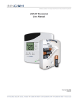
Installation/User Manual X529/e529
Part Numbers 02-9487-D & 01-9488.xxx
Revision 3.1, Issued 9/12/06
INNCOM international, inc.
Figures:
Figure 1. X529 Logic Board ............................................................................................................... 4
Figure 2. e529 Battery Thermostat .................................................................................................... 4
Figure 3. Housing and Mounting Plate............................................................................................... 6
Figure 4. Snap-Track ......................................................................................................................... 7
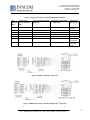
Figure 5. Mod Truss Screws .............................................................................................................. 7
Figure 6. Cards in the Snap Track ..................................................................................................... 7
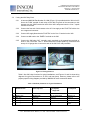
Figure 7. Installing the X529/X06 Relay Pack Inside the PTAC/FCU Housing ................................. 8
Figure 8. X06 Dimensions.................................................................................................................. 8
Figure 9. Typical Installation .............................................................................................................. 9
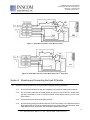
Figure 10. RB05 Connected to 3-Fan FCU........................................................................................ 10
Figure 11. RB05 Connected to 2-Fan Heat Pump with 2nd Stage Heat............................................. 10
Figure 12. Wiring Harnesses.............................................................................................................. 11
Figure 13. X529/X06 Connected to 3-Fan Heat/Cool FCU................................................................ 12
Figure 14. X529/X06 Connected to 2-Fan Heat Pump with 2nd Stage Heat...................................... 12
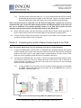
Figure 15. Door Position Input Through RB05 IN1 (RB05 H1 Pin 8 and Pin 1) ................................ 13
Figure 16. Door Position Input through X06 IN1 (X06 H2 Pin 4 and Pin 1)....................................... 14
Figure 17. Connecting Switch Leads to X529 IN2 and IN3 ............................................................... 14
Figure 18. X529 LEDs........................................................................................................................ 18
Figure 19. X529 Headers and Pinouts............................................................................................... 19
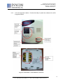
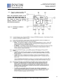
Figure 20. e529 Windows, Control Buttons, and Sensors ................................................................. 21
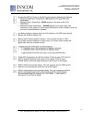
Figure 21. e529 Display and Button Functions .................................................................................. 22
Figure E-1. ES-1 H9 Header .............................................................................................................. 32
Tables:
Table 1. Wiring Color Codes for Typical RB05/X529 Installation ...................................................... 10
Table 2. X06 Relay Functions for Typical Installations ...................................................................... 11
Table 3. Typical Configurations ......................................................................................................... 19
Table 4. Revision History ................................................................................................................... 38
Appendixes:
Appendix A – e529/X529 Service Parameter Mode…………………………………………………….. 24
Appendix B – Setting the Address of the X529 Controller via the e529 Thermostat………………… 26
Appendix C – Changing the P5 Channel of the e529 and X529……………………………………….. 29
Appendix D – Using the Palm Sneezer to Test and Troubleshoot e529/X529 Installations………… 30
Appendix E – Using the ES-1 Flash Memory Module with the e529/X529…………………………… 32
Appendix F – Obtaining Standalone ETM Runtime Data from the X529……………………………… 34
Revision History…………………………………………………………………………………………… 36
3
277 · West Main Street· Niantic, CT · USA · 860-739-4468 · www.inncom.com