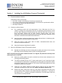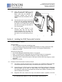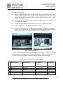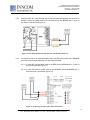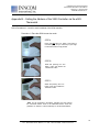
1
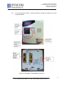
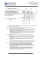
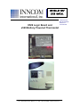
Installation/User Manual X529/e529
Part Numbers 02-9487-D & 01-9488.xxx
Revision 3.1, Issued 9/12/06
INNCOM international, inc.
1.3.5
Verify that the e529 display is now
showing information. If the display is
blank, verify that the batteries are
completely installed with the right
polarities and that the batteries are not
“dead.”
1.3.6
Hook the tabs at the top rear of the e529
housing into the matching depressions
at the top of mounting plate and rotate
the bottom of the e529 housing toward
the wall until it snaps into the place on
the mounting plate.
1.3.7
Secure the e529 housing to the
mounting plate with the two small
screws provided with the e529. The
screws thread into two small holes on
the bottom of the e529 housing (Figure
3).
Figure 3. Housing and Mounting Plate
Section 2 Installing the X529 Thermostat Controller
2.1
Required installation materials:
X529 with RB05:
• Two ½” long, #8 mod truss lath self-drilling screws
• 12”, 8-pin X529 low voltage harness (INNCOM Part Number 62-1449); provided with X529
• 8 wire nuts or “Dolphin” connectors sized to connect 16 to 22 gauge stranded wiring
• Drill and 1/16” drill bit
X529 with X06 Relay Pack:
• Four #5 self drilling pan-head Phillips screws; ¾” long typical
• Eight ¼” quick-disconnect female spade lug connectors that accept 14-16 gauge wire
• X06 Relay Wiring Harness, INNCOM Part Number 62-1498; provided with X06
• 14-16 gauge wire to connect AC power to X06 and to connect X06 relay outputs to HVAC
equipment
• Drill and 1/16” drill bit
2.2
Position the X529 Thermostat Controller as follows:
2.2.1
The X529 is typically mounted inside the housing of the PTAC/FCU being controlled.
Avoid mounting the X529 near moving or excessively warm parts of the PTAC/FCU.
2.2.2
Connections to the X529 for power, control signals, and the Eye5 module are made using
several headers on the X529 PC board. Make sure sufficient space is available
surrounding the X529 board and the particular interface board (RB05 or X05/X06) so that
these connections can be made.
2.2.3
Diagnostic LED’s are located on the top of the X529 PC board. If possible, mount the
6
277 · West Main Street· Niantic, CT · USA · 860-739-4468 · www.inncom.com