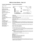
1
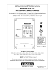
2.4
SERVICE WARNING!
Do not service equipment with voltage applied! The unit can be the
source of fatal electrical shocks! To avoid shock hazard,
disconnect main power and control power before working on the
unit. Warning labels must be attached to terminals, enclosure and
control panel to meet local codes. Use Lock Out tags such as the
one shown when servicing equipment.
2.5
Mounting and Cleaning
When drilling or punching holes in the enclosure, cover the electrical
assembly to prevent metal filings from becoming lodged in areas which
can cause clearance reduction or actual electrical shorts. After work is
complete, thoroughly clean, vacuum the area, and re-inspect the unit for
foreign material.
2.5.1 Clearances
Make sure there is sufficient clearance all around the unit for cooling,
wiring and maintenance purposes. To conserve panel space, the VMX
Series – BP models were designed for close vertical clearances of only
1 inch (25mm) on either side. A minimum horizontal clearance of 4”
(100 mm) on the top and bottom is necessary to maximize effective
airflow and cooling. Also the unit must be installed with its heat sink ribs
oriented vertically and running parallel to the mounting surface. Keep in
mind that these are minimums. Wiring may require more clearance,
particularly on the bottom.
1" minimum (25 mm)
4" minimum (100 mm)
VMX Series
Starter
4" minimum (100 mm)
1" minimum (25 mm)
Figure 2.5: VMX minimum mounting clearances
VMX Series Digital Solid State Soft Starter User Manual
6|Page