1
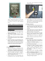
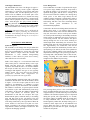
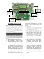
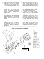
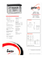
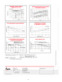
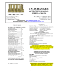
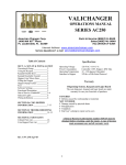
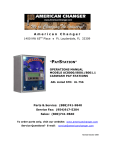
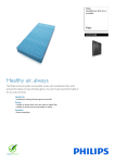
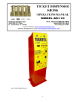
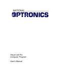
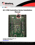
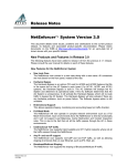
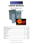
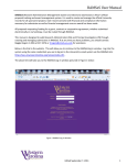
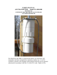
BATTERY-POWERED
CHANGER
MODEL AC400B
OPERATIONS MANUAL
American Changer Corp
1400 NW 65th Place
Ft. Lauderdale, FL 33309
Parts & Service: (888)741-9840
Sales: (800)741-9840
Fax: (954)917-5204
Internet Address: www.americanchanger.com
Service Questions?: E-mail: [email protected]
Table of Contents
Initial Setup & Installation
Battery Charging
Coin Hopper Information
Functional Description
Harness Connection Diagram
Programming Logic Board
Compact Hopper Parts
AC400B Cabinet Parts
Troubleshooting Guide
Battery Specifications
Specifications
2
2-3
3-4
4
5
5-6
6
7
8
9-10
Operating Voltage:
Battery Type:
Power Consumption:
12V DC
Sealed Lead-Acid, 12 Ah
Max.: 21 W
Battery Life:
Supplied Battery Charger:
Standby: 3.1 W
Sleep: 110 mW
4-6 Weeks on full charge
Charge: 14.8 – 15 Vdc, 550mA max.
Operating Temperature:
Float: 13.6 – 13.8 Vdc, 30mA max.
32 - 130 degrees Fahrenheit
Warranty
The AC400B, including its Bill Validator and Coin Dispenser, is
under warranty for a period of 6 months from the date of
purchase. The battery is under full-replacement warranty for a
period of 30 days from the date of purchase.
COVERED:
¥ Defects in workmanship or materials
NOT COVERED:
¥ Damage caused by physical abuse
¥ Misapplication
¥ Vandalism
¥ End user’s attempt to repair unit on his own
¥ Lack of cleaning/maintenance
It is the End User’s responsibility to clean & maintain all their
parts. Any unit coming in for repair requiring only a cleaning
will be charged a flat rate of $65.00 plus shipping and handling.
TO RETURN A PART OR UNIT FOR REPAIR, TO
ORDER A PART, OR FOR TECHNICAL
INFORMATION, PLEASE CALL TOLL FREE
(888) 741-9840
A Return Material Authorization number (RMA#) must be
obtained before returning a unit for repair. A copy of
invoices must accompany any and all warranty work.
Rev. UNCG-1A-F06 10.17.05
1
CHARGING THE BATTERY
SETUP AND INSTALLATION OF THE
BATTERY-POWERED CHANGER
When your AC400B arrives from the factory, the 12
Volt Sealed Lead Acid (SLA) battery supplied with the
unit may not be fully charged. So, in order to get the
most use out of your changer, charge the battery fully
before using the AC400B for the first time. You can use
either the supplied Battery Charger (ACC P/N
AC400.4) or another one, so long as it complies with
the charging methods detailed in the accompanying
battery specifications (refer to pages 9-10).
Unpacking:
Carefully remove the changer from the shipping box,
and open the door (the keys will be in the manila
envelope with this manual). The lock used on this unit
is a “screw-in” type, and will require several
counterclockwise turns of the key before it releases.
Inspect the interior closely for any shipping damage.
The coin hopper should be held in place with tie-wraps;
these are for shipping only, and should be cut and
removed. Remove the supplied charger from inside of
the hopper. The battery will already be unplugged from
the board at its white connector. Remove the battery
from the case, and charge it fully before using the
changer (refer to the CHARGING THE BATTERY
section of this manual for detailed instructions).
Refer to the following procedure to charge the battery if
using the supplied battery charger. If a different charger
is to be used, read the directions given here for
removing and reinstalling the battery, but consult the
charger’s manual for specific charging instructions.
1.
Perform a functional test of your new changer before
making the final installation. But make sure the battery
is fully charged, and the coin hopper has enough coins
in it to cover the two square plates at the bottom of the
coin bowl before attempting to use the changer.
2.
Securing the AC400B to a Base Kit (Optional)
1. Remove the battery and the coin hopper from
inside of the cabinet (see instructions following).
2. Set the cabinet on top of the base.
3. Install the 4 bolts, 1/4" x 1-1/2”, through the inside
bottom of the changer into the base and tighten.
4. CAUTION!: When installing a changer with an
attached base, it is recommended that the base be
bolted securely to the ground, or other stationary
object. This is to prevent the unit from tipping and
possibly causing damage or injury.
Disconnect the battery from the Logic Board’s
power harness at the white connector located near
the battery’s terminals (refer to Figure 2).
Loosen the wing nut, and remove the bracket
holding the battery in place (refer to Figure 2).
1.
2.
FIGURE 2 – BATTERY CONNECTOR & BRACKET
3.
HOPPER
PLATES
4.
5.
FIGURE 1 – AC400B CABINET INTERIOR VIEW
2
Grasp the battery’s loop handle, and pull the
battery up and out of the cabinet.
NOTE: The battery should be charged in a wellventilated area. Dot not charge the battery in an
enclosed space.
With the battery charger unplugged, connect its
white connector to its counterpart mating connector
fastened to the battery terminals. If your charger
has alligator clips, attach the black one to the
negative (-) battery terminal, and the red one to the
positive (+) terminal. The clips must make contact
with the metal terminal tabs, so loosen, but do not
remove, the blue connectors if necessary.
Once the charger is properly connected to the
battery, plug it in to any 120 Volt AC outlet to
begin charging. During charging, the RED
“Charging” LED on the battery charger will be ON
solid. Continue charging until the GREEN
“Charged” LED turns ON solid, at which time
charging is complete (refer to Figure 3).
the coin chute. This will disable the lock holding
the hopper in place.
PUSH
FIGURE 3 – SUPPLIED BATTERY CHARGER
6.
7.
8.
FIGURE 4 – COIN HOPPER REMOVAL
NOTE: Charging times depend on the extent that
the battery has been discharged, and may take up
to 24 hours or more for a 100% discharged
battery.
4.
CAUTION!: NEVER store a discharged battery
for any length of time, as this leads to a condition
inside the battery called sufation, which may cause
a permanent loss of battery capacity. ALWAYS
fully charge the battery immediately after use,
recharging as often as is practicable, in order to
prolong its service life.
Coin Hopper Installation:
1. To reinstall the hopper, hold it upright and line up
the three keyholes on its bottom with the three
plugs on top of the hopper plate. Make sure it is
oriented so that the coin chute faces toward the
front door.
2. Lower it until its base rests on the hopper plate
with the plugs inside of the keyholes. Pull the coin
hopper forward until it ‘clicks’ into place.
3. Reconnect the hopper wiring harness to the Logic
Board; be sure to attach both connectors. NOTE:
The Logic Board connector pins are polarized
(unidirectional). The proper way to attach the
harness connectors is so the wires coming from
them are running away from the board, not over it.
The supplied charger can remain connected to the
battery and plugged in for any length of time
without harm to the battery.
When charging is complete, unplug the charger
from the wall, and detach its connector from the
battery.
Lift the battery back into the cabinet, and replace
the metal bracket that holds it in place. Retighten
the wing nut.
Reconnect the battery to the Logic Board’s power
harness at the white connector located near the
battery’s terminals. The connector is polarized, so
it will only fit the correct way, which is to connect
the red +12VDC wires to each other, and the black
ground wires to each other (refer to Figure 2).
While holding the lever down, push the hopper
back, toward the rear wall of the unit, until it stops.
Release the lever, and pull the hopper up off of its
plate, and forward out of the machine.
Filling the Coin Hopper:
♦ The AC400B will not operate if the coin hopper is
empty. There must be coins covering the two
square plates at the bottom of the coin bowl (refer
to Figure 1) for the changer to activate.
♦ The hopper’s bowl can be filled with coins while
inside or outside of the changer.
♦ Use only the coins that were specified at the time
of purchase, e.g. quarters. To dispense a different
size coin or token, a different hopper will be
needed. Contact American Changer if you have
any questions, or would like to convert to a
different hopper.
♦ The capacity of the coin hopper, containing
quarters, is 500 coins +/- 10% due to the random
nature of coin piling inside of the bowl.
♦ Take care when filling the hopper to prevent any
bent coins or foreign objects from entering the coin
bowl. These will cause the coin hopper to jam,
rendering the changer inoperable.
COIN HOPPER INFORMATION
Coin Hopper Removal:
1. Make sure that power is disconnected before
touching any wiring harnesses connected to the
board. Do this by uncoupling the white connectors
near the battery’s terminals, if not already done so.
2. Disconnect the hopper wiring harness (AC400.6H) from the Main Logic Board. It should be
connected in two places on the board (refer to
Figure 6); unplug both connectors.
3. Gently push down on the small plastic lever
protruding from the base of the hopper, underneath
3
Power Management:
The AC400B has two modes of operation with respect
to its power usage, Standby and Sleep. Sleep mode is
the mode the changer is in when there is no changing
operation taking place, and the unit is “waiting” for a
bill to be inserted into the validator slot. During Sleep
mode, power to the Main Logic Board, the bill
validator, and the coin hopper is turned OFF in order to
conserve the battery. Only one part of the system is ON
and running, and that is the Power Switching Board,
which
controls
power
distribution
to
the
aforementioned peripherals.
Coin Hopper Maintenance:
The maintainable life of the Coin Hopper is approx. 3
million coins, assuming certain regular component
replacement, i.e. replace the ejector fingers and spring
every 500,000 coins, and the adjuster plate every 1
million coins. In addition, all accessible parts of the
coin route should be cleaned every 50,000 coins using
one of the following approved cleaners: compressed air
dusters, lint-free polyester swabs, or soft lint-free cloths
with a mild detergent. No spray solvents should be
used. Pay particular attention to the disc bed assembly
and the optical sensor at the coin exit, as dirt buildup
may cause unreliable coin counting (refer to Figure 7).
Connected to the Power Switching Board, and also ON
during Sleep mode, is an infrared optical sensor.
Mounted on the inside of the front door behind the bill
entry slot, the sensor is used to “wake up” the machine
out of Sleep mode and bring it into Standby mode (the
sensor location is indicated by the arrows in Figure 5).
A bill being inserted into the machine first passes
directly through the slot in the sensor, breaking its
infrared light beam. Immediately, the electronics enter
Standby mode, where all of the peripherals are powered
ON. Approximately one second later, after the bill
acceptor has finished its initialization procedure with a
quick pulsing of its motors, the bill can be pulled into
the acceptor, validated, and the correct amount of coins
dispensed from the hopper. The power-up procedure is
fast enough that a bill should be able to enter the slot,
turning everything ON, and continue uninterrupted
straight into the validator for processing.
WARNING!: Disconnect battery power, and detach the
Hopper Harness before performing any maintenance
procedure. Avoid inhaling any coin dust that may have
accumulated in the hopper during use, as it may be a
respiratory hazard.
FUNCTIONAL DESCRIPTION
System Description:
The AC400B is a bill changer that accepts dollar bills
and pays out four quarters in its standard configuration,
and is also programmable for various other coin/token
payouts. What is unique about this machine, that
differentiates it from standard change-making
machines, is that it draws its power from a battery,
rather than from an AC wall outlet.
Inside of the changer is a 12-Volt Sealed Lead-Acid
(SLA) battery that is connected directly to the Logic
Board, and that powers the AC400B’s complete
operation. Also inside the unit is a 12-Volt bill validator
that accepts $1 bills only, and a 12-Volt “Compact”
coin hopper that dispenses one type of coin, typically
quarters. NOTE: This section describes the standardconfiguration AC400B. Other configurations are
possible if specified at the time of purchase.
A typical changing operation begins with a bill being
inserted into the slot on the front of the machine, shown
in Figure 5. The bill acceptor pulls the bill in and
examines it for authenticity, or “validates” it, before
pulling it all the way into the machine. The AC400B’s
bill validator is stackerless, so upon acceptance the bill
is ejected into a “pile” that will harmlessly form on top
of the battery. At this point, the validator communicates
to the Logic Board, via electronic pulses, the
denomination of bill that was accepted. The Logic
Board reads the pulses, credits the money to its running
total, and then turns on the coin hopper. The coin
hopper immediately begins to dispense coins, with the
count being monitored by the Logic Board. When the
correct number of coins have been paid out of the
hopper, according to the settings programmed in the
Logic Board’s software, the hopper is turned off. This
completes the changing operation.
FIGURE 5 – AC400B FRONT, BILL ENTRY SLOT
The powering-down process is also controlled by the
Power Switching Board, and occurs after a timed delay
of approximately 11 seconds following a successful bill
validation. The standard 4-quarter payout is dispensed
during this period, after approximately 2-3 seconds,
leaving the changer in Standby mode for enough time
to accept additional bills. If the sensor’s beam is
blocked again by another bill, the delay timing cycle is
restarted to allow ample time for the additional coin
payout. When the timer is allowed to run out, all
peripherals are powered OFF once again, returning the
machine to Sleep mode.
4
COIN HOPPER
HARNESS
(AC400.6-H)
CONNECTORS
OPTICAL SENSOR
HARNESS
(AC400.5-H)
CONNECTOR
UP
DOWN
SELECT
VALIDATOR
HARNESS
(AC400.7-H)
CONNECTORS
POWER SUPPLY
HARNESS
(AC400.10-H)
CONNECTOR
FIGURE 6 – HARNESS CONNECTION DIAGRAM
you both hands to do the programming. Any method
that blocks the sensor for an indefinite amount of time
will work.
PROGRAMMING THE LOGIC BOARD
NOTE: The Logic Board arrives pre-programmed to
the settings specified at the time of purchase, and does
NOT need to be programmed under normal
circumstances. The purpose of this section is to restore
the programming for a standard 4-quarter payout, in
case a failure or a self-programming attempt has
corrupted the original settings to where the changer
does not operate as desired.
Programming Steps:
1. With the power ON, locate the three programming
buttons, “UP”, “DOWN”, and “SELECT”, on the
Main Logic Board (refer to Figure 6).
2. If not already there, wait until the board’s LCD
screen is displaying the running bill count, which
appears as a 5-digit number in the top right corner.
3. Press the SELECT button once to enter
Programming Mode. A screen should be displayed
showing a list of menus (Bills, Payout, …) with an
arrow on the left side of the screen pointing to
“Bills”.
4. Press the DOWN button twice to move the arrow
down to the “Hardware” menu, and then press the
SELECT button once to enter it.
5. When the Hardware menu is displayed (Hoppers,
Coin Acceptor, …) enter the “Hoppers” submenu
by pressing the SELECT button once, while the
arrow is pointing to it.
6. Inside of the “Hoppers” submenu, press the
DOWN button as many times as is needed to
scroll down the list of menu options until
“Compact” is displayed. Press the SELECT button
once to choose “Compact”. The screen should
then return to the initial bill count screen, the
choice having been saved in the board’s memory.
7. Go back into the “Hardware” menu by repeating
instructions 3 and 4. Once inside, press the
DOWN button once to move the arrow down to
the “Coin Acceptor” submenu, and then press
SELECT.
If you would like to reprogram your changer’s payout
settings to something other than four quarters, please
contact American Changer Technical Support for
assistance with the procedure (phone numbers and email addresses can be found on the front page of this
manual).
Changer Preparation:
1. Open the changer door and inspect the interior.
2. The changer should be configured for normal
operation, with the battery and all peripheral
harnesses connected. Make sure there are coins in
the hopper, at least enough to cover the two square
plates at the bottom of the coin bowl.
3. Using a small object, a coin or a strip of paper will
work, block the optical sensor beam (refer to
figure 5) to turn power ON to the Logic Board and
peripherals. The power needs to be on for an
extended time to complete this procedure, so the
beam needs to be continually blocked. You can
hold a coin in place with one hand while
programming with the other, or fold a piece of
paper in such a way as to be wedged into the slot
without being drawn into the bill validator, leaving
5
12. When the initial bill count screen again returns, reInside of the “Coin Acceptor” submenu, press the
enter the “Hardware” submenu for a fifth, and
DOWN button as many times as is needed to
final, time by repeating instructions 3 and 4. This
scroll down the list of menu options until “None!”
time, scroll down using the DOWN button until
is displayed. Press the SELECT button once to
the arrow points to the “Mode” submenu; press
choose “None!”. The screen should then return to
SELECT once to enter it.
the initial bill count screen, the choice having been
13. The “Mode” submenu has many choices, but just
saved in the board’s memory.
continue scrolling DOWN until the “S Changer”
9. Re-enter the “Hardware” menu by repeating
option is highlighted. Press SELECT to choose it,
instructions 3 and 4. Then, scroll down through
save it, and return to the bill count screen.
the options, using the DOWN button, until the
14. As a final step, press the SELECT button once,
“Validator” submenu is highlighted. Press
from the bill count screen, to enter Programming
SELECT to enter it.
Mode. This time, press DOWN only once to
10. When the Validator submenu has opened, scroll
highlight “Payout”, and then press SELECT.
down with the DOWN button, if necessary, and
15. The “Payout” screen will open up, and a dollar
SELECT “MDB”; this enters the “MDB”
amount, in dollars and cents, will be displayed.
submenu. Inside of the “MDB” submenu, scroll
Use either the UP button to increase, or the
DOWN until you see the option “None!”, and then
DOWN button to decrease, the amount shown on
SELECT it. The bill count screen will then be
the screen until it reads “$0.25”, signifying
displayed.
quarters in the hopper. When the amount is
11. Re-enter the “Validator” submenu by repeating
exactly “$0.25”, press the SELECT button once to
instruction number 9. This time, scroll DOWN
accept it, and return to the bill count screen.
and press SELECT when “Pulse” is highlighted.
16. Programming the Logic Board for a 4-quarter
Inside of the “Pulse” submenu, scroll DOWN, and
payout is complete at this point, and the optical
SELECT “1”. When the next screen, “Enable”,
sensor / bill slot obstruction can be removed,
has opened, scroll DOWN, if necessary, to
allowing the board to power OFF after 11 seconds.
highlight “Low”, and then press SELECT to
choose this option.
_________________________________________________________________________________________________
8.
MONEY CONTROLS “COMPACT” COIN HOPPER
Optical Sensor –
Coin Eject Path
FIGURE 7 – HOPPER PARTS DIAGRAM
6
AC400B CABINET PARTS LIST
#1
#2
#3
#7
#10
#8
#4
#5
#9
#6
#1.
#2.
#3.
#4.
#5.
#6.
#7.
#8.
#9.
ACC PART NUMBER
AC5010.2
AC1065
AC400.8
AC300-B.1
AC4081
AC9011
AC5040.5
AC400.4
AC3080
AC400.9-H
AC400.5-H
AC400.7-H
AC400.10-H
AC400.6-H
#10. AC400.11-H
DESCRIPTION
AC400B CABINET, COMPLETE W/ DOOR & LOCK BRACKET
MAIN LOGIC BOARD W/ LCD DISPLAY
POWER SWITCHING BOARD
12 VOLT, SEALED LEAD-ACID, RECHARGEABLE BATTERY
FULL-FACE LEXAN FRONT
PYRAMID XLC-5200 BILL VALIDATOR, STACKERLESS
MONEY CONTROLS COMPACT HOPPER, 12 VOLT
BATTERY CHARGER, FOR 12 VOLT SLA BATTERY
CABINET LOCK AND KEY
HARNESSES (SEE FIGURE 6 FOR LOCATIONS)
BATTERY CHARGER HARNESS
OPTEK OPB917B OPTICAL SENSOR W/ HARNESS
PYRAMID XLC-5200 VALIDATOR HARNESS
AC400B POWER SUPPLY HARNESS
MONEY CONTROLS COMPACT HOPPER HARNESS
AC400B BATTERY TERMINAL HARNESS
7
AC400B TROUBLESHOOTING GUIDE
To use this Troubleshooting Guide, locate the problem on the left-hand side,
and then follow the solution suggestions on the right-hand side.
PROBLEM:
SOLUTION:
1.
2.
3.
A. The changer will not turn
ON.
4.
5.
6.
7.
8.
1.
2.
B. The changer is turning ON,
but it will not pay out any
coins.
3.
4.
5.
6.
1.
C. The changer is operating,
but it is not paying out the
correct amount of coins.
2.
3.
FOR TECHNICAL SUPPORT, OR
TO OBTAIN A RETURN
MERCHANDISE
AUTHORIZATION (RMA)
NUMBER, CALL (888) 741-9840
Check the Power Supply Harness (AC400.10-H) and the Optical Sensor
Harness (AC400.5-H) to ensure that they are both securely attached to their
correct circuit board connectors (refer to Figure 6).
Check the Battery Terminal Harness’ (AC400.11-H) blue right-angle
connectors to ensure they are securely attached to the battery’s terminals.
The coin hopper is out of coins. The changer will not turn on if there is a
low coin condition in the coin hopper; fill the hopper bowl with at least
enough coins to cover the two square plates at its bottom.
Check the hopper bowl’s square plates to see if they are excessively dirty or
tarnished. If so, they should be cleaned with a piece of steel wool,
sandpaper, or some other mild abrasive until they are shiny.
The charge on the battery is low. The changer is designed to cease operation
when the battery reaches 10.5V or below in order to prevent overdischarging. Charge the battery fully before attempting to reuse the changer.
One or more of the harnesses mentioned in solutions 1 and 2, or the
Compact Hopper Harness (AC400.6-H) has gone bad. Remove them and use
a DMM or ohmmeter to check for continuity.
The Power Switching Board (AC400.8) has failed.
The Main Logic Board (AC1065) has failed.
The Logic Board’s software has been altered or corrupted. Follow the
instructions in PROGRAMMING THE LOGIC BOARD on pages 5-6 of this
manual to restore the board’s initial software settings.
Check both the Pyramid Validator Harness (AC400.7-H) and the Compact
Hopper Harness (AC400.6-H) to ensure that all connectors are securely and
correctly attached to the circuit boards.
One or both of the harnesses mentioned in solution number 2 have gone bad.
Remove them and use a DMM or ohmmeter to check for continuity.
The Compact Hopper (AC5040.5) has jammed. Empty the coin bowl,
remove the jam, and check the bowl for any other bent coins or foreign
objects before refilling the bowl.
The Validator (AC9011) has malfunctioned; refer to its user’s manual. Or,
the Validator has failed.
The Compact Hopper (AC5040.5) has failed.
The Logic Board’s software has been altered or corrupted. Follow the
instructions in PROGRAMMING THE LOGIC BOARD on pages 5-6 of this
manual to restore the board’s initial software settings.
The Compact Hopper’s optical sensor located in the coin eject path is
obscured by dirt. Clean the sensor and the exit path, following the guidelines
listed in the Maintenance procedure on page 4.
The Validator programming may have been corrupted. Contact American
Changer Technical Support for assistance.
ANY REPAIR RETURNED WITHOUT AN
RMA NUMBER WILL BE REFUSED!
8
9
10