1
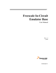
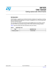
HCS08 Full Chip Simulation
Peripheral Modules Commands
Serial Communications Interface Module
In Full Chip Simulation, this module will simulate all functionality of the Serial Peripheral
Interface (SPI) module including:
• Flag polling
• Interrupt enabled mode
• 8- or 9-bit length data codes
• Odd and even parity modes
• Transmission and reception of external data
Full Chip Simulation (FCS) mode uses the buffered input/output structure to simulate SCI
inputs. The user can queue up to 256 data values into the input buffer. The output buffer of
the SCI module can also hold 256 output values. To queue the SCI Input Data, one should
use the SCDI <n> command in the command prompt. If <n> (the data parameter) is given,
the value is placed into the next slot in the input buffer. Otherwise, if no parameter is
provided, a window is displayed with the input buffer values. Input values can be entered
while the window is open. An arrow points to the value that will be used next as input to
the SCI. The data from the SCI input buffer is written to the SCI data register once the SCI
module has been turned on and is properly configured for receiving data from an external
serial device. Once the simulation of the data transmission is over, the arrow moves to the
next value in the SCI IN Buffer.
Figure 20.26 SCI IN Buffer Display
SCI Data Output Buffer simulation allows the user to gain access to the past 256 SCI data
values transmitted out of the module. To bring up the SCI OUT buffer dialog, the SCDO
command should be used.
524
HC(S)08/RS08 Debugger Manual