1
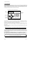
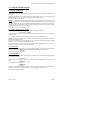
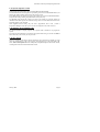
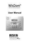
2000 SERIES
DIAGNOSTIC ALARM
CONTROL SYSTEM
OPERATING
INSTRUCTIONS
MODELS:
2300
2500
2700
This information is relevant to systems fitted with
Issue 4.1 (or later) Master Keypad Software,
also to Networked Systems fitted with
issue 7.1 (or later) Gateway Software.
Castle Care-Tech Ltd.
2000 Series Alarm System Operating Instructions
Contents:
1. Introduction
1.1
Terms Used
1.2
Understanding the 2000 Keypad
1.3
Menu Based
1.4
Product Type
2. Using the Alarm System
3.
2.1
Setting the System
2.2
Completing the Setting Procedure
2.3
What to do if there is a Fault on Exit
2.4
Anti-Mask Protection
2.5
Unsetting the System
2.6
How to Silence an Alarm
2.7
The 'Chime' Facility
2.8
System In Use
2.9
The Keypad PA Alarm
2.10
The 'Code Guessing' Alarm
2.11
Telecom Line Fault
2.12
Keyswitch operation.
2.13
Doorbell Facility
2.14
System Operator Codes
2.15
Engineer Programming Code
2.16
Fire Alarm
Other Indications
3.1
Engineer Reset Needed
4. System Manager Functions
4.1
Changing Operator Codes
4.2
Other Manager Menu Functions
4.3
Omitting Zones
4.4
Exit Manager Mode
January 2000
Page 1
Castle Care-Tech Ltd.
1. Introduction
The Care-Tech 2 000 Series diagnostic control unit has been designed and manufactured in
England to provide the facilities necessary to form the heart of a sophisticated alarm system
complying with British Standard BS4737, for the protection of persons and property. Many of the
facilities are programmed by the installing company, who will be able to advise you on the
availability of certain of the features referred to in this manual.
The Care-Tech 2000 Control Keypad
The
Display
Area Set
Indicators
AC Power
Indicator
System Ready
09:56:34 14/10
A
B
~
C
D
1
2
3
A
4
5
6
B
7
8
9
C
*
0
#
D
NO
Operating
Keypad
YES
CARE-TECH 2000
The system consists of one or more units monitoring the detectors, and providing the outputs to
meet the security specification for the premises being protected. It is controlled by one or more
keypad units with text displays to guide the user through operation.
The system is powered from the mains supply, and is fitted with a rechargeable battery to ensure
that the system continues to function normally, for a minimum of eight hours, during a mains
power failure.
Any questions you may have in relation to the alarm system should be addressed to your Alarm
Installation Company.
BEFORE ATTEMPTING TO USE THE ALARM SYSTEM, PLEASE READ AND
THOROUGHLY FAMILIARISE YOURSELF WITH THESE INSTRUCTIONS
Because of the almost infinite combination of options programmable in the 2000 system, it is
impractical to include specific details of all available combinations in this manual. Certain aspects
of setting procedure for example may vary from day to day according to other actions carried out
prior to your operation.
It is therefore very important that you closely follow the directions on
the keypad display rather than memorise a set pattern of key entries.
Please ensure that any queries you may have are adequately clarified by your installing company.
NOTE: Castle Care-Tech Ltd. reserve the right to change the specification of this system
at any time in the interests of product improvement.
Page 2
Iss: 11a
2000 Series Alarm System Operating Instructions
1.1 Terms Used
Certain terms used to describe features and Operation of the system may be unfamiliar. The
principal ones are as follows:
DAY MODE
The 'normal' state of the alarm system whilst the premises are
occupied, and the alarm switched 'OFF.' 'Personal Attack' facilities
remain functional, and the system will continue to monitor itself for
evidence of tampering. Also known as 'UNSET' or 'OPEN'
SWITCH ON
The action of activating, or 'SETTING' the alarm system, whether by
use of the keypad or keyswitch.
SET
The condition of the alarm system when armed, after the switching on
process has been completed - ie after the completion of the exit time.
Also known as 'CLOSED.'
AREA SET
The condition of the alarm system when a pre-programmed portion of
the system is not armed - for example when setting the system at night
whilst still in the premises.
EXIT TIME
The time delay permitted after switching the system on and before it
becomes armed - during which you must leave the premises, and
close the final exit door.
ENTRY TIME
The time delay permitted by the system after entering by the
authorised route, and during which the system must be switched off,
or an alarm will sound.
ENTRY-EXIT
ROUTE
The portion of the alarm system linked to the Exit and Entry timers,
through which exit and entry must be made.
WALK THROUGH Part of the Entry Exit route which, in certain operating modes, will
DETECTOR
trigger an immediate, rather than delayed, alarm if triggered without
first triggering the initial entry detector.
ZONE or CIRCUIT A division of the system which is separately identified in the
indications at the control.
ZONE or
CIRCUIT FAULT
Condition of one of the zones when one (or more) detectors are not
clear, thus preventing the system from being 'set' - eg an open door.
ZONE OMISSION The facility to disable an individual zone (or zones) whilst setting the
system
SYSTEM FAULT
An incorrect electrical condition which may impair the correct
operation of the system - refer to these instructions for action
required.
TAMPER FAULT
A fault existing in the wiring, or securing of the housing of part of the
system, preventing normal operation.
PERSONAL
ATTACK (PA)
or DURESS
An alarm generated deliberately, to summon assistance if being
attacked, operative whether system is switched on or not. If the
system is connected to an Alarm Receiving Centre, this alarm may be
silent.
REMOTE
SIGNALLING
The facility (if fitted) for the system to automatically communicate by
telephone line with a remote Alarm Receiving Centre to initiate a call
to the police.
January 2000
Page 3
Castle Care-Tech Ltd.
1.2 Understanding the 2000 Keypad
The keypad that operates your alarm system has four major parts:
1.2.1 The Display
The liquid crystal display (LCD) indicates the condition of your alarm system, typically
System Ready
09:56:35 14/10
The 'System Ready' message may have been reprogrammed to an alternative by your installing
company. References to 'System Ready' in this manual refer to the text message shown when the
system is in its normal state
Any information that requires your attention will be displayed and stated quite clearly. The
display is back-lit for maximum legibility. When the system is set, the light will extinguish, and
will re-light at the next keypress. The light will also extinguish to conserve power during a mains
power cut, except for the period that the keypad is in use.
1.2.2 The Numeric Keypad
The 10 numeric keys are for entering your code so that you may set or unset the system, or enter
other information on request.
Always enter your code carefully and deliberately.
1.2.3 The YES (#) and NO (*) Keys
These keys allow you to access additional functions of the system, as well as to respond to the
simple choices presented; for example:
Set System?
Note that some keypads may not include the 'YES' and 'NO' legends. In this case, substitute '#' for
'YES', and '*' for 'NO'
1.2.4 The A, B, C and D Keys
These keys allow you to set and unset parts of your alarm system, for example AREA A could be
the first floor.
1.3 Menu Based
The Care-Tech 2000 System operation is MENU BASED. You can scroll around the MENU by
simply pressing the NO key.
System Ready
(NO key)
Set System?
(NO key)
Manager Menu
(NO key)
System Ready
If the system is left with 'SET SYSTEM?' or 'MANAGER MENU' on the display for 60 seconds,
it will automatically return to 'SYSTEM READY.'
1.4 Product Type
To ascertain whether your system is a Care-Tech 2300, 2500 or 2700, press the 'A' key whilst the
'System Ready' message is showing. The display will show
2500 iD v 4.1
Released Jan 00
Page 4
or the equivalent for your system.
Iss: 11a
2000 Series Alarm System Operating Instructions
2. Using the Alarm System
2.1 Setting the System
Before attempting to set the system, check that you have secured all the appropriate doors and
windows.
Check that the display shows 'System Ready.' If a fault message is shown (see section 5) take the
appropriate action, or use the 'NO' key to scroll till 'System Ready' shows.
Key in your full code (eg 1234).
NOTE the indications on the display, and the exact key entry sequence after entering your code
will vary according to the options programmed into the system, whether any area or areas of the
system are already set, etc. Do NOT therefore attempt to memorise a key sequence to be entered
without reference to the display. Note the options offered by the display, and respond to them
progressively until the exit tone commences.
The options which may be available are:
2.1.1 Setting with 'Select Areas' Option
If the facility to 'Select Areas' has been programmed , the display will show
Select Areas [ABCD]*
To change the areas being set, use the 'A,B,C,D' keys to change the status shown on the display,
then press 'YES'
* - The display will show the maximum areas which your code is authorised to set.
NOTE: Press the keys for the areas you wish to set; what is displayed in the window is what you
will SET when pressing 'YES'
If an area or area on the system are already set, the system will first present the option to 'Unset
System?' - press 'NO' to move to 'Set System?' option.
Once the 'YES' key is pressed, the system may briefly show 'Please Wait' (see 2.4) and then
commence exit time as above, or move to next menu.
2.1.2 Silent Setting
If this facility has been programmed by your installing company, you have the option of setting
the system silently, for example to avoid disturbing sleeping members of the family.
Silent Set?
Press YES key to select this option
2.1.4 Omitting Zones
It is possible to omit individual zones at the time of setting, if this option has been programmed by
your installing company.
Omit Zones?
Press YES key if you wish to omit a zone, then key in the zone number eg 09, the display will
show
OMITTED:
09
This display will then change to
OMITTED : _ _
Lounge
Additional zone numbers may be entered in a similar way, and the identities will scroll through in
sequence. A zone may be removed from the 'omit' list by entering its number again.
Press YES to complete selection.
January 2000
Page 5
Castle Care-Tech Ltd.
2.2 Completing the exit procedure
Once all available options have been accepted, the display will show
Leave by Exit Route
The exit tone will commence, and, if the system is programmed for 'Timed' exit, the Exit time will
display, and count down to zero.
Leave the building by the permitted route and complete the setting procedure by whatever means
are programmed. This may be by operating a 'PUSH TO SET' button outside the premises, by
the action of locking the final door, or may be automatic when a programmed timer expires.
Check that the tone is steady before activating the 'Push to Set' button, and that it ceases
before leaving.
When you have completed the exit procedure, the system is armed, and the keypad will display
'System Ready' with the backlight switched off.
2.3 What to do if there is a Fault on Exit
If instead of a continuous exit tone, you have an interrupted tone, look at the keypad display,
which will locate the possible fault - eg:
Cannot Set [02]
Zone 02
If the fault is part of your exit route (eg hallway PIR detector, or front door), this is normal, and
you may proceed with your exit procedure, being sure to close all necessary doors on the way out.
The presence of an open detector will prevent the system from setting, and automatically extend a
programmed exit time
If the fault is an open door or window elsewhere, abort the setting procedure before going to
close it.
When the final door is closed, and the detectors have settled, the tone will be continuous, and then
stop when the setting procedure is completed. Any interrupted tone continuing means that the
system has not set. You must re-enter the building, key in your code, and correct the problem.
NOTE: If a 'Push to Set' button is activated before the tone becomes steady, the signal will be
'stored' until the fault clears, and then set the system.
2.4 Anti-Mask Protection
If the system has been programmed to do so, certain detectors will be checked whilst the system is
unset, to ensure that they continue to function correctly. When setting, the display will show
'Please Wait' (following the 'Select Areas' menu) briefly whilst this check is being completed. If
any of such detectors have NOT operated whilst the system was unset, then the system will 'chime'
repeatedly, and indicate:
Not Tested [12]
Stores
If more than one detector is affected, the zone names will scroll sequentially.
If you walk within the field of these detectors, they will disappear from the list, and the display
will show
All Zones Tested
.... Press YES Key
On pressing the 'YES (#) key, the setting procedure will be completed.
If the 'YES' key is pressed without testing the detectors, the check will be cancelled and the system
will set, with details of the untested detectors being recorded in the system logs.
Alternatively, pressing the 'NO' (*) key will abort the setting procedure, allowing you to go and
check the detectors before trying again.
Page 6
Iss: 11a
2000 Series Alarm System Operating Instructions
2.5 Unsetting the System
Enter via the authorised entry route, go to the keypad and enter the following commands (the
ENTRY TONE will continue to sound until the entry procedure is complete):
Enter User Code
Key in your full code - eg 1234
Unset Areas [ABCD]
YES key
System Ready
Alarm system is UNSET.
If the alarm system is PART ARMED when you enter the building:
Enter User Code
Key in your full code - eg 1234
Unset System?
YES key
(Pressing the NO key will provide the option to set
additional areas.)
Unset Areas: [ABC ]
Press 'YES' key, or key in areas you wish to
UNSET - ie what is displayed in the window is
what you will unset.
System Ready
Alarm system is UNSET
If being forced by an intruder to unset the system, this can be done with a special 'DURESS'
code. This will unset the system in exactly the same way, but will generate a silent alarm signal
to an Alarm Receiving Centre (if connected).
2.6 How to Silence an Alarm
If an alarm occurs during the day (due to wiring failure/ personal attack switch operated/ fire), go
to the nearest keypad. Do not panic, deliberately key in your code as requested:
Enter User
Code: - - - First Alarm [xx]
PA BUTTON
Deal with the cause of the alarm, then press YES to return the system to normal.
If the system alarms whilst the system is set, the alarm will automatically silence as the system is
unset (as above). The system is designed to automatically silence an alarm after a pre-set time,
and may be programmed to automatically reset itself at that point.
Should an alarm occur whilst the system is fully set, it may be silenced by ANY code valid for the
system. If the code is not valid for use with that area, the area will remain set, and able to generate
a further alarm. If the system is partially set, a code valid for the area in which the alarm is
generated must be used.
2.7 The Chime facility
If the system has been programmed to do so, certain detectors will cause a 'chime' to sound, whilst
the system (or that part of the system) is not set. The display will show
ATTENTION!
ZONE x
The indication will remain until cleared by using the 'NO' key.
This facility can be turned on and off by use of the 'C' key on any keypad, whilst the 'System
Ready' prompt is displayed. Two possibilities are available. With a lower case 'c' visible at the
right hand end of the lower line of the display (first press of 'C' key), the system will sound a
'chime' only - but will NOT show on the display. If an upper case 'C' is displayed (second press of
'C' key), the system will both chime and display the zone which has triggered. A third press of the
'C' key will cancel the chime mode.
Note: the chime facility may have been programmed to give a single chime when the zone is
entered, or to chime continuously whilst the zone is 'open.'
January 2000
Page 7
Castle Care-Tech Ltd.
2.8 System In Use
Whilst a keypad on the system is in use, all other keypads will display 'SYSTEM IN USE' and
will NOT respond to any keypresses (except for a Keypad PA alarm - see 2.9). This will remain
for 20 seconds after the last keypress, or until the display is returned to 'System Ready.'
In the event of a 'Cannot Set' condition remaining after the normal exit time has expired, the
'System in use' message will clear, enabling any keypad to be used to abort the setting procedure.
2.9 Keypad PA Alarm
Pressing the '1' and '7' keys simultaneously will generate an immediate personal attack alarm, but
will NOT signal to the Alarm Receiving Centre (if connected).
NOTE: this facility may not be available at all keypads.
2.10 Code Guessing Alarm
Eight consecutive attempts to enter incorrect codes on any of the system keypads will result in a
tamper alarm being generated.
2.11 Telecom Line Fault
If your system is connected to a Alarm Receiving Centre via a telephone line, an alarm tone will
be heard if a fault develops on the 'phone line whilst the system is unset. The tone may be silenced
by entering your code, after which the display will show:
Line Failure
Silenced!
If the YES key is pressed, the display will clear to the 'System Ready' prompt. If the fault persists,
or repeats, the display will show
Line Fault
CALL ENGINEER
The tone will not recommence until the system has been switched on and off again.
A Line fault at the time of switching the system on will NOT prevent the alarm from setting as
normal, but will override any programmed 'Bell Delay' as long as the fault persists.
2.12 Keyswitch Operation
If a keyswitch is fitted to your system, this may be used interchangeably with the keypad(s) for
setting and unsetting the system. It is NOT possible to omit zones, or select areas when using the
keyswitch.
If the system is set with the keyswitch and unset with a keypad, it will be necessary to return the
keyswitch to OFF before using it again to set the system. The position of the keyswitch will NOT
affect operation from the keypad(s).
NOTE: On a 2700 system, the keyswitch may be used to set the entire system (ie ABCD) or
'PART' on (ie areas A and B only). 2300 and 2500 Systems can switch to 'ABCD' on only. The
keyswitch will always switch off all parts of the system which are set.
2.13 Doorbell Facility
If a 'Push to Set' button is fitted to your system, this may be used as a doorbell..
Press the 'B' key whilst the display shows 'System Ready.' A ' %' symbol will be displayed
towards the right hand end of the bottom line of the display. The system with then 'chime' whilst
the button is depressed. Pressing the 'B' key again will disable this function.
Page 8
Iss: 11a
2000 Series Alarm System Operating Instructions
2.14 System Operator Codes
There are three levels of operator codes: USER, DURESS and MANAGER
The MANAGER codes are the highest level permitting access into the MANAGER MENU, and
allowing the setting/ unsetting of all levels of the security system.
The USER codes are the lowest level, and do NOT allow access into the MANAGER MENU,
and permit the setting/ unsetting of predetermined security areas only.
The DURESS code permits the system to be unset in the normal way, but will generate an
immediate silent alarm signal to an Alarm Receiving Centre. This code should not be used if the
monitoring facility is not connected.
When supplied from the factory, only one code is programmed. This is code 1, which is
designated a 'Manager' code, and is pre-set to 1234. To change this code, refer section 4.1.
2.15 Engineer Programming Code
The Alarm Installation Company Engineer has a special code to enable him to program the
system.
This code will also enable him to set and unset the system whilst testing, etc; but he will NOT be
able to unset the system if set by one of your codes.
2.16 Fire Alarm
Whilst not complying with full Fire Alarm requirements, the system has the capability to accept
some fire alarm detectors. In the event of one of such triggering, the system will sound a full
alarm, with an interrupted tone on the loudspeaker, and pulsed output on the external sounder,
to distinguish it from the normal intruder alarm sound.
January 2000
Page 9
Castle Care-Tech Ltd.
3 Other Indications
Mains Fail:
The AC supply to the system has failed
Charger Fault:
Fuse failure, or insufficient voltage present.
Battery Fault:
Battery may be disconnected, or discharged (may
be due to prolonged power cuts, alarm
conditions, etc.) If indication does not clear
within 4 hours, call your engineer.
Line Fault:
Telephone line to the communicator has failed.
Engineer Reset
Needed:
If this message appears after an alarm, phone
your security company who will arrange for an
engineer to check and reset the system. See 3.1
24hr Zone Open
Zone x
A zone which is continuously live (eg PA, Fire,
24Hr Tamper) has not been cleared after
silencing an alarm. This must be done before
attempting to set the system.
Tamper Open
Zone x
A wiring or similar fault exists on the zone
shown, which must be corrected before the
system can be set.
System Tamper
CALL ENGINEER
A wiring or similar fault exists on the system,
which must be corrected before the system can be
set.
Attention!
Zone x
Accompanied by a 'chime' tone, indicates that a
zone configured as a 'chime' zone has been
activated. Refer to section 2.6 for details.
NOTE: Except for 'CHIME,' the indication will clear from the display after the condition to which
it refers has cleared. To clear the 'Chime' indication, use the 'NO' key to scroll around the 'System
Ready' menu. Any indications remaining will show that the fault remains current.
3.1 Engineer Reset Needed
If this message is displayed on the keypad, the system is locked out, and cannot be reused until
checked and reset by an engineer from your alarm company.
Under certain circumstances, your Alarm Receiving Centre may permit you to reset the system
without an Engineer being present. If this is possible, the keypad will also include a special
"anticode" in the form
Engineer Reset
Needed: 12345 CCT
To use this code, contact the Alarm Receiving Centre by telephone, and quote the 5-digit
"anticode" which is displayed - stating that you have a Castle 2300 (2500 or 2700) Control - and
wait for further instructions. A code will be supplied, which should be entered whilst the 'Engineer
Reset' message is displayed. The code will function for this one occasion only.
Note: Depending upon how the system is programmed, any 'Personal Attack' facilities within the
system may be live although the system is locked out for normal use.
Page 10
Iss: 11a
2000 Series Alarm System Operating Instructions
4. System Manager Functions
Certain functions are available only to individuals holding operating codes designated as
'MANAGER.' The system must be fully unset before access to Manager functions is possible.
After 30 minutes it will automatically revert to 'System Ready' if this has not already been done.
Scroll around the menu by using the NO key until relevant message is displayed.
Certain additional functions are valid only for systems which are linked to a remote host computer
by the 'In-Site' Downloading system. Details of those functions relevant to your system will be
specifically advised by your installation company.
The available functions on a standard system are:
4.1 Changing Operator Codes
SYSTEM READY
(NO key)
Set System?
(NO key)
Manager Menu
(YES key, and your code, eg 1234)
Engineer Menu
(NO key)
CHANGE CODES
(YES key)
Change Operator
Codes
(YES key)
Enter User
No: [01]
(Key in number required and YES or scroll
through numbers with NO until you reach the
number you require, eg 05, then YES)
User Designator
[User]
(If Manager or Duress required, press NO till
displayed. Confirm choice with YES.)
User
Code [05] = [ - - - - ]
Key in the code chosen, eg 1470, then YES.
Alternatively, press 'NO' to abort and select an
alternative code, or 'D' to DELETE a code from
memory
Select Areas
[
]
(Key in areas this code holder can set / unset.
Manager code defaults to ABCD)
Enter User
No: [06]
(Select the next code holder number and press
YES, or exit the option)
A total of 98 codes may be programmed.
To exit this option, hold the NO key down and scroll out of the option, or key in '99 #' to exit
quickly.
NOTES:
Code No. 1 is fixed as a MANAGER code, and cannot be deleted
The system will automatically reject any code which duplicates an existing code the display will revert to " - - - - " and await the entry of an alternative code.
If the code is already in use, the display will show #### and await reprogramming.
January 2000
Page 11
Castle Care-Tech Ltd.
4.2 Other Manager Menu Functions
ENGINEER MENU
Not accessible by the user
SET DATE AND
TIME
Simply set the date and time using the YES, NO
and numeric keys - for example at clock changes.
LOG REVIEW
Using the YES and NO keys, select the log of your
choice to review past system events.
Activation Log
Alarm Log and
Trouble Log
Scroll events forward using 'A' or '#' key and
backward using 'C' key
PRINT LOGS
IF A PRINTER IS FITTED TO THE SYSTEM,
selecting this option (with YES) will enable the
logs to be printed out to preserve a record of past
system events. The individual logs are selected in
the same way as to view.
WALK TEST
This allows you to test the system to check that all
detectors are working correctly, without setting the
system or creating an alarm.
BELL TEST
Pressing the YES key will turn the bell and strobe
on. Press NO to cancel.
OMIT ZONES
Enables a 24 Hr Monitoring circuit to be omitted
to prevent alarms being generated in 'day' mode.
See 4.3 for details.
4.3 Omitting Zones
To omit a 24Hr Monitoring circuit (eg 24 Hr Tamper, PA or Fire zone) whilst the system is unset,
select this option. During the selection process, a rapid pulsing tone will be generated.
OMITTED _ _
Key in the number of the first zone required, and this will then show
OMITTED _ _
Fire Door 2
Additional zone numbers may be entered, and will scroll sequentially so that all zones to be
omitted indicate. If a zone number is entered for the second time, it will disappear from the
omitted list.
Press YES on completion.
If a zone thus programmed is opened, the display will show
24Hr Zone Open
Please Check
but no alarm will be generated
To restore zones to normal operation, enter the 'OMIT ZONES' option again.
If the zones are not readmitted beforehand, this will be done, automatically, on setting the system.
4.4 Exit Manager Mode
Press 'YES' to return to 'System Ready'. Display will briefly show 'UPDATING NV MEMORY'
before displaying 'System Ready.'
A 'quick exit' facility is also available, without updating the NV memory, by pressing the
'A' key whilst any main menu item is displayed. This will NOT function after changing
codes.
Page 12
Iss: 11a
© Castle Care-Tech Ltd.
INSTRUCT-12