1
9914V 9-TRACK TAPE UNIT
USER/DIAGNOSTIC MANUAL
Document Ref. eM 1088
Draft Issue L
Stock Number 123488/xx
M4 Data reserve the right to change this manual without notice.
IBM is the trademark of International Business Machines.
3M is the trademark of Minnesota Mining Company.
Chassis-Trak is a trademark of General Devices.
TexPad is a trademark of Texwipe.
Amberclens is a trademark of Ambersil.
Ambersil is a trademark of Ambersil.
Safety Measures
1. This instruction manual contains certain caution and warr.ing
notices which must be followed by the user to ensure safe operation
and to retain the equipment in a safe condition.
2. Any adjustment. maintenance and repair of the opened apparatus
under voltage shall be carried out only by a skilled person who is
aware of the hazard involved.
ii
9914V User/Diagnostic Manual
CM 1088 (Draft Issue H)
Bescheinigung des Herstellers
Hiermit wird bescheinigt, dass die Magnetbandeinheit Modell 9914 in bereinstimmung mit
den Bestimmungen der AmtsblVfg 1046/1984 funk-entstOrt ist.
Der Deutschen Bundespost wurde das Inverkehrbringen dieses Gerates angezeigt und die
Berechtigung zur OberprOfung der Serie auf Einhaltung der Bestimmungen einger8umt.
M4 Data Ltd.
English translation of manufacturer's declaration in German:
It is hereby certified that the Magnetic Tape Unit Model 9914 in compliance with the
regulations of AmtsblVfg 104611984 is radio interference suppressed.
The German Post Office has been notified that this equipment has been introduced into the
market and is granted the right to type-test the equipment for compliance with the
regulations.
M4 Data Ltd.
Le present appareil numerique n'emet pas de bruits radioelectriques depassant les limites
applicables aux appareils numeriques de la class A prescrites dans Ie Reglement sur Ie
brouillage radioelectrique ecJicte par Ie ministere des Communications du Canada.
English translation of manufacturer's declaration in French:
This digital apparatus does not exceed the class A limits for radio noise emissions from
digital apparatus set out in the Radio Interference Regulations of the Canadian Department
of Communications.
CM 1088 (Draft Issue L)
Preface & Contents
iii
Spares and Service Centres
UK
All areas:
M4 Data Ltd
Lyon Way
Frimley Road
Camberley
Surrey
GU165ET
Tel:
Camberley (0276) 63401
Fax:
0276 29785
Telex: 858237
USA
East:
M4 Data Inc.
3815 N. US1, Bldg 118
Cocoa
Florida 32926 - 5949
USA
West:
M4 Data Inc.
553 N. Pacific Coast Hwy
Suite B-188
Redondo Beach
CA 90277
USA
4076396487
Tel:
Fax:
407 639 9800
Telex: 910240 6028
Tel:
Fax:
2133762385
2133766152
Germany
M4 Data GmbH
Dreieichstrasse 10
0-6082 Morfelden-Walldorf
Germany
Tel:
061052941
Fax:
0610525395
Telex: 4189555
Other Countries
contact local agent, in case of difficulty
contact the UK spares & service centre:
M4 Data Ltd
Lyon Way
Frimley Road
Camberley
Surrey
GU165ET
England
Tel:
276 63401
Fax:
276 29785
Telex: 858237
iv
9914V User/Diagnostic Manual
CM 1088 (Draft Issue H)
Preface
Damage in Transit
Unpack the equipment and examine it thoroughly to ascertain whether any damage has
occurred in transit. Report immediately any such damage to the agent or manufacturer.
Retain all packing pieces, in case a return to manufacturer should be necessary.
Guarantee
All goods manufactured by the Company are guaranteed to the extent hereafter mentioned
against defects arising from faulty material or workmanship subject to the goods not having
suffered maltreatment or interference. The Company's liability under this guarantee is
limited to replacing any part or parts found defective within a period, as laid down in
Company instructions, after the date of delivery or installations.
If goods not of the Company's manufacture are ordered, the guarantee of that company is
to be accepted.
Local Agent's Address
The address of your local agent is:
Descriptive Matter and Illustrations
Descriptive matter, illustrations, dimensions and weights issued by the Company are
typical and shall not be held as binding. The Company reserves the right to alter patterns
and designs without notice.
CM 1088 (Draft Issue H)
Preface & Contents
v
Table of Contents
Section 1
Introduction
1.1
9914V Features . . . . . . . . . . . . . . . . . . . . . . . . . . . . . . . . . 1 - 1
1.1.1 Short-Form Specification . . . . . . . . . . . . . . . . . . . . . . . . 1 - 2
1.2
Tape Speeds . . . . . . . . . . . . . . . . . . . . . . . . . . . . . . . . . . . 1 - 3
1.2.1
Data Rates . . . . . . . . . . . . . . . . . . . . . . . . . . . . . . . 1 - 3
1.3
Tape Loading . . . . . . . . . . . . . . . . . . . . . . . . . . . . . . . . . . 1 - 3
1.4
Operator Controls and Indicators . . . . . . . . . . . . . . . . . . . . . . . . 1 - 4
1.5
Diagnostics. . . . . . . . . . . . . . . . . . . . . . . . . . . . . . . . . . . . 1 - 4
1.6
Interfaces.. . . . . . . . . . . . . . . . . . . . . . . . . . . . . . . . . .. 1 1.6.1 Industry Standard . . . . . . . . . . . . . . . . . . . . . . . . . . . . 1 1.6.2 SCSI . . . . . . . . . . . . . . . . . . . . . . . . . . . . . . . . . . . 1 1.6.3 Pertec Cache . . . . . . . . . . . . . . . . . . . . .
. . . . 11.6.4 Super SCSI . . . . . . . . . . . . . . . . . . . . . . . . . . . . . . . 1 -
1.7
Technical Description . . . . . . . . . . . . . . . . . . . . . . . . . . . . . . 1 - 5
1.8
Reposition Cycle . . . . . . . . . . . . . . . . . . . . . . . . . . . . . . . . . 1 - 6
1.9
Data Capacity . . . . . . . . . . . . . . . . . . . . . . . . . . . . . . . . . . 1 - 6
1.10
Associated Documentation . . . . . . . . . . . . . . . . . .
Section 2
4
4
5
5
5
1- 7
Installation and Checkout Procedures
2.1
Uncrating and Inspection . . . . . . . . . . . . . . . . . . . . . . . . . . . . 2 - 1
2.1.1
Uncratingthe9914V . . . . . . . . . . . . . . . . . . . . . . . . . . 2- 1
2.1.2 Inspection................................ 2 - 1
2.2
Preparing for Mains Supply Connection . . . . . . . . . . . . . . . . . . . . 2 2.2.1
Supply Suitability Checks . . . . . . . . . . . . . . . . . . . . . . . 2 2.2.2 Supply Voltage Resetting . . . . . . . . . . . . . . . . . . . . . . . 2 2.2.3 Wiring the Supply Plug . . . . . . . . . . . . . . . . . . . . . . . . . 2 2.2.3.1 Outside the USA . . . . . . . . . . . . . . . . . . . . . . . . . . . . 2 2.2.3.2 Within the USA . . . . . . . . . . . . . . . . . . . . . . . . . . . . . 2 2.2.6 DC Supply Connections . . . . . . . . . . . . . . . . . . . . . . . . 2 2.2.7 DC Input Power Safety . . . . . . . . . . . . . . . . . . . . . . . . . 2 -
1
1
2
3
3
3
4
5
2.3
Rack Mounting . . . . . . . . . . . . . . . . . . . . . . . . . . . . . . . . . . 22.3.1
Fitting Sequence, Using Rack Clamps . . . . . . . . . . . . . . . . 2 2.3.2 Fitting Sequence, Using Fixing Screws . . . . . . . . . . . . . . . . 2 2.3.3 Fitting Sequence, Using Customised Mounting Frame . . . . . . . . 2 -
5
5
9
9
2.4
Configuration, Link and Switch Options . . . . . . . . . . . . . . . . . . . . 2 - 11
2.4.1 Termination Power . . . . . . . . . . . . . . . . . . . . . . . . . . . 2 - 11
2.4.2 Control Functions . . . . . . . . . . . . . . . . . . . . . . . . . . . . 2 - 11
2.4.2.1 Displaying I Modifying Options . . . . . . . . . . . . . . . . . . . . . 2 - 11
2.4.2.2 Operator Options . . . . . . . . . . . . . . . . . . . . . . . . . . . . 2 - 12
2.4.3 Analogue Data Paths Board . . . . . . . . . . . . . . . . . . . . . . 2 - 12
2.4.4 Digital Data Paths Board . . . . . . . . . . . . . . . . . . . . . . . . 2 - 12
2.4.5 Optional Interface boards . . . . . . . . . . . . . . . . . . . . . . . 2 - 12
vi
9914 V User I Diagnostic Manual
CM 1088 (Draft Issue K)
2.5
Initial Checkout . . . . . . . . . . . . . . . . . . . . . . . . . . . . . . . . . 2 - 13
2.6
Final Checkout . . . . . . . . . . . . . . . . . . . . . . . . . . . . . . . . . . 2 - 13
Section 3
Operation
3.1
Operator Functions . . . . . . . . . . . . . . . . . . . . . . . . . . . . . . . 3 - 1
3.2
Controls and Indicators . . . . . . . . . . . . . . . . . . . . . . . . . . . . , 3 - 1
3.2.1
Controls................................. 3 - 2
3.2.2 Indicators................................ 3 - 3
3.3
The 8-Character Display . . . . . . . . . . . . . . . . . . . . . . . . . . .. 3 3.3.1
Power-up Indications . . . . . . . . . . . . . . . . . . . . . . . . . . 3 3.3.2 Diagnostic Indications . . . . . . . . . . . . . . . . . . . . . . . . . 3 3.3.3 General Indications . . . . . . . . . . . . . . . . . . . . . . . . . . . 3 3.3.4 On-line Indications . . . . . . . . . . . . . . . . . . . . . . . . . . . 3 -
3.4
Automatic Self-Checks . . . . . . . . . . . . . . . . . . . . . . . . . . . . . 3 - 8
3.4.1
Power-on Checks . . . . . . . . . . . . . . . . . . . . . . . . . . . . 3 - 8
3.4.2 Other Automatic Checks . . . . . . . . . . . . . . . . . . . . . . . . 3 - a
3.5
Door Interlocks . . . . . . . . . . . . . . . . . . . . . . . . . . . . . . . . . . 3 - 8
3.6
Loading and Unloading . . . . . . . . . . . . . . . . . . . . . . . . . . . . . 3 - 8
3.6.1
General................................. 3 - 8
3.6.2 Power-on Procedure . . . . . . . . . . . . . . . . . . . . . . . . . . 3 - 9
3.6.3 Loading the Tape Reel . . . . . . . . . . . . . . . . . . . . . . . . . 3 - 9
3.6.4 Demounting the Tape Reel . . . . . . . . . . . . . . . . . . . . . . .3 - 11
3.6.5 Threading / Unthreading Indications . . . . . . . . . . . . . . . . . . 3 - 12
3.6.6 Threading the Tape by Hand . . . . . . . . . . . . . . . . . . . . . . 3-13
3.6.8 Switching off with Tape Threaded . . . . . . . . . . . . . . . . . . . 3 - 14
3.7
9914V Problems . . . . . . . . . . . . . . . . . . . . . . . . . . . . . . . . . 3- 14
3.8
Density Selection / Interrogation . . . . . . . . . . . . . . . . . . . . . . . . . 3 - 14
Section 4
3
4
4
5
6
Diagnostics
4.1
Diagnostics - from the Operator's Panel . . . . . . . . . . . . . . . . . . . . 4 4.1.1
Operator Diagnostics . . . . . . . . . . . . . . . . . . . . . . . . . . 4 4.1.2 Diagnostics Mode . . . . . . . . . . . . . . . . . . . . . . . . . . . . 4 4.1.3 Program Selection . . . . . . . . . . . . . . . . . . . . . . . . . . . 4 4.1.4 Running a Program . . . . . . . . . . . . . . . . . . . . . . . . . . . 4 4.1.5 Program Stacks . . . . . . . . . . . . . . . . . . . . . . . . . . . . . 4 4.1.6 Program Loops . . . . . . . . . . . . . . . . . . . . . . . . . . . . . 4 4.1.7 Program Examples . . . . . . . . . . . . . . . . . . . . . . . . . . . 4 4.1.7.1 Program 01 . . . . . . . . . . . . . . . . . . . . . . . . . . . . . . . 4 4.1.7.2 Programs 04, 44, & 30 in a Stack . . . . . . . . . . . . . . . . . . . 4 4.1.8 Default Status . . . . . . . . . . . . . . . . . . . . . . . . . . . . . . 4 -
4.2
Diagnostics - Operation via the Interface . . . . . . . . . . . . . . . . . . . . 4 - 4
4.2.1
Running a Program Stack . . . . . . . . . . . . . . . . . . . . . . . 4 - 4
4.2.2 Running Individual Programs . . . . . . . . . . . . . . . . . . . . . 4 - 5
CM 1088 (Draft Issue K)
Preface & Contents
1
1
1
2
2
2
2
3
3
3
4
vii
4.3
Program Descriptions and Error Codes . . . . . . . . . . . . . . . . . . . . 4 - 5
4.4
Status Bytes . . . . . . . . . . . . . . . . . . . . . . . . . . . . . . . . . . . 4 - 26
4.4.1
Status Byte Encoding . . . . . . . . . . . . . . . . . . . . . . . . . . 4 - 26
Section 5
Routine Cleaning
5.1
Cleaning Intervals . . . . . . . . . . . . . . . . . . . . . . . . . . . . . . . . 5 - 1
5.2
Cleaning Procedures . . . . . . . . . . . . . . . . . . . . . . . . . . . . . .
5.2.1
Access to the Tape Path . . . . . . . . . . . . . . . . . . . . . . . .
5.2.2 Tape Path Cleaning. . . . . . . . . . . . . . . . . . . . . . . . ..
5.2.3 Other Cleaning . . . . . . . . . . . . . . . . . . . . . . . . . . . . .
Section 6
5555-
2
2
2
2
Pertec Interface
Appendix A
Basic Configuration Options
Appendix B
SCSI Options
Appendix C
PCI Options
Appendix D
Super SCSI Options
Reader's Comment
viii
9914 V User/Diagnostic Manual
CM 1088 (Draft Issue H)
List of Tables
1.2.1
9914V Data Rates . . . . . . . . . . . . . . . . . . . . . . . . . . . . . . . . 1 - 3
1.9(a) Tape Lengths . . . . . . . . . . . . . . . . . . . . . . . . . . . . . . . . . . 1 - 6
1.9(b) 9914V Data Capacities . . . . . . . . . . . . . . . . . . . . . . . . . . . . . 1 - 7
2.2.4
2.2.5
Plug Wiring - Outside the USA . . . . . . . . . . . . . . . . . . . . . . . . . 2 - 3
Plug Wiring - Within the USA . . . . . . . . . . . . . . . . . . . . . . . . . . 2 - 4
3.6.2
3.6.3
9914V Power-on Sequence . . . . . . . . . . . . . . . . . . . . . . . . . . . 3- 9
9914V Tape Loading Procedure . . . . . . . . . . . . . . . . . . . . . . . . 3 - 10
4.1
4.3.1
4.4 (a)
4.4 (b)
4.4 (c)
Command Line Weighting . . . . . . . . . . . . . . . . . . . . . . . . . . . .4 - 5
Log Sense Format . . . . . . . . . . . . . . . . . . . . . . . . . . . . . . . . 4 - 17
Full Status Bytes, 01 to 09 . . . . . . . . . . . . . . . . . . . . . . . . . . . 4 - 28
Full Status Bytes, 10 to 17 . . . . . . . . . . . . . . . . . . . . . . . . . . . 4 - 29
Condensed Status Bytes . . . . . . . . . . . . . . . . . . . . . . . . . . . . 4 - 30
5.1
Cleaning Schedules and Materials . . . . . . . . . . . . . . . . . . . . . . . 5 - 1
6.1
6.2
6.3
Input Pin Assignments . . . . . . . . . . . . . . . . . . . . . . . . . . . . . . 6 - 1
Output Pin Assignments . . . . . . . . . . . . . . . . . . . . . . . . . . . . . 6 - 2
Pertec Command Coding . . . . . . . . . . . . . . . . . . . . . . . . . . . . 6 - 3
A.1 (a) Basic Configuration Options . . . . . . . . . . . . . . . . . . . . . . . . . . A - 2
A.1 (b) Basic Configuration Options . . . . . . . . . . . . . . . . . . . . . . . . . . A - 3
B.1 (a) SCSI Options, PROM 123996 Revision 01 . . . . . . . . . . . . . . . . . . B-2
B.1 (b) SCSI Options, PROM 123996 Revisions 02 & 03
& PROM 124180 Revision 01 . . . . . . . . . . . . . . . . . . . B-3
B.1 (c) SCSI Options, PROM 123996 Revision 04 . . . . . . . . . . . . . . . . . . B - 4
B.1 (d) SCSI Options, PROM 123996 Revisions 05 & 06 . . . . . . . . . . . . . . . 8 - 5
B.1 (e) SCSI 4-bit Code Compatibilities . . . . . . . . . . . . . . . . . . . . . . . . B - 6
C.1 (a) Pertec Cache Options, PROM 123707 Revision 04 . . . . . . . . . . . . . . C - 2
C.1 (b) Pertec Cache Options, Encoding . . . . . . . . . . . . . . . . . . . . . . . . C - 3
0.1 (a) Super SCSI Options, PROM 124610 Revision 01 . . . . . . . . . . . . . . . 0 - 2
0.1 (b) Super SCSI 4-bit Code Compatibilities . . . . . . . . . . . . . . . . . . . . . B-3
CM 1088 (Draft Issue L)
Preface & Contents
ix
List of Figures
1.1
1.8
9914V General View . . . . . . . . . . . . . . . . . . . . . . . . . . . . . . . 1- 1
Simplified Reposition Cycle . . . . . . . . . . . . . . . . . . . . . . . . . . . 1 - 6
2.2.2
2.2.6
2.3.1.1
2.3.1.2
2.3.1.3
2.3.2.1
2.6
Voltage Setting . . . . . . . . . . . . . . . . . . . . . . . . . . . . . . . . . . 2- 2
DC Power Connections . . . . . . . . . . . . . . . . . . . . . . . . . . . . . 2 - 4
9914V Rack Clamp Locations . . . . . . . . . . . . . . . . . . . . . . . . .. 2 - 6
9914V Rack Clamp Detail . . . . . . . . . . . . . . . . . . . . . . . . . . . . 2- 7
9914V Rack Clamp Access . . . . . . . . . . . . . . . . . . . . . . . . . . . 2 - 8
9914V Rack Screw Locations . . . . . . . . . . . . . . . . . . . . . . . . . . 2-10
Connector Locations, SCSI Interfaces . . . . . . . . . . . . . . . . . . . . . 2 - 14
3.2
Front Panel Controls and Indicators . . . . . . . . . . . . . . . . . . . . . . 3 - 1
5.1
Tape Path Components . . . . . . . . . . . . . . . . . . . . . . . . . . . . . 5- 3
x
9914V User I Diagnostic Manual
CM 1088 (Draft Issue K)
User / Diagnostic Manual Amendments
Revision
Details
Draft Issue A
Discussion document only
Mar 1990
Draft Issue B
Complete update
Apr 1990
Draft Issue C
Diagnostic programs 9, 10 & 24 added
Nov 1990
Draft Issue D
Rack mounting details added
Diagnostic programs 03, 19, 34 & 35 added
SCSI and Pertec Cache option tables updated
Dec 1991
Draft Issue E
Side-hinging loading door incorporated
DC power input connection added
Jan 1992
Draft issue F
Loading door hinged on right hand side
DC power input connection deleted
Apr 1992
Draft Issue G
Vertical support warning added to Section 2.3
Oct 1992
Draft Issue H
Page size changed to American Quarto.
Super SCSI included.
Mains connection details tabulated.
More detail added to rack-mounting instructions.
Tape threading instructions tabulated and re-grouped.
CFC-free cleaning materials substituted.
Appendices B, C, & D added.
Nov 1992
Draft Issue I
This letter was not used.
Draft Issue J
DC current added to Section 1.1.1.
Dimensions corrected in Section 1.1.1.
Loading instructions of Section 3.6 corrected.
Cosmetic change to Appendix D.
Dec 1992
Draft Issue K
DC connection text updated (Section 2.2.6).
DC power connections illustration added (Figure 2.2.6).
Cosmetic changes to Section 4.
Bit 7 of config byte 08 added to Appendix A.
Jan 1993
Draft Issue L
Many fine-tuning changes.
Non-unique code compatibilites added to Appendices B & D.
Mar 1993
CM 1088 (Draft Issue L)
Date
Preface & Contents
xi
This page has no technical content
xii
9914 V User/Diagnostic Manual
eM 1088 (Draft Issue H)
Introduction
1.
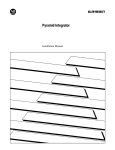
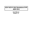
The 9914V is a 9-Track Tape Unit packaged in a vertical format, featuring quad density
and suitable for mounting in a shallow 19-inch rack. It is a derivative of the well-proven
and highly-regarded 9914 tape unit, with its GCR capability and optional buffered
interfaces.
The 9914V has an easy-loading tape system which will accept reel sizes from 6 to 10.5
inches diameter. The tape is visible through the loading door at the front of the 9914V so
that the operator can verify tape tension and tape motion. Routine cleaning is facilitated by
opening the loading door to gain access to the tape path components.
The optional interfaces are SCSI, Super SCSI, or buffered Pertec Cache, their connections
to the host computer are made at the rear of the 9914V.
1.1 9914V Features
•
•
•
•
•
•
42 ips and 125 ips streaming, interface selectable
Up to 270 MByte unformatted data capacity
All four IBM compatible tape data formats to ANSI/ECMA specifications
Integral unit (no external boxes for any data format or interface)
B-character alphanumeric display for easy operator interpretation
Three levels of micro-diagnostics; power-on, operator, and host;
host diagnostics via either Pertec or either SCSI interface
• Aut~-threading, actuated by door closure or from the operator's panel
• Occupies less than 10 inches rack depth
FIGURE 1.1 9914V: GENERAL VIEW
CM 1088 (Draft Issue L)
Introduction
1-1
1.1.1
Short-Form Specification
Reels
10.5,8.5,7 or 6 inch on a standard IBM hub
(267, 216,178, or 152 mm)
Tape
Standard 12.7 mm (O.5 in) wide computer tape to
ANSI X3.40 or ECMA 62 specification.
(1.0 mil tape if extra data capacity is required)
Tape Tension
285 gm (10 oz) nominal
Format
IBM compatible to ECMA 62 or
ANSI X3.22 or ANSI X3.39 specification.
(there is no published ANSI or ECMA 3200 bpi specification)
Tape Speeds
Depends on the selected density, usually 42/125 ips:
Standard 9914 V
Low
High
800 NRZ
1600 PE
3200 PE
6250 GCR
42
42
62
42
Special Order
Low
High
125
125
62
125
50
50
50
50
100
100
50
100
All speeds are in inches per second (ips)
Weight (unpacked)
(approximate)
46 kg (101 Ib)
Supply Requirements
100, 120, 220 or 240 V ac, +10 -150/0, 48-62 Hz
190 VA working
40-56 V dc: 3.4 A average current @ 48 V
Dimensions:
Behind face:
Height
Width
Depth
589 mm
426 mm
245 mm
(23.2 in)
(16.8 in)
( 9.6 in)
Overall:
Height
Width
Depth
609 mm
482 mm
330 mm
(24.0 in)
(19.0 in)
(13.0 in)
Note:
Screened cable connectors increase the depth dimension,
by the connector depth and the cable bending radius.
Temperature
Operating + 10 to +40 °C
Other parameters
Set out in the 9914V Product Specification
1-2
9914V User I Diagnostic Manual
eM 1088 (Draft Issue L)
1.2 Tape Speeds
At most densities, one of two tape speeds may be seleeted according to the application:
(a) the low speed (where the tape can be rapidly repositioned between data blocks) for
situations where the host cannot sustain data transfer at high rates;
(b) the high speed (where data is normally transferred on-the-fly) where the host can sustain
fast transfers and thereby achieve a high average data rate.
1.2.1
Data Rates
When a block is being transferred to tape, each byte is accepted by the 9914 V at a rate
determined by the tape speed, recording density (GeR, PE or NRZ)i and interface
(unbuffered Pertee, SCSI or buffered Pertee). At 800, 1600, and 6250 bpi, the user may
select from two streaming speeds. The inter-relationship of tape speed and synchronous
data rate for the unbuffered Pertec interface is detailed in Table 1.1. Where the SCSI or
Pertec Cache board is fitted, the burst rate may be higher.
Density
(bpi)
Speed
NRZ
800
La
Hi
PE
OPE
1600
3200
La Hi
La La
GCR
6250
La
Hi
Data rates (kB/s):
421125 ips
33.3 100
66.6 200
50/100 ips
40
80
80
160
200
200
260
781
80
80
312
625
Note: 42 ips is actually 41.66 ips; 62 ips is actually 62.5 ips
TABLE 1.2 9914V DATA RATES
1.3 Tape Loading
In order to load tape into the 9914V, the operator has to open the loading door and push
the tape reel on the self-centring hub in the loading chamber; the pushing action both
locates the reel and locks it onto the hub. The auto-threading procedure is usually initiated
when the loading door is closed; the tape is then threaded, tensioned, and advanced to
BOT (which is indicated on the display).
The user may (via configuration option 04) actuate threading from the operator's panel
, LDIONL ' button in preference to auto thread-on-closure, Section 2 details this option.
This loading system makes for simple, speedy and reliable tape threading, without the
operator touching the tape surfaces and with the milestones indicated on the operator's
display.
For operator safety, the 9914V is interlocked so that its loading door must be shut before
loading can commence or tape motion be initiated.
CM 1088 (Draft Issue J)
Introduction
1-3
No take-up spool need be fitted, since this is built into the 9914V and should only be
removed by service personnel.
Tape loading is described in more detail in Section 3.
1.4 Operator Controls and Indicators
The operator controls, the 8-character display, and the backlit legends are located at the
front of the 9914V on the right-hand side. In diagnostic mode, the controls adopt
secondary functions as printed on each button membrane.
In general the alphanumeric display gives temporary intemal status, activity, or diagnostic
information while the backlit legends inform of permanent status such as Write Enable.
All controls and indicators are described in detail in Section 3.
1.5 Diagnostics
When power is applied to the 9914 V, the self-test diagnostics are automatically invoked to
check basic internal functions which would otherwise inhibit normal use of the 9914V.
The operator may use diagnostiC mode to run a range of internal diagnostic programs
which are suitable for assurance of machine integrity, and for firsHine diagnosis of faults.
These programs may be selected from a program suite to include full data tests with or
without tape motion. Diagnostic programs can be run individually, grouped together or
looped. Special Status Byte registers are allocated for error logging, status, and diagnostic
information; the operator may display these bytes using the front panel controls.
The host computer may also call diagnostic programs (individually, stacked, or looped) by
special commands across the interface. Diagnostic results are available to the host
computer by using Request Status type commands to acquire status bytes via the interface
Read Data lines. The status bytes are tabulated in Section 4 and described in detail in the
9914V Product Specification.
The diagnostic programs and error messages are described in Section 4; an overview of
the available features is set out below:
• Power-on health check
• Front panel or host operation
• 8-character alpha-numeric display of status and fault code
• Simple dual operation of control buttons
• Run/pass/fail indication
• Dedicated program stack, tailored stack, or program looping
• Error logging facility - report on request by host computer
1.6 Interfaces
The 9914 V may operate with one of several interfaces.
1.6.1
Industry Standard
The unbuffered Enhanced Pertee interface is implemented by factory-fitting a printed edge
connector board (with the industry-compatible two-connector layout) at the rear of the
9914V.
1-4
9914V User I DiagnostiC Manual
eM 10sa (Draft Issue H)
The Pertee interface supports encoded inputs for various commands, the unallocated
combinations are used by the Company to provide additional commands for such purposes
as controlling the resident diagnostic programs, or accessing status byte data; the
command set and pin connections are both set out in Section 6. This feature gives the
user improved control without requiring extra interface lines.
1.6.2
SCSI
The SCSI interface option is implemented using a single printed circuit board, fitted within
the 9914. The SCSI interface bus is connected via a shielded socket (at the rear of the
9914). Both single-ended and differential variants are available.
1.6.3
Pertec Cache
The buffered cache option is implemented using a single printed circuit board, fitted within
the 9914. Buffered Pertec interface signals are made via a screened connector box (at the
rear of the 9914).
1.6.4
Super SCSI
The Super SCSI interface option is implemented using a single printed circuit board, within
the 9914. The SCSI interface bus is connected via a shielded socket (at the rear of the
9914). Single-ended, differential, and dual variants are available.
1.7 Technical Description
The 9914V is constructed around an aluminium alloy deck casting which is machined to
accommodate the mechanical sub-assemblies, and hinged to a box-section enclosure
which also carries the electronic sub-assemblies.
Access to the tape path area for routine cleaning is by way of a hinged loading door,
revealing the entire tape path when opened.
The 9914V has a short tape path using one tension arm which returns to a rest position in
the absence of tape tension to simpiiiy the tape iacing path. The unique suppiy hub design
enables the tape reel to be located squarely and clamped firmly by a simply pushing
action. When the self-threading procedure has been initiated, the tape is threaded by air
pressure through the tape path, taken up on the take-up reel, tenSioned, and moved
forward until BOT is reached, without any further operator involvement. The fixed take-up
spool is of special Company design to enable this loading procedure.
To gain access to the tape path, personnel may pull the loading door handle to open the
loading door and expose the entire tape path.
For access to the data electronic assemblies and the rear of the deck casting, the 9914V
casting may be hinged forward. The card cage may then be hinged forward to gain access
to the data boards. It is not envisaged that there will be any circumstances when it will be
required to demount the 9914 V from the rack.
CM 1088 (Draft Issue H)
Introduction
1-5
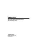
1.8 Reposition Cycles
The 9914V employs long starts and stops while still recording tape with normal inter block
gaps (IBG). The microprocessor controlled servos, together with the tacho (which is driven
by the contact of the tape around its roller) and tape position encoder, accurately reposition
the tape, allowing relatively long stop and start distances to be used with space-back
routines. Following a 'stop', a space-back reposition sequence is implemented, to a point
where the tape can achieve streaming speed before the next block. (see Figure 1.8)
~~____B_LO_C_K________~i_NT_E_R_-_B_L_OC_K__G_A_P~___B_L_O_C_K__~~
---~)
A
(
COMMAND
RE-INSTRUCT
TIME
t--
B
FIRST
DATA BYTE
H
G
•
o
FIGURE 1.8 SIMPLIFIED REPOSITION CYCLE
1.9 Data Capacity
Table 1.9 (a) shows lengths of tape normally supplied on standard tape reels.
Reel diameter
(inches)
6.0
7.0
8.5
10.5
1.5 mil
Tape length (feet)
1.0 mil
400
600
1200
2400
600
900
1800
3600
TABLE 1.9 (a) TAPE LENGTHS
1-6
9914V User I Diagnostic Manual
CM 1088 (Draft Issue H)
Table 1.9 (b) shows unformatted data capacities and illustrates the variation of formatted
capacity (in Mbytes) with block size, assuming an IBG of 0.6 inch at 800 through 3200 bpi
and 0.4 inch at 6250 bpi.
Density
(bpi)
Tape length
(feet)
Unformatted
capacity
lK
Formatted capacity
8K
64K
800
800
800
600
2400
3600
5.7
23
34
3.9
15
23
5.4
21
32
5.7
23
34
1600
1600
1600
600
2400
3600
11
46
69
5.7
22
34
10
40
61
11
45
68
3200
3200
600
2400
7.8
31
3200
3600
23
92
138
46
18
74
111
22
89
134
6250
6250
6250
600
2400
3600
45
180
270
12
50
75
33
135
203
43
172
258
TABLE 1.9 (b) 9914V DATA CAPACITIES (Mbytes)
1.10 Associated Documentation
The following M4 Data documents provide additional information relating to the 9914 V.
124654
9914V Product Specification
123489
9914V 9-Track Tape Unit Servicing Manual
(eM 1089)
~
121780
SCSI User Manual
121789
Pertec Cache Interface Product Description
124658
Super SCSI User Manual
The following STK documents provide additional information relating to the 9914V.
M G8015-A
9914V Product Specification
95124766 xx
9914V 9-Track Tape Unit Servicing Manual
95 121798 xx
9914 SCSI User Manual
95 121799 xx
9914 Pertee Cache Interface Product Description
95124767 xx
9914 Enhanced SCSI User Manual
CM 1088 (Draft Issue L)
Introduction
1-7
The following documents provide background information on data recording.
ANSI X3.22 (1983)
Recorded magnetic tape for information interchange
(800 CPI NRZ).
ANSI X3.39 (1986)
Recorded magnetic tape for information interchange
(1600 CPI PEl.
ANSI X3.40 (1983)
Unrecorded magnetic tape for information interchange
(9-track 800 bpi NAZ, 1600 bpi PE & 6250 bpi GCR).
ANSI X3.54 (1986)
Recorded magnetic tape for information interchange (6250 bpi
GCR).
ANSI X3.131-1986
Small Computer Systems Interface.
ANSI S12.10-1985
Methods for the Measurement and Designation of Noise Emitted
by Computer and Business Equipment.
ECMA 62
Data interchange on 12.7 mm (0.5 inch) 9-track magnetic tape.
(NRZ, PE & GCR).
The following documents are published requirements for RFllimits.
VDE 0871
Radio interference suppression of radio frequency equipment for
industrial and medical (ISM) and similar purposes.
CFR Rules 47-15J
Code of Federal Regulations.
15J = RFI requirements for computing devices.
1-8
9914V User I Diagnostic Manual
CM 1088 (Draft Issue H)
2.
Installation and Checkout
This section outlines the contents of the 9914V crate, describes how to wire the mains
lead, how to mount the unit in a rack, the operator options, and how to check out the unit.
2.1 Uncrating and Inspection
2.1.1
Uncrating the 9914V
The 9914V is packed in special impact-absorbing materials which are placed inside a
heavy-duty cardboard box.
Any unpacking instructions are enclosed in a polythene envelope attached to the upper
face of the cardboard box. Note: do not lay the unpacked 9914 V on it's back.
Packed dimensions:
millimetres
inches
380 H x 605 W x 800 D
15.0 x 23.8 x 31.5
Packed weight:
54 kg (119Ib).
(approximate)
2.1.2
Inspection
The packing box should contain the 9914 V itself and associated items such as:
- an ac mains supply lead with a moulded IEC socket, (not with dc-powered machines);
- manual(s) as specified with the order:
a 9914V User/Diagnostic Manual, andlor9914V Servicing Manual,
a 9914 SCSI (or Super SCSI) User Manual, ora 9914 Pertec Cache Product Description;
- rack-mounting accessories;
- other hardware, if specified on the order.
After the 9914V has been uncrated it should be visually checked for any damage that may
have occurred during transit.
All items should be checked off against the requirements of the order.
2.2 Preparing for Mains Supply Connection
The sections up to 2.2.5 include the checks which should be made before an ac-powered
9914V is connected to a mains supply. Connection to a de supply is described in Section
2.2.6.
2.2.1
Supply Suitability Checks
1. The ac-powered 9914V must be connected to a nearby mains socket outlet (or a doublepole switch with contact gaps in excess of 3 mm) as part of it's installation. This is
necessary because the 9914V mains switch does not isolate both mains connections.
2. The 9914V should be checked for supply setting, which is printed on a label at the rear of
the machine. The actual setting, which is visible on the mains input socket (see Figure
2.2.2) must match this, otherwise the setting must be changed and the fuse rating
checked.
CM 1088 (Draft Issue L)
Installation and Checkout
2 -1
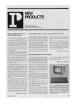
2.2.2
Supply Voltage Resetting
Follow this procedure only if the input voltage selection setting is incompatible with the site
supply voltage; otherwise go to ' Wiring the Supply Plug'. Four ac settings are possible,
100/120 V or 220/240 V, the input frequency may be between 48 and 62 Hz.
Note: when it is proposed to use the 9914 V on the 120 V setting, but the supply is known
to be consistently below 110 V, the input voltage setting should be changed to 100 V.
a) Changing the Voltage Setting
i) disconnect the supply lead from the input socket;
ii) insert a 5 mm flat-bladed screwdriver where illustrated (in Figure 2.2.2) and hinge the
panel open;
iii) withdraw the barrel-shaped voltage selector mechanism and re-insert with the new voltage
facing outwards, do not attempt to rotate the selector barrel in-situ;
iv) withdraw the fuse holder and install the new fuse (referring to (b) below to ensure the
correct rating).
b) Supply Fuse Rating (Littelfuse type 313 is suitable)
- For 100/120 V settings, FS 1 is a 1.25", 4 A, slow-blow;
- For 220/240 V settings, FS1 is a 1.25", 2 A, slow-blow.
~
SCRE~DRIVER
l=J~r-SLOT
I ....... l
VOLTAGE
RANGE
/
1240Vacl
....
(
......
[!]
[IJ
FUSE
CARRIER
®
[!]
FIGURE 2.2.2 VOLTAGE SETTING
2-2
9914V User 1 Diagnostic Manual
eM 1088 (Draft Issue H)
2.2.3
Wiring the Supply Plug
Warning - the 9914V must be earthed
The moulded IEC socket on the supply lead fits a chassis-mounted plug located at the rear
of the 9914V. When the other end of the supply lead is unterminated, a suitable plug must
be attached.
As the colours of the cores in the 9914V mains lead may not correspond with the coloured
markings identifying the terminals in your plug, the following sections relate core colour to
pin identification.
2.2.4
Outside the USA
Connect the cores as tabulated in Table 2.2.4.
Core which is coloured:
Must be connected to the terminal
in the plug which is:
green and yellow
marked with the letter E, or
coloured green and yellow, or
marked with the earth symbol
(
I
)
-
blue
marked with the letter N, or
coloured black
brown
marked with the letter L, or
coloured red
Table 2.2.4 PLUG WIRING - OUTSIDE THE USA
Note: 2-pin plugs are not suitable. The earth wire must be ' grounded' for safety reasons.
The following translations of pin functions and colours is given.
English
Francais
Deutsch
LIVE (brown)
LlGNE (Brun)
POSITIV (Braun)
NEUTRAL (Blue)
NEUTRE (Bleu)
NEGATIV (Blau)
EARTH (GreenlYellow)
TERRE (VertlJaune)
ERDE (Gelb/GrOn)
2.2.5
Within the USA
Connect the cores as tabulated in Table 2.2.5.
CM 1088 (Draft Issue H)
Installation and Checkout
2-3
Core which is coloured:
Must be connected to the terminal
in the plug which is:
green and yellow, or
green (US-style lead)
half-round gold (ie the earth)
blue, or
white (US-style lead)
flat silver (ie the neutral)
brown, or
black (US-style lead)
flat gold (ie the live)
Table 2.2.5 PLUG WIRING - WITHIN THE USA
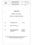
2.2.6
DC Supply Connections
The customer is required to provide his own connection leads from his supply source to the
9914V.
Connections are made to the rear of the 9914V, to spade connectors. There are two male
6.3 mm spade contacts (identified II - II and II + ") and an adjacent 8-32 insert which takes
the 8-32 screw supplied with the 9914V. Figure 2.2.6 shows a close-up view of the
connectors.
Connecting wire should have a minimum rating of 10 A dc continuous, it is recommended
that the cable length be kept to a minimum to reduce voltage drops. If crimp connections
are used, care should be taken to ensure that the wire diameter, insulation thickness,
terminator and crimp tool are all compatible.
It is suggested that the ground connection is made using an 8-32 or M4-size ring tag and it
is recommended that the shakeproof washers supplied be fitted one on either side of the
ring tag.
When the connections have been made, it is recommended that the cables be secured by
means of the cable tie which is fitted to the rear of the unit for strain relief.
Negative
Positive
DC Power Leads
6.3 nn
Spade Connectors
(supplied by the custoner)
'OJ
8-32
Ground
Insert/
Figure 2.2.6 DC POWER CONNECTIONS
2-4
9914V User I Diagnostic Manual
CM 1088 (Draft Issue K)
2.2.7
DC Input Power Safety
In order to meet the safety requirements of BS 7002 (or EN 60950) for a class 1 machine,
a safety earth must be fitted to the terminal marked with the "fir tree" sign (shown in Table
2.2.4 and defined in No. 5019a of IEC Publication 417).
The dc power input hardware has been designed so that (when the connecting cable ends
are fitted with compatible insulating boots and pushed fully home when installed) the
installer cannot touch non-ELV parts of the power system.
Where the dc 9914V is run from a mains-derived supply, the installer must ensure that the
de supply conforms to the isolation requirements on the caution label near the power input
connectors.
2.3 Rack Mounting
The 9914V may be fitted by several methods.
a) In a standard 19-inch EIA rack, using it's customer-specified rack clamps. Warning: the
customer must provide a base tray which supports the weight of the 9914V.
b) In a standard 19-inch EIA rack, using fixing screws which are inserted from the rear of the
front opening and engage with tapped holes in the 9914V's mounting frame.
c) In a wider-than-standard rack, using fixing screws which are inserted from the rear of the
customer's mounting frame and engage with tapped holes in the 9914 V's mounting frame.
Fitting Precautions
It is advisable to ensure that the equipment rack has either a low centre of gravity with the
9914 V installed or, alternatively, has forward protruding feet. This precaution is necessary
to reduce the possibility of toppling when the 9914V is hinged out.
It is recommended that the rack be adequately ventilated and that a ventilation panel be
fitted at the top. Warm air emerges from the louvres at the top of the 9914V.
Note: do not lay the unpacked 9914 V on it's back.
2.3.1
Fitting Sequence, USing Rack Clamps
Warning
Fit a base tray before starting this procedure
Figure 2.3.1.1 shows a rear view of the 9914V and illustrates where the rack clamps are
located.
i) Check that a base tray is securely fitted and is substantial enough to support the 9914V's
weight. Warning: the tray must both locate the 9914V while the rack clamps are engaged
and subsequently keep the unit in place if the rack is moved.
ii) Check that the mains supply lead is disconnected.
iii) Ensure that the rack clamps are set in the vertical position (ie parallel to the sides of the
rack, as shown in Figure 2.3.1.2).
Note: an Allen Key is supplied with the 9914V.
CM 1088 (Draft Issue L)
Installation and Checkout
2-5
I
~<--------------------TY-P-I-C-A-L_R-A-C-K-O-P-E_N-I-NG--~-I-D_TH
_____________________~I
450 nn
17.72 In
........--....-
CLAMP
IE
SCRE~
439.2 nn
CENTRES
~I
17.29 In
~
g
•
•
AC POWER INPUT
/
0
~I:
RACK
CLAMPS (4 )
DC POWER INPUT
•
!O
a>
0
I/"l
a>
-
•
1
c
C
N
0
N
DIFFERENTIt\L
:
\
\
...
7
7
SINGLE ENDED
SCSI
\
:
7
7
\
....
.
-
RACK FRAME
.....
~
E
9914V
BEHIND-RACK
426 nn
~IDTH
BASE
TRAY
/
::>
16.77 In
~
Figure 2.3.1.1 9914V RACK CLAMP LOCATIONS
2-6
9914V User I Diagnostic Manual
CM 1088 (Draft Issue L)
c
In
a>
r-.
•• "v
(
I
(~~~SED
CLAMP
(
RELEASED
><
RACK FRAME
E~<~~FR'ME
I,~
(0
~
\
)
9914V ENCLOSURE
Figure 2.3.1.2 9914V RACK CLAMP DETAIL
Warning
The 9914V should not be lifted by one person
iv) With a second person, lift the 9914V and keeping it vertical, place it on the base tray and
fully into the rack.
Note: steps (v) to (ix) must be executed in sequence.
v) Open the loading door. Undo the screw securing the deck casting to the base frame (this
is located in the top right hand comer). Close the loading door securely.
vi) Check that the loading door is fully closed. Note whether the clamps are free to rotate and
engage the rack frame.
vii) With a second person to push against the 9914V's mounting frame, pull down the deck
casting.
If the rack clamps did not have sufficient clearance at step (vi), rotate them anticlockwise
until there is sufficient clearance and then align the clamps to the' released' positions of
Figure 2.3.1.2.
If the rack clamps did have sufficient clearance at step (vi), insert the 5 mm AlF Allen key
into each topmost clamp screw (annotated' 1 ' in Figure 2.3.1.3) and rotate continuously
clockwise until tight. Do not rotate anticlockwise because this may mis-align the clamp.
CM 1088 (Draft Issue K)
Installation and Checkout
2-7
~l
Figure 2.3.1.3 9914V RACK CLAMP ACCESS
viii) Use the same Allen key to tighten each clamp screw (annotated' 2 ' in Figure 2.3.1.3) by
rotating continuously clockwise until tight. Do not rotate anticlockwise because this may
mis-align the clamp.
Close the deck casting.
ix) Check that all four rack clamps have rotated to the' holding' positions of Figure 2.3.1.2. If
not, repeat the steps from (vi) onwards.
x) Open the loading door and tighten the screw securing the deck casting to the base frame.
Close the loading door.
Note that the fitting procedure involved a total of four rack clamps.
2-8
9914V User / Diagnostic Manual
CM 1088 (Draft Issue L)
2.3.2
Fitting Sequence, Using Fixing Screws
Figure 2.3.2.1 shows a rear view of the 9914V and illustrates where the fixing screws are
located.
i) If a base tray has been fitted, check it is securely fitted and is substantial enough to
support the 9914 V's weight.
ii) Check that the mains supply lead is disconnected.
Warning
The 9914V should not be lifted by one person
iii) Check there is access to the rear of the front rack members, in order to fit the fixing screws
later. The sides of some racks are detachable.
iv) Check there are 6 fixing screws, 1/4 UNC, with a minimum thread depth of 19 mm (3/4 in)
available.
v) With a second person, lift the 9914 V and keeping it vertical, place it in the rack at its
intended height.
vi) Fit the top two fixing screws, hand tight.
vii) Fit the other four fixing screws, hand tight.
viii) Tighten aU six fixing screws fully.
ix) Pull down the deck casting. Check that it hinges without obstruction.
2.3.3
Fitting Sequence, Using Customised Mounting Frame
Where a customised mounting frame is used, the customer must use a compatible
procedure which takes account of the design of the frame.
The general principles of undertaking only two-man lifts and ensuring any base tray is
substantial still apply.
CM 1088 (Draft Issue L)
Installation and Checkout
2-9
MOUNTING SPAN
465 nn
16.31
In
....I - - - - - - - - - - - - - - - - - - - - - - - - - - - - - - - - - - - - - - - - - - - - - - - - - t
AC PO'w'ER INPUT
:.
..
o
DC POWER INPUT
..
..
RACK
/
MOUNTING
POiNTS (6)
TAPPED
1/4
UNC
:.
.:
DIFFERENTIAL
SINGLE-ENDED
SCSI
\
....~==========================================__t ....
~ IE(_____________________4_2_6_n_n____16_._7_7__ln____________________-7)1 ~
Figure 2.3.2.1
2 -10
9914V RACK SCREW LOCATIONS
9914V User I Diagnostic Manual
CM 1088 (Draft Issue L)
I
2.4 Configuration, Link and Switch Options
2.4.1
Termination Power
A link is provided on the Data Control board to allow for the position of the 9914 V in a
daisy-chain configuration. The link settings are:
Link Position
Termination Power source
Away from board edge (int)
Near board edge (ext)
internal +5V
external +5V
Any other links on the Control board are set during manufacture and should only be altered
by trained service personnel.
2.4.2
Operator Functions
Most operator control options are held in non-volatile RAM, which can be examined or
altered by running diagnostic program 67. This section describes how to alter options
which do not affect the operation of the host software or the format of data written to the
tape.
2.4.2.1
Displaying/Modifying Options
Run diagnostic program 67, using the following procedure.
Check that the 9914V is not exchanging data with the host, take the 9914V off-line. Press
the DIAG button to bring up the I Test 00 I display, use the I tens I and I units I buttons until
the display reads I Test 67 '. Press I run/stop I, the display indicates as follows at the
various steps.
OPT 01
Indicated upon first entering diagnostic program 67, the desired option
number (which is flashing) can now be changed by depressing the
I units I button.
OPT 05
When the desired option is displayed, press DIAG.
UNIT 01
Indicated after the desired option has been selected, and DIAG has been
pressed. This is the current setting of option 05.
If option 05 is to be altered, use the I tens I and I units I buttons to display
its new setting, otherwise proceed to the next step.
UNIT 02
When the required option setting is displayed, press DIAG to revert to
displaying option numbers.
OPT 02
If no further options are to be changed, press I run/stop I to exit
diagnostic program 67, otherwise repeat the procedure for other
option(s).
CM 1088 (Draft Issue K)
Installation and Checkout
2 - 11
2.4.2.2
Operator Options
The displays associated with the operator options are tabulated next.
Config Byte 01 Duration of density display
DNSDIS-1
DNSDIS-O
Density displayed until' run/stop' or' tens' pressed
Density displayed for 5 seconds only.
Config Byte 02 This option has no function on the 9914 V model.
Config Byte 03 Auto on-line
Aut Open
Man Open
9914 V automatically goes on-line after threading has completed.
9914V is on-line only after' LD/ONL ' is pressed.
Config Byte 04 Auto load
AutoLoad
Man Load
9914 V automatically threads tape to BOT on closing the door.
9914V threads tape when' LD/ONL' button is pressed.
Config Byte 05 Unit address
Unit XX
Where XX is the current unit address (valid in the range 0 to 7).
Warning: there are configuration bytes numbered beyond 05, but these may re-configure
the 9914V so as to alter its response to the host or change the format of recorded data.
Configuration bytes 06 to 17 should only be changed by personnel who are fully
conversant with the system, these engineer options are listed under diagnostic program 67
in Section 4, and tabulated in Appendix A.
2.4.3
Analogue Data Paths Board
There are no switch or link option settings on this board.
2.4.4
Digital Data Paths Board
There are no switch or link option settings on this board.
(The potentiometers are set during manufacture, they must not be subsequently adjusted
in the field).
2.4.5
Optional Interface Boards
When an optional interface board is fitted, the user should refer to the appropriate manual:
SCSI Interface
User Manual 121780
Pertec Cache Interface
Product Description 121789
Super SCSI Interface
User Manual 124658
2 -12
9914V User / Diagnostic Manual
CM 1088 (Draft Issue K)
2.5 Initial Checkout
The user who is not already familiar with the 9914V controls and indicators is advised at
this point to read Section 3 to gain some familiarity with the 9914V's operations.
To prove the 9914V's integrity:
i) Check that the 9914V's supply voltage selection is correct (see Section 2.2.1).
ii) Remove any protective packaging from the read/write heads.
iii) Check that the 9914V is switched off, connect the supply lead to the input socket.
IV) Switch on the 9914V, after several seconds the display panel indication should be
, TESTING', then' LOCATING', and finally' NO TAPE', otherwise see Section 3 for fault
messages.
Warning: the 9914V mains switch does not isolate both mains connections (a
warning to this effect follows, in German):
Die Trennung vom Netz erfolgt durch Zeichen des Netzsteckerl
(ISolation from the mains is only guaranteed by removing the mains plug).
v) Load a scratch tape; read' Loading and Unloading' in Section 3 if this procedure is
unfamiliar.
vi) Run diagnostic program 01; this is a check of machine integrity, including writing data to
the tape.
vii) When diagnostic program 01 has passed, the 9914V is ready for on-line use.
2.6 Final Checkout
Caution: the 9914V is designed to meet several RFI requirements, for industrial use. If
operated in a residential environment, it has a high potential for causing interference. The
user must correct this, by the use of screened interface cables and/or rack mounting.
When the 9914V is fitted with a buffered interface, and the interface bus cable is not
completely enclosed within a cabinet where precautions are taken to limit radiated
emiSSion, shielded connectors and cables should be used. A suitable SCSI connector (3M
socket type 3565-2002 or Sun-style type 8350-8005) may already be fitted to the 9914V.
i) Set power off.
ii) Connect the interface cables, the SCSI interface connections are shown in Figure 2.6.
iii) Set power on, re-Ioad the tape, and run the host diagnostic or commissioning program to
prove the complete system.
iv) Remove any protective peel-off sheet which is attached to the tape path cover.
CM 1088 (Draft Issue L)
Installation and Checkout
2 -13
AC PO\JER INPUT
:0
o
0"
DC PO\JER INPUT
:0
.0:
:0
0:
DIFFERENTIAL
\---------'
SINGLE-ENDED
SCSI
\'---~
\
Figure 2.6 CONNECTOR LOCATIONS, SCSI INTERFACES
2 -14
9914V User / Diagnostic Manual
CM 1088 (Draft Issue L)
3.
Operation
This section describes the functions of the operator-accessible controls and indicators.
3.1 Operator Functions
The operator is able to perform any of the following functions:
• Switch the 9914V power on or off at the front panel.
• Select the recording density.
• Check and for change any operator options.
• Mount a tape reel, and thread the tape.
• Call diagnostic mode in order to
run diagnostic programs: Dr
identify the servo, data, or SCSI firmware revisions, or
analyse the status bytes.
• Cancel diagnostic mode.
• Set the 9914Vonline, (the host then has control of the 9914V).
• Set the 9914V offline.
• Rewind the tape to BOT, and/or unthread the tape.
• Demount the tape reel.
3.2 Controls and Indicators
Figure 3.2 is a facsimile of the operator's panel.
ION L1NEI
IWTENI
6250 GCR
I DIAG I
I
EOT
I
LO/ONL
RWojUNL
RESET
DENSITY
tens
units
run/stop
enter
FIGURE 3.2 FRONT PANEL CONTROLS AND INDICATORS
CM 1088 (Draft Issue H)
Operation
3 -1
3.2.1
Controls
Power
on/off
This single-pole, two-position power switch is located at the front right
hand side of the 9914V and connects mains input power to the power
supply unit. When set to off, the power supply outputs are not active but
mains power is still present within the 9914V.
DIAG
Diagnostic mode is alternately set or cancelled by pressing this button. If
DIAG is not illuminated, press to set diagnostic mode; if DIAG is
illuminated and a program is not active, press to cancel diagnostic mode.
This function of the DIAG control is ineffective when the 9914V is online.
When certain diagnostic programs are active, DIAG is sometimes used
for special functions within the program.
LD/ONL
Press to initiate threading, or to set the 9914V online when threading has
completed.
Note: option 04 is normally set to automatically initiate threading when
the loading door is closed). Option 03 is normally set to automatically
place the 9914V online when threading has completed.
RWD/UNL
Press (when the 9914V is not online) to rewind the tape to BOT.
Press (when BOT is indicated) to unthread the tape (ie completely rewind
the tape onto the reel, prior to the operator unclamping it.
Note: if RESET is held pressed while RWOIUNL is momentarily
depressed, the subsequent rewind takes the tape beyond BOT and into
the unthreading sequence.
RESET
DENSITY
Use to set the 9914V offline and for cancelling threading or unthreading
sequences.
Normally used to select the required operating density or check the
current density setting (Section 3.7 gives precise operating details);
exceptionally used in specific instances for other functions.
tens
In diagnostic mode, ' tens' is used to select the tens digit of the program
number. Press and hold in order to increment the displayed program
number approximately every second. When the desired number is
displayed, release the button.
units
Used in a similar manner to the' tens " this button is used to select the
units digit of a diagnostiC program.
run/stop
Used to start or stop a program or program stack. When a program
number is displayed, pressing' run/stop' starts that program running;
when a program is running, pressing' run/stop' stops that program
running, pressing again usually either restarts the program from the
beginning, or (if running a stack of programs) starts the next program of
the stack.
If a firmware halt exists in a program, then the operator actions should be
obeyed, and' run/stop' pressed to continue.
3-2
9914V User / DiagnostiC Manual
eM 1088 (Draft Issue H)
enter
3.2.2
Normally used to enter a program number to a sequential list of
programs known as the program stack, exceptionally used in specific
instances for other functions.
Indicators
WT EN
WT EN is illuminated when a Write Enable ring has been detected on the
supply tape reel. The ring is sensed during the threading sequence and
WT EN is activated near the end of the sequence.
If the indicator is not illuminated after the threading sequence has
completed, the Write Enable ring was not detected. All subsequent
operator diagnostic programs involving writing, and all host Write
commands will be rejected.
ONLINE
When ONLINE is illuminated, the host is able to communicate with the
9914V. The 9914V may be set offline either by a host command, or by
depression of the RESET button.
DIAG
Diagnostic mode indicates that the 9914V is either running, or is ready to
run, diagnostic programs. This applies both under operator control and
under host control.
EOT
This is illuminated when the EOT marker is opposite the photo detector
in the tape path. Note that this differs from the EOT indication on the 8character display, where ' EOT ' denotes operation at or beyond the
marker.
EIGHT
CHAR'TER
DISPLAY
The alphanumeric display is always illuminated, after power-on, with
information such as BOT, READY, or REWIND. In some instances,
a scrolled message is dispiayed to convey more precise information than
is possible with an abbreviated message.
3.3 The a-Character Display
This section lists the messages which are placed in the 8-character display, they are
classified by operating mode or circumstance. The special and scrolled messages
associated with diagnostic mode are set out in Section 4.
Note: the display is illuminated at all times after power-on. If the £kharacter display is not
illuminated, and none of the status indicators are illuminated, check that the front panel
mains switch is set to I 1 I. If there are no displays with power on, this could indicate a
mains supply failure or a 9914 V fauff.
eM 1088 (Draft Issue H)
Operation
3-3
3.3.1
Power-up Indications
When power is applied to the 9914V, a series of power-up tests are run by the internal
diagnostics, with' TESTING' indicated. If a malfunction occurs, the display changes to
one of the following indications.
After a successful completion of the power-on tests, the display momentarily indicates OK
and then LOCATING; the operator may then mount a tape reel (as set out in Section 3.6)
and initiate the threading sequence.
Most fault indications which are preceded by' ** ' require the attention of an engineer, and
are therefore described in the 9914 V Servicing Manual.
blank display Mains power is not available, or
the +5 V supply is not present, or
the Servo Control bus is faulty.
CON VAL X (X in the range 1 to 7), usually a missing or disconnected sub-assembly.
OK
The power-up checks have been successfully completed.
POWER
TESTING
3.3.2
A fault has been found with the Power Supply board, while all the internal
dc power supply lines were being checked.
The power-up checks are in progress.
Diagnostic Indications
This section lists diagnostic indications which occur during operator initiated diagnostics,
online diagnostic messages are listed in Section 3.3.4.
DENS ERR
Selected density is not available (programs 82 & 83).
HALT XX
' run/stop' was pressed while a program was still running.
NO KEY
The called diagnostic program requires the service key code to be
entered before it can run; this applies to programs where the internal
configuration of the 9914V may be affected by running the program.
NO TEST
A non-existent diagnostic program has been called, or
the stack was empty when program 99 was called.
Offline
3-4
The tape is tensioned and forward of BOT with the 9914V not in
diagnostic mode, and not online.
9914V User I Diagnostic Manual
CM 1088 (Draft Issue H)
Pass 05
A diagnostic program (in this case, program 05) has passed.
Run 51
A diagnostic program (in this case, program 51) is running.
STK FULL
TEST 00
3.3.3
The diagnostic stack is fully loaded with 30 programs.
Diagnostic mode has just been entered.
General Indications
These indications c.ould occur during offline or online operation; messages which are
unique to a particular mode (eg threading) are described in other sections.
EOT
End-of-tape has been detected, the current working area is therefore at
or beyond the EOT marker.
IN LIMIT
The tension arm has reached the limit of its travel, tape tension has
usually been lost.
LID OPEN
Threading has been initiated, but the tape path cover thumb-screw
fasteners are not secured.
Offline
OK
The tape is tensioned and forward of BOT with the 9914V not in
diagnostic mode, and not online.
The 9914V does not have a fault condition.
ONLINE
The 9914V is online to the host, and able to respond to host commands.
READY
Tape has been threaded, and the 9914V is ready to accept host
commands.
REWIND
The tape is rewinding following either host or operator Rewind command,
this operation completes at BOT. If RESET is pressed during rewinding,
tape motion stops and the' REWIND' indication is replaced by' Offline '.
REW/UNLD An operator Rewind & Unload (ie Unthread) command has been given by
holding RESET depressed while RWD/UNL is depressed.
UNLOAD
An unload (ie unthreading) sequence is in progress following the
pressing of the RWD/UNL button while BOT was indicated. As the
unthreading sequence nears completion, the reel is unclamped and the
display briefly indicates OK before indicating READY (which is the
completion of unthreading).
>
Forward tape motion is in progress (usually displayed when a diagnostic
program is running).
<
Reverse tape motion is in progress (usually displayed when a diagnostic
program is running).
eM 1088 (Draft Issue H)
Operation
3-5
3.3.4
Online Indications
The following indications can occur when the 9914V is online but not running diagnostics.
Generally, the display remains until the next command is received.
Blank
A forward Read or Space interface command has been terminated after
9 m (30 ft) of blank tape (ie no data activity found).
Deselect
Unit online to interface, but not selected by host computer (ie deselected), and not at BOT.
Diag Stk
Diagnostic stack entry in progress.
Diag Oed
Dedicated diagnostic stack running (program 01).
EOTLIM
The tape has passed 3.6 metres (12 feet) beyond EDT and the 9914V
has been commanded to move tape further forwards.
Erase FL
An Erase Fixed Length command was accepted, at low speed.
Erase FL +
An Erase Fixed Length command was accepted, at high speed.
Erase VL
An Erase Variable Length command was accepted, at low speed.
Erase VL +
An Erase Variable Length command was accepted, at high speed.
Ex Sense
The extended (ie the full) status bytes were accessed.
** IDENT
No identifier (compatible with the selected density) found on leaving
BOT.
Ld Point
The tape is at BOT, and the 9914V is online (note, BOT is indicated
when offline in the same position).
Read
A Read command was accepted, at low speed.
Read +
A Read command was accepted, at high speed.
Read Only
A a write command has been given to a file protected tape (ie WT EN is
not illuminated). If writing is required, the operator must fit a Write
Enable ring to the tape reel.
READY
Reject
The 9914V is online to the interface but no commands have been
received. (Display shows' Ld Point' when at the BOT marker).
The last command received was rejected (for reasons other than file
protect), the reason is flagged in status byte F9.
, Reject' usually remains displayed until an acceptable command is
received; exceptionally (if BOT is found during a Reverse Read) BOT is
displayed. Placing the 9914V offline removes' Reject' from the display.
Rev Read
3-6
A Reverse Read command was accepted (with data transfer) at low
speed.
9914V User I Diagnostic Manual
eM 1088 (Draft Issue H)
Rev Read + A Reverse Read command was accepted (with data transfer) at high
speed.
Rewind
REWIUNLD
Tape is rewinding to BOT.
A Rewind & Unload (ie Unthread) command has been given; the
sequence rewinds tape to BOT and then continues until the tape is fully
on the supply reel, and the reel unclamped. The ONLINE legend then
extinguishes.
SecErase
An Security Erase command was accepted.
Sense
The condensed status bytes were accessed.
SpcFwd
A Space Forward command was accepted, at low speed.
SpcFwd +
A Space Forward command was accepted, at high speed.
SpcRev
A Space Reverse command was accepted, at low speed.
SpcRev +
A Space Reverse command was accepted, at high speed.
Srch Fig
A file search forward (ignoring data) command was accepted,
at low speed.
Srch Fig +
A file search forward (ignoring data) command was accepted,
at high speed.
Srch Fwd
A File Search Forward command was accepted, at low speed.
Srch Fwd +
A File Search Forward command was accepted, at high speed.
Srch Rev
A File Search Reverse command was accepted, at low speed.
Srch Rev +
A File Search Reverse command was accepted, at high speed.
Srch Rig
Srch Rig +
A File Search Reverse (ignoring data) command was accepted, at low
speed.
A File Search Reverse· (ignoring data) command was accepted,
at high speed.
STUCK!!
The tape appears to be stuck at the heads. Check the cleanliness of the
tape path. If clean, consider discarding that tape.
** Write
No write current was detected in the heads.
Write
A Write command was accepted, at low speed.
Write +
A Write command was accepted, at high speed.
Write FM
A Write File Mark command was accepted, at low speed.
Write FM +
A Write File Mark command was accepted, at high speed.
CM 1088 (Draft Issue H)
Operation
3-7
800 NRZ
800 bpi NRZ density.
1600 PE
1600 bpi PE density.
3200 OPE
3200 bpi (double PEl density.
6250 GCR
6250 bpi GCR density.
3.4 Automatic Self-Checks
3.4.1
Power-on Checks
When power is applied to the 9914 V, a self-check routine of the fundamental functions is
automatically initiated to detect failures which would otherwise inhibit its further use. The
error messages are set out in Section 3.3.1.
3.4.2
Other Automatic Checks
Continuous power-fail checks are made when 9914V is not selected, error messages are
as for power-on checks. Note that the host computer can request diagnostic tests when
data transfers are not in progress, in which case the DIAG legend illuminates while the
diagnostics are running.
3.5 Door Interlocks
The loading door operates a sensor when it is closed. The threading sequence cannot
commence until it is properly closed.
Caution: do not open the loading door after tape has been tensioned. If the 9914V is
online it will go offline; close the door and press LN/ONL to restore the online condition.
3.6 Threading and Unthreading
3.6.1
General
Before carrying out the following operating procedures, users should be familiar with the
care of tapes. Reels should not be handled by the flange and should always be placed in a
canister (or enclosed in a protective outer ring) when not in use.
Caution: once the tape has been tensioned, avoid opening the loading door. If the 9914V
is on-line, it changes to off-line; if tape is in motion, tape motion ceases. To restore the
status quo, the loading door must be securely closed and' LD/ONL must be pressed to
place the 9914V online.
I
3-8
9914V User I Diagnostic Manual
CM 1088 (Draft Issue J)
3.6.2
Power-on Procedure
To power on the 9914V, proceed as follows:
i) Set the power switch at the front of the 9914V to on (' 1 ').
• If there is no tape reel in the loading chamber, the display sequences as in Table 3.6.2.
• If there is a tape reel in the loading chamber, the display begins as in Table 3.6.2 but
proceeds from LOCATING to the LOADING stage of Table 3.6.3.
ii) Power-on fault indications are listed in Section 3.3.1.
Display
Status
Duration
TESTING
DIAG
Several seconds
Momentary
OK
LOCATING
ONLINE
NO TAPE
9914 V Activity
Power-on health check
Other indicators flash momentarily
Health check ok
Several seconds
Checking a tape reel is present,
supply hub rotates anti-clockwise
Momentary
Reel not detected on the SU hub
Tape reel may now be clamped,
see next section.
Scrolled
message*
* The message begins' To load tape press lDIONl .... '
TABLE 3.6.2 9914V POWER-ON SEQUENCE
3.6.3
Loading the Tape Reel
a) Power-on without a tape reel clamped
When there was no tape reel in the loading chamber, follow this procedure; otherwise
follow the instructions in (b) below.
i) Select a reel of tape.
ii) Ensure that the Write Enable ring is either fitted to permit writing, or removed to prevent
over-writing of existing data.
iii) Ensure the tape end is free; for new reels remove the adhesive strip and/or rubber block
which constrains the free end to the tape pack.
iv) At the end of the power-on sequence described in Section 3.6.2, the loading door may then
be opened to mount the tape reel on the supply hub. It is advisable to wait for the scrolled
message before mounting a tape reel, in case an internal fault prohibits further use.
v) Place the tape reel on the self-centering supply hub with the Write Enable ring towards the
casting.
CM 1088 (Draft Issue L)
Operation
3-9
vi) Close the loading door. Press' LDtONL '. Events should follow the sequence of Table
3.6.3 from' LOADING '.
Should tape loading malfunction, the possible display indications are listed in Section 3.6.4.
Display
Status
Duration
Scrolled
message
ON LI NE
Infinite
9914 V Activity
Waiting
Open the loading door
Mount a reel of tape on the SU hub
(Write Enable ring towards the casting)
Close the loading door
READY
LOCATING
Several seconds
Checking the reel is seated
LOADING
Several seconds
Threading and tensioning the tape
Several seconds
Determining the reel size,
XXX could be SML, MED, or LRG
Analyse
Several seconds
Density determination, result is
displayed for a few seconds
Ld Point
BOT
Infinite
Infinite
XXX REEL
(WT EN)
Tape is at BOT and 9914V is online, or
tape is at BOT and 9914V is offline
Notes to Table 3.6.3
• Ensure the tape reel is placed with the Write Enable ring nearer the casting.
• If DOOR is indicated, close the loading door securely.
• If the 9914 V is needed online at BOT, press LDtON L.
• Online status to the host is not set until BOT is reached.
TABLE 3.6.3 9914V TAPE LOADING PROCEDURE
b) Power-on with a tape reel inserted
If the 9914V has just been powered on with a tape reel, threading is automatic and follows
the sequence of Table 3.6.3 from' TESTING' onwards.
This feature is effective before or after BOT.
c) Substituting a Tape Reel
i) Remove the current reel of tape, by following the procedure described in Section 3.6.4.
ii) Mount the next reel, close the loading door, then watch the unit execute the procedure
from the READY indication of Table 3.6.3.
3 -10
9914V User t Diagnostic Manual
CM 1088 (Draft Issue J)
3.6.4
Unloading the Tape Reel
a) Removing the tape reel (with power on)
Note 1: if the unthreading sequence is commenced inadvertently it can be cancelled by first
pressing the RESET, then pressing LDIONL to resume threading (in order to resume, the
tape will probably move to BOT).
Note 2: for tape protection, place the reel of tape in a dust proof cover and store in a safe
place.
i) To avoid loss of data, check that the host computer is not accessing the 9914V. If the
dispaly shows' Offline', unloading may proceed without loss of data; but many of the
indications in Section 3.3.4 suggest that data transfer is still in progress. Tape motion also
suggests that data transfer is still in progress.
ii) Set the 9914V offline by pressing RESET, or (if in diagnostic mode) press the' DIAG '
control once to leave diagnostic mode (ie the DIAG legend not illuminated).
Note: if the 9914V does not go offline immediately RESET is pressed, it may be because
tile SCSI (or PCI) buffer contains panty processed data. That process will continue to
completion before the offline condition is aI/owed; do not assume the RESET button has a
fault.
iii) If' Offline' is displayed, hold RESET depressed while RWD/UNL is pressed, the tape
rewinds (with REW/UNLD indicated) through BOT until the tape is fully rewound onto the
supply reel (it is then ok to open the loading door).
iv) When the display indicates READY the loading door may be opened.
b) Removing the tape reel (during a power failure)
If power to the 9914V is cut off, and it is essential that the reel of tape is recovered without
waiting for power to be restored, the following procedure enables the user to do so. The
user should be aware that the time required to rewind the tape increases according to the
amount of tape on the take-up spool (ie the lower fixed reel).
i) Set power off. This is essential for safety reasons.
ii) Open the loading door, rotate the supply reel anti-clockwise until all the tape has been
rewound.
iii) Press the hub release button (ie the centre portion of the hub).
iv) Lift off the unclamped supply reel.
v) Close the loading door.
CM 1088 (Draft Issue J)
Operation
3 - 11
Threading I Unthreading Indications
3.6.5
These indications occur during threading and unthreading sequences plus some other
conditions when the 9914 V is under manual control.
Analyse
BOT
DOOR
HUB LOCK
The tape has reached BOT and the data circuits are reading the ident
burst to determine it's recorded density.
Tape is at BOT and threading is complete. When set online, the display
changes to ' Ld Point' and the 9914 V is able to respond to host
commands.
The loading door was open, after a threading sequence began.
Shortly after threading has been initiated, the reel has been clamped
onto the supply hub.
HUB ERR 1 Incorrect seating of the supply reel on the supply hub.
HUB ERR 2
HUB SOL
Incorrect seating of the supply reel on the supply hub.
The' located' flags are not changing, the hub lock solenoid may not
have locked the supply hub.
IN LIMIT
The tension arm has reached the limit of its travel, tape tension has been
lost.
LRG REEL
Near the end of the threading sequence, the firmware has detected that
a large (10.5 inch) reel has been used.
LOADING
Reel clamping has been confirmed, and tape is being threaded along the
tape path.
LOCATING
The positive location of the supply reel is being confirmed.
MED REEL
Near the end of the threading sequence, the firmware has detected that
a medium (8.5 inch) reel has been used.
NIC
Not In Chute; during the early stages of threading, tape was not detected
in the tape path chute (the tape end was attracted to the bulk, the foam
pad had not been removed, or the loading fan was not operational).
NO TAPE
NTU
OK
3 -12
After threading had been initiated, the reel locating circuits did not
conclude successfully, ie no tape reel was present on the supply hub.
No Take Up; during the later stages of threading, tape was not gripped
onto the take-up spool. No tacho pulses were detected.
The power-up checks have been successfully completed, or
the 9914 V is idle and does not have a fault condition.
9914V User I DiagnostiC Manual
CM 1088 (Draft Issue H)
REEL INV
RESET
During the early stages of threading, the tape reel was found to be
inserted with the Write Protect ring uppermost.
The RESET button was sensed as permanently depressed.
REWIND
The tape is rewinding following either host or operator rewind command,
this sequence completes at BOT. If RESET is pressed during rewinding,
tape motion stops and the REWIND indication is replaced by' Offline '.
REW/UNLD
An operator Rewind & Unload (ie Unthread) command has been given by
holding RESET depressed while RWD/UNL is depressed.
SML REEL
Near the end of the threading sequence, the firmware has detected that
a small (6 or 7 inch) reel has been used.
** TAB
The BOT tab was not detected, near the end of the threading sequence.
TAPE NOT
IN CHUTE
UNLOAD
3.6.6
Scrolled message. The tape end has not blown clear of the bulk,
An unthread sequence is in progress following the pressing of the
RWD/UNL button with BOT indicated. When the unthreading sequence
is complete the display changes to READY.
Threading the Tape by Hand
Since the 9914V is designed for fully automatic threading, it is not normally necessary (or
desirable) to manually thread the tape except under fault conditions such as a failed
loading fan.
i) Set power off. This is essential for safety reasons.
ii) Open the loading door, push the tape reel centrally onto the supply hub.
iii) Thread the tape through to the take-up hub.
iv) Wind on about two turns (an access hole is provided to facilitate take-up) until the tape is
pulled through when the tape-up reel is rotated.
v) Close the loading door.
vi) Set power on.
The threading firmware senses that tape is already threaded and proceeds to check for
clamping, tension the tape, and search for BOT without the operator taking any further
action. Threading indications and fault messages are set out in Section 3.6.4.
3.6.7
Switching off with Tape Threaded
It is good practice to ensure that the tape is unthreaded (or at least returned to BOT)
before switching off. The reel servo circuits are designed with a dynamic braking effect to
prevent tape loops forming following power failures or accidental switching off.
CM 1088 (Draft Issue H)
Operation
3 -13
3.7 9914V Problems
The operator's display indications are set out in Section 3.3. Read this section to
determine whether the 9914 V is suitable for further operation; if not, rewind the tape and
unclamp the reel.
In general, it is only necessary to switch off when some obvious hazard is present;
removing power from one 9914V in a daisy-chain configuration may disable the whole
configuration.
Possible causes of failure or loss of tape tension are
• mains supply interruption: when the power is restored, allow the tape to re-tension as
described in Section 3.6.3(b);
• servo fault; the tape traverses to one end (or remains motionless), regardless of any host
command or the RESET button;
• tape running off at EaT; caused by either a fault in the controller or program, or failure of
the EaT detection circuits;
• failure to see BOT reflective marker;
9914V fault, marker absent, or marker too far down the tape.
3.8 Density Selection / Interrogation
When the recording density option is set to enable operator selection (as opposed to host
selection), the density can sometimes be interrogated and! or changed via the DENSITY
button, with the current density setting indicated on the 8-character display. The selection!
interrogation methods and rules are described next
a) After power-on checks.
When the power-on checks have finished, the density defaults to the setting in the option
bytes and is not displayed. Should the density button be pressed, the display does not
indicate density because it is not relevant until a tape reel is present (ie no read or write
operation can take place).
b) Immediately After Threading
When the Analyse function has been enabled (byte 06, bit 2), it determines the tape
density at the end of the threading sequence (the tape can be seen moving to and fro, and
, Analyse' is displayed). 6250 or 1600 bpi ident bursts cause selection of the
corresponding density, no ident defaults to the option byte setting, blank tape or an alien
format defaults to the power-up default setting.
Manual density selection when threaded, at BOT, and offline, consists of depressing the
DENSITY button to cause the display to cycle continuously through the available densities.
Whichever density is displayed when DENSITY is released becomes the new recording
density during the next online command.
c) Online
The density setting cannot be updated from the front panel when the 9914 V is online, but
can be checked at any time by preSSing the DENSITY button. The current setting is shown
for a short time before the display reverts to its previous indication.
3 -14
9914V User! Diagnostic Manual
eM 1088 (Draft Issue L)
d) During Diagnostic Mode
Density selection in diagnostics is special because four programs are allocated specifically
for this purpose. Diagnostic programs operate in conjunction with the Data Control
firmware for density selection, thus if the 9914V was set to 1600 bpi before diagnostic
mode was entered, and altered to 6250 bpi during diagnostics, it will remain at 6250 bpi on
leaving diagnostic mode.
When running diagnostic programs, it is recommended that the density is specifically set
(by programs 41-44), rather than relying on a previous setting. If a program fails and an
error of the form ' F29 ErO 1 ' is displayed, the current density may be displayed by pressing
, enter '. To continue the program, it is then necessary to press DIAG to skip the error,
followed by , run/stop' to continue the program.
CM 1088 (Draft Issue H)
Operation
3 - 15
This page has no technical content
3 -16
9914V User I Diagnostic Manual
eM 1088 (Draft Issue H)
4.
Diagnostics
The 9914V's diagnostics offer a selection of programs (numbered 00 to 99), many of which
are useful to the operator and may be controlled from the operator's panel.
The pass and fail messages which are displayed for most diagnostic programs are given in
self-explanatory alphanumeric format.
During failure conditions, the brief error message usually contains the failed program
number and the error code. These messages assist service personnel in locating the
possible faulty Field Replacement Unit (FRU).
Some program descriptions make reference to interface signal names (eg ICER, IHER,
IFBY), these are defined in the 9914V Product Specification.
Note: because some diagnostic programs write data to tape, it is good practice to load a
scratc/. tape before invoking diagnostic mode.
4.1 Diagnostics - from the Operator's Panel
4.1.1
Operator Diagnostics
Most diagnostic programs may be controlled from the front panel, those which cannot are
host-specific functions.
The operator may use the diagnostics:
• to confirm primary functions such as tape motion;
• for proof of machine integrity; by running preset stacks;
• to inspect the record of machine performance;
• to aid identification of faulty FRUs when failuies OCCUi;
• to identify the current control, data, and SCSI firmware revisions.
Fault-finding procedures which go beyond the scope of operating diagnostic programs are
described in the 9914V Servicing Manual.
4.1.2
Diagnostic Mode
The operator diagnostics mode is entered by pressing the DIAG button, which is ignored
when the 9914V is on-line. When the diagnostics mode has just been entered, the
diagnostic display indicates' Test 00 " indicating program 00. This is a non-operative
condition, because the operator is expected to select a program number.
Note: it is quite legal for the DIAG legend to be illuminated when the 9914V is on-line; this
means that the host is running diagnostics.
The front panel controls can be taken out of their diagnostic functions (and returned to
normal operation) by chosing a time when no diagnostic program is running and pressing
the DIAG button a second time .
. CM 1088 (Draft Issue H)
Diagnostics
4 -1
4.1.3
Program Selection
Individual programs are selected by pressing and holding either the' tens' or the' units'
buttons.
4.1.4
Running a Program
Note: because some diagnostic programs write data to tape,
scratch tape before invoking diagnostic mode.
it is good practice to load a
A program is run by pressing the' run/stop' button once; depressing the run/stop' button
a second time stops the program.
I
The display' No test' indicates that there is no function allocated to the selected program
number, or that function has not yet been implemented, or program 99 was called when
the stack was empty.
The display' No Key' indicates that the selected program number requires the service key
code to be entered. This access right applies to programs which are capable of altering
the internal configuration of the 9914 V, or the read / write parameters; only service
engineers should use these programs.
If a connector or a printed circuit board is missing, a message comes up after power-on,
with two leading asterisks (**). These indications usually require the attention of a service
engineer.
While a diagnostic program is running, the program number is continuously displayed in
the right-hand characters, with an ' Runng , on the left; , Runng 05 ' indicates that program
05 is running. If a test program fails, the program number and the appropriate error code
are displayed in the form' F29 Er01 ' (failed program 29, error 01).
When a test program is successfully executed, the program number is prefixed by , Pass ';
, Pass 12 ' indicates successful completion of program 12. Where a program requires
operator action the required action is scrolled on the display.
4.1.5
Program Stacks
If an individual selection of programs is required, a sequence of programs may be added to
the stack by use of the' enter' button, which adds the currently displayed program to the
stack.
To run the stack, display program 99 and press' run/stop '.
The stack is cleared by running program 98.
4.1.6
Program Loops
To run the stack continuously, display program 99 and press' enter '.
Then display program 99 and press' run/stop'.
4-2
9914V User / Diagnostic Manual
eM 1088 (Draft Issue H)
4.1.7
Program Examples
4.1.7.1
Program 01
With the scratch tape loaded and the 9914V off-line:
a) press DIAG, the display should indicate' Test 00 ';
b) operate the' units' button to set 01;
c) press' run/stop' once;
d) the tests run for several minutes, after which a pass is denoted by' Pass 98' (98 is the last
program number in the preset stack). A failure is denoted by a message of the form' F29
Er01 '; , enter' may be pressed to indicate the current density and speed e9 ' 6250 Hi " but
to continue running the program DIAG must then be pressed (to skip the error) and then
, run/stop'.
4.1.7.2
Programs 04, 44, & 30 in a Stack
With the scratch tape loaded and the 9914V off-line:
a) Press DIAG;
Note: steps (b) and (c) are unnecessary if no program has been entered into the stack
since power-up;
b) operate the' tens' and' units' buttons to set program 98 (to clear the stack);
c) press' run/stop I, I Pass 98 I should be displayed
(the program stack is now empty);
d) set program 04;
e) press' enter' (to enter program 04 into the stack);
1) set program 44;
g) press I enter' (to enter program 44 into the stack);
h) set program 30;
j) press I enter I (to enter program 30 into the stack);
k) set program 99 (to run the program stack);
I) press I run/stop ';
m) programs 04, 44 and 30 run sequentially and, if successful, ' Pass 30 ' is displayed when
completed.
eM 1088 (Draft Issue H)
Diagnostics
4-3
4.1.8
Default Status
Default status consists of the internal settings which are assigned to diagnostic mode at
power-up, as follows:
speed . . . . . . . . . . . . . . . . . . low
density . . . . . . . . . . . . . . . . . as set by config byte
language . . . . . . . . . . . . . . . . English
N == • • • • • • • • • • • • • • • • • • • 255 10 (FF 16)
block length . . . . . . . . . . . . . . . 4096 bytes.
If power is removed from the 9914V, diagnostic mode will revert to default status when the
power is restored.
4.2 Diagnostics - Via the Interface
This section deals with the running of programs via the Pertec interface.
The host can command the 9914V to run any of the programs between 00 to 31; these
may be run singly, entered into a stack, or a preset stack of programs can be run. The
user may wish to utilise diagnostics during idle moments when data transfers or searches
are not required.
Note: because some diagnostic programs write data to tape, it is good practice to load a
scratch tape before invoking diagnostic mode.
Interface Diagnostic Features
Interface diagnostics function without operator intervention.
• Host is able to ascertain machine integrity prior to data dumps.
• Hard error (lHER) sets if a test fails, remains clear when a test passes.
• Machine integrity can be tested by use of non-corruptive tests
(ie data is not written to the tape).
• Status byte(s) may be accessed by the host to reveal error counts, failing program number,
and lor detailed failure causes.
Diagnostics may also be run over the SCSI interface. The principles are very similar and
use the Send Diagnostic and Receive Diagnostic Results commands, details of which are
set out in the SCSI User Manuals.
4.2.1
Running a Program Stack
Program stacks containing between 1 and 30 programs may be entered and run by the
host. This is initiated by the host issuing a Diagnostic Stack Entry command (Table 6.3).
The command immediately clears the current stack, the host may then follow with it's
tailored stack of program numbers.
The user should be aware that 25 equates to 32, therefore only programs 00 to 31 may be
entered via the Pertec interface.
4-4
9914V User I Diagnostic Manual
CM 1088 (Draft Issue L)
The five encoded command lines are used for transmitting program numbers (weighted as
in Table 4.1) to the 9914V. The IGO signal is used to strobe the command (and
subsequent program numbers) into the 9914V; the IDBY line goes true for 500 J.1S for each
program number received by the 9914V.
Command line
Line weight
IERASE
IEDIT
IWRITE
24
23
21
TABLE 4.1
COMMAND LINE WEIGHTING
When the last number has been entered; program 02 must then be entered to run the
tailored stack, in the same sequential order as the programs were entered.
Note: the Company have avoided the provision of extra command lines for operating the
9914V diagnostics by using previously unused combinations to provide additional
commands for diagnostic program operation.
4.2.2
Running Individual Programs
A single program is merely a special case of a stack, ie a stack of one; the method of the
previous paragraph therefore applies.
If a confidence check is required, the host gives the Dedicated Diagnostic Test command.
The 9914V then replaces the current stack with diagnostic program 01 (which is a preset
sequence of tests designed to constitute a confidence checkout) and runs the stack without
any further host action.
4.3 Program Descriptions and Error Codes
This section lists the 9914V diagnostic programs which have operator applications,
describes their purpose, and lists their error codes.
Some higher-numbered error codes are common to many diagnostic programs and not
listed under Error Codes in the program descriptions which follow, these common codes
are listed next.
Common Error Codes
89
No Write Enable ring was detected on the tape reel
90
No write current was detected at the heads
98
Data Control board timeout elapsed while waiting for a response
from the SCSI board
99
Data Control board timeout elapsed while waiting for results
from the SCSI board
CM 1088 (Draft Issue L)
Diagnostics
4-5
No
FUNCTION
00
01
02
No
FUNCTION
NULL PROGRAM
50
STEP FORWARD (low speed)
CONFIDENCE CHECK
51
STEP REVERSE (low speed)
RUN STACK FROM HOST
52
ALTERNATE FWD/REV (low speed)
03
ILWD LINE CHECK
53
STEP FORWARD (high speed)
04
AUTO SERVO CHECK
54
STEP REVERSE (high speed)
05
DATA CHANNELS CHECK (non-corruptive)
55
ALTERNATE FWD/REV (high speed)
06
DATA CHANNELS CHECK (corruptive)
56
07
ADP E-E
57
08
DDP E-E
58
09
DATA CHANNEL ERROR REPORTING
59
10
SET PARAMETERS OF PROGRAM 01
60
11
SET HIGH SPEED
61
12
SET LOW SPEED
62
WRITE ALL ONES TO EOT
13
SETN
63
READ FWD TO EOT (low speed)
14
SET BLOCK LENGTH
64
READ FWD TO EOT (high speed)
15
SELECT NON-STREAMING
65
READ REV TO BOT (low speed)
16
SELECT STREAMING
66
READ REV TO BOT (high speed)
17
FAILURE SKIP
67
EXAMINE/MODIFY OPTIONS
18
INCREMENT LOOP COUNTER
68
EXAMINE FULL STATUS BYTES
19
IRD* & IWD* LINE CHECKS
69
INITIALISE STATUS BYTES
20
SET ALL ZEROS DATA
70
EXAMINE PROM REVISIONS
21
SET ALL ONES DATA
71
EXAMINE/MODIFY LANGUAGE
22
SET ALTERNATE 1/0 DATA
72
OPERATOR DISPLAY CHECK
23
SET PSEUDO RANDOM DATA
73
INTERNAL VOLTAGE CHECK
24
SET FAIL LIMITS
74
Reserved
25
WRITE, BACKSPACE, READ (N blocks)
75
Reserved
ERASE TO EOT
26
WRITE N BLOCKS
76
Reserved
27
SPACE REVERSE N BLOCKS
77
Reserved
28
READ FORWARD N BLOCKS
78
Reserved
29
READ REVERSE N BLOCKS
79
Reserved
30
REWIND
80
Reserved
31
WRITE & CHECK FILE MARK
81
Reserved
32
SPACE FORWARD N BLOCKS
82
Reserved
33
WRITE IDENT
83
Reserved
34
COMMAND TRACE
LOG SENSE DATA
84
85
Reserved
35
36
86
37
87
38
88
39
89
40
90
41
SET 800 bpi
91
42
SET 1600 bpi
92
43
SET 3200 bpi
93
EXAMINE LOOP COUNT
44
SET 6250 bpi
94
CLEAR LOOP COUNT
45
SENSORS CHECK
95
Reserved
46
FILE PROTECT CHECK
96
47
TENSION ARM POSITION
97
MODIFY PROGRAM STACK
48
TENSION ARM DAMPING
98
CLEAR PROGRAM STACK
49
SERVO SETTINGS CHECK
99
RUN PROGRAM STACK
4-6
9914V User I Diagnostic Manual
eM 1088 (Draft Issue H)
Program 00
Null Program
Description
This program is useful for entering on the stack with a view to later
alterations (eg placed first for later substitution by Failure Skip, program
17) or to delete previous unwanted entries using program 97.
Error Codes
None
Program 01
Machine Integrity Test
Note
The operator should be aware that the last program in this stack clears the
stack. Therefore program 01 should be added to the end of a stack with
caution.
Description
A dedicated sequence of programs (to check the functionality of the
9914V) which are placed in the stack. Programs 73,4 & 30 are run before
some proven pre-conditions are set, then certain programs are run:
(GCR) 44, 05, 03,
44, 12, 05,
(DPE) 43, 11, 05,
(PE)
42, 12, 05,
(NRZ) 41, 12, 26,
19,
26,
26,
26,
29,
29,
29,
29,
28,
28, 11, 05, 26, 29, 28;
28;
28, 11, 05, 26, 29, 28;
11, 26, 29, 28.
Exit
When program 01 passes, the pre-set parameters remain and the stack is
cleared.
Error Codes
See individual programs.
If the program is intended to tolerate a few errors, use program 24 to set
the fail limits; otherwise a single error (say) when reading counts as a
program failure. Raising the fail limits can allow for dropouts during
reading.
Notes
If the SCSI (or PCI) board is not fitted, program 01 runs but omits the datarelated parts.
If the SCSI (or PCI) board is not fitted, program 01 should not be run
continuously.
The SCSI system bus must be properly terminated, either by resistor
packs within the 9914V or by maintaining power on the terminating unit.
Program 02
Run Stack from Host
Note
Cannot be run from the front panel. If called up by the operator, , No test'
is displayed.
Description
Used by the host to run the 9914 V program stack, previously entered
across the Pertec interface.
The DIAG legend illuminates for the duration of the program stack.
CM 1088 (Draft Issue H)
Diagnostics
4-7
Program 03
ILWD Line Checks
Note
Program 03 is not provided with all firmware revisions,
in which case' No test' is displayed when' run/stop' is pressed.
Description
Verifies the operation of the ILWD signal (which is part of the unbuffered
Pertec interface) by writing a block in E-E mode and applying a timeout
during which ILWD must respond.
Error Codes
01 SCSI (or PCI) board not detected, or
incompatible with Data Control firmware
03 DDP fault
12 Command error
14 Timeout waiting for command (from SCSI (or PCI))
23 ILWD occurred early
24 ILWD not received
Program 04
Auto Servo Checkout
Description
Exercises the tape servo system; a tape needs to be loaded, but not
necessarily at BOT.
Error Codes
The test has failed if tape tension is lost.
Program 05
Data Channels Check (Non-corruptive)
Notes
The SCSI (or PCI) board must be installed for program 05 to run.
Program 05 does not apply to N RZ density.
Description
Incorporate self-contained tests, designed to check the data channel and
isolate a faulty FRU by writing data patterns via E-E paths through the
analogue and digital electronics sections.
Data is not written to tape.
When there are no errors, tests equivalent to program 09 automatically are
run.
Note
The status which is flagged by two dead tracks is determined by
configuration byte 07.
Error Codes
01 SCSI (or PCI) board not detected, or
incompatible with Data Control firmware
03 DDP fault
04 ADP fault
12 Interface command not Write.
13 Timeout expired while waiting for block
14 Timeout expired while waiting for command (from SCSI (or PCI) board)
15 ADP fault - no ICER status on 1-track kill
16 DDP fault - no ICER status on 1-track kill
17 ADP fault - IHER status on 1-track kill
18 DDP fault - IHER status on 1-track kill
19 ADP fault - no IHER status on 3-track kill
20 DDP fault - no IHER status on 3-track kill
21 N RZ selected
22 IFBY reset unexpectedly
4-8
9914V User I Diagnostic Manual
CM 1088 (Draft Issue K)
89 No write ring.
90 No write current.
Program 06
Data Channels Check (Corruptive)
Notes
The SCSI (or PCI) board must be installed for program 06 to run.
Programs 06 does not apply to NRZ density.
Description
Incorporates self-contained tests, designed to cheek the data channel and
isolate a faulty FRU by writing data patterns via E-E paths through the
analogue and digital electronics sections.
Data is written to tape.
When there are no errors, tests equivalent to program 09 are automatically
run.
Note
The status which is flagged by two dead tracks is determined by
configuration byte 07.
Error Codes
01 SCSI (or PCI) board not detected, or
incompatible with Data Control firmware
02 Head I pre-amplifier fault, or ADP fault
03 DDP fault
04 ADP fault
12 Interface command not Write.
13 Timeout expired while waiting for block
14 Timeout expired while waiting for command (from SCSI (or PCI) board)
15 ADP fault - no ICER status on 1-track kill
16 DDP fault - no ICER status on 1-track kill
17 ADP fault - IHER status on 1-track kill
18 DDP fault -IHER status on 1-track kill
19 ADP fault - no IHER status on 3-track kill
20 DDP fault - no IHER status on 3-track kill
21 N RZ seleeted
22 IFBY reset unexpectedly
89 No write ring.
90 No write current.
Program 07
Program 08
ADP E-E Check (not applicable to NRZ)
DDP E-E Check
Note
The SCSI (or PCI) interface should be removed, so that the internal 9914V
Pertec interface is free.
Description
When run from the front panel (or over the Pertee interface), these
programs place the relevant board in E-E (electronics-to-electronics) mode
and set the 9914V to ' on-line' status (which is not indicated at the front
panel), in anticipation of one or more interface Write commands. The
program ends with relevant board taken out of E-E mode, and the 9914 V
set off-line to the interface.
When run on-line, the programs expect one interface Write command.
Programs 07 & 08 are designed for use with the SCSI (or PCI) board
removed, because the internal 9914V Pertee bus is used.
CM 1088 (Draft Issue K)
Diagnostics
4-9
Error Codes
01
02
03
04
NRZ density selected (program 07 only).
Interface command not Write.
Timeout expired while waiting for block.
Timeout expired while waiting for Write command.
Program 09
Data Channel Error Reporting
Note
The SCSI (or PCI) board must be installed for program 09 to run.
Description
The ADP board is placed in E-E (electronics-to-electronics) mode and
each track is killed in turn while a block is written; ICER error is expected,
but not IHER.
If the error status is incorrect, the test is repeated with the DDP in E-E
mode.
Three tracks are then killed while a block is written, IHER status is
expected. On error, the DDP is placed in E-E mode to isolate the faulty
board.
Note
The status which is flagged by two dead tracks is determined by
configuration byte 07.
Error Codes
01 SCSI (or PCI) board not detected, or
incompatible with Data Control firmware
12 Interface command not Write.
13 Timeout expired while waiting for block
14 Timeout expired while waiting for command (from SCSI (or PCI) board)
15 ADP fault - no ICER status on 1-track kill
16 DDP fault - no ICER status on 1-track kill
17 ADP fault - IHER status on 1-track kill
18 DDP fault -IHER status on 1-track kill
19 ADP fault - no IHER status on 3-track kill
20 DDP fault - no IHER status on 3-track kill
21 N RZ selected
22 I FBY reset unexpectedly
Program 10
Set Parameters of Program 01
Description
Allows the number of blocks, block length, and data pattern used by
program 01 to be selected for its exclusive use. The defaults are tabulated
next.
Program
Condition(s)
13
14
15
23
24
N = 50
Block length = 4K
Set non-streaming
Pseudo random data
W Rty = 4, W Err = 4, R Rty
= 0,
R Err = o.
Program 10 may be used if the required pre-conditions differ from those.
4 -10
9914V User / Diagnostic Manual
CM 1088 (Draft Issue K)
The value of N is first presented, to be changed (by the method of program
13) or skipped by pressing DENSITY; the block length is presented
second, to be changed (by the method of program 14) or skipped by
pressing DENSITY; the data pattern is presented third, to be changed by
pressing I units I until the required pattern is displayed before pressing
DENSITY or ' run/stop to set that pattern.
I
Error Codes
None
Notes
Once program 10 has been run and the data pattern set, program 01 uses
that pattern until power is removed, even if programs 20 - 23 are run.
No purpose is served by running program 10 across the interface, since all
its features are available via specific diagnostic programs.
Program 11
Set High Speed
Note
High tape speed is not available at 3200 bpi density.
Description
Program 11 sets the higher tape speed, prior to starting other programs.
When run Hi speed is displayed for 1 second.
I
I
Error Codes
None
Program 12
Set Low Speed
Description
This enables the operator to set the lower tape speed, prior to starting
other programs. When run Lo speed' is displayed for 1 second.
I
Error Codes
None
Program 13
SetN
Note
The program should not be entered onto the stack because operator
intervention is required.
Description
Allows the operator or host to set N to a new value which is used by
subsequent programs, unless overridden by program 01. N may be in the
range from 1 to 255 10•
Operator
Allows the operator to update N, which is indicated on the display, by the
use of DIAG, I tens I, or I units' buttons. The' run/stop I button is pressed
when the desired value is displayed. N is set from the time of update, not
just when the stack is subsequently run.
Host
When an SCSI command is sent (as described in the SCSI User Manual),
the host effectively updates N. The new value of N is active while the
SCSI command is running, but N reverts to its previous value afterwards.
Error Codes
None
CM 1088 (Draft Issue H)
Diagnostics
4 - 11
Program 14
Set Block Length
Description
Sets the length of subsequent data blocks for programs which write data to
tape. Blocks may normally be from 1 byte up to 32 Kbytes long, in
increments of powers of two. Some programs restrict the block length.
When run from the front panel, the display indicates (say) LEN == 16K, to
increase the block size, use the' tens' button, to decrease the size, use
the' units' button.
When run from the interface, the length is transferred as described in the
9914V Servicing Manual.
Error Codes
None
Program 15
Select Non-Streaming
Description
Sets the 9914V write and read programs so that the tape is repositioned
after each block is traversed.
Error Codes
None
Program 16
Select Streaming
Description
Sets the 9914V write and read programs so that the tape is kept in motion
after each block is traversed (ie streaming mode).
Error Codes
None
Program 17
Failure Skip
Note
Is only effective when entered in a program stack.
Description
Causes subsequent failing programs to be aborted, thus allowing a stack
to skip to the next program without stopping on errors.
Status bytes F4 (and C4) are incremented each time an error occurs, up to
a maximum of FF 16 (255 10).
Error Codes
None
Program 18
Increment Loop Counter
Description
When entered in a program stack, program 18 increments a counter,
typically to record the number of times the stack loops (assuming program
99 is at the end of the stack). The user may subsequently use programs
93/94 to examine/clear the loop counter.
The counter increments up to 9,999 10 , then sticks without overflowing.
Error Codes
None
Program 19
IRO* & IWO* Line Checks
Note
Program 19 is not provided with all firmware revisions,
in which case' No test' is displayed when' run/stop' is pressed.
4 -12
9914 V User / Diagnostic Manual
eM 1088 (Draft Issue H)
Description
Verifies the operation of the read and write data lines (which are part of the
unbuffered Pertec interface) by executing a write-rewind-read sequence
and comparing the data.
Error Codes
01 SCSI (or PCI) board not detected, or
incompatible with Data Control firmware
02 IFBY line in error
03 IRD* or IWD* line(s) in error
04 Timeout waiting for IDBY false
89 No write ring
Program 20
Program 21
Program 22
Program 23
Set All Zeros Data
Set All Ones Data
Set Alternate 110 Data
Set Pseudo Random Data
Note
The SCSI (or PCI) board must be installed for programs 20 - 23 to run.
Description
Used to set the data pattern. preferably immediately prior to running
program 25 or 26.
Error Codes
01 SCSI (or PCI) board not detected, or
incompatible with Data Control firmware.
Program 24
Set Fail Limits
Description
Sets the number of errors which are encountered before programs 25, 26,
28, or 29 are deemed to have failed, when run from the front panel. When
writing, any error causes a ' backspace & erase' so that each re-try takes
place over a fresh piece of tape until the re-try count is reached or writing
is successful.
When run, the limits may be changed by means of the' tens' and' units'
buttons:
W Rty - number of write re-tries per block, before ' fail ' is logged
W Err .... number of block failures before' fail' is logged
R Rty .... number of read re-tries per block, before' fail' is logged
R Err .... number of block failures before' fail' is logged.
The various re-try results are treated as follows.
If no error occurs on the first read 1write attempt, the program proceeds to
the next block.
If an error occurs, and W Rty or R Rty have not reached the limit, a re-try
is executed on the current block, after W Rty 1R Rty has been incremented.
If no error occurs during are-try, W Rty I R Rty is cleared to zero,
and W Err I R Err is incremented.
If an error occurs and W Rty, W Err, R Rty, or R Err has reached the limit,
the test fails.
Error Codes
None
CM 1088 (Draft Issue H)
Diagnostics
4 - 13
Program 25
Write, Backspace, Read
Description
-
Writes (streaming) N blocks of data with:
speed as selected by program 11 or 12;
N as set by program 13;
block length (maximum 16K) as set by program 14;
data pattern as set by programs 20 - 23;
failure limits as set by program 24 (front panel only);
density as selected by programs 41 - 44.
The program then reverse-spaces, and reads the blocks.
Error Codes
01 SCSI (or PCI) board not detected, or
incompatible with Data Control firmware
02 IHER - status bytes will reveal the cause
03 ICER - status bytes will reveal the cause
Note
After an error, press I enter I to display the density and speed
89 No write ring
90 No write current
Write N Blocks
Program 26
Description
Error Codes
Note
Writes N blocks of data with:
speed as selected by program 11 or 12;
N as set by program 13;
block length (maximum 16K) as set by program 14;
streaming/non-streaming as set by program 15 or 16;
data pattern as set by programs 20 - 23;
failure limits as set by program 24 (front panel only);
density as selected by programs 41 - 44.
01 SCSI (or PCI) board not detected, or
incompatible with Data Control firmware
02 IHER - status bytes will reveal the cause
03 ICER - status bytes will reveal the cause
After an error, press I enter I to display the density and speed
89 No write ring
90 No write current
Program 27
Description
Error Codes
4 -14
Space Reverse N Blocks
Spaces reverse over N blocks with:
- low speed automatically selected;
- N as selected by program 13;
- data content being ignored.
01 SCSI (or PC I) board not detected, or
incompatible with Data Control firmware
9914V User / Diagnostic Manual
CM 1088 (Draft Issue H)
Program 28
Read FWD N Blocks
Description
-
Reads forward N formatted blocks while looking for status errors, with;
speed as selected by program 11 or 12;
N as set by program 13;
failure limits as set by program 24 (front panel only);
density as selected by programs 41 - 44.
Error Codes
01 SCSI (or PCI) board not detected, or
incompatible with Data Control firmware
02 IHER - status bytes will reveal the cause
03 ICER - status bytes will reveal the cause
Note
After an error, press I enter' to display the density and speed
Program 29
Read Reverse N Blocks
Description
-
Reads N data blocks in reverse while looking for status errors with:
low speed automatically selected;
N as set by program 13;
failure limits as set by program 24 (front panel only);
density as selected by programs 41 - 44.
Error Codes
01 SCSI (or PCI) board not detected, or
incompatible with Data Control firmware
02 IHER - status bytes will reveal the cause
03 ICER - status bytes will reveal the cause
Note
After an error, press' enter' to display the density and speed
Program 30
Rewind Tape
Description
Tape is rewound to BOT, may be used for positioning the tape prior to
running other programs.
Error Codes
None
Program 31
Write & Check Filemark
Description
Writes a file mark to tape in the current density format, checking that File
Mark status is seen at the read heads as the tape passes.
Error Codes
01 Timeout expired while waiting for' block true'
02 Timeout expired while waiting for' block false'
03 No File Mark status.
89 No write ring
90 No write current
CM 1088 (Draft Issue H)
Diagnostics
4 -15
Program 32
Description
Space Forward N Blocks
Spaces forward over N blocks with:
- the speed selected by program 11 or 12;
- N as selected by program 13;
- data content being ignored.
Error Codes
01 SCSI (or PC I) board not detected, or
incompatible with Data Control firmware.
Program 33
Write Ident (& rewind)
Description
Writes an identity burst (appropriate to the selected diagnostic density) to
tape, then rewinds to BOT.
Error Codes
01 Error writing ident at low speed
02 Error writing ARA level burst at low speed
03 Error writing ARA 10 burst at low speed
10 Density error, status byte FlO defines detail
11-20 As 01-03, at high speed.
89 No write ring
90 No write current.
Program 34
Command Trace
Note
Program 34 is not provided with all firmware reviSions, n which case' No
test' is displayed when' run/stop' is pressed.
Description
Allows the last 16 SCSI commands to the 9914V to be examined using the
front panel display.
The displayed format is
G-cHJsKL
interpreted as follows:
Display
Meaning
Notes
G
G ... table number
o .. most recent
1 ... next previous;
press ' tens ' to advance
the table number
cHJ
sKL
4 -16
c ... command
HJ ... command code
FFh ... no command
s ... status
KL ... completion status
FFh ... no completion status
9914V User / Diagnostic Manual
CM 1088 (Draft Issue H)
=============================================================-
bit
7
6
5
4
2
3
dec
hex
byte
0
00
SCSI Command
byte
1
01
Completion Status
byte
2
02
o
0
0
0
I
0
1
I Ini tiator
0
o
ID
-----------------------------------------------
o
I
I
byte
3
03
byte
4
04
SCSI Sense Byte
0
byte
5
05
SCSI Sense Byte
1
byte
6
06
SCSI Sense Byte
2
byte
7
07
SCSI Sense Byte
3
byte
8
08
SCSI Sense Byte
4
byte
9
09
SCSI Sense Byte
5
byte 10
OA
SCSI Sense Byte
6
byte 11
OB
SCSI Sense Byte 12
byte 12
OC
SCSI Sense Byte 13
byte 13
00
byte 14
OE
9914V Status Byte
F5
byte 15
OF
9914V Status Byte
F6
byte 16
10
9914V Status Byte
F7
byte 17
11
9914V Status Byte
F8
byte 18
12
9914V Status Byte
F9
byte 19
13
9914V Status Byte FlO
byte 20
14
9914V Status Byte F11
byte 21
15
9914V Status Byte F12
byte 22
16
9914V Status Byte F14
0
0
0
0
9914V Status Validity
0
(00
=
Target IO
valid)
==============================================================
TABLE 4.3.1 LOG SENSE FORMAT
eM 1088 (Draft Issue H)
Diagnostics
4 -17
Program 35
Log Sense Data
Note
Program 35 is not provided with all firmware revisions,
in which case ' No test ' is displayed when ' run/stop , is pressed.
Description
Allows the SCSI SENSE I LUN status trace buffer held by the 9914V to be
examined using the front panel display.
The displayed format is
M-NP QR
interpreted as follows:
Display
Meaning
Notes
M
M ... table number
o ... most recent
1 ... next previous;
press ' tens ' to advance
the table number
NP
NP ... table entry
OR
OR = contents of entry NP
press ' units ' to advance
the table entry
Program 41
Program 42
Program 43
Program 44
SET 800 bpi
SET 1600 bpi
SET 3200 bpi
SET 6250 bpi
Description
Changes the data encoding circuits to handle the stated density. When
non-diagnostic mode is restored, the density remains at this new setting.
Note
When running diagnostic programs, it is recommended that the density is
specifically set by these programs, rather than relying on a previous
setting.
Error Codes
01 Selected density not available
02 DDP board fault.
Program 45
Sensors Check
Note
Tape should not be loaded.
If it is at BOT, the program will unload, otherwise rewind the tape first.
Description
Indicates the state of the sensors used during tape loading and operation.
The display registers a letter which should be interpreted as follows:
4 -18
9914V User I Diagnostic Manual
CM 1088 (Draft Issue H)
C
R
B
E
W
L
in-chute
reel
located
BOT
EOT
enable
write
limit
tension
chute
clear
flag
detected
marker
present
marker
present
flag
detected
not in
limit
Letter
Sensor
Meaning
of letter
The WT EN legend is lit when the flag is detected.
Additionally the operator may check the operation of the loading fan:
press ' enter', the loading fan is activated.
Error Codes
None
Program 46
File Protect Test
Note
Tape should not be loaded.
If it is at BOT, the program will unload, otherwise rewind the tape first.
Description
The operator is requested to remove the write enable ring, insert the tape
reel, and then press the ' tens' button. The program then checks that no
ring has been detected.
The operator is next requested to fit the write ring and then press ' tens '.
The program then checks that the ring has been detected.
Error Codes
01 Ring detected, but no ring fitted.
02 Ring not detected, but ring fitted.
Program 47
Tension Arm Position
Note
Tape should not be tensioned for this test.
Description
The display first indicates' LIMIT XXX " where XXX is a three-digit number
related to the output from the tension arm position sensor.
As the arm is moved away from its rest end, the LIMIT part of the message
should disappear (denoting that the arm is no longer at its travel limit) and
the XXX number should increase until the far end limit is encountered,
when LIMIT should re-appear.
This sequence verifies that the tension arm output and limit flags are
visible to the servo microprocessor. Checking the orientation and absolute
output of the tension arm is covered in the 9914V Servicing Manual.
Error Codes
None
CM 1088 (Draft Issue H)
Diagnostics
4 -19
Program 48
Tension Arm Damping
Note
Tape should be unloaded for this test.
Description
Displays the fly time of the tension arm, between the limit flags, under the
influence of the tension arm spring and the tension arm damper.
The operator moves the arm (against its spring) to its far end stop and
allows the arm to fly unobstructed to its rest end stop. The time displayed
is in milli-seconds.
The fly-time range of the tension arm is set out in the 9914V Servicing
Manual.
Error Codes
None
Program 49
Servo Settings Check
Warning
Only a trained service engineer should run this program, after removing
any tape from the machine, as described in the 9914V Servicing Manual.
Program 50
Step Forward (low speed)
Description
The tape is stepped forward at low speed to EOT.
The size of the steps may be altered by holding the tens or units
button.
I
I
I
I
Error Codes
None
Program 51
Step Reverse (lOW speed)
Description
The tape is stepped in reverse at low speed to BOT.
The size of the steps may be altered by holding the I tens ' or ' units '
button.
Error Codes
None
Program 52
Alternate Forward I Reverse (lOW speed)
Description
The tape is run alternately forward I reverse, at the low speed.
The size of the steps may be altered by holding the ' tens ' or ' units I
button.
Error Codes
None
Program 53
Step Forward (high speed)
Description
The tape is stepped forward at high speed to EOT.
The size of the steps may be altered by holding the' tens' or ' units'
button.
Error Codes
None
4 - 20
9914 V User I Diagnostic Manual
CM 1088 (Draft Issue H)
Program 54
Step Reverse (high speed)
Description
The tape is stepped reverse at high speed to BOT.
The size of the steps may be altered by holding the' tens' or ' units'
button.
Error Codes
None
Program 55
Alternate Forward I Reverse (high speed)
Description
The tape is alternated at high speed.
The size of the steps may be altered by holding the ' tens ' or ' units '
button.
Error Codes
None
Program 60
Erase to EaT & Rewind
Description
The tape is erased to EDT at the speed selected by program 11 or 12.
The tape is rewound when EDT is reached.
Error Codes
89 No write ring
90 No write current.
Program 62
Write All Ones to EaT & Rewind
Description
"All 1sIt data is written to EDT, with:
- speed as selected by program 11 or 12;
- density as selected by programs 41 - 44;
The tape is rewound when EDT is detected.
Error Codes
89 No write ring
90 No write current.
Program 63
Read Forward to EaT (low speed)
Description
The tape is run forward to EDT, with the read circuits enabled.
Error Codes
None
Program 64
Read Forward to EaT (high speed)
Description
The tape is run forward to EDT, with the read circuits enabled.
Error Codes
None
Program 65
Read Reverse to BOT (low speed)
Description
The tape is run reverse at low speed to BOT, with the read circuits
enabled.
Error Codes
None
CM 1088 (Draft Issue L)
Diagnostics
4 - 21
Program 66
Read Reverse to BOT (high speed)
Description
The tape is run reverse at high speed to BOT, with the read circuits
enabled.
Error Codes
None
Program 67
Examine I Modify Options
Description
Displays the configuration bytes, the presentation and full meanings of
options 01 to 05 are described in Section 2.
Configuration Bytes 01 to 05 are:
config byte 01
config byte 02
config byte 03
config byte 04
config byte 05
- duration of density display;
- not applicable the 9914 V modet,
- auto on-line after loading;
- auto-load, actuated by door closure;
- unit address.
Configuration bytes 06 to 19 are displayed in hexadecimal notation, they
are tabulated in Appendix A, and described in the 9914 V ServiCing
Manual.
Warning
Changing configuration bytes 06 to 19 may affect the response of the
9914 V to the host, and I or the format of recorded data.
Configuration Bytes 06 to 19 are:
config byte 06 - host interface options A;
config byte 07 - host interface options B;
config byte 08 - host interface options C;
config byte 09 - host interface options D;
config byte 10 - conditions which set' incomplete ';
config byte 11 - conditions which set' reject ';
config byte 12 - write gap size;
config byte 13 - miscellaneous A;
config byte 14 - SCSI (or Pertec Cache) config bytes A;
config byte 15 - SCSI (or Pertec Cache) config bytes B;
config byte 16 - density configurations;
config byte 17 - SCSI (or Pertee Cache) config bytes C;
config byte 18 - miscellaneous B;
config byte 19 - SCSI options D.
Error Codes
4 - 22
None
9914V User I Diagnostic Manual
CM 1088 (Draft Issue K)
Program 68
Examine Full Status Bytes
Description
Program 68 displays all the full status bytes by a method similar to
program 67, the display indicates as follows at the various steps:
SNS FO 1
Indicated upon first entering diagnostic program 68, during this i byte
selection' phase, the status byte number can be changed by using the'
tens' and' units' buttons.
SNS F05
When the desired byte is displayed, press DIAG.
11000100
Typical indication after the desired byte has been selected, and DIAG has
been pressed. This is the current setting of status byte F05 (left digit is
most significant).
Press DIAG again to return to the' byte selection' phase.
SNS F05
If no further bytes are to be examined, press' run/stop' to exit diagnostic
program 68, otherwise repeat the procedure for the next byte.
Error Codes
None
Program 69
Initialise Status Bytes
Description
Clears most of the status bytes to zero, or (where otherwise applicable)
presets them to the correct value.
All error logs are thereby cleared, ensuring that future status byte contents
reflect only future operations.
Error Codes
None
Program 70
Examine PROM Revisions
Description
Displays the installed servo, data, and SCSI PROM revisions, in the form
of a scroiied message. With eariier 9914V's, the SCSi firmware revision
must be obtained via the interface Inquiry command.
Error Codes
None (incompatibilities are indicated at power-up).
Program 71
Examine / Modify Language
Note
The language may have been previously set via the interface, which may
subsequently over-ride any setting made with program 71.
Description
The current language appears on the display. The language of the display
messages may be changed by pressing:
'tens'
'units'
next available language;
previous language.
When the chosen language has been selected, press' run/stop' to exit
program 71 with that language.
Error Codes
None
CM 1088 (Draft Issue H)
Diagnostics
4 - 23
Program 72
Operator Display Check
Description
Causes all the legends and display segments on the control panel to
illuminate in turn; the alpha-numeric display cycles through its character
set.
Error Codes
None
Program 73
Internal Voltage Check
Description
Measures the internal regulated voltage lines to ensure that they are
operational. This avoids having to probe inside the machine.
Error Codes
01 +12 V
02 -12 V
03 reserved
04 -5 V
05 +24 V
Prog.74-84
Reserved
Description
Allow the service engineer to set internal parameters of the 9914V, as
described in the 9914V Servicing Manual.
Program 93
Examine Loop Count
Description
Displays the loop count (accumulated by program 18) in decimal.
Error Codes
None
Program 94
Clear Loop Counter
Description
Clears the loop counter (which was described in program 18).
Error Codes
None
Program 95
Reserved for servicing functions.
Program 97
Modify Operator Stack
Note
Program 97 should not be entered onto the stack.
Description
Allows the operator to step through the existing stack by pressing the
, enter' button.
To substiMe a program, select the new number (using the' tens' I' units'
buttons) and then press' enter '.
A program in the stack may be effectively deleted by changing it to
program 00.
Error Codes
4 - 24
None
9914V User I Diagnostic Manual
CM 1088 (Draft Issue H)
Program 98
Clear Operator Stack
Description
Program 98 clears the current program stack.
Error Codes
None
Program 99
Run Operator Stack
Description
When program 99 is called, the current program stack is run sequentially,
starting at the first program entered.
If program 99 is entered onto the program stack it causes the stack to loop
back to the first entry and repeat.
Error Codes
See details of individual programs entered onto the stack.
CM 1088 (Draft Issue H)
Diagnostics
4 - 25
4.4 Status Bytes
The 9914 V compiles 17 status bytes, which may be accessed or cleared by the operator or
the host; this group of 17 is referred to as the Full Status Byte Block. A Condensed Status
Byte Block of 9 bytes is also available to the host, these contain less detail than the full
block but are broadly compatible with the sense bytes of the 8900 I 9800 I 9900 family of
M4 Data 9-track tape units.
The full and condensed status byte blocks are tabulated in Tables 4.4, full descriptions of
their functions are set out in the 9914V Product Specification.
Diagnostic program 68 may be used to examine the full status bytes.
4.4.1
Status Byte Encoding
Byte F17 base models are encoded as follows:
4 - 26
bit 7
bit 6
bit 5
bit 4
0
0
0
0
0
0
0
0
0
0
1
1
0
0
1
1
0
0
0
1
0
1
0
1
9914V User I Diagnostic Manual
Base model
9800
9903
8900
8924
reserved
9914 (includes 9914V)
CM 1088 (Draft Issue H)
This page has no technical content,
the status bytes begin on page 28.
eM 1088 (Draft Issue H)
Diagnostics
4 - 27
~
bit 7
bit 6
bit 5
bit 4
bit 3
bit 2
bit 1
bit 0
21\7
21\6
21\5
21\4
21\3
21\2
21\1
21\0
21\7
21\6
21\5
21\4
21\3
21\2
21\11
2AQ
-
2"6
21\5
21\4
21\3
21\2
21\1
2"0
21\7
2"6
21\5
2"4
21\3
21\2
2"1
2"0
F5
TRACK IN ERR (PE)
TIE7
TIE6
TIE5
TIE4
TIE3
TIE2
TIE 1
TIEO
F6
HERR (PElGCR)
0
(always)
IDENT
FOUND
CER
VPE
SKEW
MTE
FALSE
POSTAMBLE
FALSE
PREAMBLE
F6
1
(always)
-
-
-
-
LRCE
CRCE
VPE
HARD ERR (NRZ)
F7
REJECT
INCOMPLETE
EOT
LIMIT
EARLY
EOT
DENSITY
ERROR
EOT
FILE MARK
LAST BLOCK
INTERFACE
WRT PARITY
Fa
RWFAIL
RRD BOT
FSR BOT
BLANK
TAPE
IFEN
DATA GLITCH
NO BLOCK
GAP IN
R-A-W DATA
NOT
WRITING
F9
-
-
-
EOTLlMCMD
INVCMD
REV@BOT
WRT FPTD
DENS/BOT
I
N
co
F1
WRITE ERROR LOG
F2
READ ERROR LOG
co
co
...L
~
<
C
F3
DIAG PROG No
en
(I)
"""
F4
DIAG ERR CODE
SUPPTO F6
TABLE 4.4(a) FULL STATUS BYTES 01 TO 09
F10
-
EXP OF DENSITY
'iii
(J)
c:
GCR STATUS 1
CJ
~
F11
bit 7
bit 6
bit 5
bit 4
bit 3
bit 2
bit 1
bit 0
NOIDENT
NOARA
NOARAID
-
IDENTWRT
ARAWFlT
ARAIDWRT
CONFIG
ACRC
CRC
UNCER
2-TRACK
ERROR
1-TRACK
ERROR
CRCGROUP
ERROB
RCHAR
ERROR
PCHAR
ERROR
-
-
-
-
FORMAT
ERROR 1
FORMA.T
ERROR 2
NOT
SYNCH
-
-
-
-
-
-
-
-
-
-
-
-
-
DENSITY
MISMATCH
-
-
6250 bpi
800 bpi
3200 bpi
CD
~
F12
GCR STATUS 2
F13
reserved
F14
DENSITY SOURCE
(see below)
F15
DENSITY SELECTED
IDENT BYTE 1
(see below)
CJ
ii).
CO
:::l
o(J)
F16
BASE MODEL TYPE
(J)
IDENT BYTE 2
(see Seclk>n 4.4.1 )
F17
-
-
-
-
-
-
SCSI (or PCI)
FITTED
reserved
-
-
-
-
reserved
Byte F14 encoding:
.::..
I
bit 7
bit 6
o
o
0
Byte 1F15 encoding:
bit~r
bit 6
Analyse found known density
o
0
1600 bpi PE
Default density. blank tape
o
1
3200 bpi PE
o
Default density. alien format
1
No assigned meaning
1600 bpi
(densities available)
ct.
(")
-
o
800 bpi NRZ
6250 bpi GCR
N
CO
TABLE 4.4(b) FULL STATUS BYTES 10 TO 17
bit 7
bit 6
bit 5
bit 4
bit 3
bit 2
bit 1
bit 0
2"7
2"6
2"5
2"4
2"3
2"2
2"1
2"0
2"7
2"6
2"5
2"4
2"3
2"2
2"1
2"0
-
2"6
2"5
2"4
2"3
2"2
2"1
2"0
2"7
2"6
2"5
2"4
2"3
2"2
2"1
2"0
TIE7
TIE6
TIE5
TIE4
TIE3
TIE2
TIE 1
TlEO
0
(always)
IDENT
FOUND
CER
VPE
SKEW
MTE
FALSE
POSTAMBLE
FALSE
PREAMBLE
1
(always)
-
-
-
-
LRCE
CRCE
VPE
HARD ERR (NRZ)
C7
RWFAIL
INCOMPLETE
REJECT
TAPE
BLANK
ERROR
DENSITY
EaT
FILE MARK
LAST BLOCK
NOT
WRITING
-
DATA GLITCH
NO BLOCK
GAP IN
R-A-W DATA
-
DENSITY
MISMATCH
INTERFACE
WRT PARITY
EaT
LIMIT
EARLY
EOT
6250 bpi
800 bpi
3200 bpi
1600 bpi
C1
WRITE ERR LOG
C2
READ ERR LOG
co
co
.....
~
<
C
C3
DIAG PROG No
en
..,
CD
o
05"
C4
DIAG ERR CODE
CO
::::s
o
C5
0"
TRACK IN ERR
en
......
s::
Q)
::::s
C6
~
HERR (PElGCR)
c
C6
SUPPTO C6
F8
DENSITY SOURCE
EXTRA STATUS
(see byte F14)
F9
DENSITY SELECTED
DENSITIES
(see byte F15)
TABLE 4.4(c) CONDENSED STATUS BYTES C1 TO C9
(densities available)
5.
Routine Cleaning
The 9914V requires no preventive maintenance, but routine cleaning is essential if low
error rates are to be achieved.
5.1 Cleaning Intervals
At an installation where the 9914V has not previously been used, the cleaning schedule in
Table 5.1 should be initiated. The tape path should be inspected at regular intervals, and
the error rates monitored, until a less frequent schedule can be implemented.
The locations of the assemblies are shown in Figure 5.1.
Assembly
Cleaning Frequency
Suitable Cleaner
Heads,
tape cleaner,
bollards,
rollers.
Daily if in continuous
tape motion
'TexPads' (IPA-moistened pads), or
non-CFC equivalent
Warning:
the edges of the sapphire tape cleaner are extremely sharp.
Observe great care when cleaning.
Tacho roller
As above
As above
Painted
surfaces
As required
, Amberclens ' anti-static
foaming cleaner, or
non-CFC equivalent
Window in
loading door
As required
, Ambersil ' glass cleaner or
non-CFC equivalent
TABLE 5.1 CLEANING SCHEDULES AND MATERIALS
Note: avoid inhaling an excess of fumes from any cleaning fluid.
CM 1088 (Draft Issue H)
Routine Cleaning
5 -1
5.2 Cleaning Procedures
This section describes access to the tape path components, and sets out notes regarding
the cleaning methods.
5.2.1.
Access to the Tape Path
Pull the handle on the loading door in order to hinge it open.
5.2.2.
Tape Path Cleaning
The tape path components are shown in Figure 5.1
a) Using the recommended cleaning pad, carefully wipe the surfaces of the head to remove
all traces of dirt and oxide; in extreme cases it may be necessary to use a scrubbing action
top remove hard oxide deposits.
Warning: the edges of the sapphire tape cleaner are extremely sharp. Observe great
care when cleaning.
b) Using the recommended cleaning pad, wipe the tape cleaner, particularly the front edge
where debris may have accumulated.
c) Inspect the remaining tape path components and, if necessary, wipe clean the tape contact
surfaces of the roller guides, tension arm roller, and the surface of the tachometer roller.
Cautions:
i) Do not use alcohol-based fluid (eg IPAl or any other solvents on plastic or painted parts.
ii) Do not allow cleaning fluid to enter pre-greased roller bearings.
iii) Clean any dirt or oxide which may have gathered around the take-up and supply hub
areas.
iv) Close the loading door.
5.2.3.
Other Cleaning
a) Use anti-static cleaner and cloth on the loading door window.
b) Wipe the facia and painted surfaces, avoid using an excess of cleaning fluid.
5-2
9914V User I Diagnostic Manual
CM 1088 (Draft Issue H)
~
\
SUPPLY HUB
)
~
oj
TENSiON
ARM
a----BOT-EOT
FIXED GUIDE
-~"\
\
.
o
TAKE-UP /'
"HUB
FIGURE 5.1
CM 1088 (Draft Issue H)
<.
TAPE PATH COMPONENTS
Routine Cleaning
5-3
This page has no technical content
5-4
9914V User I Diagnostic Manual
eM 1088 (Draft Issue H)
6.
Pertec Interface
Both the unbuffered and buffered Pertee Cache Interface signals are brought out via
connectors mounted on an extension at the rear of the 9914V.
Both interfaces use the familiar Pertec layout - two dual 25-way printed edge connectors
Pl and P2, both numbered 1 to 50. Pin assignments are listed in Tables 6.1 and 6.2.
Command codings are listed in Table 6.3.
Plug
Pin
1
1
1
1
1
..
4 (3)
6 (5)
8 (7)
10 (9)
12 (11)
14 (13)
1
1
1
1
1
1
1
1
1
1
1
1
1
1
18
20
22
24
26
28
30
32
34
36
38
40
42
46
(17)
(19)
(21)
(23)
(25)
(27)
(29)
(31)
(33)
(35)
(37)
(39)
(41)
(45)
2
2
2
2
2
18
24
46
48
50
(17)
(23)
(45)
(47)
(49)
I
Mnemonic
Signal name
ILWD
IWD4
IGO
IWDO
IWDl
Last word
Write Data 4
Initiate Command
Write Data 0
Write Data 1
-
Reserved
IREV
IREW
IWDP
IWD7
IWD3
IWD6
IWD2
IWD5
IWRT
Reverse/Forward
Rewind
Write Data Parity
Write Data 7
Write Data 3
Write Data 6
Write Data 2
Write Data 5
Write/Read
-
Reserved
IEDIT
IERASE
IWFM
ITADO
Edit
Erase
Write File Mark
Transport Address 0
IFEN
IOFL
ITAD1
IFAD
IHISP
Formatter Enable
Off-line
Transport Address 1
Formatter Address
High Speed Select
Notes:
1. The ground pin associated with each signal pin is in brackets.
2. For compatibility with similar' Pertee ' interfaces, PL1 pin 36 and PL2 pin 50 can be
transposed by implementation of a configuration option. See Appendix A.
TABLE 6.1
CM 1088 (Draft Issue H)
INPUT PIN ASSIGNMENTS
Pertee Interface
6-1
There is a Pertec Cache Interface Product Description, which gives details of its signal
functions and various operating modes.
Note: the SCSI bus I/O is connected via a single 50-way connector, at the rear of the
9914V. Its pin assignments differ greatly from Pertee and are listed the SCSI user
manuals.
Plug
Pin
1
1
1
1
2
44
48
50
(1)
(43)
(47)
(49)
2
2
2
2
2
2
2
2
2
2
2
2
2
2
2
2
2
2
2
2
2
2
1 (-)
2 (-)
3 (-)
4 (-)
6 (5)
8 (7)
10 (9)
12 (11)
14 (13)
16 (15)
20 (19)
22 (21)
26 (25)
28 (27)
30 (29)
32 (31)
34 (33)
36 (35)
38 (37)
40 (39)
42 (41)
44 (43)
Mnemonic
Signal name
IFBY
IRD2
IRD3
Formatter Busy
Reserved
Read Data 2
Read Data 3
IRDP
IRDO
IRD1
ILDP
IRD4
IRD7
IRD6
IHER
IFMK
IIDENT
IRD5
IEOT
INRZ
IRDY
IRWD
IFPT
IRSTR
IWSTR
IDBY
ISPEED
ICER
IONL
Read Data Parity
Read Data 0
Read Data 1
Load Point
Read Data 4
Read Data 7
Read Data 6
Hard Error
File Mark
PE Identification
Read Data 5
End of Tape
NRZ Selected
Ready
Rewinding
File Protect
Read Strobe
Write Strobe
Data Busy
Hi Speed Selected
Correeted Error
On Line
Notes:
1. The ground pin associated with each signal pin is in brackets.
2. For compatibility with similar' Pertee ' interfaces, PL 1 pin 36 and PL2 pin 50 can be
transposed by implementation of a configuration option.
3. ISPEED is asserted at 62 ips, because this is a higher speed than 42 ips.
TABLE 6.2 OUTPUT PIN ASSIGNMENTS
6-2
9914V User I Diagnostic Manual
CM 1088 (Draft Issue H)
Encoded command lines
IREV
IWRITE
IWFM
IEDIT
IERASE
0
0
0
0
0
0
0
0
1
0
0
0
0
1
0
0
0
0
0
0
0
0
0
1
1
1
1
0
1
1
1
1
1
1
1
0
0
0
0
1
0
0
0
1
1
1
0
0
0
1
0
0
1
1
0
1
0
0
1
0
1
Access Condensed Sense Bytes
Access Full Sense Bytes
Dedicated Diagnostic Test
Set Density to 800 bpi N RZ
Set Density to 1600 bpi PE
Set Density to 3200 bpi PE note 1
Set Density to 6250 bpi GCR
1
1
1
1
0
1
1
Diagnostic Stack Entry
1
Command
Read Forward
Space Forward
File Search Forward
File Search Forward
(Ignore Data)
Write
Erase (Variable Length)
Reserved
Write File Mark
Erase (Fixed Length)
Reserved
Security Erase (To EOT)
Read Reverse (Normal)
Space Reverse
Reserved
File Search Reverse
File Search Reverse
(Ignore Data)
~
I
1
1
0
0
0
1
0
0
1
0
0
1
0
0
0
1
0
1
1
1
1
1
0
0
1
0
0
1
0
1
1
0
1
1
1
0
1
1
0
1
0
0
1
1
1
0
1
1
1
Notes:
1. If bit 4 of config byte 16 is set, this code changes from I select 3200 I to I select 6250
3200 bpi is then not available.
I
2. When the Pertec Cache Interface is used, there are additional cache-specific commands
which are set out in the Pertec Cache Interface Product Description.
TABLE 6.3 PERTEC COMMAND CODING
CM 1088 (Draft Issue L)
Pertec Interface
6-3
This page has no technical content
6-4
9914V User I Diagnostic Manual
eM 1088 (Draft Issue H)
A.
Basic Configuration Options
This appendix tabulates the basic 9914V configuration options, which are present in every
9914V whether unbuffered Pertec, I standard I SCSI I, Pertec cache, or Super SCSI.
Other appendices tabulate the options which are specific to the special interfaces mentioned above.
CM 1088 (Draft Issue H)
Basic Configuration Options
A -1
»
Option
Meaning
01
-
Density displayed until' run/stop' or ' tens' pressed
".
Density displayed for 5 seconds only
--
II:
This option has no function with the 9914V model
DNSDI5-1
DNSDI5-0
02
<0
<0
-I.
~
<
03
C
en
-
AutONL
==
9914V automatically goes on-line after threading has completed
ManONL
==
9914V is on-line only after' LD/ONL ' is pressed
AutoLoad
-
9914V automatically threads tape to BOT on closing the door
==
9914V threads tape when' LD/ONL ' button is pressed
".
Where XX is the current unit address (valid in the range 0 to 7)
CD
"""
04
Man Load
05
06
Unit XX
bit 7
bit 6
bitS
bit 4
bit 3
bit 2
bit 1
bit 0
EOTLATCHED
OFFLINE,
NO REWIND
REJECTWR IF
IN EOT LIMIT
IWDP CHECKED,
IHER IF ERROR
PE/NRZ IWDP
WRITTEN
ANALYSE
INHIBITED
INRZSET IF
GCRACTIVE
WRITE AT
NEW DENSITY
NRZ
->
NRZ LRC & CRC,
WITH STROBES
GCR ICER
IF 2-TRK ERR
IRSTRs AFTER
PE ERROR
AGCON
WRITE
HOST ifF A
07
HOST ifF B
GCR
08
PE/GCR WR CER
FLAS HER
IFBYCLEARS
EARLY
LOG EDGE IGO
SETS IFBY
IFEN HIGH
RESETSCMD
SET IHER
IF LONG BLOCK
MSB
Bit 1
LSB
<-
UNIT ADDRESS
->
3200lDENT
NOT READ
3200lDENT
NOT WRITTEN
IHER& ICER
PULSED
BOTIDENT
ERR IGNORED
INV CMD CYCLES
IDBY & IFBY
3200 bpi
READ ONLY
DEN MISMATCH
SETSIHER
NOIDENT
ASSUMES 3200
HOST ifF C
09
HOST ifF 0
<-
PE
OPE
FM GAP IS NORMAL IBG
TABLE A.1 (a) BASIC CONFIGURATION OPTIONS
-o
10
'INCOMPLETE'
NOR-A-W
DATA
BOT DURING
READ REV
BOT DURING
FILESCH REV
11
-
-
-
12
IBG SIZE
<-
-
13
MISCA
REWIND AT
SLOWER SPEED
BUFF I/F
FITTED
'REJECT'
§
en
en
c:
BLANK TAPE
DURING READ
IFEN ASSERTED
DURINGCMD
DATA GLITCH
NO BLOCK
GAP IN
R-A-W DATA
NO ERASE
CURRENT
FWD CMD AT
EOT LIMIT
INVALID
GOMMAND
REVCMD
AT BOT
WRITE TO
FP TAPE
SET DEN AWAY
FROM BOT
-
->
customer
option
customer
option
PE/NRZ
GCR
Detailed in the 9914V Servicing Manual
CD
~
BUFF OPTIONS
FROMNVR
customer
option
14, 15 & 17
SPEED SELECT
VIAOP PANEL
HIGH SPEED
ATPOWEH-QN
See other appendices
SCSI/PCI
<-
-
(")
18
-
-
:J
MISCB
en
o·
o
cO·
I
POWER-UP DEFAULT
16
DENSITY
OJ
Q)
-
I
6250 bpi
HIGH
HOST IIF
HOST INTERFACE SELECTION
see tables below
LOW
DISABLE ON-LINE SPEEDS
->
I
3200 bpi
ao·
19
Customer options, not provided with earlier PROM revisions
SCSI
:J
o
"S
o·
:J
en
Host
Power-up default:
b7
b6
0
0
0
0
b5
x
interfaCE~
b3
b2
x
0
x
Standard encoded commands
x
Option A encoded commands
0
IHISP PL2-50,IHIDEN PL1-36
x
Pertec code 10111 - select 6250, not 3200
800 bpi NRZ
x
1600 bpi PE
x
x
3200 bpi OPE
x
x
x
6250 bpi GCR
x
x
x
»
selection:
b4
IHISP IIHIDEN exchanged
Note: functions are as stated when the bit is set to ' 1 '.
I
U.)
TABLE A.1(b) BASIC CONFIGURATION OPTIONS
1600 bpi
DISABLE DENSITIES
c:
I
FRONT PANEL
CHANGE ENABLED
I
800 bpi
This page has no technical content
A- 4
9914 V User I Diagnostic Manual
eM 1088 (Draft Issue H)
B.
SCSI Options
This appendix tabulates the' standard' SCSI options. Detailed descriptions of the options
(and of the command set) are set out in the SCSI User Manual.
Note that this feature differs from the Super SCSI, which uses a different board and has a
faster specification.
CM 1088 (Draft Issue L)
SCSI Options
8-1
CD
I
I\)
bit 7
13
MISCA
co
CO
......
~
14
..
bit 6
SCSI
FITTED
bit 5
..
bit 4
SCSI OPTIONS
FROM NVR
bit 3
bit 2
bit 1
bit 0
..
..
..
..
CODE
COMPATIBILITY
CODE
COMPATIBILITY
PARITY
CHECKED
DISCONNECT
ENABLED
ATTENTION
REPORTING
RECOV'D ERR
REPORTING
HIGH SPEED
BURST MODE
REM DEN, SP
OR BUFFER'D
FM STATUS
WR/RD/SP
CC ON RD/SP
INTO EOT
WR FAIL
STOP BOT SIDE
CODE
COMPATIBILITY
LOOK-AHEAD
READ
MSB
SCSIB
<-
SCSIID
->
16
*
*
*
*
*
*
*
*
17
-
-
-
-
SCSI A
<
cCJ)
CO
'"'"
15
18
LOOK-AHEAD READ TERMINATION
<-
SCSIC
*
*
*
*
()
s:
*
CO
.c
*
b3
b2
b1
bO
000
0
0
1
001
0
o
o
M4Datastd
STK std
reserved
;:+'
c:
*
*
Look-Ahead Read termination:
-a@
CJ)
CJ)
->
consecutive file marks, see below
Code Compatibility (3-bit):
B14 bO
B15 b4
B14 b1
1
0
1
110
x
x
x
LSB
TABLE B.1 (a) SCSI OPTIONS, PROM 123996 revision 01
255 file marks
1 file mark
2 file marks
and so on
15 file marks
bit 7
bit 6
bitS
bit 4
bit 3
bit 2
bit 1
bit 0
*
SCSI
FITTED
*
SCSI OPTIONS
FROM NVR
*
*
*
*
SCSI A
PARITY
CHECKED
DISCONNECT
ENABLED
ATTENTION
REPORTING
RECOV'D ERR
REPORTING
HIGH SPEED
BURST MODE
CODE
COMPATIBILITY
CODE
COMPATIBILITY
CODE
COMPATIBILITY
15
SCSIB
FM STATUS
WR/RD/SP
CCON RD/SP
INTO EOT
WR FAIL
STOP BOT SIDE
CODE
COMPATIBILITY
WR EOM IN
EW AREA
MSB
<-
SCSIID
->
16
*
*
*
*
*
*
*
*
13
MISCA
14
LSB
I
I
(J')
17
SCSIC
-
18
*
-
-
-
LOOK-AHEAD READ TERMINATION
<-
()
~
o
-g
*
o
::J
en
*
*
*
consecutive file marks, see Table B.1 (a)
r=
Note 1: functions are as stated when the bit is set to' 1 '.
Note 2: ' "', means those bits are not specific to SCSI operation.
Note 3: 4-bit code compatibilities are listed in Table B.1 (e).
TABLE B.1 (b) SCSI OPTIONS, PROM 123996 revisions 02 & 03
& PROM 124180 revision 01
*
->
."
bit 7
13
,.
MISCA
14
co
co
SCSI A
bit 6
SCSI
FITTED
bit 5
,.
bit 4
SCSI OPTIONS
FROM NVR
bit 3
bit 2
bit 1
bit 0
,.
,.
,.
,.
CODE
COMPATIBILITY
CODE
COMPATIBILITY
PARITY
CHECKED
DISCONNECT
ENABLED
ATTENTION
REPORTING
RECOV'D ERR
REPORTING
HIGH SPEED
BURST MODE
CODE
COMPATIBILITY
FMSTATUS
WR/RD/SP
CC ON RD/SP
INTO EOT
WR FAIL
STOP BOT SIDE
CODE
COMPATIBILITY
WR EOM IN
EWAREA
MSB
1<
1<
1<
1<
1<
-
-
-
-
...L
~
<
15
cCJ)
SCSIB
(1)
LSB
<-
SCSIID
->
1<
1<
1<
""'\
16
17
18
19
CUSTOMER OPT
LOOK-AHEAD READ TERMINATION
<-
SCSIC
1<
1<
1<
1<
*
-
-
-
-
-
consecutive file marks, see Table B.1 (a)
Note 1: functions are as stated when the bit is set to '1 '.
Note 2:
o
,1<,
means those bits are not specific to SCSI operation.
Note 3: 4-bit code compatibilities are listed in Table B.1 (e).
""'\
$ll
;::t
CJ)
CJ)
c
(1)
..c
TABLE B.1 (c) SCSI OPTIONS, PROM 123996 revision 04
*
->
1<
FIXED MODE POWER-UP DEFAULT
conditional, see Table B.1 (e)
*
()
s::
bit 7
13
MISCA
14
.
bit 6
SCSI
FITTED
bit 5
.
bit 4
SCSI OPTIONS
FROM NVR
bit 3
bit 2
bit 1
bit 0
.
.
..
..
CODE
COMPATIBILITY
CODE
COMPATIBILITY
PARITY
CHECKED
DISCONNECT
ENABLED
ATTENTION
REPORTING
RECOV'D ERR
REPORTING
HIGH SPEED
BURST MODE
CODE
COMPATIBilLiTY
FMSTATUS
WR/RD/SP
CCON RD/SP
INTO EOT
WR FAIL
STOP BOT SIDE
CODE
COMPATIBILITY
WR EOM IN
EWAREA
MSB
SCSIB
<-
SCSIID
->
16
*
*
*
*
*
*
*
*
SCSI A
15
17
-
-
-
-
SCSIC
18
*
*
*
I
consecutive file marks, see Table B.1 (a)
*
*
-
-
-
-
-
Note 1: functions are as stated when the bit is set to ' 1 '.
Note 2: ' *, means those bits are not specific to SCSI operation.
Note 3: 4-bit code compatibilities are listed in Table B.1 (e).
TABLE B.1 i[d) SCSI OPTIONS, PROM 123996 revisions 05 & 06
->
*
I
19
CUSTOMER OPT
I
LOOK-AHEAD READ TERMINATION
<-
*
LSB
*
I
FIXED MODE POWER-UP DEFAULT
conditional, see Table B.1 (e)
i
Code Bit Settings
B15 b4
Application
B14 b2
B14 b1
1
1
Operational Notes
B14bO
1
( 1) IBM 9348
Interfaces with RS/6000 systems
0
( 2) STK std
If synchronous working is available, SDTR is initiated
If a command is sent to a non-existent LUN, Check Condition will be sent with sense key 05 (Illegal Request)
Unit Attention is set after power-up and after 9914 comes ready for the first time
co
co
-'"
.,J:::o.
<
1
C
1
-
en
co
"""
0
0
( 3) M4 Data std
As per M4 Data's SCSI User Manual
0
( 6) M4 Data old std
As (3), except Inquiry data contains the on-board PROM part number
0
1
( 9) HP 9000
Interfaces with the HP 900D-series
0
0
(10) HP Mode A
As (2), except:
- accepts all motion commands and holds Disconnects if LUN is rewinding «2) sets CC/Not Ready)
- Test Unit Ready returns Good Status immediately if LUN is online and rewinding
- The HP Read Log command is enabled
- Front panel selection of variable/fixed mode is enabled (via Config Byte 19) as follows:
0
D5"
<.C
::J
0
C/)
.-+
c=r
~
Q)
::J
c:
~
()
~
0
0
0
0
0
0
x
x
x
CO
CO
0
"""
x
B19b2
B19 b1
B19 bO
0
0
0
0
1
1
1
1
0
0
1
1
0
0
1
1
0
1
0
1
0
1
0
1
Variable Mode
Variable Mode
Fixed Mode, 256 bytes
Fixed Mode, 512 bytes
Fixed Mode, 1K bytes
Fixed Mode. 4K bytes
Fixed Mode, 16K bytes
Fixed Mode, 32K bytes
(13) Kennedy
As (3), except Inquiry data contains Kennedy-style product information
(15) HP Mode C
Interfaces with Sun workstations
reserved
Use only if specifically informed
Important: the IBM, HP, and Kennedy drives are not exactly emulated
Q)
;::;-
en
en
c:
(1)
r:
TABLE B.1 (e) SCSI 4-BIT CODE COMPATIBILITIES
c.
pel Options
This appendix tabulates the Pertec Cache Interface (PCI) options. Detailed descriptions of
the options (and of the operating modes) are set out in the PCI User Manual.
CM 1088 (Draft Issue H)
PCIOptions
C -1
o
(0
(0
bit 7
bit 6
bit 5
bit 4
bit 3
bit 2
bit 1
bit 0
13
MISCA
*
PERTEC CACHE
FITTED
*
CACHE OPTIONS
FROM NVR
'It
'It
'It
*
14
CACHE A
LOWER HOST
DATA RATES
LOG EDGE IGO
SETS IFBY
PARITY
NOT CHECKED
IEOTWHEN
MARKER SEEN
-01.
~
<
C
en
-
CACHE MODE CONTROL
RETRY COUNT
CD
~
CODE COMPATIBILITY
15
CACHE B
16
*
'It
'It
'It
17
-
-
-
-
*
*
'It
'It
'It
*
'It
consecutive file marks, see next page
'It
Note 1: functions are as stated when the bit is set to '1 '.
Note 2: ' 'It I means those bits are not specific to cache operation.
TABLE C.1(a)
*
*
LOOK-AHEAD READ TERMINATION
<-
CACHEC
18
HOST DATA RATE
ELECTRONIC RAMP DELAY
PERTEC CACHE OPTIONS, PROM 123707 revision 04
'It
->
*
Retry count:
b3
b2
o
o
0
1
1
1
0
1
Cache mode control:
b1
o writel
4
16 write I 4
32 write I 8
48 write 112
'"'0
Q
0
"9-
o·
:J
CI>
b4
0
0
1
1
b3
0
1
0
1
o
o
read
read
read
read
Electronic ramp delay:
Oms
2 ms
4 ms
8 ms read
120 ms write
bO
0
1
0
1
1
Code compatibility:
Normal cache (2)
Non-cache (1)
Reserved (3)
Non-cache, long block (4)
1
Host Data Rate (kB/s):
b2
b1
bO
0
0
0
0
1
1
1
1
0
0
1
1
0
0
1
1
0
1
0
1
0
1
0
1
b6
b5
o
0
o
1
1
M4 Data std emulation
STK 2920 emulation
OT14
9905 emulation
1
0
1
Look-Ahead Reael termination:
LolHi
101 278
301 312
501 357
721 416
1001 500
1201 625
1561 833
19311250
b3
b2
b1
0
0
0
0
0
0
I)
TABLE C.1(b) PERTEC CACHE OPTIONS, ENCODING
I)
1
bO
0
1
0
255 file marks
1 file mark
2 file marks
and so on
15 file marks
This page has no technical content
C-4
9914V User I Diagnostic Manual
CM 1088 (Draft Issue H)
D.
Super SCSI Options
This appendix tabulates the Super SCSI options. Detailed descriptions of the options (and
of the command set) are set out in the Super SCSI User Manual.
Note that this feature differs from the older' standard' SCSI, which uses a different board
and has a previous specification.
CM 1088 (Draft Issue J)
Super SCSI Options
D -1
o
a
bit 7
bit 6
bit 5
bit 4
bit 3
bit 2
bit 1
*
SUPER SCSI
FITTED
*
S-SCSIOPT
FROM NVR
*
*
*
*
SINGLE-ENDED
ENABLED
DISCONNECT
ENABLED
ATTENTION
REPORTING
RECOV'D ERR
REPORTING
FAST SCSI
CODE
COMPATIBILITY
CODE
COMPATIBILITY
CODE
COMPATIBILITY
FMSTATUS
WR/RD/SP
CCON RD/SP
INTO EOT
WR FAIL
STOP BOT SIDE
CODE
COMPATIBILITY
WR EOM IN
EWAREA#3
MSB
SCSIB
<-
SCSI 10
->
16
*
*
*
*
*
*
*
*
17
SCSIC
-
-
-
-
18
*
*
*
*
*
19
CUSTOMER OPT
-
-
-
-
-
13
MISCA
14
SCSI A
co
co
bit
...L
~
15
<
cC/)
-
LSB
CD
"""I
(')
s:
<-
Note 1: functions are as stated when the bit is set to' 1 '.
,*, means those bits are not specific to Super SCSI operation .
...L
Note 2:
())
Note 3: 4-bit code compatibilities are listed in Table 0.1 (b).
"""I
Note 4: if RS/6000 compatibility is set, B 15 b3
o
())
o
Dl
LOOK-AHEAD READ TERMINATION
consecutive file marks, see Table B.1 (a)
= a enables synchronous data transfers.
~
C/)
C/)
c:
CD
.c
TABLE D.1 (a) SUPER SCSI OPTIONS, PROM 124610 revision 01
*
->
*
FIXED MODE POWER-UP DEFAULT
conditional, see Table 0.1 (b)
*
()
s:
-L
Code Bit Settings
Application
Operational Notes
0
~
-a
"'"
Q)
B15 b4
B14 b2
;::t
B14 b1
B14 bO
1
en
en
0
( 1) IBM 9348
I nterfaces with RS/6000 systems
( 2) STK std
If synchronous working is available, SDTR is initiated
If a command is sent to a non-existent LUN, Check Condition will be sent with sense key 05 (Illegal Request)
Unit Attention is set after power-up and after 9914 comes ready fol' the first time
( 3) M4 Data std
As per M4 Data's SCSI User Manual
c::
ro
!:
1
0
0
0
0
0
0
( 6) M4 Data old std
As (3), except Inquiry data contains the on-board PROM part number
( 9) HP 9000
Interfaces with the HP 9000-series
(10) HP Mode A
As (2), except:
- accepts all motion commands and h()lds Disconnects if LUN is re'winding ((2) sets CC/Not Ready)
- Test Unit Ready returns Good Status immediately if LUN is onlinEI and rewinding
- The HP Read Log command is enabled
- Front panel selection of variable/fixed mode is enabled (via Conflig Byte 19) as follows:
en
B19b2
819 b1
B19 bO
'0
0
0
0
0
1
1
1
1
0
0
1
1
0
0
1
1
0
1
0
1
0
1
0
1
c:
ro
"'"
en
()
~
0
-g,
0
::l
en
As (3), except Inquiry data contains Kennedy-style product information
0
0
1
(13) Kennedy
0
0
0
(15) HP Mode C
Interfaces with Sun workstations
x
x
x
reserved
Use only if specifically informed
x
Variable Mode
Variable Mode
Fixed Mode, 256 bytes
Fixed Mode, 512 bytes
Fixed Mode, 1K bytes
Fixed Mode, 4K bytes
Fixed Mode, 16K bytes
Fixed Mode, 32K bytes
Important: the IBM, HP, and Kennedy drives are not exactly emulated
o
TABLE D.1 (b) SUPER SCSI 4-BIT CODE COMPATIIBILITIES
This page has no technical content
0-4
9914V User I Diagnostic Manual
eM 1088 (Draft Issue L)
Reader's Comment
Reader ......................................................
Date ..............................................................
Company ..................................................
Tel .................................................................
Comment (please reference by section and page number):
(continue overleaf or add additional sheets as necessary)
Please return to:
Technical Publications Dept, M4 Data Ltd, Mendip Court
Bath Road, Wells, BA53DH. England.
CM 1088 (Draft Issue L)
Reader's Comment
RC-i
This page has no technical content
RC-ii
9914V User I Diagnostic Manual
CM 1088 (Draft Issue L)