1
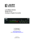
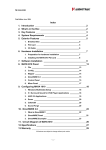
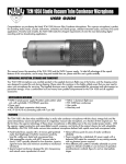
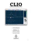
3 CLIO INSTALLATION
3.1 MINIMUM PC CONFIGURATION
The CLIO PC board running the CLIOwin software can be fitted in any IBM (or
compatible) personal computer with the following minimum system requirements:
–
–
–
–
–
–
–
Pentium processor (suggested minimum 133 MHz)
one free 8-bit or 16-bit half-size ISA slot
32 MB RAM
800x600 256 color video adapter
Microsoft Windows 95, 98, or ME (Millennium Edition)
Microsoft Internet Explorer 4.01
Adobe Acrobat Reader 4
3.2 HARDWARE INSTALLATION
Note: we strongly suggest you to read all this chapter before proceeding with
the hardware installation. Infact, should you need to change the jumper
settings to reflect system resources availability then you should repeat this
installation!
To install the CLIO board in your computer you should follow the instructions presented
below:
1) Disconnect the mains power cable from the PC.
2) Open the computer cabinet.
3) With the motherboard in front of you, identify a free 8-bit (or 16-bit) ISA slot. Note
that it is preferable to install the CLIO board as far away as possible from the video
adapter.
4) Insert the CLIO board in the slot and screw it down firmly.
5) Close the cabinet.
6) Reconnect the mains cable and switch the computer on.
At this point the CLIO board hardware installation is finished.
3.2.1 SOME MORE WORDS ABOUT THE HR-2000 CARD
The CLIO HR-2000 PC board is an ISA legacy hardware. This means:
1) CLIO needs, to operate, to be physically installed in a 100% compliant ISA slot.
2) Provided an ISA equipped computer meeting the minimum requirements given
before, CLIO can operate with any kind of processor, no matter how fast or new this
processor is. ISA compatibility, which is a well recognized industry standard,
guarantees CLIO’s functionality.
3) As the word ‘legacy’ implies, and as it is needed with all other ISA devices, the
installation in a Windows environment will go through some manual actions and
man-to-machine interactions, at least for changing the on-board jumper and, when
needed, for inspecting and modifying the computer BIOS settings. It is not possible
to have a 100% automatic and hassle-free installation since Windows is not able to
modify these settings.
Chapter 3 – Installation
21
3.2.2 PC SYSTEM RESOURCES REQUIRED
Before proceeding with the software installation please take note of the following
requirements.
The CLIO systems needs the following PC system resources:
1) The exclusive usage of DMA channels number 1 and 3.
2) A free I/O Address range selectable between the two possible: 300 HEX (using 300304 range) or 310 HEX (using 310-314 range)
No IRQ is needed.
It is possible to configure the I/O address of the CLIO board, by means of the JP2 jumper,
in order to avoid conflicts with other boards that are installed in your computer. Refer
to Fig.3.1 where you can see the two possible positions of JP2. The I/O space used by
CLIO is five bytes wide, and starts at the base address that has been selected (i.e. 300304 HEX if the 300 HEX choice has been made). The situation depicted in Fig.3.1a is
the factory default.
FIGURE 3.1a – I/O address 300 HEX
FIGURE 3.1b – I/O address 310 HEX
Jumper JP1 has no effect either on the installation or the current software functionality;
it has to be left as factory shipped.
3.3 SOFTWARE INSTALLATION AND HARDWARE REGISTRATION
This paragraph deals with software installation and hardware registration. Please
note that these two steps are distinct and separate; while the first is carried out simply
running an automatic procedure the second is a manual procedure that requests you
to interact with the Windows operating system.
The CLIOwin software is provided either on its own CD-ROM or, in electronic format,
as a single, self-extracting, executable file.
Figure 3.2
In the first case the CD-ROM root will contain a file named setup.exe while in the second
the file will be named with your system's serial number (41947124.exe as in Fig. 3.2);
click on these files to start the software installation as in Fig.3.3.
The procedure is completely automatic and will only request you to accept the Software
End User's License Agreement and input some information in order to correctly install
CLIOWin; the software installer will also check your operating system version and, in
certain cases, will request you to restart Windows in order to finalise the installation.
22
Chapter 3 – Installation
Figure 3.3
After completing successfully this procedure you are ready to go for the hardware
registration of your CLIO board. Take note of the installation directory of CLIOwin
(usually C:\Program Files\Audiomatica\Cliowin).
Please don't run CLIOwin now! The software is already installed but your CLIO
hardware has not been registered with Windows yet. You would surely obtain
an error message and your software won't run correctly.
The procedures described refer directly (and are described with examples and figures)
to the Windows 98 SE operating system, English version; they can be applied with only
minor modifications and appropriate translations to all the other OS and languages.
Let's first inspect the availability of your PC system resources:
Click with the right mouse button on the 'My Computer' icon on the Windows desktop.
Then click 'Properties' and select the 'Device Manager' tab as in Fig. 3.4.
Figure 3.4
Chapter 3 – Installation
23
Double click on 'Computer'. The Computer properties dialog box appears. Select Direct
Memory Access (DMA). Then Select Input/Output. Refer to Fig.3.5.
Figure 3.5
The two panels above are of fundamental help since they let you understand what other
hardware may conflict with the CLIO board. As said in 3.2.2 CLIO needs DMA channel
1, DMA channel 3 and I/O at either 300Hex or 310Hex. In the example of Fig. 3.5 you
can see that I/O is free but DMA channel 3 is taken by an MS Windows Sound System
Compatible card: this is a conflict! And you must resolve it otherwise your CLIO
hardware will not work.
Resolving a conflict means to free the resources that CLIO needs; when the conflict is
hardware you usually need to act manually on the conflicting peripheral and try to
reconfigure it, assigning different resources to it. In the example above, you may try
to assign DMA channel 0 to the MS Sound System (if supported). If you cannot find a
way to resolve the conflict you are obliged to disable or remove it. Sometimes there are
what we can call 'apparent' conflicts with some sort of Device Drivers (like legacy sound
blaster emulators) or with particularly smart hardware; in these cases Windows does
the job for you and, as soon as it finds the CLIO card requesting for certain resources,
will free them and be able to configure the other driver or hardware.
In any case you have to go through the 'Add New Hardware Wizard' and try to register
CLIO with Windows. Follow this procedure; enter the Control Panel from the Start Menu
and then run the Add New Hardware Wizard, as in Fig.3.6.
Figure 3.6
24
Chapter 3 – Installation
The Wizard will first try to locate the Plug&Play Devices in your system. Choose 'No, the
device isn't in the list'. At the following prompt choose 'No, I want to select the hardware
from a list'.
Figure 3.5
Select ‘Sound, video and game controllers’ from the Hardware types list. Then click
Next. Then Press the ‘Have Disk...’ button.
Figure 3.6
Press the ‘’Browse...’’ button. Select the ‘C:\Program Files\Audiomatica\Cliowin’ folder
(or the installation directory you chose). Choose the clio.inf file.
Figure 3.7
Chapter 3 – Installation
25
Choose the ‘Clio HR-2000’ hardware and follow the instruction. Windows will now tell
you if it was able to assign CLIO the requested resources.
Figure 3.8
In case of success you will receive a message like the one in Fig.3.8. Windows will then
complete the procedure and restart your PC.
Only then you can consider the installation completed and run CLIOwin. Skip
the following paragraph and proceed using CLIO for the first time.
Should you receive a warning message you need to suffer a little more... Windows may
tell you that it cannot assign CLIO the requested resources and indicate you what
hardware is conflicting. At this time you have to through again the procedure described
in this paragraph after Windows has rebooted. Take note of all messages that Windows
tells you; keep in mind that you can configure your CLIO card by moving the JP2 in order
to select one of the two possible I/O ranges. Read the following chapter for a more
detailed discussion of possible conflicts.
3.3.1 CAUSES OF CONFLICT
The causes of conflict may be divided in two main categories: peripherals integrated on
your main PC board or add-on cards inserted in your mainboard's ISA expansion slots.
It is very unlikely that a PCI expansion card is conflicting with CLIO. To troubleshoot your
installation you need to locate the conflicting hardware and either reconfigure, disable
or remove it.
The on-board conflicting integrated peripherals may be:
1) Parallel ports configured in ECP mode
2) Infrared serial ports
3) Audio subsystems
To check if any on-board peripheral is conflicting you have to access your PC's BIOS
settings. This is usually accomplished pressing a particular key or sequence of keys
while your PC is booting; any PC is telling the user which is the correct key to press to
enter BIOS: the most common is the ‘Del’ key but you may need to press ‘F2’ or a
different one.
When inside BIOS you should locate a menu like ‘INTEGRATED PERIPHERALS’ inside
which there are listed the peripherals present and their settings.
The conflicting ISA add-on cards may be:
1) Sound cards
26
Chapter 3 – Installation
2) Network cards
3) Expansion parallel ports
4) SCSI controllers
The main difference with the preceding case when an on-board peripheral was
conflicting is that an expansion card may be, for testing purposes, physically removed.
This is a quick way for isolating the cause of problems and assessing CLIO's
functionality.
In
1)
2)
3)
our experience the vast majority of conflicts are generated by:
On-board parallel ports configured in ECP mode using DMA channel 1 or 3.
ISA sound cards or on-board audio subsystems using DMA channel 1 or 3.
ISA network cards using I/O address 300.
Chapter 3 – Installation
27
3.4 RUNNING CLIOWIN FOR THE FIRST TIME
If you have completed the preceding installation procedure, you are ready to run
CLIOwin!
The steps hereafter described will guide you through a complete verification
of the system performance and operation.
3.4.1 INITIAL TEST
Please, take some time to familiarize with your CLIO board and its four RCA plugs. The
two upper ones are the input (A and B), while the lower twos are the output (A and B).
INPUT A
INPUT B
OUTPUT A
OUTPUT B
The board has to be connected as depicted in Fig. 3.9 (with input A and output A shortcircuited); do not change this connection throughout all the tests described in this
section.
INPUT A
CLIO
INPUT B
OUTPUT A
OUTPUT B
Figure 3.9
From the Start Menu choose Programs, then CLIOwin and click on the CLIOwin icon.
The program should start smoothly and present the main desktop (see 5.3); should it
display an error message take note of it and go to the troubleshooting section.
Let's now execute our first test measurement: play and capture an 1kHz sinusoid. Click
to play the 1kHz sinusoid (it's the default signal). Then press
on the generator icon
the F4 keystroke to invoke the Multi-Meter as in Fig.3.10.
28
Chapter 3 – Installation
Figure 3.10
If everything is OK you should obtain a reading of circa 0.77V (-2.2dBV) which is the
default output level of a sinusoidal signal.
To conclude your intial test execute the calibration procedure described in the following
section.
Chapter 3 – Installation
29
3.5 SYSTEM CALIBRATION
This section describes how to perform the system calibration.
Connect Output A with Input A, referring to Fig.3.9.
Be sure that, any time you perfom a calibration, the system has warmed up for, at least,
15/20 minutes.
Select Calibration from the File menu (6.3.5); answer yes to the initial prompt; this
will run an automatic procedure that will last several minutes. The calibration procedure
is completely automatic and several progress indicators will accompany all the executed
measurements. At the end of it your CLIO system should be calibrated and ready to
execute measurements.
At the end of the calibration process it is always mandatory to verify the calibration itself;
this is done by two simple measurements as described in the following section.
3.5.1 CALIBRATION VALIDATION
Figure 3.11
To verify the calibration first check that the generator output level is set to 0dBu (refer
to 5.4.2 for details).
Then click on the MLS button
to invoke the MLS control panel. Press the Go
button
to execute an MLS frequency response measurement; after about 1 second you should
obtain the desired result, a straight line (blue) as in Fig.3.11. You can click on the graph
and inspect the amplitude of the measured signal: you should obtain a reading around
30
Chapter 3 – Installation
-5.2dBV, this is the correct output level of the MLS signal with the generator output set
to 0dBu.
Then click on the Sinusoidal button
to invoke the Sinusoidal control panel as in
button to execute a Sinusoidal frequency response
Fig.3.11. Press the Go
measurement; after about 25 seconds you should obtain the desired result, again a
straight line (blue) as in Fig.3.11. You can click on the graph and inspect the amplitude
of the measured signal: you should obtain a reading around -2.2dBV, this is the correct
output level of the sinusoidal signal with the generator output set to 0dBu.
To assess a 100% correct calibration you need also to inspect phase responses of both
and verify that you obtain a
measurements. To do this press the phase button
straight line (red curves in Fig.3.11) also for phase responses; the readings in this case
should be around zero degrees in both cases.
Chapter 3 – Installation
31
3.6 CLIO SERIAL NUMBER AND DEMO MODE
Each CLIO system has its own serial number which plays an important role since the
CLIOwin software is hardware protected and relies on a correct serialization in order to
run.
If the CLIOwin software doesn't find an HR-2000 board installed with a correct serial
number gives a warning message and enters what is a called a DEMO mode; in this
way it is possible to run CLIOwin also in a PC where there is not installed the CLIO
hardware and perform postprocessing and other off line jobs.
To find the serial number of your CLIO system refer to Fig.3.12 below, inspect the HR2000 PC board and read the number written on the black square chip (U9) right in the
center of the board itself. Please take note of this number and always tell it to
Audiomatica when requesting assistance or upgrading software.
Figure 3.12
32
Chapter 3 – Installation