1
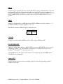
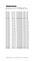
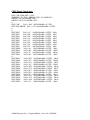
Craignell User Manual
Issue – 1.01
©2008 Enterpoint Ltd. – Craignell Manual – Issue 1.01 25/01/2008
Kit Contents
You should receive the following items with you Craignell development kit:
1 – Craignell CR28/CR32/CR36/CR40 Board.
Purchase Optional Extras
The following, or equivalent, are necessary to program a Craignell module.
1 – Prog2 Programming Cable.
2 – Craignell Programming Adaptor
We also have ZIF based module to power a Craignell outside of a target board to
allow programming. Contact [email protected] for more details on this
item.
©2008 Enterpoint Ltd. – Craignell Manual – Issue 1.01 25/01/2008
Foreword
PLEASE READ THIS ENTIRE MANUAL BEFORE PLUGGING IN
OR POWERING UP YOUR CRAIGNELL BOARD.
PLEASE TAKE SPECIAL NOTE OF THE WARNINGS WITHIN
THIS MANUAL.
Trademarks
Coolrunner-II, Spartan, ISE, EDK, Webpack, Xilinx are the registered trademarks of Xilinx Inc,
San Jose, California, US.
Craignell is a trademark of Enterpoint Ltd.
©2008 Enterpoint Ltd. – Craignell Manual – Issue 1.01 25/01/2008
Introduction
Welcome to your Craignell board. Craignell is a low cost high performance SpartanTM-3E FPGA
based module.
This manual covers Issue2 and later of the Craignell modules. If you need information on Issue1 the
schematics are available at http://www.enterpoint.co.uk/component_replacements/craignell.html.
The aim of this manual is to assist in using the main features of Craignell. Should this manual fail to
explain a feature sufficiently then our support team can be reached by email on
[email protected].
©2008 Enterpoint Ltd. – Craignell Manual – Issue 1.01 25/01/2008
Finding Your Way Around
Getting Started
Craignell is currently available in 4 pinout sizes – 28 pins, 32 pins, 36 pins and 40 pins.
Your Craignell normally comes with our LED Flash Test build loaded. This application will cause
the LED to flash on and off and indicates power is applied, the on-board oscillator is running and
the FPGA has configured from the on-board SPI Flash Memory.
Pin1 of the module is on the back side of the module at the top left of the picture above (CR40).
Pins count counter-clockwise from Pin1.
Some useful links and other information can be obtained from our website here:
http://www.enterpoint.co.uk/techitips/techitips.html
©2008 Enterpoint Ltd. – Craignell Manual – Issue 1.01 25/01/2008
Craignell Features
Power Inputs and Power Supplies
Craignell uses a notional 5V input but can operate from 3.5V to 5.5V (specification guaranteed) but
in practise can operate as low as 2.8V and as high as 6V if care in interfacing signal levels is taken.
An optimised version for 3.3V power supply operation will be available shortly. Please contact
sales if you are interested in this version or require more information.
The power is supplied to the module on the top right pin – 5V (facing from the front of the module
and most components visible) and the bottom left pin - 0V/GND. We can supply other variants of
power pinning as special builds for component replacements with differing requirements. Input
current requirements will depend on the design loaded into the FPGA on the board, the size of the
FPGA, and I/O loading. We would normally expect this would be in the range 100-500mA.
An onboard a Texas Instruments TPS70402 linear regulator produces 1.22V and 2.5V from the
input supply voltage. The 1.22V is used for the SpartanTM-3E core voltage and the 2.5V is used for
all other devices and for the Vccaux/Bank Voltages of SpartanTM-3E.
WARNING – THE REGULATORS CAN POTENTIALLY GET
VERY HOT IN SOME UNUSUAL CIRCUMSTANCES ALONG
WITH THE BOARDS THERMAL RELIEF. PLEASE DO NOT
TOUCH OR PLACE HIGHLY FLAMABLE MATERIALS NEAR
THIS DEVICE WHILST THE CRAIGNELL BOARD IS IN
OPERATION.
©2008 Enterpoint Ltd. – Craignell Manual – Issue 1.01 25/01/2008
Selecting the FPGA Bank (VCCIOX) voltages.
Craignell fixes the I/O voltages all of FPGA banks to 2.5V. However there are pull-ups to all the
I/O pins on the Gull-Wing Connectors to the input supply voltage allow the I/O to achieve CMOS
type levels were these are needed.
©2008 Enterpoint Ltd. – Craignell Manual – Issue 1.01 25/01/2008
Programming Craignell
For programming and building your design you will need to download a copy of ISE WebpackTM
form XilinxTM. You can obtain it here:
http://www.xilinx.com/ise/logic_design_prod/webpack.htm
The programming of the FPGA and Serial Flash parts on Craignell are achieved using 2 separate
interfaces. Both of these interfaces are accessed through a single 2x6 1.27mm header. Our Craignell
Programming Adaptor which breaks out these interfaces into two standard 2x7 2mm headers for use
with out Prog2 cable or Xilinx programming cables. The picture below shows their interface
locations. Please take special note of the orientation and alignment of the Programming adaptor
shown in the photograph below.
The first interface is a standard JTAG port which follows the standard layout for our Prog2 cable
and for Xilinx Programming Cables IV and later. The Xilinx ISE Impact tool can be used to control
programming (boundary scan mode). ISE Webpack can be downloaded free from Xilinx on their
website. Direct JTAG programming is volatile and the FPGA will lose its configuration every time
the board power is turned off/on. From sustained use of FPGA design programming the design into
the Serial Flash memory is recommended. Generation of suitable Serial Flash content files and
control of the JTAG chain can be achieved using the ISE Impact.
The second interface contains the signals that connect to Serial Flash and additionally Prog_B.
When a Prog2 or suitable Xilinx cable is plugged in Prog_B is connected to DGND/0V and the
SpartanTM-3E FPGA is placed into the pre-configured state. This avoids conflicts on the Serial
Flash control and data lines with drive from the programming cable. The pinout of the header also
©2008 Enterpoint Ltd. – Craignell Manual – Issue 1.01 25/01/2008
allows ISE Impact tool (serial flash mode) to program the Serial Flash. Please note to allow the
FPGA to configure you must remove the programming cable from the Serial Flash Programming
Header.
©2008 Enterpoint Ltd. – Craignell Manual – Issue 1.01 25/01/2008
FPGA
Craignell supports SpartanTM-3E devices in the CP/CPG132 package. Standard builds of Craignell
use commercial grade devices but industrial grade parts can be fitted at extra cost subject to
minimum order quantities and charges. Currently we are supplying only the XC3S100E-4CPG132C
and XC3S500E-4CPG132C FPGAs as standard options. The XC3S250E-4CPG132C is also
possible.
LEDS
Supplied on Craignell there is 1 LED driven by the FPGA. LED1 has a positive polarity i.e. ‘1’ =
on. LED2 and LED3 are negative polarity i.e. ‘0’ = on.
The LEDS are situated on FPGA IO pins as indicated below:
LED
FPGA
PIN
LED1
C14
CLOCK
Craignell comes fitted with a 40 MHz oscillator. This is input on FPGA pin M6.
FLASH MEMORY
Supplied as standard on Craignell is a 4Mbit ST Microelectronics M25P40. This device is used to
configure the SpartanTM-3E. The remainder of flash memory is available for storing code for
PicoBlazeTM, MicroBlazeTM or other microprocessors.
A XC3S100E will use 581,344 bits of this memory for configuration. The XC3S500E will use
2,270,208 bits for configuration.
General I/O
Craignell supports between twenty six and thirty eight 5V tolerant, I/O depending on which
Craignell you purchase.
©2008 Enterpoint Ltd. – Craignell Manual – Issue 1.01 25/01/2008
CR40 Pinout Constraints
NET "CLK"
LOC = "M6" | IOSTANDARD = LVTTL;
NET "LED_DRIVE" LOC = "C14" | IOSTANDARD = LVTTL;
#
#
NET "PIN1"
LOC="B9" | IOSTANDARD = LVTTL ;# IO9
NET "PIN2"
LOC="A7" | IOSTANDARD = LVTTL ;# IO8
NET "PIN3"
LOC="B5" | IOSTANDARD = LVTTL ;# IO7
NET "PIN4"
LOC="C6" | IOSTANDARD = LVTTL ;# IO6
NET "PIN5"
LOC="C3" | IOSTANDARD = LVTTL ;# IO5
NET "PIN6"
LOC="C5" | IOSTANDARD = LVTTL ;# IO4
NET "PIN7"
LOC="B1" | IOSTANDARD = LVTTL ;# IO0
NET "PIN8"
LOC="G1" | IOSTANDARD = LVTTL ;# IO1
NET "PIN9"
LOC="F3" | IOSTANDARD = LVTTL ;# IO2
NET "PIN10"
LOC="A3" | IOSTANDARD = LVTTL ;# IO3
NET "PIN11"
LOC="H3" | IOSTANDARD = LVTTL ;# IO35
NET "PIN12"
LOC="J3" | IOSTANDARD = LVTTL ;# IO36
NET "PIN13"
LOC="H1" | IOSTANDARD = LVTTL ;# IO37
NET "PIN14"
LOC="F1" | IOSTANDARD = LVTTL ;# IO34
NET "PIN15"
LOC="M4" | IOSTANDARD = LVTTL ;# IO38
NET "PIN16"
LOC="L3" | IOSTANDARD = LVTTL ;# IO26
NET "PIN17"
LOC="P4" | IOSTANDARD = LVTTL ;# IO33
NET "PIN18"
LOC="M5" | IOSTANDARD = LVTTL ;# IO32
NET "PIN19"
LOC="P6" | IOSTANDARD = LVTTL ;# IO31
NET "PIN21"
LOC="P7" | IOSTANDARD = LVTTL ;# IO30
NET "PIN22"
LOC="M12" | IOSTANDARD = LVTTL ;# IO28
NET "PIN23"
LOC="L14" | IOSTANDARD = LVTTL ;# IO27
NET "PIN24"
LOC="N14" | IOSTANDARD = LVTTL ;# IO25
NET "PIN25"
LOC="H12" | IOSTANDARD = LVTTL ;# IO24
NET "PIN26"
LOC="J12" | IOSTANDARD = LVTTL ;# IO23
NET "PIN27"
LOC="G13" | IOSTANDARD = LVTTL ;# IO20
NET "PIN28"
LOC="J14" | IOSTANDARD = LVTTL ;# IO21
NET "PIN29"
LOC="K14" | IOSTANDARD = LVTTL ;# IO22
NET "PIN30"
LOC="C12" | IOSTANDARD = LVTTL ;# IO16
NET "PIN31"
LOC="F12" | IOSTANDARD = LVTTL ;# IO17
NET "PIN32"
LOC="F14" | IOSTANDARD = LVTTL ;# IO18
NET "PIN33"
LOC="F2" | IOSTANDARD = LVTTL ;# IO19
NET "PIN34"
LOC="G14" | IOSTANDARD = LVTTL ;# IO15
NET "PIN35"
LOC="A13" | IOSTANDARD = LVTTL ;# IO14
NET "PIN36"
LOC="A10" | IOSTANDARD = LVTTL ;# IO13
NET "PIN37"
LOC="C9" | IOSTANDARD = LVTTL ;# IO12
NET "PIN38"
LOC="G3" | IOSTANDARD = LVTTL ;# IO11
NET "PIN39"
LOC="A9" | IOSTANDARD = LVTTL ;# IO10
©2008 Enterpoint Ltd. – Craignell Manual – Issue 1.01 25/01/2008
CR36 Pinout Constraints
NET "CLK" TNM_NET = "CLK";
TIMESPEC "TS_CLK" = PERIOD "CLK" 25 ns HIGH 50 %;
OFFSET = IN 3 ns BEFORE "CLK" ;
OFFSET = OUT 8.5 ns AFTER "CLK" ;
#
NET "CLK"
LOC = "M6" | IOSTANDARD = LVTTL;
NET "LED_DRIVE" LOC = "C14" | IOSTANDARD = LVTTL;
#
#
NET "PIN1"
LOC="B9" | IOSTANDARD = LVTTL ; #IO9
NET "PIN2"
LOC="A7" | IOSTANDARD = LVTTL ; #IO8
NET "PIN3"
LOC="B5" | IOSTANDARD = LVTTL ; #IO7
NET "PIN4"
LOC="C6" | IOSTANDARD = LVTTL ; #IO6
NET "PIN5"
LOC="C3" | IOSTANDARD = LVTTL ; #IO5
NET "PIN6"
LOC="C5" | IOSTANDARD = LVTTL ; #IO4
NET "PIN7"
LOC="B1" | IOSTANDARD = LVTTL ; #IO0
NET "PIN8"
LOC="G1" | IOSTANDARD = LVTTL ; #IO1
NET "PIN9"
LOC="F3" | IOSTANDARD = LVTTL ; #IO2
NET "PIN10"
LOC="A3" | IOSTANDARD = LVTTL ; #IO3
NET "PIN11"
LOC="H3" | IOSTANDARD = LVTTL ; #IO35
NET "PIN12"
LOC="J3" | IOSTANDARD = LVTTL ; #IO36
NET "PIN13"
LOC="H1" | IOSTANDARD = LVTTL ; #IO37
NET "PIN14"
LOC="F1" | IOSTANDARD = LVTTL ; #IO34
NET "PIN15"
LOC="M4" | IOSTANDARD = LVTTL ; #IO38
NET "PIN16"
LOC="L3" | IOSTANDARD = LVTTL ; #IO26
NET "PIN17"
LOC="P4" | IOSTANDARD = LVTTL ; #IO33
#
NET "PIN19"
LOC="L14" | IOSTANDARD = LVTTL ; #IO27
NET "PIN20"
LOC="N14" | IOSTANDARD = LVTTL ; #IO25
NET "PIN21"
LOC="H12" | IOSTANDARD = LVTTL ; #IO24
NET "PIN22"
LOC="J12" | IOSTANDARD = LVTTL ; #IO23
NET "PIN23"
LOC="G13" | IOSTANDARD = LVTTL ; #IO20
NET "PIN24"
LOC="J14" | IOSTANDARD = LVTTL ; #IO21
NET "PIN25"
LOC="K14" | IOSTANDARD = LVTTL ; #IO22
NET "PIN26"
LOC="C12" | IOSTANDARD = LVTTL ; #IO16
NET "PIN27"
LOC="F12" | IOSTANDARD = LVTTL ; #IO17
NET "PIN28"
LOC="F14" | IOSTANDARD = LVTTL ; #IO18
NET "PIN29"
LOC="F2" | IOSTANDARD = LVTTL ; #IO19
NET "PIN30"
LOC="G14" | IOSTANDARD = LVTTL ; #IO15
NET "PIN31"
LOC="A13" | IOSTANDARD = LVTTL ; #IO14
NET "PIN32"
LOC="A10" | IOSTANDARD = LVTTL ; #IO13
NET "PIN33"
LOC="C9" | IOSTANDARD = LVTTL ; #IO12
NET "PIN34"
LOC="G3" | IOSTANDARD = LVTTL ; #IO11
NET "PIN35"
LOC="A9" | IOSTANDARD = LVTTL ; #IO10 .
©2008 Enterpoint Ltd. – Craignell Manual – Issue 1.01 25/01/2008
CR32 Pinout Constraints
NET "CLK" TNM_NET = "CLK";
TIMESPEC "TS_CLK" = PERIOD "CLK" 25 ns HIGH 50 %;
OFFSET = IN 3 ns BEFORE "CLK" ;
OFFSET = OUT 8.5 ns AFTER "CLK" ;
#
NET "CLK"
LOC = "M6" | IOSTANDARD = LVTTL;
NET "LED_DRIVE" LOC = "C14" | IOSTANDARD = LVTTL;
#
#
NET "PIN1"
LOC="B9" | IOSTANDARD = LVTTL ; #IO9
NET "PIN2"
LOC="A7" | IOSTANDARD = LVTTL ; #IO8
NET "PIN3"
LOC="B5" | IOSTANDARD = LVTTL ; #IO7
NET "PIN4"
LOC="C6" | IOSTANDARD = LVTTL ; #IO6
NET "PIN5"
LOC="C3" | IOSTANDARD = LVTTL ; #IO5
NET "PIN6"
LOC="C5" | IOSTANDARD = LVTTL ; #IO4
NET "PIN7"
LOC="B1" | IOSTANDARD = LVTTL ; #IO0
NET "PIN8"
LOC="G1" | IOSTANDARD = LVTTL ; #IO1
NET "PIN9"
LOC="F3" | IOSTANDARD = LVTTL ; #IO2
NET "PIN10"
LOC="A3" | IOSTANDARD = LVTTL ; #IO3
NET "PIN11"
LOC="H3" | IOSTANDARD = LVTTL ; #IO35
NET "PIN12"
LOC="J3" | IOSTANDARD = LVTTL ; #IO36
NET "PIN13"
LOC="H1" | IOSTANDARD = LVTTL ; #IO37
NET "PIN14"
LOC="F1" | IOSTANDARD = LVTTL ; #IO34
NET "PIN15"
LOC="M4" | IOSTANDARD = LVTTL ; #IO38
#
NET "PIN17"
LOC="H12" | IOSTANDARD = LVTTL ; #IO24
NET "PIN18"
LOC="J12" | IOSTANDARD = LVTTL ; #IO23
NET "PIN19"
LOC="G13" | IOSTANDARD = LVTTL ; #IO20
NET "PIN20"
LOC="J14" | IOSTANDARD = LVTTL ; #IO21
NET "PIN21"
LOC="K14" | IOSTANDARD = LVTTL ; #IO22
NET "PIN22"
LOC="C12" | IOSTANDARD = LVTTL ; #IO16
NET "PIN23"
LOC="F12" | IOSTANDARD = LVTTL ; #IO17
NET "PIN24"
LOC="F14" | IOSTANDARD = LVTTL ; #IO18
NET "PIN25"
LOC="F2" | IOSTANDARD = LVTTL ; #IO19
NET "PIN26"
LOC="G14" | IOSTANDARD = LVTTL ; #IO15
NET "PIN27"
LOC="A13" | IOSTANDARD = LVTTL ; #IO14
NET "PIN28"
LOC="A10" | IOSTANDARD = LVTTL ; #IO13
NET "PIN29"
LOC="C9" | IOSTANDARD = LVTTL ; #IO12
NET "PIN30"
LOC="G3" | IOSTANDARD = LVTTL ; #IO11
NET "PIN31"
LOC="A9" | IOSTANDARD = LVTTL ; #IO10
©2008 Enterpoint Ltd. – Craignell Manual – Issue 1.01 25/01/2008
CR28 Pinout Constraints
NET "CLK" TNM_NET = "CLK";
TIMESPEC "TS_CLK" = PERIOD "CLK" 25 ns HIGH 50 %;
OFFSET = IN 5 ns BEFORE "CLK" ;
OFFSET = OUT 15 ns AFTER "CLK" ;
#
NET "CLK"
LOC = "M6" | IOSTANDARD = LVTTL;
NET "LED_DRIVE" LOC = "C14" | IOSTANDARD = LVTTL;
#
#
NET "PIN2"
LOC="A7" | IOSTANDARD = LVTTL ; #IO8
NET "PIN3"
LOC="B5" | IOSTANDARD = LVTTL ; #IO7
NET "PIN4"
LOC="C6" | IOSTANDARD = LVTTL ; #IO6
NET "PIN5"
LOC="C3" | IOSTANDARD = LVTTL ; #IO5
NET "PIN6"
LOC="C5" | IOSTANDARD = LVTTL ; #IO4
NET "PIN7"
LOC="B1" | IOSTANDARD = LVTTL ; #IO0
NET "PIN8"
LOC="G1" | IOSTANDARD = LVTTL ; #IO1
NET "PIN9"
LOC="F3" | IOSTANDARD = LVTTL ; #IO2
NET "PIN10"
LOC="A3" | IOSTANDARD = LVTTL ; #IO3
NET "PIN11"
LOC="H3" | IOSTANDARD = LVTTL ; #IO35
NET "PIN12"
LOC="J3" | IOSTANDARD = LVTTL ; #IO36
NET "PIN13"
LOC="H1" | IOSTANDARD = LVTTL ; #IO37
#
NET "PIN15"
LOC="H12" | IOSTANDARD = LVTTL ; #IO23
NET "PIN16"
LOC="J12" | IOSTANDARD = LVTTL ; #IO20
NET "PIN17"
LOC="G13" | IOSTANDARD = LVTTL ; #IO21
NET "PIN18"
LOC="J14" | IOSTANDARD = LVTTL ; #IO22
NET "PIN19"
LOC="K14" | IOSTANDARD = LVTTL ; #IO16
NET "PIN20"
LOC="C12" | IOSTANDARD = LVTTL ; #IO17
NET "PIN21"
LOC="F12" | IOSTANDARD = LVTTL ; #IO18
NET "PIN22"
LOC="F14" | IOSTANDARD = LVTTL ; #IO19
NET "PIN23"
LOC="F2" | IOSTANDARD = LVTTL ; #IO15
NET "PIN24"
LOC="G14" | IOSTANDARD = LVTTL ; #IO14
NET "PIN25"
LOC="A13" | IOSTANDARD = LVTTL ; #IO13
NET "PIN26"
LOC="A10" | IOSTANDARD = LVTTL ; #IO12
NET "PIN27"
LOC="C9" | IOSTANDARD = LVTTL ; #IO11
©2008 Enterpoint Ltd. – Craignell Manual – Issue 1.01 25/01/2008
Medical and Safety Critical Use
Craignell boards are not authorised for the use in, or use in the design of, medical or other safety
critical systems without the express written person of the Board of Enterpoint. If such use is
allowed the said use will be entirely the responsibility of the user. Enterpoint Ltd will accept no
liability for any failure or defect of the Craignell board, or its design, when it is used in any medical
or safety critical application.
Warranty
Craignell comes with a 90 return to base warranty.
Other specialised warranty programs can be offered to users of multiple Enterpoint products. Please
contact sales on [email protected] if you are interested in these types of warranty,
Support
Enterpoint offers support during normal United Kingdom working hours 9.00am to 5.00pm. Please
examine our Craignell FAQ web page and the contents of this manual before raising a support
query. We can be contacted as follows:
Telephone
Email
- +44 (0) 1684 585262
- [email protected]
©2008 Enterpoint Ltd. – Craignell Manual – Issue 1.01 25/01/2008