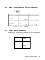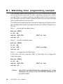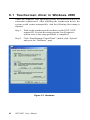
1
GOT-1150T Fanless Touch Panel Computer with 15" TFT LCD User's Manual Disclaimers The information in this manual has been carefully checked and is believed to be accurate. AXIOMTEK Co., Ltd. assumes no responsibility for any infringements of patents or other rights of third parties which may result from its use. AXIOMTEK assumes no responsibility for any inaccuracies that may be contained in this document. AXIOMTEK makes no commitment to update or to keep current the information contained in this manual. AXIOMTEK reserves the right to make improvements to this document and/ or product at any time and without notice. No part of this document may be reproduced, stored in a retrieval system, or transmitted, in any form or by any means, electronic, mechanical, photocopying, recording, or otherwise, without the prior written permission of AXIOMTEK Co., Ltd. Copyright 2003 by AXIOMTEK Co., Ltd. All rights reserved. December. 2003, Version 1.0 Printed in Taiwan ii Trademarks Acknowledgments AXIOMTEK is a trademark of AXIOMTEK Co., Ltd. IBM is a registered trademark of International Business Machines Corporation. MS-DOS, Microsoft C and QuickBasic are trademarks of Microsoft Corporation. TURBO C is a trademark of Borland Inc. BASIC is a trademark of Dartmouth College. Intel is a trademark of Intel Corporation. Other brand names and trademarks are the properties and registered brands of their respective owners. iii ESD Precautions Integrated circuits on computer boards are sensitive to static electricity. To avoid damaging chips from electrostatic discharge, observe the following precautions: n Do not remove boards or integrated circuits from their anti-static packaging until you are ready to install them. n Before handling a board or integrated circuit, touch an unpainted portion of the system unit chassis for a few seconds. This helps to discharge any static electricity on your body. n Wear a wrist-grounding strap, available from most electronic component stores, when handling boards and components. Packing List In the whole set of GOT-1150T there are items as listed below: 1. GOT-1150T x 1 unit 2. Accessory kit which includes: (1) HDD cover screws x 4 pieces and 1 spare piece (2) HDD cushions x 4 pieces and 1 spare piece (3) Panel mounting clamper x 10 pieces and 1 spare piece (4) Panel mounting screws x 10 pieces and 1 spare piece (5) PC/104 plus expansion board standoff x 4 pieces (6) 3-pin power connector x 1 piece (7) GOT-1150T support CD x 1 piece (8) 1 meter 9-pin to 9-pin null modem cable x 1 piece*1 (9) Y-cable x 1 piece to simultaneously connect mouse and keyboard (10) CompactFlashTM to IDE adapter board x 1 piece (11) 44-40-40 pins IDE cable x 1 piece iv Safety Instructions 1. Read these safety instructions carefully. 2. Keep this installation reference guide for later reference. 3. Disconnect this equipment from any AC outlet before cleaning. Do not use liquid or spray detergents for cleaning. Use a damp cloth. 4. For pluggable equipment, the power outlet must be installed near the equipment and must be easily accessible. 5. Keep this equipment away from humidity. 6. Put this equipment on a reliable surface during installation. Dropping it or letting it fall could cause damage. 7. The openings on the enclosure are for air convection. Protect the equipment from overheating. DO NOT COVER THE OPENINGS. 8. Make sure the voltage of the power source is correct before connecting the equipment to the power outlet. 9. Position the power cord so that people cannot step on it. Do not place anything over the power cord. 10. All cautions and warnings on the equipment should be noted. 11. If the equipment is not used for a long time, disconnect it from the power source to avoid damage by transient over-voltage. 12. Never pour any liquid into an opening. This could cause fire or electrical shock. 13. Never open the equipment. For safety reasons, the equipment should be opened only by qualified service personnel. 14. If any of the following situations arises, get the equipment checked by service personnel: a. The power cord or plug is damaged. b. Liquid has penetrated into the equipment. c. The equipment has been exposed to moisture. d. The equipment does not work well, or you cannot get it to work according to the installation reference guide. e. The equipment has been dropped and damaged. f. The equipment has obvious signs of breakage. 15. DO NOT LEAVE THIS EQUIPMENT IN AN UNCONTROLLED ENVIRONMENT WHERE THE STORAGE TEMPERATURE IS BELOW -20•‹ C (-4•‹ F) OR ABOVE 60•‹ C (140•‹ F). IT MAY DAMAGE THE EQUIPMENT. The sound pressure level at the operator•fs position according to IEC 704-1:1982 is equal to or less than 70 dB(A) v Table of Contents Chapter 1 General Information ........................... 1 1.1 Introduction .................................................................... 2 1.2 3 3 3 4 4 5 1.4 Touchscreen specifications .......................................... 6 1.5 Power .............................................................................. 6 1.6 I/O ports arrangement ................................................... 6 1.7 7 7 8 9 1.9 Dimensions and cutout ............................................... 10 Specifications................................................................. 1.2.1 System kernel ....................................................... 1.2.2 I/O ports ................................................................. 1.1.3 Storage .................................................................. 1.1.4 Safety and environment ....................................... 1.3 LCD specifications ........................................................ Mounting ......................................................................... 1.7.1 Panel mounting ..................................................... 1.7.2 Wall mounting/desktop stand .............................. 1.8 Exploded diagram .......................................................... Chapter 2 System Quick Starting ...................... 11 Chapter 3 The Engine of the GOT-1150T ........... 17 3.1 3.2 Introduction .................................................................. 18 Main board .................................................................... 18 3.2.1 Connector pin assingments .............................. 19 3.3 GOT-1150T I/O board ................................................... 20 vi Chapter 4 System Limitations ........................... 23 4.1 Compatibility with IBM MicroDrive ............................ 24 4.2 System Hibernation and Resuming ........................... 25 4.3 Compatibility with IDE CD-ROM Drives .................... 25 4.4 USB Devices ................................................................ 26 4.5 Power Management ..................................................... 26 Chapter 5 5.1 System Tuning ................................... 27 LCD contrast tuning .................................................... 5.1.1 LCD brightness tuning ...................................... 5.2 Touchscreen calibration .............................................. 5.2.1 DOS/Windows Family ........................................ Chapter 6 28 28 29 29 Maintenance ...................................... 31 6.1 CPU board replacement .............................................. 32 6.2 Fuse replacement ........................................................ 34 Appendix A Serial Port Settings ........................... 35 A.1 Baud Rate Settings (SW1) .......................................... 36 A.2 Data Format/RS-422 Control Settings ....................... 37 A.3 COM3 Mode Selecting ................................................. 37 Appendix B Watchdog Timer Programming Example ............................................. 39 B.1 Watchdog timer programming example .................... 40 vii Appendix C Windows 2000 Touch Screen Installation ......................................... 41 C.1 Touchscreen driver in Windows 2000 ........................ 42 Appendix D Fuse Specifications ........................... 51 D. Fuse Specifications ..................................................... 52 Appendix E HDD Module Assembling/ Dismounting Guide ........................... 53 E.1 Item List ........................................................................ 54 E.2 Item List ........................................................................ 55 Appendix F BIOS Setting ...................................... 57 F.1 Boot Devices ................................................................ 58 F.2 PC Status Monitoring .................................................. 59 viii Figures Figure 1.6-1 Figure 1.7-1 Figure 1.8-1 Figure 1.9-1 I/O ports arrangement ............................................................. 7 Panel mounting ........................................................................ 7 Exploded diagram .................................................................... 9 Dimensions and cutout ......................................................... 10 Figure 2-1 Figure 2-2 Figure 2-3 Figure 2-4 Figure 2-5 Install CompactFlash memory card ..................................... 12 Power connector and power lines ....................................... 13 Power connector pin assignment ........................................ 13 Plug the power lines to the system power receptor. .......... 14 Turn on power switch ............................................................ 14 Figure 3.2-1 GOT-1150T main board .......................................................... 18 Figure 3.3-1 GOT-1150T I/O board .............................................................. 20 Figure 5.1-1 Adjust LCD contrast ............................................................... 28 Figure 5.1-2 Remove the CPU Board cover ............................................... 28 Figure 5.1-3 Adjusting the LCD brightness ............................................... 29 Figure 6.1-2 Figure 6.1-1 Figure 6.1-3 Figure 6.2-1 Remove the CPU board cover ............................................... 32 CPU board cover .................................................................... 32 Remove the CPU board ......................................................... 33 Replace the fuse .................................................................... 34 Figure C-1 Figure C-2 Figure C-3 Figure C-4 Figure C-5 Figure C-6 Figure C-7 Figure C-8 Figure C-9 Hardware ................................................................................ 42 Device manager ..................................................................... 43 Uninstall the driver ................................................................. 44 Mouse properties .................................................................. 45 Update driver .......................................................................... 46 Select driver from known list ................................................ 47 Find out TouchScreen in the manufacturers list ................. 48 Re-install the driver ............................................................... 49 Finish installation of touchscreen driver .............................. 50 ix Tables Table 1.3-1 Table 1.4-1 LCD specifications ................................................................... 5 Touchscreen specifications ................................................... 6 Table 3.2-1 Table 3.2-2 Table 3.3-1 GOT-1150T main board connector/jumper list ..................... 18 J1 RTC control jumper ........................................................... 19 GOT-1150T I/O board connector/jumper list ........................ 21 x CHAPTER 1 General Information This chapter gives background information on the GOT-1150T. Sections include: • Introduction • Specifications • LCD Specifications • Touchscreen specifications • Power • I/O ports • Mounting • Exploded diagram • Dimensions and cutout 1.1 Introduction The GOT-1150T touch panel computer is a revolutionary product of HMI (Human Machine Interface). This 15” display operator interface is a x86-based platform with these key features: - All in on platform: the CPU, DRAM are integrated. It is a plug-andplay machine compared with those so-called panel PCs. - Slim but robust: the GOT-1150T is very thin (50 mm thickness); nevertheless its Mg-Al bezel provides amazing structural strength and EMI reduction. - Excellent display: the high brightness TFT LCD display fits the industrial demand well. - Fan-less and modular CPU board: the introduction of low power processor prevents this system from unreliable fans. In addition, the modular design facilitates the maintenance or possible upgrade on the CPU board. - Powerful communication capability: the GOT-1150T provides serial ports, parallel port, Ethernet, USB and PC/104 plus expansion slot. Almost all communications devices can access to this system. 2 GOT-1150T User's Manual 1.2 Specifications 1.2.1 System kernel - CPU: Transmeta CrusoeTM TM5400 (clock rate 500 MHz) - BIOS: Award 256 KB flash memory - South bridge: VIA 82C686B - VGA: Silicon Motion SMI710/712 VGA/LCD controller; PCI 2.1 compliant; 4 MB embedded DRAM - DRAM: built-in 128 MB SDRAM; among which 16 MB is occupied by CPU (Code Morphing TM Software) and the other 112 MB is avail-able for users - Ethernet: NS DP83815 10/100Base-T Ethernet controller; IEEE 802.3u protocol compatible - Watchdog timer: MAX706 watchdog timer; 1.6 second timeout period - IDE: 1 EIDE channel supports one 2.5” IDE HDD and one CompactFlash card simultaneously - Floppy diskette: External from USB 1.2.2 I/O ports - 1 RJ-45 Ethernet port - 1 parallel port: supports EPP/ECP modes - 1 DB-15 VGA out port - 2 audio jacks: one Line-Out for connecting external speakers, and one MIC for voice input - 1 PS/2 port: for external mice. It takes the Y-cable if simultaneous connection of mouse and keyboard is required - 2 USB ports - 3 serial ports: 2 DB-9 RS-232 (COM1/COM2), COM3 is a DIP switch configurable RS-232/422/485 port with automatic data flow control function Chapter 1 General Information 3 - 1 type-II CompactFlashTM slot - 2 type-II PCMCIA slots: supports IBM MicroDrive as data storage 1.1.3 Storage The GOT-1150T provides one EIDE channel for one 2.5” 44-pin HDD and one CompactFlash card. The system boot-up sequence is: 1. HDD and CompactFlash exist simultaneously: the system will boot from the HDD. The HDD must be set as master. If the HDD does not contain operating system, the GOT-1150T will automatically boot from the CompactFlash. 2. HDD exists only: the system will boot from the HDD 3. CompactFlash card exists only: the system will boot from the CompactFlash 4. The GOT-1150T also support IBM MicroDriveTM. However, a MicroDrive cannot be used as bootup device due to its intrinsic limitation. 1.1.4 Safety and environment Safety - FCC class A and CE certificated - BSMI certificated - The front bezel is compliant with NEMA 4 Environment - Operating temperature: 0~50 degrees Celsius - Storage temperature: -20~60 degrees Celsius - Humidity: 10~95% @ 40°C relative humidity (non-condensing) - Vibration: 10~18 Hz: 1.5mm peak-to-peak displacement; 18~500 Hz: at least 0.5 acceleration 4 GOT-1150T User's Manual 1.3 LCD specifications Display Type TFT color LCD Size (Diagonal) 15" Maximum Resolution 1024 x 768 (XGA) Maximum Colors 1677 million (true color) Pixel pitch (WxH, mm) 0.297 x 0.297 Vie wing angle 140 Luminance (cd/m2) 350 Contrast ratio 250 Operating temperature (°C) 0 ~ 50 (ambient) VR control Brightness adjustable Backlight 4 CCFL replaceable Backlight MTTF 50,000 hours Table 1.3-1 LCD specifications Notice: There might be several bright or dark pixels on the LCD. This comes from the production of the LCD. Such phenomenon is claimed to be normal according to the LCD manufacturers. Chapter 1 General Information 5 1.4 Touchscreen specifications Type Resistive Base glass construction Tempered Glass Resolution Continuous Light Transmission 75% typical Controller PS/2 interface Power Rating 3.3 to 5 VDC Software driver Windows 9x/Me/NT/2000; Windows CE (embedded) Durability 1 million touches for single point Table 1.4-1 Touchscreen specifications 1.5 Power - Input voltage: 24VDC (the fuse will be open circuit as input level exceeds 33VDC ) - Maximum current: 2 A 1.6 I/O ports arrangement The GOT-1150T has 3 serial ports, 2 parallel port, 1 USB port, 1 PS/2 port, 1 RJ-45 LAN port , 1 VGA port, 2 audio jacks, 2 PCMCIA slots and a PC/104+ expansion slot. The arrangement of these ports is shown in Figure 1.6-1. 6 GOT-1150T User's Manual Figure 1.6-1 I/O ports arrangement 1.7 Mounting 1.7.1 Panel mounting 1. There is a piece of adhesive waterproof gasket on the Mg-Al front bezel. Make sure the waterproof gasket is in position before install the GOT-1150T to the panel opening. 2. Install the GOT-1150T to the panel opening. 3. Find out the ten clampers and ten long screws in the accessory pack. Hook those clampers to those holes around the four sides of the bezel. Insert the screws to every clamper and fasten them. These screws will then push on the mounting panel and fix the unit. 4. The mounting panel thickness is suggested to be less than 6mm (0.236 inch). Figure 1.7-1 Panel mounting Chapter 1 General Information 7 1.7.2 Wall mounting/desktop stand There are two pairs of threaded holes on the sides of the front bezel. They are used for wall mounting or desktop mounting. Please contact with local AXIOMTEK sales representatives for these mounting kits. 8 GOT-1150T User's Manual 1.8 Exploded diagram Figure 1.8-1 Exploded diagram Chapter 1 General Information 9 1.9 Dimensions and cutout - Weight: 3.8kg (with one 2.5" HDD) - Dimension: 383 x 307 x 55 mm (WxHxD) - Cutout: 373.5 x 297.5 mm (suggested) Figure 1.9-1 Dimensions and cutout 10 GOT-1150T User's Manual CHAPTER 2 System Quick Starting This chapter provides a brief explanation for operating the GOT-1150T. With these step-by-step guidelines it’s easy to make the GOT-1150T start working. Step 1: Unpack the GOT-1150T package. Please check the packing list at the beginning of this manual. Step 2a: Install a 2.5" HDD containing certain operating system (and even application programs) on the GOT-1150T. Please refer to section 1.2.3 for the boot-up sequence. The Appendix E depicts the details to install hard disk driver. Warning: Do not turn on the system power before the HDD is correctly fasten to the HDD cover Step 2b: Alternatively install a CompactFlash containing Windows CE or other operating system. AXIOMTEK provides optional Compact-Flash memory cards with Windows CE OS. Figure 2-1 Install CompactFlash memory card Warning: Though the CompactFlash memory card is supposed to be hot swappable, it is suggested to turn off system power as plug in or pull out the card. Thus the potential data loss can be avoided. 12 GOT-1150T User's Manual Step 3: Connect the power connector to the 24VDC power lines. The power lines can either be of some power adapter or in-house power source. Figure 2-2 Power connector and power lines Figure 2-3 Power connector pin assignment Warning: If the power lines are not connected to correct pins, the system may be damaged as the power is turned on. Chapter 2 Quick Start Guide 13 Step 4: Plug the power lines to the system power receptor. Figure 2-4 Plug the power lines to the system power receptor. Step 5: Turn on the system power switch. Figure 2-5 Turn on power switch 14 GOT-1150T User's Manual Chapter 2 Quick Start Guide 15 Step 6: Calibrate touchscreen. The detailed procedure is described in section 5.2. 16 GOT-1150T User's Manual CHAPTER 3 The Engine of the GOT-1150T The operating engine of the GOT1150T is composed of two PC boards: the main boards and the I/O boards 3.1 Introduction The engine of the GOT-1150T is constructed by the combination of two PCBA—one main board and one I/O board. Such combination makes system customization feasible. 3.2 Main board Figure 3.2-1 GOT-1150T main board Label Function CN2 Card PC connector (SODIMM 144 Pin) CN3 Card PC connector (FPC 50 Pin) CN5 Available for free use J1 RTC control jumper (3 Pin) J2 TDM connector (30 Pin) Table 3.2-1 GOT-1150T main board connector/jumper list 18 GOT-1150T User's Manual 3.2.1 Connector pin assingments 1-2 short RTC battery on (default) 2-3 short Clear BIOS Table 3.2-2 J1 RTC control jumper Chapter 3 The Engine of the GOT-1150T 19 3.3 GOT-1150T I/O board Figure 3.3-1 GOT-1150T I/O board 20 GOT-1150T User's Manual Label Function CN1 Flat panel display connector CN2 Inverter power connector CN3 Compact flash connector CN5 PC104 Plus connector (30x4 Pin) CN6 Card PC connector (SODIMM 144Pin) CN7 Card PC connector (ZIF 50 Pin) CN8 IDE connector (40Pin) CN9 PCMCIA connector CN10 Power connector CN11 USB connector CN12 Microphone connector CN13 Audio out connector CN14 LAN connector CN15 Parallel port connector (25 Pin) CN16 PS2 mouse/keyboard connector CN17 VGA out connector CN18 COM1 connector CN19 COM2 connector CN20 COM3 (RS232/RS422/RS485) connector CN21 Touch screen connector SW1 RS422/RS485 setting switch SW2 RS422/RS485 setting switch SW3 JP5~JP12 FS1 System power switch connector COM3 (RS232/422/485) setting jumper Fuse connector Table 3.3-1 GOT-1150T I/O board connector/jumper list Chapter 3 The Engine of the GOT-1150T 21 22 GOT-1150T User's Manual CHAPTER 4 System Limitations In compact and highly integrated systems like the GOT-1150T, there are several limitations to operate. This chapter intends to unveil them to avoid confusing users. 4.1 Compatibility with IBM MicroDrive The IBM MicroDrive is one of the newly developed storage devices in these years. Unlike other devices of similar form factors, the IBM MicroDrive is defacto a hard disk driver rather than solid-state disk. It therefore provides a storage solution of lower cost-per-megabyte than SSD such as CompactFlash card or DiskOnChip. This is especially crucial for embedded applications. The GOT-1150T is designed to be compatible with IBM MicroDrive. IBM offers MicroDrive in the form factor of PCMCIA by an additional adapter card. Inserted into PCMCIA slots of GOT-1150T then it works. However, the MicroDrive on the GOT-1150T cannot be used to boot up. It is because of the design of the controlling circuitry of the GOT-1150T that the MicroDrive is simply a storage device. The data bus for MicroDrive to boot up requires I/O mode or memory mode. On contrast, the data bus inside the GOT-1150T is of IDE mode. Do not attempt to start the operating systems on MicroDrive. 24 GOT-1150T User's Manual 4.2 System Hibernation and Resuming In some operating systems such as Microsoft Windows 2000 and Windows Me, there is function to set the system hibernated. When the function is activated via operating system, the hardware control-ling circuitry suspends most operations of system components. This makes the system get into power saving mode, or “deep sleep”. Then it can be resumed by request. Unlike turning off power, hibernation lets the system still keep data in RAM. Due to the special CPU the GOT-1150T uses, the resuming process from hibernation takes some 20 seconds. During the period the LCD display of the GOT-1150T looks dark and shows nothing. Do not attempt to turn off the power or reset the system at that time, or data may be lost. 4.3 Compatibility with IDE CD-ROM Drives The GOT-1150T is designed to have no internal CD-ROM drive since it is supposed to be installed in embedded applications. Nevertheless, CD-ROM is necessary from time to time—especially in the case of installing new software package. An external IDE CD-ROM drive can be used in the GOT-1150T by applying the CompactFlash-to-IDE adapter card and IDE cable bundled in the accesso-ry box. Insert the adapter board to the CompactFlash slot, and connect the CD-ROM to the board by the IDE cable. Give the CD-ROM an external power supply and it works. CD-ROM is a very popular device and offered by hundreds of independent hardware vendors (IHVs) around the world. AXIOMTEK tests most of available CD-ROM drives, but it is still possible that some of them may have compati-bility problem with the GOT-1150T. Chapter 4 System Limitations 25 4.4 USB Devices There are two USB ports on the GOT-1150T. The GOT-1150T has proved to work well with USB floppy disk drives and CD-ROM drives. Note that all USB devices require drivers to operate normally. They are not plug-and-play at all. Furthermore, so far there is not USB driver for DOS. This implies that it is impossible to have FIRST TIME SETUP of Microsoft Windows from USB CD-ROM. 4.5 Power Management The GOT-1150T supports APM (Advanced Power Management), but it does not support ACPI (Advanced Configuration and Power Inter-face). 26 GOT-1150T User's Manual CHAPTER 5 System Tuning From time to time it is necessary to tune system settings from the defaults. The most common ones are included in this chapter. 5.1 LCD contrast tuning 5.1.1 LCD brightness tuning The display brightness of the GOT-1150T is designed to be adjustable. Remove the screw on the CPU board cover. Then slide the CPU board cover toward the PC/104+ slot. Take away the CPU board cover. Figure 5.1-1 Adjust LCD contrast Figure 5.1-2 Remove the CPU Board cover 28 GOT-1150T User's Manual There is a variant resistor near the upper edge of the opening. Use a blade screwdriver to adjust the LCD brightness so that it looks good in certain surrounding lighting. Figure 5.1-3 Adjusting the LCD brightness 5.2 Touchscreen calibration 5.2.1 DOS/Windows Family Please find out the DOS and Windows 95/98 touchscreen drivers in the support CD. The GOT-1150T touchscreen drivers support DOS/Windows 9x/Windows NT/Windows 2000/Windows XP. Refer to Appen-dix C for detailed setting on the Windows 2000 touchscreen driver. Chapter 5 System Tuning 29 30 GOT-1150T User's Manual CHAPTER 6 Maintenance In practice users may need on site maintenance. This chapter covers several simple repairings that can be done by qualified technicians. The GOT-1150T is designed to be modular, slim and lightweight for easier maintenance. The following sections are dedicated to describe how a qualified technician can replace major components. 6.1 CPU board replacement Step 1: Remove the screw on the CPU board cover. Step 2: Slide the CPU board cover toward the opposite side of the I/ O ports. Figure 6.1-1 CPU board cover Step 3: Take away the CPU board cover. Figure 6.1-2 Remove the CPU board cover 32 GOT-1150T User's Manual Step 4: The CPU board is now visible. It connects to the I/O board by a 144-pin SO-DIMM connector and a 50-pin FPC connector. Step 5: Use a pair of tweezers to loosen the 50-pin FPC connector, and release the FPC. Step 6: Bend outward the two metal latches of the SO-DIMM connec tor by thumbs. The free end of the CPU board would swing up. Pull out the CPU board. Figure 6.1-3 Remove the CPU board Step 7: Insert a new CPU board to the SO-DIMM connector. Step 8: Push down and lock the CPU board. Step 9: Use a pair of tweezers to insert the 50-pin FPC to the connector on the CPU board. Then tighten the connector. Step 10: Replace the CPU board cover and fasten the screw. Warning: The CPU cover is used as the cooling media of the CPU. Thus it is usually of higher temperature than other parts of the system. Be careful not to touch this area without proper protection. Chapter 6 Maintenance 33 6.2 Fuse replacement Step 1: Step 2: Step 3: Remove the fuse cover. Replace the damaged fuse with a new one. Replace the fuse cover. Figure 6.2-1 Replace the fuse Warning: 1. Do not replace the fuse unless it is damaged. 2. Do not replace the fuse with a different rating. 34 GOT-1150T User's Manual APPENDIX A Serial Port Settings Serial Port Settings The COM3 serial port on the GOT-1150T is selectable RS-232, RS-422 or RS-485. This port is designed with auto data flow control capability. That is to say, when the two wired RS-485 communication is activated, the GOT-1150T can automatically detect the data flow direction at this port. Its setting are are selected by DIP switches SW1, SW2, and jumpers JP5~JP12. These two switches are located near the lower edge of the opening when the CPU board cover is removed, and the JP5~JP12 are just beside the 24VDC power connector. A.1 Baud Rate Settings (SW1) = On 36 GOT-1150T User's Manual = Off *= Default A.2 Data Format/RS-422 Control Settings = On = Off *= Default A.3 COM3 Mode Selecting Beside the 24VDC power connector there is a small plastic lid fastened by a screw. After removing the lid there appears a set of jumpers which allows selecting mode of COM3: RS485 RS422 RS232 Appendix A Serial Port Settings 37 38 GOT-1150T User's Manual APPENDIX B Watchdog Timer Programming Example B.1 Watchdog timer programming example The watchdog timer built in the GOT-1150T is a useful aid to reduce system down time-especially for those operating systems not reliable enough. There is a counter inside the watchdog timer. If the system does not constantly clear the counter within the timeout period, the watchdog timer would initialize a system reset. The following example program in assembly language gives hint to utilize the watchdog timer under operating systems such as DOS, Windows 9x/ NT, etc. Step 1: activate the watchdog timer mov dx, 404Ch in al, dx and al, NOT 80h out dx, al ; GPO7 to low Step 2: clear the watchdog timer mov dx, 404Ch in al, dx or al, 80h out dx, al ; GPO7 to high Step 3: re-trigger the watchdog timer If the timer will not count the GP07 is kept high. To re-trigger the watch-dog timer: mov dx, 404Ch in al, dx and al, NOT 80h out dx, al Notice: 40 ; GPO7 to low the utility to enable/disable the watchdog timer under Windows CE is built in the AXIOMTEK Windows CE for GOT-1150T. GOT-1150T User's Manual APPENDIX C Windows 2000 Touch Screen Installation C.1 Touchscreen driver in Windows 2000 Under the Windows 2000 operating system, the touchscreen driver is somewhat sophisticated. After installing the touchscreen driver, the system would restart automatically. And the following fine tuning is required: Step 1: Find out the touchscreen driver that is on the GOT-1150T support CD. Execute the setup program. It will request a system reset as the setup procedure is completed. Step 2: Click “Start/Settings/Control Panel”; double-click “System” and go to the “Hardware” page. Figure C-1 Hardware 42 GOT-1150T User's Manual Step 3: Click the “Device Manager…” button. Figure C-2 Device manager Appendix C Windows 2000 Touch Screen Installation 43 Step 4: In the sub-category of “Mice and other pointing devices” there is a exclamation mark appearing at the beginning of the line of touchscreen. Move the cursor to this line “TouchScreen - PS/2 Mouse [R411.PS2] and press right button of the mouse. Choose “Uninstall”. Figure C-3 Uninstall the driver 44 GOT-1150T User's Manual Step 5: Then move the cursor to the “Microsoft PS/2 mouse” or “Other PS/2 compatible mouse), press the right button of the mouse. Select “Properties” Figure C-4 Mouse properties Appendix C Windows 2000 Touch Screen Installation 45 Step 6: Go to the “Driver” page, and click the “Update Driver” button. Figure C-5 Update driver 46 GOT-1150T User's Manual Step 7: Click “Next” button. Choose the “Display a list of the known drivers for this device…” radial button. Click “Next” button. Figure C-6 Select driver from known list Appendix C Windows 2000 Touch Screen Installation 47 Step 8: In the “Manufacturers” list, find out and select “TouchScreen”. Figure C-7 Find out TouchScreen in the manufacturers list 48 GOT-1150T User's Manual Step 9: Click the “Next” button to install driver. Ignore the warning message appears. Figure C-8 Re-install the driver Appendix C Windows 2000 Touch Screen Installation 49 Step 10: When the installation finishes the system would restart. Thus complete the setup of the touchscreen under Windows 2000. Figure C-9 Finish installation of touchscreen driver 50 GOT-1150T User's Manual APPENDIX D Fuse Specifications D. Fuse Specifications The fuse used on the GOT-1150T is: Rating: 250V AC , 5Amp. Size: 5 x 20mm Notice: 52 The fuse is set to break as the input voltage exceeds 33 VDC for your protection. GOT-1150T User's Manual APPENDIX E HDD Module Assembling/ Dismounting Guide E.1 Item List In the GOT-1150T HDD module these items are included: (1) Rubber feet screws x 4: M3 x 4L, nickel coating (2) Bracket screws x 4: M3 x 5L, Nylok (3) Interface board screws x 2: M2.5 x 5L, Nylok (4) Rubber feet x 4 (5) IDE adapter cable x 1 (6) HDD insulator x 1 (7) HDD bracket x 1 (8) HDD plastic case x 1 2. Assembling HDD Step 1: Take the 2.5" IDE HDD to be assembled. Cover the HDD insulator on its PCBA side. Step 2: Squeeze the four rubber foot screws into the rubber feet as the figure below. Step 3: Fasten these 4 rubber feet to the HDD/insulator. Step 4: Connect the IDE adapter cable Step 5: Mate the HDD bracket to the HDD so that the four rubber feet are in positions. Note that the direction to mate the bracket in the following figures. Step 6: Assemble the plastic from the opposite site to the HDD bracket. Step 7: Look at the IDE adapter board and the plastic case. There is a reinforcement plate on the IDE adapter board, and a reinforcement slot on the plastic case. Step 8: Insert the reinforcement plate into the reinforcement slot, and align their screw holes. 54 GOT-1150T User's Manual Step 9: Fasten the plate and slot by interface board screws. Step 10: Fasten the HDD bracket and the plastic case by bracket screws. Step 11: Unlock the HDD lock switch. Move it to the right then the lock is released. Slide the whole HDD module into the opening on the GOT-1150T. Note that the insulator (i.e. the PCBA side) should be toward users. As the HDD module dock on position move the HDD lock switch to the left. Fasten the lock switch screw to secure lock if necessary. 3. Dismounting HDD: reversing the procedure of assembling HDD, Step 1: Unlock the HDD module, and take out the whole HDD module. Step 2: Remove the four bracket screws. Step 3: Remove the two interface board screws to release the reinforce-ment plate of the IDE adapter board. Take away the plastic case. Step 4: Flip the HDD module, and take away the HDD bracket. Step 5: Remove the four rubber feet. Step 6: Remove the HDD insulator, then the HDD is available for maintenance or contents updating. E.2 Item List After properly docking of the HDD module as described in previous section, the GOT-1150T is ready for installing operating system like Microsoft Windows now. There are an adapter board and a piece of IDE cable: Step 1: Make sure the system is still powered off after HDD module installation. Step 2: Insert the adapter board into the CompactFlash slot on the side of the GOT-1150T. Step 3: Connect the 44-40-40 pins IDE cable to the connector on the adapter board. Appendix E HDD Module Assembling/Dismounting Guide 55 Step 4: Connect an ordinary IDE CD-ROM to either one of the two 40-pin connectors of the IDE cable. Note the CD-ROM requires external power input. This could be done by a normal PC switching power supply. Step 5: Turn on the power of the system. Step 6: If necessary, adjust BIOS setting so that the system boots up by CD-ROM. Then install the operating system. 56 GOT-1150T User's Manual APPENDIX F BIOS Setting F.1 Boot Devices The GOT-1150T accepts several kinds of devices as booting media. As turning on the GOT-1150T, enter the BIOS setting utility. Choose “Advanced BIOS Features”. Note that there are options for boot devices including first, second, third and even other boot devices. In GOT-1150T we have the defini-tions as following: HDD-0: defined as the HDD module of the GOT-1150T. HDD-1: defined as the CompactFlash. CD-ROM: as external CD-ROM is connected via the CF-to-IDE adapter board, “CD-ROM” must be chosen. 58 GOT-1150T User's Manual F.2 PC Status Monitoring The GOT-1150T is designed with status monitoring circuitry. In BIOS the status could be shown. However, because the GOT-1150T is fan-less, it could not activate any fan to cool down the CPU like ordinary PC does. Appendix F BIOS Setting 59 60 GOT-1150T User's Manual