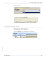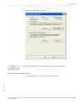
1
FP OPC Server FP OPC Server User’s Manual Programmable Controller User’s Manual Panasonic Electric Works Europe AG ACGM0143V3EN 7/2013 Before beginning Liability and copyright for the hardware This manual and everything described in it are copyrighted. You may not copy this manual, in whole or part, without written consent of Panasonic Electric Works Europe AG (PEWEU). PEWEU pursues a policy of continuous improvement of the design and performance of its products. Therefore we reserve the right to change the manual/product without notice. In no event will PEWEU be liable for direct, special, incidental, or consequential damage resulting from any defect in the product or its documentation, even if advised of the possibility of such damages. We invite your comments on this manual. Please e-mail us at: [email protected]. Please direct support matters and technical questions to your local Panasonic representative. Limited warranty If physical defects caused by distribution are found, PEWEU will replace/repair the product free of charge. Exceptions include: When physical defects are due to different usage/treatment of the product other than described in the manual. When physical defects are due to defective equipment other than the distributed product. When physical defects are due to modifications/repairs by someone other than PEWEU. When physical defects are due to natural disasters. Important symbols One or more of the following symbols may be used in this documentation: DANGER Indicates a hazardous situation which, if not avoided, will result in death or serious injury. WARNING Indicates a hazardous situation which, if not avoided, could result in serious or moderate injury. CAUTION Indicates a hazardous situation which, if not avoided, could result in minor or moderate injury. NOTICE Indicates a property damage message Note Example Procedure Reference Contains additional information or special remarks Contains an illustrative example of the previous text section. Indicates that a step-by-step procedure follows. Indicates where you can find additional information on the subject at hand. Table of contents Table of contents 1. Overview...................................................................................................... 9 1.1 Introduction to the Panasonic FP OPC Server .................................................................... 9 1.2 OPC and Its Underlying Technology ................................................................................... 9 1.3 Features of the FP OPC Server......................................................................................... 13 1.3.1 Connectivity ............................................................................................................ 13 1.3.2 Interruption Tolerance............................................................................................. 14 1.3.3 Communication Driver Test and Protocol Adaptation ............................................. 15 1.3.4 User Interface ......................................................................................................... 15 1.3.5 Namespaces ........................................................................................................... 15 1.3.6 Basic Software ........................................................................................................ 17 1.3.7 Online Changes ...................................................................................................... 17 1.4 Hardware and Software Requirements.............................................................................. 18 2. First Steps Using the FP OPC Server ..................................................... 19 1.5 Install the FP OPC Server ................................................................................................. 19 1.6 Start/Stop the FP OPC Server Application ........................................................................ 20 1.6.1 Start the FP OPC Server Application...................................................................... 20 1.6.2 Stop the FP OPC Server Application ...................................................................... 22 1.7 Channels............................................................................................................................ 23 FP OPC Server.docx 1.7.1 Add a New Channel ................................................................................................ 23 1.7.2 Update an Existing Channel ................................................................................... 25 1.8 Element Structure .............................................................................................................. 26 1.9 Devices .............................................................................................................................. 27 1.9.1 Add a New Device .................................................................................................. 27 FP OPC Server 5 Table of contents 1.10 Tag Groups ........................................................................................................................28 1.10.1 Add a New Tag Group.............................................................................................28 1.11 Tags ...................................................................................................................................29 1.11.1 Add a New Tag........................................................................................................30 1.11.2 Update an Existing Tag ...........................................................................................31 1.12 Server Operation ................................................................................................................32 1.12.1 Start the Server .......................................................................................................33 1.12.2 Stop the Server .......................................................................................................34 1.13 Transferring Project Information .........................................................................................35 1.13.1 Open/Save Project ..................................................................................................35 1.13.2 Import/Export Tag Data ...........................................................................................37 3. Graphical User Interface (GUI) ................................................................. 41 1.14 Configure the Working Area ...............................................................................................41 1.15 Menu Names and Commands ............................................................................................43 1.15.1 File Menu.................................................................................................................44 1.15.2 Edit menu ................................................................................................................44 1.15.3 View Menu...............................................................................................................44 1.15.4 Server Menu ............................................................................................................45 1.15.5 Tools Menu..............................................................................................................45 1.15.6 Help Menu ...............................................................................................................45 1.16 Panes .................................................................................................................................46 1.16.2 Tag Pane .................................................................................................................46 1.16.3 System Log Pane ....................................................................................................48 1.16.4 Server Status Pane .................................................................................................49 1.16.5 Help Pane................................................................................................................51 6 FP OPC Server FP OPC Server.docx 1.16.1 Navigator Pane........................................................................................................46 Table of contents 1.17 Toolbars ............................................................................................................................. 51 1.18 Wizard................................................................................................................................ 51 1.18.1 New Channel Wizard .............................................................................................. 52 1.18.2 New Device Wizard ................................................................................................ 53 1.18.3 New Tag Group Wizard .......................................................................................... 53 1.18.4 New Tag Wizard ..................................................................................................... 54 1.19 Project Information Input/Output ........................................................................................ 54 1.20 Communication Settings Dialog......................................................................................... 55 1.20.1 Serial Communication Settings............................................................................... 55 1.20.2 Modem Communication Settings ............................................................................ 57 1.20.3 Ethernet Communication Settings .......................................................................... 58 1.20.4 Ethernet (Local) Communication Settings .............................................................. 60 1.20.5 USB Communication Settings ................................................................................ 63 1.21 System Tray....................................................................................................................... 63 4. Namespaces.............................................................................................. 64 1.22 Introduction to Namespaces .............................................................................................. 64 1.23 Static, Manually Defined Namespace ................................................................................ 65 1.24 System Status Namespace ............................................................................................... 66 1.25 MEWTOCOL OPC Server Compatibility Namespace ....................................................... 66 5. Appendix ................................................................................................... 69 FP OPC Server.docx 1.26 Panasonic Addresses ........................................................................................................ 69 1.26.1 Special Internal Relays ........................................................................................... 69 1.26.2 Special Internal Data Registers .............................................................................. 69 1.27 Panasonic Data Types....................................................................................................... 70 FP OPC Server 7 Table of contents 1.28 Panasonic FP PLC Network Types ....................................................................................73 1.28.1 Serial Network .........................................................................................................73 1.28.2 Ethernet Network.....................................................................................................74 1.29 DCOM Configuration ..........................................................................................................75 1.30 Abbreviations......................................................................................................................82 Index ............................................................................................................... 85 FP OPC Server.docx Record of changes 8 FP OPC Server Chapter 1 Overview 1.1 Introduction to the Panasonic FP OPC Server The Panasonic FP OPC Server is a 32-bit Windows application with a modern user interface. It realizes the server end in the standard client/server model and incorporates the OPC DA standard. It allows you to share information between our proprietary devices (Panasonic FP Series PLCs) and any other device or application that supports the OPC DA standard. OPC DA technology succeeds Microsoft's Dynamic Data Exchange (DDE) technology in the demanding industrial environment. 1.2 OPC and Its Underlying Technology OPC (OLE (Object Linking and Embedding) for Process Control) is the successor of DDE technology. According to the OPC Foundation, “OPC is open connectivity in industrial automation and the enterprise systems that support industry. Interoperability is assured through the creation and maintenance of open standards specifications. There are currently seven standards specifications completed or in development (“What is OPC?”; www.opcfoundation.org http://www.opcfoundation.org)”. OPC is based on a series of approved standards and technologies of the FP OPC Server.docx consumer computer world. It was originally based on OLE COM (Component Object Model) and DCOM (Distributed Component Object Model), which provide the framework. Microsoft even added OPC standard to the OLE specification. OPC interface applications are built once and used several FP OPC Server 9 Overview times, thus are approved and under constant quality control. With OPC, data can be exchanged efficiently using a standardized interface, hence vendors do not have to implement their own communication drivers. Therefore it allows vendors to reduce implementation costs and save time, thus reducing the project cycle time. OPC Foundation The OPC Foundation defines itself as being "dedicated to ensuring interoperability in automation by creating and maintaining open specifications that standardize the communication of acquired process data, alarm and event records, historical data, and batch data to multi-vendor enterprise systems and between production devices. Production devices include sensors, instruments, PLCs, RTUs, DCSs, HMIs, historians, trending subsystems, alarm subsystems, and more as used in the process industry, manufacturing, and in acquiring and transporting oil, gas, and minerals (OPC Foundation; “What is the OPC Foundation?”; www.opcfoundation.org http://www.opcfoundation.org)”. The OPC Foundation is a cooperation of automation control product vendors and Microsoft. As of 2006, the foundation had about 300 members worldwide. The main standard, with which it all began, is the OPC DA (Data Access) specification. Compliance tests are provided to the members to test OPC conformity. COM The COM (Component Object Model) interface defines the externally visible binary structure of a COM object. The COM object is hereby the implementation of this model and can be based on several interfaces which define access to the object. It offers runtime access to the incorporated counting is implemented to manage the object's life cycle. Interactions between components are based on method-accesses defined in interfaces. COM applications are restricted to run locally on single computers only. 10 FP OPC Server FP OPC Server.docx interfaces of a COM object and interprocess communication. Reference Overview DCOM Upon inception, DCOM (Distributed Component Object Model) faced two major challenges: program-based processing of information, which led to information being represented differently backwards compatibility to existing COM and DDE applications OLE is based directly on DCOM. The DCOM interface allows COM applications to be distributed on several computers, providing a single security concept. DCOM applications are restricted by not: running over firewalls being platform independent (only Microsoft operating systems are FP OPC Server.docx supported) FP OPC Server 11 Overview OPC Data Access (DA) Version 1 of the OPC DA (Data Access) standard was released in 1996. Today version 3.0 is available. A task force within the OPC Foundation http://www.opcfoundation.org maintains and revises the OPC DA specification. The specification shows and describes how to construct client and server applications and allows vendors to quickly develop their own applications. It defines object hierarchy consisting of several OPC server objects, which in turn can consist of several OPC group objects. The group objects themselves can be composed of OPC item objects. OPC items correspond to process values and represent connections to data sources. The COM interface incorporated in the server offers the client two object types: group and item. A server object is automatically created after the client connects to the server. Associated with each item is a time stamp, its quality and the value of the item as a VARIANT type. The item tags--tag, node FP OPC Server.docx or property objects--have to be realized on the server side. 12 FP OPC Server Overview The node objects can contain either other node objects or leaf objects. Node objects are implemented as channel, device or tag group elements within the FP OPC Server. Tag objects, which are implemented as tag elements, represent the leaf objects in the object tree. The OPC client connected to the OPC server is responsible for the type of information it retrieves. It has to define the group structure, the poll rate and the read type, i.e. asynchronous or synchronous data retrieval. Using synchronous data retrieval, the client has to wait until the read operation is finished; using asynchronous data retrieval, on the other hand, allows the client to be informed immediately when data changes. 1.3 Features of the FP OPC Server The Panasonic FP OPC Server is a OutProc Server, thus the server application is started from an autarkic executable file. The server allows high-performance data transfer between applications that support the OPC DA standard and Panasonic FP Series PLCs. FP OPC Server.docx The following features are provided: 1.3.1 Connectivity The server provides “two-sided” connectivity: one side provides access to applications that support OPC DA; the other side provides access to FP Series FP OPC Server 13 Overview PLCs. In order to enable the user to perform functional tests, a simulation mode is implemented. This mode allows you to design the application without any PLC being connected to the computer. OPC Connectivity The server complies to the following OPC DA client/server technologies: OPC DA 1.0a OPC DA 2.05a OPC DA 3.0 Data can be exchanged between client and server in asynchronous, synchronous and refresh mode. Device Connectivity A standardized interface allows you to: monitor data from Panasonic FP PLCs synchronize data access and data writing use various communication types PLCs can be accessed via serial port (see p. 73), modem (see p. 57) and Ethernet (see p. 74). The server offers modem support to connect to remote stations via dial-up phone calls. Specify the communication mode at the communication channel level when you configure the application. Setting up the communication channel to use the modem means that dialing and connecting to the remote device is fully transparent to the OPC client application. Modem connections and direct 1.3.2 Interruption Tolerance In case a connected device stops responding, for instance because of a line interruption, the optimized communication is carried on for the still connected devices. Thus, the communication breakdown does not influence the time-out or response behavior of the devices which are still online. If the 14 FP OPC Server FP OPC Server.docx serial communication work similarly. Overview device starts being responsive again, the data transfer from / to the previously disconnected PLC is reinitialized and carried out normally. 1.3.3 Communication Driver Test and Protocol Adaptation If the server or application created with the server should be tested, the user can use a simulation driver to simulate reading and writing from and to virtual devices. To test MEWTOCOL protocol communication, the channel settings made by the user can be tested directly in the server application. Furthermore, the user can influence the type of protocol (use of RD commands instead of MD commands) to be used to prevent interdependencies with other applications using the MEWTOCOL protocol, for instance. For detailed information, please refer to the Options dialog of the Tools menu in the online help. 1.3.4 User Interface A modern, intuitive user interface (see p. 41) allows you to configure the server. While creating the application, sophisticated user assistance is available at any time. Various hints and error notifications help you configure the server. Online documentation is omnipresent to clarify the server configuration application. You are warned of possible faulty settings or changes while the server is running. Wizard dialogs assist you in creating and altering elements. The server allows you to change the display of the main window. The server can appear minimized as an icon in the system tray or maximized on the desktop. If started by an OPC client, the server is automatically started minimized in the tray icon, but can be brought to the foreground by simply FP OPC Server.docx double clicking the icon in the system tray (see p. 63). 1.3.5 Namespaces The OPC client browse able namespace provided by the server represents a description of all process values an OPC client can query from. It can be FP OPC Server 15 Overview distinguished between three different types of namespace elements. For detailed information, please refer to Namespaces (see p. 64). Static, Manual Namespace The manual, "static" namespace is specified in the configuration user interface of the server. The user who administrates the server, creates channels, devices, tag groups and tags. The user specifies the settings of the communication lines, the PLC and the data sources to be provided to the client. For detailed information, please refer to Static, Manually Defined Namespace (see p. 65). System Status Namespace This namespace contains system tags, which are used to provide status feedback on the server running. The client simply creates items of these tags and thereby retrieves the server status directly in the client application. The system status namespace shows the system date, system time, uptime, project path, number of tags, number of tags active in the clients and the number of clients connected. For detailed information, please refer to System Status Namespace (see p. 66). MEWTOCOL OPC Server Compatibility Namespace A MEWTOCOL OPC Server (the predecessor of this server) compatibility namespace is also provided. The user configures the communication settings, which are common for the communication lines (serial (see p. 55), modem (see p. 57) or Ethernet (see p. 58)). To use this namespace, the OPC client has to create the items such that they follow a certain syntax. The item path For syntax regulations and restrictions, please refer to MEWTOCOL OPC Server compatibility namespace (see p. 66). 16 FP OPC Server FP OPC Server.docx can be adapted to the specific needs. Overview 1.3.6 Basic Software The FP OPC Server is also available as Basic Software, which can be installed without a license number. After using the Basic Software for 120 minutes, you will be asked to save your project and all connections to the server are terminated. Watch the title bar to see how many minutes are left. You must confirm the message box displayed before you can restart the server. This message box is also displayed if the connection is closed before the time has expired. FP OPC Server.docx Please contact your local Panasonic distributor for the unlimited version. 1.3.7 Online Changes During online sessions, i.e. when OPC clients are connected to the FP OPC Server, you can make comprehensive changes to the currently opened project. You can add new elements such as channels, devices, tag groups or FP OPC Server 17 Overview tag elements (see p. 46) to the project. You can apply all kinds of changes, except deleting and renaming, to all elements. Note You can only delete and rename elements which are not currently being used by the client. 1.4 Hardware and Software Requirements Hardware Item Required Hard disk space 20MB or more CPU grade 300MHz or more Lowest capacity memory 128MB or more Available display resolution 1024 *768 or more Microsoft Windows XP SP3 Microsoft Windows Vista Operating Systems Microsoft Windows 7 Microsoft Windows 8 SP2 FP OPC Server.docx Microsoft Windows 2003 Server 18 FP OPC Server Chapter 2 First Steps Using the FP OPC Server 2.1 Install the FP OPC Server Before you begin the installation, unzip “SetupFPOPCServerxx.zip” and save it on your hard drive. Procedure 1. Double-click “SetupFPOPCServerxx.exe” to run the installer 2. Select [Next] 3. Read and accept the "License Agreement" 4. Select [Next] Enter your customer information and serial number (for the unlimited version only). The Basic version (see Basic Software in the online help) runs without serial number. 5. Select [Next] The following dialog appears and allows you to review the path you FP OPC Server.docx entered. 6. Select [Browse] to select the installation directory 7. Select [Next] FP OPC Server 19 First Steps Using the FP OPC Server The following dialog appears. 8. Specify the location of the program icons in the start menu 9. Select [Next] The dialog "Start Copying Files" appears so you can review your settings. 10. If the settings are OK, select [Next] to install the software 11. Select whether to restart your PC and then [Finish] to finish the installation The Panasonic FP OPC Server is now installed on your system. Note Start the FP OPC Server at least once to register the application in the windows system. 2.2 Start/Stop the FP OPC Server Application The OPC server can start in two modes: manually automatically, when an OPC client application tries to connect to the server. 20 FP OPC Server FP OPC Server.docx 2.2.1 Start the FP OPC Server Application First Steps Using the FP OPC Server Procedure Manual Start 1. Double-click the FP OPC Server icon The configuration user interface with an empty project is started. Automatic Start 1. Start the OPC client application Here the Softing Demo Client is started. 2. Browse the available server list, select FP OPC Server and connect to the server FP OPC Server.docx Here by double-clicking the icon. Now the OPC server is started automatically and the server icon is displayed in the system tray (see p. 63). FP OPC Server 21 First Steps Using the FP OPC Server The default project file (specified under Tools Options) is automatically loaded, the OPC subsystem is started and the client is connected to the server. If no default project has been specified, the most recently used project is loaded. Note If the OPC server application is started manually but the OPC subsystem has not been started, a new client connect starts the OPC subsystem and connects to this server instance. 2.2.2 Stop the FP OPC Server Application The OPC server application also stops in two ways: manually, e.g. by user intervention automatically, after the last OPC client application terminates the connection to the OPC server. Procedure Manual Stop Alternatively, click the close button of the application window. 22 FP OPC Server FP OPC Server.docx 1. Select "Exit" in the File menu or tray icon menu First Steps Using the FP OPC Server Automatic Stop The OPC server sutomatically stops when all clients have disconnected. Note The OPC server application is only terminated automatically if the configuration window is minimized to the system tray (see p. 63). 2.3 Channels A channel represents a means of communication. The following means of communication are possible: Serial communication (see p. 73) (RS232) Modem (see p. 57) Ethernet (see p. 74) USB (see p. 63) Please also refer to: Channel element in the online help New Channel Wizard (see p. 52) 2.3.1 Add a New Channel There are four ways to add a new channel element: FP OPC Server.docx 1. Double-click the dummy element FP OPC Server 23 First Steps Using the FP OPC Server 2. Click a toolbar icon 3. Select menu Edit New Channel 4. Select New Channel from the navigator pane's (see p. 46) pop-up menu. In all cases the wizard (see p. 52) starts. Now create the new channel. Procedure FP OPC Server.docx 1. Specify a name for the new channel 24 FP OPC Server First Steps Using the FP OPC Server 2. Select the driver For further information, refer to driver selection. 3. Fill in the communication settings by clicking [Settings...] The communication settings (see p. 55) dialog will appear. 2.3.2 Update an Existing Channel To update and existing channel element: double-click the channel element, or select Properties from the toolbar or pop-up menu. FP OPC Server.docx FP OPC Server 25 First Steps Using the FP OPC Server Select "Properties" from the toolbar. Select "Properties" from the pop-up menu. 2.4 Element Structure The FP OPC Server allows the creation of a clearly membered hierarchical element structure that fits the nature of the application. The hierarchy consists of several layers: On the first layer, multiple communication channels specify the mean communication. The channels comprise multiple devices to specify the PLC and its station number. Devices can contain multiple tag groups to segregate tag data on a group-by-group basis. Devices or tag groups themselves contain the tag data (see p. 46). A state-of-the-art import/export mechanism allow you to save, exchange or edit the data in the XML file format. Exchanging data can also be done using a CSV file. For further information, please refer to Import/Export Tag FP OPC Server.docx Information (see p. 54). 26 FP OPC Server First Steps Using the FP OPC Server 2.5 Devices A device represents a hardware device, a Panasonic FP series PLC, connected to the OPC server. The data sources provided by the server application in the namespaces (see p. 64) are situated on these devices. Data sources are hereby relay or register addresses (see p. 69), which can be accessed by the OPC server. Please also refer to: Device element in the online help New Device Wizard (see p. 53) 2.5.1 Add a New Device Procedure 1. Open the wizard (see p. 53) to create a new device element in one of the four ways described in "Add a New Channel (see p. 52)" Here the dummy item is used to create a new device. The wizard opens. FP OPC Server.docx 2. Specify a name for the new device. FP OPC Server 27 First Steps Using the FP OPC Server 3. To test the communication settings specified for the "Channel (see p. 23)", select [Test Communication] To update an existing device, please refer to the procedure of update an existing channel (see p. 25). 2.6 Tag Groups A tag group represents a structural element for grouping tag elements according to your application's needs. For instance, a group "Temperature" and "Liquid Level" can be created in the same device to distinguish between data sources related to temperature and those related to liquid levels. Additionally a tag group can be used to assign a certain time stamp to all tags included in the tag group. The time stamp can be specified by a DATE_AND_TIME variable in the PLC project. Please also refer to: New tag group wizard (see p. 53) 2.6.1 Add a New Tag Group 1. Open the wizard (see p. 53) to create a new tag group element in one of the four ways described in "Add a New Channel (see p. 52)" 28 FP OPC Server FP OPC Server.docx Procedure First Steps Using the FP OPC Server Here the pop-up menu is used to create the new tag group. The wizard opens. 2. Specify the name of the tag group element To update an existing tag group, please refer to the procedure of update an existing channel (see p. 25). 2.7 Tags A tag represents a single PLC variable (address). FP OPC Server.docx Please also refer to: FP OPC Server Tag pane (see p. 46) New Tag Wizard (see p. 54) 29 First Steps Using the FP OPC Server 2.7.1 Add a New Tag Procedure 1. Create a tag as described in "Add a New Channel (see p. 23)" section Here, the dummy item is used to create the new tag. 2. Double-click to add a new tag The wizard opens. 3. Specify the name, correct address, data type, description and the access type of the tag element 4. Select [Insert] to add the element directly to the list without closing the dialog Repeat selecting [Insert] to create a series of tag elements that count up tag names and addresses. when you have finished adding all elements FP OPC Server.docx 5. Select 30 FP OPC Server First Steps Using the FP OPC Server Example An example namespace. 2.7.2 Update an Existing Tag You can update an existing tag in several ways. For example, simply click in the field which should be changed, e.g. to update a name. Change multiple elements by selecting the desired elements and typing or selecting the new value. In this case, 3 elements were selected and their FP OPC Server.docx access rights changed to "read only". FP OPC Server 31 First Steps Using the FP OPC Server You can also change the tag's properties by double-clicking the tag to activate the wizard. Note You can only update values for individual elements when you use the wizard. 2.8 Server Operation In order to accept connections for an OPC client application, you must start the server's OPC subsystem by clicking . After the server is started, Note If the OPC server application is started manually but the OPC subsystem has not been started, a new client connect starts the OPC subsystem and connects to this server instance. 32 FP OPC Server FP OPC Server.docx clients can connect to the server. First Steps Using the FP OPC Server 2.8.1 Start the Server You will be notified when the server has been started successfully by: a log message (see p. 48) in the system log pane and an incrementing "Up Time (see p. 49)" value in the server status pane FP OPC Server.docx (see p. 49). FP OPC Server 33 First Steps Using the FP OPC Server You can also see that a client is connected (here the Softing Demo Client) in the system log and server status panes. 2.8.2 Stop the Server To stop the OPC subsystem, press All connections to OPC clients are terminated. Now the demo client has been disconnected. A log message informs you that 34 FP OPC Server FP OPC Server.docx Note . First Steps Using the FP OPC Server the OPC client has been disconnected and that the server has stopped. 2.9 Transferring Project Information You can save project data in XML or CSV format and exchange tag data between various OPC servers, e.g. Kepware or Beijers. You can also import global variables from Control FPWIN Pro in CSV format. 2.9.1 Open/Save Project Procedure Open Project from the toolbar FP OPC Server.docx 1. Select File Open or FP OPC Server 35 First Steps Using the FP OPC Server In the file open dialog all supported file formats (*.pos, *.xml) are displayed. 2. Select the desired file and click [Open] Alternatively, select a file from the recently opened file list. Note If no default project is specified in the options dialog, the most recently used project is automatically loaded when the client application starts the OPC FP OPC Server.docx server. 36 FP OPC Server First Steps Using the FP OPC Server Save Project 1. Select File Save or Save As… or of the toolbar The file save dialog opens: 2. Specify the project file name and file type (binary (*.pos) or XML (*.xml) format) 3. Select [Save] 2.9.2 Import/Export Tag Data In order to exchange, import, export or edit tag data, an export/import mechanism is available. Procedure Import tag data FP OPC Server.docx 1. Select the device or tag group element for which you want to import data FP OPC Server 37 First Steps Using the FP OPC Server 2. Select "Import" from the pop-up menu, the File menu or the navigator's toolbar 3. In the "File Open" dialog, select the XML or CSV file you want to import According to the import settings under Tools Options, you can select whether: tags available in the import file but not in the project are added to the project tags not available in the import file but in the project are deleted from the Tags available in the import file and in the project will be updated. 38 FP OPC Server FP OPC Server.docx project: First Steps Using the FP OPC Server The data is imported into the selected device or tag group item. Import other file formats The OPC Server can import global variables exported from FPWIN Pro or tag data exported from OPC Servers (Panasonic FP OPC Server, Kepware OPC Server, Beijers OPC Server). The various file formats are displayed below. FPWIN Pro Kepware OPC Server FP OPC Server.docx Beijer OPC Server FP OPC Server 39 First Steps Using the FP OPC Server Export tag data 1. Select the device or tag group element you want to export 2. Select "Export " from the pop-up menu, the File menu or the navigator's toolbar 3. Specify the file name and type 4. Select where you wish to save the file 5. Select [Save] Now you can edit the file if desired, e.g. with a text editor: FP OPC Server.docx Example for tag data exported in XML format Example for tag data exported in CSV format 40 FP OPC Server Chapter 3 Graphical User Interface (GUI) 3.1 Configure the Working Area The FP OPC Server configuration user interface consists of various panes. All panes offer a pop-up menu and you can access most functions related to the panes with toolbar icons. For each item in the panes, context sensitive help can be displayed in the help pane (see p. 51). Tool tips assist the user in understanding the topics when the cursor passes over them. You can dock all panes except the tag pane (see p. 46) W. You can close unneeded panes to enlarge the working area. Use the view menu (see p. 44) to display the panes FP OPC Server.docx after they have been closed. FP OPC Server 41 Graphical User Interface (GUI) You can resize and move the entire application anywhere on the desktop. All user-defined layout settings, pane status and window position are saved upon closing and restored when the server is restarted. Q The navigator pane (see p. 46) shows the hierarchical structure of channel, device and tag group elements. Elements of these types can be created and changed in this pane. W The tag pane (see p. 46) is where tag elements are created or updated. E The system log pane (see p. 48) shows the latest log messages, such as server status messages, client connections or connection timeouts and informs the user about these events. R The server status pane (see p. 49) shows the server status information. FP OPC Server.docx The help pane (see p. 51) displays the online help. You can temporarily slide open the pane by moving the mouse over the icon. Click on the icon if you prefer the pane to stay visible. 42 FP OPC Server Graphical User Interface (GUI) Customize your working area You can move or dock all panes except the tag pane anywhere in the window. 3.2 Menu Names and Commands The menu bar contains 6 menu names shown above. Please refer to the online help for detailed information under the keyword of the respective FP OPC Server.docx menu name. FP OPC Server 43 Graphical User Interface (GUI) 3.2.1 File Menu The File menu offers access to all file and project operations. 3.2.2 Edit menu The Edit menu allows you to create new channels, devices, groups and tags as well as execute the standard Windows editing commands: cut, copy, paste, delete and select all. 3.2.3 View Menu Display the navigator (see p. 46), system log (see p. 48) and server status FP OPC Server.docx panes (see p. 49) via this menu if they are hidden. 44 FP OPC Server Graphical User Interface (GUI) Note Display the help pane via the help menu (see p. 45). Further information: Configure the working area (see p. 41) 3.2.4 Server Menu The Server menu contains commands to control the server and set global communication parameters. 3.2.5 Tools Menu The Tools menu offers commands to start configuration and option dialogs. 3.2.6 Help Menu The help menu contains commands to access the online documentation, which can displayed inside the application or as an external help window. FP OPC Server.docx See also help pane (see p. 51). FP OPC Server 45 Graphical User Interface (GUI) 3.3 Panes The FP OPC Server user interface contains 5 panes described as follows. 3.3.1 Navigator Pane The navigator pane shows channel, device and tag group elements in a hierarchical structure. A wizard (see p. 51) starts at each level to help you create new elements. To update existing elements, simply double-click the item; a wizard will appear in this case, too. You can directly access all commands available in this pane via the toolbar or pop-up menu. Drag&Drop allows you to conveniently move device elements and tag group elements. Note On each hierarchical level, the name of the element has to be unique! For instance, only one channel element can be named "Com1". For a detailed description of the navigator pane, please refer to the online help under the keyword "Navigator pane". 3.3.2 Tag Pane in a list structure. A wizard (see p. 54) is started to help you create new elements. To update existing elements, simply double-click the item to open the wizard. You can make direct changes to the tag elements in the list by placing the cursor in the list cell or selecting an item from the combo box lists. To ease handling of many items, multiple rows can be selected and changes applied to all selected elements. The list 46 FP OPC Server FP OPC Server.docx The tag pane shows the tag elements Graphical User Interface (GUI) shows all properties of the tag element in a clearly arranged manner. All commands available in this pane are directly accessible from the toolbar or pop-up menu. Column Column number Header Explanation Shows the status of the element: correct Q warning error Hint: check the tool tip for help on configuring the element correctly. W Name Shows the tag's name Each tag element that is child to the same parent must have a unique tag name, e.g. only one tag can be named "OutsideTemperature". E Address Shows the element's address (see p. 69) R Data Type Shows the element's data type (see p. 70) T Creation Time Displays the creation time and date Y Access Right Shows the access rights of the tag U Description Allows you to enter a description for the tag You can disable elements by deactivating this check box (multiple selection with <Ctrl> and/or <Shift>). Disabled elements are not visible inside the OPC client. FP OPC Server.docx I FP OPC Server 47 Graphical User Interface (GUI) Arrange elements in meaningful groups For example, you wish to group elements by their enabled or disabled state. Simply drag the column I header inside the field "Drag a column header …" O. You can also sort the list of tag items by simply clicking on the column header P. Note To deselect multiple selected rows, simply click into column Q, W or E. Only the currently selected row will remain selected. For a detailed description of the tag pane, please refer to the online help under the keyword "Tag pane". 3.3.3 System Log Pane The system log pane displays information, warnings and error event For example, information about server start and stop events, client connects and disconnects are data time-outs are displayed. While the server application is running, log information is written into a log file. The log file path can be changed under Tools Options. 48 FP OPC Server FP OPC Server.docx messages. Graphical User Interface (GUI) See also: Configure the working area (see p. 41). 3.3.4 Server Status Pane The server status pane shows actual status information about the server application. All commands available in this pane are directly accessible from the toolbar or pop-up menu. Note The status information can also be directly retrieved from inside the OPC client by using the System namespace (see p. 66). Server Time The server time indicates the actual date and time of the server hosting system. Up Time The Up Time property is available when the server is running and displays how long the server has been up in "xxd(ays) xxh(ours) xxm(inutes) FP OPC Server.docx xxs(econds)". Connected Clients The number of connected OPC clients is displayed. FP OPC Server 49 Graphical User Interface (GUI) Number of Tags "Number of Tags" shows the total number of tags created within all devices and tag groups. Note All tags including disabled elements are counted. Number of Active Items The number of tags actively monitored within any of the OPC clients (created as Items) is displayed. Note The total number of tag instances is counted; if one client monitors the same element twice or two clients monitor the same element, the property counts both elements. For a detailed description of the Server status pane, please refer to the online FP OPC Server.docx help under the keyword "Server status pane". 50 FP OPC Server Graphical User Interface (GUI) 3.3.5 Help Pane The help pane can be docked and reacts context-sensitively to the current mouse or cursor position. You can “pin” it open or have it slide open and closed by passing the cursor over it. See also: Help menu (see p. 45). 3.4 Toolbars Each of the panes (see p. 46) in the FP OPC Server's configuration user interface (see p. 41) contains a toolbar that allows you easy access to all commands available within the pane. For a detailed description of the toolbar functions, please refer to the online FP OPC Server.docx help under the keyword "Toolbars". 3.5 Wizard To simplify creating and modifying namespace elements (see p. 64), a FP OPC Server 51 Graphical User Interface (GUI) wizard-like configuration dialog has been implemented. The wizard is opened to help you create a new element when you have double-clicked a dummy element (see also dummy element of tag pane). You can likewise modify an existing element's properties by double-clicking on the element. The wizard also opens when you execute similar commands via the menu, pop-up menu or toolbar (see p. 51) icon. Enter text On the left side of the dialog text input fields, you must enter an element name, for example. If the text you have entered is wrong, the field turns red and a tool tip assists you with an error message. Buttons On the right side, the buttons, such as [OK], [Cancel] and - if available - the navigation buttons [Next] and [Previous] can be found. By pressing [Next], the next page (also accessible via a tab flag) is displayed. Help At the bottom of the dialog, the omnipresent, context-sensitive online help can be found embedded. By selecting another control, for instance the next edit field, the help automatically displays the corresponding help page. 3.5.1 New Channel Wizard When you create or modify a channel element, the wizard is started in "(new) channel mode". You can view or modify an existing element, or create a new element. The first page identifies the channel element. The channel's name is specified here. MEWNET driver, a third page allows to you to edit the communication settings. For detailed information, please refer to the online help under the keyword "New Channel Wizard". 52 FP OPC Server FP OPC Server.docx On the second page, you select the I/O driver. If you have selected the Graphical User Interface (GUI) 3.5.2 New Device Wizard When you create or modify a device element, the wizard is started in "(new) device mode". You can view or modify an existing element, or create a new element. The wizard shows the identification page of the device element. The device's name and station number are specified here. For detailed information, please refer to the online help under the keyword "New Device Wizard". 3.5.3 New Tag Group Wizard With the Tag Group Wizard, you can view or modify an existing tag group element, or create a new element. FP OPC Server.docx The wizard shows the identification page of the tag group element. For detailed information, please refer to the online help under the keyword "New Tag Group Wizard". FP OPC Server 53 Graphical User Interface (GUI) 3.5.4 New Tag Wizard When you create or modify a tag element (see p. 46), the wizard is started in "(new) tag mode". You can view or modify an existing element, or create a new element. The wizard shows the identification page of the tag element. The tag's name, address, data type, access type and enabled state is set here. For detailed information, please refer to the online help under the keyword "New Tag Wizard". 3.6 Project Information Input/Output Load/Save The Project To save a new project or change an existing project, data can be stored in a project file on the hard disk in *.pos or *.xml format. For further information on loading and saving project data, please refer to Open/Save Project (see p. 35). Tag group and tag elements can be exported to an XML (*.xml) or CSV (*.CSV) file. The CSV file is compatible with the GVL CSV export file of FPWIN Pro. Project data (tags) can also be exchanged with other OPC server providers. For further information, please refer to: Import/Export Tag data (see p. 37). 54 FP OPC Server FP OPC Server.docx Import/Export Tag Information Graphical User Interface (GUI) 3.7 Communication Settings Dialog You can set communication parameters if you are using the MEWNET driver or if you want to configure the MEWTOCOL compatibility namespace (see p. 66). The following communication types are provided: Serial Modem Ethernet USB 3.7.1 Serial Communication Settings If "C-Net (RS232)" is selected as the network type, the following dialog FP OPC Server.docx appears. FP OPC Server 55 Graphical User Interface (GUI) Note Parameter Description COM Port Select a COM port Baud Rate Depending on the PLC used, choose a baud rate between 1200 and 115200 for communication between PLC and PC. Default is 9600 bps. Data length Select either 7 bits or 8 bits. (Default: 8 bits) Stop Bit Select either 1 bit or 2 bits. (Default: 1 bit) Parity Select from None, Odd, and Even. (Default: Odd) Time-out Set the time allowed (0-60 sec.) for communication to be established with the PLC. (Default: 5 sec.) Parameter for automatic setting: Activate the check box for the matching condition you want to search for when the communication parameters differ from the PLC. (Default: all check boxes are activated.) If no check box is activated, FPWIN Pro will not automatically search for suitable communication parameters. If the check box for "Parameter for automatic setting" is not activated, FP OPC Server will not automatically search for suitable communication parameters. You can also connect to a PLC network. The settings to be made depend on the PLC type and kind of connection. The FP OPC Server automatically searches for the suitable parameters unless you have deactivated this FP OPC Server.docx feature. Please also refer to the corresponding hardware manuals. 56 FP OPC Server Graphical User Interface (GUI) 3.7.2 Modem Communication Settings FP OPC Server.docx If you select "MODEM" as the network type, the following dialog appears: FP OPC Server Parameter Description Default COM Port Select from COM1-COM5 via which the modem is COM1 connected. Dial mode Select the dial mode (pulse, tone or self-defined) Pulse used by the modem. Initial AT command A modem manufacturer database is available which lists many standard modem models with their initialization strings. Title Enter a title for the communication settings set. Telephone number Enter the telephone number to dial. [Connect] Click [Connect] to establish the connection. [Disconnect ] Click [Disconnect] to terminate a previously started connection. Baud Rate Depending on the modem used, choose a baud rate between 1200 and 115200 for communication between PLC and PC. ATV1E0S0= 1S2=43 9600bps 57 Graphical User Interface (GUI) Parameter Description Default Data length Select either 7 bits or 8 bits. 8bits Stop Bit Select either 1 bit or 2 bits. 1bit Parity Select from None, Odd or Even. Odd [Add Entry] Click [Add Entry] to save the connection in the entry. [Entry List] When clicking on [Entry List] you can select, modify or delete an entry made before. Time-out Set the time allowed (0-60s) for communication to be established with the PLC. Public Line Time-out Set the time allowed (0-60s) for communication to be established to the communication partner. 5s The FP OPC Server can communicate with a peripheral controller that is connected via modem. When the server communicates with a Panasonic PLC, a modem can be attached directly to the CPU (except for FP1 C14/C16). 3.7.3 Ethernet Communication Settings FP OPC Server.docx If "Ethernet" is selected as "Network type", the following dialog appears. Set the communication parameters using Ethernet according to your 58 FP OPC Server Graphical User Interface (GUI) Hardware. This connection is based on TCP/IP protocol. Ensure you are familiar with IP addresses, ET-LAN units and Ethernet before using this connection. Especially when using the ET-LAN unit, understand the "ET-LAN SYSTEM Technical Manual" fully, and use the same settings on your computer. Set or change the following parameters if necessary: Parameter Description Use ET-LAN unit Check the checkbox when you use the ET-LAN unit. Do not check the checkbox when using the Ethernet-RS232C converter, etc., for example. Title Enter a title up to 38 characters long. Computer: Destination: IP address Set automatically. If not displayed, set properties of TCP/IP from network setting in control panel. (The setting procedure differs depending on the operating system used. Please refer to the Manuals and Help of OS.) Port No. Specify a value between 1025 and 32767 in decimal format (default: 1025). The Port No. for the IP address must be a unique, i.e. it cannot be used twice on your computer. Station No. Specify a value between 1 and 64 in decimal format (default: 64). Specify a Station No. different from the destination Station No. (PLC) that follows. (If ET-LAN unit is not used, Station No. is ignored.) IP address Specify IP address of destination (PLC) to communicate with. Port No. Specify a value between 1 and 32767 in decimal format (default: 1025) different from above. Station No. Specify a value between 1 and 64 in decimal format (default: 1). Specify a Station No. different from the computer‟s Station No. above. (If ET-LAN unit is not used, Station No. is ignored.) Specify a value between 1 and 950 seconds (default: 10). Connection Time-out Specify a value between 1 and 180 seconds (default: 60). FP OPC Server.docx Communication Time-out FP OPC Server 59 Graphical User Interface (GUI) Descriptions of Buttons: [OK] Click [OK] to save the communication settings; the current settings are not entered into the Entry List. If you want to enter them into the Entry List, click [Add Entry] before clicking [OK]. [Initialize] To reset the current setting„s parameters to the initial settings, click [Initialize]. [Refer...] When another program (an PEW application) is communicating with the PLC via the Ethernet and you want to connect to the same PLC, click [Refer...]. Then you can connect to the PLC easily by selecting the task in the TCP/IP Run List. No complicated procedure is required. Refer to the other task‟s settings for details. [Entry List...] To reuse parameters registered in the Entry List, click [Entry List...] [Add Entry] To add the current setting parameters to the Entry List, click [Add Entry]. 3.7.4 Ethernet (Local) Communication Settings The "Ethernet (Local) Communication Settings" dialog is only available via Server Communication Settings and can be configured using the MEWTOCOL OPC Server Compatibility Namespace (see p. 66) only. Note You can only change the communication parameters for the OPC Server if the OPC subsystem has not been started (see Start/Stop the FP OPC Server FP OPC Server.docx Application (see p. 20)). 60 FP OPC Server Graphical User Interface (GUI) Set the communication parameters using Ethernet according to your Hardware. This connection is based on TCP/IP protocol. Ensure you are familiar with IP addresses, ET-LAN units and Ethernet before using this connection. Especially when using the ET-LAN unit, understand the "ET-LAN SYSTEM Technical Manual" fully, and use the same settings on your FP OPC Server.docx computer. FP OPC Server 61 Graphical User Interface (GUI) Set or change the following parameters if necessary: Parameter Computer: Description IP address Set automatically. If not displayed, set properties of TCP/IP from network setting in control panel. (The setting procedure differs depending on the operating system used. Please refer to the manuals and help of the OS.) Port No. Specify a value between 1025 and 32767 in decimal format (default: 1025). The Port No. for the IP address must be a unique, i.e. it cannot be used twice on your computer. Station No. Specify a value between 1 and 64 in decimal format (default: 64). Specify a Station No. different from the destination Station No. (PLC) that follows. (If ET-LAN unit is not used, Station No. is ignored.) Use LinkUnit Station Number Activated: only one entry for a destination is possible Deactivated: you get access to the destination entry list to re-use parameters already entered Destination: Use ET-LAN unit Check the checkbox when you use the ET-LAN unit. Do not check the checkbox when using the Ethernet-RS232C converter, etc., for example. IP address Specify IP address of destination (PLC) to communicate with. Port No. Specify a value between 1 and 32767 in decimal format (default: 1025) different from above. Station No. Specify a value between 1 and 64 in decimal format (default: 1). Specify a Station No. different from the computer‟s Station No. above. (If ET-LAN unit is not used, Station No. is ignored.) Communication Time-out Specify a value between 1 and 950 seconds (default: 10). Connection Time-out Specify a value between 1 and 180 seconds (default: 60). [OK] Save the communication settings. [Initialize] To reset the current setting„s parameters to the initial settings, click [Initialize]. If "Use LinkUnit Station Number" is deactiavated 62 [Add] Add a new entry to the entry list. [Change] Select a line and click [Change] to change the parameters of the selected entry. [Delete] Select a line and click [Delete] to delete the selected entry. FP OPC Server FP OPC Server.docx Descriptions of Buttons: Graphical User Interface (GUI) 3.7.5 USB Communication Settings If "USB" is selected as the network type, the following dialog appears. Using this setting you can configure transparent PLC communication via the USB port of a GT panel. Specify a time-out value between 1s and 60s (default 5s). 3.8 System Tray When the server application is started, a tray icon appears in the window's system tray. The icon offers easy access to the main server functions, such as starting and stopping the server and maximizing or exiting the application. In case of an automatic start, i.e. the OPC client starts the FP OPC Server, the OPC Server is minimized to the tray only. To maximize the Configuration User Interface, either double-click on the FP OPC Server tray icon or select FP OPC Server.docx "Minimize/Maximize to Tray" from the System Tray menu. FP OPC Server 63 Chapter 4 Namespaces 4.1 Introduction to Namespaces A namespace is a hierarchical tree structure of elements. Namespaces are set up within the server and can be browsed for with an OPC client application. Three different namespaces can be built within the server: FP OPC Server.docx 1. User-defined manual namespace (see p. 65) 2. System status namespace (see p. 66) 3. MEWTOCOL OPC Server compatibility namespace (see p. 66) that ensures backward compatibility with the previous MEWTOCOL OPC Server. FP OPC Server 64 Namespaces 4.2 Static, Manually Defined Namespace The static namespace has to be defined by the user in the FP OPC Server configuration user interface as described in the previous chapters (left hand image). The root elements in the tree are the channel elements, which embody the means of communication, i.e. the communication line. Server side Client side Each channel element can contain device elements, which represent the devices where the data sources are located. On the next level, tag group combine elements in a way that makes sense for the particular application. The leafs of the tree are the tag elements (see p. 46). These elements directly represent the data sources offered to the OPC client application. On the right, the namespace representation within the OPC client can be seen. Note You cannot use elements named COMXXNXX or ETHERNXXNXX (e.g. COM1N64) in accordance to the regulations of MEWTOCOL OPC Server FP OPC Server.docx Compatibility Namespace (see p. 66). FP OPC Server 65 Namespaces 4.3 System Status Namespace The system status namespace provides the client application with general feedback about the server. For a detailed description of the read only tags, please refer to the online help under the keyword "System Status Namespace". 4.4 MEWTOCOL OPC Server Compatibility Namespace The previous OPC server, the MEWTOCOL OPC Server, did not support the definition of a static namespace (see p. 65). The Tags are accessed by defining the access path according to a certain syntax. In order to be backward compatible, the FP OPC Server supports the MEWTOCOL OPC Server namespace. You must define the communication settings beforehand in the communication settings dialog (see p. 55) that You must specify the communication channel on the first layer: 66 FP OPC Server FP OPC Server.docx opens via Server Communication Settings. Namespaces COM (serial and modem) communication XX The first two placeholders should specify the communication port to be used. N Optional. For C-NET must be "N". XX Optional. The second two placeholders specify the PLC station number if the PLC is connected via C-NET. Ethernet communication Note For further information, please refer to Panasonic FP PLC Network Types (see p. FP OPC Server.docx 73). FP OPC Server 67 Namespaces The second layer represents the Tag layer directly. Here, the item corresponding to the data source is created according to the following syntax conventions: <[1][2][3][4]Address where: Optional Description Values Notes [1] Specifies a memory bank number b0to b15 If empty, no bank is specified. [2] Specifies the number of w1 (1 word) If empty, 1-word data numerical data words. w2 (double types are used. word) Specifies the number of s1 to s256 character data words. [3] [4] Note Specifies the Item as a real or BCD value. Real: f BCD: B If empty, the value is displayed as decimal Specifies double word. D If empty, 1-word data types are used. D overrides w1 specified in [2] In contrast to the MEWTOCOL OPC Server, modem connections can also be used via COMXXNXX nodes. This namespace can also be used to dynamically create item instances FP OPC Server.docx within the OPC client application. 68 FP OPC Server Chapter 5 Appendix 5.1 Panasonic Addresses Panasonic FP Series PLCs use addresses from which you can read data or to which you can write data. Both bit and word addresses are used. 5.1.1 Special Internal Relays Special internal relays turn on and off under special conditions. The on and off states are not output externally. Writing is not possible with the FP OPC Server, a programming tool or an instruction. Reference For further information on special internal relays, please refer to the hardware manual of your Panasonic PLC. 5.1.2 Special Internal Data Registers Special data registers are one word (16-bit) memory areas which store specific information. Writing is not possible with the FP OPC Server, a FP OPC Server.docx programming tool or an instruction. Reference FP OPC Server For further information on special data registers, please refer to the hardware manual of your Panasonic PLC. 69 Appendix 5.2 Panasonic Data Types Panasonic's FP OPC Server supports several data types described hereafter. Undefined - Undefined Data Type An undefined data type is selected per default. If this data type is not changed, the OPC Server automatically adopts the data type according to the address of the variable. Boolean - Boolean Data Type (1-bit) Variables of the data type BOOL are binary variables. They can either have the value 0 or 1, and are 1 bit long. Condition Meaning Explanation 0 FALSE The variable is switched off, i.e. it is not set. 1 TRUE The variable is switched on, i.e. it is set. Signed 16-bit Variable values of the data type Signed 16-bit are natural numbers without decimal places. Range: -32768–32767 Unsigned 16-bit Variable values of the data type Unsigned 16-bit are numerical numbers without decimal places. Signed 32-bit Variable values of the data type Signed 32-bit are natural numbers without decimal places. 70 FP OPC Server FP OPC Server.docx Range: 0–65535 Appendix Range: -2147483648–2147483647 Unsigned 32-bit Variable values of the data type Unsigned 32-bit are numerical numbers without decimal places. Range: 0–4294967295 Word 16-bit A variable of the data type Word 16-bit consists of 16 binary states. The switching states of 16 in/outputs can be combined in one word. Word 32-bit A variable of the data type Word 32-bit consists of 32 binary states. The switching states of 32 in/outputs can be combined in one double Word. Float 32-bit Variables of the data type Float 32-bit consist of real numbers or floating point constants and can include up to seven effective digits. The mantissa consists of 23 bits and the exponent of 8 bits (based on IEEE754). Range: -3.402823*E38 to -1.175494*E-38, 0.0, +1.175494*E-38 to FP OPC Server.docx +3.402823*E38. String - String Data Type (Variable Length) The data type STRING consists of a series of up to 255 ASCII characters. All FP OPC Server 71 Appendix ASCII characters are considered as characters. BCD 16-bit The BCD represents a code scheme for numbers that allows base-ten computer calculation instead of the more common base two. BCD manipulation preserves accuracy by reducing round-off errors. BCD encoding is performed by using a four-digit binary number to encode each digit of the base ten number. BCD Decimal 0000 0 0001 1 0010 2 0011 3 0100 4 0101 5 0110 6 0111 7 1000 8 1001 9 BCD 32-bit The encoding of the BCD 32-bit is similar to the BCD 16-bit (see p. 72) data type, but instead of being 16 bits long, the BCD 32-bit consists of 32 bits. Date Variable values of the data type Date are date literals. FP OPC Server.docx Range: 2001-01-01–2099-12-31 Date And Time Variable values of the data type Date And Time are date and time literals. 72 FP OPC Server Appendix Range: 2001-01-01-00:00:00– 2099-12-31-23:59:59 Time Of Day Variable values of the data type Time Of Day are time of day literals. Range: 00:00:00–23:59:59 5.3 Panasonic FP PLC Network Types A Panasonic FP Series PLC can be connected to the PC in various ways. The PLC can be connected using the serial port (see p. 73) or Ethernet (see p. 74). Reference For further information on the different network types and how to connect and to wire the PLC, please refer to the appropriate hardware manual. 5.3.1 Serial Network Direct connection FP OPC Server.docx The PLC is directly connected to the PC using the serial communication line. FP OPC Server 73 Appendix C-NET adapter connection A maximum of 99 PLCs (FP-Sigma PLCs) can be connected to a single PC. The access path is for example (using the MEWNET compatibility syntax): Note Node1: COM1N1 Node2: COM1N2 Node3: COM1N3 This version of the FP OPC Server does not support the MEWNET W/W2 remote access. 5.3.2 Ethernet Network PLCs can be connected to the PC via Ethernet. FP OPC Server.docx Each PLC is connected to a HUB or SWITCH 74 FP OPC Server Appendix The access path is for example (using the MEWNET compatibility syntax): Note Node1: ETHERN1 Node2: ETHERN2 Node3: ETHERN3 This version of the FP OPC Server does not support the MEWNET W/W2 remote access. 5.4 DCOM Configuration Starting with Windows XP Service Pack 2, Microsoft implemented a new FP OPC Server.docx security strategy. This step, amongst others, was needed to reduce XP's vulnerability to dangerous attacks from outside (e.g. the Internet). This was realized by shielding the computer from the network side and various other improvements. FP OPC Server 75 Appendix In order to access the OPC Server from a client not installed on the same machine, DCOM (see p. 11) communication has to be set up. You have to adapt two areas of the Windows XP operating system: the firewall (network shielding) settings the DCOM security settings The first step has already been done during the installation phase. After installing the FP OPC Server, you will find three new firewall rules: "DCOM Port 135 TCP", "OPC Enumeration Service" and "FP OPC Server 2". These rules enable the firewall to accept incoming requests to the FP OPC Server. DCOM enhancements The DCOM settings specify the limits and security constraints, such as launch and access permissions for the FP OPC Server. Launch permissions hereby specify the users who are allowed to start an application. Access permissions grant specified users access to the application. Procedure 1. Select Tools DCOM configuration You get access to the DCOM (see p. 11) security settings. 2. Within the tree, expand "Component Services" and "Computers" FP OPC Server.docx 3. From the pop-up menu of "My Computer", select "Properties" 76 FP OPC Server Appendix 4. Select the "COM Security" tab Note Perform the following five steps to adapt the permission configurations. Step 1: Edit access permission FP OPC Server.docx 1. Select [Edit Limits...] under "Access Permissions" FP OPC Server 77 Appendix The user named "ANONYMOUS LOGON" is mandatory for the OPC Enumeration function. 2. Activate both "Allow" check boxes, for "Local Access" and "Remote Access" 3. [OK] Step 2: Edit launch permission FP OPC Server.docx 1. Under "Launch and Activation Permissions", select [Edit Limits...] 78 FP OPC Server Appendix The user "Everyone" has to be adapted. 2. Activate all 4 "Allow" check boxes, for "Local Launch", "Remote Launch", "Local Activation" and "Remote Activation" 3. [OK] Note To reduce the access rights to a smaller group of users, select only the desired users from the list instead of the general user "Everyone". Step 3: Add a new user who can remotely access the OPC Server FP OPC Server.docx 1. Under "Access Permissions", select [Edit Default...] 2. Add a new user who can remotely access the OPC Server FP OPC Server 79 Appendix 3. Activate both "Allow" check boxes, for "Local Access" and "Remote Access" 4. Under "Launch and Activation Permissions", select [Edit Default...] 5. For th new user entry, select all 4 launch types. 6. [OK] to close the "My Computer Properties" dialog Step 4: Activate the interactive user 1. Under "My Computer", expand "DCOM Config" FP OPC Server.docx 2. Select "FP OPC Server 2" 80 FP OPC Server Appendix 3. From the pop-up menu, open the FP OPC Server properties 4. Select the "Identity" tab and activate the "Interactive user" who shall run the OPC Server 5. [OK] FP OPC Server.docx Step 5: Reboot your PC after changing the DCOM security settings FP OPC Server 81 Appendix 5.5 Abbreviations BCD Binary Coded Decimal BCD 16-bit (see p. 72) COM Component Object Model CSV Character Separated Values DA Data Access DCOM Distributed Component Object Model DDE Dynamic Data Exchange FP OPC Server.docx GVL Global Variable List (Control FPWIN Pro) OLE Object Linking and Embedding 82 FP OPC Server Appendix OPC OLE for Process Control OutProc An OutProc server realizes one of three characteristics of a standardized OPC server. If implemented as an OutProc server, the application is started by an OPC client from an autarkic executable file. The server application can reside on the local or a remote machine. PLC Programmable Logic Controller XML FP OPC Server.docx Extended Markup Language FP OPC Server 83 D Index DA.......................................................................... 84 A Data Types ............................................................ 70 Abbreviations ........................................................ 83 Date ....................................................................... 72 Add a New Channel .............................................. 23 Date And Time ...................................................... 73 Add a New Device ................................................ 27 DCOM .............................................................11, 84 Add a New Tag ..................................................... 30 DCOM Configuration ............................................. 76 Add a New Tag Group .......................................... 28 DDE ....................................................................... 84 Appendix ............................................................... 69 Device Connectivity ............................................... 13 B Devices .................................................................. 26 Basic Software ...................................................... 16 E BCD ...................................................................... 83 Edit menu .............................................................. 44 BCD 16-bit ............................................................ 72 Element Structure.................................................. 26 BCD 32-bit ............................................................ 72 Ethernet (Local) Communication Settings ............ 60 Before beginning..................................................... 1 Ethernet Communication Settings......................... 58 Boolean - Boolean Data Type (1-bit) .................... 70 Ethernet Network................................................... 75 C F Channels ............................................................... 23 Features of the FP OPC Server ............................ 13 COM................................................................ 10, 84 Features of the OPC Server .................................. 13 Communication Driver Test and Protocol Adaptation .......................................................................... 14 Communication Settings Dialog ........................... 55 FP OPC Server.docx Configure the Working Area ................................. 42 File Menu ............................................................... 44 First Steps Using the FP OPC Server ................... 19 Float 32-bit ............................................................ 71 Connected Clients ................................................ 49 G Connectivity .......................................................... 13 Graphical User Interface (GUI) ............................. 42 CSV....................................................................... 84 GVL ....................................................................... 84 FP OPC Server 85 H Number of Active Items ........................................ 49 Hardware and Software Requirements................. 17 Number of Tags .................................................... 49 Help Menu............................................................. 45 O Help Pane ............................................................. 51 OLE ...................................................................... 84 I Online Changes .................................................... 17 Import/Export Tag Data ........................................ 37 OPC ...................................................................... 84 Import/Export Tag Information .............................. 54 OPC and Its Underlying Technology ...................... 9 Important symbols................................................... 2 OPC Connectivity ................................................. 13 Install the FP OPC Server .................................... 19 OPC Data Access (DA) ........................................ 11 Interruption Tolerance ........................................... 14 OPC Foundation ................................................... 10 Introduction to Namespaces ................................. 64 Open/Save Project ............................................... 35 Introduction to the Panasonic FP OPC Server ....... 9 OutProc ................................................................ 84 L Overview................................................................. 9 Load/Save The Project ......................................... 54 P M Panasonic Addresses ........................................... 69 Menu Names and Commands .............................. 43 Panasonic Data Types ......................................... 70 Panasonic FP PLC Network Types ...................... 73 Namespace ....................................................... 66 Panes ................................................................... 46 Modem Communication Settings .......................... 57 PLC ....................................................................... 85 N Project Information Input/Output .......................... 54 Namespaces ................................................... 15, 64 R Navigator Pane ..................................................... 46 Record of Changes .............................................. 90 New Channel Wizard ............................................ 52 New Device Wizard............................................... 53 New Tag Group Wizard ........................................ 53 New Tag Wizard ................................................... 54 86 S Serial Communication Settings ............................ 55 Serial Network ...................................................... 74 Server Menu ......................................................... 45 FP OPC Server FP OPC Server.docx MEWTOCOL OPC Server Compatibility Index Server Operation .................................................. 32 U Server Status Pane............................................... 49 Undefined - Undefined Data Type......................... 70 Server Time .......................................................... 49 Unsigned 16-bit ..................................................... 70 Signed 16-bit......................................................... 70 Unsigned 32-bit ..................................................... 71 Signed 32-bit......................................................... 70 Up Time ................................................................. 49 Special Internal Data Registers ............................ 69 Update an Existing Channel .................................. 25 Special Internal Relays ......................................... 69 Update an Existing Tag ......................................... 31 Start the FP OPC Server Application ................... 20 USB Communication Settings ............................... 63 Start the Server..................................................... 33 User Interface ........................................................ 14 Start/Stop the FP OPC Server Application ........... 20 V Static, Manually Defined Namespace................... 65 View Menu ............................................................. 44 Stop the FP OPC Server Application.................... 22 W Stop the Server ..................................................... 34 Wizard ................................................................... 51 String - String Data Type (Variable Length) ......... 71 Word 16-bit ............................................................ 71 System Log Pane ................................................. 48 Word 32-bit ............................................................ 71 System Status Namespace .................................. 66 X System Tray.......................................................... 63 XML ....................................................................... 85 T Tag Groups ........................................................... 28 Tag Pane .............................................................. 46 Tags ...................................................................... 29 Time Of Day.......................................................... 73 FP OPC Server.docx Toolbars ................................................................ 51 Tools Menu ........................................................... 45 Transferring Project Information ........................... 35 FP OPC Server 87 Record of Changes Manual No. Date Description of Changes ACGM0143V1.0END Dez. 2006 First edition ACGM0143V1.1END Jan. 2007 Updated documentation: notes on removing the software. ACGM0143V1.2END Apr. 2007 The description of Ethernet (Local) communication has been moved to the section Communication Settings (see p. 55). ACGM0143V1.3END Mai 2007 Microsoft Windows Vista compatible ACGM0143V1.4EN Sept. 2007 MEWNET W/W2 connection removed ACGM0143V1.5EN Mai. 2008 New options are available under Tools Options Event Log Settings: Enable debug message logging Enable memory status message logging Jan. 2010 Update for release of FP OPC Server 2. See the section "New in this version" in the online help. Sept. 2010 Update for release of FP OPC Server 2.01. See the section "New in this version" in the online help. ACGM0143V2EN Oct. 2011 Update for release of FP OPC Server 2.02. See the section "New in this version" in the online help. ACGM0143V3EN July 2013 Update for release of FP OPC Server 2.021. See the section "New in this version" in the online help. Global Network North America Europe Asia Pacific China Japan Panasonic Electric Works Global Sales Companies Europe ffHeadquarters Panasonic Electric Works Europe AG ffAustria Panasonic Electric Works Austria GmbH ffBenelux Panasonic Industrial Devices Materials Europe GmbH Panasonic Electric Works Sales Western Europe B.V. Panasonic Electric Works Czech s.r.o. ffCzech Republic ffFrance ffGermany Panasonic Electric Works Sales Western Europe B.V. Panasonic Electric Works Europe AG ffHungary Panasonic Electric Works Europe AG ffIreland ffItaly Panasonic Electric Works UK Ltd. Panasonic Electric Works Italia s.r.l. ffNordic Countries Panasonic Electric Works Nordic AB ffPoland ffPortugal Panasonic Eco Solutions Nordic AB Panasonic Electric Works Polska sp. z o.o. Panasonic Electric Works España S.A. ffSpain Panasonic Electric Works España S.A. ffSwitzerland Panasonic Electric Works Schweiz AG ffUnited Kingdom Panasonic Electric Works UK Ltd. Rudolf-Diesel-Ring 2, 83607 Holzkirchen, Tel. +49 (0) 8024 648-0, Fax +49 (0) 8024 648-111, www.panasonic-electric-works.com Josef Madersperger Str. 2, 2362 Biedermannsdorf, Tel. +43 (0) 2236-26846, Fax +43 (0) 2236-46133, www.panasonic-electric-works.at Ennshafenstraße 30, 4470 Enns, Tel. +43 (0) 7223 883, Fax +43 (0) 7223 88333, www.panasonic-electronic-materials.com De Rijn 4, (Postbus 211), 5684 PJ Best, (5680 AE Best), Netherlands, Tel. +31 (0) 499 372727, Fax +31 (0) 499 372185, www.panasonic-electric-works.nl Organizační složka, Administrative centre PLATINIUM, Veveri 111, 616 00 Brno, Tel. (+420)541 217 001, Fax (+420)541 217 101, www.panasonic-electric-works.cz Succursale française, 10, rue des petits ruisseaux, 91371 Verrières le Buisson, Tél. +33 (0) 1 6013 5757, Fax +33 (0) 1 6013 5758, www.panasonic-electric-works.fr Rudolf-Diesel-Ring 2, 83607 Holzkirchen, Tel. +49 (0) 8024 648-0, Fax +49 (0) 8024 648-111 www.panasonic-electric-works.de Magyarországi Közvetlen Kereskedelmi Képviselet, 1117 Budapest, Neumann János u. 1., Tel. +36(0)1482 9258, Fax +36 (0) 1482 9259, www.panasonic-electric-works.hu Irish Branch Office, Dublin, Tel. +353 (0) 14600969, Fax +353 (0) 14601131, www.panasonic-electric-works.co.uk Via del Commercio 3-5 (Z.I. Ferlina), 37012 Bussolengo (VR), Tel. +39 (0) 456752711, Fax +39 (0) 456700444, www.panasonic-electric-works.it Filial Nordic, Knarrarnäsgatan 15, 16440 Kista, Sweden, Tel. +46 859476680, Fax +46 859476690, www.panasonic-electric-works.se Jungmansgatan 12, 21119 Malmö, Tel. +46 40697-7000, Fax +46 40697-7099, www.panasonic-fire-security.com ul. Wołoska 9A, 02-583 Warszawa, Tel. +48 (0) 22 338-11-33, Fax +48 (0) 22 338-12-00, www.panasonic-electric-works.pl Portuguese Branch Office, Avda Adelino Amaro da Costa 728 R/C J, 2750-277 Cascais, Tel. +351 214812520, Fax +351 214812529 Barajas Park, San Severo 20, 28042 Madrid, Tel. +34 913293875, Fax +34 913292976, www.panasonic-electric-works.es Grundstrasse 8, 6343 Rotkreuz, Tel. +41 (0) 417997050, Fax +41 (0) 417997055, www.panasonic-electric-works.ch Sunrise Parkway, Linford Wood, Milton Keynes, MK14 6 LF, Tel. +44(0) 1908 231555, +44(0) 1908 231599, www.panasonic-electric-works.co.uk North & South America ffUSA Panasonic Industrial Devices Sales Company of America 629 Central Avenue, New Providence, N.J. 07974, Tel. +1-908-464-3550, Fax +1-908-464-8513, www.pewa.panasonic.com Asia Pacific / China / Japan ffChina Panasonic Electric Works (China) Co., Ltd. ffHong Kong Panasonic Industrial Devices Automation Controls Sales (Hong Kong) Co., Ltd. Panasonic Corporation ffJapan ffSingapore Panasonic Industrial Devices Automation Controls Sales Asia Pacific Pte. Ltd. Level 2, Tower W3, The Tower Oriental Plaza, No. 2, East Chang An Ave., Dong Cheng District, Beijing 100738, Tel. +86-10-5925-5988, Fax +86-10-5925-5973 RM1205-9, 12/F, Tower 2, The Gateway, 25 Canton Road, Tsimshatsui, Kowloon, Hong Kong, Tel. +852-2956-3118, Fax +852-2956-0398 1048 Kadoma, Kadoma-shi, Osaka 571-8686, Japan, Tel. +81-6-6908-1050, Fax +81-6-6908-5781, www.panasonic.net 300 Beach Road, #16-01 The Concourse, Singapore 199555, Tel. +65-6390-3811, Fax +65-6390-3810 Copyright © 2013. All rights reserved. Specifications are subject to change without notice. Printed in Europe. ACGM0143V3EN 7/2013