1
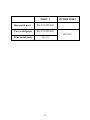
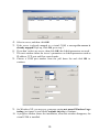
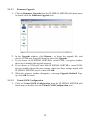
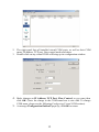
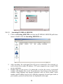
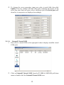
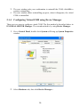
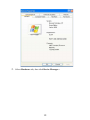
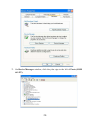
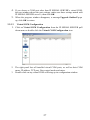
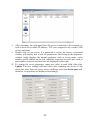
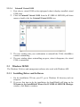
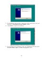
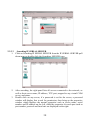
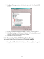
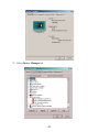
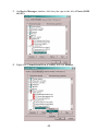
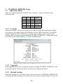
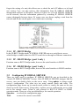
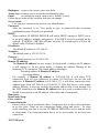
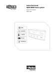
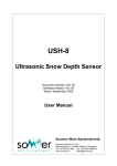
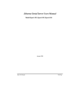
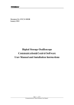
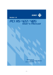
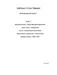
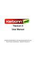
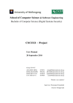
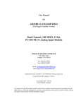
IP SERIAL DEVICE SERVER
( 1 / 2 / 4 serial port )
Installation guide
And
User manual
Version 1.0
1Introduction......................................................................................... 5
1.1Direct IP mode..............................................................................5
1.2Virtual COM mode.......................................................................5
1.3Paired mode..................................................................................6
1.4Heart beat..................................................................................... 6
2Driver installation and Configuration................................................. 7
2.1Windows 2000/XP....................................................................... 7
2.1.1Installing Driver and Software.............................................. 7
2.1.2Installing Virtual COM......................................................... 9
2.1.3Using IP SERIAL SERVER Manager.................................11
2.1.4Configuring Virtual COM using Device Manager ............. 16
2.1.5Uninstalling Virtual COM using Device Manager..............18
2.2Windows NT.............................................................................. 22
2.2.1Installing Driver and Software............................................ 22
2.2.2Installing Virtual COM....................................................... 23
2.2.3Using IP SERIAL SERVER Manager.................................25
2.3Windows 98/ME........................................................................ 30
2.3.1Installing Driver and Software............................................ 30
2.3.2Installing Virtual COM....................................................... 32
2.3.3Using IP SERIAL SERVER Manager.................................35
2.3.4Configuring Virtual COM Using Device Manager............. 40
2.3.5Uninstalling Virtual COM Using Device Manager.............42
3IP SERIAL SERVER Usage............................................................. 46
3.1Operation Mode..........................................................................46
3.1.1Console................................................................................46
3.1.2Upgrade............................................................................... 46
3.1.3Default Setting.....................................................................46
3.1.4IP - RS232 Bridge............................................................... 47
3.1.5IP - RS422 Bridge ( port 1 only )........................................ 47
3.1.6IP - RS485 Bridge ( port 1 only )........................................ 47
3.2Configuring IP SERIAL SERVER.............................................47
3.3Pin Assignment.......................................................................... 49
4Troubleshooting................................................................................ 49
PORT 1
One serial port
RS-232/422/485
Two serial ports
RS-232/422/485
OTHER PORT
RS-232
Four serial ports
RS-232
4
1
Introduction
The IP SERIAL SERVER provides the serial device server for Windows hosts to
control serial devices located virtually anywhere through a TCP/IP or UDP/IP Ethernet
connection. The IP SERIAL SERVER has the asynchronous serial port connection on
one side, and a 10/100 Mbps Ethernet connection on the other side. It connects
devices, such as CNC, weight scales, and scanners. Applications include
industrial/factory automation, automatic warehouse control, and hospital/laboratory
automation.
The IP SERIAL SERVER Windows driver is designed to control the IP SERIAL
SERVER Ethernet devices. The driver installs a virtual COM on windows which maps
the virtual COM port to the IP address of the IP SERIAL SERVER device across the
network, enabling the Windows applications to access remote serial devices over
Ethernet.
IP SERIAL SERVER can function as a server or client for both TCP and UDP
connection. The application scenarios are direct IP mode, virtual COM mode, and
paired mode. In direct IP and virtual COM modes, IP SERIAL SERVER should only
work as a server. When in the paired mode one IP SERIAL SERVER must set as a
client and the other must set as a server in both TCP and UDP connection. IP SERIAL
SERVER also provides a heartbeat connection for application or virtual COM to detect
whether IP SERIAL SERVER is still online.
1.1
Direct IP mode
1.2
Virtual COM mode
In direct IP connection, applications can communicate with IP SERIAL SERVER
using TCP/IP or UDP/IP socket connection. The raw data in the IP packet will be
transferred from and to IP SERIAL SERVER’ serial port.
In the virtual COM mode, the host connects to IP SERIAL SERVER through 10/100
Ethernet. The serial device is then connected to IP SERIAL SERVER.
Ethernet
Serial
IP SERIAL
DEVICE SERVER
IP101S
Serial Device
Applications work just as if the serial device is connected to host’s COM port, however
it is a virtual COM port that convert application’s data into IP packet. IP SERIAL
SERVER then converts the IP packet back to serial data. In this mode, IP SERIAL
SERVER must set to either TCP/server or UDP/server. The virtual COM driver is a
5
TCP or UDP client. A security feature is built in IP SERIAL SERVER. When IP
SERIAL SERVER works as a server it will allow incoming connection only when
remote IP address passes its IP address filtering. For more detail, please look at the
section, Configuring IP SERIAL SERVER.
1.3
Paired mode
Paired mode is also called serial tunneling. Two IP SERIAL SERVER are involved
and they must be set to a client and server pair. The remote IP address of the client site
must be the same as server’s IP address and IP address of the client site must pass
server’s address filtering. Applications do not actually use virtual COM port. They use
the regular COM port and host connects to IP SERIAL SERVER through a null
modem cable as shown below.
Serial
Ethernet
IP SERIAL DEVICE
IP101SSERVER
Serial
IP SERIAL
DEVICE SERVER
IP101S
Serial Device
The paired mode is a quick method to convert a serial connection into an Internet
connection without installing any other software on the host.
1.4
Heart beat
IP SERIAL SERVER provides a convenient way to reconnect TCP data connection, in
case of power failure on either client or server site. TCP port, 5300, is reserved for the
heartbeat connection. After a client, either virtual COM or IP SERIAL SERVER,
establishes a data connection to an IP SERIAL SERVER server, it will start the
heartbeat connection. When the heartbeat connection is established. The server will
send a signal to the client every 5 second. The client would timeout after 5 second if it
did not receive the signal and it will try to reconnect the TCP data connection every 5
seconds until the server is back online. Heart beat only works for the TCP connection,
not for UDP connection. When an application works on direct IP connection mode. It
can choose to work either with or without heartbeat connection.
6
2
Driver installation and Configuration
This chapter will explain how to install and configure virtual serial COM drivers on
Windows 98/ME/NT/2000/XP. With the virtual serial COM ports, you can control the
serial devices connecting to the IP SERIAL SERVER as it is connecting to your PC’s
COM ports.
2.1
Windows 2000/XP
The Windows 2000 driver and management software also work with Windows XP.
2.1.1
1.
2.
Installing Driver and Software
Put the installation CD into your PC, go to Windows 2000 directory and run
setup.exe.
If you are first time to do the installation, the Install Shield will bring up the
Welcome to the Install Shield Wizard for IP SERIAL SERVER Manager
window, click Next to continue.
3. The Install Shield will copy files to appropriate folder and all other work, and
finish that by Install Shield Wizard Complete window.
4. Click Finish to complete the installation.
7
5. If you already ran the installation before, the Install Shield will bring up the
Welcome Modify, repair, or remove the program window.
6. Choose an option to modify, repair or remove installed components, then
7.
click Next to continue.
When the Maintenance Complete window comes up, click Finish to
complete the maintenance.
8
2.1.2
Installing Virtual COM
1. Click on Start -> Programs -> IP SERIAL SERVER -> Install Virtual
COM.
2.
3.
The first window indicates installation program search IP SERIAL SERVER
servers connected to the network.
The next window lists all servers connected to the network, as well as their
server name, IP address, TCP port, flow control mode and if they are mapped
to any virtual COM.
9
4. Select a server, and then click OK.
5. If the server is already mapped to a virtual COM, a message the server is
already mapped! Pops up, click OK go to step 3.
6. If you don’t select any server, then click OK, the default parameters are used.
7.
8.
The next window shows the server’s parameters or default parameters such as
IP address, TCP port and flow control mode.
Choose a COM port number from the pull down list and click OK to
continue.
9. On Windows XP, you may see a message saying not passed Windows Logo
testing, just ignore it, and click Continue Anyway to continue.
10. A progress window shows the installation, when this window disappears, the
virtual COM is installed.
10
2.1.3
Using IP SERIAL SERVER Manager
IP SERIAL SERVER Manager includes the following utilities: Firmware Upgrade,
Virtual COM Configuration, Searching IP SERIAL SERVER, and Uninstall Virtual
COM. To start IP SERIAL SERVER Manager, click on Start -> Programs -> IP
SERIAL SERVER -> IP SERIAL SERVER Manager.
Switch between Virtual COM list and IP SERIAL SERVER server list Click the
Virtual COM Configuration icon,
The right panel lists all installed virtual COM ports from the last configuration. Click
the Searching SERVER icon; the right panel lists all servers connected to the network
from the last searching.
11
2.1.3.1
Firmware Upgrade
1. Click on Firmware Upgrade from the IP SERIAL SERVER pull down menu
or double click the Firmware Upgrade icon.
2. In the Upgrade window, click Browse... to locate the upgrade file, and
3.
4.
5.
2.1.3.2
choose a COM port from pull down list, then click Upgrade.
If you choose an IP SERIAL SERVER’s virtual COM, a progress window
shows up to indicate the upgrade progress.
If you choose a COM port other than IP SERIAL SERVER’s virtual COM,
the next window shows the port settings, make sure these settings match with
IP SERIAL SERVER server’s, then click OK.
When the progress window disappears, a message Upgrade finished! Pops
up, click OK to return.
Virtual COM Configuration
1. Click on Virtual COM Configuration from the IP SERIAL SERVER pull
down menu or double click the Virtual COM Configuration icon.
12
2.
3.
The right panel lists all installed virtual COM ports, as well as their COM
name, IP address, TCP port, flow control mode and status.
Double click on any virtual COM will bring up its configuration window.
4. Make changes on IP Address, TCP Port, Flow Control, as you want, then
5.
click OK. (Note: the change to the COM name here is not valid. To change
COM name, please see the following Configuring Virtual COM section).
A message Configuration finished! pops up, click OK to return.
13
2.1.3.3
Searching IP SERIAL SERVER
1. Click on Searching SERVER icon from the IP SERIAL SERVER pull down
menu or double click the Searching SERVER icon.
2.
3.
After searching, the right panel lists all servers connected to the network, as
well as their server name, IP address, TCP port, mapped to any virtual COM
or not, and status.
Double click on any server, if a password is set for the server, a password
window will display first to ask for permission, then bring up the properties
window which displays the mutual properties such as server name, serial
number and IP address on the left, while the properties for each port such as
port number, protocol and baud rate are displayed on the right.
14
4. To change the server properties, input new value in each field, then click
Update. The new settings will take effect after restarting the device. If the
server has more than one ports, select a different port from Serial port pull
down list, its properties are displayed accordingly.
2.1.3.4
Uninstall Virtual COM
1. First select a virtual COM on the right panel when it displays installed virtual
COM ports.
2. Click on Uninstall Virtual COM from the IP SERIAL SERVER pull down
menu or double click the Uninstall Virtual COM icon.
15
3. The next window asks your confirmation to uninstall the COM, click OK to
4.
2.1.4
continue uninstalling.
The next window shows uninstalling progress, when it disappears, the virtual
COM is uninstalled.
Configuring Virtual COM using Device Manager
There are two ways to configure virtual COM. The first method is described above in
IP SERIAL SERVER Manager. The second method is by using Device Manager.
1. Go to Control Panel, double click System will bring up System Properties
window.
2. Select Hardware tab, then click Device Manager...
16
3. On Device Manager window, click the plus sign to the left of Ports (COM
& LPT).
4. Double click Virtual Serial Port (COMx) to open the Properties window.
17
5. Click Configuration, its COM name, IP address, TCP port and flow control
6.
2.1.5
mode are displayed, you can make changes on them.
Click OK will save your changes.
Uninstalling Virtual COM using Device Manager
There are two ways to uninstall virtual COM. The first method is described above in
IP SERIAL SERVER Manager. The second method is by using Device Manager.
1. Go to Control Panel, double click System will bring up System Properties
window.
18
2. Select Hardware tab, then click Device Manager...
19
3. On Device Manager window, click the plus sign to the left of Ports (COM
& LPT).
20
4. Right click Virtual Serial Port (COMx), and click Uninstall….
5. The next window asks your confirmation to uninstall the COM, click OK to
continue uninstalling.
21
2.2
Windows NT
2.2.1
1.
2.
Installing Driver and Software
Put the installation CD into your PC, go to Windows NT directory and run
setup.exe.
If you are first time to do the installation, the InstallShield will bring up the
Welcome to the InstallShield Wizard for IP SERIAL SERVER Manager
window, click Next to continue.
3. The InstallShield will copy files to appropriate folder and all other work, and
finish that by InstallShield Wizard Complete window.
4. Click Finish to complete the installation.
22
5. If you already ran the installation before, the InstallShield will bring up the
Welcome Modify, repair, or remove the program window.
6. Chooes an option to modify, repair or remove installed components, then
click Next to continue.
7. When the Maintenance Complete window comes up, click Finish to
complete the maintenance.
2.2.2
Installing Virtual COM
23
1. Click on Start -> Programs -> IP SERIAL SERVER -> Install Virtual
COM.
2.
3.
The first window indicates installation program search IP SERIAL SERVER
servers connected to the network.
The next window lists all servers connected to the network, as well as their
server name, IP address, TCP port, flow control mode and if they are mapped
to any virtual COM.
4. Select a server, then click OK.
5. If the server is already mapped to a virtual COM, a message The server is
already mapped! pops up, click OK go to step 3.
6. If you don’t select any server, then click OK, the default parameters are used.
7.
8.
The next window show the server’s parameters or default parameters such as
IP address, TCP port and flow control mode.
Choose a COM port number from the pull down list and click OK to
continue.
24
9.
2.2.3
A progress window shows the installation, when this window disappears, the
virtual COM is installed.
Using IP SERIAL SERVER Manager
IP SERIAL SERVER Manager includes the following utilities: Firmware Upgrade,
Virtual COM Configuration, Searching IP SERIAL SERVER, and Uninstall Virtual
COM. To start IP SERIAL SERVER Manager, click on Start -> Programs -> IP
SERIAL SERVER -> IP SERIAL SERVER Manager.
Switch between Virtual COM list and IP SERIAL SERVER server list
Click the Virtual COM Configuration icon,
25
the right panel lists all installed virtual COM ports from the last configuration. Click
the Searching SERVER icon, the right panel lists all servers connected to the network
from the last searching.
2.2.3.1
Firmware Upgrade
1. Click on Firmware Upgrade from the IP SERIAL SERVER pull down menu
or double click the Firmware Upgrade icon.
2. In the Upgrade window, click Browse... to locate the upgrade file, and
3.
choose a COM port from pull down list, then click Upgrade.
If you choose an IP SERIAL SERVER’s virtual COM, a progress window
shows up to indicate the upgrade progress.
26
4. If you choose a COM port other than IP SERIAL SERVER’s virtual COM,
5.
2.2.3.2
the next window shows the port settings, make sure these settings match with
IP SERIAL SERVER server’s, then click OK.
When the progress window disappears, a message Upgrade finished! pops
up, click OK to return.
Virtual COM Configuration
1. Click on Virtual COM Configuration from the IP SERIAL SERVER pull
down menu or double click the Virtual COM Configuration icon.
2.
3.
The right panel lists all installed virtual COM ports, as well as their COM
name, IP address, TCP port, flow control mode and status.
Double click on any virtual COM will bring up its configuration window.
27
4. Make changes on Map To, IP Address, TCP Port, Flow Control, as you
want, then click OK.
5. A message Configuration finished! pops up, click OK to return.
2.2.3.3
Searching IP SERIAL SERVER
1. Click on Searching SERVER icon from the IP SERIAL SERVER pull down
menu or double click the Searching SERVER icon.
28
2.
3.
4.
After searching, the right panel lists all servers connected to the network, as
well as their server name, IP address, TCP port, mapped to any virtual COM
or not, and status.
Double click on any server, if a password is set for the server, a password
window will display first to ask for permission, then bring up the properties
window which displays the mutual properties such as server name, serial
number and IP address on the left, while the properties for each port such as
port number, protocol and baud rate are displayed on the right.
To change the server properties, input new value in each field, then click
Update. The new settings will take effect after restarting the device. If the
server has more than one ports, select a different port from Serial port pull
down list, its properties are displayed accordingly.
29
2.2.3.4
Uninstall Virtual COM
1. First select a virtual COM on the right panel when it displays installed virtual
COM ports.
2. Click on Uninstall Virtual COM from the IP SERIAL SERVER pull down
menu or double click the Uninstall Virtual COM icon.
3. The next window asks your confirmation to uninstall the COM, click OK to
4.
2.3
continue uninstalling.
The next window shows uninstalling progress, when it disappears, the virtual
COM is uninstalled.
Windows 98/ME
The Windows 98 driver and management software also work with Windows ME.
2.3.1
1.
2.
Installing Driver and Software
Put the installation CD into your PC, go to Windows 98 directory and run
setup.exe.
If you are first time to do the installation, the InstallShield will bring up the
Welcome to the InstallShield Wizard for IP SERIAL SERVER Manager
window, click Next to continue.
30
3. The InstallShield will copy files to appropriate folder and all other work, and
4.
finish that by InstallShield Wizard Complete window.
Click Finish to complete the installation.
5. If you already ran the installation before, the InstallShield will bring up the
Welcome Modify, repair, or remove the program window.
31
6. Choose an option to modify, repair or remove installed components, then
click Next to continue.
7. When the Maintenance Complete window comes up, click Finish to
complete the maintenance.
2.3.2
Installing Virtual COM
1. Click on Start -> Programs -> IP SERIAL SERVER -> Install Virtual
COM.
32
2.
3.
The first window indicates installation program search IP SERIAL SERVER
servers connected to the network.
The next window lists all servers connected to the network, as well as their
server name, IP address, TCP port, flow control mode and if they are mapped
to any virtual COM.
4. Select a server, then click OK.
5. If the server is already mapped to a virtual COM, a message The server is
already mapped! pops up, click OK go to step 3.
6. If you don’t select any server, then click OK, the default parameters are used.
7.
8.
The next window show the server’s parameters or default parameters such as
IP address, TCP port and flow control mode.
Choose a COM port number from the pull down list and click OK to continue.
33
9.
A progress window shows the installation. When this window disappears, the
virtual COM is installed.
34
2.3.3
Using IP SERIAL SERVER Manager
IP SERIAL SERVER Manager includes the following utilities: Firmware Upgrade,
Virtual COM Configuration, Searching IP SERIAL SERVER. To start IP SERIAL
SERVER Manager, click on Start -> Programs -> IP SERIAL SERVER -> IP
SERIAL SERVER Manager.
Switch between Virtual COM list and IP SERIAL SERVER server list
Click the Virtual COM Configuration icon,
the right panel lists all installed virtual COM ports from the last configuration. Click
the Searching SERVER icon, the right panel lists all servers connected to the network
from the last searching.
35
2.3.3.1
Firmware Upgrade
1. Click on Firmware Upgrade from the IP SERIAL SERVER pull down menu
or double click the Firmware Upgrade icon.
2. In the Upgrade window, click Browse... to locate the upgrade file, and
choose a COM port from pull down list, then click Upgrade.
3.
4.
5.
If you choose an IP SERIAL SERVER’s virtual COM, a progress window
shows up to indicate the upgrade progress.
If you choose a COM port other than IP SERIAL SERVER’s virtual COM,
the next window shows the port settings, make sure these settings match with
IP SERIAL SERVER server’s, then click OK.
When the progress window disappears, a message Upgrade finished! pops
up, click OK to return.
36
2.3.3.2
Virtual COM Configuration
1. Click on Virtual COM Configuration from the IP SERIAL SERVER pull
down menu or double click the Virtual COM Configuration icon.
2.
3.
The right panel lists all installed virtual COM ports, as well as their COM
name, IP address, TCP port, flow control mode and status.
Double click on any virtual COM will bring up its configuration window.
4. Make changes on Map To, IP Address, TCP Port, Flow Control, as you
want, then click OK.
5. A message Configuration finished! pops up, click OK to return.
37
2.3.3.3
Searching IP SERIAL SERVER
1. Click on Searching IP SERIAL SERVER from the IP SERIAL SERVER pull
down menu or double click the Searching SERVER icon.
2.
3.
After searching, the right panel lists all servers connected to the network, as
well as their server name, IP address, TCP port, mapped to any virtual COM
or not, and status.
Double click on any server, if a password is set for the server, a password
window will display first to ask for permission, then bring up the properties
window which displays the mutual properties such as server name, serial
number and IP address on the left, while the properties for each port such as
port number, protocol and baud rate are displayed on the right.
38
4.
To change the server properties, input new value in each field, then click
Update. The new settings will take effect after restarting the device. If the
server has more than one ports, select a different port from Serial port pull
down list, its properties are displayed accordingly.
2.3.3.4
Uninstall Virtual COM
To uninstall virtual COM port on Windows 98, you will be asked to use device
manager to do that.
1.click on Start -> Programs -> IP SERIAL SERVER -> Uninstall Virtual COM.
39
1. Click on Uninstall Virtual COM from the Virtual COM name window. And
Click OK to uninstall
2. The next window will ask you confirm to uninstall the Virtual COM.
3. Click Yes to uninstall and return.
2.3.4
Configuring Virtual COM Using Device Manager
There are two ways to configure virtual COM. The first method is described above in
IP SERIAL SERVER Manager. The second method is by using Device Manager.
1. Go to Control Panel, double click System will bring up System Properties
window.
40
2. Select Device Manager tab.
41
3. On Device Manager window, click the plus sign to the left of Ports (COM
& LPT).
4. Double click Virtual Serial Port (COMx) to open the Properties window.
5. Click Port Settings, its COM name, IP address, TCP port and flow control
mode are displayed, you can make changes on them.
6. Click OK will save your changes.
2.3.5
Uninstalling Virtual COM Using Device Manager
The installed virtual COM can be uninstalled by using Device Manager.
1. Go to Control Panel, double click System will bring up System Properties
window.
42
2. Select Device Manager tab.
43
3. On Device Manager window, click the plus sign to the left of Ports (COM
& LPT).
4. Right click Virtual Serial Port (COMx), and click Remove.
44
5. The next window asks your confirmation to uninstall the COM, click OK to
continue uninstalling.
45
3 IP SERIAL SERVER Usage
3.1 Operation Mode
There are 6 operation modes defined by the 3 switches. They are defined in the
following table.
Sw3
On
On
On
Off
Off
Off
3.1.1
Console
3.1.2
Upgrade
Sw2
On
On
Off
On
Off
Off
Sw1
On
Off
On
Off
On
Off
Mode
Console
Upgrade
Default
RS232
RS422
RS485
The console mode is for user to configure IP SERIAL SERVER’s parameter through
its serial port. In console mode, the serial port is set to a RS232 interface. The default
setting is baud rate 9600, 8 data bits, no parity, and 1 stop bit. User can use a null
modem cable to connect a hyperterminal to IP SERIAL SERVER’s configuration page.
User must set the hypertermial to a VT100 emulation mode.
In the upgrade mode, user can upgrade firmware through IP SERIAL SERVER’s serial
port or through its virtual serial port. See Firmware Upgrade for detail.
3.1.3
Default Setting
When the switches are set to this mode and reset the unit. IP SERIAL SERVER will
run using the default setting. The serial port is set same as console mode. In case user
46
forgets the setting of a unit, this allows user to check the unit’s IP address or its baud
rate setting. User can also retrieve that information from IP SERIAL SERVER
management software in Windows. However if there are a few IP SERIAL SERVER
on the network, then the information gathered by searching IP SERIAL SERVER
cannot distinguish between them. Of course user can always unplug a unit from the
network and do the search again to see which one is missing.
3.1.4
IP - RS232 Bridge
In the IP-RS232 bridge mode, IP SERIAL SERVER acts as a serial device server
which bridge a windows host to a RS232 serial device through an Ethernet connection.
3.1.5
IP - RS422 Bridge ( port 1 only )
Function same as RS232 bridge mode, however the serial interface is RS422.
3.1.6
IP - RS485 Bridge ( port 1 only )
Function same as RS232 bridge mode, however the serial interface is RS485 interface.
3.2
Configuring IP SERIAL SERVER
There are three ways to configure IP SERIAL SERVER, one as described in the
“Search IP SERIAL SERVER” section. After IP SERIAL SERVER manager find the
servers, user can double clicks on the server entry. Using update to change serial
server’s configuration. The other two are using console mode and telnet. The
configuration page shows up in console mode screen is exactly the same as the one
shows up in the telnet screen. Using telnet, it allows user to configure the server while
not in the console mode. Telnet is only allowed in RS232 or RS422 or RS485
operation mode. There are a few pre-defined keys for console operation.
Spacebar: to refresh the configuration page.
TAB:
to move the cursor to next field.
47
Backspace: to move the cursor to previous field.
Arrow keys: to move cursor around the configuration page.
Enter:
to confirm the action, such as save, default, or reset.
Following are some of the variables that user can change.
Server name:
User can give a name to the unit for easy identification.
Password:
After the password is set. User needs to type in password before accessing
configuration page. Default is no password.
DHCP:
When enabled, IP SERIAL SERVER will send a DHCP request to DHCP server
to get its IP address, netmask, and gateway. If no DHCP server is available on the
network, IP SERIAL SERVER will time out after 10 seconds and it will use the
default value. Default is disabled.
IP address:
The default IP address is 192.168.0.1.
Netmask:
The default mask is 255.255.255.0
Gateway:
The default gateway is 192.168.0.254.
Remote IP address:
The Remote IP address has two usages. In client mode, it defines the IP address
it will connect to. In the server mode, it defines the address filtering of the
incoming TCP connection. The simple address filtering is
Incoming address & Remote IP address
= Incoming address
For example, if Remote IP address is 192.168.0.254. It will allow TCP
connection from all even addresses in subnet 192.168.0.xxx but not the odd
addresses. If Remote IP address is 192.168.0.127, it will allow connection from
address range from 192.168.0.0 to 192.168.0.127. Note that this is a very simple
address filtering, it does not exclude all possible address that is not desired. For
the UDP connection, the Remote IP address does not work as address filter. It
should be set exactly as the IP address of the other end of connection.
Baud rate:
Data/Parity/Stop:
Flow control:
Connection mode:
Enter to show a list of predefined values. Using arrow key to select value and enter
to set the value. There are two connections mode, client and server. To setup
serial tunneling, user has to set one IP SERIAL SERVER to server and the other
to client mode. The connection mode has to set to server mode for the host base
connection.
TCP/UDP port:
48
There are two fields in this line. The first field selects TCP or UDP protocols. The
second field chooses the port number of the connection. A predefined TCP port,
5300, is reserved for the heartbeat. When using UDP protocol, there is no
guarantee that the other side of the connection will receive data. For more reliable
connection, please use TCP connection.
There are five buttons, “Save”, “Default”, “Running”, “Reset”, and “Status”. User
can use TAB, Backspace, or arrow keys to move cursor to the button’s position, then
press enter. The “Save” action store configuration data to flash. User must reset the
device for the stored configuration data to take effect. The “Default” button restore the
editing configuration data to default. The “Running” button restores the editing
configuration data to the value that stored in the flash. For the edited value to take
effect, user need to save the configuration data, then reset the device. Enter the
“Status”, a window will show up. It displays number of packet that Ethernet has
transmitted and received. And the number of the character the serial port has
transmitted and received.
3.3
4
Pin Assignment
Pin
RS-232
1
2
3
4
5
6
7
8
9
DCD
RXD
TXD
DTR
GND
DSR
RTS
CTS
RI
RS-422
RS-485
( PORT 1 only )
RXDA(-)
RXDB(+)
TXDB(+)
DATA B(+)
TXDA(-)
DATA A(-)
CTSA(-)
CTSB(+)
RTSB(+)
RTSA(-)
Troubleshooting
Q: Why sometimes Hyperterminal loses characters or display funny characters?
A: This happens when you open a new Hyperterminal connection and keep inputting
the same character. The reason is before Hyperterminal receiving two different
characters from the other end, its status is Auto detect, and your port settings haven’t
49
fully take effect, so the transferred data is not predicable. To solve this problem, input
two different characters from the other end, then the Hyperterminal status will show
your port settings such as 9600 8-N-1, save this Hyperterminal connection. Next you
open your saved Hyperterminal connection, everything will be fine.
Q: What should I do when I forget the IP address or baud rate setting of an IP SERIAL
SERVER?
A: You can use the default setting mode by setting switch to on-off-on and using a null
modem to connect a PC to IP SERIAL SERVER. The default serial port setting is
9600 8-N-1. Or you can use the searching capability to get the information of all IP
SERIAL SERVER on the network. Double clicks on the searched result will show the
detail configuration parameters of the device.
Q: Why I cannot open virtual COMx?
A: The server settings and virtual COMx settings may not match, please
make sure their IP address, protocol, port and flow control mode are the
same, and the remote IP address should be the host IP address.
Q: Why the arrow keys of hyperterminal in Windows 2000 do not work in Console
mode and telnet?
A: Please download new version of hyperterminal. The hyperterminal comes with
Windows 2000 does not send the arrow key mode property.
Q:When using UDP for connection, why data only flows in one direction from serial
port of the IP SERIAL SERVER to virtual COM port?
A: UDP connection supports only one to one connection. If the remote IP address is set
to 255.255.255.255. Then the virtual COM port can accept data, but IP SERIAL
SERVER cannot accept data. Solution is to set the remote IP address of IP SERIAL
SERVER to the IP address of host of the virtual COM port.
CERTIFICATIONS
FCC
This equipment has been tested and found to comply with Part 15 of the
FCC Rules. Operation is subject to the following two conditions:
(1) This device may not cause harmful interference
50
(2) This device must accept any interference received. Including interference that may
cause undesired operation.
CE – Certificate
This equipment is in compliance with the requirements of the
following regulations: EN 55 022: CLASS B
51
52
BMN006110A00