1
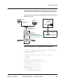
Cadant® C3™ CMTS
Cable Modem Termination System
C3 CMTS
User Documentation
Release 4.3, Standard
November 2005
ARRIS PROPRIETARY
This document contains proprietary information of ARRIS, Inc. and is not to be disclosed
or used except in accordance with applicable agreements.
© 2005 ARRIS, Inc.
All Rights Reserved
11/14/05
Copyright and Trademark Information
Cadant® C3™
Cadant® C4™
Keystone™ D5™
ARRIS® and Arris Interactive are trademarks of ARRIS International, Inc. Cadant C3 CMTS is a
registered trademark of ARRIS Licensing Company. All other trademarks and registered
trademarks are the property of their respective holders.
Every attempt has been made to capitalize and spell correctly the trademarked and service
marked terms used in this manual. ARRIS does not attest to the accuracy of these terms and their
usage. Any misspelling or misuse of a term should not be construed as affecting the validity of its
trademark or service mark.
All information contained in this document is subject to change without notice. ARRIS reserves the
right to make changes to equipment design or program components, as progress in engineering,
manufacturing methods, or other circumstances may warrant.
The ARRIS Cadant® C3™ Cable Modem Termination System (CMTS) has been qualified by
CableLabs® for DOCSIS™1.1 and 2.0 and by tComLabs for Euro-DOCSIS 1.1.
© 2005 ARRIS, Inc.
All rights reserved.
Table of Contents
C3 CMTS
User Documentation
1
2
3
About this Manual
Scope
1-1
In this Document
1-2
Conventions Used in This Manual
1-3
For More Information
1-4
FCC Statement
1-4
Safety
1-4
Getting Started
About the C3 CMTS
2-1
Fast Start
2-2
Introducing the ARRIS Cadant C3 CMTS
2-2
Major Components of the Cadant C3 CMTS
2-8
CMTS Installation
Planning the Installation
4
3-1
Bridge Operation
Terms and Abbreviations
Release 4.3, Standard
ARRIS PROPRIETARY — All Rights Reserved
4-2
iii
Table of Contents
5
C3 CMTS
Bridging Features
4-3
Bridge Concepts
4-4
Bridge Binding
4-14
IP Addressing
4-16
Attaching Bridge Groups
4-18
Incoming Traffic Allocation to a Sub-Interface
4-19
Providing Multiple ISP Access
Open Access
5-1
Cable-VPN Implementation
5-3
Using the Modem IP Address to allocate CPE to a VPN
5-5
Using a Modem Configuration File to Allocate CPEs to a VPN
6
IP Routing
Routing Concepts
6-1
About RIP
6-3
About OSPF
6-3
Loopback Interfaces
6-8
Multicast Operations
6-9
Layer 3 Multicast Operation
6-13
OSPF Point-To-Multipoint
6-14
Route-Maps
6-16
6-17
Match Clauses
6-19
Provisioning Route-Maps
6-20
Displaying Route-maps
6-20
OSPF Route Redistribution Filtering
iv
6-12
Routing Command Overview
OSPF User interface
7
5-11
6-21
Managing Cable Modems
Changing the Upstream Channel Type
7-3
DHCP
7-3
Data Errors
7-23
Upgrading Modem Firmware
7-24
ARRIS PROPRIETARY — All Rights Reserved
11/14/05
C3 CMTS
Table of Contents
Provisioning Upstream Load Balancing
8
Configuring Security
Overview
8-2
Physically Separating Data
8-3
Filtering Traffic
8-7
Cable Interface VLANS
8-28
Cable Source Verify
8-32
Packet Throttling
8-34
Broadcast Throttling
8-35
IP Throttling
8-35
Simple Law Enforcement Monitoring (SLEM)
8-36
Configuring SSH
8-38
Configuring AAA
8-43
TACACS+ Commands
9
7-27
8-47
Service Procedures
Removing Power for Servicing
9-2
Resetting the Power Supplies
9-3
Replacing a Power Supply
9-4
Fan Tray Replacement
9-5
Replacing the Battery
9-5
Replacing the RF Card
9-8
Replacing Fuses
9-9
Resetting the CMTS after Thermal Overload
9-10
Upgrading the CMTS Software
9-11
Enabling Licensing Features
9-17
Upgrading Dual Upstream Receivers (DOCSIS 2.0 Systems)
9-19
Release 4.3, Standard
ARRIS PROPRIETARY — All Rights Reserved
v
Table of Contents
10
C3 CMTS
Command Line Interface Reference
User Mode Commands
A
User Mode SHOW Commands
10-12
Privileged Mode Commands
10-27
Privileged SHOW Commands
10-46
Global Configuration Commands
10-98
Configure-keychain-key Mode
10-176
Configure Line Mode
10-178
Interface Configuration Commands
10-180
Router Configuration Mode
10-248
Specifications
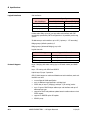
Product Specifications
B
B-2
Debug—What to Do if DHCP is Not Working
D
B-5
Advanced Bridging
B-13
DHCP Server Configuration
B-14
Standard Ethernet Backbone
B-18
Wireless Cable Applications
Overview
C-1
Feature Summary
C-2
Configuration
C-2
User Interface
C-3
SNMP
C-4
DS1 Applications
Provisioning Summary
vi
A-1
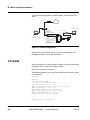
CMTS Configuration Examples
C3 Install
C
10-6
ARRIS PROPRIETARY — All Rights Reserved
D-2
11/14/05
C3 CMTS
Table of Contents
Example Modulation Profile
D-2
Example Cable Modem Configuration File
D-3
E
SLEM MIB
F
Factory Defaults
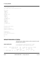
Default Configuration Listing
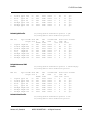
Default Modulation Profiles
G
H
F-2
F-18
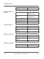
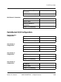
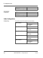
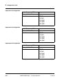
Configuration Forms
Fastethernet 0/0 Configuration
G-3
Fastethernet 0/1 Configuration
G-4
Cable Configuration
G-6
C3 CMTS Syslog Events and SNMP Traps
Syslog Events
H-1
SNMP Traps
H-7
Release 4.3, Standard
ARRIS PROPRIETARY — All Rights Reserved
vii
Table of Contents
viii
C3 CMTS
ARRIS PROPRIETARY — All Rights Reserved
11/14/05
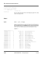
List of Figures
Figure 2-1:
Major components of the C3 CMTS
2-5
Figure 2-2:
Front panel of C3
2-5
Figure 2-3:
Rear panel port identification
2-7
Figure 3-1:
Earthing using only DC power
3-2
Figure 3-2:
Example positioning of the M4 nut and lock washers
3-3
Figure 3-3:
Connector and pin locations
3-4
Figure 3-4:
Example of CATV System Connections
3-6
Figure 3-5:
CMTS rear view
3-8
Figure 3-6:
LCD location
3-9
Figure 3-7:
Rear panel connectors
3-11
Figure 3-8:
Rear cable connections
3-21
Figure 4-1:
Example of a bridge group
4-4
Figure 4-2:
Example of a sub-interface to access different bridge groups
4-5
Figure 4-3:
Example of a “Management Access Only” interface
4-6
Figure 4-4:
Illustration of the default bridge configuration
4-7
Figure 4-5:
Illustration of the factory default configuration
4-8
Figure 4-6:
Example of a bridging network configuration
4-9
Figure 4-7:
Data flow when FastEthernet 0/1 is the boot interface
4-11
Figure 4-8:
Default, V2.0 compatible, operating mode
4-12
Figure 4-9:
Example of Bridge group 0
4-13
Figure 4-10: Example of Bridge group 1
4-13
Release 4.3, Standard
ARRIS PROPRIETARY — All Rights Reserved
ix
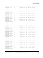
List of Figures
x
C3 CMTS
Figure 4-11: Example of CMTS management traffic
4-14
Figure 4-12: Bridge binding on US Layer 2 broadcast
4-15
Figure 4-13: Example of legal use of the bridge bind command
4-16
Figure 4-14: Example of IP addressing
4-17
Figure 4-15: Example of attaching bridge groups
4-19
Figure 4-16: Example of ARRIS VSE with a VPN ID of 000Bh
4-22
Figure 4-17: Example configuration file with VSE information
4-23
Figure 5-1:
Example of an Open Access system
5-2
Figure 5-2:
Example network diagram
5-6
Figure 5-3:
Bridging data flow through the C3
5-7
Figure 5-4:
Diagram of network used in this example
5-12
Figure 5-5:
How the C3 bridges data in the example
5-13
Figure 5-6:
How the C3 bridges data in this configuration
5-18
Figure 6-1:
OSPF two-level hierarchy
6-6
Figure 6-2:
Example of an OSPF-based network redistributing RIP routes
6-7
Figure 7-1:
DHCP traffic flow through the C3 in transparent mode
7-4
Figure 7-2:
DHCP traffic flow with dhcp-giaddr enabled
7-15
Figure 8-1:
Simplified network diagram
8-21
Figure 8-2:
Example of bridging traffic to the FastEthernet
8-25
Figure 8-3:
RFC 3924 framework
8-37
Figure 8-4:
AAA Security Model
8-43
Figure 8-5:
Method list example
8-44
Figure 9-1:
Front panel latch
9-2
Figure 9-2:
Front panel faceplate
9-2
Figure 9-3:
Reset switch
9-3
Figure 9-4:
Power supply
9-4
Figure 9-5:
Fan tray
9-5
Figure 9-6:
Location of battery on CPU card
9-6
Figure 9-7:
Removing the CPU card
9-7
ARRIS PROPRIETARY — All Rights Reserved
11/14/05
C3 CMTS
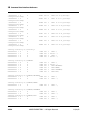
List of Figures
Figure 9-8:
Replacing the RF card
9-8
Figure 9-9:
Fuse location
9-9
Figure 9-10: Location of the SW2 switch
9-10
Figure 9-11: Location of compact flash
9-14
Figure 9-12: IF cable routing
9-19
Figure 9-13: Adding a MAC/PHY card
9-20
Figure 9-14: Securing the dual receiver board
9-21
Figure 9-15: Fully populated MAC/PHY card
9-22
Figure B-1:
Simple configuration
B-2
Figure B-2:
Default allocation of sub-interfaces to the default bridge groups
B-7
Figure B-3:
Example of bridge-group capabilities
B-9
Figure B-4:
Example of how an ISP based DHCP server manages CPE IP addresses
B-11
Figure B-5:
Example of all the C3v advanced bridging and VLAN abilities
B-13
Figure B-6:
Example of “open access” without using 802.1Q backbone VLANs
B-19
Figure B-7:
Example of a pure routing model
B-22
Figure B-8:
Example of the equivalent routing version of simple bridging
B-24
Figure B-9:
Example of a hybrid operation
B-26
Release 4.3, Standard
ARRIS PROPRIETARY — All Rights Reserved
xi
List of Figures
xii
C3 CMTS
ARRIS PROPRIETARY — All Rights Reserved
11/14/05
1
About this Manual
Topics
Page
Scope
1
In this Document
2
Conventions Used in This Manual
3
For More Information
4
FCC Statement
4
Safety
4
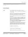
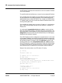
Scope
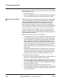
This document provides necessary procedures to install, operate, and
troubleshoot the ARRIS Cadant C3 CMTS in a DOCSIS®- or EuroDOCSIScompatible environment. It is intended for cable operators and system
administrators who configure and operate the CMTS. It is assumed the
reader is familiar with day-to-day operation and maintenance functions in
networks that rely on TCP/IP protocols and hybrid fiber/coax (HFC) cable
networks.
This document applies to version 4.3 of the CMTS software, including
minor revisions and point releases.
Release 4.3, Standard
ARRIS PROPRIETARY — All Rights Reserved
1-1
1 About this Manual
In this Document
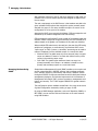
This manual provides the following content:
1-2
•
Chapter 2, “Getting Started,” provides a brief overview of the Cadant
C3 CMTS and its components.
•
Chapter 3, “CMTS Installation,” describes how to unpack and install
the CMTS including how to bring up the CMTS from an “out of box”
condition to full operation.
•
Chapter 4, “Bridge Operation,” describes basic bridge operation of the
CMTS and issues in upgrading to L3 capable code to restore DHCP
operation.
•
Chapter 5, “Providing Multiple ISP Access,” describes the supported
802.1Q VLAN capabilities.
•
Chapter 6, “IP Routing,” describes how to configure the C3 CMTS as a
layer 3 router.
•
Chapter 7, “Managing Cable Modems,” describes common procedures
for operating and troubleshooting DOCSIS systems.
•
Chapter 8, “Configuring Security,” describes methods that can be used
to improve security of management and user traffic.
•
Chapter 9, “Service Procedures,” describes basic service procedures.
•
Chapter 10, “Command Line Interface Reference,” describes the
command line interface for managing and configuring the CMTS.
•
Appendix A, “Specifications,” lists physical, electrical, and networking
specifications.
•
Appendix B, “CMTS Configuration Examples,” provides a configuration
for a bench top trial. Includes both RF and CLI configuration.
•
Appendix C, “Wireless Cable Applications,” describes features related
to wireless cable support.
•
Appendix D, “DS1 Applications,” provides example configurations for
providing “circuit emulation” services.
•
Appendix E, “SLEM MIB,” provides the Simple Law Enforcement Monitoring (SLEM) MIB.
•
Appendix F, “Factory Defaults,” contains default configuration information.
•
Appendix G, “Configuration Forms,” provides a form listing essential
configuration parameters.
•
Appendix H, “C3 Syslog Events and SNMP Traps,” provides a listing of
supported traps and syslog events.
ARRIS PROPRIETARY — All Rights Reserved
11/14/05
C3 CMTS User Guide
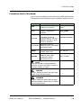
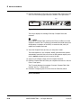
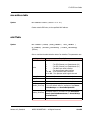
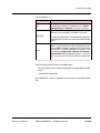
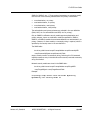
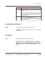
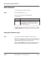
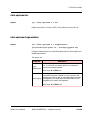
Conventions Used in This Manual
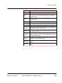
Various fonts and symbols are used in this manual to differentiate text that
is displayed by an interface and text that is selected or input by the user:
Highlight
Use
Examples
bold
Keyword: Text to be typed
literally at a CLI prompt.
Type exit at the
prompt.
italics
Indicates a required user
parameter.
ping {ipaddr}
A parameter in a CLI command. ping {ipaddr}
bracketed
A parameter enclosed in
[square] brackets is optional; a
parameter enclosed in {curly}
brackets is mandatory.
terminal [no] monitor
monospaced
Display text. Shows an
interactive session of commands
and resulting output.
ipaddr
IP address: enter an IP address
in dotted-quad format
10.1.105.128
macaddr
MAC address: enter a MAC
address as three 4-digit
hexadecimal numbers,
separated by periods.
00a0.731e.3f84
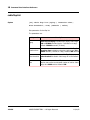
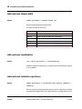
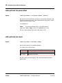
NOTE
Notes are intended to highlight additional
references or general information related to a
procedure, product, or system.
CAUTION
Caution: Indicates an action that may disrupt
service if not performed properly.
WARNING
Danger: Indicates an action that may cause
equipment damage, physical injury, or death if
not performed properly.
Release 4.3, Standard
ARRIS PROPRIETARY — All Rights Reserved
1-3
1 About this Manual
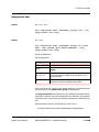
For More Information
For more detailed information about DOCSIS, refer to the following technical specifications, available online at www.cablelabs.com.
•
Radio Frequency Interface (RFI) Specification—defines how data is
passed over the cable
•
Operations Support System Interface (OSSI) Specification—defines
how DOCSIS components can be managed by the cable operator
•
Baseline Privacy Interface (BPI) Specification—defines how data is
encrypted while traveling on the cable to keep it private
•
Computer to Modem Communications Interface (CMCI) Specification—defines how PCs can communicate to cable modems
For an overview of DOCSIS 2.0 features, see the ARRIS white paper
“Getting to Know the New Kid on the Block” at
http://www.arrisi.com/products_solutions/applications/white_papers/DOCSIS_20_Getting_To_Know_The_New_Kid.pdf
FCC Statement
This device complies with part 15 of the FCC Rules. Any changes or modifications not expressly approved by the grantee of this device could void
the user’s authority to operate the equipment.
Safety
Normal lightning and surge protection measures are assumed to have
been followed in the RF plant that the ARRIS Cadant C3 CMTS RF input
and output is connected to.
If AC supply is used to power the ARRIS Cadant C3 CMTS, suitable surge
and lightning protection measures should be taken with this supply.
The equipment rack the ARRIS Cadant C3 CMTS is mounted in should have
a separate safety ground connection. This ground should be wired in
accordance with National Electric Code (NEC) requirements for domestic
applications and paragraph 2.6 of EN60950/IE950 for international applications.
The safety ground wire must be #6 AWG or larger, and it must connect
the equipment rack directly to the single-point ground in the service panel.
The single-point ground can be an isolated ground or the AC equipment
ground in the service panel or transformer. Depending on the distances
between the cabinets and the location of the service panel, the wiring can
be either daisy-chained through the cabinets or run independently from
each cabinet to the service panel.
1-4
ARRIS PROPRIETARY — All Rights Reserved
11/14/05
C3 CMTS User Guide
The remaining non-RF and non-AC supply connections of the ARRIS
Cadant C3 CMTS should be made by SELV rated circuits.
Release 4.3, Standard
ARRIS PROPRIETARY — All Rights Reserved
1-5
1 About this Manual
1-6
ARRIS PROPRIETARY — All Rights Reserved
11/14/05
2
Getting Started
Topics
Page
About the C3 CMTS
1
Fast Start
2
Introducing the ARRIS Cadant C3 CMTS
2
Major Components of the Cadant C3 CMTS
8
This chapter introduces the ARRIS Cadant C3 Cable Modem Termination
System (CMTS) and provides background information about the DataOver-Cable Service Interface Specification (DOCSIS) standards with which
the product complies.
About the C3 CMTS
ARRIS has designed the C3 specifically for DOCSIS and EuroDOCSIS specifications.
From its inception, it has been designed to take advantage of already
defined Advanced Physical Layer features as well as new noise suppression
technologies to deliver the most efficient utilization of the upstream spectrum. The hardware platform itself has been designed to scale to the most
demanding needs of the operator from a packet classification and features
perspective. The processing power of the system is capable of accommodating the emerging needs of cable operators worldwide.
Release 4.3, Standard
ARRIS PROPRIETARY — All Rights Reserved
2-1
2 Getting Started
With dual RISC processors in its architecture, the C3 supplies the
processing power needed to support high volumes of traffic, with excellent
latency control. The CMTS has scalable transmit and receive capacity,
which can be configured to support one channel downstream and up to six
channels upstream. It supports multiple network protocols, and multiple
architectures such as PPPoE and NetBEUI, making it easy to add to existing
router- or switch-based cable networks. Easy-to-use system management
tools include an industry-standard command-line interface.
DOCSIS Compliance
The C3 is DOCSIS 1.1, DOCSIS 2.0, and EuroDOCSIS 1.1 qualified. The C3
is also compliant with EuroDOCSIS-2.0 when used with the DOCSIS 2.0 RF
card.
The C3 CMTS works on any cable system with any DOCSIS or EuroDOCSIS
compliant modems.
Fast Start
The basics of commissioning the Cadant C3 CMTS are covered in Chapter
3 and a complete example of a bench top installation is also provided in
Appendix B.
Introducing the ARRIS Cadant C3 CMTS
The C3 is a flexible, powerful, and easy-to-use Cable Modem Termination
System (CMTS). It is DOCSIS 1.1, DOCSIS 2.0, and EuroDOCSIS 1.1 qualified and compliant with EuroDOCSIS 2.0 standards, which includes specifications for features such as security enhancements, telephony, QoS, and
tiered services.
The C3 has dual 10/100/1000 Mbps Ethernet interfaces and supports a 64
or 256 Quadrature Amplitude Modulation (QAM) cable TV downstream
channel, and up to six variable-rate Quadrature Phase Shift Keying (QPSK)
or 8, 16, 32, or 64 QAM upstream channels. Easy-to-use system management tools include an industry-standard command-line interface.
2-2
ARRIS PROPRIETARY — All Rights Reserved
11/14/05
C3 CMTS User Guide
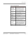
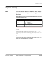
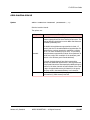
Table 2-1: C3 Features and Benefits
Features
Advanced TDMA
support: 8QAM,
32QAM, and 64QAM
200 KHz to 6.4 MHz
channel width
Benefits
Designed from the ground up to support
advanced symmetrical data rate applications
based on the DOCSIS 1.0, 1.1, and 2.0
specifications while maintaining compatibility
with existing modems. Delivers superior
performance in real-world cable plants through
advanced noise cancellation technology
Compact size
Full DOCSIS 1.1 with ATDMA support, or
DOCSIS 2.0 with ATDMA and SCDMA support, in
a one-rack unit high system
Operator selectable
Layer 2 and Layer 3
forwarding
Allows operators to choose the routing method
most appropriate to their needs
ACL support
Up to 30 ACLs with 30 entries per ACL may be
applied to any interface
Full upstream support
5 to 65 MHz
Allows better utilization of upstream frequency
space for DOCSIS in plants outside of North
America
DOCSIS and
Provides flexibility for operators by supporting
EuroDOCSIS support— either protocol on the same unit with no
selectable in software additional hardware to purchase
Release 4.3, Standard
Efficient bandwidth
management
User-configurable dynamic upstream channel
bandwidth allocation allows the ARRIS Cadant
C3 to respond to network conditions in real-time.
Load-balancing allows the cable operator to
automatically or manually distribute upstream
traffic evenly across available channels.
Integrated RF upconverter
Complete ready-to-use CMTS in only one rack
unit (1.75 in. of space)
ARRIS PROPRIETARY — All Rights Reserved
2-3
2 Getting Started
Table 2-1: C3 Features and Benefits
Features
Benefits
Provides support for up to 200 simultaneous
telephony connections.
DOCSIS DSx signalling occurs directly between
the C3 and an MTA. DSx messages can Add
(DSA), Change, (DSC) or Delete (DSD) service
flows dynamically.
DSx support
SIP Dynamic Polling
The C3 currently supports CPE-initiated DSx
transactions. For voice traffic, DSx is used to
create UGS flows upstream on the fly. Unlike BE
flows, data rates of UGS flows are guaranteed by
the CMTS. In the Downstream direction, DSx is
used to create flows with a Minimum reserved
rate. Once established, these flows take priority
over all others in the Downstream direction.
SIP signalling can be used to provide voice
services using legacy CPE that does not support
DOCSIS DSx. SIP Dynamic Polling dynamically
creates upstream and downstream data flows
for voice traffic; as with DSx, these flows have
priority over DOCSIS BE data flows. When the
voice call terminates, the bandwidth used by
these flows is freed for use by other voice or
data traffic.
To enable this feature, configure the Cable
Modem at the customer premises with a special
configuration file. When the C3 detects
appropriate SIP messages coming from the
Cable Modem, the C3 activates prioritized flows
to carry the voice traffic.
Contact your ARRIS Technical Support
representative if you require more information
on this feature.
2-4
ARRIS PROPRIETARY — All Rights Reserved
11/14/05
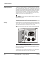
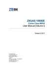
C3 CMTS User Guide
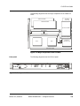
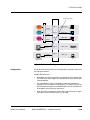
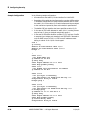
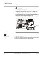
The following diagram shows the major components of the Cadant C3
CMTS.
Aux WAN
(reserverd)
MAC & PHY Blade
WAN & CPU Blade
Upconverter Blade
Fantray PCB
cPCI Midplane
Power Midplane
Upconverter Midplane
PSU1
Front Pane
Extension Card
PSU2
Front Panel Display
Figure 2-1: Major components of the C3 CMTS
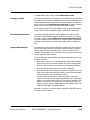
Front panel
The following diagram shows the C3 front panel.
NS
FA
0 1 2 3 4 5
RX RX RX RX RX RX
X 0 1
AU FE FE
UP
N
O
C
US
U1 U2 AT
PS PS ST
LCD
Figure 2-2: Front panel of C3
Release 4.3, Standard
ARRIS PROPRIETARY — All Rights Reserved
2-5
2 Getting Started
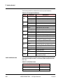
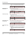
The following table lists and describes the front panel indicators.
Table 2-2: Front panel indicators
Name
FANS
RX0 to
RX5
Indication
Green
Normal operation.
Red
One fan has failed.
Flashing Red
More than one fan has failed.
Green
Upstream is active.
Flashing Green
Upstream is in use.
AUX
FE 0
FE 1
UP CON
PSU 1
PSU 2
STATUS
not used
Green
WAN network port is linked.
Flashing Green
WAN network port is active.
Green
MGMT network port is linked.
Flashing Green
MGMT network port is active.
Green
Upconverter is operating properly.
Off
Upconverter not installed.
Green
Power supply 1 (on the left side behind the
front panel) is operating properly.
Flashing Red
Power supply 1 fault detected.
Green
Power supply 2 (on the right side behind
the front panel) is operating properly.
Flashing Red
Power supply 2 fault detected.
Flashing Amber
CMTS is booting.
Green
Normal operation.
Flashing Red
CMTS fault detected.
Downstream output with signal level
attenuated by 30 dB
RF test
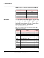
Traffic LED flash rates
Description
The Traffic LED flashes at variable rates to indicate the relative amount of
data flowing through the CMTS. The following table interprets the LED
flash rate.
Table 2-3: LED flash rates
Traffic Rate
2-6
Flash Rate
>2000 packets per second
50 milliseconds
>1000 packets per second
100 milliseconds
>500 packets per second
150 milliseconds
ARRIS PROPRIETARY — All Rights Reserved
11/14/05
C3 CMTS User Guide
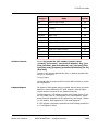
Table 2-3: LED flash rates
Traffic Rate
Rear Panel
Cable 1/0
Downstream
Flash Rate
>300 packets per second
200 milliseconds
>100 packets per second
250 milliseconds
>10 packets per second
300 milliseconds
less than 10 packets per second
500 milliseconds
0 packets per second
not flashing
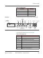
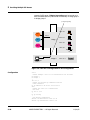
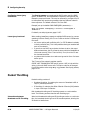
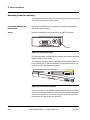
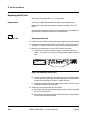
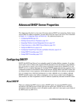
The following diagram shows the locations of ports on the rear panel.
Debug
LEDs
Serial
Alarm
Compact
Flash
Cable 1/0
Upstreams 0-5
FE1
FE0
DC power
Downstream
IF
AC power
F2 F1
Fuses
Figure 2-3: Rear panel port identification
The following table describes the ports on the rear panel.
Table 2-4: Rear panel ports
Port
Release 4.3, Standard
Interface
FE1
10/100/1000Base-T interface
FE0
10/100/1000Base-T interface
AC power
Input receptacle for 90 to 264 volts AC
DC power
Input receptacle for –40 to –60 volt DC
RS232
RS-232 serial port for initial setup (38400/N/8/1)
Alarm
Reserved for future use.
RX0
Upstream #1 (cable upstream 0)
RX1
Upstream #2 (cable upstream 1)
RX2
Upstream #3 (cable upstream 2)
RX3
Upstream #4 (cable upstream 3)
ARRIS PROPRIETARY — All Rights Reserved
2-7
2 Getting Started
Table 2-4: Rear panel ports
Port
Interface
RX4
Upstream #5 (cable upstream 4)
RX5
Upstream #6 (cable upstream 5)
Downstream
Downstream output from upconverter
Intermediate frequency (IF) output (43.75 MHz for NA
Downstream IF
DOCSIS; 36.125 MHz for EuroDOCSIS) which may be
Output
routed to an external upconverter.
NOTE
ARRIS does not support simultaneous use of the Downstream and
Downstream IF outputs.
Major Components of the Cadant C3 CMTS
Redundant Power Supplies
The Cadant C3 CMTS supports simultaneous powering from AC or DC
using one or two power supplies. If two power supplies are installed, the
load is shared between both. In this configuration, one power supply may
fail without impacting system operations. The CMTS has separate connections for AC and DC power.
Up-Converter
The Cadant C3 CMTS incorporates a state-of-the-art up-converter for the
downstream signal. The signal may be output in either the DOCSIS (6 MHz
wide—Annex B) or EuroDOCSIS (8 MHz wide—Annex A) formats. The integrated up-converter can generate the full DOCSIS/EuroDOCSIS power
range across the entire frequency. The up-converter is frequency agile.
Either the command line interface or SNMP can be used to tune the upconverter and configure it for DOCSIS or EuroDOCSIS operation.
The CMTS is capable of using various frequency plans, including North
American Standard, IRC, HRC, Japanese, European PAL, and European
SECAM. For more information on supported channel plans, see Appendix
B. The C3 can operate at any frequency (in 62.5 KHz steps) within the
band.
Wideband Digital Receiver
The CMTS incorporates a wideband digital receiver for each upstream
channel. The digital receiver section allows spectrum analysis as well as
advanced digital signal processing to remove noise (including ingress) and
deliver the highest possible performance.
Media Access Control (MAC)
Chip
The MAC chip implements media access control (MAC) protocol and
handles MPEG frames. It also supports Direct Memory Access (DMA) for
high data transfer performance.
2-8
ARRIS PROPRIETARY — All Rights Reserved
11/14/05
C3 CMTS User Guide
Ethernet Interfaces
The CMTS has two Ethernet interfaces, each which is capable of operating
at 10, 100, or 1000 megabits per second. The ports are capable of both
half-duplex and full-duplex operation and automatically negotiate to the
appropriate setting. One port may be dedicated to data while the other
port may be used for out-of-band management of the C3 and (optionally)
cable modems.
Management Schemes
The CMTS management mode determines how traffic is assigned to the
Ethernet ports, and may be selected through the C3 configuration. For
example:
•
C3 management traffic can be restricted to one Ethernet port, and all
subscriber traffic restricted to the other Ethernet port.
•
Cable modem traffic can be directed to either Ethernet port as
required.
CPU
The CMTS is built around dual, state-of-the art, reduced instruction set
(RISC) processors. One processor is dedicated to data handling while the
other processor performs control functions including SNMP.
Flash Disk
The C3 uses a 128MB Compact Flash card to store operating software and
configuration files. The disk may be removed without affecting normal
operation; however, the C3 disables all configuration-related CLI and
SNMP functions until you replace the disk.
Release 4.3, Standard
ARRIS PROPRIETARY — All Rights Reserved
2-9
2 Getting Started
2-10
ARRIS PROPRIETARY — All Rights Reserved
11/14/05
3
CMTS Installation
Topics
Page
Planning the Installation
1
Network Requirements
1
Power Requirements
2
Earthing
2
Cable Requirements
4
Cable Plant Requirements
5
Unpacking the CMTS
6
Mounting the CMTS
7
Initial Configuration
10
Use this chapter to install the Cadant C3 CMTS.
Planning the Installation
Network Requirements
Release 4.3, Standard
The CMTS may be connected to your network using one or both Ethernet
interfaces. If it is desired to keep subscriber data traffic physically separate
from management traffic, then both ethernet interfaces must be used.
Alternatively, data and management traffic can be sent on different VLANS
via a single Ethernet interface. Regardless of the connection method
selected, at least one network connection is required to the CMTS.
ARRIS PROPRIETARY — All Rights Reserved
3-1
3 CMTS Installation
Power Requirements
To assure high system reliability, the C3 chassis supports two hot-swappable, load-sharing power supply modules. A single supply can provide all
the power that a fully loaded system needs with sufficient safety margin.
Each type of power supply has a separate power connector mounted on
the rear panel of the C3 chassis. The power connectors are typically
plugged into the AC power or DC power distribution unit of the rack or
cabinet using the power cords supplied with the C3.
NOTE
Make sure that the power circuits have sufficient capacity to power the C3
before connecting power.
To disconnect power from the C3 for servicing, remove both power leads
(AC and DC) from the rear socket. The C3 has no power switch.
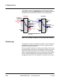
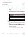
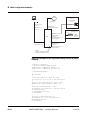
Earthing
Reliable earthing of rack mounted equipment should be maintained. See
Safety, page 1-4, for common safety considerations. Also consider using
power strips instead of direct connections to branch circuits.
When using only DC power, earth the C3 chassis using the supplied M4
stud.
DC
AC - 110V
Figure 3-1: Earthing using only DC power
Use an M4 nut and M4 lock washers with the parts stacked as shown in
the example figure below.
If using DC power, then the Earthing conductor on the DC power cable
may be secured under either the top nut or the bottom nut.
3-2
ARRIS PROPRIETARY — All Rights Reserved
11/14/05
C3 CMTS User Guide
Lockwasher
DC Feed
Ground
Chassis
Ground
Lockwasher
Metal
Figure 3-2: Example positioning of the M4 nut and lock washers
AC powering
The AC power modules require 100 to 240 volt, 2A, 47 to 63 Hz AC power.
The socket-outlet must be properly earthed.
DC powering
The DC power modules requires –40 to –60 V DC, 4A power from a SELV
rated source. The DC power source must have an over current protection
device rated at 10 Amp.
The external DC cable assembly must not be modified in the field; route
any excess length to avoid snags.
Connect both Feed 1 and Feed 2 to the DC power source even if only one
DC power supply is to be installed. This allows placing a single DC power
supply in either of the two possible locations, or placing two DC power
supplies in the chassis.
Release 4.3, Standard
ARRIS PROPRIETARY — All Rights Reserved
3-3
3 CMTS Installation
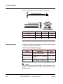
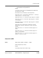
The following diagram shows the connector and pin locations.
DC RETURN BLACK 1
-40 to -60V FEED 2 (RED) 2
-40 to -60V FEED 2 (WHITE) 3
Signal
To
AWG
Color
DC Return
Pin 1
18
Black
-40 to -60V Feed 1
Pin 2
18
Red
-40 to -60V Feed 2
Pin 3
18
White
Figure 3-3: Connector and pin locations
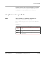
Cable Requirements
A variety of cables and connectors and the tools to work with them must
be obtained to complete the installation.
Table 3-1: Cable and connector types
Cable
Wire Type
Connector
Type
Serial console
(included with C3)
9 pin RS-232 serial cable
DB-9M
Ethernet connections
Category 3, 4, 5, or 5E twisted
pair cable
RJ-45
CATV
RG-59 coaxial cable (all)
RG-6 (DOCSIS 2.0 cards only)
F
NOTE
Use only RG-59 coaxial cable with DOCSIS 1.1 cards. RG-6 cable is not
suitable for use with the connectors on these cards, but may be used with
DOCSIS 2.0 cards.
3-4
ARRIS PROPRIETARY — All Rights Reserved
11/14/05
C3 CMTS User Guide
Ethernet Connections
The C3 provides two 10/100/1000BaseT Ethernet ports to allow connection to a terminating router, server, or other networking devices such as a
hub, switch, or bridge.
Both Ethernet connectors are standard RJ-45 connectors. For 10BaseT and
100BaseT, unshielded cable may be used. For 1000BaseT, use shielded
category 5E wire.
Cable Plant Requirements
The RF cable plant should be designed so that all RF ports connect to SELV
circuits (meeting the requirements of SELV as defined in UL60950). You
must provide suitable protection between these ports and the CATV
outside plant.
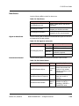
Table 3-2: Downstream RF cable plant requirements
Parameter
Frequency Range
Value
88 to 858 MHz (DOCSIS / JDOCSIS)
112 to 858 MHz (EuroDOCSIS)
Carrier-to-Nose ratio at the
30 dB
RF input to the cable modem
Channel bandwidth
6 MHz (DOCSIS / JDOCSIS)
8 MHz (EuroDOCSIS)
Table 3-3: Upstream RF cable plant requirements
Parameter
Frequency Range
Release 4.3, Standard
Value
5 to 42 MHz (DOCSIS)
5 to 65 MHz (EuroDOCSIS / JDOCSIS)
Carrier-to-noise ratio at the
RF input to the C3
At least 10 dB
Channel Bandwidth
200 KHz, 400 KHz, 800 KHz, 1600 KHz,
3200 KHz, 6400 KHz
ARRIS PROPRIETARY — All Rights Reserved
3-5
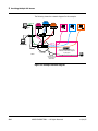
3 CMTS Installation
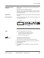
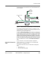
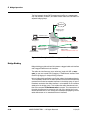
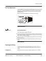
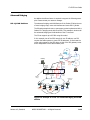
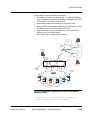
CATV System Connections
The C3 transmitter output is the downstream RF connection (head-end to
subscriber). The receiver inputs (subscriber to head end) are the upstream
RF connections. There are 2 upstream connections per upstream receiver
module with a maximum of 6 upstream connections per CMTS.
Figure 3-4: Example of CATV System Connections
Unpacking the CMTS
The carton in which the Cadant C3 CMTS is shipped is specifically designed
to protect the equipment from damage. Save all shipping materials in case
the product needs to be returned to the manufacturer for repair or
upgrade.
Unpack the equipment carefully to ensure that no damage is done and
none of the contents is lost.
Package Contents
The Cadant C3 package should contain the following items:
•
Cadant C3 CMTS
•
Rack mounting “ears” and mounting screws
•
Power cord
•
Serial console cable
•
Safety and Quick Start guides
If any of these items are missing, please contact your ARRIS service representative.
Action
3-6
After unpacking the equipment, but before powering it up the first time,
read this manual in its entirety, then perform a visual inspection of the
equipment as follows:
ARRIS PROPRIETARY — All Rights Reserved
11/14/05
C3 CMTS User Guide
1 Look for the following potential problems:
•
Physical damage to the chassis or components
•
Loose connectors
•
Loose or missing hardware
•
Loose wires and power connections
2 If any of the above are found, do not attempt to power on the CMTS.
Contact your local service representative for instructions.
Mounting the CMTS
The C3 CMTS is 1.75 in. (4.4 cm) high and is suitable for mounting in a
standard 19 in. (48.3 cm) relay rack.
NOTE
Install the CMTS in a restricted access location.
Environmental requirements
Installation of the equipment in a rack should not restrict airflow where
marked on the top of the C3 case. In particular, provide adequate side
clearance.
Mount the C3 properly to prevent uneven mechanical loading on the
chassis. Improper mounting can cause premature failure and potentially
hazardous conditions.
When installed in a closed or multi-unit rack assembly, the operating
temperature inside the rack environment may be higher than ambient
temperature. The C3 should be installed in an environment where the
ambient temperatures remains below 40° Celsius.
Procedure 3-1
Follow these steps to mount the CMTS in a 19-inch rack.
1 Install one rack mounting bracket on each side of the CMTS so that the
two-hole side is closest to the front of the CMTS and the brackets protrude
away from the CMTS. Use four screws to fasten each bracket to the CMTS.
CAUTION
Heavy load. Handle with care.
The CMTS weighs approximately 22 lbs (10 Kg). If necessary, have a
second person hold the CMTS while mounting it to the rack.
2 Mount the CMTS in the rack and secure it using two screws on each side.
End of procedure
Release 4.3, Standard
ARRIS PROPRIETARY — All Rights Reserved
3-7
3 CMTS Installation
Procedure 3-2
Connecting Cables
Use this procedure to connect RF, data, and power cables to the CMTS.
Depending on the configuration ordered, the C3 may have 2, 4, or 6
upstreams.
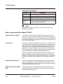
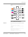
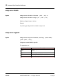
CMTS Rear View
Refer to the following figure to locate the cable ports.
DC power
Cable 1/0
Downstream
FE1
AC power
FE0
Cable 1/0
Upstreams 0-5
-
Figure 3-5: CMTS rear view
Procedure 3-3
Follow these steps to connect cables to the CMTS.
1 Connect the upstream cable from your plant to the appropriate upstream
ports. The upstream ports are located on the lower board, and are
numbered left to right as viewed from the rear.
NOTE
Connect all RF ports to SELV circuits (meeting the requirements of SELV
as defined in UL60950). Your headend must provide suitable protection
between the RF ports and the CATV outside plant.
2 Connect the downstream cable to the downstream port (the F-connector
located at the upper left).
3 Connect a PC to the serial connector (male DB9 connector on the upper
interface module). The pin-out for this connector is designed to function
with a PC when used with a straight-through cable, and is shown in the
following table. The serial port operates at 38,400 bps with 8 data bits, 1
stop bit, and no parity bit.
Pin
3-8
Signal
1
Data Carrier Detect (DCD)
2
Receive Data (RD)
ARRIS PROPRIETARY — All Rights Reserved
11/14/05
C3 CMTS User Guide
Pin
Signal
3
Transmit Data (TD)
4
Data Terminal Ready (DTR)
5
Ground (GND)
6
Data Set Ready (DSR)
7
Request to Send (RTS)
8
Clear to Send (CTS)
9
Unused
4 (optional) Connect an Ethernet cable between the FE1 port and the
network manager.
5 Connect an Ethernet cable between the FE0 port and the network bridge
or router.
6 Make the power connection as follows:
•
If using AC power, connect the power cord to the input socket in the
upper right (above the fuses).
•
If using DC power, connect the supplied DC power cable to the small
white connector to the immediate left of the AC input connector.
NOTE
When DC powering, the chassis should be earthed to the rack using the
supplied M4 earthing stud as detailed in Earthing, page 3-2.
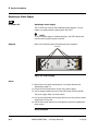
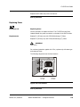
7 Apply power to the CMTS.
The cooling fans should start to turn, and the CMTS should display initial
startup messages on the LCD screen on the front panel. The following
figure shows the location of the LCD.
End of procedure
LCD
NS
FA
0 1 2 3 4 5
RX RX RX RX RX RX
X 0 1
AU FE FE
UP
O
C
N
US
U1 U2 AT
PS PS ST
LCD
Figure 3-6: LCD location
Release 4.3, Standard
ARRIS PROPRIETARY — All Rights Reserved
3-9
3 CMTS Installation
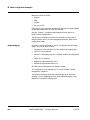
Initial Configuration
The following sequence can be used to start up the ARRIS Cadant C3. This
startup sequence assumes an “out of the box” initial condition.
Prerequisites
The following items must be set up before configuring the CMTS:
Optional Items
Initial Boot Parameters
•
An external DHCP server must be running.
•
An external TFTP server must contain the cable modem configuration
file specified by the DHCP server.
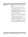
The following items are optional for the initial configuration, but may be
required for normal operation:
•
A ToD server is available for the cable modem.
•
An NTP server is available for the CMTS.
•
A Syslog server is available.
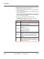
Required boot parameters depend on how the C3 loads its software image.
Table 3-4: Required boot parameters
If the software
image is on…
the C3 flash disk
Required boot parameters are…
none
booting interface (see below)
an external TFTP
server
initial IP address of the booting interface
default gateway IP address to the TFTP server
the 802.1Q VLAN ID if booting over an 802.1Q
VLAN encoded backbone is required
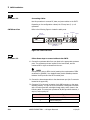
The choice of the booting interface (fa0/0 or fa0/1) also pre-defines
certain bridging behavior of the CMTS. You can reconfigure this behavior,
but from a factory default condition before the system loads it’s code for
the first time (or no startup-configuration on the compact flash disk):
3-10
•
Selecting fa0/0 configures “in-band” behavior. All cable modem and
CPE traffic is directed to fa0/0; you can use either Ethernet port for
managing the CMTS.
•
Selecting fa0/1 configures “out-of-band” behavior. All CPE traffic is
directed to fa0/0. All cable modem traffic is directed to fa0/1. You can
use either Ethernet port for managing the CMTS if “managementaccess” is specified in the interface configuration.
ARRIS PROPRIETARY — All Rights Reserved
11/14/05
C3 CMTS User Guide
Factory Default Network
Settings
Factory default network settings are:
•
IP address is one of:
•
- 10.1.127.120
- 10.1.127.121
- 10.1.127.122
- 10.1.127.123
Subnet mask: 255.255.128.0
•
Gateway address:10.1.0.3
See Appendix F, Factory Defaults for a complete list of factory default
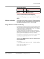
settings.
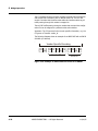
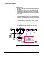
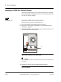
Rear Panel Connectors
Refer to the following diagram when performing this procedure.
DC power
Serial
AC power
FE0
-
Figure 3-7: Rear panel connectors
Perform the following tasks in the order shown.
Procedure 3-4
•
Preparing the Connections, page 3-11
•
Verifying Proper Startup, page 3-12
•
Setting Boot Parameters, page 3-13
•
Configuring an Initial CLI Account, page 3-16
Preparing the Connections
1 Connect the appropriate AC or DC power cables to the CMTS. Do not
power up yet.
2 Connect the RS232 serial cable to the serial port and connect the other end
to a terminal (or PC with a terminal emulation program).
Release 4.3, Standard
ARRIS PROPRIETARY — All Rights Reserved
3-11
3 CMTS Installation
3 Start the console application and set the console configuration to:
•
Port: Com1/Com2, depending on your connection
•
Baud rate: 38400
•
Data: 8 bits
•
Parity: None
•
Stop bit: 1
•
Flow control: None
End of procedure
Procedure 3-5
Verifying Proper Startup
Follow these steps to start the C3 CMTS for the first time.
1 Power on the CMTS and verify that the following status LEDs on the front
panel are illuminated green:
•
FANS
•
PSU1
•
PSU2 (if second power supply is installed)
•
Status
2 Verify that the FE0 and FE1 ports on the back of the CMTS have illuminated
green Link LEDs (for the port that is being used).
3 Wait for the message “Press any key to stop auto-boot...” to appear on the
console, then press any key to stop auto booting before the count reaches
0.
NOTE
Auto booting continues after two seconds.
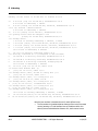
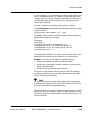
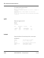
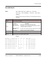
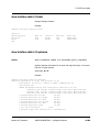
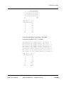
4 At prompt, type help or ? and press Enter to view the different
commands available for boot options.
The first commands you see are user level commands.
CMTS>?
---------------------------------------------------------------Command
Description
---------------------------------------------------------------boot
Boot the CMTS using current boot parameters
bootShow
Display current boot parameters
enable
Enable Supervisor/Factory Level
sysShow
Show system configuration
timeShow
Displays current Date and Time from RTC
3-12
ARRIS PROPRIETARY — All Rights Reserved
11/14/05
C3 CMTS User Guide
dir
vlevel
reboot
help
?
@
>
Show directory of Compact Flash
Set Verbosity Level
Reboot
Display general help or help about a command
Display general help or help about a command
Boot the CMTS using current boot parameters
End of procedure
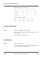
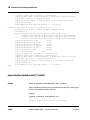
Procedure 3-6
Setting Boot Parameters
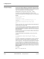
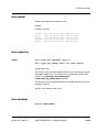
1 Enter privileged mode using the enable command to change the boot
parameters. The first time you enter this mode, there is no password set
and you can enter with no password. Use the setpwd command if a
password is required in the future.
Several more commands are now available. Type ? to see the entire list.
>enable
No supervisor level password set yet
Use "setpwd" command to set password
Supervisor level enabled
>?
---------------------------------------------------------------Command
Description
---------------------------------------------------------------boot
Boot the CMTS using current boot parameters
bootShow
Display current boot parameters
bootCfg
Configure the boot parameters
cf
Select Compact Flash for booting
tftp
Select TFTP for booting
wan
Select FA0/0(WAN) port for network access
mgmt
Select FA0/1(MGMT) port for network access
enable
Enable Supervisor/Factory Level
disable
Disable Supervisor/Factory Level
sysShow
Show system configuration
setTime
Set time in RTC
setDate
Set Date in RTC
timeShow
Displays current Date and Time from RTC
dir
Show direcory of Compact Flash
setpwd
Set password
vlevel
Set Verbosity Level
setVlanId
Set the VLAN tag to be used
vlanEnable
Enable VLAN tagging/stripping as set by setVlanId
vlanDisable
Disable VLAN tagging/stripping
reboot
Reboot
help
Display general help or help about a command
?
Display general help or help about a command
@
Boot the CMTS using current boot parameters
>
Release 4.3, Standard
ARRIS PROPRIETARY — All Rights Reserved
3-13
3 CMTS Installation
2 Decide what Ethernet interface to use for network access, using the
commands wan (to select FE0/0) or mgmt (to select FE0/1).
The bootShow command displays the selected interface as the “Network
port” as shown in the next step.
Most CLI commands refer to the FE0/0 port as fastethernet 0/0.0 and
the FE0/1 port as fastethernet 0/1.0.
If the CMTS has been booting from one interface and you change this
interface using the above commands, for the changed factory default
configuration to take effect, you need to erase the old configuration using
the CLI command “write erase” before entering the boot options. Then,
power cycle the CMTS to re-create the startup configuration based on the
new boot options.
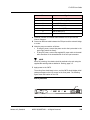
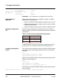
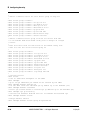
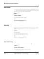
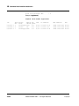
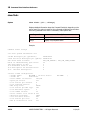
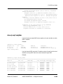
3 Enter bootShow to view the current boot options. (Note that the CMTS
does not show the TFTP server IP address unless BootCfg is selected as
following).
A listing similar to the following displays:
C3>bootShow
*** Current Boot Parameters ***
Boot from
: Compact Flash
Boot file
: C:\2.0.3.12.bin
CMTS IP Address
: 10.1.127.121
CMTS subnet mask
: ffff7f00
Gateway Address
: 10.1.0.3
CMTS Name
: CMTS
Network port
: WAN
Vlan Tagging
: Disabled
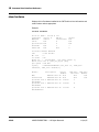
4 If the C3 is to be managed over an 802.1Q VLAN, make the VLAN
assignment so that remote management systems can communicate with
the C3 during the boot process. This is also required if the C3 is configured
to boot using TFTP, since the TFTP transfer might use the VLAN. Use the
vlanEnable and setVlanId commands to set up the VLAN.
C3>vlanEnable
C3>setVlanId 1
C3>bootShow
*** Current Boot Parameters ***
Boot from
: Compact Flash
Boot file
: C:\4.3.0.32.bin
CMTS IP Address
: 10.1.127.121
CMTS subnet mask
: ffff7f00
Gateway Address
: 10.1.0.3
CMTS Name
: CMTS
Network port
: WAN
3-14
ARRIS PROPRIETARY — All Rights Reserved
11/14/05
C3 CMTS User Guide
Vlan Tagging
: Enabled
Vlan Id
: 1 (0x1)
C3>
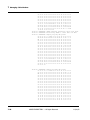
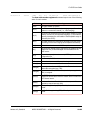
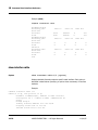
5 To change the above list of boot options, enter bootCfg at the command
prompt. You can change the boot parameters one at a time. Enter the new
value for each parameter in turn to modify them. Then enter bootShow
to review the changes. Set the IP address for the ARRIS Cadant C3 to suit
your network.
>bootCfg
Options:
*[1] Boot from TFTP
[2] Boot from Compact Flash
Select desired option : [2]
Application Image path : [C:\4.3.0.32.bin]
CMTS Ip Address : [10.1.127.121]
CMTS Subnet Mask : [255.255.128.0]
TFTP Server Ip Address : []
Gateway Ip Address : [10.1.0.3]
Saving in non-volatile storage
>>
“Application Image path” is the name of the file and the file path if stored
locally on the compact flash disk that contains the code image to be
loaded. Note that the drive letter C is in UPPER CASE.
“Gateway Ip Address” is the IP address of the default router on the backbone network. The C3 uses this IP address for TFTP server booting.
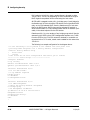
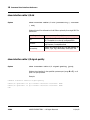
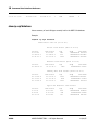
6 Once the boot parameters have been modified as required, boot the
system by entering @ or boot at the prompt.
Once the system is booted, the serial port supports the CLI. When this is
the first time the ARRIS Cadant C3 has been powered up, the CMTS automatically creates all of the required run time files from the specified image
file.
The CMTS loads the image file and comes online.
The following output is representative of that generated on the console
screen during boot and initialization.
*** Current Boot Parameters ***
Boot from
: Compact Flash
Boot file
: C:\4.3.0.32.bin
CMTS IP Address
: 10.1.127.121
CMTS subnet mask
: ffff7f00
Gateway Address
: 10.1.0.3
CMTS Name
: CMTS
Release 4.3, Standard
ARRIS PROPRIETARY — All Rights Reserved
3-15
3 CMTS Installation
Network port
: WAN
Vlan Tagging
: Disabled
Attached TCP/IP interface to sbe0.
Attaching network interface lo0... done.
.
.
.
etc
.
.
.
!
No CLI accounts - Telnet is disabled
!
Please configure a login account with the "cli
account" command
Arris CMTS
C3>
End of procedure
Procedure 3-7
Configuring an Initial CLI Account
You must create at least one CLI account before the CMTS allows telnet
access. Follow these steps to create a CLI account.
1 If you have not done so already, type enable to enter privileged mode.
The prompt changes to a # symbol.
2 Enter the following commands to create an account:
C3# configure terminal
C3(config)# cli account {acctname} password {passwd }
The CMTS creates the account with the specified name and password.
3 Enter the following command to give privileged (enable) access to the
account:
C3(config)# cli account {acctname} enable-password
{enapasswd}
C3(config)# exit
The login password and enable password may be the same if you prefer.
End of procedure
3-16
ARRIS PROPRIETARY — All Rights Reserved
11/14/05
C3 CMTS User Guide
Procedure 3-8
Configuring the Network Time Protocol (optional)
The C3 optionally uses NTP to set its internal clock. You can configure the
NTP server IP address from the CLI using telnet or a serial console once
the application image is running. Follow these steps to configure NTP, if
desired.
1 Log into the CMTS, using the account you created in the previous task.
2 Type enable to enter privileged mode, and then type the enable password
(set in the previous task).
3 Enter the following commands to begin configuring NTP:
C3# config t
C3(config-t)# ntp server {ntp_ip_addr}
4 Create a timezone to specify the time offset from GMT:
C3(config-t)# clock timezone {name}{offset}
Where name is the name of the time zone (any string), and offset is the
offset, in hours, from GMT.
Example: clock timezone EDT -4
5 Exit the global configuration mode by typing exit or end.
6 Confirm the time settings:
C3# show clock
7 Copy the running configuration to the startup configuration:
C3# copy running-config startup-config
C3# write
The CMTS stores the new time settings in non-volatile memory.
NOTE
If NTP is not available, set the internal clock using the clock set
command.
End of procedure
Release 4.3, Standard
ARRIS PROPRIETARY — All Rights Reserved
3-17
3 CMTS Installation
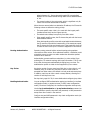
Configuring IP Networking
The C3 applies the CMTS IP address configured in the boot parameters to
the fastethernet interface selected as the boot interface, and to the cable
interface when booting from the default configuration (or when no startupconfiguration file is available). If these settings are not suitable, use this
procedure to specify the IP address information required for normal C3
operation.
You should also specify at least one fastethernet sub-interface to be available for system management; see management-access, page 10-188, for
details.
Configuration Options
The C3 CMTS supports two configuration options:
•
•
Chapter 4, Bridge Operation
IP routing mode—see Chapter 6, IP Routing
bridging (no IP routing) mode—see
Default Bridge Groups
Depending on the boot interface you chose in Setting Boot Parameters,
page 3-13, the C3 pre-configures two bridge groups.
Action
Perform one of the following tasks:
Configuring Bridging Mode, page 3-18
Configuring IP Routing Mode, page 3-19
Procedure 3-9
Configuring Bridging Mode
Follow these steps to configure a different default route.
1 Log into the CMTS.
2 Enter one of the following groups of commands:
a
To assign the management IP address to the fastethernet 0/0.0
(FE0/0) primary sub-interface, enter the following commands:
C3# config terminal
C3(config)# interface fastethernet 0/0
C3(config-if)# ip address {mgmt-ip-addr} {mask}
C3(config-if)# exit
C3(config)# exit
C3# copy running-config startup-config
3-18
ARRIS PROPRIETARY — All Rights Reserved
11/14/05
C3 CMTS User Guide
b
To assign the management IP address to the fastethernet 0/1.0
(FE0/1) primary sub-interface, enter the following commands:
C3# config terminal
C3(config)# interface fastethernet 0/1
C3(config-if)# ip address {mgmt-ip-addr} {mask}}
C3(config-if)# exit
C3(config)# exit
C3# copy running-config startup-config
3 Enter the following commands to set the default gateway IP address:
C3# config terminal
C3(config)# ip default-gateway {gw_ip_addr}
C3(config)# exit
C3# copy running-config startup-config
End of procedure
Procedure 3-10
Configuring IP Routing Mode
Follow these steps to the configure the C3 CMTS for IP routing mode:
1 If IP routing is turned on while a cable subinterface has the same IP
address as a fastethernet interface in the same bridge group, changing to
pure IP routing is not successful. Remove the cable interface IP address or
change the cable interface IP address before turning on IP routing mode.
If pure IP routing with no bridge groups is required, use step c; otherwise,
use steps a and b.
a
IP routing with bridge-group memberships:
C3# config terminal
C3(config)# ip routing
b
Configure the default route if necessary:
C3# config terminal
C3(config)# ip route 0.0.0.0 0.0.0.0 {route}
Where
route
= IP address of the default route (or route of last resort)
Release 4.3, Standard
ARRIS PROPRIETARY — All Rights Reserved
3-19
3 CMTS Installation
c
True IP routing, removing bridge-group memberships:
C3# config terminal
C3(config)# ip routing
C3(config)# interface fastethernet 0/0.0
C3(config-if)# no bridge-group
C3(config-if)# interface cable 1/0.0
C3(config-if)# no bridge-group
C3(config-if)# interface fastethernet 0/1.0
C3(config-if)# no bridge-group
C3(config-if)# interface cable 1/0.1
C3(config-if)# no bridge-group
C3(config-if)# exit
C3(config)# exit
2 Set the IP address of the cable interface:
C3(config)# interface cable 1/0.0
C3(config-if)# ip address {cbl_ip} {subnet}
The cbl_ip address may not be in the same subnet as the management
IP address.
3 Configure the DHCP relay (this is required for a cable modem to register
when the CMTS is in IP routing mode):
C3(config-if)# ip dhcp relay
4 Cable helper address is mandatory for IP routing cable sub-interfaces that
are running DHCP relay.
C3(interface)# cable helper-address {ipaddr}
C3(interface)# exit
5 Enter the following commands to save the routing configuration:
C3(config)# exit
C3# copy running-config startup-config
End of procedure
3-20
ARRIS PROPRIETARY — All Rights Reserved
11/14/05
C3 CMTS User Guide
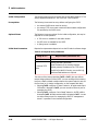
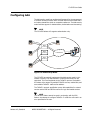
Configuring the Cable
Interfaces
Use this procedure to configure and connect the cable upstreams and
downstream.
Appendix B shows some example configurations.
Appendix F shows the factory default configuration. The factory default
configuration has the downstream in a shutdown condition so the C3 is in
a passive state by default.
Requirements
Connect the downstream and any upstreams in use before performing this
procedure.
Cable Connections
The following diagram shows the locations of the cable connections on the
rear panel of the C3 CMTS.
Cable 1/0
Downstream
FE0/0
Cable 1/0
Upstreams 0-5
Figure 3-8: Rear cable connections
Action
Procedure 3-11
Perform the following tasks in the order shown.
•
Configuring Downstream Parameters, page 3-21
•
Configuring Upstream Parameters, page 3-22
•
Enabling the Interfaces, page 3-24
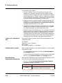
Configuring Downstream Parameters
Follow these steps to configure the downstream cable interface.
1 Connect a PC to the CMTS, using either the serial port or the Ethernet
interface (telnet connection).
2 Log into the CMTS.
3 Type enable to get into privileged mode, and then type the enable
password.
Release 4.3, Standard
ARRIS PROPRIETARY — All Rights Reserved
3-21
3 CMTS Installation
4 Use the following commands to begin cable interface configuration:
C3# conf t
C3(config)# interface cable 1/0
5 Set the downstream frequency (in Hz) using the following command:
C3(config-if)# cable downstream frequency {freq}
Example: cable downstream frequency 501000000
6 Set the power level (in dBmV) using the following command:
C3(config-if)# cable downstream power-level {pwr}
Set the power level to match the parameters assigned by the plant
designer. Example: cable downstream power-level 51
7 (optional) Set the DOCSIS mode using one of the following commands:
C3(config-if)# cable mac-mode {docsis}
C3(config-if)# cable mac-mode {euro-docsis}
8 (optional) Set the downstream modulation type using one of the following
commands:
C3(config-if)# cable downstream modulation 64qam
C3(config-if)# cable downstream modulation 256qam
9 Proceed to Configuring Upstream Parameters, page 3-22.
End of procedure
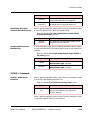
Procedure 3-12
Configuring Upstream Parameters
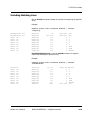
Follow these steps to configure each upstream cable interface. The parameter us refers to the upstream interface ID, 0 to 5, corresponding to
upstreams RX0 through RX5 on the back of the C3 CMTS.
1 Set the upstream mac-mode using one of the following commands:
C3(config-if)# cable mac-mode {docsis}
C3(config-if)# cable mac-mode {euro-docsis}
2 Set the upstream channel type, using the following command:
C3(config)if)# cable upstream {us} channel-type {type}
Where type is one of: tdma, atdma, tdma&atdma, or scdma.
3-22
ARRIS PROPRIETARY — All Rights Reserved
11/14/05
C3 CMTS User Guide
NOTE
All channel types for a particular channel must match the modulation
profile selected for that channel. If any channel type does not match the
modulation profile, the C3 disables that channel until you correct either
the channel type or modulation profile.
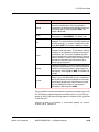
3 Set the physical upstream channel width (in Hz) using the following
command:
C3(config-if)# cable upstream {us} channel-width
{width}
The channel width specified must be a DOCSIS-standard upstream
channel width.
ATDMA: 6400000 (6.4 MHz)
ATDMA and TDMA: 3200000 (3.2 MHz), 1600000 (1.6 MHz), 800000
(800 KHz), 400000 (400 KHz), or 200000 (200 KHz).
SCDMA: 1600000 (1.6 MHz), 3200000 (3.2 MHz), or 6400000
(6.4 MHz).
Example: cable upstream 2 channel-width 3200000
4 Set the physical upstream channel frequency (in Hz) using the following
command:
C3(config-if)# cable upstream {us} frequency {freq}
The valid frequency range is 5000000 (5 MHz) to 42000000 (42 MHz)
for North American DOCSIS, and 5000000 (5 MHz) to 65000000
(65 MHz) for EuroDOCSIS.
Example: cable upstream 2 frequency 25000000
5 Assign the modulation profile to an upstream using the following
command:
C3(config-if)# cable upstream {us} modulation-profile
{n}
Where n is a modulation profile index, 0 to 5.
The factory default modulation profile for each upstream is profile 1. This
profile uses QPSK and is the safest profile to use to get modems online.
6 Set the input power level (the target receive power set during the DOCSIS
ranging process) using the following command:
C3(config-if)# cable upstream {us} power level {power}
Release 4.3, Standard
ARRIS PROPRIETARY — All Rights Reserved
3-23
3 CMTS Installation
The valid power range depends on the channel width; the range -4 to 14
is valid for all channel widths. See cable upstream power-level,
page 10-239 for individual ranges.
Example: cable upstream 2 power level 0
7 Repeat steps 2 through 5 for each upstream that you need to configure.
Proceed to Enabling the Interfaces, page 3-24.
End of procedure
Procedure 3-13
Enabling the Interfaces
Follow these steps to enable the cable interfaces.
1 Enable an upstream cable interface using the following commands:
•
For physical interfaces: no cable upstream [n] shutdown
•
For logical interfaces: no cable upstream [n.c] shutdown
Repeat this command for each configured upstream or logical channel.
2 Enable the downstream cable interface using the following command:
C3(config-if)# no shutdown
The CMTS is now ready to acquire and register cable modems. To display
the current CMTS configuration, use the show running-config
command.
End of procedure
3-24
ARRIS PROPRIETARY — All Rights Reserved
11/14/05
4
Bridge Operation
Topics
Page
Bridging Features
3
Bridge Concepts
4
Bridge Binding
14
IP Addressing
16
Attaching Bridge Groups
18
Incoming Traffic Allocation to a Sub-Interface
19
The C3 CMTS supports IP bridging and routing modes of operation. This
chapter describes bridging mode.
For more information, see:
Chapter 5, Providing Multiple ISP Access for information about using
bridge groups to separate traffic and provide cable modem access to
multiple ISPs.
Chapter 6, IP Routing for information about the C3’s optional IP
routing mode.
Release 4.3, Standard
ARRIS PROPRIETARY — All Rights Reserved
4-1
4 Bridge Operation
Terms and Abbreviations
The following are terms and abbreviations used in this chapter.
booting interface — The Fast Ethernet interface specified in the boot
options. Use the wan command to specify fastethernet 0/0, or mgmt to
specify fastethernet 0/1.
bridge binding — Bridge binding maps a sub-interface A with VLAN tag
a to a sub-interface B with VLAN tag b; packets with tag a arriving on subinterface A are immediately bridged to sub-interface B with tag b, and vice-
versa. No other layer 2 bridging rules are followed.
bridge group — A group of sub-interfaces that may forward (bridge)
packets to other sub-interfaces in the group. There is no interaction
between bridge groups at the MAC level.
default cm subinterface — A designated sub-interface used for cable
modem traffic until the cable modem receives an IP address from a DHCP
server.
default cpe sub-interface — A designated sub-interface, used as a
source sub-interface for CPE traffic when it has no VLAN tag or other
explicit mapping (using the map-cpes command or VSE method).
native tagging — Cisco routing nomenclature; sub-interfaces using
native tagging do not actually tag packets transmitted from that sub-interface, but the tag number is still associated with the sub-interface for
internal processing purposes.
routing sub-interface — A sub-interface that supports layer 3 routing.
The default sub-interface behavior is layer 2 bridging.
sub-interface — A logical subdivision of a physical interface. The C3
supports up to 64 sub-interfaces per physical interface.
VLAN tag — The VLAN ID, used to associate a cable modem or CPE with
a sub-interface. The tag can be specified either in 802.1Q VLAN encapsulated packets; or in native mode, in the cable modem’s VSE.
VSE — Abbreviation for Vendor-Specific Encoding. The VSE is a TLV,
stored in the cable modem configuration file, that specifies the VLAN ID
used to associate the cable modem’s CPE with a sub-interface. During
modem registration, this information is passed to the CMTS allowing the
CMTS to map traffic through the modem to a nominated cable subinterface
with a matching native VLAN tag.
4-2
ARRIS PROPRIETARY — All Rights Reserved
11/14/05
C3 CMTS User Guide
Bridging Features
The factory default operating mode of the C3 is bridging mode.
In general, normal bridging operation should not be assumed.
•
In no configuration does bridging occur between the two Fast Ethernet
interfaces.
•
Bridging between the FastEthernet interfaces and the cable interfaces
is controlled by:
-
•
the selection of the boot option network interface when no
startup-configuration file exists
- the selection of the boot option network interface when upgrading
from release 2.0 to release 4.0 software
- an existing startup-configuration file; the configuration overrides
the boot options
IP forwarding occurs even though the C3 is running in bridging mode.
•
IP forwarding between bridge groups is turned off by default for security reasons.
•
IP forwarding between bridge groups (IP traffic allowed to leave a
bridge group) may be turned on using the command ip l2-bg-to-bgrouting in the interface specification of any interface attached to the
bridge group.
•
Static routes may be defined using the ip route command for:
-
C3 management traffic
the DHCP relay agent
IP forwarding between bridge groups (using ip l2-bg-to-bgrouting)
NOTE
In bridging mode, other cable modem and CPE traffic should be bridged
and static routes should not be used.
NOTE
Define a default gateway for the C3 using the command ip
default-gateway, page 10-142 from the CLI. A default gateway has the
same purposes and restrictions as a static route.
Release 4.3, Standard
ARRIS PROPRIETARY — All Rights Reserved
4-3
4 Bridge Operation
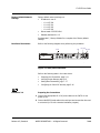
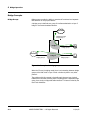
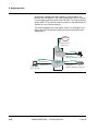
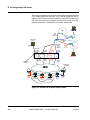
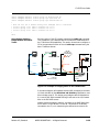
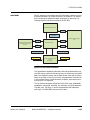
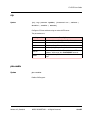
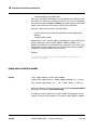
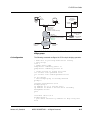
Bridge Concepts
Bridge Groups
Bridge groups provide the ability to operate self contained and separate
MAC domains in one physical device.
A bridge group is defined as a group of interfaces attached to a layer 2
bridge or a common broadcast domain.
BACKBONE
fastethernet 0/0.0
bridge-group 1
bridge 1
cable
bridge-group 1
PC
cable
bridge-group 0
PC
BACKBONE
fastethernet 0/1.0
bridge-group 0
bridge 0
Figure 4-1: Example of a bridge group
When the C3 runs in bridging mode, there is no interaction between bridge
groups at the MAC level or layer 2 level—whether by ARP or any other
protocol.
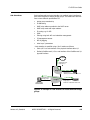
The problem with this concept is that although there are two physical
FastEthernet interfaces, allowing each to be assigned to a separate bridge
group, there is only one physical cable interface. This issue is solved by the
use of sub-interfaces.
4-4
ARRIS PROPRIETARY — All Rights Reserved
11/14/05
C3 CMTS User Guide
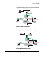
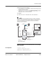
Sub-Interfaces
Sub-interfaces split a physical interface into multiple logical interfaces to
allow more flexibility in creating bridge groups. This allows each sub-interface to have different specifications for:
•
bridge group membership
•
IP addressing
•
DHCP relay address provided to the DHCP server
•
DHCP relay mode and helper address
•
IP routing e.g. for RIP
•
IGMP
•
Filtering using both ACL and subscriber management
•
C3 management access
•
802.1Q tagging
•
other layer 3 parameters
A sub-interface is specified using a “dot” notation as follows:
•
Cable 1/0.2 is a sub-interface of the physical interface cable 1/0.
•
Similarly FastEthernet 0/1.5 is a sub-interface of the FastEthernet 0/1
physical interface.
BACKBONE
fastethernet 0/0.0
bridge-group 1
bridge 1
fastethernet 0/1.0
bridge-group 0
bridge 0
Cable Operator
DHCP/TFTP/ToD
cable 1/0.1
bridge-group 1
PC
default cpe subinterface cable 1/0.0
cable 1/0.0
Modem
bridge-group 0
default cm subinterface cable 1/0.0
Figure 4-2: Example of a sub-interface to access different bridge
groups
Release 4.3, Standard
ARRIS PROPRIETARY — All Rights Reserved
4-5
4 Bridge Operation
The C3 allows one sub-interface to be defined that is not a member of any
defined bridge group. This interface is marked as “Management Access
Only” in the “show interface” output—and as the description suggests, this
interface can only be used to manage the CMTS.
BACKBONE
fastethernet 0/0.0
bridge-group 0
PC
bridge 0
Management
cable 1/0.0
Modem
bridge-group 0
default cpe interface cable 1/0.0
default cm interface cable 1/0.0
fastethernet 0/1.0
Figure 4-3: Example of a “Management Access Only” interface
The big issue with sub-interfaces is the decision making process of how
traffic is mapped from the physical interface to a sub-interface for these
different specifications to have an effect. This issue is discussed later in
this chapter.
Default Bridge Operation
The factory default mode of operation of the C3 is bridging mode. In this
mode, the C3 has two bridge groups. Without the use of the keyed bridgegroup licensing feature, each of the two factory defined bridge groups can
support a maximum of 2 sub-interfaces; only one may be a cable subinterface. Without the bridge group license, up to the maximum of 64
subinterfaces may be created and used in static “ip routing” mode but they
cannot be connected to a bridge group if the limit of two subinterfaces per
bind group is exceeded. Once the bridge-group license is purchased, up to
10 sub-interfaces per bridge group and up to 64 bridge groups is allowed.
The Additional VLAN/Bridge Group License (Product ID 713869) extends
the limits to 64 bridge groups, each of which supports up to 10 sub-interfaces with no restriction on the number of cable sub-interfaces. Contact
4-6
ARRIS PROPRIETARY — All Rights Reserved
11/14/05
C3 CMTS User Guide
your ARRIS representative for ordering information and other details. See
the next chapter for more details about advanced bridging, even if you are
not purchasing this license.
BACKBONE
fastethernet 0/0
bridge-group 0
PC
bridge 0
cable 1/0
Modem
bridge-group 0
default cpe subinterface cable 1/0.0
default cm subinterface cable 1/0.0
fastethernet 0/1
bridge-group 1
shutdown
bridge 1
cable 1/0.1
bridge-group 1
shutdown
Figure 4-4: Illustration of the default bridge configuration
For more information, see:
Selecting the Bridge Group
Configuration
Release 4.3, Standard
•
the CLI commands ip default-gateway and ip route for their relevance in bridging mode
•
Appendix B, for sample bridging network configurations.
The above bridge group configurations may be changed:
•
from the boot options using the wan or mgmt command to select the
network interfaces labeled FE0/0 and FE0/1 respectively before a
startup-configuration file is created on first power up. This can occur
by deleting the existing startup-configuration file (using the write
erase command) then power cycling, or the first time the C3 is
powered up. In either case a default startup-configuration will be
created based on the selected boot options network interface.
•
by specification from the CLI after the Cadant C3 has been booted
(with this configuration subsequently saved to the startup-configuration)
ARRIS PROPRIETARY — All Rights Reserved
4-7
4 Bridge Operation
Fast Ethernet 0/0 as the
Boot Options Network
Interface
This is the factory default mode of operation of the C3.
In this mode, the C3:
•
pre-assigns interface fastethernet 0/0.0 to bridge group 0
•
pre-assigns interface cable 1/0.0 to bridge group 0
•
pre-assigns interface fastethernet 0/1.0 to bridge group 1, and shuts
down the interface
•
pre-assigns cable 1/0.1 to bridge group 1, and shuts down the interface
•
sets “default cm subinterface cable 1/0.0”
•
sets “default cpe subinterface cable 1/0.0”
•
carries the boot option specified IP address forward into a factory
default configuration as the fastethernet 0/0 IP address, and also
applies this IP address to the cable 1/0.0 sub-interface (this default
configuration can be overwritten from the CLI).
BACKBONE
fastethernet 0/0
no shutdown
boot IP address
bridge-group 0
PC
bridge 0
cable 1/0
Modem
bridge-group 0
default cpe subinterface cable 1/0.0
default cm subinterface cable 1/0.0
fastethernet 0/1
bridge-group 1
shutdown
bridge 1
cable 1/0.1
bridge-group 1
shutdown
Figure 4-5: Illustration of the factory default configuration
NOTE
All the above settings may be changed at the CLI. For example, you can
override the “management” IP address by a running-configuration
4-8
ARRIS PROPRIETARY — All Rights Reserved
11/14/05
C3 CMTS User Guide
specification and subsequently save it to the startup-configuration. You
could also assign that IP address to the FastEthernet 0/1.0 sub-interface.
The following is an example network configuration and the CLI commands
required to set it up.
10.99.99.1
INTERNET
CABLE
OPERATOR
DHCP
route add 10.99.98.0 via
10.99.99.253
ROUTER
10.99.98.1
SWITCH
10.99.98.0
network
PC
fastethernet 0/0.0
bridge-group 0
ip address 10.99.99.253
bridge 0
CMTS
fastethernet 0/1.0
bridge-group 1
shutdown
DEFAULT ROUTE
10.99.98.1
DHCP SERVER
10.99.99.1
bridge 1
cable 1/0.0
bridge-group 0
ip address 10.99.99.253
ip address 10.99.98.253 secondary
default cpe subinterface cable 1/0.0
default cm subinterface cable 1/0.0
10.99.99.0
network
Modem
DEFAULT ROUTE
10.99.99.1
DHCP SERVER
10.99.99.1
cable 1/0.1
bridge-group 1
shutdown
Figure 4-6: Example of a bridging network configuration
! if the following is to be pasted to the command line
! then paste from supervisor mode
configure terminal
!
! bridges already set up from factory default
! bridge 0
! bridge 1
!
interface fastethernet 0/0.0
ip address 10.99.99.253 255.255.255.0
bridge-group 0
no ip l2-bg-to-bg-routing
!
interface fastethernet 0/1.0
bridge-group 1
! no IP address required
! do not need running either
Release 4.3, Standard
ARRIS PROPRIETARY — All Rights Reserved
4-9
4 Bridge Operation
shutdown
!
interface cable 1/0.0
bridge-group 0
no shutdown
no cable upstream 0 shutdown
no cable upstream 0.0 shutdown
ip address 10.99.99.253 255.255.255.0
ip address 10.99.98.253 255.255.255.0 secondary
!
! Update giaddr with 10.99.99.253 for cable-modem
! update giaddr with 10.99.98.253 for host
ip dhcp relay
no ip dhcp relay information option
cable dhcp-giaddr policy
! unicast ALL dhcp to 10.99.99.1
cable helper-address 10.99.99.1
exit
!
interface cable 1/0.1
bridge-group 1
shutdown
!
! nothing to do here in this case
exit
exit
Fast Ethernet 0/1 as the
Boot Options Network
Interface
Selecting the fastethernet 0/1 interface as the boot options network interface, when there is no existing startup-configuration file, pre-assigns the
bridge groups to force all cable modem traffic to the fastethernet 0/1 interface, and all CPE traffic to the fastethernet 0/0 interface. This results in
“out of band” operation of the C3.
Selecting FE01 as the booting interface:
•
pre-assigns interface fastethernet 0/0.0 to bridge group 1
•
pre-assigns interface cable 1/0.0 to bridge group 0
•
pre-assigns interface fastethernet 0/1.0 to bridge group 0
•
pre-assigns cable 1/0.1 to bridge group 1
•
sets “default cm subinterface cable 1/0”
•
sets “default cpe subinterface cable 1/0.1”
•
carries the boot option specified IP address forward into a factory
default configuration as the fastethernet 0/1 IP address.
Again, all the above settings may be changed at the CLI.
4-10
ARRIS PROPRIETARY — All Rights Reserved
11/14/05
C3 CMTS User Guide
The following diagram shows data flow in the C3 when fastethernet 0/1 is
the boot interface.
Backbone
fastethernet 0/0.0
bridge-group 1
ip l2-bg-to-bg-routing
bridge 1
cable 1/0.1
PC
bridge-group 1
default cpe subinterface cable 1/0.0
fastethernet 0/1.0
boot IP address
bridge-group 0
bridge 0
Cable Operator
DHCP/TFTP/TOD
cable 1/0.0
Modem
bridge-group 0
default cm subinterface cable 1/0.0
Figure 4-7: Data flow when FastEthernet 0/1 is the boot interface
In this example, DHCP relay must be turned on in the cable 1/0.1 subinterface specification if CPE DHCP is to be served by a DHCP server on the
fastethernet 0/1 sub-interface (MGMT port).
In addition, ip l2-bg-to-bg-routing must be enabled on the fastethernet
0/1.0 sub-interface for the CPE DHCP Renew to succeed. The DHCP Relay
function relays the Renew from cable 1/0.1 to the fastethernet 0/1.0 subinterface. The DHCP Renew ACK received at the fastethernet 0/1.0 subinterface must be routed across bridge groups to cable 1/0.1; and the ACK
function is not destined for cable 1/0.1 but it is destined for the CPE. Since
the ACK is not relayed by the DHCP Relay function and must be routed by
the C3, the fastethernet 0/1.0 must have ip l2-bg-to-bg-routing activated.
For more information, see the network examples in Appendix B.
Decide what is Management
Traffic
Software releases prior to v3.0 locked the user into accepting cable
modem traffic as “management” traffic.
This software release allows the user to decide what is management
traffic:
Release 4.3, Standard
•
CMTS traffic only, or
•
CMTS and cable modem traffic
ARRIS PROPRIETARY — All Rights Reserved
4-11
4 Bridge Operation
By defining the default cable sub-interface for modem traffic to be
different than the default for CPE traffic, modem traffic can be removed
from the bridge group that contains the CPE traffic. This requires that the
modem DHCP, TFTP, and ToD servers be present on the fastethernet 0/1
interface as in the following example.
The following diagram shows the default, version 2.0-compatible, operating mode. CMTS management traffic and cable modem traffic share
bridge group 0.
Backbone
fastethernet 0/0.0
bridge-group 1
bridge 1
cable 1/0.1
PC
bridge-group 1
default cpe subinterface cable 1/0.0
fastethernet 0/1.0
boot IP address
bridge-group 0
bridge 0
Cable Operator
DHCP/TFTP/TOD
cable 1/0.0
Modem
bridge-group 0
default cm subinterface cable 1/0.0
Figure 4-8: Default, V2.0 compatible, operating mode
4-12
ARRIS PROPRIETARY — All Rights Reserved
11/14/05
C3 CMTS User Guide
The following diagram shows bridge group 0 restricted to carrying CMTS
management traffic, and bridge group 1 used for all cable modem and CPE
traffic.
Backbone
Cable Operator
DHCP/TFTP/TOD
fastethernet 0/0.0
bridge-group 1
bridge 1
cable 1/0.1
bridge-group
PC
default cpe subinterface cable 1/0.0
default cm subinterface cable 1/0.0
fastethernet 0/1.0
no bridge group
CMTS
Management
Only
bridge 0
cable 1/0.0
bridge-group 0
Modem
Figure 4-9: Example of Bridge group 0
The following diagram shows bridge group 0 unused, and bridge group 1
used for all cable modem traffic. CMTS management traffic is restricted to
a management-only sub-interface. This sub-interface is configured with
the CMTS IP address and has management access enabled.
Backbone
Cable Operator
DHCP/TFTP/TOD
fastethernet 0/0.0
bridge-group 1
bridge 1
cable 1/0.1
bridge-group 1
PC
default cpe subinterface cable 1/0.0
default cm subinterface cable 1/0.0
fastethernet 0/1.0
no bridge group
bridge 0
CMTS
Management
Only
cable 1/0.0
bridge-group 0
Modem
Figure 4-10: Example of Bridge group 1
Release 4.3, Standard
ARRIS PROPRIETARY — All Rights Reserved
4-13
4 Bridge Operation
The final example shows CMTS management traffic on a managementonly sub-interface, as before, and cable modem traffic and CPE traffic on
separate bridge groups.
Backbone
fastethernet 0/0.0
bridge-group 1
fastethernet 0/1.0
no bridge-group 0
bridge 1
cable 1/0.1
PC
bridge-group 1
default cpe subinterface cable 1/0.0
Cable Operator
Management
fastethernet 0/1.1
Cable Operator
DHCP/TFTP/TOD
bridge-group 0
encap dot1q 22
bridge 0
cable 1/0.0
Modem
bridge-group 0
default cm subinterface cable 1/0.0
Figure 4-11: Example of CMTS management traffic
Bridge Binding
Bridge binding provides a direct link between a tagged cable sub-interface
and a tagged FastEthernet sub-interface.
The cable sub-interface may use a native tag (used with VSE or mapcpes) or may use normal 802.1Q tagging. A FastEthernet interface must
use 802.1Q tagging for bridge binding purposes.
Using a bridge bind specification can further reduce the broadcast domain.
This is especially relevant in the cable interface where the downstream and
upstream are treated as separate interfaces in the bridge group. A layer 2
broadcast received at the cable interface is re-broadcast on all interfaces
attached to the bridge group. This includes the cable downstream interface if the command l2-broadcast-echo is present. This characteristic of
the cable interface can be a security risk. Use of the bridge bind is one
method provided in the C3 to restrict such broadcasts propagating into the
cable downstream or to unwanted Ethernet interfaces.
4-14
ARRIS PROPRIETARY — All Rights Reserved
11/14/05
C3 CMTS User Guide
The following diagram shows the effect of bridge binding on upstream
Layer 2 broadcasts:
INTERFACE 0/0
INTERFACE 0/0
CABLE
DOWNSTREAM
BROADCAST
CABLE
DOWNSTREAM
OPTIONAL
BROADCAST
( l2-broadcast-echo )
BRIDGE
BROADCAST
BRIDGE
CABLE UPSTREAM
CABLE UPSTREAM
BROADCAST
BROADCAST
INTERFACE 0/1
BROADCAST
INTERFACE 0/1
CABLE UPSTREAM
BRIDGE BIND TO
INTERFACE 0/0
Figure 4-12: Bridge binding on US Layer 2 broadcast
Bridge binding may be used in another way.
If all CPE traffic is allocated to a cable sub-interface (how this is done is
described following), it is possible to further restrict this traffic to 802.1Q
encoded traffic by specifying an encapsulation command on the cable subinterface. This would allow a number of 802.1Q VLANs to terminate on the
cable sub-interface.
Implementation of the multiple encapsulation commands under the cable
and fastethernet interfaces are illegal and will be rejected by the CLI.
Release 4.3, Standard
ARRIS PROPRIETARY — All Rights Reserved
4-15
4 Bridge Operation
This problem is shown in the following figure. The following example
shows the legal use of the bridge bind command to implement the same
configuration as that defined as the problem in the following figure.
PROBLEM
INTERFACE 0/0
encapsulation dot1q 11
encapsualtion dot1q 22
PROBLEM:
Which VLANS to map the cable
interface VLANS to:
11?
22?
BRIDGE
SOLUTION
INTERFACE 0/0
CABLE
DOWNSTREAM
bridge 1 bind cable 1/0 1 fa 0/0 11
bridge 1 bind cable 1/0 2 fa 0/0 22
Solves this issue
CABLE UPSTREAM
encapsulation dot1q 100 native
encapsulation dot1q 1
encapsualtion dot1q 2
802.1q encoded data
INTERFACE 0/1
PROBLEM:
Illegal multiple encapsulation
specifications
CABLE
DOWNSTREAM
BRIDGE 1
CABLE UPSTREAM
encapsulation dot1q 100 native
802.1q encoded data
INTERFACE 0/1
Note: Traffic allocated to cable interface using
VSE encoding with tag 100 (eg. the "native"
option is used)
Figure 4-13: Example of legal use of the bridge bind command
IP Addressing
A bridge does not require an IP address to operate. The C3 however can
be managed over an IP network and thus must be assigned a valid IP
address for management purposes.
Due to the nature of operation of a bridge, any interface in either of the
two default bridges on the C3 may be assigned an IP address and this IP
address may be accessed again from any interface in the same bridge
group for management purposes. You can also assign the same IP address
to both a cable and fastethernet sub-interface; this allows continued
management access if one of the interfaces is shut down for any reason.
4-16
ARRIS PROPRIETARY — All Rights Reserved
11/14/05
C3 CMTS User Guide
CMTS Management
CMTS Management
Management
Systems
Management
Systems
IP address a.b.c.d
OK but not
recommended
Recommended
PC
PC
bridge 0
bridge 0
IP address a.b.c.d
Modem
Modem
bridge 1
bridge 1
Recommended
bridge 0
PC
IP address a.b.c.d
Management
Systems
bridge 1
Modem
CMTS Management
Figure 4-14: Example of IP addressing
This “management” IP address is normally assigned from the serial
console and is programmed in the startup-configuration file found on the
compact flash disk.
Do not confuse the management IP address with the IP address set in the
boot options. The C3 uses the IP address specified in boot options and the
booting Fast Ethernet interface only if a TFTP server based boot is
required—the IP address provides enough IP information to allow a TFTP
server-based boot to occur. This boot option specified address can be
copied to a factory default startup configuration as detailed in previous
sections of this document but can be changed from the CLI.
As the above diagram shows, you can assign the management IP address
to a cable sub-interface. This is not recommended. If the cable interface
is shutdown, you cannot manage the C3 from the network. Serial console
access is not affected.
Replacing a Legacy Bridging
CMTS
Release 4.3, Standard
If the C3 is to be used in a system where only one IP address is allocated
to the CMTS, and C3 DHCP relay is also required, the cable interface must
have an IP address for DHCP relay to operate. In this case, in bridging
mode, the cable interface can be allocated the same IP address as the
“management” Fast Ethernet interface in the same bridge group.
ARRIS PROPRIETARY — All Rights Reserved
4-17
4 Bridge Operation
Attaching Bridge Groups
Since a bridge group operates at the MAC layer, it can bridge IP protocols.
However, the bridge group forms an isolated MAC domain and only has
knowledge of devices connected to it. The bridge group can recognize IP
protocols when it is attached to the C3’s IP stack.
Attaching a bridge group to the IP stack requires at least one sub-interface
in the bridge group to have an IP address, and for that sub-interface to be
operationally up.
When a bridge group is attached, whether the C3 is configured for IP
routing or bridging mode, IP packets entering the bridge group (whose
MAC destination address is an interface on the C3) can now be passed to
the C3’s IP stack and IP-level communication between bridge groups can
occur.
This communication is not always desirable, as it degrades bridge group
isolation. Therefore, this function is turned off by default for every subinterface created from the CLI. Use the sub-interface command ip l2-bgto-bg-routing to allow such IP traffic to leave a bridge group and be
passed to the IP stack. In some cases, this is a required step for DHCP to
be successful.
In the following example:
•
modem traffic is isolated to bridge group 0—the same bridge group
that the DHCP server is connected to
•
modem DHCP succeeds, even if DHCP relay is not turned on
Now consider the CPE devices:
4-18
•
All CPE traffic is isolated to bridge group 1
•
DHCP relay must be activated on cable 1/0.1 for DHCP from the CPE
to reach the DHCP server connected to fastethernet 0/1.0
•
DHCP relay requires that cable 1/0.1 be given an IP address.
•
The DHCP ack and offer from the DHCP server will be received at
fastethernet 0/1.0
•
DHCP relay will forward the offer or ack back to the relaying interface—the cable 1/0.1 sub-interface.
•
The ACK to a CPE DHCP renew is not captured by the DHCP Relay
function (being addressed to the CPE and not the cable 1/0.1 subinterface) but must be forwarded across bridge groups to the CPE
device. For the ACK to be forwarded across bridge groups, ip l2-bg-
ARRIS PROPRIETARY — All Rights Reserved
11/14/05
C3 CMTS User Guide
to-bg-routing again must be specified on fastethernet 0/1.0. No
other sub-interface needs an ip l2-bg-to-bg-routing specification.
CPE traffic is still securely restricted to bridge group 1.
Provisioning
Server
Internet
Internet gateway
205.2.3.254/24
10.6.0.2/24
10.6.0.1/24
0/1.0
tag=none
Bridge
Group
0
ip l2-bg-to-bg- routing
1/0.0
tag=none
Bridge
Group
1
Cadant C3
1/0.0
tag=1
native
10.6.0.0/24
HFC
Internet
Customer
Internet
Customer
Network = 205.2.3.0/24
Gateway = 205.2.3.254
Figure 4-15: Example of attaching bridge groups
Incoming Traffic Allocation to a Sub-Interface
As detailed above, the concept of bridge groups and sub-interfaces is very
powerful but hinges on how traffic arriving by a physical interface is allocated to a sub-interface by the Cadant C3.
In summary:
•
Fastethernet sub-interfaces use 802.1q VLAN tags
•
Cable sub-interfaces use:
-
Release 4.3, Standard
VSE encoding
the map-cpes command
the default cpe subinterface
the cable modem vpn command
ARRIS PROPRIETARY — All Rights Reserved
4-19
4 Bridge Operation
If a mapped frame has an 802.1Q tag, the C3 verifies that the tag is
correct for the mapped sub-interface; if the tag does not match, the
C3 drops the frame.
Fastethernet Interface
802.1Q VLAN tags are used to allocate incoming packets to FastEthernet
sub-interfaces with matching encapsulation dot1q specifications.
Only one FastEthernet sub-interface per physical interface may have no
encapsulation configured. All untagged traffic is directed to this subinterface. If a second FastEthernet sub-interface is defined with no VLAN tag,
the sub-interface configuration is ignored and a CLI message warns of the
incomplete configuration and informs the user which is the current
untagged sub-interface.
Cable Interface
Default Mapping of CM to a
Sub-Interface
If a global specification default cm subinterface cable X/Y.Z is present
in the C3 global configuration, then all modem traffic received is mapped
to the nominated cable sub-interface until the cable modem receives an IP
address from DHCP and moves to its correct sub-interface. Note this is a
default mapping and will be overridden by any modem IP address based
mapping once the modem has an IP address.
If no default is specified, the C3 automatically assigns cable 1/0.0 as the
default sub-interface.
Cable Modem IP Traffic
When a cable modem receives a DHCP Ack, the C3 inspects the assigned
IP address to determine which sub-interface that the cable modem should
be assigned to. The C3 maps all subsequent IP traffic from that cable
modem to a sub-interface that has the same subnet specified.
If no subset match can be found in any cable sub-interface specification,
the IP packet is mapped to the default cable sub-interface.
CPE Traffic
Upstream CPE traffic may be allocated to cable sub-interfaces using:
•
the cable modem vpn command
•
VSE encoding
•
map-cpes specification
•
default cpe subinterface specification
If a mapped frame has an 802.1Q tag, the C3 verifies that the tag is correct
for the mapped sub-interface; if the tag does not match, the C3 drops the
frame.
Again, one cable sub-interface may have no encapsulation specification.
All other cable sub-interfaces must have an encapsulation specification in
the form:
4-20
•
encapsulation dot1q X or
•
encapsulation dot1q X native
ARRIS PROPRIETARY — All Rights Reserved
11/14/05
C3 CMTS User Guide
VSE and 802.1Q Native
Tagging
The combination of native tagging and VSE encoding is one method that
allows CPE traffic to be mapped to a cable sub-interface.
A cable sub-interface with native tagging means that:
•
all traffic received at this interface will be internally tagged by the C3
before being passed to the bridge group to which the sub-interface is
a member.
•
Traffic leaving the bridge group via this natively tagged sub-interface
will be tagged as it leaves the C3.
Contrast this behavior with the 802.1Q tagging on a FastEthernet subinterface where all traffic leaving the C3 is tagged if the FastEthernet subinterface has an 802.1q tag specification.
Thus native tagging is a means to identify traffic that has arrived at a
particular cable sub-interface. This native tagging can also be used to map
CPE traffic to a cable sub-interface.
During registration with the CMTS, all modems send a Vendor ID TLV,
identifying the modem vendor to the CMTS in addition to any information
received by the modem in the configuration file sent to the modem.
A cable modem configuration file may have added to it Vendor Specific
Encoding (VSE) that can be used to send proprietary information to a
vendor’s modems. If a modem receives such information and this information has a vendor_id that does not match that of the modem vendor, the
modem ignores this information. Thus a single configuration file may
contain vendor specific information for multiple vendors without any
impact on modems without a matching vendor_id. This is the original
purpose of this DOCSIS feature.
Regardless of whether the modem has a matching vendor_id to the configuration file specified vendor specific information or not, the modem must
under DOCSIS specifications send all such received information to the
CMTS during registration.
This means that the C3 receives all vendor specific information that the
modem received in its configuration file.
NOTE
The C3 ignores all other vendor-specific information; for example, the C3
ignores a Thomson vendor_id.
This mechanism thus provides a method to transfer information from a
modem configuration file and the provisioning systems to the C3 during
modem registration.
Release 4.3, Standard
ARRIS PROPRIETARY — All Rights Reserved
4-21
4 Bridge Operation
The C3 inspects all vendor specific encoding received during registration
and accepts VSE information with an ARRIS vendor ID. This TLV can
contain a number that identifies what cable sub-interface native tag all
traffic passing through this modem is mapped to.
Thus all CPE traffic passing through a modem that received this configuration file can be mapped to a particular cable sub-interface.
Important: The C3 ignores all other vendor specific information; e.g. the
C3 ignores a Thomson vendor_id.
The following diagram shows an example of an ARRIS VSE with a VPN ID
of 000Bh (11 decimal)
.
Vendor Specific Encoding
43 09
08 03 00 00 CA
Vendor ID
01 02 00 0B
VPN ID
Figure 4-16: Example of ARRIS VSE with a VPN ID of 000Bh
4-22
ARRIS PROPRIETARY — All Rights Reserved
11/14/05
C3 CMTS User Guide
The following diagram shows an example of a configuration file containing
such VSE information - a VSE tag of 11 decimal is shown:
Figure 4-17: Example configuration file with VSE information
If no VSE messages are received from a modem during registration, traffic
from any attached CPE devices will be allocated using any cable modem
vpn specification, map-cpes specification or default cpe subinterface
specification. If no default is specified, the C3 automatically assigns cable
1/0.0 as the default sub-interface.
Example: — Let us first review quickly how standard non-DOCSIS aware
DHCP servers allocate IP addresses.
DHCP servers use the giaddr IP address—the relaying IP address—to indicate from which address pool an IP address should be allocated from. It is
thus important that the relaying address or the giaddr address be a meaningful address on the relaying device.
Defining cable sub-interfaces for CPE devices allows this to happen. Each
cable sub-interface can have a different IP address specification with the
IP address being used to populate the giaddr field as determined by the
DHCP specifications of this sub-interface.
configure terminal
bridge 13
Release 4.3, Standard
ARRIS PROPRIETARY — All Rights Reserved
4-23
4 Bridge Operation
cable 1/0.0
! for modem only
bridge-group 0
ip address 10.99.99.1 255.255.255.0
ip DHCP relay
cable helper-address 10.0.0.1 cable-modem
cable dhcp-giaddr primary
cable 1/0.11
! for cpe with IP address
bridge-group 1
! define ip address
ip address 10.11.0.1 255.255.255.0
ip DHCP relay
cable helper-address 10.0.0.1 host
cable dhcp-giaddr primary
! for CPE traffic via modem with VSE tag = 11
encapsulation dot1q 11 native
cable 1/0.13
! for cpe layer 2 forwarding
! for CPE traffic via modem with VSE tag = 13
bridge-group 13
encapsulation dot1q 13 native
map-cpes
The map-cpes command allows re-direction of CPE traffic attached to a
modem to a specified cable sub-interface.
Once a modem is allocated an IP address, the modem is mapped to any
cable sub-interface that has a matching subnet. Thus if modems are allocated to different subnets, they can be mapped by the C3 to different cable
sub-interfaces.
If a map-cpes specification is in place in the cable sub-interface that the
modem is allocated to, all incoming CPE frames arriving via this modem
are allocated to the specified cable sub-interface.
Example:
configure terminal
bridge 11
interface fastethernet 0/0.1
bridge-group 11
encapsulation dot1q 111
interface cable 1/0.0
! for modem only
bridge-group 0
ip address 10.99.99.1 255.255.255.0
4-24
ARRIS PROPRIETARY — All Rights Reserved
11/14/05
C3 CMTS User Guide
ip dhcp relay
cable helper-address 10.0.0.1 cable-modem
cable dhcp-giaddr primary
map-cpe cable 1/0.11
interface cable 1/0.11
! for cpe bridging
bridge-group 11
! accept 802.1q tagged frames only
encapsulation dot1q 11
Default Mapping of CPE to a
Sub-Interface
If a the global specification default cpe subinterface cable X/Y.Z is
present in the Cadant C3 global configuration, the C3 maps all CPE traffic
from any modem that cannot be mapped to any sub-interface to the this
nominated default cable sub-interface and hence to a default cable VPN.
Note this is a default mapping and is overridden by any VSE or map-cpes
based mapping.
If no other form of mapping is used then the default mapping is cable
1/0.0 (the default cable sub-interface).
Cable Modem VPN
The standard modem configuration file VSE mechanism to map a modem’s
CPEs to a particular subinterface has been augmented by the addition of
command-line facilities, the cable modem VPN command.
When cable modem X.X.X registers, traffic to and from all devices behind
modem X.X.X will be mapped to the cable subinterface which has VLANTAG configured. This command is very useful when modem configuration
file modifications are not possible or the number of cable modems is small.
If the cable modem in online when this command is issued, no changes
will take place until the cable modem is rebooted.
CPE 802.1Q Traffic
The C3 uses 802.1Q tags for verification and binding purposes.
If a mapped incoming frame has an 802.1Q tag, the C3 verifies that the
tag is correct for the mapped sub-interface; if the tag does not match, the
C3 drops the frame.
If the incoming frame has an 802.1Q header but this frame is mapped to
a cable sub-interface by a map-cpes specification, the mapped sub-interface must have a matching 802.1Q tag for this frame to be accepted.
In either case, the C3 passes the frame to the bridge group this cable subinterface is a member of, bridging the frame to other sub-interfaces
assigned to the bridge group.
Release 4.3, Standard
ARRIS PROPRIETARY — All Rights Reserved
4-25
4 Bridge Operation
Frames bridged to fastethernet sub-interfaces are treated as follows:
•
If the fastethernet sub-interface has an encapsulation specification,
the C3 encodes the frame with this tag and the frame leaves the CMTS
with an 802.1Q encoding.
•
If the fastethernet sub-interface does not have an encapsulation specification, the C3 strips the 802.1Q header and the frame leaves the
CMTS untagged.
Note that the cable interface 802.1Q tag can be different from the fastethernet interface 802.1Q tag.
Example:
configure terminal
bridge 11
!
fastethernet 0/0.1
bridge-group 11
encapsulation dot1q 111
cable 1/0.0
! for modem only
bridge-group 0
ip address 10.99.99.1 255.255.255.0
ip dhcp relay
cable helper address 10.0.0.1 cable-modem
cable dhcp-giaddr primary
map-cpes cable 1/0.11
cable 1/0.11
! for cpe bridging
bridge-group 11
! accept 802.1q tagged frames only
encapsulation dot1q 11
bridge bind
The bridge bind can be used to bind a cable sub-interface directly to a
FastEthernet sub-interface as detailed earlier. A bridge-bind can also be
used with VSE and 802.1Q native encoding.
The following example shows CPE traffic mapped to a cable sub-interface
using VSE encoding. All traffic is bridged and VLAN tagged on exit from the
bridged fastethernet sub-interface.
A series of bridge-bind specifications also adds support for 802.1Q tagging
to this cable sub-interface cable 1/0.13. This facility has been used by a
customer to provide tiered services inside the VPN formed by the combination of the mapping of CPE traffic to this cable sub-interface and the use
4-26
ARRIS PROPRIETARY — All Rights Reserved
11/14/05
C3 CMTS User Guide
of the command encapsulation dot1q xx encrypted-multicast to
provide downstream broadcast privacy to CPE using this cable-sub-interface.
Example:
Bridge 0
Bridge 1
bridge 2
int fa 0/0.0
! management ip address
ip address 10.1.0.1 255.255.255.0
bridge-group 0
int fa 0/0.13
bridge-group 2
! no ip address
encapsulation dot1q 13
int cable 1/0.0
! for modem only
ip address 10.99.99.1 255.255.255.0
bridge-group 0
ip dhcp relay
cable helper-address 10.0.0.1 cable-modem
map-cpes ca 1/0.13
int cable 1/0.13
bridge-group 2
! for cpe layer 2 forwarding
encapsulation dot1q 13 native
! create VPN privacy
encapsulation dot1q 13 encrypted-multicast
exit
! all traffic ariving at cable 1/0.13
! check for tag 4, bridge to fa 0/0.13
! and tag with 44 before leaving
bridge 2 bind cable 1/0.13 4 fastethernet 0/0.13 44
! all traffic ariving at cable 1/0.13
! check for tag 5, bridge to fa 0/0.13
! and tag with 55 before leaving
bridge 2 bind cable 1/0.13 5 fastethernet 0/0.13 55
Release 4.3, Standard
ARRIS PROPRIETARY — All Rights Reserved
4-27
4 Bridge Operation
Transparent bridging
One way the C3 applies VLAN tags on a subinterface is with the encapsulation dot1q tag command explained above. In addition, it is now
also possible to configure the subinterface so that other tag values will also
“map” to that subinterface. Use the following command:
encapsulation dot1q allow {tag[-tag] [,tag]}+
It is possible to have multiple encapsulation dot1q allow
commands to fully specify which VLAN tags terminate on the subinterface.
Example:
interface cable 1/0.9
bridge-group 9
encapsulation dot1q9
encapsulation dot1q 9 encrypted multicast !! if
requried
encapsulation dot1q allow 101-199, 801-899
encapsulation dot1q allow 1200, 1205, 1599
end
The above sets Cable 1/0.9 to use tag 9 as before but also allows tags 101199, 801-899, 1200, 1205 and 1599.
To ensure transparent bridging, all subinterfaces in a bridge-group should
have the same encapsulations configured. Tagged packets arriving on one
sub-interface destined for transmission out the other will then be passed
with the tag “intact.”
Overlapping VLAN tag ranges are not allowed on different subinterfaces of
the same physical interface.
To remove allowed tags from a subinterface, use the no form of the
command:
no encapsulation dot1q allow 101-199, 801-899
no encapsulation dot1q allow 1-4094 !! removes all
‘allows’
The “primary” encapsulation (eg. encapsulation dot1q n) cannot be
removed in this manner but must be explicitly removed as before. The
“allows” are just that — other tags which are also handled by the interface.
To ping a CPE which is in a transparently-bridged bridge-group, the C3
must have an ARP entry for the CPE. However, if the C3 doesn’t know the
appropriate VLAN tag, the ARP will never reach the CPE. To overcome this,
the ping command has been extended to allow the operator to enter the
initial-arp-vlan-tag.
For example:
ping 1.2.3.4 arp-vlan 18
4-28
ARRIS PROPRIETARY — All Rights Reserved
11/14/05
C3 CMTS User Guide
would cause the ARP for 1.2.3.4 to be tagged with 18. If the C3 already
had an ARP table entry for 1.2.3.4, then the entry would be used and no
ARP would be generated.
Traffic allocation—summary
The C3 processes incoming cable modem packets as follows:
•
Before the cable modem receives an IP address, the C3 assigns all
incoming packets from that cable modem to the default CM sub-interface.
•
When the cable modem receives a DHCP Ack, the C3 inspects the
assigned IP address and uses that to assign further cable modem
packets to a sub-interface.
The C3 processes incoming CPE packets in the following order:
1 Check for the existence of the cable modem VPN command. If it exists,
map all CPEs to the specified VLAN tag; then go to step 5.
2 Check for modem based VSE encoding and map the traffic to a cable subinterface with an encapsulation tag matching the VSE tag allocated to the
modem; then go to step 5.
3 Check the sub-interface the attached modem is assigned to for a mapcpes specification; if found, map the CPE traffic to the specified cable subinterface, then go to step 5.
4 Check for default mapping of CPE to a cable sub-interface using the
default cpe-subinterface specification and map CPE traffic to this cable
sub-interface; then go to step 5.
5 Check for CPE-based 802.1Q VLAN tagging against the mapped subinterface VLAN specification (specified under the cable sub-interface or
using a bridge-bind specification). Bridge the frame with a matching tag
and drop the frame if:
•
the VLAN specification does not exist, or
•
the VLAN specification exists but does not match the frame
6 Check that the sub-interface exists and is active. If not active or does not
exist then drop the data frame.
This testing is performed for modem-sourced frames and CPE-sourced
frames arriving via a cable modem.
The only test above that is relevant to a cable modem is the test allowing
modems to be allocated to cable sub-interfaces based on the allocated
modem IP address.
Release 4.3, Standard
ARRIS PROPRIETARY — All Rights Reserved
4-29
4 Bridge Operation
4-30
ARRIS PROPRIETARY — All Rights Reserved
11/14/05
5
Providing Multiple ISP
Access
Topics
Page
Open Access
1
Cable-VPN Implementation
3
Using the Modem IP Address to allocate CPE to a VPN
5
Using a Modem Configuration File to Allocate CPEs to a VPN
11
Open Access
Open access is an operating concept that allows a subscriber to choose
from a number of ISPs. On a practical networking side, open access
requires that a subscriber CPE device attached to a cable modem be given
a default route that is not associated with any of the cable modem plant.
Typically this default route would be the gateway IP address of the chosen
ISP’s edge router.
Open access support is limited in the C3 to bridging mode only. In IP
routing mode, the C3 requires that the CPE device have a default route of
the nearest router—in IP routing mode, the nearest router is the C3 cable
interface. The C3 as a whole has only has one default route and all CPE
traffic would have to use this route thus not allowing an ISP edge router
to be selected as the subscriber CPE device default.
Release 4.3, Standard
ARRIS PROPRIETARY — All Rights Reserved
5-1
5 Providing Multiple ISP Access
The following example shows an open access system implemented with a
C3 in bridging mode with three ISPs. Two of the ISPs issue their own IP
address; one ISP requires the cable operator to issue CPE IP addresses. In
each case, the router option passed to the CPE device is that of the ISP
gateway routers and is independent of the cable modem plant.
ISP BLUE
DHCP Server
ISP
ISP
router
205.2.3.254
Provisioning
Server
ISP BLUE
router
3.56.7.9
ISP
BLUE
Fast Ethernet
links
ProCurve
802.1Q
trunk
red/blue
/internet
10.6.0.2/24
10.6.0.1/24
fa 0/1.0
tag=none
Bridge
Group
0
Bridge
Group
1
ca 1/0.0
tag=none
ip l2-bg-bgrouting
fa 0/0.1
tag=22
fa 0/0.0
tag=11
Bridge
Group
2
ca1/0.2
tag=2
native
ca 1/0.1
tag=1
native
ISP RED
router
204.3.4.5
ISP
RED
fa 0/0.2
tag=33
Bridge
Group
3
ISP RED
DHCP Server
ca 1/0.3
tag=3
native
all modems in
10.6.0.0/24
HFC
ISP RED
router
204.3.4.5
ISP
router
205.2.3.254
ISP RED
router
204.3.4.5
ISP
router
205.2.3.254
ISP BLUE
router
3.56.7.9
ISP BLUE
router
3.56.7.9
Figure 5-1: Example of an Open Access system
5-2
ARRIS PROPRIETARY — All Rights Reserved
11/14/05
C3 CMTS User Guide
Cable-VPN Implementation
VLANs, combined with the ability to create native VLANs on the cable subinterfaces may be used to create virtual private networks. In the above
example, each subscriber would in effect be provisioned by the cable operator to join one of three virtual private networks, each virtual private
network being connected to a single ISP.
Subscribers assigned to an ISP in the above example by the provisioning
system can have complete downstream privacy from subscribers assigned
to other ISPs, as follows:
•
Downstream broadcast privacy
•
Downstream unicast privacy
•
Upstream unicast/broadcast privacy
The following discussion refers to a native VLAN with downstream privacy
enabled as a cable-VPN.
All physical interfaces may have up to 64 sub-interfaces defined allowing
up to 63 native VLANs to be defined per Cadant C3.
interface cable 1/0.0
bridge-group 1
encapsulation dot1q 33 native ! create native vlan
encapsulation dot1q 33 encrypted-multicast ! add
downstream privacy
exit
When this is done, the native VLAN provides downstream privacy for its
members and is described following as a cable-VPN.
Traffic arriving on one interface with tag X will be bridged out to the other
interface with tag X. Effectively, this allows 4094 VLANs. The number of
bridge groups supported remains at 64.
Example:
configure terminal
interface cable 0/0.1
encapsulation dot1q
encapsulation dot1q
bridge-group 1
interface cable 1/0.1
encapuslation dot1q
encapsulation dot1q
bridge-group 1
end
1 !! as per normal
allow 1-4094
1 !! as per normal
allow 1-4094
Cable-VPNs may use IP routing or bridging modes, or both, or may even
decode or encode 802.1Q VLANS inside the cable-VPNs as required.
Release 4.3, Standard
ARRIS PROPRIETARY — All Rights Reserved
5-3
5 Providing Multiple ISP Access
The provisioning systems may assign subscribers to a cable-VPN by the IP
address assigned to the modem the subscriber uses or alternatively by the
configuration file the modem receives from the provisioning system.
Assignment to a cable-VPN by modem IP address allows legacy provisioning systems to be compatible with the ARRIS Cadant C3 cable-VPN
facility. No configuration file modifications are required. This method
restricts the number of supported cable-VPNs to 31 (one cable modem
sub-interface for every mapped CPE sub-interface) and the DHCP server
must support a method to assign a modem an IP address outside the
subnet of the giaddr (relay address) in the modem DHCP discover.
Assignment to cable-VPNs by a configuration file allows the full number of
63 cable-VPNs to be implemented but in this case, the DHCP server must
support assignment of DHCP options (modem configuration file) to individual modems.
In either case, CPE are mapped to a specific cable sub-interface with
native VLAN tagging with the properties of this cable sub-interface defining
the properties of the cable-VPN.
•
A layer 2 (bridged) cable sub-interface allows all layer 2 protocols
inside the cable-VPN.
•
When IP routing is active, a layer 3 sub-interface with ip sourceverify subif specified only allows IP protocols inside the VPN and only
source addresses within the subnets associated with the cable subinterface (primary subnet and up to 15 secondary subnets per subinterface).
•
A hybrid layer 2 + 3 sub-interface allows both IP and layer 2 protocols.
All cable-VPN sub-interfaces are bridged using bridge groups or IP routed
to FastEthernet sub-interfaces.
The C3 FastEthernet sub-interfaces use 802.1Q to propagate the bridged
cable-VPN traffic into the operator backbone by maintaining privacy using
802.1Q tagging.
For Open Access purposes, we only consider bridged cable sub-interfaces
as discussed above.
5-4
ARRIS PROPRIETARY — All Rights Reserved
11/14/05
C3 CMTS User Guide
Using the Modem IP Address to allocate CPE to a VPN
This example uses the C3 map-cpes command.
Modems are issued IP addresses in different subnets. Modems are mapped
to cable sub-interfaces by matching the assigned modem IP address to a
matching cable sub-interface subnet. Modem cable-sub-interfaces in turn
have a map-cpes specification that maps all CPE traffic (for CPE attached
to these modems) to the cable sub-interface specified by the map-cpes
command.
Items to note in the following example:
Release 4.3, Standard
•
Select the no ip routing mode of operation. This allows the CPE
default route or gateway to be specified by the cable operator in the
DHCP options given to the CPE and to be different to any IP addressing
on the C3. Normally the CPE default route should be directed to the
gateway router of the ISP the CPE is to be provisioned to use.
•
All CPE traffic is bridged thus layer 2 protocols are supported.
•
A default cable-VPN has been created for un-provisioned subscribers.
This cable-VPN maps to an Ethernet VLAN directing un-provisioned
subscribers to a specific subnet and backbone VLAN allowing access
only to the provisioning web server.
•
A default modem cable sub-interface has been created. All modem
DHCP discover broadcasts are mapped to this cable sub-interface. This
cable sub-interface is a member of bridge group 9. A sub-interface of
the MGMT port is configured as a member of this bridge group and has
a VLAN tag of 999, the same VLAN tag of the DHCP server.
•
Once modems have an IP address, modem traffic is allocated to cable
sub-interfaces by modem source IP address match to sub-interface
subnet. All modem sub-interface are members of bridge group 9 and
are thus connected to the DHCP server using tag 999. These sub-interfaces contain the map-cpes specifications re-directing CPE traffic to
other (or the same) cable sub-interfaces and hence cable-VPNs.
ARRIS PROPRIETARY — All Rights Reserved
5-5
5 Providing Multiple ISP Access
The following shows the network diagram for this example.
ISP 2
VLAN 999
ISP 1
ISP 3
Cable Operator
DHCP 1
Edge Router
VLAN Switch
PC
PC
3
N
A
VL
VLAN Switch
N
LA
1
11
Provisioning
web server
PC
VLA
N
Edge Router
222
Edge Router
33
V
WAN
MGMT
VPN 11
VPN 22
CMTS
VPN 33
VLAN 888
CABLE
Modem assigned to "ISP 1" by
IP address, CPE traffic assigned
by map-cpes
VPNs bridged
to VLANS
VPN 44
Default VPN for
unprovisioned
subscribers
PC
Figure 5-2: Example network diagram
5-6
ARRIS PROPRIETARY — All Rights Reserved
11/14/05
C3 CMTS User Guide
The following shows how the C3 bridges data flowing through the above
network.
ip l2 bg-to-bg-routing
ISP 1
bridge 1
CABLE 1/0.0
ISP1 PC
FA0/0.0
ISP 2
bridge 2
CABLE 1/0.2
ISP2 PC
FA0/0.2
bridge 3
ISP 3
CABLE 1/0.3
FA0/0.3
ISP3 PC
bridge 9
FA0/1.0
CABLE 1/0.10
CABLE 1/0.11
CABLE 1/0.12
CABLE 1/0.13
Modem
Cable Operator
DHCP 1
FA0/1.2
bridge 4
CABLE 1/0.4
Unprovisioned
PC
Provisioning
web server
forward
Figure 5-3: Bridging data flow through the C3
Configuration
Run the following as a script on a factory default C3 configuration:
!
conf t
!
! remove the factory default assignments
!
! remove bridges 0 and 1 so no sub-interfaces are attached
no bridge 0
no bridge 1
int ca 1/0
!
! remove any previous ip addresses from the cable interface
no ip address 10.99.99.253 255.255.255.0
exit
! remove the cable 1/0.1 subinterface
! as factory defined but not going to be used
no int ca 1/0.1
!
Release 4.3, Standard
ARRIS PROPRIETARY — All Rights Reserved
5-7
5 Providing Multiple ISP Access
no ip routing
!
! set default subinterface for cm and cpe taffic
! before cm has an IP address
default-cm-subinterface cable 1/0.10
! catch any unknown CPE and direct to
! the provisioning web server
default-cpe-subinterface cable 1/0.4
!
! Define the bridges we will use
! for ISP1 traffic
bridge 1
! for ISP2 traffic
bridge 2
! for ISP3 traffic
bridge 3
! for provisioning server traffic
bridge 4
! bridge 9 used for cm dhcp discover
! and management access to CMTS
! all cm will have access to this bridge group no
! matter what ip address they end up with
bridge 9
!
int fa 0/0.0
description ISP1
! no ip address
bridge-group 1
encapsulation dot1q 111
no ip l2-bg-to-bg-routing
exit
!
int fa 0/0.2
description ISP2
! no ip address
bridge-group 2
encapsulation dot1q 222
no ip l2-bg-to-bg-routing
exit
!
int fa 0/0.3
description ISP3
! no ip address
bridge-group 3
encapsulation dot1q 333
no ip l2-bg-to-bg-routing
exit
!
interface fa 0/1.0
description Management
ip address 10.99.99.2 255.255.255.0
! NOTE: CMTS management can only occur from this VLAN
encapsulation dot1q 999
management-access
bridge-group 9
ip l2-bg-to-bg-routing
! ip address should be in subnet of DHCP server
5-8
ARRIS PROPRIETARY — All Rights Reserved
11/14/05
C3 CMTS User Guide
! this is also the CMTS management address
!
! DHCP server should have static routes added
! for each CPE subnet with this address as the gateway
! e.g.
!
route add 10.1.0.0 mask 255.255.255.0 10.99.99.2
!
route add 10.2.0.0 mask 255.255.255.0 10.99.99.2
!
route add 10.3.0.0 mask 255.255.255.0 10.99.99.2
! so that CPE DHCP ofer and ack can be routed back to
! the appropriate bridge group and hence CPE device
! Note: dhcp relay must be active in all CPE bridge
! groups for this to happen and only DHCP will be routed
exit
!
interface fa 0/1.2
description Provisioning
! ip address should be a subnet
! of provisioning web server
ip address 10.88.88.2 255.255.255.0
encapsulation dot1q 888
no management-access
bridge-group 4
no ip l2-bg-to-bg-routing
exit
!
interface cable 1/0.0
description ISP1_CPE
ip address 10.1.0.1 255.255.0.0
! Note: up to 15 secondary IP addresses can be added
! for non contigous ISP subnets
no management-access
! set up dhcp relay for CPE devices
! must have dhcp relay active in each bridge group
! for dhcp to be forwarded across the bridge groups
! to the dhcp server in bridge-group 9
ip dhcp relay
cable helper address 10.99.99.1
no ip dhcp relay information option
! native tagging required for internal processing
encapsulation dot1q 1 native
! turn on downstream broadcast privacy
encapsulation dot1q 1 encrypted-multicast
bridge-group 1
no ip l2-bg-to-bg-routing
exit
!
interface cable 1/0.2
description ISP2_CPE
ip address 10.2.0.1 255.255.0.0
no management-access
ip dhcp relay
cable helper address 10.99.99.1
no ip dhcp relay information option
encapsulation dot1q 2 native
! turn on downstream broadcast privacy
encapsulation dot1q 2 encrypted-multicast
bridge-group 2
Release 4.3, Standard
ARRIS PROPRIETARY — All Rights Reserved
5-9
5 Providing Multiple ISP Access
no ip l2-bg-to-bg-routing
exit
!
interface cable 1/0.3
description ISP3_CPE
ip address 10.3.0.1 255.255.0.0
no management-access
ip dhcp relay
cable helper address 10.99.99.1
no ip dhcp relay information option
encapsulation dot1q 3 native
! turn on downstream broadcast privacy
encapsulation dot1q 3 encrypted-multicast
bridge-group 3
no ip l2-bg-to-bg-routing
exit
!
interface cable 1/0.4
description UNPROVISIONED_CPE
! ip address should be in the subnet of the
! provisioning server
ip address 10.4.0.1 255.255.0.0
no management-access
ip dhcp relay
cable helper address 10.99.99.1
no ip dhcp relay information option
encapsulation dot1q 4 native
! turn on downstream broadcast privacy
ecnapsulation dot1q 4 encrypted-multicast
bridge-group 4
no ip l2-bg-to-bg-routing
exit
!
interface cable 1/0.10
description modem_default
! default for cm devices before they have IP address
ip address 10.77.77.1 255.255.255.0
no management-access
encapsulation dot1q 10 native
bridge-group 9
ip address 10.77.77.1 255.255.255.0
no management-access
! set up dhcp relay for cm
ip dhcp relay
cable dhcp-giaddr primary
cable helper-address 10.99.99.1
no ip dhcp relay information option
! map attached CPE to the provisioning server
! if a cm is stil lusing this subinterface
! then cm has not been provisioned yet
map-cpes cable 1/0.4
!
exit
!
interface cable 1/0.11
description modem_isp1
! for cm devices for ISP 1 once cm has IP address
5-10
ARRIS PROPRIETARY — All Rights Reserved
11/14/05
C3 CMTS User Guide
ip address 10.11.0.1 255.255.0.0
encapsulation dot1q 11 native
bridge-group 9
ip dhcp relay
cable dhcp-giaddr primary
cable helper-address 10.99.99.1
no management-access
! map all cpe traffic
map-cpes cable 1/0.1
exit
!
interface cable 1/0.12
description modem_isp2
! for cm devices for ISP 2 once cm has IP address
ip address 10.12.0.1 255.255.0.0
encapsulation dot1q 12 native
bridge-group 9
ip dhcp relay
cable dhcp-giaddr primary
cable helper-address 10.99.99.1
no management-access
map-cpes cable 1/0.2
exit
!
interface cable 1/0.13
description modem_isp3
! for cm devices for ISP 3 once cm has IP address
ip address 10.13.0.1 255.255.0.0
encapsulation dot1q 13 native
bridge-group 9
ip dhcp relay
cable dhcp-giaddr primary
cable helper-address 10.99.99.1
no management-access
map-cpes cable 1/0.3
exit
!
interface cable 1/0.0
! Get rf running
! not no rf configuration here so check the factory
! defaults are ok
no cable upstream 0 shutdown
no cable upstream 1 shutdown
no shutdown
no management-access
! no ip address as sub-interface is not used
exit
!
exit
Using a Modem Configuration File to Allocate CPEs to a VPN
This example uses the Cadant C3 Vendor Specific Encoding in the modem
configuration files to map CPE attached to modems to specific cable subinterfaces and hence to specific cable-VPNs and backbone 802.1Q VLANs.
Release 4.3, Standard
ARRIS PROPRIETARY — All Rights Reserved
5-11
5 Providing Multiple ISP Access
The following example:
•
Uses fewer (one only) cable sub-interfaces for modems than the mapcpes method
•
Uses VSE encoding to map CPE traffic to cable sub-interfaces with
native VLAN specifications (cable-VPN) and hence to bridge-groups
and hence to Ethernet sub-interfaces and hence to Ethernet backbone
802.1Q VLANS.
Items to note in the following example:
•
A default cable-VPN has been created for un-provisioned subscribers.
Modems given a configuration file with a VSE encoding of 44 will force
attached CPE devices to the backbone 802.1Q VLAN with a tag of 888.
This Ethernet VLAN connects to the provisioning web server.
•
A default modem cable sub-interface has been created. All modem
traffic before an IP address is allocated to the modem is mapped to
this cable sub-interface. This cable sub-interface is a member of bridge
group 9. A sub-interface of the MGMT port is configured as a member
of this bridge group and has a VLAN tag of 999. As there are no subinterfaces defined with matching subnets to that allocated for
modems, all modem traffic will remain mapped to this interface.
ISP 2
ISP 1
ISP 3
Edge Router
Cable Operator
DHCP 1
Edge Router
PC
PC
PC
VLA
N
Edge Router
VLAN Switch
N
A
VL
VLAN Switch
AN
VL
Provisioning
web server
WAN
MGMT
CMTS
CABLE
VPN
VPN
VPN
VLAN
VPNs bridged
to VLANS
Modem assigned to "ISP 1" by
configuration file, CPE traffic assigned
by VSE coding in configuration file
Default VPN for
unprovisioned
subscribers
PC
Figure 5-4: Diagram of network used in this example
5-12
ARRIS PROPRIETARY — All Rights Reserved
11/14/05
C3 CMTS User Guide
ip l2 bg-to-bg-routing
ISP 1
bridge 1
CABLE 1/0.0
ISP1 PC
FA0/0.0
ISP 2
bridge 2
CABLE 1/0.2
ISP2 PC
FA0/0.2
bridge 3
ISP 3
CABLE 1/0.3
FA0/0.3
ISP3 PC
bridge 9
CABLE 1/0.10
Modem
FA0/1.0
Cable Operator
DHCP 1
FA0/1.2
bridge 4
Provisioning
web server
CABLE 1/0.4
Unprovisioned
PC
Figure 5-5: How the C3 bridges data in the example
Configuration
As can be seen following the level of configuration required is lower than
the map-cpes method.
Notable differences are:
Release 4.3, Standard
•
All modems are now contained in the one IP subnet. This requires that
the DHCP server must support the specification of DHCP options per
reserved address.
•
The encapsulation “native” commands in cable sub-interfaces 0.1
through 1/0.3 must match the VSE tagging. If no match is found, the
CPE traffic will be mapped to the default cable 1/0.4 sub-interface and
be bridged to the provisioning web server.
•
Again option 82 processing is turned off but may be turned on again
if an option 82 aware DHCP server is to be used.
ARRIS PROPRIETARY — All Rights Reserved
5-13
5 Providing Multiple ISP Access
Factory default C3
configuration
Run the following as a script on a factory default C3 configuration:
!
conf t
! remove bridges 0 and 1 so no sub-interfaces are attached
no bridge 0
no bridge 1
!
int ca 1/0
! remove any previous IP addresses from the cable interface
no ip address 10.99.99.253 255.255.255.0
exit
! remove the cable 1/0.1 subinterface -- not used
no int ca 1/0.1
!
no ip routing
!
! set default subinterface for cm taffic before
! cm has an IP address
default cm subinterface cable 1/0.10
default cpe subinterface cable 1/0.4
!
! Define the bridges we will use for CPE trafic
bridge 1
bridge 2
bridge 3
bridge 4
bridge 9
!
int fa 0/0.0
! description ISP1_WAN
encapsulation dot1q 111
bridge-group 1
exit
!
int fa 0/0.2
! description ISP2_WAN
encapsulation dot1q 222
bridge-group 2
exit
!
int fa 0/0.3
! description ISP3_WAN
encapsulation dot1q 333
bridge-group 3
exit
!
interface fa 0/1.0
! description MANAGEMENT
! ip address should be in subnet of DHCP server
ip address 10.99.99.2 255.255.255.0
management-access
encapsulation dot1q 999
bridge-group 9
ip l2-bg-to-bg-routing
exit
!
5-14
ARRIS PROPRIETARY — All Rights Reserved
11/14/05
C3 CMTS User Guide
interface fa 0/1.2
! description PROVISIONING_SERVER
! ip address should be subnet of provisioning web server
ip address 10.88.88.2 255.255.255.0
encapsulation dot1q 888
no management-access
bridge-group 4
exit
!
interface cable 1/0.0
! description ISP1_CPE
ip address 10.1.0.1 255.255.0.0
no management-access
! set up dhcp relay for CPE devices
ip dhcp relay
cable dhcp-giaddr primary
cable helper-address 10.99.99.1
no ip dhcp relay information option
! VSE tagging
! all cm with VSE tag of 11 will cause all attached
! CPE to be mapped to this interface
encapsulation dot1q 11 native
! turn on VPN
encapsulation dot1q 11 encrypted-multicast
bridge-group 1
exit
!
interface cable 1/0.2
! description ISP2_CPE
! for CPE devices for ISP2
ip address 10.2.0.1 255.255.0.0
no management-access
ip dhcp relay
cable dhcp-giaddr primary
cable helper-address 10.99.99.1
no ip dhcp relay information option
encapsulation dot1q 22 native
encapsulation dot1q 22 encrypted-multicast
bridge-group 2
exit
!
interface cable 1/0.3
! description ISP3_CPE
! for CPE devices for ISP3
ip address 10.3.0.1 255.255.0.0
no management-access
ip dhcp relay
cable dhcp-giaddr primary
cable helper-address 10.99.99.1
no ip dhcp relay information option
encapsulation dot1q 33 native
encapsulation dot1q 33 encrypted-multicast
bridge-group 3
exit
!
interface cable 1/0.4
Release 4.3, Standard
ARRIS PROPRIETARY — All Rights Reserved
5-15
5 Providing Multiple ISP Access
! description UNPROVISIONED_CPE
! for CPE devices for unprovisioned subscribers
ip address 10.4.0.1 255.255.0.0
no management-access
ip dhcp relay
cable dhcp-giaddr primary
cable helper-address 10.99.99.1
no ip dhcp relay information option
encapsulation dot1q 44 native
encapsulation dot1q 44 encrypted-multicast
bridge-group 4
exit
!
interface cable 1/0.10
! default for cm devices
! all cm will remain on this interface
bridge-group 9
ip address 10.77.77.1 255.255.255.0
no management-access
! set up dhcp relay for cm
! note: dhcp relay is not really required as DHCP bcast
! would be bridged to the DHCP server network
! via bridge group 9
ip dhcp relay
cable dhcp-giaddr primary
cable helper-address 10.99.99.1
no ip dhcp relay information option
exit
!
interface cable 1/0
! Get rf running
! not no rf configuration here so please check the factory
! defaults are ok
no cable upstream 0 shutdown
no cable upstream 1 shutdown
no shutdown
no management-access
! no ip address as sub-interface is not used
exit
!
exit
!------------ end script ----------------
5-16
ARRIS PROPRIETARY — All Rights Reserved
11/14/05
C3 CMTS User Guide
An extension—no Ethernet
VLANs used
Where the Ethernet backbone does not have VLAN support, Open Access
is still possible.
A reminder of some rules to begin with—rules that drive the following
configuration.
•
One sub-interface on a physical interface may be untagged.
•
There is a maximum of 10 sub-interfaces per any single bridge-group.
•
Up to 64 sub-interfaces may be defined for each physical interface.
•
Up to 64 bridge-groups may be defined.
•
DHCP relay operates across bridge groups but must be turned on in
the bridge groups where it is required. If turned on, the DHCP relay
supporting sub-interface must have at least one IP address specification—even if bridging all other traffic.
With reference to this specific configuration example:
Release 4.3, Standard
•
There is a maximum of 10 sub-interfaces per any single bridge group.
•
CPE cable sub-interfaces are created and are made members of bridge
group 1.
•
For bridge group 1 to access the Ethernet backbone, an Ethernet subinterface must also be a member of this bridge group.
•
All Cable CPE sub-interfaces are added to bridge group 1 that now has
untagged access to the Ethernet backbone.
•
A maximum of 9 CPE sub-interfaces may be supported in this manner.
Thus a maximum of 9 cable-VPNs may be supported with this configuration.
•
If DHCP relay is required, ip dhcp relay must be turned on and for IP
DHCP relay to function, the CPE sub-interface must have at least one
IP address specification. If the CPE are to receive IP address from the
ARRIS PROPRIETARY — All Rights Reserved
5-17
5 Providing Multiple ISP Access
operator DHCP server, l2 bg-to-bg-routing must be turned on to
allow forwarded DHCP to pass across the boundary of bridge group 1
to bridge group 0.
ip l2 bg-to-bg-routing
CABLE 1/0.0
ISP 1
ISP1 PC
FA0/0.0
CABLE 1/0.2
bridge 1
ISP 2
ISP2 PC
CABLE 1/0.3
ISP 3
ISP3 PC
CABLE 1/0.4
Unprovisioned
PC
FA0/1.0
bridge 0
CABLE 1/0.10
Modem
Cable Operator
DHCP 1
Figure 5-6: How the C3 bridges data in this configuration
Configuration
5-18
conf t
! remove bridges 0 and 1 so no sub-interfaces are attached
no bridge 0
no bridge 1
!
int ca 1/0
! remove any previous ip addresses from the
! cable interface
no ip address 10.99.99.253 255.255.255.0
exit
! remove the cable 1/0.1 subinterface
! not used
no int ca 1/0.1
!
no ip routing
!
! set default subinterface
default cm subinterface cable 1/0.10
default cpe subinterface cable 1/0.4
ARRIS PROPRIETARY — All Rights Reserved
11/14/05
C3 CMTS User Guide
!
! Define the bridges we will use
bridge 0
bridge 1
!
int fa 0/0.0
! description ISP_WAN
bridge-group 1
exit
!
interface fa 0/1.0
! description MANAGEMENT
bridge-group 0
ip l2-bg-to-bg-routing
! ip address should be in subnet of DHCP server
ip address 10.99.99.2 255.255.255.0
management-access
exit
!
interface cable 1/0.0
! Get basic rf running
no cable upstream 0 shutdown
no shutdown
no management-access
! description ISP1_CPE
! for CPE devices for ISP1
ip address 10.1.0.1 255.255.0.0
no management-access
! set up dhcp relay for CPE devices
ip dhcp relay
cable dhcp-giaddr primary
cable helper-address 10.99.99.1
no ip dhcp relay information option
! all cm with VSE tag of 11 will cause all attached
! CPE to be mapped to this interface
encapsulation dot1q 11 native
! add to bridge group to get bridged eth access
bridge-group 1
exit
!
interface cable 1/0.2
! description ISP2_CPE
! for CPE devices for ISP2
ip address 10.2.0.1 255.255.0.0
no management-access
ip dhcp relay
cable dhcp-giaddr primary
cable helper-address 10.99.99.1
no ip dhcp relay information option
encapsulation dot1q 22 native
bridge-group 1
exit
!
interface cable 1/0.3
! description ISP3_CPE
! for CPE devices for ISP3
ip address 10.3.0.1 255.255.0.0
Release 4.3, Standard
ARRIS PROPRIETARY — All Rights Reserved
5-19
5 Providing Multiple ISP Access
no management-access
ip dhcp relay
cable dhcp-giaddr primary
cable helper-address 10.99.99.1
no ip dhcp relay information option
encapsulation dot1q 33 native
bridge-group 1
exit
!
interface cable 1/0.4
! description UNPROVISIONED_CPE
! for CPE devices for unprovisioned subscribers
ip address 10.4.0.1 255.255.0.0
no management-access
ip dhcp relay
cable dhcp-giaddr primary
cable helper-address 10.99.99.1
no ip dhcp relay information option
encapsulation dot1q 44 native
bridge-group 1
exit
!
interface cable 1/0.10
! default for cm devices
! all cm will remain on this interface
ip address 10.77.77.1 255.255.255.0
no management-access
! set up dhcp relay for cm
ip dhcp relay
cable dhcp-giaddr primary
cable helper-address 10.99.99.1
no ip dhcp relay information option
exit
!
exit
5-20
ARRIS PROPRIETARY — All Rights Reserved
11/14/05
6
IP Routing
Topics
Routing Concepts
Page
1
Routing Command Overview
13
OSPF Point-To-Multipoint
14
Route-Maps
17
OSPF Route Redistribution Filtering
21
This chapter describes Layer 3 (routing) operation of the Cadant C3 CMTS.
See Appendix B for a routing configuration example.
Routing Concepts
IP packets contain a source and destination IP address. But an IP packet
is transported using lower layer protocols and these link-layer protocols
require a destination hardware (MAC) address to forward the packet.
Default Route
Release 4.3, Standard
When the destination subnet is not known to the C3, the C3 does not know
what to do with the packet unless a route is present. If no other route is
present, the ip route 0.0.0.0 0.0.0.0 a.b.c.d command can be used to
tell the C3 to pass the packet to this gateway of last resort—IP address
a.b.c.d in this example.
ARRIS PROPRIETARY — All Rights Reserved
6-1
6 IP Routing
This default gateway also may not know how to route the packet. In this
case, the gateway may return the ICMP “host unreachable” or “destination
unreachable” message if the gateway routing policies allow any such
response.
The gateway device is normally a router, and the unknown subnet may be
on the other side of this router. This other device would also normally have
knowledge of the network topology far beyond its own interfaces. Such
knowledge is often propagated between such routing devices using an
internal gateway protocol (IGP); the C3 supports both RIP (Routing Information Protocol) and OSPF (Open Shortest Path First) protocols for this
purpose.
Static Routing
Static routing involves manually configuring routes to certain IP hosts,
using the ip route command. If you are not using learned (dynamic)
routing, you must configure a static route to the default gateway device
using the ip route command. Use the ip route command to provide a
route to a destination network or to a destination host. The ip route
0.0.0.0 0.0.0.0 a.b.c.d command is a special form of this command used
to set a default route as discussed above.
Different gateways may be given for the same route with different administrative distances—the C3 uses the route with the lowest administrative
distance until the route fails, then uses the next higher administrative
distance, and so on. Up to 6 static routes may be configured in this
manner. The route to a connected subnet (subnet of a sub-interface)
always has an administrative distance of 0 and thus takes precedence over
any static route.
In case of two static routes to the same prefix with equal administrative
distance, the C3 uses the first provisioned route. If that route fails, then
the C3 uses the next route. After rebooting, the C3 uses the first static
route defined in the startup-configuration file. An example of this is shown
in Routing Priority, page 6-3—refer to the 6 static routes (*) and (**) for
network 15.0.0.0/24.
Static routing is supported in all C3 operating modes.
Dynamic Routing
Learned routing, or dynamic routing, means that the C3 learns routes to
various destinations from messages sent by other routers on the network.
In this version of C3 operating software, the C3 supports the following
protocols:
•
RIPv2 (RFC 2453).
•
OSPFv2 (RFC 2328)
These protocols are known as Internal Gateway Protocols (IGP).
RIP and OSPF routing support is an extra-cost option. Contact your ARRIS
representative to obtain a license key.
6-2
ARRIS PROPRIETARY — All Rights Reserved
11/14/05
C3 CMTS User Guide
To enable routing in the C3, see Routing Command Overview, page 6-13.
About RIP
RIP (Routing Information Protocol) is an early and common standard
protocol for exchanging routing information between routers and gateway
devices.
The benefits of enabling RIP in the C3 are:
•
You no longer need to specify a default gateway to let the C3 find
distant destinations; the C3 learns about the network topology around
it using RIP.
•
Other devices on the Internet backbone use information from the C3
(through RIP) to learn how to contact cable interface subnets behind
the C3.
About OSPF
OSPF (Open Shortest Path First) is an internal routing protocol that
addresses several limitations of RIP:
•
OSPF provides faster network convergence (that is, the time required
to propagate changes to routers is shorter).
•
OSPF routers send only updated routing information as needed (RIP
routers send their entire routing table to other routers at regular intervals), thus using less bandwidth to keep networks updated.
•
OSPF does not use the RIP assumption that a path of more than 15
hops is unreachable.
•
OSPF’s routing metrics account for bandwidth on each link (RIP uses
a hop count metric).
•
OSPF introduces the idea of areas, a method for limiting router
updates to a specific group of routers.
In general, OSPF is better suited for use in large internal networks that
may have a variety of links and long paths to various destinations.
Routing Priority
C3#show ip
Codes: C E * -
Use the show ip route command to display routing priority. In the
following example, comments have been added using “<<<<<” to add
some further clarification to the output:
route
connected, S - static, I - IGRP, R - RIP, M - ICMP, B - BGP
EGP, G - GGP, O - OSPF, ES - ES-IS, IS - IS-IS
candidate default, > - primary route
Release 4.3, Standard
ARRIS PROPRIETARY — All Rights Reserved
6-3
6 IP Routing
Gateway of last resort is 10.250.96.1 to network 0.0.0.0
S*
0.0.0.0/0 [1/0] via 10.250.96.1, FastEthernet 0/1.0
4.0.0.0/24 is subnetted, 1 subnet
R
4.4.4.0 [120/2] via 10.250.96.102, 00:00:03, FastEthernet 0/1.0
<<<<< rip learned - default AD=120
5.0.0.0/24 is subnetted, 1 subnets
S>
5.5.5.0 [130/0] via 10.250.96.7, FastEthernet 0/1.0
<<<< primary static with AD changed to 130
S
[130/0] via 10.250.96.8, FastEthernet 0/1.0
<<<< backup static
7.0.0.0/8 is variably subnetted, 3 subnets, 3 masks
R
7.0.0.0/24 [120/2] via 10.250.96.102, 00:00:03, FastEthernet 0/1.0
R
7.0.0.0/8 [120/2] via 10.250.96.102, 00:00:03, FastEthernet 0/1.0
R
7.7.0.0/16 [120/2] via 10.250.96.102, 00:00:03, FastEthernet 0/1.0
10.0.0.0/24 is subnetted, 4 subnets
C
10.7.8.0 is directly connected, Cable 1/0.9
<<<< directly connected to c3 (configured on sub-int AD=0)
C
10.250.96.0 is directly connected, FastEthernet 0/1.0
C
10.250.99.0 is directly connected, FastEthernet 0/0.0
C
10.250.103.0 is directly connected, bridge-group #0
15.0.0.0/24 is subnetted, 1 subnets
S>
15.5.5.0 [1/0] via 10.7.8.10, Cable 1/0.9
<<< static with default AD=1 (*)
S
[1/0] via 10.7.8.11, Cable 1/0.3
<<<< backup static, AD=1, second in config file (**)
S
[1/0] via 10.7.8.110, Cable 1/0.3
<<<< backup static, AD=1, 3 in config file (**)
S
[1/0] via 10.71.8.11, Cable 1/0.30
<<<< backup static, AD=1, 4 in config file (**)
S
[1/0] via 10.72.8.11, FastEthernet 0/0.5
<<<< backup static, AD=1, 5 in config file (**)
S
[1/0] via 100.78.8.11, Cable 1/0.23
<<<< backup static, AD=1, 6 in config file (**)
79.0.0.0/8 is variably subnetted, 2 subnets, 2 masks
R
79.79.79.0/24 [120/2] via 10.250.96.102, 00:00:03, FastEthernet 0/1.0
R
79.79.79.101/32 [120/2] via 10.250.96.102, 00:00:03, FastEthernet 0/1.0
Note the two numbers in brackets shown for each defined route:
•
The first number is the administrative distance of the route.Connected
routes (meaning a C3 sub-interface has an IP address within this
subnet) have an administrative distance of 0; static routes have a
6-4
ARRIS PROPRIETARY — All Rights Reserved
11/14/05
C3 CMTS User Guide
default distance of 1. Routes learned through RIP have a default
distance of 120. Routes learned through OSPF have a default distance
of 110.
•
The second number is the route metric, which is significant only for
routes with the same administrative distance.
When there are several paths to a destination IP address, the C3 uses the
following scheme to determine routing priority:
•
The most specific route—that is, the route with the longest prefix
(smallest subnet size) has the highest priority.
•
Connected routes always have priority over static routes.
•
Given equally specific routes, the C3 chooses the path with the lowest
administrative distance.
Given both equally specific routes with equal administrative distances,
the C3 uses the route with the lowest metric; if the metrics are equal,
the C3 chooses the first provisioned route. If that route fails, then the
C3 uses the next route. Up to 6 routes are supported in this manner.
Routing Authentication
Dynamic routing protocols build a network topology using updates
received from other routers. On a cable data network, a subscriber could
potentially connect a router to a cable modem then advertise spoofed
routes to other networks.
Authentication prevents malicious subscribers (or other entities) from
polluting the C3’s network topology with bogus information. The C3 uses
a key chain that supports automatically changing keys over time. The
authentication system is similar to that supported by Cisco routers.
Key Chains
Key chains consist of one or more keys. Each key in a key chain is a 16character string or an MD5 key, and can be sent to other routers or
accepted from other routers; the default is to both send and receive keys.
In addition, each key can have a send or accept lifetime, allowing for a
rotation of valid keys over time.
See key chain, page 10-176, for more details about configuring key chains.
Enabling Authentication
You can configure OSPF authentication against an interface (in interface
configuration mode), or against an area (in OSPF router configuration
mode). If both are configured, the interface configuration takes priority.
Use the ip rip authentication or ip ospf authentication command on
a sub-interface to specify a key chain, text password, or MD5 password to
accept from other routers in the network.
Configure text and MD5 passwords in key chain configuration mode (not
interface configuration mode).
Release 4.3, Standard
ARRIS PROPRIETARY — All Rights Reserved
6-5
6 IP Routing
See ip rip authentication, page 10-185, or ip ospf authentication mode,
page 10-185, for details about the commands.
Areas in OSPF
Internet
ASBR
Area 0
(backbone)
ABR
Area 3
ABR
Area 51
Figure 6-1: OSPF two-level hierarchy
In this diagram:
Route Redistribution
6-6
•
Area 0, the backbone area, is the only area with a numbering requirement. Other areas can be numbered as desired.
•
All other areas connect only to Area 0.
•
The routers marked ABR (Area Border Routers) have one or more
interfaces assigned to the backbone area and other interfaces
assigned to the secondary area. Non-ABR routers have all their interfaces in a single area.
•
The router marked ASBR (Autonomous System Border Router)
connects the network domains (Autonomous Systems, or AS).
•
Routers completely within an area exchange information about their
networks only with other routers in the area. Traffic between areas
goes through the ABRs.
Both RIP and OSPF support route redistribution, which allows a router to
advertise networks on static routes or from a router running a different
protocol. The following diagram is an example of how an OSPF-based
network might redistribute RIP routes.
ARRIS PROPRIETARY — All Rights Reserved
11/14/05
C3 CMTS User Guide
Internet
ASBR
RIP
Network
Area 0
(backbone)
ABR
Area 3
ABR
Area 51
Figure 6-2: Example of an OSPF-based network redistributing
RIP routes
The router in Area 51 connected to the RIP network can use route redistribution to advertise the RIP-based networks as if those networks were
connected directly to the router.
See also: redistribute connected [metric], page 10-251, and similar
commands on the following pages.
The C3’s static or learned routes can also be filtered before being redistributed into OSPF. See “OSPF Route Redistribution Filtering” on page 21, to
use the route-map functionality to filter certain routes and prevent them
from being propagated into OSPF.
Redistributing Subnets in
OSPF
Release 4.3, Standard
RF subnets can be advertised in the C3 originate router-LSAs within a
single area only—then summarization could be used at the area border to
hide them from the rest of the OSPF domain. To do this, enable OSPF on
the necessary RF subnets in passive-mode using the network command.
ARRIS PROPRIETARY — All Rights Reserved
6-7
6 IP Routing
There are two ways to set up OSPF route redistribution, depending on the
number of subnets to advertise:
•
If the number of RF subnets to be advertised are small (like single
10.5.6.0/24 secondary subnet on the cable 1/0.10 sub-interface):
-
•
put the subnet under OSPF using the network 10.5.6.7 0.0.0.0
area 100 command
- declare the cable 1/0.10 sub-interface (and other sub-interfaces,
if needed) as passive using the passive-interface cable
1/0.10 command
If the number of RF subnets to be advertised is large:
-
-
make all subnets passive by default, using the passive-interface default command
cover all necessary subnets by appropriate network commands
declare all necessary subnets, which expect to have OSPF neighbors as active, using no passive-interfaces X commands.
NOTE
If the redistribute connected command is used to advertise RF
subnets, the following problems are created:
Limitations
•
The C3 floods the subnets throughout the OSPF domain using Type 5
LSAs. This flooding greatly increases the LinkState DB and Route Table
sizes.
•
The C3 propagates every subnet flap over the entire OSPF domain.
OSPF limitations are:
•
5000 router/network LSAs
•
7000 external LSAs
Loopback Interfaces
A loopback interface is a software-only interface used to emulate a physical port. Each loopback interface must be assigned a unique numerical ID
and is subject to a limitation of 64 loopbacks. This gives them a global
scope and does not associate them to a physical interface. A loopback
interface is a virtual interface that is always up and allows sessions to stay
up even if the outbound interface is down.
You can use the loopback interface as the termination address for an OSPF
session. In applications where other routers or access servers attempt to
reach this loopback interface, you should configure a routing protocol to
distribute the subnet assigned to the loopback address.
6-8
ARRIS PROPRIETARY — All Rights Reserved
11/14/05
C3 CMTS User Guide
Packets routed to the loopback interface are rerouted back to the router
or access server and processed locally. IP packets routed out of the loopback interface but not destined to the loopback interface are dropped.
Under these two conditions, the loopback interface can behave like a null
interface.
Procedure 6-1
Steps to configure a loopback interface
The IP address for the loopback interface must be unique and not in use
by another interface.
1 If you have not done so already, type enable to enter privileged mode.
The prompt changes to a # symbol.
2 To enter the interface config mode and name the new loopback interface:
C3# configure terminal
C3(config)# interface loopback {instance}
3 To assign an IP address and subnet mask to the virtual loopback interface
using the ip address configuration command:
C3(config)# ip address {ip addr} {subnet mask}
4 To save the configuration changes:
C3(config)# end
To display the configuration of the loopback interface:
C3(config)#show interfaces {type instance}
End of procedure
Multicast Operations
This section describes the C3 CMTS implementation of multicasting as it
relates to the handling and forwarding of IP multicast traffic.
What is IP Multicast?
Release 4.3, Standard
IP Multicast is an Internet technology that permits a sender to send data
(either clear or encrypted) simultaneously to many hosts. Unlike
unicasting, multicasting does not send the same data as many times as
there are recipients. And unlike broadcasting, it does not flood a network
by sending packets to all the hosts when they are meant only for some.
Multicasting sends the data only to those interfaces on which there are
hosts that have requested it.
ARRIS PROPRIETARY — All Rights Reserved
6-9
6 IP Routing
In order to receive a multicast service, hosts must join a multicast group.
This multicast group has an associated group address. The source of this
multicast traffic sends data to this group address. Any host belonging to
the group processes the multicast data. Hosts that do not belong to the
group do not process this data. The sender is not required to belong to the
group: a multicast server can transmit to the group without belonging to it.
Application Scenarios
For example, a subscriber is web-surfing and clicks on an on-demand video
that she wants to view. Her PC becomes a member of the multicast group
by sending an Internet Group Management Protocol (IGMP) join message
to the C3 CMTS. The join is then proxied on a proxy interface, which sends
an IGMP join message to the next hop router that is set up to be an IGMP
querier. The virtual path between the requesting subscriber and the
sender is then set up by the next hop router. Then the subscriber begins
to receive the multicast video she clicked on.
Another example of this application would involve a cable broadband
subscriber. While using an Internet browser, he might click on an icon or
online advertisement to receive real-time news updates or to listen to an
online music concert. In this case the icon or ad contains embedded data
containing the correct group address and code to tell the C3 CMTS to add
this host to the group.
Multicasting suits applications in which the same data must be communicated to many hosts in a timely and efficient manner. Some examples:
Multicast in the Cable Data
Industry
•
Colleges use it for distance learning — college courses or training
delivered to anyone having a reliable Internet connection
•
Large companies with multiple campuses use it for employee training
and corporate addresses
•
Groups can use it for teleconferencing (if combined with VoIP)
•
Hotels and other chains use it to download software updates from
headquarters to hundreds of reservations terminals simultaneously
•
Retailer chains use it to update price lists quickly and simultaneously
at all their locations.
Multicast traffic is often used for network equipment communication protocols. Network protocols such as Internet Group Management Protocol
(IGMP), Routing Information Protocol (RIP), and Open Shortest Path First
(OSPF) all communicate via multicast.
Traffic sent to a multicast group can be received by multiple interfaces. An
interface may belong to any number of multicast groups. As explained in
RFC 1112, the membership group does not list the IP addresses of the individual hosts:
6-10
ARRIS PROPRIETARY — All Rights Reserved
11/14/05
C3 CMTS User Guide
It is important to understand that an IP host group address is not bound
to a set of IP unicast addresses. The multicast routers do not need to maintain a list of individual members of each host group. For example, a multicast router attached to an Ethernet need associate only a single Ethernet
multicast address with each host group having local members, rather than
a list of the members' individual IP or Ethernet addresses.
In order for IGMP multicast to work on the C3 CMTS, IGMP must be
enabled for each interface that uses multicast. Once IGMP is enabled on
an interface, it starts querying hosts for information on their multicast
memberships. If the multicast group is not directly connected to the
server, then a proxy interface is needed. One of the ethernet ports on the
Ethernet interface must be designated as an IGMP proxy interface.
Membership groups must be assigned a Class D address. The range is
specified in RFC 1112:
In Internet standard “dotted decimal” notation, host group addresses
range from 224.0.0.0 to 239.255.255.255. The address 224.0.0.0 is guaranteed not to be assigned to any group, and 224.0.0.1 is assigned to the
permanent group of all IP hosts (including gateways). This is used to
address all multicast hosts on the directly connected network. There is no
multicast address (or any other IP address) for all hosts on the total
Internet. The addresses of other well-known, permanent groups are to be
published in “Assigned Numbers.”
Addresses in the range from 224.0.0.0 to 224.0.0.255 are reserved for
protocol use and can not be joined by hosts nor can traffic be forwarded
between interfaces.
Proxy Interface
Any fastethernet sub-interface on the C3 CMTS can be designated to proxy
IGMP traffic for one or more interfaces. For a fastethernet sub-interface to
be proxy enabled, the sub-interface must:
•
have an IP address configured, or
•
be a member of a bridge group with an IP address configured on at
least one sub-interface of the group
The proxy interface must also have IGMP enabled. Once an interface
becomes a proxy interface, it performs the following functions:
Release 4.3, Standard
•
Stops querying hosts for multicast membership information
•
Becomes a host member for all active group memberships on the
interfaces for which it is the proxy
•
Forwards all multicast traffic going to or coming from joined multicast
hosts on the C3 CMTS proxied interfaces.
ARRIS PROPRIETARY — All Rights Reserved
6-11
6 IP Routing
IGMP Implementation
Internet Group Management Protocol (IGMP) is a IP protocol for managing
multicast groups on the Internet. For an overview of standards related to
IGMP, see RFCs 2236 and 2933.
DOCSIS® Compliance for
IGMP
The DOCSIS® Specifications (SP-RFIv1.1-106-001215 and SP-OSSIv2.0I01-011231, Annex E) describe IGMP DOCSIS 1.1 requirements as either
Passive or Active operation modes. The C3 CMTS operates in either
passive or active mode. It also complies with DOCSIS 2.0.
Encryption
The C3 CMTS can add encryption and authorization to multicast data over
a DOCSIS cable interface. The encryption may be added statically (provisioned) or dynamically. Static operation operates with modems in either
BPI or BPI+ mode. The dynamic operation operates only on modems
running in BPI+ mode.
Enabling Multicast
Use the following command to enable multicasting:
1 Enable multicast for the cable sub-interface:
C3(config)#interface cable 1/0.4
C3(config)#ip igmp enable
2 Enable multicast for the IGMP proxy fastethernet sub-interface:
C3(config)#interface fastethernet 0/1.2
C3(config)#ip igmp-proxy
Layer 3 Multicast Operation
This section describes interactions between routing and multicasting.
If a C3 is configured with Layer 3 sub-interfaces, then the downstream
IGMP sub-interface must be running in IGMP active mode for IP multicast
forwarding to work correctly.
The same C3 can also have layer 2 bridge groups; these bridge-groups’
downstream IGMP sub-interfaces can use either IGMP active or IGMP
passive mode. The databases that are used for the Layer 2 and the Layer 3
sub-interfaces are mutually exclusive, so the Layer 2 database does not
adversely affect the IP multicast forwarding of the Layer 3 sub-interfaces
and vice versa.
6-12
ARRIS PROPRIETARY — All Rights Reserved
11/14/05
C3 CMTS User Guide
Routing Command Overview
RIP Overview
The only routing commands required to start RIP routing are:
C3(config)# ip routing
C3(config)# router rip
C3(config-router)# network subnet wildcard
Where subnet is a standard subnet address, and wildcard is an inverted
mask (for example, if the mask is 255.255.255.0, the wildcard is
0.0.0.255).
Tip: to enable RIP on all sub-interfaces, use the command network
0.0.0.0 255.255.255.255
Other routing parameters have reasonable defaults for most network
configurations; for example, RIP version 2 is run by default.
RIP-related routing commands fall into two categories:
OSPF Overview
•
general: described in RIP-specific Subcommands, page 10-248.
•
sub-interface specific: described in Common Interface Subcommands
for Cable and fastEthernet Interfaces, page 10-180.
The only commands required to start OSPF routing are:
C3(config)# ip routing
C3(config)# router ospf
C3(config-router)# network address subnet wildcard area id
Where subnet is a standard subnet address, wildcard is an inverted mask
(for example, if the mask is 255.255.255.0, the wildcard is 0.0.0.255),
and id is the area assigned to the router.
Tip: to enable OSPF on all sub-interfaces, use the command network
0.0.0.0 255.255.255.255 area id.
Other routing parameters have reasonable defaults for most network
configurations. However, it is recommended to manually enter the routerid instead of allowing the C3 to auto-select it. This will allow OSPF to come
up more reliably after a restart and/or upgrade.
OSPF-related routing commands fall into two categories:
Release 4.3, Standard
•
general: described in OSPF-specific Subcommands, page 10-255.
•
sub-interface specific: described in “Common Interface Subcommands
for Cable and fastEthernet Interfaces, page 10-180.
ARRIS PROPRIETARY — All Rights Reserved
6-13
6 IP Routing
OSPF Point-To-Multipoint
The OSPF network is independent from the actual physical interface type.
It is used to define the operation of the OSPF protocol on a sub-interface
basis. OSPF supports four network types:
•
Broadcast
•
Non-Broadcast-Multiple-Access (NBMA)
•
Point-to-Point (broadcast & non-broadcast)
•
Point-to-Multipoint (broadcast & non-broadcast)
Any OSPF-enabled interface can be configured to operate in point-tomultipoint (PTMP) mode. After that, all adjacencies over this interface are
treated as point-to-point. No Designated Router (DR) or Backup Designated Router (BDR) is elected, and no network-LSA is originated. Topological information is abstracted as if every adjacency were a point-to-point
link; that is, every router reports connectivity to every adjacent router in
its router-LSA. To distribute IP routing information, every router
announces its own IP addresses, including secondary ones, as host routes
in its router-LSA.
OSPF point-to-multipoint network types can operate in one of two modes;
broadcast and non-broadcast. In PTMP broadcast mode, OSPF hello
packets are multicast to AllSPFRouters (e.g. IP address 224.0.0.5) thus
allowing the OSPF protocol to dynamically discover neighboring OSPF
routers.
In contrast, PTMP non-broadcast mode must unicast all OSPF protocol
messages to neighboring routers (including OSPF hello packets). Therefore it is necessary to explicitly configure the OSPF protocol with the list of
neighbors with which it should form adjacencies. In order to configure this
list of permitted OSPF neighbors, the neighbor ip-address OSPF router
command is used.
6-14
ARRIS PROPRIETARY — All Rights Reserved
11/14/05
C3 CMTS User Guide
To configure a sub-interface to operate in PTMP non-broadcast mode, the
ip ospf network point-to-multipoint non-broadcast sub-interface configuration command is used. Applying this command on an OSPF sub-interface,
operating in OSPF broadcast mode, will have the following operational
effects:
OSPF Over Cable Subinterfaces
•
All existing adjacencies with neighboring OSPF routers on the subinterface will be broken.
•
The network-LSAs associated with the sub-interface (primary and
secondary addressed configured in OSPF) will be deleted.
•
The router-LSA will be updated to include host entries for the OSPF
enabled IP addresses configured on the sub-interface.
•
OSPF adjacencies will only be formed with neighboring OSPF routers
which are configured, using the neighbor OSPF configuration
command.
With this implementation of OSPF, no distinction is made on interface
types. All interfaces automatically default to operate in OSPF broadcast
mode. However, in the normal operation of OSPF over broadcast
networks, the following multicast addresses are used:
224.0.0.5
AllSpfRouters
224.0.0.6
AllDrRouters
This means that unless a cable modem is capable of bridging these multicast addresses, it is not possible to successfully run OSPF broadcast mode
on cable sub-interfaces. In these circumstances, it is possible to run OSPF
over cable sub-interfaces by configuring them to operate in point-to-multipoint non-broadcast.
OSPF Operational Constants
The following is list of the OSPF scaling limits which have been defined for
the C3 OSPF applications. Note that these values are fixed and cannot be
modified via configuration.
Table 6-1: OSPF Scaling Limits
Release 4.3, Standard
Name
Value
Maximum number of statically configured OSPF neighbors
across all OSPF Point-to-Multipoint interfaces
32
Maximum number of OSPF neighbors across all OSPF
interface
256
ARRIS PROPRIETARY — All Rights Reserved
6-15
6 IP Routing
OSPF User interface
The following commands are grouped for convenience. This is not a stepby-step procedure.
Table 6-2: Global configuration mode commands
Command
Description
This command lists the local interfaces on which OSPF is enabled and the
current configuration of those interfaces.
C3#show ip ospf interfaces
FastEthernet 0/1.0 is up, line protocol is up
Network Type POINT-TO-MULTIPOINT, Cost: 1
Transmit Delay is 1 sec, State POINT-TO-MULTIPOINT, Priority 1
Timer intervals configured, Hello 30, Dead 120, Wait 120, Retransmit 5
show ip ospf
interfaces [{cable |
fastethernet} X/Y.Z]
Internet Address 10.250.136.2/24, Area 0.0.0.2
No Designated Router elected
No Backup Designated Router elected
Neighbor Count is 2, Adjacent neighbor count is 2
Adjacent with neighbor 100.100.100.44
Adjacent with neighbor 13.13.13.13
Secondary Internet Address 11.250.136.2/24, Area 0.0.0.2
No Designated Router elected
No Backup Designated Router elected
Neighbor Count is 0, Adjacent neighbor count is 0
This command lists the directly connected OSPF router neighbors, for each
interface on which OSPF is enabled.
C3#show ip ospf neighbor
Pri
show ip ospf neighbor Neighbor ID
100.100.100.44 3
6-16
State
Address
Interface
FULL/ -
10.250.136.44 FastEthernet 0/1.0
13.13.13.13
1
FULL/ -
10.250.136.46 FastEthernet 0/1.0
N/A
1
DOWN
10.250.136.66 FastEthernet 0/1.0
ARRIS PROPRIETARY — All Rights Reserved
11/14/05
C3 CMTS User Guide
Table 6-3: OSPF router configuration mode commands
Command
[no] neighbor ip-
address
Description
To configure OSPF routers interconnecting to non-broadcast networks, use this
form of the neighbor router configuration command. To remove a
configuration, use the no form of this command.
Table 6-4: Interface configuration mode commands
Command
Description
To configure the OSPF network type to a type other than the default for a given
media, use the ip ospf network interface configuration command.
broadcast
ip ospf network
- Sets the network type to broadcast (default setting)
{broadcast |
point-to-multipoint point-to-multipoint non-broadcast
non-broadcast}
no ip ospf network
.
- Sets the network type to point-to-multipoint.
- The optional non-broadcast keyword sets the point-to-multipoint network to
be non-broadcast. If you use the non-broadcast keyword, the neighbor
command is required.
To return to the default value, use the no form of this command.
Route-Maps
This section will not describe how the Route-Map is used, instead it will
only focus on the features which pertain to Route-Map and route-mapentries. These features are the creation, deletion and modification of a
route-map-entry, and the creation and deletion of a Route-Map.
It is important to note that the Route-Map is completely independent from
any entity on the C3. Defined Route-Maps are saved at C3 shutdown and
restored from the startup-configuration at C3 initialization.
If a Route-Map is deleted, any references made by it to other system
features, such as ACLs, will not be affected. If there are features enabled
which use the Route-Map, these features will still be enabled, but the
application will now reference an Inactive Route-Map. In this way if the
Route-Map is ever defined again, it will immediately be made available for
use by the applications which previously used it.
Release 4.3, Standard
ARRIS PROPRIETARY — All Rights Reserved
6-17
6 IP Routing
Route-Maps and their entries are defined in the (config-route-map)#
mode of the CLI. Any changes made to a route-map-entry from this CLI
configuration is only applied after the user exits from this mode.
Route-Maps and their entries can only be deleted from the (config)#
mode of the CLI and are applied immediately after the user hits the enter
key.
Route-Map-Entry Actions
Each route-map-entry has an action associated with it, called permit or
deny. The permit or deny option describes the actions to be taken if the
match clauses for that route-map-entry are satisfied. The action is typically
used to describe the action to take if all the match clauses for that particular route-map-entry are satisfied. If no option is specified, the system
defaults to permit.
Creating/deleting routemaps and route-map-entries
From the global configuration mode, enter the following command to
create, delete or modify a route-map and route-map-entry:
(config)# [no] route-map {tag-name} [permit | deny] [seq-num]
(config-route-map)#
The {tag-name} is the name given to the route-map and can be from 312 characters long.
The [seq-num] refers to the route-map-entry being created or modified.
NOTE
The route-map command can only be entered in the configuration mode
of the CMTS. Entering the command causes the CLI to enter into the
route-map configuration level. This is signified by the change in the CLI
prompt, from (config)# to (config-route-map)#.
To create a Route-Map with the name “my-map1” and a route-map-entry
identified by the sequence number “10”, use the following command:
(config)# route-map my-map1 permit 10
(config-route-map)#
NOTE
A route-map-entry can exist without any clauses defined against it.
The no version of the command deletes the associated route-map entry or
Route-Map if the sequence number is not supplied.
Route-map Sequence
Numbers
6-18
Each route-map entry has an associated sequence number, defined using
the following command:
ARRIS PROPRIETARY — All Rights Reserved
11/14/05
C3 CMTS User Guide
(config)# route-map {tag-name} [seq-num]
A sequence number is associated with each route-map entry and is used
to define the order of evaluation of each route-map entry. This is a numerical value between 1 and 65536. It must be a unique number for the routemap it is associated. It is a way of identifying one of four route-map entries
in a route-map-list. These route-map entries will be evaluated in ascending
order in accordance with their sequence number identifier.
Each Route-Map must be identified using a character string not less that 3
characters and not greater that 13 characters.
NOTE
A route-map-entry can exist without any clauses defined against it.
Committing Changes
Any changes made in the route-map configuration are only committed
after the user exits from the route-map configuration mode using the
following command:
(config-route-map)# exit
Match Clauses
The following command in the (config-route-map)# mode associates an
ACL with the route-map-entry:
(config-route-map)# [no] match ip address [..acl-number]
The {acl-number} is a list of between 1 and 4 ACL numbers. These
numbers identify the ACL which will be used for this clause.
If the ACL referred to does not exist, the route-map entry is not evaluated,
and the next route-map-entry for that Route-Map is evaluated.
The no version of this command disables this match clause within the
route-map entry. The match ip address clause can only be completely
disabled by specifying the ACL numbers currently associated with that
clause.
If the route-map is marked as invalid only because of the unresolved ACL
in the match clause, then it’s state is changed to valid after the ACL has
been created. By deleting an ACL associated with a match IP address
clause will disable that clause and cause the state of the route-map entry
to change to invalid. This means the route-map entry will not be evaluated
when processing packets using the route-map list associated with that
sub-interface. An ACL associated with a match IP address is not deleted if
the clause is removed from the route-map-entry.
Release 4.3, Standard
ARRIS PROPRIETARY — All Rights Reserved
6-19
6 IP Routing
There is only a one-way association between ACLs and match clauses of a
route-map entry. The ACL must be in some way linked to all the match
clause instances that reference that ACL so as to satisfy the requirement
above. This is not the case for route-map entry match clauses.
Provisioning Route-Maps
Route-Maps can exist as software entities even if they have no route-mapentries defined against them. They are visible through the show routemap command as “inactive”. The reason for their existence in this state is
because an application has registered with that Route-Map. For a RouteMap to become “active” it must have at least one route-map-entry defined
against it.
No more than one CLI session can enter the (config-route-map)# mode
for an individual route-map at any given time. This means that if one user
is currently modifying the Route-Map “my-map1”, and is in the configroute-map mode against that Route-Map, then if another user attempts to
invoke the (config)# route-map my-map1 command, then an error
message will be displayed indicating that another user is currently modifying this Route-Map.
No more than 32 Route-Maps can be defined and no more than 4 routemap-entries can be created against any given Route-Map. This means that
the maximum number of route-map-entries which can be created is 32 X 4.
Displaying Route-maps
Use the following CLI command to show all route-maps currently configured on the CMTS. This command may be evoked from either the global
configuration or interface configuration modes of the CLI.
(config)# show route-map [map-name]
If the [map-name] parameter is not supplied with this command, then all
currently defined Route-Maps (and their associated route-map-entries) will
be displayed. If the [map-name] is specified, then just that Route-Map and
it’s route-map-entries will be displayed. The display of Route-Maps will be
in the format outlined below:
An example of a system response is:
route-map my-policy, permit, sequence 10
Match clauses:
Ip address (acl): 202
Set clauses:
Ip next-hop 192.168.2.2
6-20
ARRIS PROPRIETARY — All Rights Reserved
11/14/05
C3 CMTS User Guide
Ip tos min-delay
Policy routing matches: 1233 packets, 94990 bytes
Use the following CLI command to show the number of registered users of
all Route-Maps currently configured on the CMTS. This command may be
evoked from either the global configuration or interface configuration
modes of the CLI.
(config)# show route-map [map-name]
An example of the system response is:
route-map my-map1, is not active, number of users 1
route-map my-map2, is active, number of users 3
route-map my-map4, is active, number of users 1
route-map my-map7, is active, number of users 0
An application can register for a Route-Map which does not exist. No more
than 16 users can register for use against any given Route-Maps.
This command is ARRIS specific and the output format of it may change
to include more useful information about Route-Maps.
NOTE
A Route-Map which is not currently active does not get displayed using
the show route-map {map-name} command.
OSPF Route Redistribution Filtering
OSPF allows AS external routes to be injected into the OSPF routing
domain by using the redistribute command. Filtering of these redistributed
AS external routes is achieved by use of Route Maps. The route-map function is a generic mechanism which may be used by many routing tasks to
filter both IP routes and traffic.
There are a number of parameters which can be used in the match clauses
of a route map structure when used to control route redistribution.
The match ip address clause identified routes based on the network prefix;
a standard or an extended access list number is used as the parameter.
The access lists themselves can also be configured with either the permit
of deny keyword.
Release 4.3, Standard
ARRIS PROPRIETARY — All Rights Reserved
6-21
6 IP Routing
The rules applied to the use of permit or deny keywords used by the referenced route maps and access lists are as follows:
•
If an ACL is used in a route-map permit clause, routes permitted by
the ACL are redistributed.
•
If an ACL is used in a route-map deny clause, routes permitted by the
ACL are not redistributed.
•
If an ACL is used in a route-map permit or deny clause, and the ACL
denies a route, then the route-map clause match is not found and the
next route-map clause is evaluated.
The format of the OSPF redistribute command is as follows:
redistribute [static|rip] [metric <1-16777215> | metric-type
< 1-2> | route-map <WORD> | tag <A.B.C.D>]
Value
metric
metric-type
Definition
Specifies the metric value to be applied to routes from
this source routing protocol to the OSPF routing domain.
The default value is set at 20.
The external link type associated with the default route
advertised into the OSPF routing domain. It can be one
of two values:
• 1—Type 1 external route
• 2—Type 2 external route
The default metric-type is 2.
6-22
route-map
Route map that should be interrogated to filter the
importation of routes from this source routing protocol to
the OSPF routing domain. If not specified, all routes are
redistributed. If this keyword is specified, and an
undefined route map is specified, no routes will be
imported.
tag
A 32-bit field attached to each external route. This is not
used by the OSPF protocol itself. It may be used to
communicate information between AS boundary routers.
The default tag is 0.0.0.0
ARRIS PROPRIETARY — All Rights Reserved
11/14/05
7
Managing Cable Modems
Topics
Page
Changing the Upstream Channel Type
3
DHCP
3
Data Errors
23
Upgrading Modem Firmware
24
Provisioning Upstream Load Balancing
27
This chapter discusses various aspects of cable modem management.
Proper management can result in a more efficient and secure network.
What CPE is attached to a
modem?
Use the show interface cable 1/0 modem 0 or show cable host
commands.
Example:
C3#show interfaces cable 1/0 modem
SID
Priv bits Type
State
1
0
modem
up
1
0
cpe
unknown
0
IP address
10.17.208.230
10.17.209.19
method
dhcp
dhcp
MAC address
0000.ca30.326c
0000.ca30.326d
Examples:
c3#show cable host ?
<N.N.N.N or H.H.H> - IP / MAC address of modem
c3#show cable host 10.17.208.230
MAC Address
IP Address
Release 4.3, Standard
Type
ARRIS PROPRIETARY — All Rights Reserved
7-1
7 Managing Cable Modems
10.17.209.19
c3#show cable host 0000.ca30.326c
MAC Address
IP Address
10.17.209.19
learned
Type
learned
Limitations — The C3 supports up to 4 classifiers per service flow.
Using DOCSIS 2.0
Upstreams
Setting the Configuration
File
Several steps must be taken to use a DOCSIS 2.0 modem in ATDMA or
SCDMA mode on a C3 upstream.
•
Configure an ATDMA or SCDMA capable modulation profile in the C3.
•
Configure the upstream with a modulation profile containing ATDMA
or SCDMA burst descriptors.
•
Configure the Upstream channel type for ATDMA or SCDMA operation.
The cable modem configuration file should either omit TLV 39 (D2.0
Enable) or specify a value of 1, to enable the cable modem to use DOCSIS
2.0 upstreams.
Table 7-1: Cable modem configuration file parameters
Parameter
Value
Type
39
Length
1
Value
1 for DOCSIS 2.0
To disable DOCSIS 2.0 mode for cable modems registering with the C3,
set the value for TLV 39 to 0 in the cable modem configuration file.
Configuring a Modulation
Profile
The C3 has a short-cut method for creating an ATDMA or SCDMA modulation profile. Create a new modulation profile using one of the following
commands:
conf t
cable modulation-profile 3 atdma
cable modulation-profile 3 scdma
Assign the new modulation profile to the required upstream logical channel
using the command sequence:
conf t
int cab 1/0
cable upstream 0.0 shutdown
cable upstream 0.0 modulation-profile 3
The following is an example ATDMA modulation profile created using the
above commands:
cable modulation-profile 3 request AdvPhy preamble-type qpsk0
7-2
ARRIS PROPRIETARY — All Rights Reserved
11/14/05
C3 CMTS User Guide
cable
cable
cable
cable
cable
cable
cable
cable
cable
cable
cable
cable
cable
cable
cable
cable
modulation-profile
modulation-profile
modulation-profile
modulation-profile
modulation-profile
modulation-profile
modulation-profile
modulation-profile
modulation-profile
modulation-profile
modulation-profile
modulation-profile
modulation-profile
modulation-profile
modulation-profile
modulation-profile
3
3
3
3
3
3
3
3
3
3
3
3
3
3
3
3
request 0 16 0 8 qpsk scrambler 338 no-diff 64 fixed
initial AdvPhy ATDMA 1 1536
initial AdvPhy preamble-type qpsk0
initial 5 34 0 48 qpsk scrambler 338 no-diff 640 fixed
station AdvPhy ATDMA 1 1536
station AdvPhy preamble-type qpsk0
station 5 34 0 48 qpsk scrambler 338 no-diff 384 fixed
advPhyS AdvPhy ATDMA 1 1536
advPhyS AdvPhy preamble-type qpsk1
advPhyS 12 78 14 8 64qam scrambler 338 no-diff 104 fixed
advPhyL AdvPhy ATDMA 1 1536
advPhyL AdvPhy preamble-type qpsk1
advPhyL 16 220 0 8 64qam scrambler 338 no-diff 104 fixed
advPhyU AdvPhy ATDMA 1 1536
advPhyU AdvPhy preamble-type qpsk1
advPhyU 16 220 0 8 64qam scrambler 338 no-diff 104 fixed
Changing the Upstream Channel Type
Use the command cable upstream n.c channel-type atdma or cable
upstream n.c channel-type scdma to change the upstream channel
type on the specified logical channel.
Provisioning a Channel
Number
If you are using a provisioning file to assign a DOCSIS 2.0 cable modem
to a particular channel, use the following table to determine the channel
number to specify based on the upstream and logical channel.
Table 7-2: Channel numbers
Upstream
Logical
Channel
1
2
3
4
5
6
0
1
2
3
4
5
6
1
7
8
9
10
11
12
2
13
14
15
16
17
18
3
19
20
21
22
23
24
DHCP
Dynamic Host Configuration Protocol (DHCP) is used by cable modems,
and CPE devices attached to the cable modem, to obtain both an IP
address and initial operating parameters. This parameter or “option”
transfer is the first interaction a cable modem has with management
systems beyond the CMTS.
Release 4.3, Standard
ARRIS PROPRIETARY — All Rights Reserved
7-3
7 Managing Cable Modems
DHCP traffic between the DHCP server and the clients (cable modems and
subscriber CPEs) travel through the C3. The C3 in turn can either pass the
traffic through or take a more active role.
You have two options:
•
Transparent mode (the default): the C3 re-broadcasts DHCP broadcast
packets received from a cable sub-interface to all active fastethernet
sub-interfaces in the same bridge group. Transparent mode requires
that a DHCP server or relay must be within the same broadcast domain
as the CPE.
•
DHCP relay mode: by specifying ip dhcp relay on a cable sub-interface, the C3 can reduce broadcast traffic by sending DHCP unicast
packets only to specific fastethernet sub-interfaces.
NOTE
DHCP relay is required for routing sub-interfaces.
The following sections describe each mode.
Transparent Mode
The first option, transparent mode, is the factory default. In this case the
C3 simply passes DHCP messages along and takes no part in the DHCP
process. The following diagram shows the flow of DHCP traffic through the
C3 in transparent mode.
DHCP
Server
Ethernet
Cable
CMTS
Cable
Modem
Ethernet
CPE
DHCP Discover Broadcast
DHCP Offer
DHCP Request
DHCP ACK
DHCP Discover Broadcast
DHCP Offer
DHCP Request
DHCP ACK
Figure 7-1: DHCP traffic flow through the C3 in transparent mode
7-4
ARRIS PROPRIETARY — All Rights Reserved
11/14/05
C3 CMTS User Guide
DHCP Relay Mode
When DHCP Relay is active on a cable sub-interface, the C3 intercepts
DHCP broadcast packets received at the cable sub-interface and re-directs
them to all fastethernet sub-interfaces, or to a specific address if you
specify cable helper-address.
You activate DHCP Relay on specific cable sub-interfaces using the ip
dhcp relay command in interface configuration mode; there are also
several options that can be activated individually on each sub-interface.
The sections following describe these options and their uses.
What Happens During Relay
The C3 knows the difference between a cable modem and a CPE device
and can:
•
direct DHCP as a unicast to specific DHCP servers based on whether
the DHCP message is coming from a cable modem or an attached host
using the cable interface configuration command:
cable helper-address {ipaddr} [cable-modem | host]
•
assist the DHCP server to allocate different IP address spaces to cable
modems and CPE devices using the cable interface configuration
command:
cable dhcp-giaddr {policy | primary | round-robin}
where:
policy
-
primary -
Use secondary giaddr for CPE devices
Use primary giaddr for all devices
round-robinRound robin on subinterface addresses for use as
CM DHCP giaddr
•
assist the subscriber management systems by telling the DHCP server
what cable modem a host (CPE) is attached to and identifying a CPE
device attached to a cable modem by using the cable interface configuration command:
ip dhcp relay information option
•
DHCP unicast (renew) is intercepted and forwarded—not bridged—to
the required destination address regardless of the CPE or CM default
route settings.
Where the destination address (or the gateway to the destination
address) is not directly connected to a bridge group the unicast renew
was received in, the unicast will be forwarded across bridge groups to
the required interface but l2-bg-to-bg-routing must be activated in
all the involved bridge groups for any ACK to a DHCP RENEW to be
forwarded back to the originating bridge-group.
Release 4.3, Standard
ARRIS PROPRIETARY — All Rights Reserved
7-5
7 Managing Cable Modems
Directing DHCP Broadcasts
to Specific Servers
The most useful functions of the cable helper-address command are:
•
To change the broadcast DHCP message arriving at the cable subinterface to a unicast message leaving the C3 directed to a specific
DHCP server.
•
To allow the DHCP server to exist on a routed backbone. The DHCP
discover messages from cable-modems or hosts are now unicast to
the specified DHCP server. Where routers are between the DHCP
servers and the C3 (the DHCP server IP subnet is not known to the
C3), the use of static routes using the “ip route” command in the C3
may be required or “router rip” activated.
•
In bridging mode, DHCP can be forwarded across bridge groups.
Where the helper address (or the gateway to the helper address) is
not directly connected to a bridge group the broadcast was received
in, the C3 forwards the unicast across bridge groups to the required
interface, but l2-bg-to-bg-routing must be activated in all the
involved bridge groups for any reply to this message to be forwarded
back to the originating bridge group.
If no helper address is specified, the C3 bridges the broadcast to all
FastEthernet sub-interfaces in the same bridge group, or drops the packet
if no bridge group membership exists (such as on a routed sub-interface).
If the helper address is not within a subnet known to the C3, the C3
inspects its IP route table for a route to this destination subnet—this route
then specifies the sub-interface to use for the unicast. If such a route does
not exist, no unicast will occur.
The routing table can be influenced by:
•
primary and secondary IP addresses of sub-interfaces and the
resulting subnet memberships of those interfaces
•
ip default-gateway specification in bridging mode
•
ip route 0.0.0.0 0.0.0.0 a.b.c.d specification for the route of last
resort in IP routing mode
•
a static route configured with ip route
•
RIP propagation in the network
The C3 can differentiate between DHCP messages from cable modems and
hosts. The cable helper-address command allows such DHCP messages
to be directed to different DHCP servers.
Example: — The cable operator manages the cable-modem IP
addresses, an ISP manages the host IP addresses.
cable 1/0.0
cable helper-address 10.1.1.1 cable-modem
cable helper-address 10.2.2.2 host
7-6
ARRIS PROPRIETARY — All Rights Reserved
11/14/05
C3 CMTS User Guide
Up to 5 helper-addresses may be specified per helper address classification
(modem, host, or either). Only the DHCP helper-addresses of the subinterface the DHCP message is received on are used.
Example 1:
default cm subinterface cable 1/0.0
default cpe subinterface cable 1/0.0
interface Cable 1/0.0
cable helper-address
cable helper-address
cable helper-address
cable helper-address
cable helper-address
A cable-modem
B cable-modem
C
D
E
The C3 sends any cable modem’s DHCP discover/request to helper
addresses A and B, and any host’s DHCP discover/request to helper
addresses C, D and E.
Example 2:
default cm subinterface cable 1/0.0
default cpe subinterface cable 1/0.0
interface Cable 1/0.0
cable helper-address
cable helper-address
cable helper-address
cable helper-address
cable helper-address
A host
B host
C host
D
E
Any cable modem’s DHCP discover/request will be sent to helper
addresses D and E. Any host’s DHCP discover/request will be sent to helper
addresses A, B and C.
Example 3:
default cm subinterface cable 1/0.0
default cpe subinterface cable 1/0.0
interface Cable 1/0.0
cable helper-address A cable-modem
cable helper-address B host
cable helper-address C host
Release 4.3, Standard
ARRIS PROPRIETARY — All Rights Reserved
7-7
7 Managing Cable Modems
cable helper-address D
cable helper-address E
Any cable modem’s DHCP discover/request is sent to helper address A.
Any host’s DHCP discover/request will be sent to helper addresses B and
C. Helper addresses D and E are redundant in this configuration.
See cable helper-address, page 10-216 for syntax and other information.
Redundant DHCP server
support
Where multiple helper-addresses are specified, the C3 unicasts the DHCP
Discover to each of the specified helper addresses. Any ensuing communication with the DHCP client is unicast only to the DHCP server that
responded to the first DHCP Discover unicast. If a subsequent DHCP
request is not answered by this DHCP server, the C3 again unicasts the
message to all specified DHCP servers.
cable helper-address a.b.c.d — unicasts all DHCP broadcast messages
to the specified DHCP server IP address
cable helper-address a.b.c.d cable modem — unicasts all cable
modem generated DHCP broadcast messages to the specified DHCP server
IP address
cable helper-address a.b.c.d host — unicasts all host generated DHCP
broadcast messages to the specified DHCP server IP address
Verifying DHCP Forwarding
DHCP forwarding operation can be verified using the C3 debug facilities.
NOTE
If debugging CPE DHCP, turn on debug for the MAC address of the
modem that the CPE is attached to.
For example, use the following commands from privilege mode.
terminal monitor
debug cable dhcp-relay
debug cable mac-address 00A0.7374.BE70
16:51:34: DHCPRELAY: DISCOVER: adding relay information option
16:51:34: DHCPRELAY: DISCOVER: setting giaddr to 10.250.139.2
16:51:34: DHCPRELAY: DISCOVER: from 00A0.7374.BE70 forwarded to
10.250.139.1
16:51:34: DHCPRELAY: OFFER: Removing information option from frame
16:51:34: DHCPRELAY: Broadcasting OFFER to client 00A0.7374.BE70
16:51:37: DHCPRELAY: REQUEST: adding relay information option
16:51:37: DHCPRELAY: REQUEST: setting giaddr to 10.250.139.2
16:51:37: DHCPRELAY: REQUEST: from 00A0.7374.BE70 forwarded to server
10.250.139.1
7-8
ARRIS PROPRIETARY — All Rights Reserved
11/14/05
C3 CMTS User Guide
16:51:37: DHCPRELAY: ACK: Removing information option from frame
16:51:37: DHCPRELAY: Broadcasting ACK to client 00A0.7374.BE70
debug cable mac-address 00A0.7374.BE70 verbose
Release 4.3, Standard
16:54:29: DHCPRELAY:
16:54:29: DHCPRELAY:
10.250.139.1
16:54:29: DHCPRELAY:
01 01 06 01
00 00 00 00
BE 70 00 00
00 00 00 00
00 00 00 00
00 00 00 00
00 00 00 00
00 00 00 00
00 00 00 00
00 00 00 00
00 00 00 00
00 00 00 00
00 00 00 00
00 00 00 00
00 00 00 00
35 01 01 3C
35 32 34 30
33 30 31 30
31 30 36 30
31 31 30 30
62 30 31 30
73 74 BE 70
07 52 14 01
70 04 04 00
00 00 00 00
00 00 00 00
00 00 00 00
00 00 00 00
00 00 00 00
00 00 00 00
00 00 00 00
00 00 00 00
00 00 00 00
00 00 00 00
00 00 00 00
00 00 00 00
DISCOVER: adding relay information option
DISCOVER: from 00A0.7374.BE70 forwarded to
Dumping
73 74 BE
00 00 00
00 00 00
00 00 00
00 00 00
00 00 00
00 00 00
00 00 00
00 00 00
00 00 00
00 00 00
00 00 00
00 00 00
00 00 00
00 00 00
56 64 6F
31 30 31
31 30 34
31 30 31
39 30 31
38 30 63
39 02 02
04 80 00
00 00 00
00 00 00
00 00 00
00 00 00
00 00 00
00 00 00
00 00 00
00 00 00
00 00 00
00 00 00
00 00 00
00 00 00
00 00 00
outgoing UDP
70 00 00 80
00 0A FA 8B
00 00 00 00
00 00 00 00
00 00 00 00
00 00 00 00
00 00 00 00
00 00 00 00
00 00 00 00
00 00 00 00
00 00 00 00
00 00 00 00
00 00 00 00
00 00 00 00
00 00 00 00
63 73 69 73
30 31 30 32
30 31 30 31
30 37 30 31
30 30 30 61
30 31 30 31
40 37 07 01
00 03 02 06
FF 00 00 00
00 00 00 00
00 00 00 00
00 00 00 00
00 00 00 00
00 00 00 00
00 00 00 00
00 00 00 00
00 00 00 00
00 00 00 00
00 00 00 00
00 00 00 00
00 00 00
packet:
00 00 00
02 00 A0
00 00 00
00 00 00
00 00 00
00 00 00
00 00 00
00 00 00
00 00 00
00 00 00
00 00 00
00 00 00
00 00 00
00 00 00
00 63 82
31 2E 31
30 31 30
30 35 30
31 30 30
30 31 30
3D 07 01
1C 43 03
00 A0 73
00 00 00
00 00 00
00 00 00
00 00 00
00 00 00
00 00 00
00 00 00
00 00 00
00 00 00
00 00 00
00 00 00
00 00 00
00
73
00
00
00
00
00
00
00
00
00
00
00
00
53
3A
31
31
38
31
00
02
74
00
00
00
00
00
00
00
00
00
00
00
00
00
74
00
00
00
00
00
00
00
00
00
00
00
00
63
30
30
30
30
30
A0
04
BE
00
00
00
00
00
00
00
00
00
00
00
00
16:54:29: DHCPRELAY:
02 01 06 00
0A FA 8B 0E
BE 70 00 00
00 00 00 00
00 00 00 00
00 00 00 00
00 00 00 00
5F 34 32 2E
00 00 00 00
Dumping
73 74 BE
0A FA 8B
00 00 00
00 00 00
00 00 00
00 00 00
00 00 00
63 66 67
00 00 00
incoming UDP
70 00 00 80
01 0A FA 8B
00 00 00 00
00 00 00 00
00 00 00 00
00 00 00 00
00 00 00 00
00 00 00 00
00 00 00 00
packet:
00 00 00
02 00 A0
00 00 00
00 00 00
00 00 00
00 00 00
00 76 6C
00 00 00
00 00 00
00
73
00
00
00
00
61
00
00
00
74
00
00
00
00
6E
00
00
ARRIS PROPRIETARY — All Rights Reserved
7-9
7 Managing Cable Modems
7-10
00 00 00 00
00 00 00 00
00 00 00 00
00 00 00 00
00 00 00 00
00 00 00 00
35 01 02 36
04 FF FF FF
04 C0 A8 FA
01 52 14 01
70 04 04 00
16:54:29: DHCPRELAY:
16:54:29: DHCPRELAY:
16:54:29: DHCPRELAY:
02 01 06 00
0A FA 8B 0E
BE 70 00 00
00 00 00 00
00 00 00 00
00 00 00 00
00 00 00 00
5F 34 32 2E
00 00 00 00
00 00 00 00
00 00 00 00
00 00 00 00
00 00 00 00
00 00 00 00
00 00 00 00
35 01 02 36
04 FF FF FF
04 C0 A8 FA
01 FF 00 00
00 00 00 00
00 00 00 00 00 00 00 00 00 00 00 00
00 00 00 00 00 00 00 00 00 00 00 00
00 00 00 00 00 00 00 00 00 00 00 00
00 00 00 00 00 00 00 00 00 00 00 00
00 00 00 00 00 00 00 00 00 00 00 00
00 00 00 00 00 00 00 00 63 82 53 63
04 0A FA 8B 01 33 04 00 07 A9 33 01
00 06 08 C0 A8 FA C2 C0 A8 FA C3 2C
C2 1C 04 FF FF FF FF 03 04 0A FA 8B
04 80 00 00 03 02 06 00 A0 73 74 BE
00 00 00 FF
OFFER: Removing information option from frame
Broadcasting OFFER to client 00A0.7374.BE70
Dumping outgoing UDP packet:
73 74 BE 70 00 00 80 00 00 00 00 00
0A FA 8B 01 0A FA 8B 02 00 A0 73 74
00 00 00 00 00 00 00 00 00 00 00 00
00 00 00 00 00 00 00 00 00 00 00 00
00 00 00 00 00 00 00 00 00 00 00 00
00 00 00 00 00 00 00 00 00 00 00 00
00 00 00 00 00 00 00 00 76 6C 61 6E
63 66 67 00 00 00 00 00 00 00 00 00
00 00 00 00 00 00 00 00 00 00 00 00
00 00 00 00 00 00 00 00 00 00 00 00
00 00 00 00 00 00 00 00 00 00 00 00
00 00 00 00 00 00 00 00 00 00 00 00
00 00 00 00 00 00 00 00 00 00 00 00
00 00 00 00 00 00 00 00 00 00 00 00
00 00 00 00 00 00 00 00 63 82 53 63
04 0A FA 8B 01 33 04 00 07 A9 33 01
00 06 08 C0 A8 FA C2 C0 A8 FA C3 2C
C2 1C 04 FF FF FF FF 03 04 0A FA 8B
00 00 00 00 00 00 00 00 00 00 00 00
16:54:30: DHCPRELAY:
01 01 06 00
00 00 00 00
BE 56 00 00
00 00 00 00
00 00 00 00
00 00 00 00
00 00 00 00
00 00 00 00
00 00 00 00
00 00 00 00
00 00 00 00
00 00 00 00
00 00 00 00
00 00 00 00
00 00 00 00
35 01 03 3C
35 32 34 30
33 30 31 30
31 30 36 30
31 31 30 30
Dumping
73 74 BE
00 00 00
00 00 00
00 00 00
00 00 00
00 00 00
00 00 00
00 00 00
00 00 00
00 00 00
00 00 00
00 00 00
00 00 00
00 00 00
00 00 00
56 64 6F
31 30 31
31 30 34
31 30 31
39 30 31
incoming UDP
56 00 00 80
00 00 00 00
00 00 00 00
00 00 00 00
00 00 00 00
00 00 00 00
00 00 00 00
00 00 00 00
00 00 00 00
00 00 00 00
00 00 00 00
00 00 00 00
00 00 00 00
00 00 00 00
00 00 00 00
63 73 69 73
30 31 30 32
30 31 30 31
30 37 30 31
30 30 30 61
ARRIS PROPRIETARY — All Rights Reserved
packet:
00 00 00
00 00 A0
00 00 00
00 00 00
00 00 00
00 00 00
00 00 00
00 00 00
00 00 00
00 00 00
00 00 00
00 00 00
00 00 00
00 00 00
00 63 82
31 2E 31
30 31 30
30 35 30
31 30 30
30 31 30
00
73
00
00
00
00
00
00
00
00
00
00
00
00
53
3A
31
31
38
31
00
74
00
00
00
00
00
00
00
00
00
00
00
00
63
30
30
30
30
30
11/14/05
C3 CMTS User Guide
62 30 31 30 38 30 63 30 31 30 31 3D 07 01 00 A0
73 74 BE 56 32 04 0A FA 8B 6C 36 04 0A FA 8B 01
39 02 02 40 37 07 01 1C 43 03 02 04 07 FF 00 00
00 00 00 00 00 00 00 00 00 00 00 00 00 00 00 00
00 00 00 00 00 00 00 00 00 00 00 00 00 00 00 00
00 00 00 00 00 00 00 00 00 00 00 00 00 00 00 00
00 00 00 00 00 00 00 00 00 00 00 00 00 00 00 00
00 00 00 00 00 00 00 00 00 00 00 00 00 00 00 00
00 00 00 00 00 00 00 00 00 00 00 00 00 00 00 00
00 00 00 00 00 00 00 00 00 00 00 00 00 00 00 00
00 00 00 00 00 00 00 00 00 00 00 00 00 00 00 00
00 00 00 00 00 00 00 00 00 00 00 00 00 00 00 00
00 00 00 00 00 00 00 00 00 00 00 00 00 00 00 00
00 00 00 00 00 00 00 00 00 00 00 00 00 00 00 00
00 00 00 00
16:54:31: DHCPRELAY: REQUEST: adding relay information option
16:54:31: DHCPRELAY: REQUEST: from 00A0.7374.BE70 forwarded to server
10.250.139.1
16:54:31: DHCPRELAY: Dumping outgoing UDP packet:
01 01 06 01 73 74 BE 70 00 00 80 00 00 00 00 00
00 00 00 00 00 00 00 00 0A FA 8B 02 00 A0 73 74
BE 70 00 00 00 00 00 00 00 00 00 00 00 00 00 00
00 00 00 00 00 00 00 00 00 00 00 00 00 00 00 00
00 00 00 00 00 00 00 00 00 00 00 00 00 00 00 00
00 00 00 00 00 00 00 00 00 00 00 00 00 00 00 00
00 00 00 00 00 00 00 00 00 00 00 00 00 00 00 00
00 00 00 00 00 00 00 00 00 00 00 00 00 00 00 00
00 00 00 00 00 00 00 00 00 00 00 00 00 00 00 00
00 00 00 00 00 00 00 00 00 00 00 00 00 00 00 00
00 00 00 00 00 00 00 00 00 00 00 00 00 00 00 00
00 00 00 00 00 00 00 00 00 00 00 00 00 00 00 00
00 00 00 00 00 00 00 00 00 00 00 00 00 00 00 00
00 00 00 00 00 00 00 00 00 00 00 00 00 00 00 00
00 00 00 00 00 00 00 00 00 00 00 00 63 82 53 63
35 01 03 3C 56 64 6F 63 73 69 73 31 2E 31 3A 30
35 32 34 30 31 30 31 30 31 30 32 30 31 30 31 30
33 30 31 30 31 30 34 30 31 30 31 30 35 30 31 30
31 30 36 30 31 30 31 30 37 30 31 31 30 30 38 30
31 31 30 30 39 30 31 30 30 30 61 30 31 30 31 30
62 30 31 30 38 30 63 30 31 30 31 3D 07 01 00 A0
73 74 BE 70 32 04 0A FA 8B 0E 36 04 0A FA 8B 01
39 02 02 40 37 07 01 1C 43 03 02 04 07 52 0E 01
04 80 00 00 03 02 06 00 A0 73 74 BE 70 FF 00 00
00 00 00 00 00 00 00 00 00 00 00 00 00 00 00 00
00 00 00 00 00 00 00 00 00 00 00 00 00 00 00 00
00 00 00 00 00 00 00 00 00 00 00 00 00 00 00 00
00 00 00 00 00 00 00 00 00 00 00 00 00 00 00 00
00 00 00 00 00 00 00 00 00 00 00 00 00 00 00 00
00 00 00 00 00 00 00 00 00 00 00 00 00 00 00 00
00 00 00 00 00 00 00 00 00 00 00 00 00 00 00 00
00 00 00 00 00 00 00 00 00 00 00 00 00 00 00 00
00 00 00 00 00 00 00 00 00 00 00 00 00 00 00 00
00 00 00 00 00 00 00 00 00 00 00 00 00 00 00 00
00 00 00 00 00 00 00 00 00 00 00 00 00 00 00 00
00 00 00 00
Release 4.3, Standard
ARRIS PROPRIETARY — All Rights Reserved
7-11
7 Managing Cable Modems
16:54:31: DHCPRELAY:
02 01 06 00
0A FA 8B 0E
BE 70 00 00
00 00 00 00
00 00 00 00
00 00 00 00
00 00 00 00
5F 34 32 2E
00 00 00 00
00 00 00 00
00 00 00 00
00 00 00 00
00 00 00 00
00 00 00 00
00 00 00 00
35 01 05 36
04 FF FF FF
04 C0 A8 FA
01 52 0E 01
70 FF
16:54:31: DHCPRELAY:
16:54:31: DHCPRELAY:
16:54:31: DHCPRELAY:
02 01 06 00
0A FA 8B 0E
BE 70 00 00
00 00 00 00
00 00 00 00
00 00 00 00
00 00 00 00
5F 34 32 2E
00 00 00 00
00 00 00 00
00 00 00 00
00 00 00 00
00 00 00 00
00 00 00 00
00 00 00 00
35 01 05 36
04 FF FF FF
04 C0 A8 FA
01 FF 00 00
00 00 00 00
Relay Agent Support
Dumping
73 74 BE
0A FA 8B
00 00 00
00 00 00
00 00 00
00 00 00
00 00 00
63 66 67
00 00 00
00 00 00
00 00 00
00 00 00
00 00 00
00 00 00
00 00 00
04 0A FA
00 06 08
C2 1C 04
04 80 00
incoming UDP
70 00 00 80
01 0A FA 8B
00 00 00 00
00 00 00 00
00 00 00 00
00 00 00 00
00 00 00 00
00 00 00 00
00 00 00 00
00 00 00 00
00 00 00 00
00 00 00 00
00 00 00 00
00 00 00 00
00 00 00 00
8B 01 33 04
C0 A8 FA C2
FF FF FF FF
00 03 02 06
packet:
00 00 00
02 00 A0
00 00 00
00 00 00
00 00 00
00 00 00
00 76 6C
00 00 00
00 00 00
00 00 00
00 00 00
00 00 00
00 00 00
00 00 00
00 63 82
00 07 A9
C0 A8 FA
03 04 0A
00 A0 73
00
73
00
00
00
00
61
00
00
00
00
00
00
00
53
30
C3
FA
74
00
74
00
00
00
00
6E
00
00
00
00
00
00
00
63
01
2C
8B
BE
ACK: Removing information option from frame
Broadcasting ACK to client 00A0.7374.BE70
Dumping outgoing UDP packet:
73 74 BE 70 00 00 80 00 00 00 00 00
0A FA 8B 01 0A FA 8B 02 00 A0 73 74
00 00 00 00 00 00 00 00 00 00 00 00
00 00 00 00 00 00 00 00 00 00 00 00
00 00 00 00 00 00 00 00 00 00 00 00
00 00 00 00 00 00 00 00 00 00 00 00
00 00 00 00 00 00 00 00 76 6C 61 6E
63 66 67 00 00 00 00 00 00 00 00 00
00 00 00 00 00 00 00 00 00 00 00 00
00 00 00 00 00 00 00 00 00 00 00 00
00 00 00 00 00 00 00 00 00 00 00 00
00 00 00 00 00 00 00 00 00 00 00 00
00 00 00 00 00 00 00 00 00 00 00 00
00 00 00 00 00 00 00 00 00 00 00 00
00 00 00 00 00 00 00 00 63 82 53 63
04 0A FA 8B 01 33 04 00 07 A9 30 01
00 06 08 C0 A8 FA C2 C0 A8 FA C3 2C
C2 1C 04 FF FF FF FF 03 04 0A FA 8B
00 00 00 00 00 00 00 00 00 00 00 00
The C3 can modify the DHCP relay address information (giaddr field) in the
DHCP messages from the cable modem or host.
The primary function of this DHCP field is to allow the DHCP Offer and
DHCP ACK to be routed back to the requesting device through what may
be many routers in the backbone network. The giaddr advertises the C3
as the gateway to the requesting device.
DHCP servers use this relay address as a hint to what address space
programmed into the DHCP server (address scope) to allocate an address
from.
7-12
ARRIS PROPRIETARY — All Rights Reserved
11/14/05
C3 CMTS User Guide
The DHCP server looks at the relay address and searches its defined
scopes looking for a subnet match. If a matching scope is found, it allocates a lease from that scope.
The following example uses the interface’s secondary address to specify
the host giaddr:
cable 1/0.0
ip address 10.1.1.1 255.255.255.0
ip address 10.2.2.1 255.255.255.0 secondary
ip dhcp relay
! use same DHCP server for host and cable-modems
cable helper-address 10.9.9.1
! update giaddr with 10.1.1.1 for modems
! update giaddr with 10.2.2.1 for hosts
cable dhcp-giaddr policy
If cable dhcp-giaddr policy is activated, the cable sub-interface used on
the C3 to relay the DHCP (as dictated by cable helper-address and ip
route) should be configured with a secondary IP address. Otherwise the
C3 uses the primary IP address as the giaddr (even with dhcp-giaddr
policy activated).
The following example uses VSE encoding and cable sub-interfaces to
specify the host giaddr:
cable 1/0.0
! one subnet used for all cable modem access
ip address 10.1.1.1 255.255.255.0
ip dhcp relay
cable helper-address 10.9.9.1 cable-modem
cable dhcp-giaddr primary
cable 1/0.2
! VSE modems with tag 2 will have attached CPE
! mapped to this sub-interface
ip address 10.2.2.1 255.255.255.0
encapsulation dot1q 2 native
! use the primary sub-interface address for host giaddr
ip dhcp relay
cable helper-address 10.9.9.1 host
cable dhcp-giaddr primary
cable 1/0.3
! VSE modems with tag 3 will have attached CPE
! mapped to this sub-interface
ip address 10.3.3.1 255.255.255.0
encapsulation dot1q 3 native
! use the primary sub-interface address for host giaddr
ip dhcp relay
cable helper-address 10.9.9.1 host
cable dhcp-giaddr primary
Release 4.3, Standard
ARRIS PROPRIETARY — All Rights Reserved
7-13
7 Managing Cable Modems
The following examples uses map-cpes and cable sub-interfaces to
specify the host giaddr:
cable 1/0.0
! subnet used for cable modem DHCP access only
ip address 10.1.1.1 255.255.255.0
ip dhcp relay
cable helper-address 10.9.9.1 cable-modem
cable dhcp-giaddr primary
cable 1/0.2
! modems given 10.2.2.0 address will come here
ip address 10.2.2.1 255.255.255.0
encapsulation dot1q 2 native
map-cpes cable 1/0.12
cable 1/0.3
! modems given 10.3.3.0 address will come here
ip address 10.3.3.1 255.255.255.0
encapsulation dot1q 3 native
map-cpes cable 1/0.13
cable 1/0.12
! CPE mapped to this sub-interface
ip address 10.12.12.1 255.255.255.0
encapsulation dot1q 12 native
ip dhcp relay
cable helper-address 10.9.9.1 host
! use the primary sub-interface address for host giaddr
cable dhcp-giaddr primary
cable 1/0.13
! CPE mapped to this sub-interface
ip address 10.13.13.1 255.255.255.0
encapsulation dot1q 13 native
ip dhcp relay
cable helper-address 10.9.9.1 host
! use the primary sub-interface address for host giaddr
cable dhcp-giaddr primary
If the cable helper-address is not being used:
7-14
•
If the sub-interface is Layer 3, then the DHCP message will be
dropped; a cable helper-address is mandatory for Layer 3 Cable subinterfaces that have DHCP Relay activated.
•
If the sub-interface is Layer 2, then C3 broadcasts the DHCP message
with updated giaddr from every active fastethernet sub-interface in
the same bridge group.
ARRIS PROPRIETARY — All Rights Reserved
11/14/05
C3 CMTS User Guide
DHCP
Server
Ethernet
CMTS
Cable
Modem
Cable
B’CAST Discover
Relay address IP1
DHCP Discover
B’CAST
UNICAST to IP1
DHCP OFFER of
IP address in same
subnet as IP1
Offer Relayed
B’CAST(1)
BCAST
Relayed Request
UNICAST to IP1
DHCP ACK
B’CAST Discover
Relay address IP2
UNICAST to IP2
DHCP OFFER of
IP address in same
subnet as IP2
BCAST
Relayed Request
Ethernet
HOST
DHCP Request
B’CAST
ACK Relayed
B’CAST(1)
DHCP Discover
DHCP Relayed
B’CAST(1)
DHCP Request
UNICAST to IP2
DHCP ACK
B’CAST(1)
ACK Relayed
B’CAST(1)
Figure 7-2: DHCP traffic flow with dhcp-giaddr enabled
DHCP Relay Information
Option
The C3 can insert an option (option number 82) in the DHCP Discover or
Request message that tells the management systems at the time of cable
modem (or host) DHCP whether the DHCP is from a modem or a host. The
MAC address of the cable modem is inserted into this option field for every
DHCP Discover or Request message (with the exception of Renews)
relayed by the C3 from the cable plant.
If the MAC address in the chaddr field matches the MAC address stored in
the option 82 field, the discover or request must have come from a cable
modem.
Release 4.3, Standard
ARRIS PROPRIETARY — All Rights Reserved
7-15
7 Managing Cable Modems
Similarly, if the MAC addresses do not match, then the Discover or Request
can be assumed to have:
DHCP Server Use of Option
82
•
come from a host, and
•
the host is attached to the cable modem identified by the MAC address
in the option 82 agent-remote-id sub-option (sub-option 2) field.
A DHCP server searches its defined scopes for a match to the giaddr of the
incoming DHCP Discover or Request. (If the DHCP Discover or Request
arrives as a broadcast, then the giaddr is assumed to be that of the
received sub-interface IP address). If a matching scope is found, a
reserved address is looked for in this scope. If no reserved address is
found, then the next available IP address in this scope will be leased: that
is, the leased address is always within the same subnet as the giaddr.
Where one modem subnet is required, this is not a problem. Where
modems are required to be in different subnets, this is a problem. The
DHCP server must be forced to lease an address in a different scope to the
scope that matches the giaddr.
DHCP servers allow this to occur in different ways:
•
For example Windows 2000 server DHCP server allows a super scope
to be defined containing a number of scopes. In this case the super
scope is searched for a matching scope to the giaddr; if a matching
scope is found, the super scope is deemed to be a match. Then a
reserved address is looked for. The reserved address can be in any
scope in the super scope and does not have to be in the same subnet
as the incoming giaddr. If no reserved address is found, then an
address is leased on a round robin basis from any of the scopes in the
super scope.
•
Cisco Network Registrar operates in a similar manner. CNR uses the
concept of primary and secondary scopes. One primary scope may
have many secondary scopes. Together the primary and secondary
scopes form a super scope in the Windows DHCP server sense.
To summarize DHCP server behavior:
7-16
•
Where one scope only exists for a giaddr, either a reserved address is
issued or an available address from this scope is issued.
•
Where two scopes exist and an address is reserved in one scope, but
the incoming giaddr matches the DHCP discover to the other scope,
the reserved address is not issued. Further, no address from the scope
matching the giaddr is issued.
•
If the two scopes are a member of a super scope or are in a
primary/secondary relationship, the reserved address is issued and if
no reserved address is present, an address from either scope is issued
on a round robin basis.
ARRIS PROPRIETARY — All Rights Reserved
11/14/05
C3 CMTS User Guide
The main aim of DOCSIS provisioning is to reserve the MAC address of a
modem in a scope, but not to have to do this for a PC. Option 82-aware
DHCP servers can assist in this process.
Introducing a concept of primary and secondary DHCP clients:
•
A primary client has a DHCP Discover with the chaddr field matching
the option 82 agent-remote-id sub-option field (sub-option number 2).
•
A secondary client has different MAC addresses in each of these fields
and the option 82 agent-remote-id sub-option field (sub-option
number 2) is the MAC address of the attached primary device.
When a DHCP Discover arrives from a primary device, all primary scopes
are searched as per normal DHCP server operation and either a reserved
address issued from a scope matching the giaddr or the next available
address is issued from the primary scope matching the giaddr.
When a DHCP Discover arrives from a secondary device, the primary
leases are searched for the attached primary MAC address. The lease then
defines the primary scope used to issue the primary device IP address.
Then the scopes secondary to this primary scope are searched for a
reserved address. If no reserved address is found, the next available lease
from the secondary scope is issued.
NOTE
A giaddr match is not performed to the secondary scope.
It is possible to have many secondary scopes to the one primary scope. If
no reserved lease is found, then the next available lease from any one of
the secondary scopes can be issued on a round robin basis.
Thus once the primary device is allocated an IP address, the secondary
device is automatically allocated an IP address from a secondary scope
with no need to reserve the address of the secondary device or no need
to have a matching giaddr scope for the secondary device.
A side benefit of option 82 processing in a DHCP server is that if no option
82 information is present in the DHCP Discover or Request, primary and
secondary scope processing still occurs but slightly differently.
Now the giaddr is used to search all defined scopes. If a matching scope
is found but this scope has secondary scopes defined, the secondary
scopes are searched for an address reservation. If no reservation is found,
an address is issued from the primary and secondary scopes on around
robin basis. This operation is very similar to the Windows 2000 server
concept of super scopes.
Release 4.3, Standard
ARRIS PROPRIETARY — All Rights Reserved
7-17
7 Managing Cable Modems
With particular reference to the C3 and when operating in VSE mode, all
modems exist in the one subnet and thus are assigned an address from
the one scope.
The main requirement on the DHCP server is that modems are able to be
given individual DHCP options that override the options normally associated with the scope. In this case, the different option of concern is the
configuration file to be given to the modem.
Assuming the DHCP server supports this feature, CPEs are mapped to subinterfaces by the modem configuration file VSE encoding.
CPEs subsequently perform DHCP using a giaddr of the mapped cable subinterface. Where a single CPE scope is to be used, the CPE is issued an IP
address based on the giaddr—an IP address of this cable sub-interface.
Where multiple CPE subnets are to be used (as in the case of an ISP having
multiple non-contiguous or small subnets), the Windows DHCP server
“super scope” or CNR’s “primary + secondary” processing can be used to
issue an IP address from the available scopes on a round robin basis.
Managing Modems Using
SNMP
•
Windows 2000: The giaddr scope is just one scope of many in a super
scope—an address is issued on a round robin basis from any of the
scopes in the matching super scope.
•
Cisco CNR: The giaddr scope matches at least one scope in a
primary/secondary set of scopes —an address is issued from the
primary and secondary scopes on a round robin basis.
Simple Network Management Protocol (SNMP) enables you to monitor and
control network devices in DOCSIS systems, and to manage configurations, statistics collection, performance, and security. SNMPv2c is used
throughout DOCSIS. It supports centralized as well as distributed network
management strategies, and includes improvements in the Structure of
Management Information (SMI), protocol operations, management architecture, and security. The C3 also supports SNMPv3 for greater network
security.
The configuration options available are defined in the snmp-server series
of global configuration commands, starting on page 10-159.
By using an SNMP Manager application, such as HP OpenView, SNMPc, or
NET-SNMP, you can monitor and control devices on the cable network
using MIB variables.
7-18
ARRIS PROPRIETARY — All Rights Reserved
11/14/05
C3 CMTS User Guide
NOTE
SNMP access to the CMTS is off by default. You can set up basic access
using the following global configuration commands:
snmp-server community public ro
snmp-server community private rw
MIB Variables
Management information is a collection of managed objects, or variables,
that reside in a virtual information store called the Management Information Base (MIB). Collections of related objects are defined in MIB modules.
MIB objects are defined by a textual name and a corresponding object
identifier, syntax, access mode, status, and description of the semantics of
the managed object.
The following shows the format of a DOCSIS MIB variable.
docsIfDownChannelPower OBJECT-TYPE
SYNTAX
TenthdBmV
UNITS
"dBmV"
MAX-ACCESS read-write
STATUS
current
DESCRIPTION
"At the CMTS, the operational transmit power. At the CM,
the received power level. May be set to zero at the CM
if power level measurement is not supported.
If the interface is down, this object either returns
the configured value (CMTS), the most current value (CM)
or the value of 0. See the associated conformance object
for write conditions and limitations. See the reference
for recommended and required power levels."
REFERENCE
"DOCSIS Radio Frequency Interface Specification,
Table 4-12 and Table 4-13."
Configuring a Host as a Trap
Listener
Release 4.3, Standard
The following CLI commands register the host 192.168.250.107 as a
SNMPv2c trap listener. Traps sent to this listener have 'MyCommunity' as
a community string and only traps registered under the 'internet' domain
are sent (which are basically all traps that a CMTS would send).
ARRIS PROPRIETARY — All Rights Reserved
7-19
7 Managing Cable Modems
Each command requires a unique identifier for each trap listener. You
should replace the 'My' prefix with a proper unique identifier, such as a
host name.
C3# configure terminal
C3(config)# snmp-server user MyCommunity MyGroup v2c
access-list Trap
C3(config)# snmp-server group MyGroup v2c notify
MyTrapNotify
C3(config)# snmp-server view MyTrapNotify internet
included
C3(config)# snmp-server notif-sec-model MySecurity
MyCommunity v2c security-model v2
C3(config)# snmp-server host MyTrapReceiver MySecurity
192.168.250.107 traps
C3(config)# snmp-server enable traps
NOTE
Use the command show snmp-server to list these settings. These
settings are persistent across reboots.
Controlling User Access
You can control access to the network using password-like community
strings that enable you to assign users to communities that have names
(for example, public or private). This system enables you to manage
devices on the network. Community names should be kept confidential.
To prevent unauthorized users from accessing the modem, you assign the
modem to a community. You can also specify that SNMP access is allowed
only from the cable side. You assign a modem to a community using the
docsDevNmAccess group MIBs from either a MIB Browser in an SNMP
manager, or by specifying the MIB in the configuration file.
General Modem Status
The following table describes CM states and descriptions reported by the
C3 CMTS:
State
7-20
Meaning
Offline
The cable modem is inactive.
init(r1)
The C3 has successfully received a ranging request from the
modem in a contention interval (eg., initial ranging)
init(r2)
The CMTS has responded to an initial ranging request from
the modem, but has not yet completed ranging (eg, the
modem’s transmit parameters are still outside of the
acceptable range as defined by the CMTS).
init(rc)
The cable modem has successfully adjusted its transmit
power and timing so that initial ranging has completed
successfully.
ARRIS PROPRIETARY — All Rights Reserved
11/14/05
C3 CMTS User Guide
State
Release 4.3, Standard
Meaning
init(d)
The cable modem has sent a DHCP request.
init(i)
The CMTS has relayed a DHCP response to the modem, but
the modem has not yet acknowledged the new address to
the DHCP server.
init(o)
The modem is ready to or is currently TFTP’ing the
configuration file.
init(t)
Modem read for ToD.
Online
The modem has successfully completed registration
Online(d)
Online, network access disabled
Online(pt)
The modem is online and BPI is enabled. THe modem has a
valid traffic encryption key (TEK)
Online(pk)
The modem is online, BPI is enabled, and a key encryption
key (KEK) is assigned.
reject(m)
The CMTS rejected the registration request from the modem
because the shared secret from the modem does not match
the CMTS shared secret.
reject(c)
The class of service offered by the modem as part of the
registration request was not valid.
reject(pk)
The Key Encryption Key (KEK) offered by the modem was
invalid
reject(pt)
The Traffic Encryption Key (TEK) offered by the modem was
invalid.
ARRIS PROPRIETARY — All Rights Reserved
7-21
7 Managing Cable Modems
Use the following MIB to check general modem status.
Table 7-3: General Modem Status
MIB Object
Value
Description
2=notReady
Modem is searching for
a downstream channel.
3=notSynchronized
Modem has found a
downstream channel
but has not set timing.
4=phySynchronized
Modem sees a digital
signal and is looking for
a UCD.
5=usParametersAcquir Modem has found a
ed
UCD and is ranging.
docsIfCmStatusValue
6=rangingComplete
Modem is waiting for a
DHCP address.
7=ipComplete
Modem has IP address
and is trying to contact
a Network Time
Protocol (NTP) server.
8=todEstablished
Modem has
determined the time.
9=securityEstablished
10=paramTransferCo
mplete
Received the
configuration file.
11=registrationComple CMTS accepted the
te
registration request.
7-22
12=operational
Modem is online.
13=accessDenied
CMTS does not allow
modem to pass traffic.
ARRIS PROPRIETARY — All Rights Reserved
11/14/05
C3 CMTS User Guide
Data Errors
Use the following MIBs to check for data errors.
Table 7-4: Data Errors
MIB Object
Signal-to-Noise Ratio
Description
docsIfSigQUnerroreds
Number of data packets that arrived
undamaged.
docsIfSigQCorrecteds
Number of data packets that arrived
damaged, but could be corrected.
docsIfSigQUncorrectables
Number of data packets that arrived so
damaged that they were discarded.
Use the following MIB to determine the downstream signal-to-noise ratio
as measured at the cable modem.
Table 7-5: DS signal-to-noise ratio
MIB Object
docsIfSigQSignalNoise
Downstream Channel
Value
Description
35 to 37
Typical ratio for clean plant.
Below 29
QAM256 is not usable.
Below 26
QAM64 performance is
significantly impaired.
20
Modem cannot function.
Use the following MIBs to determine downstream channel issues.
Table 7-6: DS channel issues
MIB Object
docsIfCmStatusLostSyncs
Value
Number of times modem
detects downstream had
should be
trouble. A high number
small
indicates problems on the
downstream.
Downstream frequency to
which the modem is
listening.
docsIfDownChannel-Frequency
docsIfDownChannelWidth
Release 4.3, Standard
Description
6MHz or
8MHz
ARRIS PROPRIETARY — All Rights Reserved
Set automatically based on
whether the CMTS is
operating in DOCSIS or
EuroDOCSIS mode.
7-23
7 Managing Cable Modems
Table 7-6: DS channel issues
MIB Object
Value
DocsIfDownChannelModulation
DocsIfDownChannelPower
Description
QAM64 or If different, modem has
QAM 256 problem.
> +15
dBmv
Signal is too strong; insert
an attenuator.
< -15
dBmv
Signal is too weak; modem
might have reliability
problems, such a bad
cable, too many splitters,
or unnecessary attenuator.
+15 dBmv
to -15
Valid DOCSIS range.
dBmv
Upstream Channel
Use the following MIBs to determine upstream channel issues.
Table 7-7: UP channel issues
MIB Object
Value
Description
docsIfUpChannelFrequency
should be
small
This variable is set automatically by
the modem when it selects a particular upstream to use.
docsIfUpChannelWidth
docsIfCmStatusTxPower
The wider the upstream channel is,
the higher the data rate.
+8 to +58 Legal range.
dBmv
Over +50
dBmv
Do not use 16 QAM; upstream is
impaired to the point where QPSK
is required.
Upgrading Modem Firmware
Inspecting and upgrading modem firmware is a fundamental part of
managing modem operations.
Action
Perform any of the following procedures as necessary.
7-24
•
Upgrading from the Configuration File, page 7-25
•
Upgrade a Single Modem Using an SNMP Manager, page 7-25
•
Upgrading Software on All Cable Modems, page 7-26
ARRIS PROPRIETARY — All Rights Reserved
11/14/05
C3 CMTS User Guide
Procedure 7-1
Upgrading from the Configuration File
1 Using a configuration editor, modify the following fields in the cable
modem configuration file:
a
In the Software Upgrade Filename field, enter the path and filename
of the firmware that you want to download.
b
In the SNMP MIB Object field, enter the following hex string: 30 0F
06 0A 2B 06 01 02 01 45 01 03 03 00 02 01
This hex string sets the docsDevSwAdminStatus variable (MIB object
ID 1.3.6.1.2.1.69.1.3.3.0) to the integer value 2 which allows the
modems to perform the upgrade.
c
In the Software Upgrade TFTP Server, type the IP address of the TFTP
server where the upgrade file is located.
2 Save your changes to the configuration file.
3 Reboot the modems.
End of procedure
Procedure 7-2
Upgrade a Single Modem Using an SNMP Manager
1 Type the IP address of the cable modem in the Name or IP Address field.
2 Type private (or the proper Set Community name) in the Community
field.
3 Highlight the docsDevMIBObjects MIB (MIB Object ID 1.3.6.1.2.1.69.1),
then click Down Tree.
4 Highlight the docsDevSoftware MIB, then click Down Tree.
5 From the MIB Values field, highlight docsDevSwServer.
6 From the SNMP Set Value field, type the IP address of the TFTP server,
then click Set.
7 Click Close on the pop-up information screen.
8 From the MIB Values field, highlight docsDevSwFilename.
9 From the SNMP Set Value field, type the location and filename of the
image, then click Set.
10 Click Close on the pop-up information screen.
11 From the MIB Values field, highlight docsDevSwAdminStatus.
12 From the SNMP Set Value field, type 1 (upgradeFromMgt), then click
Set.
Release 4.3, Standard
ARRIS PROPRIETARY — All Rights Reserved
7-25
7 Managing Cable Modems
13 From the MIB Values field, highlight docsDevSwOperStatus.
14 Click Start Query to verify the status of the software download.
The MIB object docsDevSwAdminStatus defaults to ignoreProvisioningUpgrade after a modem has been upgraded using SNMP. This prevents a
modem from upgrading via the configuration file the next time a bulk
upgrade is performed. To restore the original value of allowProvisioningUpgrade, perform the following steps in this procedure.
15 Type the IP address of the cable modem under the Name or IP Address
field.
16 Type private (or the proper Set Community name) in the Community
field.
17 Highlight docsDevMIBObjects, then click Down Tree.
18 Highlight docsDevSoftware MIB, then click Down Tree.
19 From the MIB Values field, highlight docsDevSwAdminStatus.
20 From the SNMP Set Value field, type 2 (allowProvisioningUpgrade),
then click Set.
End of procedure
Procedure 7-3
Upgrading Software on All Cable Modems
The simplest way to update the software on all cable modems is to force
cable modems to reset and specify a new software download image in the
configuration file.
1 Modify the configuration file using the CMTS vendor’s configuration file
editor so that it specifies the new software download image filename.
2 Make sure that the configuration file includes the Software Upgrade TFTP
Server Address where the new software download image is located.
3 Reset all cable modems on the CMTS by using the clear cable modem
all reset command or by using SNMP to set the docsDevResetNow MIB
object on all cable modems to True(1). This forces all modems to reset.
The reset process forces the cable modems to reacquire the RF signal and
reregister with the CMTS. The cable modems download the new
configuration file, which specifies a new software download image.
Because the name of the new image does not match the software image
of the cable modems, all cable modems download this new image.
4 After the downloading process has started, you can monitor the process
using the docsDevSwOperStatus MIB object. During the download, this
object returns a value of inProgress(1) and the Test LED on the front panel
of the cable modem blinks.
7-26
ARRIS PROPRIETARY — All Rights Reserved
11/14/05
C3 CMTS User Guide
5 If downloading fails, the docsDevSwOperStatus MIB object returns a value
of failed(4).
6 If downloading is successful, the cable modem automatically resets and
the docsDevSwOperStatus MIB object returns a value of
completeFromProvisioning(2).
7 The docsDevSwAdminStatus MIB object automatically resets itself to
ignoreProvisioningUpgrade(3). If desired, set the docsDevSwAdminStatus
MIB object to allowProvisioningUpgrade(2), to allow software updates via
the configuration file.
End of procedure
Provisioning Upstream Load Balancing
Load balancing offers the ability to distribute modems in different ways
across grouped upstream channels. Use this procedure to provision
upstream load balancing.
Load Balancing Methods
The C3 offers the following load balancing methods:
none — The C3 assigns cable modems to the upstream specified in the
CM provisioning file, or the first available upstream if none is provisioned.
Once the cable modem has registered, the C3 does not attempt to move
it until rebooted (starts initial ranging).
initial — The C3 assigns cable modems to the upstream with the fewest
number of cable modems currently assigned. Once the cable modem has
registered, the C3 does not attempt to move it until rebooted (starts initial
ranging).
periodic — The C3 initially assigns cable modems to the upstream with
the lowest traffic levels, then periodically reassigns cable modems based
on current traffic levels.
How Load Balancing Works
Before load balancing takes place, the C3 detects whether the modem is
DOCSIS 2.0-compliant; if it is, the C3 assigns those modems to DOCSIS2.0 channels.
Periodic load balancing requires an upstream cable group, a collection of
upstream channels that can be assigned to one or more cable modems.
Each upstream channel has a “group ID” assigned to it which is used to
associate that channel with other upstream channels on the same physical
cable. The C3 supports up to 6 cable groups.
Initial Ranging Requirements — The cable modem must support the
RNG-RSP message (all DOCSIS-compliant modems should support this
message).
Release 4.3, Standard
ARRIS PROPRIETARY — All Rights Reserved
7-27
7 Managing Cable Modems
Periodic Ranging Requirements — The cable modem must support
the RNG-RSP, UCC-REQ, and UCC-RSP messages.
The cable modem provisioning file should not contain an upstream channel
ID (TLV type 2).
Procedure 7-4
Set up a Cable Group and Assign Load Balancing
Follow these steps to set up a cable group and assign a load balancing
method.
NOTE
Six cable groups are defined by default with each physical upstream
assigned to a different cable group.
1 Assign desired US channels to a specified cable group using the following
commands:
conf t
interface cable 1/0
cable upstream {us} group-id {id}
where…
is…
us
the physical upstream channel (0 to 5) to be assigned to a
cable group
id
the cable group ID (1 to 6)
2 Enable load balancing and set desired method for the cable group using
the following command:
cable group {id} load-balancing {type}
where…
is…
id
the cable group ID (1 to 6)
type
one of: none, initial, or periodic
End of procedure
7-28
ARRIS PROPRIETARY — All Rights Reserved
11/14/05
8
Configuring Security
Topics
Release 4.3, Standard
Page
Overview
2
Filtering Traffic
7
Cable Interface VLANS
28
Cable Source Verify
32
Packet Throttling
34
Simple Law Enforcement Monitoring (SLEM)
36
Configuring SSH
38
Configuring AAA
43
ARRIS PROPRIETARY — All Rights Reserved
8-1
8 Configuring Security
Overview
Management security can be implemented in a number of ways:
•
Use the two Fast Ethernet ports to physically separate user data from
management data or;
•
Restrict access at each interface using the management-access
specification or;
•
Use ACLs to restrict access to/from the Cadant C3 at any sub-interface
or;
•
Use VLANs to separate user data from cable-modem and CMTS data
or;
•
Use the Cadant C3 cable sub-interface native VLAN and downstream
privacy capability to isolate user groups from one another.
In addition, the following methods can provide security on the subscriber
side of the network:
•
Use subscriber management filters to restrict access by CPE devices;
•
Use Cable Source Verify to prevent IP address spoofing or CPE configuration errors;
•
Use Packet Throttling to reduce broadcast traffic in Layer 2 networks,
and reduce the effect of Denial of Service (DoS) attacks in Layer 2 and
Layer 3 networks.
With the requirement from law enforcement agencies to have the ability
to intercept traffic, the 4.2 release of the C3 software introduced the
Simple Law Enforcement Monitoring Feature (SLEM). The C3 supports
SLEM in accordance with RFC 3924. This allows the operator to configure
8-2
ARRIS PROPRIETARY — All Rights Reserved
11/14/05
C3 CMTS User Guide
the CMTS to intercept customer data and supply the captured data to a
mediation device that handles the collection of such information. Some of
the key features are:
•
Intercepts customer traffic by using a set of stream filters, encapsulates this traffic and forwards it to a remote collection point called a
Mediation Device (MD)
•
Allows for up to 20 interception sessions to be active at one time
•
Uses the PacketCable Electronic Surveillance Specification encapsulation method for tunneling traffic to mediation devices
•
Allows a particular DSCP value to be applied to the forwarded traffic
•
Provides layer 3 and layer 4 IP related stream filter for matching
customer data for interception
•
Provides for an optional layer 2 stream filter for matching customer
data for interception
•
Allows for stream filters to be configured but not enabled on customer
data
•
Keeps count of the number of matched packets per stream filter
•
Keeps count of the number of dropped packets per stream filter that
were dropped during the lawful intercept process
•
Maintains a timeout for each individual active interception session to
ensure that the interception only runs for as long as the session is
configured for
•
Relies on SNMPv3 to secure the configuration of the legal intercept
feature to ensure that the use of the feature is restricted to authorized
users
The following sections discuss and explain each of these methods.
Physically Separating Data
The C3 has two physical FastEthernet interfaces, allowing C3 management
to use a physically different interface to that used by subscriber traffic.
Release 4.3, Standard
ARRIS PROPRIETARY — All Rights Reserved
8-3
8 Configuring Security
Bridge groups can be used to isolate CPE traffic from management traffic.
The factory default C3 has two bridge groups pre-defined and allocated as
follows:
default cm subinterface cable 1/0.0
default cpe subinterface cable 1/0.0
fastethernet 0/0.0
bridge-group 0
no shutdown
cable 1/0.0
bridge-group 0
no shutdown
fastethernet 0/1.0
bridge-group 1
no shutdown
cable 1/0.1
bridge-group 1
encapsulation dot1q 1
shutdown
In this configuration:
•
Both modems and CPE are mapped to the cable 1/0.0 sub-interface
•
Any broadcast traffic received at the cable sub-interface 1/0.0 is
broadcast to the fastethernet 0/0.0 interface.
The CMTS management IP address can be assigned to either fastethernet
0/0.0 or 0/1.0.
NOTE
You can assign the management address to a cable sub-interface, but this
is not recommended since shutting down the cable sub-interface also
disables management access.
8-4
ARRIS PROPRIETARY — All Rights Reserved
11/14/05
C3 CMTS User Guide
By adding the management IP address to fastethernet 0/1.0 and using the
management-access specification, CMTS management can be isolated
from the CPE and CM traffic in bridge group 0 as follows:
default cm-sub-interface cable 1/0.0
default CPE-sub-interface cable 1/0.0
fastethernet 0/0.0
bridge-group 0
no management-access
cable 1/0.0
bridge-group 0
no management-access
fastethernet 0/1.0
bridge-group 1
ip address 10.0.0.1 255.255.255.0
management-access
cable 1/0.1
bridge-group 1
no management-access
encapsulation dot1q 1 native
If required, CM traffic can be isolated from CPE traffic by reassigning the
default interface for CM traffic as follows. Both modem and CMTS management traffic now use fastethernet 0/1.0:
default cm subinterface cable 1/0.1
default cpe subinterface cable 1/0.0
fastethernet 0/0.0
bridge-group 0
no management-access
cable 1/0.0
bridge-group 0
no management-access
fastethernet 0/1.0
bridge-group 1
ip address 10.0.0.1 255.255.255.0
management-access
cable 1/0.1
bridge-group 1
no management-access
encapsulation dot1q 1 native
Release 4.3, Standard
ARRIS PROPRIETARY — All Rights Reserved
8-5
8 Configuring Security
The modem and CMTS traffic can be separated at this fastethernet interface by using the VLAN sub-interface capability of the C3.
•
Once a fastethernet sub-interface is removed from a bridge group, this
sub-interface is then assumed by the C3 to be the management interface for the C3.
•
Another sub-interface is created and bridged to the modems on cable
1/0.1.
•
One of the fastethernet 0/1.X sub-interfaces must have a VLAN tag—
the following example shows the tagging being assigned to fastethernet 0/1.1:
default cm subinterface cable 1/0.1
default cpe subinterface cable 1/0.0
fastethernet 0/0.0
! for CPE traffic
bridge-group 0
no management-access
cable 1/0.0
! for CPE traffic
bridge-group 0
no management-access
fastethernet 0/1.0
! for CMTS management
no bridge-group
ip address 10.0.0.1 255.255.255.0
management-access
fastethernet 0/1.1
! for modem traffic
bridge-group 1
encapsulation dot1q 11
cable 1/0.1
! for modems
bridge-group 1
no management-access
encapsulation dot1q 1 native
NOTE
This example still falls within the boundaries of the basic software license
abilities; namely up to 3 sub-interfaces per bridge group, up to 2 bridge
groups, one VLAN tag per sub-interface, and one management-only subinterface allowed.
8-6
ARRIS PROPRIETARY — All Rights Reserved
11/14/05
C3 CMTS User Guide
As other examples in this chapter show, access by CPE devices to the
management network can also be restricted by:
•
ACL
•
Subscriber management filters
Filtering Traffic
The C3 supports subscriber management filtering and access control list
(ACL) based filtering. You can also configure filters in the modem itself—
this option, although not part of a CMTS user manual, should not be overlooked. For example, if upstream multicast traffic is to be eliminated, it is
better to block this traffic at the modem (modem configuration file specified) before being propagated upstream than to block at the CMTS where
the upstream bandwidth is already used.
At this point it is worth asking what you want to do with such filtering.
Subscriber management filters are upstream/downstream and modem and
CPE specific and:
•
Are defined in the CMTS in groups of filters.
•
The CMTS configuration can specify one of these filter groups as the
default for all modems and attached CPE.
•
The CMTS defaults can be overridden using the cable modem provisioning system; the defaults may be overridden using TLVs in a
modem configuration file by the TLV referencing different filters (filters
still defined in the CMTS).
If Subscriber management filters are never going to be manipulated in this
manner, then you should consider using ACLs. ACL filters are sub-interface
and direction specific, form part of a sub-interface specification and may
be used on any sub-interface in the CMTS.
In summary:
•
ACL:
-
•
Sub-interface specific and can be used for filtering fastethernet
traffic as well as cable traffic
- Static configuration
- More flexible filtering
Subscriber management:
-
Release 4.3, Standard
Cable-modem and CPE specific
CMTS default behavior can be specified
Default behavior can be overridden by cable modem configuration
file TLVs passed to CMTS during registration.
ARRIS PROPRIETARY — All Rights Reserved
8-7
8 Configuring Security
See also: cable filter group, page 10-107, and related commands. See also
access-list, page 10-100, and related commands.
Working with Access Control
Lists
This section describes the access-list syntax for each type of Access
Control List (ACL) definition. Common uses for ACLs include:
•
Preventing illegal access to services provided by the C3, such as
Telnet, DHCP relay, and SNMP, from sources external to it, such as
CMs, CPEs or other connected devices.
•
Preventing access to service via the C3; that is, traffic passing through
the C3 can also be subjected to ACL-based filtering. For example, ACLs
could prevent access to certain TCP ports on CPEs to block external
access to proxies and other services.
The C3 applies ACLs to all network traffic passing through the CMTS.
ACLs and ACEs — Access Control Lists (ACLs) are lists of Access Control
Entries (ACEs) that are used to control network access to a resource.
Up to 30 ACLs may be defined; each ACL can contain up to 30 ACEs.
The ACL-number defines the type of ACL being created or referred to:
Number
Type
1-99
Standard IP
100-199
Extended IP
1300-1999
Standard IP (expanded range)
2000-2699
Extended IP (expanded range)
Multiple use of the access-list command—each using the same ACLnumber but with different parameters—creates a new ACE for the ACL
referred to by the ACL-number.
Implicit Deny All — One important point to note about ACLs is that
there is an implicit “deny all” ACE at the end of each ACL.
•
If an ACL consists of a series of ACEs and no match is made for any
ACE, the packet is denied.
•
If an ACL number is referred to or is assigned to an interface but no
ACEs have been defined for this ACL, the implicit “deny all” ACE is not
acted on.
An example of this command is as follows:
access-list 102 permit 6 any eq 23
8-8
ARRIS PROPRIETARY — All Rights Reserved
11/14/05
C3 CMTS User Guide
This ACL allows TCP (protocol 6) based traffic from any source IP address
with a TCP source port of 23 (Telnet) to pass through. All other packets
are denied since they match the implicit “deny all” ACE. Another more
complete example is as follows.
access-list 102 permit 6 192.168.250.0 0.0.0.255 eq 23
10.0.0.0 0.0.0.255 gt 1023
This ACL passes all TCP based traffic from any host in the
192.168.250.0/24 network with a TCP source port of 23 (Telnet) to a host
within the 10.0.0.0/16 network with a TCP destination port of greater than
1023 to pass through.
Standard ACL Definition
Syntax: [no] access-list {ACL-number} {permit | deny} {host
ipaddr | ipaddr wildcard | any}
Creates a standard ACL definition with the specified entry, or adds a new
entry to an existing ACL. The parameters are:
ACL-number — The ACL identifier. Value: 1 to 99 or 1300 to 1399. The
C3 supports up to 30 ACLs, with each ACL containing up to 30 ACEs.
ipaddr — A single IP address, or (when specified with wildcard) the base
address of a subnet.
wildcard — The inverted mask defining the limits of a subnet. For
example, if the subnet contains 256 addresses, the wildcard is 0.0.0.255.
any — Matches any IP address.
Extended IP Definitions
Syntax: [no] access-list {ACL-number} {permit | deny}
{protocol} {host source | source source-wildcard | any} {host
dest | dest dest-wildcard | any} [icmp-type [icmp-code]]
[precedence precedence] [tos tos] [dscp dscp]
Creates an ACL definition with the specified entry, or adds a new entry to
an existing ACL. The parameters are:
ACL-number — The ACL identifier. Value: 100 to 199 or 2000 to 2699.
The C3 supports up to 30 ACLs, with each ACL containing up to 30 ACEs.
protocol — The IP protocol type: 0 to 255, or one of the following:
Keyword
Release 4.3, Standard
Description
ahp
Authentication Header Protocol
eigrp
EIGRP routing protocol
esp
Encapsulation Security Protocol
gre
GRE tunneling
icmp
Internet Control Message Protocol
ARRIS PROPRIETARY — All Rights Reserved
8-9
8 Configuring Security
Keyword
Description
igp
IGP routing protocol
ip
any Internet protocol
ipinip
IP in IP tunneling
nos
KA9Q NOS compatible IP over IP tunneling
ospf
OSPF routing protocol
pcp
Payload Compression Protocol
pim
Protocol Independent Multicast
tcp
Transmission Control Protocol
udp
User Datagram Protocol
icmp-code — See ICMP Definition, page 8-11.
precedence — Matches the precedence bits of the IP header’s TOS field.
Value: 0 to 7, or one of the following:
Keyword
Description
Value
network
Match packets with network control precedence 7
internet
Match packets with internetwork control
precedence
6
critical
Match packets with critical precedence
5
flash-override
Match packets with flash override precedence
4
flash
Match packets with flash precedence
3
immediate
Match packets with immediate precedence
2
priority
Match packets with priority precedence
1
routine
Match packets with routine precedence
0
tos — Matches Type of Service (TOS) bits in the IP header’s TOS field.
Value: one of 0, 2, 4, 8, 16, or one of the following:
Keyword
8-10
Description
Value
min-delay
Match packets with minimum delay TOS
max-throughput
Match packets with maximum throughput
4
TOS
max-reliability
Match packets with maximum reliability
TOS
2
min-monetary-cost
Match packets with minimum monetary
cost TOS
1
ARRIS PROPRIETARY — All Rights Reserved
8
11/14/05
C3 CMTS User Guide
Keyword
normal
Description
Match packets with normal TOS
Value
0
dscp — The Differentiated Services Codepoint value: 0 to 63, or one of
the following:
Description
Binary
Value
af11
Match packets with AF11 dscp
001010
af12
Match packets with AF12 dscp
001100
af13
Match packets with AF13 dscp
001110
af21
Match packets with AF21 dscp
010010
af22
Match packets with AF22 dscp
010100
af23
Match packets with AF23 dscp
010110
af31
Match packets with AF31 dscp
011010
af32
Match packets with AF32 dscp
011100
af33
Match packets with AF33 dscp
011110
af41
Match packets with AF41 dscp
100010
af42
Match packets with AF42 dscp
100100
af43
Match packets with AF43 dscp
100110
cs1
Match packets with CS1 (precedence 1) dscp
001000
cs2
Match packets with CS2 (precedence 2) dscp
010000
cs3
Match packets with CS3 (precedence 3) dscp
011000
cs4
Match packets with CS4 (precedence 4) dscp
100000
cs5
Match packets with CS5 (precedence 5) dscp
101000
cs6
Match packets with CS6 (precedence 6) dscp
110000
cs7
Match packets with CS7 (precedence 7) dscp
111000
default
Match packets with default dscp
000000
ef
Match packets with EF dscp
101110
Keyword
ICMP Definition
Syntax: [no] access-list {ACL-number} {permit | deny} {icmp}
{host source | source source-wildcard | any} {host dest | dest
dest-wildcard | any} [icmp-type [icmp-code]] [fragment]
[precedence precedence] [tos tos] [dscp dscp]
Creates an ACL with the specified ICMP filter entry, or adds the specified
ICMP filter entry to an existing ACL. The parameters are:
Release 4.3, Standard
ARRIS PROPRIETARY — All Rights Reserved
8-11
8 Configuring Security
fragment — See Fragment Support, page 8-17.
icmp-code — One of the following:
icmptype
icmpcode
0
Equivalent CLI Keyword
echo-reply
Query Error
X
destination-unreachable
3
3
4
8-12
0
net-unreachable
X
1
host-unreachable
X
2
protocol-unreachable
X
3
port-unreachable
X
4
fragment-needed-and-dontfragment-was-set
X
5
source-route-failed
X
6
destination-network-unknown
X
7
destination-host-unknown
X
8
source-host-isolated (obsolete)
X
9
communication-with-destinationnetwork-is-admin-prohibited
X
10
communication-with-destinationhost-is-admin-prohibited
X
11
destination-networkunreachable-for-type-of-service
X
12
destination-host-unreachablefor-type-of-service
X
13
communication-admin-prohibited
(by filtering)
X
14
host-precedence-violation
X
15
precedence-cutoff-in-effect
X
Source quench
X
ARRIS PROPRIETARY — All Rights Reserved
11/14/05
C3 CMTS User Guide
icmptype
icmpcode
Equivalent CLI Keyword
Query Error
redirect
5
0
redirect-datagram-for-thenetwork-or-subnet
X
1
redirect-datagram-for-the-host
X
2
redirect-datagram-for-the-typeof-service-and-network
X
3
redirect-datagram-for-the-typeof-service-and-host
X
8
9
echo-request
X
router-advertisement
X
0
normal-router-advertisement
X
16
does-not-route-common-traffic
X
router-selection
X
10
time-exceeded
11
0
time-to-live exceeded-in-transit
X
1
fragment-reassembly-timeexceeded
X
parameter-problem
12
Release 4.3, Standard
0
pointer-indicates-the-error
X
1
missing-a-required-option
X
2
Bad-length
X
13
timestamp
X
14
timestamp-reply
X
15
information-request
X
16
information-reply
X
17
address-mask-request
X
18
address-mask-reply
X
30
traceroute
X
31
datagram-conversion-error
32
mobile-host-redirect
X
33
ipv6-where-are-you
X
34
ipv6-I-am-here
X
37
domain-name-request
X
ARRIS PROPRIETARY — All Rights Reserved
X
8-13
8 Configuring Security
icmptype
icmpcode
Equivalent CLI Keyword
Query Error
38
domain-name-reply
X
39
skip
X
photuris
40
0
bad-spi
1
authentication-failed
2
decompression-failed
3
decryption-failed
4
need-authentication
5
need-authorisation
NOTE
The icmp-types destination-unreachable, redirect, routeradvertisements, time-exceeded, parameter-problem, and
photuris have explicit code values associated with them. Other icmptypes have an implicit (not listed) code value of zero and thus no icmpcode option is expected at the CLI level.
TCP Definition
Syntax: [no] access-list{ACL-number} {permit | deny} tcp {host
source | source source-wildcard | any} [oper port] {host dest |
dest dest-wildcard | any} [oper port] [icmp-type [icmp-code]]
[fragment] [precedence precedence] [tos tos] [dscp dscp]
Creates an ACL with the specified TCP filter entry, or adds the specified
TCP filter entry to an existing ACL. The parameters are:
oper — Optional port specifier; one of eq (equal), neq (not equal), lt
(less than), or gt (greater than).
port — The port number to match (using the defined operator): 0 to
65535, or one of the following:
Keyword
8-14
Name
Port
number
bgp
Border Gateway Protocol
179
chargen
Character generator
19
cmd
Remote commands (rcmd)
514
daytime
Daytime
13
discard
Discard
9
ARRIS PROPRIETARY — All Rights Reserved
11/14/05
C3 CMTS User Guide
Keyword
Release 4.3, Standard
Name
Port
number
domain
Domain Name Service
53
echo
Echo
7
exec
Exec (rsh)
512
finger
Finger
79
ftp
File Transfer Protocol
21
ftp-data
FTP data connections (used infrequently)
20
gopher
Gopher
70
hostname
NIC hostname server
101
ident
Ident Protocol
113
irc
Internet Relay Chat
194
klogin
Kerberos login
543
kshell
Kerberos shell
544
login
Login (rlogin)
513
lpd
Printer service
515
nntp
Network News Transport Protocol
119
pim-auto-rp
PIM Auto-RP
496
pop2
Post Office Protocol v2
109
pop3
Post Office Protocol v3
110
smtp
Simple Mail Transport Protocol
25
sunrpc
Sun Remote Procedure Call
111
syslog
Syslog
514
tacacs
TAC Access Control System
49
talk
Talk
517
telnet
Telnet
23
time
Time
37
uucp
Unix-to-Unix Copy Program
540
whois
Nicname
43
www
World Wide Web (HTTP)
80
ARRIS PROPRIETARY — All Rights Reserved
8-15
8 Configuring Security
tcpflags — Matches TCP header flags. Value: A six-bit value, 0 to 63,
where:
UDP Definition
Bit
Name
5
urgent
4
ack
3
push
2
reset
1
sin
0
fin
Syntax: [no] access-list{ACL-number} {permit | deny} udp {host
source | source source-wildcard | any} [oper port] {host dest |
dest dest-wildcard | any} [oper port] [icmp-type [icmp-code]]
[fragment] [precedence precedence] [tos tos] [dscp dscp]
Creates an ACL with the specified UDP filter entry, or adds the specified
UDP filter entry to an existing ACL. The parameters are:
oper — See TCP Definition, page 8-14.
port — The port number to match (using the defined operator): 0 to
65535, or one of the following:
Keyword
8-16
Name
Port
number
biff
Biff (mail notification, comsat)
512
bootpc
Bootstrap Protocol (BOOTP) client
68
bootps
Bootstrap Protocol (BOOTP) server
67
discard
Discard
9
dnsix
DNSIX security protocol auditing
195
domain
Domain Name Service (DNS)
53
echo
Echo
7
isakmp
Internet Security Association and Key
Management Protocol
500
mobile-ip
Mobile IP registration
434
nameserver
IEN116 name service (obsolete)
42
netbios-dgm
NetBios datagram service
138
netbios-ns
NetBios name service
137
netbios-ss
NetBios session service
139
ARRIS PROPRIETARY — All Rights Reserved
11/14/05
C3 CMTS User Guide
Keyword
All Other Protocols
Name
Port
number
ntp
Network Time Protocol
123
pim-auto-rp
PIM Auto-RP
496
rip
Routing Information Protocol (router,
in.routed)
520
snmp
Simple Network Management Protocol
161
snmptrap
SNMP Traps
162
sunrpc
Sun Remote Procedure Call
111
syslog
System Logger
514
tacacs
TAC Access Control System
49
talk
Talk
517
tftp
Trivial File Transfer Protocol
69
time
Time
37
who
Who Service (rwho)
513
xdmcp
X Display Manager Control Protocol
Syntax: [no] access-list {ACL-number} {permit | deny}
{protocol} {host source | source source-wildcard | any} [oper
port] {host dest | dest dest-wildcard | any} [oper port] [icmptype [icmp-code]] [fragment] [precedence precedence] [tos tos]
[dscp dscp]
Creates an ACL with the specified filter entry, or adds the specified filter
entry to an existing ACL.
The [no] Option
Use the no option to remove an ACE from a ACL without having to re-enter
the complete ACL.
Fragment Support
Full support of the fragment option is provided. Use this option to prevent
attacks on hosts as detailed by RFC 1858. However, using this option
restricts access to resources by non-fragment flows only.
The first packet of a TCP segment contains the IP header (Layer 3) and
the TCP header (layer 4). This fragment is an “initial fragment.” Subsequent IP packets (fragments) of this segment only have a layer 3 header
(no TCP header). Such fragments are “non-initial fragments.”
If a TCP segment is completely contained in the first IP Datagram then this
is a “non-fragment” packet.
Release 4.3, Standard
ARRIS PROPRIETARY — All Rights Reserved
8-17
8 Configuring Security
With regard to defining ACL filters, blocking initial fragments is often all
that is required as the remaining packets cannot be re-assembled; that is,
all packets with an offset greater than zero traditionally are allowed to pass
through ACL filters. But this type of processing can allow both an overlapping fragment attack and a tiny fragment attack on the host as detailed in
RFC1858. Thus, the C3 must also be able to deny non-initial fragments.
Where a data flow to port 80 on a host is to be protected, an ACL such as
ACL 100 (see below) may be created. This ACL only tests for initial fragments.
When an ACL such as ACL102 (see below) is created, non-initial fragments
(containing no layer 4 header) match the layer 3 part of the first ACE. As
there is no Layer 4 information in the packet, no layer 4 information is
tested. This packet is a non-initial fragment, so the fragment option also
matches. Thus, all ACE filter options that can be matched are matched and
the packet is denied.
In the case where an initial or non fragment hits this first ACE, the layer 3
filter matches, the layer 4 filter (port number) matches but this packet is
an initial (or non-) fragment so the last filter—the fragment option— fails
and the packet will be passed to the next ACE in the ACL.
Example:
access-list 100 permit tcp any host 192.168.253.65 eq 80
access-list 100 deny ip any any
This filter, applied to the C3 as an incoming filter, is designed to permit
only HTTP (port 80) to the host 192.168.253.65. But is this true? A noninitial fragments HTTP packet (a packet with an incomplete layer 4 header)
can also pass to the specified host, opening the host to an overlapping
fragment or a tiny fragment attack.
access-list 102 deny ip any host 192.168.253.65
fragments
access-list 102 permit tcp any host 192.168.253.65 eq 80
access-list 102 deny ip any any
If filter 102 is applied, all non-initial fragments are denied and only nonfragmented HTTP data flows are permitted through to the specified host.
Using an ACL
Defining an ACL does not actually apply the ACL for use.
Use the ip access-group command to associate an ACL with inbound or
outbound traffic on a specific interface or sub-interface.
8-18
ARRIS PROPRIETARY — All Rights Reserved
11/14/05
C3 CMTS User Guide
It is not necessary, nor is it recommended, to apply an ACL to block protocols in a symmetrical manner. For example, to block PING access to an
interface on the C3, it is only necessary to block either the ICMP echo or
the ICMP reply—blocking either will block ping—so assigning only an
inbound ACL is sufficient.
ACLs can be associated to interfaces before the ACL is defined.
The ip access-group command takes the following format, when configuring an interface:
access-group {ACL-number} {in | out}
An example of the command is as follows (note that the command only
applies when configuring an interface):
C3>enable
C3#config t
(config-t)>interface fastethernet 0/0
(fastethernet 0/0)> ip access-group 102 in
(fastethernet 0/0)> ip access-group 103 out
(fastethernet 0/0)> ^z
This configuration associates ACL number 102 to incoming traffic on the
fastethernet 0/0 interface, and ACL number 103 to outgoing traffic.
Example — The network must support the following features:
•
CPEs can be allocated to a number of different subnets.
•
No CPE with a static address should be usable on any subnet other
than the assigned subnet.
•
No CPE should have access to modem subnets.
One solution to this problem involves a mixture of ACL and subscriber
management based filtering and provides a good example of the differences in these filtering techniques.
NOTE
It is possible to solve this problem using bridge groups, sub-interfaces,
and ACLs per sub-interface; but the point of this example is to show the
use of ACL and subscriber management filtering.
Blocking CPE access to modems is relatively straight forward. All the CPE
subnets are known and are static. Use ACLs to drop all packets from the
CPE subnets destined for modem subnets. One ACL could be used on all
CPE sub-interfaces.
Release 4.3, Standard
ARRIS PROPRIETARY — All Rights Reserved
8-19
8 Configuring Security
NOTE
If some CPEs must have access to modems (MSO technicians working
from home) then the use of ACLs is still appropriate as these modems
and hence attached CPE can be allocated to a known sub-interface by the
provisioning system, a sub-interface that does not have so restrictive an
ACL specification. Blocking a manually set CPE static IP address allocation
providing access to “illegal” CPE subnets is not a static situation suitable
for ACL application. The assigned subnet may be one of many subnets
defined for a cable sub-interface. An ACL can protect against attempts to
spoof an address outside the defined subnets for this sub-interface, but
cannot be used to isolate a CPE to one subnet of the many in this
situation. The “valid” subnet for this CPE is not known in advance by the
CMTS. All the possible CPE subnets are known, but which one is used by
this CPE? An ACL cannot be specified and is thus not appropriate in this
case.
It is not until the modem is provisioned and allocated to an IP address
space that attached CPE are allocated to an IP address space. The use of
submgmt filters in this case allows one of many predefined filters in the
CMTS to now be applied based on the modem provisioning. This filtergroup would act on CPE packets and accept any packet with a source IP
address in a subnet and drop all other packets. The CMTS can have predefined in it all such possible filters (one per CPE subnet). The correct
filter-group number for the desired valid CPE subnet is then referenced in
the modem configuration file and passed to the CMTS during modem
registration; i.e. after the modem registers with the CMTS, this filter-group
number will be assigned to any CPE attached to this modem. The result
being even if a static IP address is given to a CPE, it will not provide any
network access unless within the correct subnet.
8-20
ARRIS PROPRIETARY — All Rights Reserved
11/14/05
C3 CMTS User Guide
INTERNET
DHCP / TFTP / TOD
DEFAULT ROUTE
10.1.0.1
DEFAULT ROUTE
10.3.0.1
DHCP SERVER
10.99.99.150
DHCP SERVER
10.99.99.150
Gateway
192.168.0.1
10.99.99.150
CPE1
fastethernet 0/0
192.168.0.2
fastethernet 0/1
10.99.99.2
cable 1/0.0 10.0.0.1 /16
cable 1/0.1 10.1.0.1 /16
cable 1/0.2 10.2.0.1 /16
cable 1/0.3 10.3.0.1/16
CPE2
10.3.0.0
network
10.1.0.0
network
10.2.0.0
network
10.0.0.0
network
Modem1
CMTS
DEFAULT ROUTE
10.0.0.1
Modem2
DEFAULT ROUTE
10.2.0.1
Figure 8-1: Simplified network diagram
Sample ACL definition
The following commands configure ACLs to provide the functionality
described above.
! Requirement:
!
Block any CPE from accessing the cable modem address space.
!
Block CPE access to the DHCP server address space
!
except for DHCP
!
Block CPE from access to CMTS 192.168.0.2 port
configure terminal
! deny cpe on on cable 1/0.1 access to any modem subnets
access-list 101 deny ip 10.1.0.0 0.0.255.255 10.0.0.0 0.0.255.255
access-list 101 deny ip 10.1.0.0 0.0.255.255 10.2.0.0 0.0.255.255
! deny cpe on cable 1/0.1 ip access to 10.99.99.0 network
access-list 101 deny ip 10.1.0.0 0.0.255.255 10.99.99.0 0.0.0.255
! deny cpe on cable 1/0.1 ip access to 192.168.0.2
access-list 101 deny ip 10.1.0.0 0.0.255.255 192.168.0.2 0.0.0.0
! permit cpe on cable 1/0.1 dhcp access to 10.99.99.0 network
access-list 101 permit udp 10.1.0.0 0.0.255.255 10.99.99.150 0.0.0.0 eq bootpc
! permit all remaining ip
! remember that the last ACE is always an implicit deny all
access-list 101 permit ip any any
!
! deny cpe on cable 1/0.3 access to any modem subnets
access-list 103 deny ip 10.3.0.1 0.0.255.255 10.0.0.0 0.0.255.255
access-list 103 deny ip 10.3.0.1 0.0.255.255 10.2.0.0 0.0.255.255
access-list 103 deny ip 10.4.0.1 0.0.255.255 10.0.0.0 0.0.255.255
access-list 103 deny ip 10.4.0.1 0.0.255.255 10.2.0.0 0.0.255.255
! deny cpe on cable 1/0.3 access to 10.99.99.0 network
access-list 103 deny ip 10.1.0.0 0.0.255.255 10.99.99.0 0.0.0.255
Release 4.3, Standard
ARRIS PROPRIETARY — All Rights Reserved
8-21
8 Configuring Security
! deny cpe on cable 1/0.3 ip access to 192.168.0.2
access-list 103 deny ip 10.3.0.0 0.0.255.255 192.168.0.2 0.0.0.0
access-list 103 deny ip 10.4.0.0 0.0.255.255 192.168.0.2 0.0.0.0
! permit cpe on cable 1/0.3 dhcp access to 10.99.99.0 network
access-list 103 permit udp 10.3.0.0 0.0.255.255 10.99.99.150 0.0.0.0 eq bootpc
access-list 103 permit udp 10.4.0.0 0.0.255.255 10.99.99.150 0.0.0.0 eq bootpc
! permit all remaining ip
! remember that the last ACE is always an implicit deny all
access-list 103 permit ip any any
!
interface cable 1/0.1
ip access-group 101 in
interface cable 1/0.3
ip access-group 103 in
exit
exit
Sample subscriber
management filter definition
The following commands define subscriber management filters to provide
the functionality described above.
! Requirement: define filters that can be referenced from modem
! configuration files that restrict CPE source address to a
! defined subnet.
! Assign default CMTS submgmt filters to block all
! IP based CPE access for the default subscriber management filters
!
configure terminal
!
! define filter group for CPE network 10.1.0.0
cable filter group 1 index 1
cable filter group 1 index 1 src-ip 10.1.0.0
cable filter group 1 index 1 src-mask 255.255.0.0
cable filter group 1 index 1 dest-ip 0.0.0.0
cable filter group 1 index 1 dest-mask 0.0.0.0
cable filter group 1 index 1 ip-proto ALL
cable filter group 1 index 1 ip-tos 0x0 0x0
cable filter group 1 index 1 match-action accept
cable filter group 1 index 1 status activate
cable filter group 1 index 1 src-port all
cable filter group 1 index 1 dest-port all
cable filter group 1 index 1 tcp-flags 0x0 0x0
!
! define a default action for this filter group ie drop all
!
cable filter group 1 index 2
cable filter group 1 index 2 src-ip 0.0.0.0
cable filter group 1 index 2 src-mask 0.0.0.0
8-22
ARRIS PROPRIETARY — All Rights Reserved
11/14/05
C3 CMTS User Guide
cable filter group 1 index 2 dest-ip 0.0.0.0
cable filter group 1 index 2 dest-mask 0.0.0.0
cable filter group 1 index 2 ip-proto ALL
cable filter group 1 index 2 ip-tos 0x0 0x0
cable filter group 1 index 2 match-action drop
cable filter group 1 index 2 status activate
!
! define filter group for CPE network 10.3.0.0
!
cable filter group 3 index 1
cable filter group 3 index 1 src-ip 10.3.0.0
cable filter group 3 index 1 src-mask 255.255.0.0
cable filter group 3 index 1 dest-ip 0.0.0.0
cable filter group 3 index 1 dest-mask 0.0.0.0
cable filter group 3 index 1 ip-proto ALL
cable filter group 3 index 1 ip-tos 0x0 0x0
cable filter group 3 index 1 match-action accept
cable filter group 3 index 1 status activate
cable filter group 3 index 1 src-port all
cable filter group 3 index 1 dest-port all
cable filter group 3 index 1 tcp-flags 0x0 0x0
!
! define a default action for this filter group ie drop all
!
cable filter group 3 index 2
cable filter group 3 index 2 src-ip 0.0.0.0
cable filter group 3 index 2 src-mask 0.0.0.0
cable filter group 3 index 2 dest-ip 0.0.0.0
cable filter group 3 index 2 dest-mask 0.0.0.0
cable filter group 3 index 2 ip-proto ALL
cable filter group 3 index 2 ip-tos 0x0 0x0
cable filter group 3 index 2 match-action drop
cable filter group 3 index 2 status activate
!
! define filter group for CPE network 10.4.0.0
!
cable filter group 4 index 1
cable filter group 4 index 1 src-ip 10.4.0.0
cable filter group 4 index 1 src-mask 255.255.0.0
cable filter group 4 index 1 dest-ip 0.0.0.0
cable filter group 4 index 1 dest-mask 0.0.0.0
cable filter group 4 index 1 ip-proto ALL
cable filter group 4 index 1 ip-tos 0x0 0x0
cable filter group 4 index 1 match-action accept
cable filter group 4 index 1 status activate
cable filter group 4 index 1 src-port all
cable filter group 4 index 1 dest-port all
cable filter group 4 index 1 tcp-flags 0x0 0x0
Release 4.3, Standard
ARRIS PROPRIETARY — All Rights Reserved
8-23
8 Configuring Security
!
! define a default action for this filter group ie drop all
!
cable filter group 4 index 2
cable filter group 4 index 2 src-ip 0.0.0.0
cable filter group 4 index 2 src-mask 0.0.0.0
cable filter group 4 index 2 dest-ip 0.0.0.0
cable filter group 4 index 2 dest-mask 0.0.0.0
cable filter group 4 index 2 ip-proto ALL
cable filter group 4 index 2 ip-tos 0x0 0x0
cable filter group 4 index 2 match-action drop
cable filter group 4 index 2 status activate
!
! define a default filter group to block all access from CPE
! so if mistake made with modem config file no danger of illegal
! access.
!
! Note this will block all CPE access if the modem config file
! does not call the correct filter-group id
!
cable filter group 99 index 1
cable filter group 99 index 1 src-ip 0.0.0.0
cable filter group 99 index 1 src-mask 0.0.0.0
cable filter group 99 index 1 dest-ip 0.0.0.0
cable filter group 99 index 1 dest-mask 0.0.0.0
cable filter group 99 index 1 ip-proto ALL
cable filter group 99 index 1 ip-tos 0x0 0x0
cable filter group 99 index 1 match-action drop
cable filter group 99 index 1 status activate
cable filter group 99 index 1 src-port all
cable filter group 99 index 1 dest-port all
cable filter group 99 index 1 tcp-flags 0x0 0x0
!
! activate filters
cable filter
! turn on subscriber managment in the CMTS
cable submgmt
! up to 16 cpe addresses per modem can be learned by the CMTS
cable submgmt default max-cpe 16
! let the cmts learn the attached cpe ip addres up to the maximum (16)
cable submgmt default learnable
! filter cpe traffic based on learned cpe ip address up to the maximum (16)
cable submgmt cpe ip filtering
! activate the defaults defined here for all modems and attached cpe
cable submgmt default active
! Assign default filters
cable submgmt default filter-group cm upstream 99
8-24
ARRIS PROPRIETARY — All Rights Reserved
11/14/05
C3 CMTS User Guide
cable submgmt default filter-group cm downstream 99
cable submgmt default filter-group cpe upstream 99
cable submgmt default filter-group cpe downstream 99
!
! Now all set for a modem config file submgmt TLV to reference
! filter group 1 for CPE in network 10.1.0.0
! filter group 3 for CPE in network 10.3.0.0
! filter group 4 for CPE in network 10.4.0.0
!
exit
Using Simple VLANS to
Isolate Modem and CMTS
Traffic
Previous version of the C3 firmware supported the cable vpn command.
This command is now redundant due to the extensive enhancements to
the C3 VLAN and VPN capabilities. This section shows how to configure a
C3 for the equivalent function of the old cable vpn command using the
base C3 software license.
10.0.0.1 / 16
PoE
BACKBONE
PPPoE
CMTS
DHCP / TFTP / TOD
CPE1
CMTS
VLAN 11
PPPoE traffic
VLAN 22
fastethernet 0/0
no ip address
VLAN Aware
Switch
10.0.0.0
network
cable 1/0
fastethernet 0/1
10.99.99.2
10.0.0.2 secondary
CMTS
Modem1
Default Route
10.0.0.1
Figure 8-2: Example of bridging traffic to the FastEthernet
In the above diagram, all broadcast modem traffic is mapped to the cable
1/0.0 sub-interface by the default cm sub-interface specification, and
thus to bridge group 0. This bridge group bridges traffic to fastethernet
0/1.1 and is thus VLAN encoded with tag 2 and sent to the L2/L3 switch
then to the CM DHCP servers.
Modem discover broadcast, however, is unicast by the DHCP Relay function to both 172.16.5.48 and 172.16.5.49. This subnet is not directly
connected to the C3, so is routed using the defined host routes to the
Release 4.3, Standard
ARRIS PROPRIETARY — All Rights Reserved
8-25
8 Configuring Security
L2/L3 switch at 10.160.0.1. Again, modem Renew is directed to either
172.16.5.48 or 172.16.5.49, depending on which answered the original
DHCP. Again these packets will be routed using the host routes.
All CPE traffic is mapped to cable 1/0.1 (on bridge group 1) and bridged to
the fastethernet 0/0.0 sub-interface. CPE devices have no specified DHCP
relay, so the C3 broadcasts DHCP from the fastethernet 0/0.0 sub-interface to the DHCP server. DHCP relay could be activated if required, in
which case the cable 1/0.1 sub-interface would need an IP address—preferably in the subnet required for the CPE devices.
Fastethernet 0/1.0 is not a member of any bridge group and will thus be
assumed by the CMTS to be a CMTS management interface only. Traffic
from the CMTS to the 172.16.5.0 network is destined for a network not
connected to the C3. To assist, a static route is added for this network via
172.16.11.1
The following is a sample configuration for the diagram above.
! if the following is to be pasted to the command line then paste from
! privilege mode and paste over a factory default configuration.
! Restore factory default using
!
write erase
!
reload
! then select do not save configuration and select yes to restart
!------------ start script --------------------configure terminal
no ip routing
default cm-subinterface cable 1/0.0
default cpe-subinterface cabel 1/0.1
!
interface fastethernet 0/0.0
! for all CPE traffic
! no ip address required
bridge-group 1
no shutdown
no management-access
!
interface fastethernet 0/1.0
! for CMTS management
! remove the factory default assignment
no bridge-group
! set management IP address
ip address 172.16.11.4 255.255.255.0
management-access
encapsulation dot1q 1
no shutdown
exit
!
8-26
ARRIS PROPRIETARY — All Rights Reserved
11/14/05
C3 CMTS User Guide
interface fastethernet 0/1.1
! for modem traffic
bridge-group 0
ip address 10.160.0.4 255.252.0.0
no management-access
no shutdown
encapsulation dot1q 2
!
interface cable 1/0.0
! for modem traffic
bridge group 0
! get basic rf going
no shutdown
no cable upstream 0 shutdown
ip address 10.160.0.4 255.252.0.0
no management-access
ip dhcp relay
ip dhcp relay information option
cable dhcp-giaddr primary
cable helper-address 172.16.5.48
cable helper-address 172.16.5.49
exit
!
cable 1/0.1
! for CPE traffic
bridge-group 1
encapsulation dot1q 11 native
no ip dhcp relay
exit
!
! set the bridge mode default gateway
ip default-gateway 10.160.0.1
!
! route all traffic to network 172.16.5.0 to
! fa 0/1.1 and thus VLAN tag 1 for CMTS management
ip route 172.16.5.0 255.255.255.0 172.16.11.1
!
! add specific host routes for DHCP servers as they are on the same
! subnet as the CMTS traffic but a different VLAN
! ie force modem traffic to fa 0/1.1 and thus VLAN tag 2 for CM management
ip route 172.16.5.48 255.255.255.0 10.160.0.1
ip route 172.16.5.49 255.255.255.0 10.160.0.1
exit
!---------------- end script ---------------------
Release 4.3, Standard
ARRIS PROPRIETARY — All Rights Reserved
8-27
8 Configuring Security
Cable Interface VLANS
Encrypting Native VLANS
Modems of CPE assigned to a cable subinterface are given a private broadcast domain encryption key and only allows the CPE using this cable
subinterface to receive broadcasts with the bridge group attached to this
cable subinterface. Other CPE assigned to other cable subinterfaces will
not be able to decode such downstream broadcasts. Since downstream
broadcasts such as ARP can provide network topology information of other
subscribers, this feature eliminates such risk.
Access to the C3 itself may be secured using techniques defined in this
chapter, but the C3 may also be configured to prevent:
•
IP address spoofing of modems by CPE devices
•
Spoofing of IP addresses by CPE devices to access the management
system
•
Spoofing of 802.1Q VLAN tags by CPE devices
The cable sub-interfaces on the C3 can be used to:
•
restrict layer 2 traffic to the attached bridge-group;
•
restrict access to defined IP subnets;
•
restrict access to defined VLANS for devices allocated to cable subinterfaces and
•
add CPEs to private downstream broadcast domains.
Such restrictions are enforced by placing CPE devices in a native VLAN
using either VSE encoding or using the map-cpes command. Both
commands map all CPE traffic to defined cable sub-interfaces and thus
force CPE traffic to obey the specifications of the this sub-interface.
Both options also allow the CPE assigned to a cable sub-interface and
hence native VLAN to be placed in private downstream broadcast domains
by using separately keyed downstream encryption for each native VLAN
using the encapsulation dot1q xx encrypted-multicast command.
Example: —
conf t
ip routing
cable 1/0.1
no bridge-group
ip address 10.1.0.1 255.255.0.0
ip address 10.2.0.1 255.255.0.0 secondary
ip source verify subif
encapsulation dot1q 5 native
exit
exit
8-28
ARRIS PROPRIETARY — All Rights Reserved
11/14/05
C3 CMTS User Guide
In IP routing mode, this restricts access by CPE allocated to this sub-interface to the stated subnets only.
Example (routing case): —
conf t
ip routing
cable 1/0.1
no bridge-group
ip address 10.1.0.1 255.255.0.0
encapsulation dot1q 5 native
exit
exit
Example (hybrid case): —
conf t
ip routing
cable 1/0.1
bridge-group 0
ip address 10.1.0.1 255.255.0.0
encapsulation dot1q 5 native
exit
exit
Example (bridging case): —
conf t
no ip routing
cable 1/0.1
bridge-group 0
encapsulation dot1q 5
exit
exit
This restricts access by CPE allocated to this sub-interface to those CPE
that generate 802.1Q encoded data and with a VLAN tag of 5.
In the above cases, the CPE incoming data is either allocated by the
Cadant C3 to the specified cable sub-interfaces using 802.1Q tags generated by the CPE devices or allocated to matching native vlan using mapcpes or VSE encoding or a “cable modem VPN” command.
Release 4.3, Standard
ARRIS PROPRIETARY — All Rights Reserved
8-29
8 Configuring Security
Sample Configuration
In the following sample configuration:
•
All modems use the cable 1/0.0 sub-interface for initial DHCP.
•
Regardless of the cable sub-interface used by a modem, VSE encoding
in a modem configuration file modem directs attached CPE to either
the cable 1/0.11 or the cable 1/0.13 sub-interfaces and hence subject
to the restrictions imposed by these sub-interface’s specifications.
•
The default CPE sub-interface has been specified as cable 1/0.13.
•
In the case of CPE traffic allocated to cable 1/0.11, incoming frames
may be layer 2—they are bridged using bridge group 1.
•
In the case of CPE traffic allocation to cable 1/0.13, only layer 3 traffic
is accepted (non bridging sub-interface) and CPE DHCP is directed to
only the DHCP server at 10.0.0.1; CPE source IP addresses must
belong to subnet 10.11.0.0/16 or be dropped.
conf t
ip routing
default cm subinterface cable 1/0.0
default cpe subinterface cable 1/0.13
bridge 1
!
cable 1/0.0
! for modem DHCP only
ip address 10.99.99.1
ip dhcp relay
cable helper-address 10.0.0.1 host
cable dhcp-giaddr primary
cable 1/0.1
! for modems once allocated an IP address
ip address 10.99.98.1
cable 1/0.11
! for cpe layer 2 forwarding
! for CPE traffic via modem with VSE tag = 11
encapsulation dot1q 11 native
bridge-group 1
cable 1/0.13
! for cpe layer 3 forwarding
! for CPE traffic via modem with VSE tag = 13
no bridge-group
ip address 10.11.0.1 255.255.0.0
ip dhcp relay
cable helper-address 10.0.0.1 host
cable dhcp-giaddr primary
ip source verify subif
encapsulation dot1q 13 native
8-30
ARRIS PROPRIETARY — All Rights Reserved
11/14/05
C3 CMTS User Guide
exit
exit
Example: — Modems can be mapped by source IP to other cable subinterfaces. In the following example, if the provisioning system allocated
the modem to subnet 10.99.98.0, modem traffic will be allocated the cable
1/0.1 sub-interface.
The cable sub-interface cable 1/0.1 contains a map-cpes specification.
The map-cpes specification under this sub-interface directs attached CPE
to the cable 1/0.11 sub-interface and hence subject to the restrictions
imposed by these sub-interface’s specifications.
In this case, ip source verify subif is specified and thus CPE source IP
address must belong to the 10.11.0.0/24 subnet or be dropped—that is, a
CPE IP address cannot belong to another subnet.
conf t
ip routing
default cm subinterface cable 1/0.0
default cpe subinterface cable 1/0.2
cable 1/0.0
! for modem DHCP only
no bridge-group
ip address 10.99.99.1
ip dhcp relay
cable helper-address 10.0.0.1 cable-modem
cable dhcp-giaddr primary
cable 1/0.1
! for modems once allocated an IP address
no bridge-group
encapsulation dot1q 1 native
ip address 10.99.98.1
map-cpes cable 1/0.11
Release 4.3, Standard
ARRIS PROPRIETARY — All Rights Reserved
8-31
8 Configuring Security
cable 1/0.2
! for unprovisoned cpe
no bridge-group
ip address 10.1.0.1 255.255.255.0
ip source-verify subif
encapsulation dot1q 11 native
ip dhcp relay
cable helper-address 10.0.0.1 host
cable dhcp-giaddr primary
cable 1/0.11
! for cpe IP forwarding
no bridge-group
encapsulation dot1q 11 native
encapsulation dot1q 11 encrypted-multicast
ip address 10.11.0.1 255.255.255.0
ip source-verify subif
ip dhcp relay
cable helper-address 10.0.0.1 host
cable dhcp-giaddr primary
Selective use of cable sub-interfaces can define with tight limits the
address space and layer 2/3 capabilities of CPE devices attached to
modems.
Cable Source Verify
Cable Source Verify blocks IP and ARP packets coming from subscriber
equipment, when the incoming packets have improper source addresses.
The following are common reasons for such packets:
•
Misconfigured hosts; for example, a subscriber may have configured a
static IP address instead of using DHCP.
•
Malicious activity by a subscriber, such as IP address spoofing or ARP
spoofing.
The C3 builds a database, associating cable modem MAC addresses with
source IP and CPE MAC addresses:
•
by snooping DHCP traffic for dynamically assigned CPE IP addresses.
•
by DOCSIS pre-provisioning for statically assigned CPE IP addresses.
•
by IP learning (using the first incoming packet with this IP address to
determine the proper cable modem MAC address for that IP address).
To enable Cable Source Verify, use the cable source-verify command.
When Cable Source Verify is active, the C3 denies packets whose source
IP address does not match the associated cable modem MAC address.
8-32
ARRIS PROPRIETARY — All Rights Reserved
11/14/05
C3 CMTS User Guide
To disable Cable Source Verify, use no cable source-verify.
Lease Query Mode
The C3 can optionally send a Lease Query to the DHCP server to verify that
an IP address not found in its database is both known to the DHCP server,
and that the cable modem is associated with the IP address. To enable this
mode, use the command cable source-verify dhcp. This option requires
that the DHCP server supports the DHCP Lease Query feature.
Any IP addresses found in the C3 database, such as static IP addresses
found in cable modem configuration files, are assumed to be correct.
DHCP Authoritative Mode
The C3 can optionally bypass its internal database and use the DHCP
server as the authoritative source for IP address information. To enable
this mode, use the command cable source-verify dhcp authoritative.
This option requires that the DHCP server knows of all CPE IP addresses,
including static IP addresses provisioned in cable modem configuration
files.
Support Methodologies
The Cable Source Verify feature effectively prevents MAC-level spoofing,
but can also hamper valid on-site support functions where an engineer
takes a laptop to various subscriber sites to check connectivity to the
headend. In this situation, the C3 may prevent the laptop from connecting
through subscriber cable modems.
To allow mobile use, enable DHCP Lease Query mode and use one of the
following methods.
•
After using the laptop with one cable modem, send a DHCP Release
before moving to the next cable modem. This frees the laptop MAC
address in the DHCP server and internal C3 anti-spoofing database.
•
Reset the cable modem to clear the internal C3 database.
•
Set the lease time for the laptop’s MAC address to a small value on the
DHCP server. After disconnecting the laptop, wait for the lease time to
expire and connect it to the next cable modem.
•
Use USB instead of Ethernet to connect the laptop to the cable
modem. This announces the laptop MAC address to the C3 as the MAC
address of the cable modem plus one. Thus, the MAC address of the
laptop as seen by the C3 is unique and the DHCP server. When the
laptop is moved to the next cable modem, the C3 and DHCP server see
a different MAC address associated with it.
Note that in all cases, the laptop needs to complete a new DHCP session
to access the cable network.
Release 4.3, Standard
ARRIS PROPRIETARY — All Rights Reserved
8-33
8 Configuring Security
Configuring Lease Query
Parameters
The dhcp-lq-params command sets the DHCP codes used for LEASEQUERY, LEASEACTIVE, and UNASSIGNED responses, and optionally the
leasequery response timeout. This may be necessary to configure the C3
to interoperate with provisioning managers that use different codes for
these responses. The default values are for Cisco CNR.
Example (set up the default CNR LEASEQUERY parameters): —
dhcp-lq-params leasequery 0 active 0 unassigned 0
timeout 0
For details, see dhcp-lq-params, page 10-217.
Lease Query Overhead
When sending LeaseQuery requests to multiple DHCP servers (eg, servers
operating in failover mode), the C3 now “holds an election” to determine
the result:
•
any server replying with conflicting info (i.e. CPE IP address is already
in use by someone else). This is interpreted as having an unauthorized
user on the network.
•
if more than one DHCP server claims the lease is active, but report
different lease times, the C3 will use the server which has handled that
client most recently (if the C3 can tell this). If not, then the C3 uses
the shortest lease time.
•
any claims that the lease is not active are ignored in favor of a leaseactive report.
The C3 uses a Cisco-network-registrar specific
CLIENT-LAST-TRANSACION-TIME option (option #163) to help with the
voting in the multi DHCP server case. The option code can be changed
from 163 to another value using dhcp-lq-params. See dhcp-lq-params,
page 10-217.
Packet Throttling
Packet throttling consists of:
•
Broadcast throttling, for reducing the amount of broadcast traffic in
Layer 2 (switched) networks
•
IP throttling, for reducing the effect of Denial of Service (DoS) attacks
in Layer 2 and Layer 3 networks
Both broadcast throttling and IP throttling operate on a sub-interface
basis. The following sections describe each throttling type.
Interactions between
Broadcast and IP Throttling
8-34
When both broadcast throttling and IP throttling are active on a sub-interface, the broadcast throttle ignores all IP broadcast packets, allowing the
IP throttle to handle them.
ARRIS PROPRIETARY — All Rights Reserved
11/14/05
C3 CMTS User Guide
Throttle Credits
Both broadcast and IP throttling use throttle credits to determine when to
apply throttling. There are two types of credits:
•
Initial credits: each host needs a certain number of packets to properly
register on the network and obtain an IP address. This number should
allow for retries and retransmits. The initial credit expires when the
host has sent the specified number of packets, regardless of how long
it takes to reach that number. The default initial credit is 15 packets.
•
Running credits: after the initial credit expires, the C3 begins applying
the running credit. When a host sends packets at a rate exceeding the
running credit (initially 2 packets per second), the C3 applies a specified ACL to those packets. The ACL can throttle specific packets, such
as broadcast or multicast, while allowing other packets through (even
if those packets still exceed the running credit).
Broadcast Throttling
Broadcast throttling operates on packets incoming from cable modems
and subscriber CPE. The C3 allows for an initial burst of broadcast packets
necessary to register a modem on the network; after automatically
allowing that initial number of packets to go through without throttling.
After the initial count is reached, the C3 begins throttling broadcast and
multicast packets when the number of those packets per second exceeds
the specified threshold.
Use the command l2-broadcast-throttle in cable sub-interface configuration mode to set up broadcast throttling on a sub-interface.
IP Throttling
When the number of upstream packets per second from a modem reaches
a specified threshold, the C3 applies a specified ACL to excess packets.
To set up IP throttling, use the following commands in any order:
access-list (to set up an ACL)
ip throttling acl#
throttle-credits
If you use the ip throttling command before you set up the ACL, throttling
has no effect until you define the ACL.
An ACL used for IP throttling must use the permit action for all entries, not
the deny action. You can use the same ACL for multiple sub-interfaces.
Release 4.3, Standard
ARRIS PROPRIETARY — All Rights Reserved
8-35
8 Configuring Security
Simple Law Enforcement Monitoring (SLEM)
Simple Law Enforcement Monitoring (SLEM) consists of:
•
Lawful Intercept (LI) Administration Function: This function provides
the (typically manual) provisioning interface for the intercept as a
result of a court order or warrant delivered by the Law Enforcement
Agency (LEA). It could involve separate provisioning interfaces for
several components, but more typically is a single interface to the
mediation device (MD), which then takes care of provisioning of other
components in the network. Because of the requirement in some laws
to limit accessibility to authorized personnel, the provisioning interface
has to be strictly controlled. In many cases, the identity of the subject
received from the LEA has to be translated into an identity that can be
used by the network to enable the intercept
•
Intercept Access Point (IAP): An IAP is a device within the network
that is used for intercepting lawfully authorized intercept information.
It may be an existing device that has intercept capability or it could be
a special device that is provided for that purpose. There are two types
of IAP's: IAP's that provide content; and IAP's that provide intercept
related information (IRI).
•
Content IAP: A content IAP is an IAP that is used to intercept the IP
traffic of interest
•
IRI IAP: This is an IAP that is used to provide intercept related information (IRI).
•
Law Enforcement Agency (LEA): This is the agency that has requested
the intercept and to which the service provider delivers the information.
•
Mediation Device (MD): The mediation device requests intercepts from
IAPs. The mediation device receives the data from the IAP, packages
it in the correct format (which may vary from country to country) and
delivers it to the LEA. In the case where multiple law enforcement
agencies are intercepting the same subject, the mediation device may
replicate the information multiple times. The assumption is that the
service provider operates the mediation device (via specially authorized personnel) and that the LEA only has access to and from the
mediation device.
The C3 supports the transmission of intercepted data to an IPv4 Mediation
Device, uses UDP as the transport protocol to the Mediation Device and
SNMPv3 manages the instructions received from the Mediation Device.
For details, see the SNMP server commands beginning with snmp-server,
page 10-159.
8-36
ARRIS PROPRIETARY — All Rights Reserved
11/14/05
C3 CMTS User Guide
SLEM MIBs
SLEM is supported in accordance with RFC 3924 which outlines the Cisco
proposed architecture for Lawful Intercept in IP Networks. This architecture is becoming the standard to which companies are adhering. The
following diagram outlines the framework of RFC 3924.
L1 Administration Function
HI1
MD Provisioning
Interface
HI2
IRI IAP
Intercept Related Information
Intercept Access Point
IRI IAP
Law Enforcement Agency
LEA
Mediation Device
IRI
HI3
Intercept Request
User Content
Intercepted Content
Content Intercept Access
Point
Content IAP
User Content
Figure 8-3: RFC 3924 framework
The Tap Mediation Capabilities offered are UDP and ipV4SrcInterface only;
only UDP may be used as the transport protocol in transferring intercepted
data to the Mediation Device, and an SNMP ifIndex value may be used to
select the interface on the C3 from which intercepted data is transferred
to the Mediation Device. IPV6SrcInterface, rtcpNack, tcp and stcp transport types are not supported.
The Tap Stream Capabilities offered are IPV4, l4Port, dscp, dstMacAddr,
srcMacAddr, ethernetPid, dstLlcSap, and srcLlcSap; only IPV4 addresses,
TCP/UDP ports, TOS byte, L2 source and destination MAC addresses,
etherType, LLC DSAP/SSAPs may be used in filters.
Release 4.3, Standard
ARRIS PROPRIETARY — All Rights Reserved
8-37
8 Configuring Security
Configuring SSH
SSH (Secure Shell) provides operators with encrypted access to the C3.
This is important for remote access, since potential attackers often monitor
such links looking for passwords or other privileged information.
SSH does not provide extra account access security; anyone with an SSH
client and a valid C3 user account and password can access the C3 through
SSH. SSH only provides a encrypted link that prevents password sniffing.
SSH Versions Supported
The C3 currently supports both SSH v1 and v2 access.
Terms and Concepts
The tasks in this procedure use the following terms and concepts.
Key — A block of bits, used to encrypt or decrypt data on the SSH link.
Keys can be from 512 to 2048 bits long, in increments of 128 bits. Longer
keys are harder to decrypt by someone attempting to compromise your
security, but can seriously impact CMTS performance.
Client — A system that a remote operator uses to connect to the C3 using
SSH.
Host — The C3.
Host key — Actually a pair of keys, one public (sent to clients) and one
private (not distributed) that the C3 uses to decrypt incoming traffic.
Server key or session key — A key that the C3 creates for each SSH
session to encrypt outgoing traffic. This key is regenerated periodically for
added security.
Default Values
The following shows the default values of the SSH server. Use the configuration-level command show ssh to see current settings.
SSH daemon
: disabled
Version configured
: 1.99 (SSH1 and SSH2)
Authentication timeout : 0 secs
Authentication retries: 3
TCP port in use
: 22
Secure CLI access
: disable
Secure FTP access
Key Sizes and Formats
8-38
: disable
The C3 supports both RSA and DSA key formats.
ARRIS PROPRIETARY — All Rights Reserved
11/14/05
C3 CMTS User Guide
The default key size is 1024 bits, which provides commercial-grade
encryption. Larger key sizes require a great deal of time and C3 processing
resources to generate, and DSA keys require more time to generate than
RSA. Worst-case, a 2048-bit DSA key requires nearly 12 minutes (950
seconds) with no connected cable modems or IP traffic.
Perform the following procedures as necessary.
Procedure 8-1
Generating SSH Keys
The C3 is not shipped with generated keys. Follow these steps to generate
keys to enable SSH usage.
1 If you have not done so already, type the following commands to enter
configuration mode.
C3> enable
Password: your password
C3# config t
The prompt changes to (config)#
2 Enter the command crypto key generate {type} [modules len] to
generate SSH keys, where:
type
is one of rsa, dsa, or both
len
is the key length, one of 768, 1024, or 2048 (default is 1024)
The C3 creates public and private keys, and stores DSA and RSA public
keys in c:/ssh/cmts_dsa_pubkey.pem or c:/ssh/cmts_
rsa_pubkey.pem respectively.
End of procedure
Procedure 8-2
Importing SSH Keys
Follow these steps to load public keys for a specific user into the C3:
1 If you are loading public keys in ASCII format through the terminal, enter
the following command before starting the upload:
C3(config)# crypto key import rsa {user} pem terminal
Release 4.3, Standard
ARRIS PROPRIETARY — All Rights Reserved
8-39
8 Configuring Security
2 If you are loading public keys from a web or FTP server, enter the following
command before starting the upload:
C3(config)# crypto key import rsa {user} pem url {url}
End of procedure
Procedure 8-3
Displaying SSH Keys
Follow these steps to display currently installed SSH keys.
1 To display CMTS public keys, use the following user-level command:
C3> show crypto key mypubkey {rsa | dsa}
2 To display the installed RSA public key for a specific user, use the following
user-level command:
C3> show crypto key pubkey-chain rsa name {user}
End of procedure
Procedure 8-4
Deleting SSH Keys
Follow these steps to delete the current SSH keys on the C3.
1 If you have not done so already, type the following commands to enter
configuration mode.
C3> enable
Password: your password
C3# config t
The prompt changes to (config)#.
2 Type the command crypto key zeroize {type} to delete keys of the
specified type (rsa, dsa, or both).
End of procedure
Procedure 8-5
Starting and Stopping the SSH Server
Follow these steps to start or stop the C3 SSH server.
8-40
ARRIS PROPRIETARY — All Rights Reserved
11/14/05
C3 CMTS User Guide
1 If you have not done so already, type the following commands to enter
configuration mode.
C3> enable
Password: your password
C3# config t
The prompt changes to (config)#.
2 To start the SSH server, type ip ssh server enable at the (config)#
prompt.
3 To stop the SSH server, type no ip ssh server enable at the (config)#
prompt.
End of procedure
Procedure 8-6
Setting SSH Server Parameters
Follow these steps to set SSH server parameters.
1 To change the TCP port on which the SSH server listens for connections,
use the following command (the default is 22):
C3# ip ssh port {number}
2 To change the number of authentication retries allowed for access to the
SSH server, use the following command (the default is 3):
C3# ip ssh authentication-retries {number}
3 To set the SSH session idle timeout, use the following command (the
default is 0, which disables timeout):
C3# ip ssh timeout {secs}
4 To enable or disable SSHv1 or SSHv2 connections, use the following
command (the default is to allow both):
C3# [no] ip ssh version {v1 | v2}
End of procedure
Release 4.3, Standard
ARRIS PROPRIETARY — All Rights Reserved
8-41
8 Configuring Security
Procedure 8-7
Managing SSH Connections
Follow these steps as needed to manage SSH connections.
1 To view existing SSH connections, use the following user-level command:
C3> show ip ssh
2 To disconnect an active SSH connection, use the following privileged
command:
C3# disconnect ip ssh {user}
End of procedure
8-42
ARRIS PROPRIETARY — All Rights Reserved
11/14/05
C3 CMTS User Guide
Configuring AAA
The AAA security model is an architectural framework for the management
of common security functions within a mixed network environment and is
an industry standard to which our competitors adhere to. The AAA security
model includes support for Authentication, Authorization and Accounting.
NOTE
The C3 CMTS Release 4.3 supports authentication only.
login
attem
pt
pt
attem
login
NAS
z
xy
nd
a
mm
co
(C3 CMTS)
NAS
(C4 CMTS)
Internetwork
NAS
in
log
pt
em
att
AAA Servers
(D5 DMTS)
Figure 8-4: AAA Security Model
The C3 CMTS has partially implemented the AAA security model in this
release. Currently, only authentication of telnet and console lines are
supported. This is accomplished via the TACACS+ protocol. Included in
this release is the support for multiple TACACS+ servers, method lists, and
user-settable TACACS+ traffic source-address.
The TACACS+ protocol specification covers AAA capabilities for network
services such as PPP and SLIP as well as for login and enable services.
NOTE
The TACACS+ feature cannot be used in conjunction with the SSH
feature. Any attempt to configure TACACS+ on a SSH line will result in an
error presented to the user.
Release 4.3, Standard
ARRIS PROPRIETARY — All Rights Reserved
8-43
8 Configuring Security
TACACS+ Server and Server
Group Operation
The C3 will recognize server/network failures during TACACS+ exchanges
and gracefully “recover” if multiple servers are defined.
A TACACS+ server will be declared unreachable on a per-transaction basis.
Each new AAA transaction will attempt to use the server regardless of past
failures. However, the server’s reachable or unreachable state will be
maintained for status display purposes. For servers that maintain a single
TCP connection, any communications failure must be followed by a second
communications attempt using a fresh socket. The server may be declared
unreachable only if the second attempt fails as well. The intent is to avoid
misinterpreting a closed or reset socket on the server side as an unreachable server.
The order in which TACACS+ servers are accessed will follow the order in
which they were added to the group. A given AAA transaction may be
attempted using server n only if the same transaction was attempted using
server n-1 and server n-1 was unreachable.
AAA Method List Operation
An AAA method list may contain one or more AAA methods. With multiple
methods, AAA capabilities can continue to operate even if some methods
become unavailable due to network failures or configuration errors.
The order of methods in an AAA method list will dictate the order in which
the methods must be applied.
none
“local”
authentication
methods list
server n+1
Local
password
server n
TACACS+
TACACS+
Authentication
Group
console
vty 0-3
TACACS+
“enable”
authentication
methods list
enable
password
server 1
none
Figure 8-5: Method list example
8-44
ARRIS PROPRIETARY — All Rights Reserved
11/14/05
C3 CMTS User Guide
Method n may be applied only if method n-1 is unavailable. For example,
the authentication method list {tacacs+, local, none} implies that authentication must first be attempted via a TACACS+ server group, then via the
local password file if the server group is unreachable and finally bypassed
altogether if a local password file does not exist.
All AAA methods return either a reject (service is denied) or an accept
(service is allowed) indication. For example, a TACACS+ query will return
a positive or negative response, while a local password file search yields
either a match on user/password or no match. In a method list, method n
may be applied only if method n-1 does not produce a reject or accept indication. If a TACACS+ server group returns an authentication failure, no
attempt may be made to authenticate via the local password file. If the
TACACS+ server group is unreachable and the local password file does not
contain the user’s ID, authentication will fail.
If traversal of the entire method list does not produce a positive reject or
accept, then a positive reject will be assumed. For example, the following
authentication method list {tacacs+, local} will yield a reject indication if
no TACACS+ server is reachable and a local password file does not exist.
The “none” method always produces an accept indication and may be used
to prevent this default behavior.
Line Operation
CLI Infrastructure
Each line interface supports a CLI session. The CLI session’s behavior is
completely dependent on the configuration of the associated line.
However, a session’s authentication process can override a line’s configuration for the duration of a session.
•
A session automatically terminates if its elapsed time exceeds the
session time interval of the associated line. Session timing begins at
the completion of authentication.
•
A session automatically terminates if the elapsed time since the last
I/O activity exceeds the idle time interval of the associated line.
I/O activity includes input commands, output due to input commands,
and unsolicited output (e.g. logging information.)
•
idletime or timeout arguments received in an authentication reply
override the associated line’s provisioned parameters for the duration
of the associated session.
This section identifies changes in CLI infrastructure as well as new or
changed CLI commands.
By default, no local user IDs exist. Most customers view default user IDs
and passwords as a security threat. As such, the C3’s skeleton database
(and its software executable) will not contain user IDs or passwords.
Release 4.3, Standard
ARRIS PROPRIETARY — All Rights Reserved
8-45
8 Configuring Security
CLI commands are provided to:
Common CLI Commands for
AAA
•
configure TACACS+ servers and TACACS+ server groups. The
command is a privileged command and will be available in global
configuration mode. It supports the creation and deletion of TACACS+
servers and groups. For TACACS+ servers, it supports the configuration of IP addresses, port numbers, shared secrets, and timeout values
and must optionally allow assignment to a server group.
•
display the status all configured TACACS+ servers and groups. The
command is a non-privileged command. The information displayed
includes the operational parameters, associated measurements, and
reachable/unreachable status of each server.
•
configure authentication method lists. The command is a privileged
command and is available in global configuration mode. It supports
the creation and deletion of authentication method lists.
•
display the status of all configured lines. The command is a non-privileged command. The information displayed includes the operational
parameters and measurements for each configured line. For each
configured line with an active session, the information displayed will
also include total connection time, session time remaining, idle time
remaining, user ID (if available), and authentication method.
If you have not done so already, type the following commands to enter
configuration mode.
C3> enable
Password: your password
C3# config
The prompt changes to (config)#
Enabling AAA on a system
While in global configuration mode, follow these steps to create a default
configuration for AAA.
To create a default configuration for AAA, type aaa new-model at
the (config)# prompt.
To remove the existing configuration for AAA and revert to the default
behavior, type no aaa new-model at the (config)# prompt.
Maintaining Login
Authentication Method Lists
While in global configuration mode, use the following command to maintain or remove a login authentication methods list.
Enter the command [no] aaa authentication login {default |
list-name} method1 [method2...] where:
Keyword
default
8-46
Description
When default is specified, then the default
authentication method list is configured.
ARRIS PROPRIETARY — All Rights Reserved
11/14/05
C3 CMTS User Guide
Keyword
list-name
method1
[method2...]
Maintaining the Enable
Authentication Methods List
Description
When list-name is specified, then a named
authentication method list is configured.
An ordered list of authentication methods to be
associated with the specified method list.
While in global configuration mode, use the following command to create
or remove a method list for use by the enable service.
Enter the command [no] aaa authentication enable default
method1 [method2...] where:
Keyword
method1
[method2...]
Assigning Authentication
Methods Lists
Description
An ordered list of authentication methods to be
associated with the enable list.
In line configuration mode, use the following command to bind or release
a configured method list to the authentication server for the selected line
interface.
Enter the command [no] login authentication login {default |
list-name} where:
Keyword
default
list-name
Description
Uses the default list created with the aaa
authentication login command.
Uses the indicated list created with the aaa
authentication login command.
TACACS+ Commands
TACACS+ Global Server
Properties
While in global configuration mode, use the following command to create
or remove the global default encryption key.
Enter the command [no] tacacs-server key <key> where:
Keyword
key
Description
Key used to set authentication and encryption.
This key must match the key used on the
TACACS+ daemon.
While in global configuration mode, use the following command to create
or remove the global TACACS+ server timeout.
Release 4.3, Standard
ARRIS PROPRIETARY — All Rights Reserved
8-47
8 Configuring Security
Enter the command [no] tacacs-server timeout <timeout>
where:
Keyword
timeout
Specifying the TACACS+
Source Interface
Description
Set the default TACACS+ server timeout
While in global configuration mode, use the following command to create
or remove the TACACS+ source interface.
Enter the command [no] ip tacacs source-interface <subinterface-name> where:
TACACS+ Server Groups
Keyword
Description
subinterface-name
Name of the interface that TACACS+ uses for all
of its outgoing packets.
While in global configuration mode, use the following command to create
or delete a TACACS+ server group.
Enter the command [no] aaa group server tacacs+ <groupname> where:
Keyword
tacacs+
group-name
Defining TACACS+ Server
Group Membership
Description
Uses only the TACACS+ server hosts.
Character string used to name the group of
servers
While in TACACS+ group server configuration mode, use the following
command to assign or remove a server to a server group.
Enter the command [no] server <ip-address> where:
Keyword
ip-address
Defining TACACS+ Server
Hosts
Description
IP address of the selected servers
While in global configuration mode, use the following command to assign
a server to a server group. To remove a server from a server group, use
the no command.
Enter the command [no] tacacs-server {host host-name} [port
integer] [timeout integer] [key string] [source-address ip
addr] where:
Keyword
host-name
8-48
Description
IP address of the selected servers.
ARRIS PROPRIETARY — All Rights Reserved
11/14/05
C3 CMTS User Guide
Keyword
Description
port integer
(Optional) Specifies a server port number. Default
port number is 49.
timeout integer
key string
(Optional) Specifies a timeout value. This
overrides the global timeout value set with the
tacacs-server timeout command for this server
only.
(Optional) Specifies an authentication and
encryption key. This must match the ky used by
the TACACS+ daemon. Specifying this key
overrides the key set by the global command
tacacs-server key for this server only.
source-address ip (Optional) The source IP address of outbound
addr
TACACS+ packets
Displaying Configuration
There are several show commands available in enable mode.
To display the configured TACACS+ configuration, use the following
command:
show tacacs
To display AAA session details, use the following command:
show aaa sessions
To display AAA method list details, use the following command:
show aaa method-list [all | authentication]
where:
Keyword
Release 4.3, Standard
Description
all
(Optional) Displays information on all method lists.
authentication
(Optional) Displays information on authentication
lists.
ARRIS PROPRIETARY — All Rights Reserved
8-49
8 Configuring Security
8-50
ARRIS PROPRIETARY — All Rights Reserved
11/14/05
9
Service Procedures
Topics
Page
Removing Power for Servicing
2
Resetting the Power Supplies
3
Replacing a Power Supply
4
Fan Tray Replacement
5
Replacing the Battery
5
Replacing the RF Card
8
Replacing Fuses
9
Resetting the CMTS after Thermal Overload
10
Upgrading the CMTS Software
11
Enabling Licensing Features
17
The procedures in this chapter cover basic maintenance and upgrade
tasks.
Release 4.3, Standard
ARRIS PROPRIETARY — All Rights Reserved
9-1
9 Service Procedures
Removing Power for Servicing
To disconnect power from the C3 for servicing, remove both power leads
(AC and DC) from the rear of the chassis.
Front Panel Removal and
Replacement
Removing the face plate can be done during normal system operation
without any adverse impact.
Action
Locate the indentation on the right side of the CMTS front panel.
RF Test
Latch
Figure 9-1: Front panel latch
Press the indentation to release the latch and then pull the right side of the
faceplate away from the CMTS.
To reinstall the faceplate, place the left edge of the faceplate against the
front of the fan tray so that the faceplate is at a 45 degree angle to the
front of the CMTS. See the following photo.
Figure 9-2: Front panel faceplate
Push the right side of the faceplate back towards the front of the CMTS
slowly so that the edge connector on the rear of the faceplate mates properly with the connector on the front of the CMTS. Press the right side of
the face plate in firmly to latch it to the CMTS.
9-2
ARRIS PROPRIETARY — All Rights Reserved
11/14/05
C3 CMTS User Guide
Resetting the Power Supplies
If a power supply shuts down for thermal reasons, the “F” Amber LED on
the front of the power supply lights up and the C3 becomes non-operational.
Procedure 9-1
Resetting the Power Supplies
1 Correct the thermal condition.
2 Remove the front panel.
3 Push the SW1 button with a non-conductive material (e.g. plastic probe)
and hold in for 2 seconds. There will be an audible click and the fans will
start up.
4 Replace the front panel and verify the LEDs and the LCD displays are
working. The following figure shows the location of the reset switch.
Reset Switch
Figure 9-3: Reset switch
End of procedure
Release 4.3, Standard
ARRIS PROPRIETARY — All Rights Reserved
9-3
9 Service Procedures
Replacing a Power Supply
Procedure 9-2
Replacing a Power Supply
The C3 CMTS can have two fully redundant power supplies. You can
replace one supply without powering down the CMTS.
NOTE
If only one power supply is installed and active, the CMTS shuts down
once the power supply has been removed.
Diagram
Refer to the following photo while performing this procedure.
INPUT RANGE
115-230V 200W HOT SWAP
Screws
Figure 9-4: Power supply
Action
1 Remove the front panel as described in Front Panel Removal and
Replacement, page 9-2.
2 Loosen the four screws at the corners of the power supply.
3 Pull the supply towards the front of the CMTS using the silver handle.
The power supply slides out of the chassis.
4 Line up the replacement power supply with the slot, then push the power
supply firmly into the slot.
5 Use the four screws fitted to the new supply to secure the replacement
power supply.
End of procedure
9-4
ARRIS PROPRIETARY — All Rights Reserved
11/14/05
C3 CMTS User Guide
Fan Tray Replacement
You can replace the fan tray while the ARRIS Cadant C3 is running, as long
as you finish inserting the replacement tray within 60 seconds. Beyond
that time, the C3 CMTS starts to shut down as the monitored internal
temperature rises.
Refer to the following diagram for the location of the fan tray.
Locking Screw
Figure 9-5: Fan tray
Procedure 9-3
Fan Tray Replacement
Follow these steps to replace the fan tray.
1 Loosen the Phillips screw located in the front of the fan tray by turning the
screw counter-clockwise. The screw rotates 90 degrees to unlock the fan
tray; it does not remove completely.
2 Insert your finger behind the ARRIS logo and pull the fan tray out towards
the front of the C3.
3 Insert the new fan tray into the opening, and secure it with the locking
screw.
End of procedure
Replacing the Battery
The expected lifetime of the C3 CMTS battery is 10 years. This is an
average expectancy and the actual battery lifetime may be shorter or
longer.
Requirements
Release 4.3, Standard
Replacing the battery requires a complete shutdown of the C3 CMTS.
ARRIS PROPRIETARY — All Rights Reserved
9-5
9 Service Procedures
WARNING
Risk of injury from battery explosion
The battery type is CR3020 lithium. There is a risk of explosion if the
battery is replaced by an incorrect type. Dispose of used batteries
according to the manufacturer's instructions.
Use anti-static precautions such as a wrist grounding strap grounded to a
grounded work area when handling the CMTS CPU card.
The following diagram shows the location of the battery on the CPU card.
Battery
Figure 9-6: Location of battery on CPU card
Procedure 9-4
Replacing the Battery
1 Power down the CMTS by removing all power leads from the rear sockets.
2 Remove the CPU card from the CMTS chassis as follows:
9-6
ARRIS PROPRIETARY — All Rights Reserved
11/14/05
C3 CMTS User Guide
a
Loosen the two Phillips screws securing the CPU card to the chassis.
The screws run through the black pull tabs on each end of the card.
Screws
Figure 9-7: Removing the CPU card
b
Push the red tabs towards the outer edge of the unit. The black latches
will click when they have been released. Gently push the black latches
towards the outer edge of the unit to release the card.
c
Grasp the CPU by the black tabs on either end of the card and slide
the card out of the chassis
3 Gently lift the spring metal contact over the battery and lift the battery
from its holder. You may need to use a small screwdriver to gently pry the
battery out of the holder.
4 Insert the new battery in the holder.
5 Replace the CPU card into the chassis:
a
Line up the CPU card with the guides inside the chassis, and slide the
card into the chassis.
b
Push the card into the chassis until the latches click into place. Secure
the card using the Phillips screws.
6 Replace the power connections.
End of procedure
Release 4.3, Standard
ARRIS PROPRIETARY — All Rights Reserved
9-7
9 Service Procedures
Replacing the RF Card
The C3 may be shipped with 2, 4, or 6 upstreams.
Requirements
Contact your ARRIS representative to obtain a new upstream card.
Replacing the upstream card requires a complete shutdown of the C3
CMTS.
Use anti-static precautions such as a wrist grounding strap grounded to a
grounded work area when handling the upstream card.
Procedure 9-5
Replacing the RF Card
1 Power down the CMTS by removing all power leads from the rear sockets.
2 Disconnect the upstream RF cables from the CMTS. Label the RF cables, if
necessary, to prevent misconnection after replacing the upstream card.
3 Remove the upstream card from the CMTS chassis as follows:
a
Loosen the two Phillips screws securing the upstream card to the
chassis. The screws run through the black pull tabs on each end of the
card.
Screws
-
Figure 9-8: Replacing the RF card
b
Push the red tabs towards the outer edge of the unit. The black latches
will click when they have been released. Gently push the black latches
towards the outer edge of the unit to release the card.
c
Grasp the upstream card by the black tabs on either end of the card
and slide the card out of the chassis.
4 Install the new upstream card into the chassis:
9-8
a
Line up the upstream card with the guides inside the chassis, and slide
the card into the chassis.
b
Push the card into the chassis until the latches click into place. Secure
the card using the Phillips screws.
ARRIS PROPRIETARY — All Rights Reserved
11/14/05
C3 CMTS User Guide
Replace the RF cables and power connections.
End of procedure
Replacing Fuses
Procedure 9-6
Replacing Fuses
Use this procedure to replace the fuses. The C3 CMTS has two fuses,
located beneath the power connectors on the back of the CMTS chassis.
Requirements
Replace F1 (AC fuse) only with: 250V/5A Antisurge (T) Glass.
Replace F2 (DC fuse) only with: 250V/10A Antisurge (T) Glass.
WARNING
Risk of fire.
For continued protection against risk of fire, replace only with same type
and ratings of fuses.
The following diagram shows the fuse locations.
DC
250V \ 10A
Antisurge
(T) Glass
AC - 110V
250V \ 5A
Antisurge
(T) Glass
Figure 9-9: Fuse location
End of procedure
Release 4.3, Standard
ARRIS PROPRIETARY — All Rights Reserved
9-9
9 Service Procedures
Resetting the CMTS after Thermal Overload
If a thermal overload occurs, the C3 shuts down safely with no damage.
The power supplies are disabled and remain in an interlocked state until
you clear the interlock manually.
Procedure 9-7
Resetting the CMTS after Thermal Overload
Follow these steps to clear the interlocked state.
1 Correct the condition that caused the thermal overload.
2 Remove the C3 front panel as described in Front Panel Removal and
Replacement, page 9-2.
3 Locate the switch SW2, under the RF test jack on the right side of the C3.
The following photo shows its location.
SW2
Figure 9-10: Location of the SW2 switch
NOTE
SW1 is the reset for the environmental monitoring CPU and should never
be needed.
4 Press SW2 to clear the thermal overload interlock condition.
End of procedure
9-10
ARRIS PROPRIETARY — All Rights Reserved
11/14/05
C3 CMTS User Guide
Upgrading the CMTS Software
The C3 can boot from a software image located on its local Compact Flash
disk, or from an image on a TFTP server. Use this procedure to upgrade a
C3 CMTS to the current software version and set the booting method.
Booting Methods
The C3 supports the following booting methods:
•
Local boot—the C3 loads and runs a software image located on its
Compact Flash disk.
Network boot — the C3 loads and runs a software image located on a
TFTP server.
Requirements
Before performing this procedure, you need the upgrade software image.
Contact your ARRIS representative for information about obtaining the
upgrade software image.
For network booting, you must have an operating TFTP server containing
the software image file that the C3 downloads at boot time. For best
results, the TFTP server in question should be located on the same LAN
(and preferably on the same hub) as the C3. Close location minimizes the
possibility that a network failure could prevent the C3 from booting properly.
CAUTION
Service affecting
Upgrading the C3 requires a reboot to load the new software image. To
minimize disruption of service, perform the reboot only during a scheduled
maintenance window.
During the upgrade process, avoid using the write erase command to
erase the startup configuration. While the C3 would create a new default
startup configuration, the default does not include CLI accounts and passwords. Therefore, telnet access is disabled and you would need to use the
serial console to restore the CLI accounts.
Procedure 9-8
Upgrading the CMTS Software
Perform the following tasks as needed:
Release 4.3, Standard
•
Copying the Image Over the Network, page 9-12
•
Using a Compact Flash Reader, page 9-13
•
Configuring the C3 to Boot from the Flash Disk, page 9-15
•
Configuring the C3 to Boot from a TFTP Server, page 9-16
ARRIS PROPRIETARY — All Rights Reserved
9-11
9 Service Procedures
Copying the Image Over the
Network
Procedure 9-9
Copying the Image Over the Network
Follow these steps to upgrade the C3. This procedure uses the IP address
10.1.12.5 and the file name C3_v03.00.01.27 as examples; replace
them with the IP address of your TFTP server and the actual software load
file name.
1 Log into the C3 console and enter privileged mode, if you have not already
done so.
Login: xxxxxxx
Password: xxxxxx
C3>enable
Password: xxxxxx
C3#
2 Enter the following commands to copy the new software image onto the
C3:
C3#copy tftp flash
IP Address of remote host []? 10.1.12.5
Source filename []? C3_v04.03.00.32.bin
Destination filename [C:/C3_v04.03.00.32.bin]? <enter>
Accessing tftp://10.1.12.5/C3_v04.03.00.32.bin...
Load C3_v04.03.00.32.bin from
tftp://10.1.12.5:!!!!!!!!!!!!!!!!!!!!!!!!!!!!!!!!
!!!!!!!!!!!!!!!!!!!!!!!!!!!!!!!!!!!!!!!!!!!!!!!!!!!!!!!!!!!!!!!!!!!!!!!!!!!!!!!!!!!!!!!!!!!!
!!
[OK - 8300967 bytes]
9-12
ARRIS PROPRIETARY — All Rights Reserved
11/14/05
C3 CMTS User Guide
8300967 bytes copied in 25 secs (332038 bytes/sec)
C3#dir
Listing Directory C:/:
-rwxrwxrwx 1 0
0
690 Sep 15 19:56 autopsy.txt
-rwxrwxrwx 1 0
0
996 Aug 19 14:40 root.der
-rwxrwxrwx 1 0
0
10901 Sep 15 19:56 snmpd.cnf
-rwxrwxrwx 1 0
0
45 Sep 16 16:35 tzinfo.txt
-rwxrwxrwx 1 0
0
-rwxrwxrwx 1 0
0
19213 Aug 19 14:40 fp_uload.hex
10764 Sep 15 19:55 startup-configuration
-rwxrwxrwx 1 0
0
5208 Aug 19 14:40 dfu_uload.hex
drwxrwxrwx 1 0
0
2048 Aug 26 18:31 CONFIG/
drwxrwxrwx 1 0
0
2048 Sep 15 16:38 SOFTWARE/
-rwxrwxrwx 1 0
0
10901 Sep 15 19:56 snmpd.cnf~
drwxrwxrwx 1 0
0
-rwxrwxrwx 1 0
0
-rwxrwxrwx 1 0
0
-rwxrwxrwx 1 0
0
-rwxrwxrwx 1 0
-rwxrwxrwx 1 0
2048 Aug 19 15:07 Syslog/
8001301 Sep 17 19:57 vxWorks.bin.img
10764 Sep 15 19:55 startup-temp
161251 Sep 15 19:55 shutdownDebug.log
0
0
1258 Sep 23 16:08 tmp_file-0001
8300967 Sep 23 16:08 C3_v04.03.00.32.bin
Proceed to Configuring the C3 to Boot from the Flash Disk, page 9-15
End of procedure
Using a Compact Flash
Reader
Procedure 9-10
Using a Compact Flash Reader
Instead of copying the software image over the network, you can eject the
Compact Flash disk from the C3 and copy the image directly from another
computer. You need a Compact Flash reader (and driver software, if not
already installed) to perform this task. Follow these steps:
1 Attach the Compact Flash reader to your computer, if necessary.
Release 4.3, Standard
ARRIS PROPRIETARY — All Rights Reserved
9-13
9 Service Procedures
2 Push the eject button to the right of the Compact Flash card on the back
of the C3. The following figure shows the location of the eject button.
Eject
Figure 9-11: Location of compact flash
The console displays the message “interrupt: Compact Flash card
removed”
NOTE
Removing the Compact Flash card from the C3 has no effect on normal
operation. However, the C3 refuses all commands that would change the
configuration or operation of the CMTS, or access the disk, until you
replace the Compact Flash card.
3 Insert the Compact Flash card into your computer’s reader.
The result depends on your computer. MacOS X and Windows systems
automatically mount the disk; most Linux or BSD systems require you to
use the mount command as root to mount the disk.
4 Copy the new software image onto the Compact Flash disk.
5 Eject the Compact Flash card from your computer and insert it in the slot
in the C3 rear panel.
The C3 console displays the messages “interrupt: Compact Flash Card
inserted” and “C:/ - Volume is OK”
6 Proceed to Configuring the C3 to Boot from the Flash Disk, below.
End of procedure
9-14
ARRIS PROPRIETARY — All Rights Reserved
11/14/05
C3 CMTS User Guide
Configuring the C3 to Boot
from the Flash Disk
Procedure 9-11
Configuring the C3 to Boot from the Flash Disk
Follow these steps to configure the C3 for local booting. This procedure
uses the file name C3_v04.03.00.32 as an example; replace it with the
actual software load file name.
1 Use the following commands to configure the C3 to boot from the image
on the Compact Flash disk:
C3# configure terminal
C3(config)# boot system flash C3_v04.03.00.32.bin ↵
C3# exit
CAUTION
Service affecting. Perform the following step only during a scheduled
maintenance window to minimize service disruptions.
2 During the maintenance window, reboot the C3 using the reload
command:
C3#reload
Save configuration when rebooting (Y/N)?Y
Are you sure you want to reboot the CMTS(Y/N)?Y
Reload in progress.
CadantC3 shutting down
...
3 After the C3 finishes rebooting, log in and use the show version
command to verify that it is running the correct software image:
C3>show version
ARRIS CLI version .02
Application image: 4.3.0.32, Sep 20 2003, 15:26:37
BootRom version 1.26
VxWorks5.4.2
...
Release 4.3, Standard
ARRIS PROPRIETARY — All Rights Reserved
9-15
9 Service Procedures
The “Application image” shows the software image version currently
running. If this does not correspond to the image on the compact flash
disk, a configuration problem may be preventing the C3 from accessing the
new load, or the load file itself may be corrupt.
Configuring the C3 to Boot
from a TFTP Server
Procedure 9-12
Configuring the C3 to Boot from a TFTP Server
Follow these steps to configure the C3 for network booting. This procedure
uses the IP address 10.1.12.5 and the file name C3_v04.03.00.32 as
examples; replace them with the IP address of your TFTP server and the
actual software load file name.
1 Use the following commands to configure the C3 to boot from the image
on the TFTP server:
C3# configure terminal ↵
C3(config)# boot system tftp C3_v04.03.00.32.bin 10.1.2.3 ↵
C3# exit ↵
CAUTION
Service affecting.
Perform the following step only during a scheduled maintenance window
to minimize service disruptions.
2 During the maintenance window, reboot the C3 using the reload
command:
C3#reload
Save configuration when rebooting (Y/N)?Y
Are you sure you want to reboot the CMTS(Y/N)?Y
Reload in progress.
CadantC3 shutting down
.
.
.
3 After the C3 finishes rebooting, log in and use the show version
command to verify that it is running the correct software image:
C3>show version
9-16
ARRIS PROPRIETARY — All Rights Reserved
11/14/05
C3 CMTS User Guide
ARRIS CLI version .02
Application image: 4.3.0.32, Sep 20 2005, 15:26:37
BootRom version 1.26
VxWorks5.4.2
...
The “Application image” shows the software image version currently
running. If this does not correspond to the image on the TFTP server, a
network or configuration problem may be preventing the C3 from
accessing the TFTP server at boot time.
Enabling Licensing Features
The C3 contains certain features that require a license key in order to be
enabled and used. These features include:
Requirements
•
RIP
•
BRIDGE_GROUPS
•
OSPF
•
SCDMA
Contact your ARRIS representative to obtain a key(s) for the feature(s)
being implemented.
The host ID of the CMTS and the feature(s) to be implemented must be
provided to ARRIS. The host ID can be obtained using the privileged
command hostid or show license. If privileged mode is not available
the show version command can be used. The ARRIS representative will
then provide a key for each CMTS and each feature enabled within the
CMTS.
Procedure 9-13
Enabling Licensing Features
1 Obtain key from ARRIS representative.
2 Log into the CMTS and enter privileged mode.
3 Enter the key information for the feature being enabled using the license
key command. Refer to Chapter 10, Mode 3 Privilege Mode Commands for
correct command syntax.
4 To verify that the key has been accepted, the show license command
can be used. An example of the output is:
Release 4.3, Standard
ARRIS PROPRIETARY — All Rights Reserved
9-17
9 Service Procedures
C3#show license
------------------------------------------------------------------C3 - hostid 312 - Licensed Features
* RIP
ARSVS01163
* BRIDGE_GROUPS
ARSVS01164
------------------------------------------------------------------C3#
5 If the feature needs to be disabled for any reason the license remove
command may be used. Refer to Chapter 10, Mode 3 Privilege Mode
Commands for command syntax.
End of procedure
9-18
ARRIS PROPRIETARY — All Rights Reserved
11/14/05
C3 CMTS User Guide
Upgrading Dual Upstream Receivers (DOCSIS 2.0 Systems)
This procedure outlines the steps necessary to add a second or third dual
upstream receiver to a DOCSIS 2.0 MAC/PHY card. This procedure
assumes that one dual receiver card is already installed.
Dual receiver cards should be populated from left to right.
Requirements
Procedure 9-14
Before starting the upgrade procedure, ensure that you have the
following:
•
the upgrade hardware ordered from ARRIS
•
torque driver with a size 1 Phillips head bit capable of measuring .2
Nm (28 oz-in).
•
thread locking compound
Upgrading Dual Upstream Receivers (DOCSIS 2.0 Systems)
1 Remove the MAC/PHY as outlined in procedure Replacing the RF Card,
page 9-8.
2 Verify that the IF cable is routed as shown below, to avoid pinching or
cutting the cable during the upgrade procedure.
IF Cable
Figure 9-12: IF cable routing
3 Place a dab of thread locking compound onto the four screws attached to
the dual receiver card. The dual receiver board has screws already
attached.
Release 4.3, Standard
ARRIS PROPRIETARY — All Rights Reserved
9-19
9 Service Procedures
4 Place a dual receiver board in the position shown below. Make sure the
connectors line up properly and that the screws line up with the standoffs
on the MAC/PHY board.
Figure 9-13: Adding a MAC/PHY card
NOTE
Do not attempt to push the dual receiver board into place at this time.
9-20
ARRIS PROPRIETARY — All Rights Reserved
11/14/05
C3 CMTS User Guide
5 Use the torque driver to secure the dual receiver board to the MAC/PHY
board. Turn each screw in sequence as shown below, 1 turn at a time, until
all four screws are tightened to 0.2 nm torque.
Figure 9-14: Securing the dual receiver board
6 Repeat these steps as necessary to install another dual receiver board, if
required.
Release 4.3, Standard
ARRIS PROPRIETARY — All Rights Reserved
9-21
9 Service Procedures
A fully-populated MAC/PHY card is shown below.
Figure 9-15: Fully populated MAC/PHY card
End of procedure
9-22
ARRIS PROPRIETARY — All Rights Reserved
11/14/05
10
Command Line Interface
Reference
The Cadant C3 command line interface (CLI) is intended to follow the familiar
syntax of many other communications products and to provide ease of use for
administrators.
Access Levels and Modes
The user interface operates in the following modes:
Release 4.3, Standard
•
User mode—This is the initially active mode when a user logs into the
CLI. The user is limited to harmless commands, such as changing the
terminal setting, pinging a host, or displaying certain configuration information.
•
Privileged mode—Type enable and enter a valid password in order to
enter privileged mode. In privileged mode, all the commands of user mode
are available, along with extra commands for debugging, file manipulation,
diagnostics, and more detailed configuration display.
•
Configure mode—Type configure while in privileged mode to enter
Configure mode. In configure mode, the commands available relate to
general system configuration and are not specific to any particular interface. Cable modem commands are also available in configure mode.
•
Configure interface sub-modes—To configure a particular interface,
enter a configuration sub-mode by typing the appropriate command from
Configure mode. The currently available interfaces are terminal, fastethernet, and cable.
•
Router configuration mode—To configure routing parameters, routing
configuration mode must be entered.
ARRIS PROPRIETARY — All Rights Reserved
10-1
10 Command Line Interface Reference
Command Completion and Parameter Prompting
Press the Tab key to complete a partially-typed command. If what you type
previous to the Tab could be completed in two different ways (for example,
co could be completed as configure or copy), the C3 console beeps and does
not attempt to complete the command.
Example:
# con<tab>
# configure
The ? (question mark) key has two purposes:
•
When added to the end of a partially-typed command, the C3 lists
commands that start with the current fragment.
•
When separated from the command by one or more spaces, the C3 lists
valid parameters or values that can follow the command.
Example:
(config)#lo?
logging
login
(config)#logging ?
buffered
Enable local logging of events in
a circular buffer
on
Enable all logging
severity
Enable/disable logging for a particular
severity
syslog
Enable syslog logging for events
thresh
Configure thresholds
trap
Enable traps
trap-control Configure DOCSIS trap control
10-2
ARRIS PROPRIETARY — All Rights Reserved
11/14/05
C3 CMTS User Guide
Input Editing
Use the following keystrokes to edit a command before entering it.
Character
sequence
Common
Name
<CR>
Carriage Return
Passes completed line to parser
<NL>
Newline
Passes completed line to parser
<DEL>
Delete
Backspace one character and delete
Question Mark
Provides help information
^A
Control-A
Position cursor to start of line
^B
Control-B
Position cursor left one character
?
Action
Telnet session: Clears input and resets line
buffer.
^C
Control-C
^D
Control-D
Delete current character
^E
Control-E
Position cursor to end of line
^F
Control-F
Position cursor right one character
^H
Control-H
Backspace one character and delete
^I
Tab
Complete current keyword
^K
Control-K
Delete to end of line
^L
Control-L
Redraw line
^N
Control-N
Move down one line in command history
Control-P
Telnet session: Move up one line in
command history.
^P
Serial console: Opens low-level console
(prompting for password).
Serial console: Reboot the CMTS.
^R
Control-R
Redraw line
^U
Control-U
Clears input and resets line buffer.
^X
Control-X
Clears input and resets line buffer.
^Z
Control-Z
Pass control to user session exit function
<ESC>[A
Up Arrow
Move up one line in command history
<ESC>[B
Down Arrow
Move down one line in command history
<ESC>[C
Right Arrow
Position cursor right one character
<ESC>[D
Left Arrow
Position cursor left one character
Space
Separates keywords
<SP>
Release 4.3, Standard
ARRIS PROPRIETARY — All Rights Reserved
10-3
10 Command Line Interface Reference
Character
sequence
“
^W
Common
Name
Action
Quote
Surrounds a single token
Control-W
Delete the last word before the cursor on
the command line
Output Filtering
The C3 provides output filtering commands. You can use them to reduce the
amount of output sent to the screen by certain commands.
You specify output filtering by appending a vertical bar character to the end of
a command, followed by the filtering command and its arguments. The output
filtering commands are begin, include, and exclude. The ? (help) command
prints a brief summary of the commands:
Example:
C3#show run | ?
begin
include
exclude
Begin with the line that matches
Include lines that match
Exclude lines that match
Filtering Previous Lines
Use the begin command to suppress output until an output line matches the
specified string:
Example:
C3#show run | begin "interface Cable"
interface Cable 1/0
cable insertion-interval automatic
cable sync-interval 10
cable ucd-interval 2000
! cable max-sids 8192
cable max-ranging-attempts 16
cable map-advance static
cable downstream annex B
etc…
10-4
ARRIS PROPRIETARY — All Rights Reserved
11/14/05
C3 CMTS User Guide
Including Matching Lines
Use the include command to display only output lines matching the specified
string:
Example:
C3#show access-lists interface matches | include
“Outgoing”
FastEthernet 0/0
FastEthernet 0/1
Cable 1/0
Cable 1/0
Cable 1/0
Cable 1/0
Cable 1/0
Cable 1/0
Cable 1/0
Cable 1/0
Outgoing
Outgoing
Outgoing
Outgoing
Outgoing
Outgoing
Outgoing
Outgoing
Outgoing
Outgoing
78
Not Set
171
171
171
171
171
171
171
171
None Set
None Set
1
2
3
4
5
6
7
8
N/A
N/A
0
0
0
0
0
1529
1482
186184
Excluding Matching Lines — Use the exclude command to suppress
output lines matching the specified string:
Example:
C3#show access-lists interface matches | exclude
“FastEthernet”
Interface
Cable 1/0
Cable 1/0
Cable 1/0
Cable 1/0
Cable 1/0
Cable 1/0
Cable 1/0
Cable 1/0
Cable 1/0
Direction
Outgoing
Outgoing
Outgoing
Outgoing
Outgoing
Outgoing
Outgoing
Outgoing
Inbound
Acl ID
171
171
171
171
171
171
171
171
2601
Entry No.Matches
1 0
2 0
3 0
4 0
5 0
6 1529
7 1482
8 186184
None Set N/A
Release 4.3, Standard
ARRIS PROPRIETARY — All Rights Reserved
10-5
10 Command Line Interface Reference
Mode 1
User Mode Commands
User mode is in effect when you log into the CMTS. Commands in this mode
are limited to inquiry commands. The prompt in user mode is the hostname
followed by a greater than sign (e.g., C3>).
The following is a summary of user mode commands:
C3>?
enable
exit
help
llc-ping
logout
ping
show
systat
terminal
C3>
- Exit Mode / CLI
- Display help about help system
- Ping a specific MAC address using
802.2 LLC TEST frames
- Exit the CLI
- Ping a specific ip address
- Show system info
- Display users logged into CLI
- Change terminal settings
debug
Enters debug mode.
enable
Enters privileged mode.
See Privileged Mode Commands, page 10-27 for more details. You need to use
the enable password to enter privileged mode.
10-6
ARRIS PROPRIETARY — All Rights Reserved
11/14/05
C3 CMTS User Guide
exit
Terminates the console (CLI) session.
help
Provides a list of the available commands for the current user mode.
llc-ping
Syntax
llc-ping {macaddr}[attempts] [interval]
Keyword
Description
macaddr
MAC address in the form N.N.N
attempts
<continuous | n>
Number of repeat-count
interval <number>
inter-ping interval in seconds
Sends a series of MAC-level echo requests to the specified modem MAC
address, and reports whether the CMTS received an echo response for each
packet. This command runs until you press a key or until the C3 has sent the
specified number of pings.
NOTE
Not all cable modems or MTAs respond to llc-ping.
Example:
C3>llc-ping 1111.1111.1111 continuous 5
C3>llc-ping 1111.1111.1111. 6 7
Release 4.3, Standard
ARRIS PROPRIETARY — All Rights Reserved
10-7
10 Command Line Interface Reference
logout
Closes the connection to the CMTS regardless of operating mode.
ping
Syntax
One of:
ping {ipaddr}
ping {ipaddr} interval <0-3600>
ping {ipaddr} repeat <1-2147483647>
ping {ipaddr} size <36-4079>
ping {ipaddr} source {ipaddr}
ping {ipaddr} timeout <0-3600>
ping {ipaddr} arp-vlan <1-4094>
Sends a series of 5 ICMP echo requests to the specified IP address, and reports
whether the CMTS received an echo response for each packet.
10-8
ARRIS PROPRIETARY — All Rights Reserved
11/14/05
C3 CMTS User Guide
.
Keyword
Description
interval
Specifies the interval, in seconds, between successful,
successive ping attempts. If the ping attempt is
unsuccessful, the timeout setting will take priority over
the interval setting. Valid range 0 to 3600. The
default is 0 seconds.
repeat
Specifies the number of ping attempts to be made.
Valid range 1 to 2147483647. The default is 5.
size
Specifies the size (in bytes) of the ping packet
generated. This size includes the IP packet header and
the ICMP payload (i.e. not the L2 header size). Valid
range 36 to 4079. The default is 64 byte ip packet.
source
Specifies the source IP address to be included in the
IP header of the ping packet. This IP address must be
configured on an operational interface otherwise the
command will fail. The source IP address specified
does not determine the outbound interface of the ping
request. instead it is used to select the inbound interface that the responding host will issue its corresponding ping response to.
timeout
Specifies the timeout, in seconds, between successive
unsuccessful ping attempts (i.e. the period that will be
waited for a ping response after a ping request has
been issued). Valid range 0 to 3600. The default is 2
seconds.
arp-vlan
Specifies the 802.1Q VLAN tag to use for the initial ARP
if there is no current ARP table entry for <ip-address>
and the ARP packet would be bridged out a transparently-bridging bridge-group. Note that the tag specified must actually be allowed on the outgoing
subinterface. Valid range 1 to 4094.
The ping operation may be terminated at any time by pressing any key on the
CLI. The following example displays a successful ping of a host on f0/0 (eg
subnet 10.250.0.0/24) where the ping response is received on f0/1 (eg subnet
10.250.136.0/24).
C3>ping 10.250.0.1 interval 1 size 1200 repeat 10 source
10.250.136.2 timeout 5
Release 4.3, Standard
ARRIS PROPRIETARY — All Rights Reserved
10-9
10 Command Line Interface Reference
The successful system response would be:
Type any key to abort.
Sending 10, 1200-byte ICMP Echos to 10.250.0.1, timeout is
5 seconds:
Packet sent with a source address of 10.250.136.2
!!!!!!!!!!
Success rate is 100 percent (10/10) round-trip min/avg/max
= 0/0/0 ms
systat
Display users logged into the CLI.
Example:
C3>systat
Line
Disconnect
Timer
console
none
vty 0
none
*vty 1
none
Location
serial-port
10.17.224.69
10.1.255.44
User
root
root
terminal
Changes the definition of the terminal type, width, or screen length.
C3>terminal ?
length
monitor
no
timeout
vt100-colours
width
10-10
-
Set num lines in window
Turn on debug output
Set inactivity timeout period
Enable ANSI colours
Set width of window
ARRIS PROPRIETARY — All Rights Reserved
11/14/05
C3 CMTS User Guide
Syntax
terminal length {n}
Sets the number of lines that will be displayed before the user is prompted with
MORE to continue terminal output. Valid entries of 0 or 2-512 are acceptable.
Syntax
terminal [no] monitor
Directs debugging output to the terminal window (the default is to send debug
information only to the serial port).
Use the no form of this command to stop debugging information from being
sent to the current terminal session.
Syntax
terminal [no] timeout {n}
Automatically disconnect terminal sessions if left idle for more than the specified number of seconds (0 to 65500). Setting the timeout value to 0, or using
the [no] form of this command, disables inactive session disconnection.
Syntax
terminal [no] vt100-colours
Enables or disables ANSI color output.
Syntax
terminal width {n}
Sets the width of displayed output on the terminal. Valid entries of 1-512 are
acceptable.
Release 4.3, Standard
ARRIS PROPRIETARY — All Rights Reserved
10-11
10 Command Line Interface Reference
Mode 2
User Mode SHOW Commands
show
Displays information about the system. The following options are available:
C3>show ?
aliases
arp
bootvar
calendar
clock
context
crypto
exception
hardware
history
ip
ipc
key
memory
ntp
phs
route-map
snmp
ssh
for SSH
terminal
users
version
-
Show aliases
ARP table
Show boot parameters
Show Date and Time
Show Date and Time
Context info about recent crashes
Displays user SSH connections
Show information from the autopsy file
Hardware information
Command History
IP related info
IPC info
Key Information
System memory
- NTP Servers
PHS configuration
Display all configured route maps
SNMP counters
Displays the version and configuration data
- Terminal info
- Users logged into CLI
- Version information
C3>
show aliases
Displays any defined aliases for commands.
10-12
ARRIS PROPRIETARY — All Rights Reserved
11/14/05
C3 CMTS User Guide
Example:
C3>show aliases
=Alias=
scm
=Command string=
show cable modem
See also: alias, page 10-102.
show arp
Equivalent to the show ip arp command without arguments.
Example:
C3>show arp
Prot Address
IP
10.1.176.193
IP
10.1.176.254
C3#
Age(min) Hardware Addr Vlan Type Interface
15
0001.5c20.4328
- ARPA B#0-FastEthernet 0/0.0
0
00e0.168b.fc89
- ARPA B#0-FastEthernet 0/0.0
show bootvar
Displays boot variables.
Example:
C3>show bootvar
Boot Image Device: Compact Flash - C:/3.0.1.27.bin
Boot Config file Device: current flashdisk file
C3>
See also: boot system flash, page 10-103 (privilege mode required).
Release 4.3, Standard
ARRIS PROPRIETARY — All Rights Reserved
10-13
10 Command Line Interface Reference
show calendar
Displays the date and time from the internal real time
clock. The internal clock has a battery backup and operates
whether or not the C3 is powered down.
Example:
C3>show calendar
20:13:38 GMT Tue Aug 27 2005
20:13:38 UTC Tue Aug 27 2005
C3>
See also: clock timezone, page 10-34.
show clock
Displays the date and time from the system clock. The C3
synchronizes the system clock with the calendar at boot
time.
Example:
C3>show clock
15:54:27.481 GMT Tue Jul 15 2005
15:54:27.481 UTC Tue Jul 15 2005
C3>
See also: clock timezone, page 10-34.
show clock timezone
Displays the current time zone and its offset from GMT.
Example:
C3>show clock timezone
Local time zone is GMT (0:00 from UTC)
10-14
ARRIS PROPRIETARY — All Rights Reserved
11/14/05
C3 CMTS User Guide
show context
Displays recent startup and shutdown history.
Example:
C3>show context
Shutdown:
Bootup :
Bootup :
Shutdown:
Bootup :
Date
Date
Date
Date
Date
Tue
Tue
Wed
Wed
Wed
08-Jul-2005:
08-Jul-2005:
09-Jul-2005:
09-Jul-2005:
09-Jul-2005:
time
time
time
time
time
02:27:54
02:29:55
01:38:21
03:00:26
03:01:16
show crypto key
Syntax
show crypto key mypubkey {type} or
show crypto key pubkey-chain rsa {name userid}
Displays public keys.
The first form of this command displays the SSH server host public key. Specify
either dsa or rsa format. You can also copy the public keys in RSA or DSA
format from c:/ssh/cmts_dsa_pubkey.pem or
c:/ssh/cmts_rsa_pubkey.pem respectively.
The second form of this command displays the installed RSA public key for the
specified C3 user ID.
See also: clock timezone, page 10-34.
show exception
Identical to show context.
Release 4.3, Standard
ARRIS PROPRIETARY — All Rights Reserved
10-15
10 Command Line Interface Reference
show hardware
Displays a list of hardware installed in the CMTS with revision information and
serial numbers where appropriate.
Example:
C3>show hardware
Arris C3 CMTS - Serial # 312
Component
Serial #
HW Rev
WAN/CPU
000312
unavailable
Cable
N/A
A
Upconverter N/A
6
Extender
N/A
2
FPGA S/W
N/A
N/A
SW Rev
N/A
N/A
N/A
7
5
Processor Module BCM1250
CPU
: 1250 A8/A10
Nb core
: 2
L2 Cache : OK
Wafer ID :
0x2C6C4019 [Lot 2843, Wafer 2]
Manuf Test: Bin A [2CPU_FI_FD_F2 (OK)]
Cpu speed : 600 Mhz
SysCfg
: 000000000CDB0600 [PLL_DIV: 12, IOB0_DIV:
CPUCLK/4, IOB1_DIV: CPUCLK/3]
Module
Serial
PCB Assy PCB Assy
Number
Revision
Number
MAC
BCM3214 Rev A3 N/A
N/A
N/A
Downstream
BCM3040 Rev A0 N/A
N/A
N/A
Upstream Slot 0 BCM3140 Rev A3 212013
2
ARCT00842
Upstream Slot 1 BCM3140 Rev A3 211054
A
ARCT00480
Upstream Slot 2 BCM3140 Rev A3 211154
A
ARCT00480C3>
10-16
Description
ARRIS PROPRIETARY — All Rights Reserved
11/14/05
C3 CMTS User Guide
show history
Displays a list of recently entered commands.
Example:
C3>show history
show
show
show
show
show
show
show
show
show
show
C3>
memory
tech
aliases
boot
calendar
class-map
clock
context
exception
history
show ip arp
Syntax
show ip arp [cable 1/0[.s] | fastethernet 0/n[.s] |
macaddr | ipaddr]
Displays the associated MAC and IP addresses for interfaces or addresses,
learned through ARP.
Example:
C3>show ip arp
Prot Address
IP
10.1.176.254
C3>
Release 4.3, Standard
Age(min) Hardware Addr Vlan Type
6
00e0.168b.fc89
- ARPA
Interface
B#0-FastEthernet 0/0.0
ARRIS PROPRIETARY — All Rights Reserved
10-17
10 Command Line Interface Reference
show ip igmp groups
Syntax
show ip igmp groups
Shows all IGMP groups held in the C3 IGMP database.
Example:
C3> show ip igmp groups
IGMP Connected Group Membership
Group Address
Interface
239.255.255.254
Ethernet3/1
224.0.1.40
Ethernet3/1
224.0.1.40
Ethernet3/3
224.0.1.1
Ethernet3/1
224.9.9.2
Ethernet3/1
232.1.1.1
Ethernet3/1
C3>
Uptime
1w0d
1w0d
1w0d
1w0d
1w0d
5d21h
Expires
00:02:19
00:02:15
never
00:02:11
00:02:10
stopped
Last Reporter
172.21.200.159
172.21.200.1
171.69.214.251
172.21.200.11
172.21.200.155
172.21.200.206
show ip igmp interface
Syntax
show ip igmp interface [cable 1/0[.s] | fastethernet
0/n[.s]]
Shows all IGMP attributes for all IGMP-aware sub-interfaces or for a specific
sub-interface.
Example:
C3>show ip igmp interface
Cable 1/0.0:
IGMP is disabled on subinterface
Current IGMP version is 2
Interface IGMP joins 0
Packets dropped:
Bad checksum or length 0
10-18
ARRIS PROPRIETARY — All Rights Reserved
11/14/05
C3 CMTS User Guide
IGMP not enabled on subinterface 0
C3>
show ip interface brief
Syntax
show ip interface brief
Shows a summary of the current status of all IP interfaces, including any
configured bridge-groups. Sub-interfaces within a bridge-group are displayed
after the bridge-group number. These are indented in the summary display to
distinguish them from the routable sub-interface.
Example:
C3>show ip interface brief
Interface
IP-Address
bridge-group #0
Cable 1/0.1
2.2.2.2
FastEthernet 0/0 10.250.0.42
Cable 1/0
10.250.150.2
FastEthernet 0/1
10.250.136.2
11.250.136.2
FastEthernet 0/1.4 14.14.14.14
Loopback.1
unassigned
Loopback.5
5.5.5.5
C3>
OK?
YES
YES
YES
YES
YES
Method Status
NVRAM
NVRAM
NVRAM
NVRAM
YES
YES
YES
manual up
unset administratively down
NVRAM up
Protocol
up
administratively down
up
up
up
up
up
up
down
up
show ip rip
Syntax
show ip rip [database]
Displays routing parameters.
See also: Router Configuration Mode, page 10-248.
Release 4.3, Standard
ARRIS PROPRIETARY — All Rights Reserved
10-19
10 Command Line Interface Reference
show ip route
Syntax
show ip route [connected | ospf | rip | static |
summary]
Shows IP-related information. If no parameter is given, this command will
show all known routes. The optional parameters are:
Keyword
Description
connected
Shows connected networks.
ospf
Shows routes learned through OSPF.
rip
Shows routes learned through RIP.
static
Shows static routes
summary
Shows a count of all known networks and subnets
Example:
C3>show ip route
Codes: C - connected, S - static, I - IGRP, R - RIP, M - ICMP, B - BGP
E - EGP, G - GGP, O - OSPF, ES - ES-IS, IS - IS-IS
Gateway of last resort is 192.168.253.70 to network 0.0.0.0
C
C3>
192.168.253.0/24 is subnetted, 1 subnet
192.168.253.0/24 is directly connected, FastEthernet 0/0
See also: ip route, page 10-143.
show ip ssh
Displays currently active connections to the SSH server.
See also: show ssh, page 10-24.
10-20
ARRIS PROPRIETARY — All Rights Reserved
11/14/05
C3 CMTS User Guide
show ipc
Displays inter-process communications information. This command is intended
only for CMTS debugging use.
show key chain
Displays the configured key chains.
See also: key chain, page 10-176.
show memory
Displays current and cumulative memory usage.
Example:
C3>show memory
status
bytes
blocks
avg block max block
------ --------- -------- ---------- ---------current
free 98231520
5
19646304 98230848
alloc
2946192
1367
2155
cumulative
alloc
3707728
6254
592
C3>
show ntp
Displays NTP server details.
Example:
C3> show ntp
Release 4.3, Standard
ARRIS PROPRIETARY — All Rights Reserved
10-21
10 Command Line Interface Reference
IP Address
63.149.208.50
C3>
Interval Master
300 Yes
Success /
0 /
Attempts Active Offset (s)
35 Yes
Unknown
show phs
Displays PHS configuration.
Example:
C3> show phs
PHS is enabled.
show route-map
Displays all configured route maps.
show snmp
Displays SNMP activity counters.
Example:
C3> show snmp
==SNMP information==
Agent generates Authentication traps: yes
Silent drops: 0
Proxy drops: 0
Incoming PDU Counters:
Total packets: 752
Bad versions: 0
Bad community names: 4
Bad community uses: 1
10-22
ARRIS PROPRIETARY — All Rights Reserved
11/14/05
C3 CMTS User Guide
ASN parse errors: 0
Packets too big: 0
No such names: 0
Bad values: 0
Read onlys: 0
General errors: 0
Total MIB objects retrieved: 1588
Total MIB objects modified: 0
Get requests: 399
GetNext requests: 348
Set requests: 1
Get responses: 0
Traps: 0
Outgoing PDU Counters:
Total packets: 802
Packets too big: 0
No such names: 6
Bad values: 0
General errors: 0
Get requests: 0
GetNext requests: 0
Set requests: 0
Get responses: 748
Traps: 54
C3>
Release 4.3, Standard
ARRIS PROPRIETARY — All Rights Reserved
10-23
10 Command Line Interface Reference
show ssh
Displays the configuration data for the SSH server.
Example:
C3> show ssh
--------------------------------------------SSH daemon
: disabled
Version configured
: 1.99 (SSH1 and SSH2)
Authentication timeout : 300 secs
Authentication retries : 3
TCP port in use
: 22
Secure CLI access
: disable
Secure FTP access
: disable
--------------------------------------------See also: show ip ssh, page 10-20.
show terminal
Displays information about the terminal session environment, including the
terminal type and command history size.
Example:
C3>show terminal
Type: ANSI
Length: 54 lines, Width: 80 columns
Status: Ready, Automore on
Capabilities:
Editing is Enabled.
10-24
ARRIS PROPRIETARY — All Rights Reserved
11/14/05
C3 CMTS User Guide
History is Enabled, history size is 10.
See also: terminal, page 10-10.
show tftp-server statistics
Displays the current TFTP server statistics.
Example:
C3#show tftp-server statistics
TFTP root directory is:
0
0
0
0
read request(s) is/were made.
read request(s) is/were dropped.
read request(s) had errors.
bytes were successfully read.
0
0
0
0
write
write
write
bytes
request(s) is/were made.
request(s) is/were dropped.
request(s) had errors.
were successfully written.
TFTP server is inactive
IP checking is done on TFTP transactions
C3>
show users
Displays active management sessions on the CMTS (serial or telnet).
Example:
C3>show users
Line
Release 4.3, Standard
Disconnect Location
Timer
ARRIS PROPRIETARY — All Rights Reserved
User
10-25
10 Command Line Interface Reference
tty 0
*vty 0
C3>
none
0:15:00
serial-port
192.168.250.80
arris
arris
show version
Displays current software version information (information shown is for illustrative purposes only. Your file names and dates may differ.).
Example:
C3>show version
ARRIS CLI version .02
Application image: 4.3.0.33, Sep 13 2005, 14:48:16
BootRom version 4.1.0.2
VxWorks5.4.2
System serial number/hostid: 392
WAN/CPU card serial number: 000250
System uptime is 0 weeks, 0 days, 17 hours, 32 minutes
System image file is: tftp://10.17.224.12/4.3.0.33.bin
2 FastEthernet interface(s)
1 Cable interface(s)
256 MB DDR SDRAM memory
Compact Flash:
18386944 bytes free,
109651968 bytes used,
128038912 bytes total
10-26
ARRIS PROPRIETARY — All Rights Reserved
11/14/05
C3 CMTS User Guide
Mode 3
Privileged Mode Commands
To access commands in privileged mode, use the enable command from user
mode and enter a valid password.
In privileged mode, the command prompt is the hostname followed by a
number sign (e.g., C3#).
All commands in user mode are valid in privileged mode.
The following is a summary of Privileged mode commands:
C3#?
cable
- Cable related commands
calendar
- Modify date/time
cd
- Change Directory
chkdsk
- Check a DOS filesystem for errors
clear
- Reset commands
clock
- Clock
configure
- Enter configuration mode
copy
- Copy a file
delete
- Delete a file
dir
- Display contents of current directory
disable
- Exit privileged mode
disconnect - Disconnect a CLI connection
elog
- Event logging
erase
- Erase a file-system
format
- Format a file-system
hostid
- Display id of CMTS, used when ordering
software licenses
license
- Scan C:/licenses for new license file
mkdir
- Create a directory
more
- Show contents of a file
no
pwd
- Show current directory
reload
- Restart CMTS
rename
- Rename a file
rmdir
- Delete a directory
script
- CLI command script
send
- Send message to other CLI users
test
- Perform Diagnostics
undebug
- Toggle Debug output
write
- Save/Display running-configuration
Release 4.3, Standard
ARRIS PROPRIETARY — All Rights Reserved
10-27
10 Command Line Interface Reference
cable modem
Syntax
one of:
no cable modem {address}
cable modem {address} dsa {tftpaddr} {file}
cable modem {address} dsc {tftpaddr} {file} {sfid}
[sfid2]
cable modem {address} dsd {sfid} [sfid2]
cable modem {address} max-hosts {n}
cable modem {address} subscriber {ipaddr | auto}
cable modem {address} ucc max-failed-attempts {n}
cable modem {address} vpn {vpn id}
Sets user and QoS parameters. The parameters are:
Keyword
10-28
Description
address
Specify a cable modem by IP address, MAC address, or
all to specify all cable modems on the CMTS.
dsa
Initiate a Dynamic Service Addition (DSA) for the
specified cable modem. Specify the TFTP server and
configuration file containing the dynamic service to
add
dsc
Initiate a Dynamic Service Change (DSC) for the
specified cable modem. Specify the TFTP server and
configuration file containing the dynamic service to
change, and one or two Service Flow IDs that this
change applies to
dsd
Initiate a Dynamic Service Deletion (DSD) for the
specified cable modem. Specify one or two Service
Flow IDs to delete
max-hosts
Sets the maximum number of CPE devices allowed to
communicate through the cable modem. Use the
keyword default to specify the default number of
devices.
subscriber
Adds the specified static IP address to the list of valid
subscribers. Use the keyword auto to automatically
learn the subscriber’s IP address
ARRIS PROPRIETARY — All Rights Reserved
11/14/05
C3 CMTS User Guide
Keyword
Description
ucc max-failedattempts
Sets the maximum number of consecutive failed
Upstream Channel Change (UCC) attempts that a
modem is allowed before stopping further attempts.
Use a value of 0 for unlimited retries
vpn
Maps all CPE behind a cable modem to a specific cable
subinterface which has the specified native vlan-tag
configured. If the cable modem is online, the mapping
takes effect the next time the cable modem registers.
A CPE behind cable modem can only be mapped to one
subinterface at a time. Valid range of the VLAN-TAG is
1-4094. Debug this command using the “debug cable
registration” command
calendar set
Syntax
calendar set {hh:mm:ss} [dd mmm yyyy]
Sets the internal CMTS real time clock to the specified time. The calendar
keeps time even if the CMTS is powered off.
Example:
C3#calendar set 13:59:11 02 sep 2005
cd
Syntax
cd {dir}
Changes the working directory on the Compact Flash disk.
Release 4.3, Standard
ARRIS PROPRIETARY — All Rights Reserved
10-29
10 Command Line Interface Reference
chkdsk
Syntax
chkdsk {flash: | filesys} [repair]
Verifies that the file system is correct. The specified filesys may be any of the
file systems listed by show file systems. If the repair keyword is specified,
the C3 attempts to repair file system errors.
Example:
C3#chkdsk ?
flash:
<STRING>
- Check flash
- File system
C3#chkdsk flash
Are you sure you want to perform this command?(Y/N)Y
C:/ - disk check in progress ...
C:/ - Volume is OK
total # of clusters:
# of free clusters:
# of bad clusters:
total free space:
max contiguous free space:
# of files:
# of folders:
total bytes in files:
# of lost chains:
total bytes in lost chains:
62,519
58,117
0
116,234 Kb
119,023,616 bytes
14
11
8,758 Ib
0
0
clear access-list counters
Syntax
clear access-list counters
Resets counters for access-list entries.
10-30
ARRIS PROPRIETARY — All Rights Reserved
11/14/05
C3 CMTS User Guide
clear arp cache
Syntax
clear arp cache
Clears the entire arp cache.
clear ip cache
Syntax
clear ip cache [ipaddr]
Clears the route cache for the specified IP address, or the entire cache if no
address is specified.
clear ip igmp group
Syntax
clear ip igmp group
Deletes all the IGMP group(s) from multicast cache.
clear ip ospf process
Syntax
clear ip ospf process
Restarts the OSPF routing process.
Release 4.3, Standard
ARRIS PROPRIETARY — All Rights Reserved
10-31
10 Command Line Interface Reference
clear ip route
Syntax
clear ip route [all | rip | static]
Resets the specified routing table entries.
clear logging
Clears the local event log.
clear mac-address
Deletes the learned MAC address entry from the MAC address table.
clear mac-address-table
Deletes all learned entries from the MAC address table.
clear screen
Clears the terminal window.
10-32
ARRIS PROPRIETARY — All Rights Reserved
11/14/05
C3 CMTS User Guide
clock summer-time date
Syntax
clock summer-time {timezone} date {start} {end}
Creates a specific period of summer time (daylight savings time) for the specified time zone. Use clock summer-time recurring to set recurring time
changes.
The parameters are:
Keyword
Description
timezone
The time zone name. Use clock timezone to create
the timezone.
start
The starting date and time. The format is: day month
year hh:mm
end
The ending date and time
Example:
C3#clock summer-time EDT date 1 4 2003 02:00 1 10 2003
02:00
Release 4.3, Standard
ARRIS PROPRIETARY — All Rights Reserved
10-33
10 Command Line Interface Reference
clock summer-time recurring
Syntax
clock summer-time {timezone} recurring [start end]
Creates a recurring period of summer time for the specified time zone. Use
clock summer-time date to set a specific period of summer time.
The parameters are:
Keyword
Description
timezone
The time zone name. Use clock timezone to create
the timezone.
start
The starting date and time. The format is: week day
month hh:mm
week
This can be first, last, or 1 to 4
day
This is a day of the week (sun through sat, or 1 to 7)
end
The ending date and time
Example:
C3#clock summer-time EDT recurring first sun apr 02:00
first sun oct 02:00
clock timezone
Syntax
[no] clock timezone {name} {offset}
Creates a time zone. Use no clock timezone to delete a configured timezone.
Keyword
10-34
Description
name
Any text string to describe the time zone
offset
The offset, in hours (and optionally minutes), from
UTC. Valid range: –13 to +13
ARRIS PROPRIETARY — All Rights Reserved
11/14/05
C3 CMTS User Guide
configure
Syntax
configure {terminal | memory | network |
overwrite-network}
Changes the command entry mode to global configuration mode. See Global
Configuration Commands, page 10-98 for details.
Example:
C3#configure
Configuring from terminal, memory, or network [terminal]
?terminal
C3(config)#
Release 4.3, Standard
ARRIS PROPRIETARY — All Rights Reserved
10-35
10 Command Line Interface Reference
copy
Syntax
copy {orig} {dest}
Duplicates the file orig and names it dest.
Specify files by name or use the following special qualifiers:
Keyword
Description
flash
Copies a file on the flash disk to the flash disk or a
TFTP server
runningconfiguration
Copies the running configuration to a file or the startup
configuration
startupconfiguration
Copies the startup configuration to a file or to the
running configuration
tftp
Copies a file from the default TFTP server to the flash
disk
tftp://ipaddr/file
Copies a file (or configuration) to or from the TFTP
server at the specified address
If copying to or from the local disk, make sure that the drive letter is in upper
case.
Example:
C3#copy tftp://10.1.100.1/vxWorks1.st vxWorks1.st
C3#copy C:/test.txt C:/test.old.txt
Copying....!
C3#29886 bytes copied in 0 secs <29886 bytes/sec>
10-36
ARRIS PROPRIETARY — All Rights Reserved
11/14/05
C3 CMTS User Guide
delete
Syntax
delete {filename}
Removes the specified file, from the Compact Flash module.
dir
Syntax
dir [path]
Displays a list of all files in the current directory or the specified directory path.
Use show c: for even more information.
disable
Exits to user mode.
disconnect
Syntax
disconnect vty {id} or
disconnect ip ssh {user}
Disconnects telnet or SSH sessions even if not fully logged in yet. Valid range:
0 to 3.
Example:
C3#show user
Release 4.3, Standard
ARRIS PROPRIETARY — All Rights Reserved
10-37
10 Command Line Interface Reference
Line
Disconnect Location
Timer
*tty 0 0:14:57
serial-port
vty 0 0:15:00
192.168.250.80
vty 1 0:15:00
192.168.250.80
vty 2 0:15:00
192.168.250.80
vty 3 0:15:00
192.168.250.80
C3#disconnect vty 2
User
arris
arris
arris
arris
arris
elog
Syntax
elog {ascii-dump | clear | off | on | size rows}
Controls and displays the event log. The parameters are:
Keyword
Description
ascii-dump
Dumps the log to the screen
clear
Empties the log
on
Turns on event logging
off
Turns off event logging
size
Sets the size of the event log as the number of rows to
be stored
Example:
C3#elog ascii-dump
Index
1
2
3
4
5
etc...
C3#
10-38
Event Code
82010100
82010200
82010400
82010100
82010100
Count
16
1
1
7
16
First Time
JUL 08 18:33:33
JUL 08 18:33:48
JUL 08 18:33:48
JUL 15 16:43:16
JUN 26 15:25:54
Last Time
JUL 08 18:33:48
JUL 08 18:33:48
JUL 08 18:33:48
JUL 15 16:54:26
JUN 26 15:26:09
ARRIS PROPRIETARY — All Rights Reserved
CM MAC Addr
-------------0000.ca30.1288
----------------------------------------
11/14/05
C3 CMTS User Guide
erase
Syntax
erase {c: | startup-configuration}
Erases the Flash disk or startup configuration, as specified.
format
Syntax
format c:
Completely erases a Compact Flash card and establishes a new file system on
it.
hostid
Displays the host ID of the C3. Use this to find the proper host ID when
ordering feature licenses.
See also: “license” below.
Release 4.3, Standard
ARRIS PROPRIETARY — All Rights Reserved
10-39
10 Command Line Interface Reference
license
Syntax
license {file name | key n feature ARSVSnnnn |
remove n | tftp ipaddr file}
Enables or removes licensed features on the C3. Contact your ARRIS representative for available features and keys.
Example:
C3#license key 0123ABCD456789EF feature ARSVS01163
RIP
ARSVS01163 enabled
See also: show license, page 10-92.
mkdir
Syntax
mkdir {dir}
Creates a new directory.
10-40
ARRIS PROPRIETARY — All Rights Reserved
11/14/05
C3 CMTS User Guide
more
Syntax
more {file} [crlf | binary]
Displays the contents of the specified file, one page at a time. If no option is
given, this command will ignore missing carriage returns in Unix files. The
options are:
Press c to display the entire file without pausing, hit the enter key to view one
line at a time, space to page down, or esc to quit viewing the file.
Keyword
Description
crlf
Properly displays a text file transferred from an MSDOS or Windows operating system
binary
Displays a binary file
no
Reverses many commands.
pwd
Displays the name of the current working directory.
Example:
C3#pwd
C:/
C3#
Release 4.3, Standard
ARRIS PROPRIETARY — All Rights Reserved
10-41
10 Command Line Interface Reference
reload
Syntax
reload [at time [reason] | cancel | in time [reason]]
Restarts the CMTS (same behavior as setting docsDevResetNow to
true). The parameters are:
Keyword
Description
at
Specifies the clock time, in hh:mm notation, to reboot
the C3. You can add an optional reason string,
describing why the reboot was necessary
in
Specifies the amount of time, in hh:mm notation, to
wait before rebooting the C3. You can add an optional
reason string, describing why the reboot was
necessary
cancel
Cancels a scheduled reboot
The CMTS prompts you to save the running configuration to the startup configuration if changes to the configuration have been made. If you choose not to
save the running configuration to the startup configuration, the CMTS appends
a copy of the running configuration to the shutdowndebug.log file on the
Compact Flash disk.
Example (entering N for the confirmation):
C3#reload
Proceed with reload? (Y/N) N
Operation Cancelled!
C3#
10-42
ARRIS PROPRIETARY — All Rights Reserved
11/14/05
C3 CMTS User Guide
rename
Syntax
rename {oldfile} {newfile}
Changes the name of the file called oldfile to newfile on the Compact Flash
module.
rmdir
Syntax
rmdir {dir}
Removes the specified directory. The C3 does not remove a non-empty
directory.
script start
Syntax
script start {file}
Starts recording a command script to the specified file.
script execute
Syntax
script execute {file}
Executes a recorded script in the specified file.
Release 4.3, Standard
ARRIS PROPRIETARY — All Rights Reserved
10-43
10 Command Line Interface Reference
script stop
Finishes recording a command script.
send
Syntax
send {all | console | vty0 | vty1 | vty2 | vty3}
{message}
Sends a text message to the specified CLI users.
Example:
C3#send all "testing"
***
***
*** Message from
***
testing
C3#
vty0 to all terminals:
test cable ucc cable
Syntax
test cable ucc cable {x/y.z}
Tests the specified cable interface.
10-44
ARRIS PROPRIETARY — All Rights Reserved
11/14/05
C3 CMTS User Guide
undebug
Syntax
undebug
Turns off debugging facility.
write
Syntax
write [memory | terminal | network file | erase]
Writes the running configuration, or erases the startup configuration, based on
the argument. If no argument is used, this command saves the running configuration to the startup configuration (to disk). The options are:
Keyword
Description
memory
Saves the running configuration to the startup
configuration (to disk)
terminal
Displays the running configuration on the terminal
network
Saves the running configuration to the specified file.
The file may be a path on the Compact Flash disk, or
you can specify tftp://n.n.n.n/filename to copy the
configuration to a TFTP server
erase
Erases the startup configuration on the Compact Flash
disk. If you do not create a new startup configuration,
the CMTS uses the factory default configuration at the
next reload
See also Bridge Groups, page 4-4.
Release 4.3, Standard
ARRIS PROPRIETARY — All Rights Reserved
10-45
10 Command Line Interface Reference
Mode 4
Privileged SHOW Commands
In privileged mode, displays detailed information about the CMTS configuration. Privileged mode supports the user mode show options, and adds the
following options.
•
show aaa
•
show access-lists
•
show bridge
•
show bridge-group
•
show c:
•
show cable
•
show cli
•
show configuration
•
show controllers
•
show debug
•
show environment
•
show file
•
show flash:
•
show interfaces
•
show license
•
show logging
•
show mib
•
show processes
•
show reload
•
show running-configuration
•
show snmp-server
•
show startup-config
•
show tacacs
•
show tech-support
show aaa
Displays the Authentication configuration.
10-46
ARRIS PROPRIETARY — All Rights Reserved
11/14/05
C3 CMTS User Guide
show access-lists
Syntax
show access-lists [acl | interface matches | cable
X/Y.Z matches| fastethernet X/Y.Z matches]
Displays access-list information. It can be supplied with an access-list-number.
Implicit ACE, ACE index and ACL type (extended/standard) is shown in output.
If no option is specified, this command will display the full list of configured
ACLs. The options are:
acl
Displays the specified ACL configuration.
interface matches|cable matches|fastethernet matches
Displays
statistics of matches against each interface in each direction. “Interface cable
X/Y.Z matches” or “interface fastethernet X/Y.Z” shows ACL's for the selected
sub-interface.
Example (single ACL):
C3#show access-lists 1
access-list 1 permit 192.5.34.0 0.0.0.255
access-list 1 permit 128.88.0.0 0.0.255.255
access-list 1 permit 36.0.0.0 0.255.255.255
! (Note: all other access implicitly denied
C3#show access-lists
Extended IP access list 100
[01] permit ip any any <matches 00>
DEFAULT deny ip any any <matches 00>
Example (no option, display the full list):
C3#show access-lists
Extended IP access list
[01] permit tcp
priority (matches 0)
[02] permit tcp
immediate (matches 0)
[03] permit tcp
flash (matches 0)
[04] permit tcp
flash-override (matches
Release 4.3, Standard
2699
host 1.1.1.2 eq 1 host 4.4.4.4 eq 5 tos 5 precedence
host 1.1.1.2 eq 1 host 4.4.4.4 eq 5 tos 5 precedence
host 1.1.1.2 eq 1 host 4.4.4.4 eq 5 tos 5 precedence
host 1.1.1.2 eq 1 host 4.4.4.4 eq 5 tos 5 precedence
0)
ARRIS PROPRIETARY — All Rights Reserved
10-47
10 Command Line Interface Reference
[05] permit tcp host 1.1.1.2 eq 1 host 4.4.4.4 eq
critical (matches 25)
[06] permit tcp host 1.1.1.2 eq 1 host 4.4.4.4 eq
internet (matches 547)
[07] permit tcp host 1.1.1.2 eq 1 host 4.4.4.4 eq
network (matches 0)
[08] permit tcp host 1.1.1.2 eq 1 host 4.4.4.4 eq
min-monetary-cost precedence network (matches 0)
[09] permit tcp host 1.1.1.2 eq 1 host 4.4.4.4 eq
min-monetary-cost precedence priority (matches 0)
[10] permit tcp host 1.1.1.2 eq 1 host 4.4.4.4 eq
min-monetary-cost precedence immediate (matches 0)
[11] permit tcp host 1.1.1.2 eq 1 host 4.4.4.4 eq
min-monetary-cost precedence flash (matches 0)
[12] permit tcp host 1.1.1.2 eq 1 host 4.4.4.4 eq
min-monetary-cost precedence flash-override (matches 0)
[13] permit tcp host 1.1.1.2 eq 1 host 4.4.4.4 eq
min-monetary-cost precedence critical (matches 0)
[14] permit tcp host 1.1.1.2 eq 1 host 4.4.4.4 eq
min-monetary-cost precedence internet (matches 765)
[15] permit tcp host 1.1.1.2 eq 1 host 4.4.4.4 eq
max-reliability precedence network (matches 0)
[16] permit tcp host 1.1.1.2 eq 1 host 4.4.4.4 eq
max-reliability precedence priority (matches 0)
[17] permit tcp host 1.1.1.2 eq 1 host 4.4.4.4 eq
max-reliability precedence immediate (matches 0)
[18] permit tcp host 1.1.1.2 eq 1 host 4.4.4.4 eq
max-reliability precedence flash (matches 125)
[19] permit tcp host 1.1.1.2 eq 1 host 4.4.4.4 eq
max-reliability precedence flash-override (matches 0)
[20] deny ip any any (matches 43584779)
5 tos 5 precedence
5 tos 5 precedence
5 tos 5 precedence
5 tos
5 tos
5 tos
5 tos
5 tos
5 tos
5 tos
5 tos
5 tos
5 tos
5 tos
5 tos
Example (interface matches):
C3#show access-lists interface matches
Interface
FastEthernet
FastEthernet
FastEthernet
FastEthernet
FastEthernet
FastEthernet
FastEthernet
FastEthernet
FastEthernet
10-48
0/0.0
0/0.0
0/0.0
0/0.0
0/0.0
0/0.0
0/0.0
0/0.0
0/0.0
Direction
Outgoing
Inbound
Inbound
Inbound
Inbound
Inbound
Inbound
Inbound
Inbound
Acl ID
78
2699
2699
2699
2699
2699
2699
2699
2699
Entry No.Matches
None Set
N/A
1
0
2
0
3
0
4
0
5
0
6
0
7
0
8
0
ARRIS PROPRIETARY — All Rights Reserved
11/14/05
C3 CMTS User Guide
FastEthernet
FastEthernet
FastEthernet
FastEthernet
FastEthernet
FastEthernet
FastEthernet
FastEthernet
FastEthernet
FastEthernet
FastEthernet
FastEthernet
FastEthernet
FastEthernet
FastEthernet
FastEthernet
FastEthernet
FastEthernet
FastEthernet
FastEthernet
FastEthernet
FastEthernet
FastEthernet
FastEthernet
FastEthernet
FastEthernet
FastEthernet
FastEthernet
FastEthernet
FastEthernet
FastEthernet
FastEthernet
FastEthernet
Cable 1/0.0
Cable 1/0.0
Cable 1/0.0
Cable 1/0.0
Cable 1/0.0
Cable 1/0.0
Cable 1/0.0
Cable 1/0.0
Cable 1/0.0
0/0.0
0/0.0
0/0.0
0/0.0
0/0.0
0/0.0
0/0.0
0/0.0
0/0.0
0/0.0
0/0.0
0/0.0
0/1.0
0/1.0
0/1.0
0/1.0
0/1.0
0/1.0
0/1.0
0/1.0
0/1.0
0/1.0
0/1.0
0/1.0
0/1.0
0/1.0
0/1.0
0/1.0
0/1.0
0/1.0
0/1.0
0/1.0
0/1.0
Inbound
Inbound
Inbound
Inbound
Inbound
Inbound
Inbound
Inbound
Inbound
Inbound
Inbound
Inbound
Outgoing
Inbound
Inbound
Inbound
Inbound
Inbound
Inbound
Inbound
Inbound
Inbound
Inbound
Inbound
Inbound
Inbound
Inbound
Inbound
Inbound
Inbound
Inbound
Inbound
Inbound
Outgoing
Outgoing
Outgoing
Outgoing
Outgoing
Outgoing
Outgoing
Outgoing
Inbound
2699
2699
2699
2699
2699
2699
2699
2699
2699
2699
2699
2699
Not Set
2698
2698
2698
2698
2698
2698
2698
2698
2698
2698
2698
2698
2698
2698
2698
2698
2698
2698
2698
2698
171
171
171
171
171
171
171
171
2601
9
10
11
12
13
14
15
16
17
18
19
20
None Set
1
2
3
4
5
6
7
8
9
10
11
12
13
14
15
16
17
18
19
20
1
2
3
4
5
6
7
8
None Set
0
0
0
0
0
0
0
0
0
0
0
45057477
N/A
0
0
0
0
0
0
0
0
0
0
0
0
0
0
0
0
0
38772
0
304
0
0
0
0
0
1529
1482
186184
N/A
Example (interface cable 1/0.0 matches)
C3<config>#show access-lists interface cable 1/0.0 matches
Interface
Direction
Acl ID
Entry No.
Release 4.3, Standard
ARRIS PROPRIETARY — All Rights Reserved
Matches
10-49
10 Command Line Interface Reference
Cable 1/0.0
Cable 1/0.0
C3<config>#
Outgoing
Inbound
Not Set
Not Set
None Set
None Set
N/A
N/A
Example (interface fastethernet 0/0.0 matches)
C3<config>#show access-lists interface cable 1/0.0 matches
Interface
Fastethernet 0/0.0
Fastethernet 0/0.0
Direction
Outgoing
Inbound
Acl ID
Not Set
Not Set
Entry No.
None Set
None Set
Matches
N/A
N/A
show bridge
Displays information from the bridge MIB.
Example:
C3#show bridge
Bridge Address = 0000.ca3f.63ca
Number of Ports = 3
Bridge Type = transparent-only
Learning Discards = 0
Aging Time(seconds) = 15000
= Bridge forwarding table =
-MAC Address-CMTS Port0000.92a7.adcc
FastEthernet
0000.ca31.67d3
Cable 1/0.0
0000.ca31.6bf9
Cable 1/0.0
0000.ca3f.63ca
FastEthernet
0000.ca3f.63cb *FastEthernet
0000.ca3f.63cc
Cable 1/0
0001.5c20.4328
FastEthernet
C3#
10-50
0/0.0
0/0
0/1
0/0.0
-Status- -Bridge GrpLearned
0
Learned
0
Learned
0
Self
N/A
Self
N/A
Self
N/A
Learned
0
ARRIS PROPRIETARY — All Rights Reserved
-VLAN TagsUntagged
Untagged
Untagged
N/A
N/A *NON-OPER
N/A
Untagged
11/14/05
C3 CMTS User Guide
show bridge-group
Syntax
show bridge-group [n]
Shows details of the specified bridge group, or all bridge groups if you specify
no bridge group.
Example:
C3#show bridge-group 1
bridge-group #1: ATTACHED
Cable 1/0.1
VLAN-tag #42 (native)
FastEthernet 0/1.1 - not bridging (no VLAN-tag configured)
FastEthernet 0/0.1
VLAN-tag #42
C3(config)#
C3(config)# bridge 1 bind cable 1/0.1 28 fastethernet 0/0.1 44
C3(config)# bridge 1 bind cable 1/0.1 19 fastethernet 0/0.1 83
C3(config)# bridge 1 bind cable 1/0.1 73 fastethernet 0/1.1 53
C3(config)#show bridge-group 1
bridge-group #1: ATTACHED
Cable 1/0.1
VLAN-tag #42 (native)
VLAN-tag #19 bound to FastEthernet 0/0.1 VLAN-tag #83
VLAN-tag #28 bound to FastEthernet 0/0.1 VLAN-tag #44
VLAN-tag #73 bound to FastEthernet 0/1.1 VLAN-tag #53
FastEthernet 0/1.1
VLAN-tag #53 bound to Cable 1/0.1 VLAN-tag #73
FastEthernet 0/0.1
VLAN-tag #42
VLAN-tag #44 bound to Cable 1/0.1 VLAN-tag #28
VLAN-tag #83 bound to Cable 1/0.1 VLAN-tag #19
The following example shows a cable sub-interface with an IP address but as this
sub-interface has no encapsulation, specification is “not attached:.
C3(config)#ip routing
C3(config)#int cable 1/0.4
!NOTE: sub-interface config will not be applied
! (and will not be displayed by the “show” commands)
! until after interface-configuration mode has been exited
C3(config-subif)# ip address 10.99.87.1 255.255.255.0
C3(config-subif)# exit
Release 4.3, Standard
ARRIS PROPRIETARY — All Rights Reserved
10-51
10 Command Line Interface Reference
C3(config)# show bridge-group
bridge-group #4: NOT ATTACHED
Cable 1/0.4
10.99.87.1/24
C3(config)#
See also: bridge-group, page 10-181, show bridge-group, page 10-51, encapsulation dot1q, page 10-202.
show c:
Syntax
show c: [all | filesys]
Displays a complete file listing or optional information about the filesystem on
the Compact Flash disk. Use the filesys keyword to view the filesystem information; use all to display both the file listing and the information (information
shown below is for illustrative purposes only. Actual displays will vary).
C3#show c:
Listing Directory C:/:
-rwxrwxrwx 1 0
0
-rwxrwxrwx 1 0
0
-rwxrwxrwx 1 0
0
-rwxrwxrwx 1 0
0
-rwxrwxrwx 1 0
0
-rwxrwxrwx 1 0
0
-rwxrwxrwx 1 0
0
-rwxrwxrwx 1 0
0
-rwxrwxrwx 1 0
0
-rwxrwxrwx 1 0
0
-rwxrwxrwx 1 0
0
-rwxrwxrwx 1 0
0
-rwxrwxrwx 1 0
0
drwxrwxrwx 1 0
0
drwxrwxrwx 1 0
0
drwxrwxrwx 1 0
0
drwxrwxrwx 1 0
0
drwxrwxrwx 1 0
0
drwxrwxrwx 1 0
0
drwxrwxrwx 1 0
0
10-52
6077442
8326
19099
996
914
42750
38543
73591
73492
40
19213
5421
19099
2048
2048
2048
2048
2048
2048
2048
Jan
Jan
Jan
Jan
Jan
Jan
Jan
Jan
Jan
Jan
Jan
Jan
Jan
Jan
Jan
Jan
Jan
Jan
Jan
Jan
5
1
5
1
1
1
1
1
1
1
1
1
5
1
1
1
1
1
4
1
1980
1980
1980
1980
1980
1980
1980
1980
1980
1980
1980
1980
1980
1980
1980
1980
1980
1980
1999
1980
shutdownDebug.log
autopsy.txt
startup-temp
root.der
rootEuro.der
cppImg3140.txt
icfImg3138.txt
icfImg3140.txt
icfImg3140_old.txt
tzinfo.txt
fp_uload.hex
dfu_uload.hex
startup-configuration
security/
ssh/
CONFIG/
SOFTWARE/
licenses/
Syslog/
tftpboot/
ARRIS PROPRIETARY — All Rights Reserved
11/14/05
C3 CMTS User Guide
-rwxrwxrwx 1 0
configuration.bkup
-rwxrwxrwx 1 0
-rwxrwxrwx 1 0
-rwxrwxrwx 1 0
-rwxrwxrwx 1 0
configuration.bkup
-rwxrwxrwx 1 0
onfiguration.bkup
-rwxrwxrwx 1 0
configuration.bkup
-rwxrwxrwx 1 0
-rwxrwxrwx 1 0
configuration.bkup
-rwxrwxrwx 1 0
-rwxrwxrwx 1 0
configuration.bkup
-rwxrwxrwx 1 0
configuration.bkup
-rwxrwxrwx 1 0
configuration.bkup
-rwxrwxrwx 1 0
-rwxrwxrwx 1 0
-rwxrwxrwx 1 0
configuration.bkup
-rwxrwxrwx 1 0
configuration.bkup
-rwxrwxrwx 1 0
configuration.bkup
-rwxrwxrwx 1 0
configuration.bkup
-rwxrwxrwx 1 0
configuration.bkup
-rwxrwxrwx 1 0
configuration.bkup
drwxrwxrwx 1 0
-rwxrwxrwx 1 0
configuration.bkup
-rwxrwxrwx 1 0
configuration.bkup
-rwxrwxrwx 1 0
configuration.bkup
-rwxrwxrwx 1 0
configuration.bkup
-rwxrwxrwx 1 0
configuration.bkup
-rwxrwxrwx 1 0
configuration.bkup
Release 4.3, Standard
0
0
0
0
0
20440 Jan
12718456
12636587
12642315
23944
Jan
Jan
Jan
Jan
3
1980
4.1.0.1_startup-
4
8
7
7
1980 4.1.0.15.bin
1980 4.1.0.2.bin
1980 4.1.0.3.bin
1980 4.1.0.2_startup-
0
21507 Jan 15
1980
4.1.0.3_startup-
0
21588 Jan
2
1980
4.1.0.7_startup-
0
0
12533267 Jan
22897 Jan
5
5
1980
1980
4.0.4.12.bin
4.1.0.8_startup-
0
0
12705720 Jan 13
23923 Jan 13
1980 4.1.0.11.bin
1980 4.0.4.12_startup-
0
24557 Jan
4
1980 4.1.0.11_startup-
0
19344 Jan
2
1980 4.1.0.15_startup-
0
0
0
12529091 Jan 1
12716424 Jan 17
23886 Jan 1
1980 4.0.4.8.bin
1980 4.1.0.18.bin
1980 4.0.4.8_startup-
0
24342 Jan
1
1980 4.1.0.21_startup-
0
24530 Jan
1
1980 4.1.0.18_startup-
0
24530 Jan
1
1980 4.1.0.17_startup-
0
24342 Jan
1
1980 4.1.0.23_startup-
0
22662 Jan
1
1980 4.1.0.27_startup-
0
0
2048 Jan
25679 Jan
1
1
1980 configuration_backups/
1999 1.0.0.12_startup-
0
20467 Jan
6
1999 1.0.0.19_startup-
0
22661 Jan 12
1980 4.2.0.2_startup-
0
22661 Jan 10
1980 4.2.0.3_startup-
0
22759 Jan
1
1980
0
22759 Jan
1
1980 4.1.0.31_startup-
4.2.0.5_startup-
ARRIS PROPRIETARY — All Rights Reserved
10-53
10 Command Line Interface Reference
-rwxrwxrwx 1 0
configuration.bkup
-rwxrwxrwx 1 0
configuration.bkup
-rwxrwxrwx 1 0
configuration.bkup
-rwxrwxrwx 1 0
configuration.bkup
-rwxrwxrwx 1 0
configuration.bkup
-rwxrwxrwx 1 0
configuration.bkup
-rwxrwxrwx 1 0
configuration.bkup
-rwxrwxrwx 1 0
configuration.bkup
-rwxrwxrwx 1 0
configuration.bkup
0
22661 Jan 11
1980 4.2.0.6_startup-
0
22661 Jan
1
1980
4.2.0.7_startup-
0
19306 Jan
1
1980
4.2.0.9_startup-
0
19306 Jan
1
1980 4.2.0.10_startup-
0
19094 Jan
8
1999
0
19307 Jan
2
1980 4.2.0.11_startup-
0
19306 Jan
7
1980 4.2.0.15_startup-
0
19087 Jan
5
1980 4.3.0.11_startup-
0
19094 Jan
4
1980 4.3.0.27_startup-
4.3.0.1_startup-
Listing Directory C://security:
drwxrwxrwx 1 0
0
drwxrwxrwx 1 0
0
drwxrwxrwx 1 0
0
drwxrwxrwx 1 0
0
2048
2048
2048
2048
Jan
Jan
Jan
Jan
1 1980 ./
1 00:00 ../
1 1980 ./
1 00:00 ../
Listing Directory C://CONFIG:
drwxrwxrwx 1 0
0
drwxrwxrwx 1 0
0
drwxrwxrwx 1 0
0
drwxrwxrwx 1 0
0
drwxrwxrwx 1 0
0
drwxrwxrwx 1 0
0
2048
2048
2048
2048
2048
2048
Jan
Jan
Jan
Jan
Jan
Jan
1 1980 ./
1 00:00 ../
1 1980 DELETED/
1 1980 TEMP/
1 1980 CURRENT/
1 1980 ALT/
Listing Directory C://CONFIG/DELETED:
drwxrwxrwx 1 0
0
2048 Jan
drwxrwxrwx 1 0
0
2048 Jan
1
1
1980 ./
1980 ../
Listing Directory C://CONFIG/TEMP:
drwxrwxrwx 1 0
0
drwxrwxrwx 1 0
0
1
1
1980 ./
1980 ../
Jan
Jan
1
1
1980 ./
1980 ../
Jan
Jan
1
1
1980 ./
1980 ../
2048 Jan
2048 Jan
Listing Directory C://CONFIG/CURRENT:
drwxrwxrwx 1 0
0
2048
drwxrwxrwx 1 0
0
2048
Listing Directory C://CONFIG/ALT:
drwxrwxrwx 1 0
0
2048
drwxrwxrwx 1 0
0
2048
10-54
ARRIS PROPRIETARY — All Rights Reserved
11/14/05
C3 CMTS User Guide
Listing Directory C://SOFTWARE:
drwxrwxrwx 1 0
0
drwxrwxrwx 1 0
0
drwxrwxrwx 1 0
0
drwxrwxrwx 1 0
0
drwxrwxrwx 1 0
0
drwxrwxrwx 1 0
0
2048
2048
2048
2048
2048
2048
Jan
Jan
Jan
Jan
Jan
Jan
1 1980 ./
1 00:00 ../
1 1980 DELETED/
1 1980 TEMP/
1 1980 CURRENT/
1 1980 ALT/
Listing Directory C://SOFTWARE/DELETED:
drwxrwxrwx 1 0
0
2048 Jan
drwxrwxrwx 1 0
0
2048 Jan
1
1
1980 ./
1980 ../
Listing Directory C://SOFTWARE/TEMP:
drwxrwxrwx 1 0
0
2048 Jan
drwxrwxrwx 1 0
0
2048 Jan
1
1
1980 ./
1980 ../
Listing Directory C://SOFTWARE/CURRENT:
drwxrwxrwx 1 0
0
2048 Jan
drwxrwxrwx 1 0
0
2048 Jan
1
1
1980 ./
1980 ../
Listing Directory C://SOFTWARE/ALT:
drwxrwxrwx 1 0
0
2048 Jan
drwxrwxrwx 1 0
0
2048 Jan
1
1
1980 ./
1980 ../
Listing Directory C://licenses:
drwxrwxrwx 1 0
0
drwxrwxrwx 1 0
0
2048 Jan
2048 Jan
1 1980 ./
1 00:00 ../
Listing Directory C://Syslog:
drwxrwxrwx 1 0
0
drwxrwxrwx 1 0
0
-rwxrwxrwx 1 0
0
2048 Jan
2048 Jan
8680 Jan
4 1999 ./
1 00:00 ../
2 1980 nvlog.bin
Listing Directory C://tftpboot:
drwxrwxrwx 1 0
0
drwxrwxrwx 1 0
0
2048 Jan
2048 Jan
1 1980 ./
1 00:00 ../
Listing Directory C://configuration_backups:
drwxrwxrwx 1 0
0
2048 Jan
drwxrwxrwx 1 0
0
2048 Jan
-rwxrwxrwx 1 0
0
20608 Jan
-rwxrwxrwx 1 0
0
25679 Jan
-rwxrwxrwx 1 0
0
20467 Jan
-rwxrwxrwx 1 0
0
19306 Jan
-rwxrwxrwx 1 0
0
19094 Jan
-rwxrwxrwx 1 0
0
19306 Jan
-rwxrwxrwx 1 0
0
19344 Jan
-rwxrwxrwx 1 0
0
19087 Jan
Release 4.3, Standard
1 1980 ./
1 00:00 ../
1 1980 4.1.0.27_config.bkup
1 1999 1.0.0.12_config.bkup
6 1999 1.0.0.19_config.bkup
1 1980 4.2.0.10_config.bkup
8 1999 4.3.0.1_config.bkup
7 1980 4.2.0.15_config.bkup
2 1980 4.1.0.15_config.bkup
5 1980 4.3.0.11_config.bkup
ARRIS PROPRIETARY — All Rights Reserved
10-55
10 Command Line Interface Reference
-rwxrwxrwx
-rwxrwxrwx
-rwxrwxrwx
-rwxrwxrwx
-rwxrwxrwx
-rwxrwxrwx
-rwxrwxrwx
C3#
1
1
1
1
1
1
1
0
0
0
0
0
0
0
0
0
0
0
0
0
0
19194
19194
19094
19100
19097
19107
19099
Jan
Jan
Jan
Jan
Jan
Jan
Jan
2
1
4
1
5
7
5
1980
1980
1980
1980
1980
1980
1980
4.3.0.22_config.bkup
4.3.0.23_config.bkup
4.3.0.27_config.bkup
4.3.0.26_config.bkup
4.3.0.29_config.bkup
4.3.0.31_config.bkup
4.3.0.32_config.bkup
show cable actions
Displays the currently configured spectral management actions in tabular
format.
show cable filter
Syntax
show cable filter [group gid] [verbose]
Lists filters configured on the selected cable modems. If you do not specify a
group, the C3 shows all configured groups.
Keyword
Description
group
Specifies the group ID. Valid range is 1 to 30.
verbose
Prints a more detailed listing
See also: cable filter, page 10-106,and related commands.
10-56
ARRIS PROPRIETARY — All Rights Reserved
11/14/05
C3 CMTS User Guide
show cable flap-list
Syntax
show cable flap-list [cable x/y | settings |
sort-flap | sort-interface | sort-mac | sort-time |
summary]
Displays the current contents of the flap list. The following options restrict or
sort output:
Keyword
Description
sort-flap
Sorts by flap count (default)
Lists the current flap list data accumulation settings. the columns in the report are:
Column
settings
Description
Flap aging time
Aging time in dats of cable modem flap events
Flap insertion-time
If a modem is online less than this time (seconds), the CMTS
records the modem in the flap list
Power adjustment
threshold
The power level change that triggers a flap event for a modem
Flap list size
Number of entries recorded in the flap list
sort-interface
Sorts by MAC address
sort-time
Sorts by time
cable x/y
Shows the flap list for a specified cable interface
Example:
Mac Addr
0090.836b.452d
00a0.7300.0012
00a0.7312.4bd8
00a0.7312.4be9
00a0.7312.4c7b
00a0.7312.4c1f
00a0.7388.9167
00a0.7316.6a2e
00a0.7311.43fe
00a0.73ad.3827
00a0.7314.2ecc
CableIF
C1/0/U0
C1/0/U4
C1/0/U4
C1/0/U4
C1/0/U4
C1/0/U5
C1/0/U4
C1/0/U5
C1/0/U4
C1/0/U2
C1/0/U4
Release 4.3, Standard
Ins
1384
711
449
361
307
145
5
180
124
5
0
Hit
7
5
100
70
91
21
2284
0
48
21179
26546
Miss
0
0
23
4
0
23
1525
0
0
1354
27
CRC
12
0
0
0
0
0
179
0
0
0
0
Flap
1385
711
621
549
522
509
288
180
124
43
29
Time
NOV 25
NOV 25
NOV 25
NOV 25
NOV 24
NOV 24
NOV 25
NOV 23
NOV 23
NOV 23
NOV 25
ARRIS PROPRIETARY — All Rights Reserved
18:26:29
22:08:56
22:19:01
22:02:33
06:14:14
06:10:44
22:20:22
01:56:34
01:44:11
15:25:35
18:48:12
10-57
10 Command Line Interface Reference
C3#show cable flap-list summary
show cable flap-list: print per/upstream summary
CableIF
C1/0/U0
C1/0/U2
C1/0/U3
C1/0/U4
C1/0/U5
Ins
597
5
46
16
94
Hit
22605
111
77
0
86
Miss
3320
87
160
0
238
CRC
16
3
0
0
14
Flap
1029
13
56
16
130
C3#show cable flap-settings
Flap
Aging
Time
10
Flap
Insertion
Time
180
Range
Miss
Threshold
6
Power
Adjust
Threshold
3
Flap
List
Size
500
show cable frequency-band
Syntax
show cable frequency-band [index]
Displays the specified frequency group, or all frequency groups if no frequency
group is specified.
See also: cable frequency-band, page 10-111.
show cable group
Syntax
show cable group [n]
Displays the selected cable group and its load balancing configuration. Specify
no option to display all configured cable groups.
10-58
ARRIS PROPRIETARY — All Rights Reserved
11/14/05
C3 CMTS User Guide
show cable host
Syntax
show cable host {ipaddr | macaddr}
Displays all CPE devices connected to the cable modem, specified by IP
address or MAC address. Host IP address only returned if subscriber management is turned on. The information is returned using the C3 knowledge of
active CPE behind the specified modem and not by using an SNMP query on
the modem. The parameters are:
Keyword
Description
ipaddr
IP address of modem to view
macaddr
MAC address of modem to view
See also: show interface cable 1/0 modem, page 10-80, and cable submgmt,
page 10-123.
show cable modem
Syntax
show cable modem [ipaddr | macaddr | cable 1/0
[upstream n]] [ detail | offenders | registered |
summary | unregistered | columns cols|snr] [count]
[verbose]
Displays information about the specified cable modem, or all registered cable
modems if no modem is specified. The options are:
cable 1/0
View all modems on the cable interface (options limited to
registered and unregistered).
cable 1/0 upstream [n]
View all modems on the specified upstream
(options limited to registered and unregistered). Valid range: 0 to 5.
Release 4.3, Standard
ARRIS PROPRIETARY — All Rights Reserved
10-59
10 Command Line Interface Reference
detail
Displays information including the interface that the modem is
acquired to, the SID, MAC, concatenation status, and the received signal-tonoise ratio.
ipaddr
macaddr
Optional IP address of modem to view.
Optional MAC address of modem to view.
offenders
Displays modems that have had spoofing attempts detected
and dropped by the cable source-verify feature (the Offenders column), and
packets throttled by the throttling feature (Broadcast throttled and IP throttled
columns).
registered
Displays registered modems (online or online(pt)) and
does not display the earlier states. All states are displayed by show cable
modem without any modifiers.
summary
Displays the total number of modems, the number of active
modems, and the number of modems that have completed registration.
unregistered
Displays modems which have ranged but not yet registered (including offline modems).
count
verbose
10-60
Specify a maximum number of cable modems to display.
Provide additional information.
ARRIS PROPRIETARY — All Rights Reserved
11/14/05
C3 CMTS User Guide
columns
Show selected columns (one or more, separated by spaces)
from the following list. Allows customizing of output.
Column Name
Description
CORRECTED-FEC
Corrected FEC Codewords
CPE
CPE information
GOOD-FEC
Good FEC Codewords
INTERFACE
Interface
IP
IP address
MAC
MAC address
PROV-MODE
Provisioned mode
REC-PWR
Receive Power
REG-TYPE
Registration Type
SID
Prim
SNR
Signal to Noise Ratio
STATUS
Status
TIMING
Timing offset
UNCORRECTED-FEC
Uncorrected FEC Codewords
UP-MOD
Upstream Modulation
VLAN-BGROUP
VLAN ID
See also: show interface cable 1/0 modem, page 10-80.
Example (detail):
C3#show cable modem detail
MAC Address
IP Address
Primary SID
Interface
Timing Offset
Received Power
Provisioned Mode
Registration Type
Upstream Modulation
Ranging/Registration
Total good FEC CW
Total corrected FEC
Release 4.3, Standard
: 00a0.731e.3f84
: 10.99.88.100
: 1
: C1/0/U1
: 3167
: -4.7 dBmV (SNR = 66.3 dBmV)
: D1.0
: D1.0
: TDMA
: online - BPI not enabled
: 377
: 0
ARRIS PROPRIETARY — All Rights Reserved
10-61
10 Command Line Interface Reference
Total uncorrectable FEC
: 0
Example (registered):
C3#show cable modem registered
I/F
Prim
SID
C1/0/U1.1 5
C1/0/U0.1 6
C1/0/U1.1 7
10-62
Online
Timing
state
offset
online(pt)2378
online
197
online(pt)5345
Rec
power
5.0
5.0
5.2
CPE
IP address
MAC address
0/16
0/16
0/16
10.250.2.131
10.250.1.18
10.250.2.176
0000.ca3e.6c23 D2.0S
0000.ca3e.6c29 D2.0A
0000.ca3e.6c35 D2.0S
ARRIS PROPRIETARY — All Rights Reserved
DOC
11/14/05
C3 CMTS User Guide
C1/0/U0.0 8
online
2845
4.8
0/1
10.250.2.9
00a0.7387.2bcd D1.0
The show cable modem registered command reports one of the following
states for each modem:
State
Release 4.3, Standard
Meaning
Offline
The cable modem is inactive.
init(r1)
The C3 has successfully received a ranging request from the
modem in a contention interval (i.e., initial ranging)
init(r2)
The CMTS has responded to an initial ranging request from the
modem, but has not yet completed ranging (i.e., the modem’s
transmit parameters are still outside of the acceptable range as
defined by the CMTS).
init(rc)
The cable modem has successfully adjusted its transmit power
and timing so that initial ranging has completed successfully.
init(d)
The cable modem has sent a DHCP request.
init(i)
The CMTS has relayed a DHCP response to the modem, but the
modem has not yet acknowledged the new address to the
DHCP server.
init(o)
The modem is ready to or is currently TFTP’ing the
configuration file.
init(t)
modem ready for ToD
Online
The modem has successfully completed registration.
Online(d)
online, network access disabled
Online(pt)
The modem is online and BPI is enabled. The modem has a
valid traffic encryption key (TEK).
Online(pk)
The modem is online, BPI is enabled, and a key encryption key
(KEK) is assigned.
reject(m)
The CMTS rejected the registration request from the modem
because the shared secret from the modem does not match the
CMTS shared secret.
reject(c)
The class of service offered by the modem as part of the
registration request was not valid.
reject(pk)
The Key Encryption Key (KEK) offered by the modem was
invalid.
reject(pt)
The Traffic Encryption Key (TEK) offered by the modem was
invalid.
ARRIS PROPRIETARY — All Rights Reserved
10-63
10 Command Line Interface Reference
Example (summary):
C3#show cable modem summary
Interface
Total Offline Unregistered Rejected Registered
Cable1/0/U0 1
Cable1/0/U1 0
Cable1/0
1
0
0
0
0
0
0
0
0
0
1
0
1
C3#
Example (summary verbose):
C3#show cable modem sum verbose
Interface
Total Offline Ranging
Cable1/0/U0 1
Cable1/0/U1 0
Cable1/0
1
0
0
0
0
0
0
Ranging
Aborted|Completed
0
0
0
0
0
0
IP
Completed
0
0
0
Rejected Registered
0
0
0
1
0
1
C3#
Example (columns):
C3#show cable modem columns IP MAC VLAN
IP address
MAC address
Vlan
ID
0.0.0.0
00a0.73ae.ec13 3
0.0.0.0
00a0.7374.b99e 4
C3#
10-64
ARRIS PROPRIETARY — All Rights Reserved
11/14/05
C3 CMTS User Guide
show cable modulation-profile
Syntax
show cable modulation-profile [advphy | n [type]
[verbose]]
Displays information about the specified modulation profile, or all profiles if
none is specified. The parameters are:
Keyword
Description
advphy
Shows TDMA and SCDMA parameters for each
modulation profile and IUC type
n
The modulation profile to display. Valid range is 1 to
10
type
The IUC type; one of advphy, advphyl, advphys,
advphyu, initial, long, reqdata, request, short,
station
verbose
Shows the profile parameters in a list format. The
default is to show parameters in a table format with
abbreviated parameter names
Example (showing the factory default profile):
C3#show cable modulation-profile 1
Mod IUC
1
1
1
1
1
1
1
C3#
request
initial
station
short
long
advPhyS
advPhyL
Type Preamb Diff FEC
length enco T
BYTES
qpsk 64
no
0x0
qpsk 640
no
0x5
qpsk 384
no
0x5
qpsk 84
no
0x6
qpsk 96
no
0x8
64qam 104
no
0xc
64qam 104
no
0x10
Release 4.3, Standard
FEC
CW
SIZE
0x10
0x22
0x22
0x4e
0xdc
0x4b
0xdc
Scrambl Max
Seed
B
size
0x152
0
0x152
0
0x152
0
0x152
13
0x152
0
0x152
6
0x152
0
Guard
time
size
8
48
48
8
8
8
8
ARRIS PROPRIETARY — All Rights Reserved
Last Scrambl
CW
short
no
yes
no
yes
no
yes
no
yes
no
yes
no
yes
no
yes
10-65
10 Command Line Interface Reference
show cable service-class
Syntax
show cable service-class [verbose]
Displays defined service classes. Use the verbose keyword to see a more
detailed listing.
Example:
c3#show cable service-class
Name
State Dir Sched Prio MaxSusRate MaxBurst
Multicast
Act
DS BE
0
0
0
MinRsvRate
0
show cable triggers
Displays the currently configured spectral management triggers in tabular
format.
show cli
Displays CLI information.
10-66
ARRIS PROPRIETARY — All Rights Reserved
11/14/05
C3 CMTS User Guide
show cli accounts
Shows login and password strings.
Example:
C3#show cli accounts
Login name
: arris
Login password
: arris
Enable password
: arris
Enable secret
:
--------------------C3#
show cli logging
Syntax
show cli logging [session n]
Shows global logging information. Specify a user session (0 to 4) to display
logging information for only one session; no specification displays the global
logging parameters.
Example:
C3#show cli logging
CLI command logging is: disabled
logging of passwords is: disabled
File path for password logging: /
Max file size: 1024 Kilobytes
C3#
show configuration
See show running-configuration, page 10-96.
Release 4.3, Standard
ARRIS PROPRIETARY — All Rights Reserved
10-67
10 Command Line Interface Reference
show controllers
Syntax
one of:
show controllers cable {x/y} [upstream n.c |
downstream]
show controllers fastethernet {x/y}
show controllers loopback {number}
Displays information about the specified interface (or all interfaces if none are
specified).
Examples:
C3# show controllers cable 1/0
Cable1/0 downstream
Frequency 123.0 MHz,Channel-Width 6.0 MHz,Modulation
64-QAM
Power 60.0 dBmV, R/S Interleave I=32, J=4, Symbol
Rate 5056941 MSym/sec
Downstream channel ID: 1
Dynamic Services Stats:
DSA: 0 REQs 0 RSPs 0 ACKs
0 Successful DSAs 0 DSA Failures
DSC: 0 REQs 0 RSPs 0 ACKs
0 Successful DSCs 0 DSC Failures
DSD: 0 REQs 0 RSPs
0 Successful DSDs 0 DSD Failures
DCC: 0 REQs 0 RSPs 0 ACKs
0 Successful DCCs 0 DCC Failures
Cable1/0 Upstream 0.0
Frequency 10.0 MHz,Channel-Width 3.200000 MHz
Channel-type: ATDMA
SNR 48.1 dB, MER 0.0 dB
Nominal input power-level -4.0 dBmV(fixed), Tx
Timing offset 1821
Ranging Insert Interval(ms) Set(
0)
Actual(Nom
1280, Min 40)
Ranging backoff
Set(16,16) Actual( 0, 3)
Data backoff
Set(16,16) Actual( 6, 9)
Modulation Profile Group 42
10-68
ARRIS PROPRIETARY — All Rights Reserved
11/14/05
C3 CMTS User Guide
Ingress-cancellation is disabled
Minislot Size in number of Timebase Ticks is = 4
Upstream channel ID: 1
...
Cable1/0 Upstream 1.1
Frequency 15.0 MHz,Channel-Width 3.200000 MHz
Channel-type: TDMA
SNR 50.0 dB, MER 0.0 dB
Nominal input power-level -4.0 dBmV(fixed), Tx
Timing offset 0
Ranging Insert Interval(ms) Set
0
Actual(Nom
-, Min -)
Ranging backoff
Set(16,16) Actual( -, -)
Data backoff
Set(16,16) Actual( -, -)
Modulation Profile Group 6
Ingress-cancellation is disabled
Minislot Size in number of Timebase Ticks is = 4
Upstream channel ID: 8
Dynamic Services Stats:
DSA: 0 REQs 0 RSPs 0 ACKs
0 Successful DSAs 0 DSA Failures
DSC: 0 REQs 0 RSPs 0 ACKs
0 Successful DSCs 0 DSC Failures
DSD: 0 REQs 0 RSPs
0 Successful DSDs 0 DSD Failures
DCC: 0 REQs 0 RSPs 0 ACKs
0 Successful DCCs 0 DCC Failures
C3#
Example:
C3#show controllers fastethernet 0/0
Interface FastEthernet0/0
Hardware is ethernet
tx_carrier_loss/tx_no_carrier=0
tx_late_collision=0, tx_excess_coll=0
tx_collision_cnt=0, tx_deferred=0
C3#
Release 4.3, Standard
ARRIS PROPRIETARY — All Rights Reserved
10-69
10 Command Line Interface Reference
show debug
Shows the current debug state. The output of this command shows four
tables:
Mac Addresses enabled for Debug: — Lists the MAC addresses, MAC
address masks, and debug verbosity levels of all cable modems that were
specified by MAC address (e.g. debug cable mac-address
00a0.7300.0000 ffff.0000.0000 verbose, etc).
The table is sorted by MAC address, and shows the latest verbosity level and
MAC address mask associated with the MAC address. Thus, if two or more
commands are entered with the same MAC address (but differing MAC address
masks or verbosity levels), only the latest setting is displayed.
The list may include CM MAC addresses which are not yet online or are
completely unknown to the CMTS.
A single command may enable many cable modems for debugging using the
MAC address mask, but would display only one entry in the table.
This table is displayed in a form resembling a debug command to allow a user
to cut and paste from the table to disable debugging on a cable modem with
the specified MAC address/MAC address mask.
Primary SIDs enabled for Debug: — Lists the Primary SIDs and debug
verbosity levels of all cable modems that were specified by Primary SID (e.g.
debug cable sid 123 verbose, etc).
This table is displayed in a form resembling a debug command to allow a user
to cut and paste from the table to disable debugging on a cable modem with
the specified primary SID.
Debugging events/message types which are enabled: — Lists all
events or message types which are enabled for debug (e.g. debug cable
range, etc).
This table is displayed in a form resembling a debug command to allow a user
to cut and paste from the table to disable debugging for a particular event or
message type.
Contents of Cable Modem Database debug level: — Lists the interface,
primary SID (if assigned), MAC address, and debug verbosity level of all cable
10-70
ARRIS PROPRIETARY — All Rights Reserved
11/14/05
C3 CMTS User Guide
modems that the CMTS knows about. The table shows which current cable
modems (i.e. cable modems known to the CMTS) are selected for debugging.
Example:
C3#show debug
Mac Addresses enabled for Debug:
debug cable mac-address 00a0.731e.3f84 ffff.ffff.ffff
Primary Sids enabled for Debug:
Example:
Debugging events/message types which are enabled:
debug cable dhcp-relay
Contents of Cable Modem Database debuglevel:
I/F
PrimSid
MAC address
Debug
C1/0/U0 1
00a0.731e.3f84 Terse
C3#
show environment
Displays the current chassis power supply information, fan status, and temperature readings.
Example:
C3#show environment
Front Panel Display : attached
HW rev = 2, SW rev= 7
==Power supply status==
PSU1 : off
PSU2 : on
==Temperature status==
CPU1 : 34.0 degrees
CPU2 : 32.0 degrees
Kanga1 : 36.0 degrees
Kanga2 : 36.0 degrees
Release 4.3, Standard
ARRIS PROPRIETARY — All Rights Reserved
10-71
10 Command Line Interface Reference
==Fan status==
Fan upper limit 12
Fan lower limit 2
Fan 1 : rotating
Fan 2 : rotating
Fan 3 : rotating
Fan 4 : rotating
Fan 5 : rotating
Fan 6 : rotating
==LCD status==
Contrast = 1024
Msg 1 =
Cadant C3
Msg 2 = CMTS VER:
Msg 3 = 4.2.0.18 T
Msg 4 = IME:17:12:2
Msg 5 = 4 MG IP:10
Msg 6 = .44.116.3
Msg 7 = CMS T:008 A
Msg 8 = :007 R:005
Msg 9 = DS:117.0Mh
Msg 10 = z
C3#
show file
Syntax
show file {descriptors | systems}
Lists detailed internal information about file usage, depending on the keyword
used. The parameters are:
Keyword
Description
descriptors
Lists all open file descriptors
systems
Lists file systems and information about them
Example:
C3#show file descriptors
10-72
ARRIS PROPRIETARY — All Rights Reserved
11/14/05
C3 CMTS User Guide
fd
3
4
5
6
7
8
9
10
11
12
13
14
15
16
17
18
19
20
21
22
C3#
name
/tyCo/1
(socket)
(socket)
(socket)
C:/autopsy.txt
/snmpd.log
(socket)
(socket)
/pty/cli0.M
/pty/cli1.M
/pty/cli2.M
/pty/cli3.M
/pty/cli4.M
/pty/cli0.S
/pty/cli1.S
/pty/cli2.S
/pty/cli3.S
/pty/cli4.S
(socket)
(socket)
drv
1 in out err
4
4
4
3
3
4
4
9
9
9
9
9
8
8
8
8
8
4
4
Example:
C3#show file systems
drv
0
1
3
5
7
8
9
8
9
8
9
8
9
8
9
C3#
Release 4.3, Standard
name
/null
/tyCo/1
C:
Phoenix1:
/vio
/pty/cli0.S
/pty/cli0.M
/pty/cli1.S
/pty/cli1.M
/pty/cli2.S
/pty/cli2.M
/pty/cli3.S
/pty/cli3.M
/pty/cli4.S
/pty/cli4.M
ARRIS PROPRIETARY — All Rights Reserved
10-73
10 Command Line Interface Reference
show flash:
Syntax
show flash: [all | filesys]
Displays detailed information about the Compact Flash disk, depending on the
option used. If no option is specified, this command will display files and directories only (identical to the show c: command). Valid options are:
Keyword
Description
all
Displays all files, directories and filesystem detail
filesys
Displays only filesystem detail
Example:
C3#show flash: filesys
==== File system information ====
volume descriptor ptr (pVolDesc):
cache block I/O descriptor ptr (pCbio):
auto disk check on mount:
max # of simultaneously open files:
file descriptors in use:
# of different files in use:
# of descriptors for deleted files:
# of obsolete descriptors:
0x89ecf4f0
0x89ecf7dc
DOS_CHK_REPAIR | DOS_CHK_VERB_SILENT
22
2
2
0
0
current volume configuration:
- volume label:
NO NAME ; (in boot sector:
- volume Id:
0x163317f2
- total number of sectors:
250,592
- bytes per sector:
512
- # of sectors per cluster:
4
- # of reserved sectors:
1
- FAT entry size:
FAT16
- # of sectors per FAT copy:
245
- # of FAT table copies:
2
- # of hidden sectors:
32
- first cluster is in sector # 523
- directory structure:
VFAT
- root dir start sector:
491
- # of sectors per root:
32
- max # of entries in root:
512
10-74
NO NAME
ARRIS PROPRIETARY — All Rights Reserved
)
11/14/05
C3 CMTS User Guide
FAT handler information:
------------------------ allocation group size:
- free space on volume:
C3#
7 clusters
127,891,456 bytes
show interfaces
Syntax
show interfaces [cable X/Y] | [fastethernet X/Y] |
[stats]
Displays statistics for the specified interface (or all interfaces if none is specified).
Keyword
Description
cable x/y
Specify the cable interface
fastethernet x/y
Specify the fast ethernet interface
loopback
Specify the loopback
stats
Displays interface packets and character in/out
statistics
Traffic statistics consists of total input and output packets and bytes, and
dropped packets. The “drops” counters are taken directly from the ifTable
MIB row appropriate to the interface; input drops from ifInDiscards and
output drops from ifOutDiscards.
See also: show cable modem, page 10-59.
Example:
C3#show interfaces
FastEthernet0/0 is up, line protocol is up
Hardware is ethernet, address is 0000.caab.5612
Description: ETH WAN - Cadant C3 CMTS - BCM5421 Rev A1
Alias:
Primary Internet Address 10.41.36.2/25
Release 4.3, Standard
ARRIS PROPRIETARY — All Rights Reserved
10-75
10 Command Line Interface Reference
Outgoing access-list is not set
Inbound access-list is not set
Direct Subnet Broadcast Propagation disabled
Layer-II Bridge To Bridge/Routing-subIf Routing disabled
Src Ip Directly Connected NW filter disabled
Src Ip SubIf Directly Connected NW filter disabled
Valid Ip Address filter enabled
Incoming non-IP/ARP packets allowed
MTU 1500 bytes, BW 100000 Kbit
Full-duplex, 100Mb/s
Output queue 0 drops; input queue 226 drops
5 minutes input rate 1114 bits/sec, 1 packets/sec
5 minutes output rate 1839 bits/sec, 1 packets/sec
1522 packets input, 214371 bytes
Received 0 broadcasts 226 multicasts, 0 giants
0 input errors, 0 CRC, 0 frame
1735 packets output, 351712 bytes
0 output errors, 0 collisions
0 excessive collisions
0 late collision, 0 deferred
0 lost/no carrier
FastEthernet0/1 is up, line protocol is up
Hardware is ethernet, address is 0000.caab.5613
Description: ETH MGT - Cadant C3 CMTS - BCM5421 Rev A1
Alias:
Primary Internet Address 10.44.116.3/29
Outgoing access-list is not set
Inbound access-list is not set
Direct Subnet Broadcast Propagation disabled
Layer-II Bridge To Bridge/Routing-subIf Routing disabled
Src Ip Directly Connected NW filter disabled
Src Ip SubIf Directly Connected NW filter disabled
Valid Ip Address filter enabled
Incoming non-IP/ARP packets allowed
MTU 1500 bytes, BW 100000 Kbit
Full-duplex, 100Mb/s
Output queue 0 drops; input queue 628 drops
5 minutes input rate 325 bits/sec, 0 packets/sec
5 minutes output rate 0 bits/sec, 0 packets/sec
628 packets input, 43762 bytes
Received 0 broadcasts 628 multicasts, 0 giants
0 input errors, 0 CRC, 0 frame
1 packets output, 64 bytes
0 output errors, 0 collisions
0 excessive collisions
0 late collision, 0 deferred
0 lost/no carrier
10-76
ARRIS PROPRIETARY — All Rights Reserved
11/14/05
C3 CMTS User Guide
Cable1/0 is up, line protocol is up
Hardware is BCM3214(A3), address is 0000.caab.5614
Description: DS 1 - Cadant C3 CMTS - BCM3040 Rev A0
Primary Internet Address 10.21.36.1/25
Secondary Internet Address #1 is 10.21.36.129/25
Outgoing access-list is not set
Inbound access-list is not set
IP Throttling access-list is not set
Direct Subnet Broadcast Propagation disabled
Layer-II Bridge To Bridge/Routing-subIf Routing disabled
Src Ip Directly Connected NW filter disabled
Src Ip SubIf Directly Connected NW filter disabled
Valid Ip Address filter enabled
Incoming non-IP/ARP packets allowed
cable source-verify disabled
ARP broadcast echo enabled
L2 broadcast echo enabled
L2 multicast echo enabled
IP broadcast echo enabled
IP multicast echo enabled
L2 broadcast throttle enabled
Downstream DHCP Server not allowed
Throttle credits: initial 15, running 2
Dhcp Relay enabled
Dhcp Relay information option enabled
Relaying non broadcast Dhcp packets
Not adding information option to relayed non broadcast packets
Dhcp Relay Agent not validating Dhcp Renew destination IP
Dhcp Relay giaddr policy
DEFAULT helper address 10.43.211.248
Broadcast throttled 1 drops, IP throttled 0 drops
Cable Source Verify - 0 verification attempts, 0 denied
(0 DHCP LeaseQueries transmitted)
MTU 1764 bytes, BW 30341 Kbit
Downstream utilization 3%
Upstream Avg. utilization 0%
Output queue 0 drops; input queue 4 drops
5 minutes input rate 728 bits/sec, 0 packets/sec
5 minutes output rate 618 bits/sec, 0 packets/sec
802 packets input, 175160 bytes
Received 391 broadcasts 0 multicasts
0 input errors
582 packets output, 145671 bytes
0 output errors
C3#
Release 4.3, Standard
ARRIS PROPRIETARY — All Rights Reserved
10-77
10 Command Line Interface Reference
Example (stats):
C3#show interfaces stats
FastEthernet0/0
Switching path
Chars Out
Processor
Total
FastEthernet0/1
Switching path
Chars Out
Processor
Total
Cable1/0
Switching path
Chars Out
Processor
Total
C3#
Pkts In
4129
4129
Chars In
899510
899510
Pkts In
0
0
Chars In
0
0
Pkts In
0
0
Chars In
0
0
Pkts Out
4
4
579
579
Pkts Out
0
0
0
0
Pkts Out
0
0
0
0
show interface cable
Syntax
show interface cable 1/0 [option]
Displays detailed information about a specific cable interface. Each option is
described in detail below. Specifying no option shows a summary of interface
statistics.
Example:
C3#show interface cable 1/0
Cable1/0 is up, line protocol is up
Hardware is BCM3212(B1), address is 0000.ca3f.63cc
Description: DS 1 - Cadant C3 CMTS - BCM3034 Rev A1
Alias:
Bridge Group 0
Primary Internet Address 10.17.43.10/24
Outgoing access-list is not set
Inbound access-list is not set
10-78
ARRIS PROPRIETARY — All Rights Reserved
11/14/05
C3 CMTS User Guide
IP Throttling access-list is not set
Direct Subnet Broadcast Propagation disabled
Layer-II Bridge To Bridge/Routing-subIf Routing disabled
Src Ip Directly Connected NW filter disabled
Src Ip SubIf Directly Connected NW filter disabled
Valid Ip Address filter enabled
Incoming non-IP/ARP packets allowed
cable source-verify disabled
ARP broadcast echo enabled
L2 broadcast echo enabled
L2 multicast echo enabled
IP broadcast echo enabled
IP multicast echo enabled
L2 broadcast throttle disabled
Throttle credits: initial 15, running 2
Dhcp Relay enabled
Dhcp Relay information option enabled
Relaying non broadcast Dhcp packets
Dhcp Relay Agent not validating Dhcp Renew destination IP
Dhcp Relay giaddr policy
DEFAULT helper address 10.17.42.10
Broadcast throttled 0 drops, IP throttled 0 drops
Cable Source Verify - 0 verification attempts, 0 denied
(0 DHCP LeaseQueries transmitted)
MTU 1764 bytes, BW 30341 Kbit
Downstream utilization 0%
Upstream Avg. utilization 0%
Output queue 0 drops; input queue 3 drops
5 minutes input rate 56 bits/sec, 0 packets/sec
5 minutes output rate 209344 bits/sec, 0 packets/sec
1007 packets input, 77922 bytes
Received 10 broadcasts
0 input errors
330487 packets output, 21903492 bytes
0 output errors
C3#
Release 4.3, Standard
ARRIS PROPRIETARY — All Rights Reserved
10-79
10 Command Line Interface Reference
show interface cable 1/0 classifiers
Syntax
show interface cable 1/0 classifiers [classid]
[verbose]
Displays all packet classifiers for the cable interface, or detailed information
about a single classifier.
show interface cable 1/0 downstream
Displays downstream statistics for the cable interface.
Example:
C3#show interfaces cable 1/0 downstream
Cable1/0: downstream is up
3125636 packets output, 190771028 bytes, 0 discards
0 output errors
0 total active devices, 0 active modems
C3#
show interface cable 1/0 modem
Syntax
show interface cable 1/0 modem {sid}
Displays the network settings for the cable modem with the specified SID. Use
SID 0 to list all SIDs.
Example:
C3(config-if)#show interfaces cable 1/0 modem 0
SID
Priv bits Type
State
IP address
1038 0
modem
up
10.16.246.225
10-80
method
dhcp
ARRIS PROPRIETARY — All Rights Reserved
MAC address
0000.ca24.482b
11/14/05
C3 CMTS User Guide
1192
1124
1064
1042
8238
0
0
0
0
00
modem
modem
modem
modem
multicast
up
up
up
up
unknown
10.16.246.126
10.16.246.189
10.16.246.188
10.16.246.120
230.1.2.3
dhcp
dhcp
dhcp
dhcp
static
0000.ca24.4a83
0000.ca24.43e7
0000.ca24.4670
0000.ca24.456d
0000.0000.0000
show interface cable 1/0 privacy
Syntax
show interface cable 1/0 privacy [kek | tek]
Displays privacy parameters.
Example:
C3#show interfaces cable 1/0 privacy
Configured KEK lifetime value = 604800
Configured TEK lifetime value = 43200
Accept self signed certificates: yes
Check certificate validity periods: no
Auth Info messages received: 0
Auth Requests received: 0
Auth Replies sent: 0
Auth Rejects sent: 0
Auth Invalids sent: 0
SA Map Requests received: 0
SA Map Replies sent: 0
SA Map Rejects sent: 0
Example:
C3#show interface cable 1/0 privacy kek
Configured KEK lifetime value = 604800
Example:
C3#show interface cable 1/0 privacy tek
Release 4.3, Standard
ARRIS PROPRIETARY — All Rights Reserved
10-81
10 Command Line Interface Reference
Configured TEK lifetime value = 43200
show interface cable 1/0 qos paramset
Syntax
show interface cable 1/0 qos paramset [sfid]
[verbose]
Displays QoS parameters for the cable interface, or the specified service flow
ID. The verbose option provides a more detailed listing.
Example:
C3#show interface cable 1/0 qos paramset
Sfid Type Name
Dir Sched Prio
1
Act
US BE
1
1
Adm
US BE
1
1
Prov
US BE
1
32769 Act
DS UNK
0
32769 Adm
DS UNK
0
32769 Prov
DS UNK
0
C3#
10-82
MaxSusRate
1000000
1000000
1000000
5000000
5000000
5000000
MaxBurst
3044
3044
3044
3044
3044
3044
ARRIS PROPRIETARY — All Rights Reserved
MinRsvRate
0
0
0
0
0
0
11/14/05
C3 CMTS User Guide
show interface cable 1/0 service-flow
Syntax
show interface cable 1/0 service-flow [sfid]
[classifiers | counters | qos] [verbose]
Displays service flow statistics for the cable interface. The options are:
Keyword
Description
sfid
Displays statistics for the specified Service Flow ID, or
all Service Flows if none is specified
classifiers
Displays information about CfrId, Sfid, cable modem
MAC address, Direction, State, Priority, Matches
counters
Displays service flow counters. Counters are Packets,
Bytes, PacketDrops, Bits/Sec, Packets/Sec. The
verbose option is not available for counters
qos
Displays statistics for all Service FLow IDs: Sfid, Dir,
CurrState, Sid, SchedType, Prio, MaxSusRate,
MaxBrst, MinRsvRate, Throughput
verbose
Displays selected statistics in more detail
Example:
C3#show interface cable 1/0 service-flow
Sfid
Sid
1
1
32769 N/A
C3#
Release 4.3, Standard
Mac Address
Type
Dir
0000.ca31.3ed0
0000.ca31.3ed0
prim
prim
US
DS
ARRIS PROPRIETARY — All Rights Reserved
Curr
State
Active
Active
Active
Time
1h53m
1h53m
10-83
10 Command Line Interface Reference
show interface cable 1/0 sid
Syntax
show interface cable 1/0 sid [connectivity | counters
| sid]
Displays Service Flow information for all SIDs or optionally for a single SID. The
options are:
Keyword
Description
sid
Displays Service Flow information for the specified
SID. The default is to show all configured SIDs
counters
Displays information about Sid, PacketsReceived,
FragComplete, ConcatpktReceived
connectivity
Displays information about Sid, Prim Mac Address, IP
Address, Type, Age, AdminState, SchedType, Sfid
show interface cable 1/0 signal-quality
Syntax
show interface cable 1/0 signal-quality [port]
Displays signal quality for the specified upstream port (range 0 to 5), or all
ports if no port specified.
Example:
C3#show interface cable1/0 signal-quality
Cable1/0: Upstream 0 is up includes contention intervals: TRUE
Cable1/0: Upstream 1 is up includes contention intervals: TRUE
C3#
10-84
ARRIS PROPRIETARY — All Rights Reserved
11/14/05
C3 CMTS User Guide
show interface cable 1/0 stats
Displays interface statistics.
Example:
C3#show interface cable1/0 stats
Cable1/0
Switching path
Processor
Total
C3#
Pkts In
1118
1118
Chars In
60760
60760
Pkts Out
764
764
Chars Out
1060272851
1060272851
show interface cable 1/0 upstream
Syntax
show interface cable 1/0 upstream [port[.logchan]
Displays upstream information for all ports and logical channels, or the specified port or logical channel.
Valid range: 0 to 5.
Example:
C3#show interface cable1/0 upstream
Cable1/0: Upstream 0.0 is up, line protocol is up
Description: US CH 1/0 - Cadant C3 CMTS - BCM3140
Utilization 20%
Modem throughput during last utilisation interval
Lightest load 100.00% of Max-traffic-rate
Average load 100.00% of Max-traffic-rate
Heaviest load 100.00% of Max-traffic-rate
5 minutes Minislots for BE
00.00%
5 minutes Minislots for NrtPS
00.00%
5 minutes Minislots for RtPS
00.00%
5 minutes Minislots for UGS_AD
00.00%
5 minutes Minislots for UGS
19.99%
5 minutes Minislots used
19.99%
1 sec Voice minislots
0.00%
5 minutes input rate 260 bits/sec, 0 packets/sec
Release 4.3, Standard
ARRIS PROPRIETARY — All Rights Reserved
Rev A1
of 10
above
above
above
sec
Min-rsvd-rate
Min-rsvd-rate
Min-rsvd-rate
10-85
10 Command Line Interface Reference
5 minutes output rate 0 bits/sec, 0 packets/sec
355296 packets input, 1968 broadcasts, 0 multicasts, 353328 unicasts
0 discards, 3 errors, 0 unknown protocol
365125 FEC blocks input, 4 uncorrectable, 0 corrected, 365121 good
0 microreflections
Total Modems On This Upstream Channel : 1 (1 active)
Cable1/0: Upstream 1.0 is up, line protocol is up
Description: US CH 2/0 - Cadant C3 CMTS - BCM3140 Rev A1
Utilization 0%
Modem throughput during last utilisation interval of 10 sec
Lightest load 100.00% of Max-traffic-rate above Min-rsvd-rate
Average load 100.00% of Max-traffic-rate above Min-rsvd-rate
Heaviest load 100.00% of Max-traffic-rate above Min-rsvd-rate
5 minutes Minislots for BE
00.00%
5 minutes Minislots for NrtPS
00.00%
5 minutes Minislots for RtPS
00.00%
5 minutes Minislots for UGS_AD
00.00%
5 minutes Minislots for UGS
00.00%
5 minutes Minislots used
00.00%
1 sec Voice minislots
0.00%
5 minutes input rate 182 bits/sec, 0 packets/sec
5 minutes output rate 0 bits/sec, 0 packets/sec
182019 packets input, 12304 broadcasts, 0 multicasts, 169715 unicasts
0 discards, 333 errors, 0 unknown protocol
178976 FEC blocks input, 15 uncorrectable, 7 corrected, 178954 good
0 microreflections
Total Modems On This Upstream Channel : 1 (1 active)
C3#
show interface fastethernet X/Y [stats]
Syntax
show interface fastethernet X/Y [stats]
Displays detailed information about a specific Ethernet interface. Specifying no
option shows detailed interface statistics:
Example:
C3#show interface fastethernet 0/0
FastEthernet0/0 is up, line protocol is up
10-86
ARRIS PROPRIETARY — All Rights Reserved
11/14/05
C3 CMTS User Guide
Hardware is ethernet, address is 0000.ca3f.63cd
Description: ETH WAN - Cadant C3 CMTS - Broadcom
5421 Rev A1
Alias:
Primary Internet Address 10.1.12.45/25
Outgoing access-list is not set
Inbound access-list is not set
MTU 1500 bytes, BW 100000 Kbit
Half-duplex, 100Mb/s
Output queue 0 drops; input queue 0 drops
23138 packets input, 6456298 bytes
Received 10545 broadcasts, 0 giants
10 input errors, 10 CRC, 9 frame
3395 packets output, 296344 bytes
0 output errors, 0 collisions
0 excessive collisions
0 late collision, 0 deferred
0 lost/no carrier
C3#
Example:
C3#show interface fastethernet0/0 stats
Fastethernet0/0
Switching path
Processor
Total
C3#
Pkts In
9883
9883
Chars In Pkts Out
1251544
7991
1251544
7991
Chars Out
537952
537952
show ip protocols ospf
Displays the list of networks, and the associated interfaces, configured in the
OSPF routing database.
Release 4.3, Standard
ARRIS PROPRIETARY — All Rights Reserved
10-87
10 Command Line Interface Reference
show ip ospf
Displays a summary of the current OSPF configuration (including the areas
configured).
Example:
C3#show ip ospf
Routing Process with ID 0.0.0.42
Supports only single TOS(TOS0) routes
Supports opaque LSA
It is an autonomous system boundary router
Redistributing External Routes from,
static with metric mapped to 4
Number of areas in this router is 1. 1 normal 0 stub 0 nssa
Area BACKBONE(0.0.0.0)
Number of interfaces in this area is 5
SPF algorithm executed 12 times
Number of LSA 7. Checksum Sum 0x2d9ef
show ip ospf interfaces
Syntax
show ip ospf interfaces [{cable | fastethernet}
X/Y.Z]
Lists the local interfaces on which OSPF is enabled and the current configuration of those interfaces.
Example:
C3#show ip ospf interfaces
FastEthernet 0/1.0 is up, line protocol is up
Network Type BROADCAST, Cost: 1
Transmit Delay is 50 sec, State DROTHER, Priority 0
Timer intervals configured, Hello 10, Dead 40, Wait 40,
Retransmit 8
Internet Address 10.250.0.42/24, Area 0.0.0.0
Designated Router (ID) 21.21.21.1, Interface address
10.250.0.17
10-88
ARRIS PROPRIETARY — All Rights Reserved
11/14/05
C3 CMTS User Guide
Backup Designated Router (ID) 11.250.0.1, Interface
address 10.250.0.45
Neighbor Count is 2, Adjacent neighbor count is 2
Adjacent with neighbor 21.21.21.1 (Designated Router)
Adjacent with neighbor 11.250.0.1 (Backup Designated
Router)
Secondary Internet Address 10.250.1.1/24, Area 0.0.0.0
No Designated Router elected
No Backup Designated Router elected
Neighbor Count is 0, Adjacent neighbor count is 0
Loopback.1 is up, line protocol
Network Type BROADCAST, Cost:
Internet Address 10.7.7.7/32,
Loopback interface is treated
is up (PASSIVE)
1
Area 0.0.0.0
as a stub Host
show ip ospf neighbor
Lists the directly connected OSPF router neighbors, for each interface on which
OSPF is enabled.
Example:
C3#show ip ospf neighbor
Neighbor ID
Pri
State
21.21.21.1
1
FULL/DR
11.250.0.1
1
FULL/BDR
ospf routing-table
Address
10.250.0.17
10.250.0.45
Interface
FastEthernet 0/1.0
FastEthernet 0/1.0show ip
Lists the internal OSPF route table. The table consists of routes for all the local
interfaces running OSPF and all the routes learned through OSPF.
Example:
C3#show ip ospf routing-table
===============================================================================
Dest ID
Out I/F
Next-Hop
Cost Dest-Type Path-Type Area
===============================================================================
10.250.0.0/24
10.250.0.42
0.0.0.0
1
NETWORK
INTRA
0
10.3.3.0/24
10.3.3.3
0.0.0.0
1
NETWORK
INTRA
0
10.250.1.0/24
10.250.1.1
0.0.0.0
1
NETWORK
INTRA
0
10.250.136.0/24
10.250.0.42
10.250.0.45
11
NETWORK
INTRA
0
10.1.134.0/23
10.250.0.42
10.250.0.17
4
NETWORK
INTER
0
10.1.132.0/23
10.250.0.42
10.250.0.17
4
NETWORK
INTER
0
10.1.130.0/23
10.250.0.42
10.250.0.17
4
NETWORK
INTER
0
Release 4.3, Standard
ARRIS PROPRIETARY — All Rights Reserved
10-89
10 Command Line Interface Reference
21.21.21.1/32
10.250.0.42
10.250.0.17
1
ABR
INTRA
0
show ip ospf database
Lists a summary of each LSA type currently held in the OSPF LSA database.
Example:
C3#show ip ospf database
OSPF Router with ID (0.0.0.42)
Router Link States (Area 0.0.0.0)
Link ID
0.0.0.42
11.250.0.1
21.21.21.1
ADV Router
0.0.0.42
11.250.0.1
21.21.21.1
Age
780
332
1625
Seq#
Checksum
0x80000078 0xe2cd
0x80000044 0x16be
0x8000003e 0xa59e
Network Link States (Area 0.0.0.0)
Link ID
10.250.0.17
ADV Router
21.21.21.1
Age
1382
Seq#
Checksum
0x80000032 0xe2f
Summary Net Link States (Area 0.0.0.0)
Link ID
10.1.130.0
10.1.132.0
10.1.134.0
ADV Router
21.21.21.1
21.21.21.1
21.21.21.1
Age
1625
1625
1625
Seq#
Checksum
0x8000002d 0x2021
0x800000b1 0x1b9
0x800000b1 0xeacd
Type-5 AS External Link States
Link ID
5.5.5.0
9.9.9.9
10.5.5.0
10-90
ADV Router
0.0.0.42
0.0.0.42
0.0.0.42
Age
539
784
791
Seq#
Checksum
0x80000008 0x4b43
0x80000034 0x845
0x80000034 0xb1ab
ARRIS PROPRIETARY — All Rights Reserved
11/14/05
C3 CMTS User Guide
show ip ospf database database-summary
Lists the total number of each LSA type currently held in the OSPF LSA database.
Example:
C3#show ip ospf database database-summary
OSPF Router with ID (0.0.0.42)
Area ID
0.0.0.0
Opaque AS
AS External
Total
Router
3
Network
1
Summary Summary
Network ASBR
3
0
Type-7
N/A
Opaque
Link
0
Opaque
Area
0
SubTotal
7
0
3
10
show ip opsf database
Syntax
show ip ospf database [asbr-summary | external |
network | opaque-area | opaque-as | opaque-link |
router | summary]
Displays detailed information on the various types of the link states currently
held in the internal and external LS database.
Keyword
Release 4.3, Standard
Description
asbr-summary
Type-4 ASBR summary routes Link States
external
Type-5 AS External Link States
network
Type-2 Network LSA
opaque-area
Type-10 area opaque Link States
opaque-as
Type-11 AS opaque Link States
opaque-link
Type-9 link local opaque Link States
router
Type-1 router Link States
summary
Type-3 network summary Link States
ARRIS PROPRIETARY — All Rights Reserved
10-91
10 Command Line Interface Reference
show license
Displays a list of additional license features enabled on this CMTS.
Example:
C3#show license
---------------------------------------------------------------------C3 - hostid 312 - Licensed Features
* RIP
ARSVS01163
* BRIDGE_GROUPS
ARSVS01164
---------------------------------------------------------------------C3#
See also: license, page 10-40.
show logging
Displays event logging information.
Example:
C3#show logging
Syslog logging: disabled
Logging Throttling Control: unconstrained
DOCSIS Trap Control: 0x0
Event Reporting Control:
Event
Priority
0(emergencies)
1(alerts)
2(critical)
3(errors)
4(warnings)
5(notifications)
6(informational)
7(debugging)
Local
Trap
Syslog
yes
yes
yes
no
no
no
no
no
no
no
yes
yes
yes
yes
no
no
no
no
yes
yes
yes
yes
no
no
LocalVolatile
no
no
no
yes
yes
yes
no
no
Log Buffer (- bytes):
10-92
ARRIS PROPRIETARY — All Rights Reserved
11/14/05
C3 CMTS User Guide
show mib
Syntax
show mib ifTable
Displays the current state of the ifTable MIB.
Example:
C3#show mib ifTable
index
1
2
3
4
5
6
11
12
C3#
ifType
ETH
ETH
CMAC
DS
US
US
US-CH
US-CH
ifAdminStatus
up
down
up
down
down
down
down
down
LinkTraps ifAlias
enabled
enabled
disabled
enabled
disabled
disabled
enabled
enabled
show processes
Syntax
show processes [cpu | memory]
Displays information about running processes and CPU utilization. The options
are:
(no option)
cpu
memory
Show status for all processes, including stopped processes.
Show CPU usage over time.
Show currently running processes.
Example:
Release 4.3, Standard
ARRIS PROPRIETARY — All Rights Reserved
10-93
10 Command Line Interface Reference
C3#show processes
NAME
ENTRY
---------- -----------tExcTask
excTask
tLogTask
logTask
tAutopsy
autopsy
tShell
shell
tPcmciad
pcmciad
Scheduler schedulerMai
tNetTask
netTask
tTimerSvr TimerSvr
tMdp1
MdpMain
tMdp2
MdpMain
tPortmapd portmapd
tIgmp
igmpTask
FftMgr
fftMain
tRngMgr
RngMain
tAuthMgr
AuthMain
tRegMgr
RegMain
tTek
BPIPKHTask
tDsxMgr
DsxMain
tBpi
BPIPTask
tPPIf
PPIf_main
tUsDsMgr
channelMgtMa
tCmMgr
CmmMain
tBridge
bridge_main
tDhcpRelay dhcpRelayMai
tNTPMib
NTPMibMain
tDsxHelper DsxHelper
tDDMibs
DocsDevMIBMa
SysMgr
8103e688
tCmtsDebugLSM_CmtsDebug
tSnmpD
snmpd_main
tTimeout
activeTimeou
tPtyCli
cli_ptyOutpu
tRomCli
cli_main
tEthMgr
ethMgtMain
tFPD
fpd_main
tIdlRngMgr idleRingMgrM
tLogEvt
LogEventTask
tMTmrs
MiscTimersMa
SysMgrMonit8103eb34
tDcacheUpd dcacheUpd
IdleTask
8103f1d8
C3#
TID
PRI
-------- --89ef85d0
0
89ef5a10
0
89efe6e0
0
896ee9a0
1
89ef4180
4
89521c40 10
89908200 50
89efc3b0 90
89620040 95
89613120 96
896f11f0 100
8956bcd0 100
89524ae0 100
8955c300 107
89571b40 108
8956eb50 109
8955ea00 109
895bd750 110
89568eb0 110
896dc220 115
8957f160 120
89575240 120
89557e60 120
895b54c0 125
89510eb0 128
895e48a0 129
895b9cd0 129
896c2f70 130
89606200 130
89603fb0 130
895e1df0 130
895df340 130
895da430 130
89578280 130
8953e470 130
8957a8b0 131
895b26c0 140
8950c870 150
896becc0 161
89ed10e0 250
89efb0b0 255
STATUS
---------PEND
PEND
PEND
SUSPEND
PEND
PEND
PEND
DELAY
PEND
PEND
PEND
PEND
PEND
PEND
PEND
PEND
PEND
DELAY
PEND
PEND
PEND
PEND
PEND
PEND
PEND
DELAY
PEND
PEND
PEND
PEND
PEND
DELAY
READY
PEND
PEND+T
PEND
PEND
PEND
PEND+T
READY
READY
PC
-------813f9320
813f9320
813f9320
8132beb0
813f9320
8132beb0
8132beb0
813d88f0
8132beb0
8132beb0
8132beb0
813f9320
8132beb0
813f9320
813f9320
813f9320
813f9320
813d88f0
813f9320
813f9320
813f9320
813f9320
813f9320
8132beb0
813f9320
813d88f0
813f9320
813f9320
8132beb0
8132beb0
8132beb0
813d88f0
813d9430
813f9320
813f9320
8132beb0
813f9320
813f9320
813f9320
813d88f0
8103f224
SP
ERRNO DELAY
-------- ------- ----89ef8400
0
0
89ef5848
0
0
89efe3e8
0
0
896ee3d8
0
0
89ef3fb0
0
0
89521a00 3d0002
0
899080f0
0
0
89efc2c0
0
1
8961ff08
0
0
89612fe8
0
0
896f0f40
16
0
8956bae8
0
0
895249a8 3d0002
0
8955c120
0
0
89571918
0
0
8956e928
0
0
8955e818
0
0
895bd638 3d0002
1
89568cc8
0
0
896dbe78
0
0
8957ef30 3d0002
0
89575058
0
0
89557c40
0
0
895b4f98
0
0
89510cc8
0
0
895e47c8 3d0002
1
895b9af0
0
0
896c2c80
30065
0
89605ff8
0
0
89603c58 2b0001
0
895e1d38
0
0
895dee50 388002
8
895d9420 388002
0
89578048
0
0
8953e098 3d0004
14
8957a778 3d0002
0
895b24e0
0
0
8950c688
0
0
896beae8 3d0004
260
89ed0fb8
3006c
0
89efb020
0
0
Example (memory option):
10-94
ARRIS PROPRIETARY — All Rights Reserved
11/14/05
C3 CMTS User Guide
C3#show processes memory
NAME
ENTRY
------------ -----------tExcTask
excTask
tLogTask
logTask
tAutopsy
autopsy
tShell
shell
tPcmciad
pcmciad
Scheduler
schedulerMai
tNetTask
netTask
tTimerSvr
TimerSvr
tMdp1
MdpMain
tMdp2
MdpMain
tPortmapd
portmapd
tIgmp
igmpTask
FftMgr
fftMain
tRngMgr
RngMain
tAuthMgr
AuthMain
tRegMgr
RegMain
tTek
BPIPKHTask
tDsxMgr
DsxMain
tBpi
BPIPTask
tPPIf
PPIf_main
tUsDsMgr
channelMgtMa
tCmMgr
CmmMain
tBridge
bridge_main
tDhcpRelay
dhcpRelayMai
tNTPMib
NTPMibMain
tDsxHelper
DsxHelper
tDDMibs
DocsDevMIBMa
SysMgr
0x008103e688
tCmtsDebugLo SM_CmtsDebug
tSnmpD
snmpd_main
tTimeout
activeTimeou
tPtyCli
cli_ptyOutpu
tRomCli
cli_main
tEthMgr
ethMgtMain
tFPD
fpd_main
tIdlRngMgr
idleRingMgrM
tLogEvt
LogEventTask
tMTmrs
MiscTimersMa
SysMgrMonito 0x008103eb34
tDcacheUpd
dcacheUpd
IdleTask
0x008103f1d8
INTERRUPT
C3#
Release 4.3, Standard
TID
-------89ef85d0
89ef5a10
89efe6e0
896ee9a0
89ef4180
89521c40
89908200
89efc3b0
89620040
89613120
896f11f0
8956bcd0
89524ae0
8955c300
89571b40
8956eb50
8955ea00
895bd750
89568eb0
896dc220
8957f160
89575240
89557e60
895b54c0
89510eb0
895e48a0
895b9cd0
896c2f70
89606200
89603fb0
895e1df0
895df340
895da430
89578280
8953e470
8957a8b0
895b26c0
8950c870
896becc0
89ed10e0
89efb0b0
SIZE
CUR HIGH MARGIN
----- ----- ----- -----7680
464
624
7056
4688
456
552
4136
7872
760
856
7016
39008 1480 1704 37304
7680
464
616
7064
65216
576 1448 63768
9680
272 2040
7640
3776
240
824
2952
50880
312 1080 49800
50880
312 1080 49800
4688
688 1056
3632
9920
488 1136
8784
9920
312 1080
8840
9920
480 1256
8664
9920
552 1080
8840
9920
552 1080
8840
8976
488 1136
7840
9920
280 1112
8808
16064
488 3984 12080
102080
936 1416 100664
16064
560 5672 10392
9920
488 1016
8904
102080
544 1072 101008
9920 1320 1496
8424
16064
488 1016 15048
9920
216 1048
8872
16064
480 3072 12992
16064
752 4672 11392
7776
520 1024
6752
101408
856 3536 97872
9920
184
408
9512
9920 1264 2968
6952
102080 4944 8720 93360
9920
568 4112
5808
102080
984 2184 99896
7872
312 1080
6792
16064
480 1008 15056
16064
488 1016 15048
7872
472 3688
4184
4688
296 1400
3288
688
144
512
176
5008
0 1712
3296
ARRIS PROPRIETARY — All Rights Reserved
10-95
10 Command Line Interface Reference
Example (cpu option):
C3#show processes cpu
Mgmt CPU clock speed = 600Mhz
Mgmt CPU running at 13% utilization
Usage over last 20 periods
|15%|13%|15%|20%|20%|20%|15%|15%|13%|15%|
|20%|15%|13%|15%|27%|13%|19%|15%|15%|13%|
Avg usage over last 20 periods = 16%
(Period 36 ticks unloaded)
C3#
show reload
Displays a list of scheduled reload times.
See also: reload, page 10-42.
show running-configuration
Displays the running configuration on the console (CLI). This command may
be abbreviated to show run.
show snmp-server
Displays the SNMP configuration as it is specified in the running configuration.
10-96
ARRIS PROPRIETARY — All Rights Reserved
11/14/05
C3 CMTS User Guide
show startup-configuration
Displays the startup configuration on the console (CLI). Note that this is not
necessarily the same as the running configuration.
Appendix C contains an example showing the factory default configuration.
show tech-support
Prints a very detailed listing of C3 status for technical support purposes. This
is a compilation of the following reports:
Release 4.3, Standard
•
show version
•
show running-config
•
show interfaces
•
show controllers
•
show cable modem
•
show cable modulation-profile
•
show interfaces cable 1/0 downstream
•
show interfaces cable 1/0 upstream
•
show processes
•
show processes memory
•
show memory
•
show bridge
•
show environment
•
show snmp
•
show users
•
show terminal
•
show IPC
•
show file systems
•
show file descriptors
ARRIS PROPRIETARY — All Rights Reserved
10-97
10 Command Line Interface Reference
Mode 5
Global Configuration Commands
To access this mode, enter the configure terminal command from privileged
mode. In Global Configuration mode, the prompt is C3(config)#.
In this mode, many normal user and privileged mode commands are available.
Return to privileged mode by typing end, exit or Ctrl-Z before using other
commands.
The following is a summary of the Global configuration mode commands:
aaa
access-list
alias
arp
banner
boot
bridge
cable
card
cli
crypto
default
- Authentication configuration parameters
- Access List Configuration
- Create a command alias
- Create a static ARP entry
- Set the login banner for the headend
- Configure boot parameters
- Configure bridging
- Cable related commands
- Card Name
- Configure the cli
- Configures SSH encryption
- Set the last resort cable subinterface
to use for CMs or CPEs
docsis
- Configure DOCSIS Test Modes
elog
- Event logging
exception
- Crash Autopsy Configuration
file
- Set the confirmation level for file
commands
hostname
- Set the systems name
interface
- Configure a particular interface
ip
- Internet Protocol Configuration
key
- Key management
line
- Configure console or telnet
logging
- Configure message logging
login
- Change login user name or password
mac-address-table - Create a static FDB entry
mib
- Modify the SNMP MIBS
ntp
- Network Time Protocol
phs-enable
- Enable PHS support
route-map
- Configure a route map
router
- Enable a routing process
snmp-access-list
- Create an access list
snmp-server
- Modify SNMP parameters
tacacs-server
- Set TACACS+ encryption key
10-98
ARRIS PROPRIETARY — All Rights Reserved
11/14/05
C3 CMTS User Guide
tftp-server
- Configure TFTP server
aaa authentication enable
Syntax
[no] aaa authentication enable default group {tacacs+
| groupname} | local | none}
Creates or deletes a method list for use by the enable service. The options are:
Keyword
Description
tacacs+
TACACS+ server group
groupname
Custom name for a group of TACACS+
servers
local
Associated enable password
none
No authentication
aaa authentication login
Syntax
[no] aaa authentication login {default |
methodlist}{group {tacacs+ | groupname} | local |
none}
Maintains or removes a login authentication methods list. The options are:
Keyword
Release 4.3, Standard
Description
default
Configures the default authentication
method list
methodlist
Configures a named authentication
method list
groupname
Character string used to name the group
of servers
ARRIS PROPRIETARY — All Rights Reserved
10-99
10 Command Line Interface Reference
Keyword
Description
local
Associated enable password
none
No authentication
aaa new-model
Syntax
[no] aaa new-model
Creates or deletes a default configuration for AAA.
access-list
Defines and manages Access Control Lists (ACLs). Use ACLs to prevent illegal
access to services provided by the C3, such as Telnet, DHCP relay, and SNMP,
from external sources such as cable modems, CPEs or other connected
10-100
ARRIS PROPRIETARY — All Rights Reserved
11/14/05
C3 CMTS User Guide
devices. You can also use ACLs to prevent access to service via the CMTS; that
is, traffic passing through the C3 can also be subjected to ACL based filtering.
You can define up to 30 ACLs; each ACL may contain up to 30 entries (ACEs).
The C3 applies ACLs to all network traffic passing through the CMTS.
After defining ACLs, use ip access-group, page 10-182, to associate each ACL
with a specific interface or sub-interface.
See ACLs and ACEs, page 8-8 for details about creating ACLs.
Standard ACL definition
Syntax
[no] access-list {ACL-number} {permit | deny} {host
ipaddr | any}
A standard ACL allows or denies access to traffic to or from a particular IP
address. The valid range for standard ACLs is 1 to 99, or 1300 to 1399.
Extended IP definitions
Syntax
[no] access-list {ACL-number} {permit | deny}
{protocol} {options}
Extended ACLs support very precise definitions of packets. See Filtering Traffic,
page 8-7, for more details.
The valid range for extended ACLs is 100 to 199, or 2000 to 2699.
Release 4.3, Standard
ARRIS PROPRIETARY — All Rights Reserved
10-101
10 Command Line Interface Reference
alias
Syntax
[no] alias {aliasname} {string}
Creates an alias, which if entered as a command, executes the command
string. The command string must be enclosed in quotes. Use no alias to
remove an alias.
C3(config)#alias scm “show cable modem”
arp
Syntax
[no] arp {ipaddr} {macaddr} [cable 1/0[.s] [vlan] |
fastethernet 0/n[.s] [vlan]]
Creates or deletes a manual entry in the ARP table. You can optionally associate the entry with a specific sub-interface and VLAN ID.
See also: show arp, page 10-13.
arp timeout
Syntax
arp timeout {sec}
Sets the length of time, in seconds, to keep ARP entries before timing out.
Default: 14400 (4 hours).
10-102
ARRIS PROPRIETARY — All Rights Reserved
11/14/05
C3 CMTS User Guide
banner
Syntax
One of:
[no] banner {ascii string}
[no] banner filename {ascii text filename}
Sets the login banner for the CMTS to either a specified ascii string or to an
ascii text file located on the flash disk which the banner text is read from. The
maximum allowable length of the ascii string is 2000 characters. If the specified text file contains more than 2000 characters, it is truncated.
NOTE
To set a banner using an ascii string with spaces in the string, enclose the
entire banner inside quotations (as show in the example below), otherwise
the command will be rejected due to the spaces.
Use the no banner command to delete the banner completely.
C3(config)#banner “cmts3 Location Atlanta”
boot system flash
Syntax
boot system flash path/filename
Boots the system from an alternate image on the Compact Flash disk.
Specify the drive letter in UPPER case:
boot system flash C:/alternate_image.bin
See also: show bootvar, page 10-13, reload, page 10-42.
Release 4.3, Standard
ARRIS PROPRIETARY — All Rights Reserved
10-103
10 Command Line Interface Reference
boot system tftp
Syntax
boot system tftp filename ipaddr
Boots the system from an alternate image with name filename on the TFTP
server at the specified IP address.
See also: show bootvar, page 10-13, reload, page 10-42.
bridge
Syntax
[no] bridge {n}
Creates or removes a bridge group.
With a basic license, the two default bridge groups cannot be removed using
the no form of this command. Use the no bridge-group command to remove
sub-interfaces from the default bridge groups.
See also: bridge-group, page 10-181, show bridge-group, page 10-51, encapsulation dot1q, page 10-202.
bridge aging-time
Syntax
[no] bridge aging-time {n}
Sets the aging time (n = 0 to 1000000 seconds) for the learned entries in the
Ethernet bridge or all bridge-groups.
Example:
C3(config)#bridge aging-time 300
10-104
ARRIS PROPRIETARY — All Rights Reserved
11/14/05
C3 CMTS User Guide
bridge find
Syntax
bridge find cable-modem {macaddr}
Locates a cable modem in the bridge table by the source MAC address.
bridge mode
Syntax
bridge mode multiple-entry
bridge mode single-entry [no-relearning |
relearn-from-ethernet | relearning]
Sets the bridging table learning mode. The parameters are:
Keyword
Release 4.3, Standard
Description
multiple-entry
Allows the same MAC address to appear on all ports
single-entry
Allows a MAC address to appear on only one port. Singleentry mode can be further configured to limit relearning,
using one of the following keywords
no-relearning
In single-entry mode, the bridge table does not relearn
MAC addresses. This is the default for single-entry mode
relearn-fromethernet
In single-entry mode, the bridge can relearn MAC
addresses on an Ethernet port over the RF port
relearning
In single-entry mode, the bridge can relearn MAC
addresses on all ports. This is identical to C3 version 2.0
operation
ARRIS PROPRIETARY — All Rights Reserved
10-105
10 Command Line Interface Reference
cable filter
Syntax
[no] cable filter
Enables or disables filtering at the cable interface.
See also: cable filter group, page 10-107, cable submgmt default filter-group,
page 10-125.
10-106
ARRIS PROPRIETARY — All Rights Reserved
11/14/05
C3 CMTS User Guide
cable filter group
Syntax
[no] cable filter group group-id index index-id
[dest-ip ipaddr] | [dest-mask ipmask] | [dest-port
dest-port] | [ip-proto protocol] | [ip-tos tos-mask
tos-value] | [match-action accept | drop] | [src-ip
ipaddr] | [src-mask ipmask] | [src-port src-port] |
[status activate | deactivate] | [tcp-status activate
| deactivate] | [tcp-flags flag-mask flag-value]
Creates a filter specification for registered cable modems and hosts attached
to registered cable modems. The parameters are:
Parameter
Values
group-id
1 to 1024
index-id
1 to 1024
dest-port
0 to 65536
protocol
Description
0 to 256
IP Protocol
all
Match all protocols
icmp
Match the ICMP protocol
igmp
Match the IGMP protocol
ip
IP in IP encapsulation
tcp
Match the TCP protocol
udp
Match the UDP protocol
tos-mask
0 to 255
tos-value
0 to 255
src-port
0 to 65536
flag-mask
0-63
flag-value
0-63
IP source port number
status
Row status for pktFilterEntry
tcp-status
Row status for tcpUdpEntry
See also: Filtering Traffic, page 8-7, cable submgmt default filter-group,
page 10-125, show cable filter, page 10-56, cable filter, page 10-106
Release 4.3, Standard
ARRIS PROPRIETARY — All Rights Reserved
10-107
10 Command Line Interface Reference
Examples
Create a new filter using:
cable filter group <1-1024> index <1-1024>
Enter values for filter as required:
cable filter
cable filter
cable filter
cable filter
cable filter
0xff(Value)>
cable filter
0x3f(Value)>
cable filter
cable filter
cable filter
group
group
group
group
group
<1-1024>
<1-1024>
<1-1024>
<1-1024>
<1-1024>
index
index
index
index
index
<1-1024>
<1-1024>
<1-1024>
<1-1024>
<1-1024>
dest-ip <N.N.N.N>
dest-mask <N.N.N.N>
dest-port <0-65536>
ip-proto <0-256>
ip-tos <0x0-0xff(Mask)> <0x0-
group <1-1024> index <1-1024> tcp-flags <0x0-0x3f(Mask)> <0x0group <1-1024> index <1-1024> src-ip <N.N.N.N>
group <1-1024> index <1-1024> src-mask <N.N.N.N>
group <1-1024> index <1-1024> src-port <0-65536>
Decide what to do if the filter matches:
cable filter group <1-1024> index <1-1024> match-action accept | drop
Activate the filter (or de-activate it):
cable filter group <1-1024> index <1-1024> status activate | deactivate
The following example creates filters to allow only SNMP traffic to/from
modems from defined management networks and to block all multicast based
traffic to/from hosts.
! activate filters
cable filter
! turn on subscriber managment in the CMTS
cable submgmt
! up to 16 cpe addresses per modem can be learned
! by the CMTS
cable submgmt default max-cpe 16
! let the cmts learn the attached cpe ip addres up to the maximum (16)
cable submgmt default learnable
! filter cpe traffic based on learned cpe ip address up to the maximum (16)
cable submgmt cpe ip filtering
! activate the defaults defined here for all modems and attached cpe
cable submgmt default active
! assign default filters
10-108
ARRIS PROPRIETARY — All Rights Reserved
11/14/05
C3 CMTS User Guide
! note can be overridden for a modem(as can all submgmt defaults)
! by submgmt TLV's in a modem config file
cable submgmt default filter-group cm upstream 3
cable submgmt default filter-group cm downstream 2
cable submgmt default filter-group cpe upstream 1
cable submgmt default filter-group cpe downstream 1
!
! block mcast traffic
cable filter group 1 index 1
cable filter group 1 index 1 src-ip 0.0.0.0
cable filter group 1 index 1 src-mask 0.0.0.0
cable filter group 1 index 1 dest-ip 224.0.0.0
cable filter group 1 index 1 dest-mask 240.0.0.0
cable filter group 1 index 1 ip-proto ALL
cable filter group 1 index 1 ip-tos 0x0 0x0
cable filter group 1 index 1 match-action drop
cable filter group 1 index 1 status activate
cable filter group 1 index 1 src-port all
cable filter group 1 index 1 dest-port all
cable filter group 1 index 1 tcp-flags 0x0 0x0
cable
cable
cable
cable
cable
cable
cable
cable
cable
filter
filter
filter
filter
filter
filter
filter
filter
filter
group
group
group
group
group
group
group
group
group
1
1
1
1
1
1
1
1
1
index
index
index
index
index
index
index
index
index
2
2
2
2
2
2
2
2
2
src-ip 0.0.0.0
src-mask 0.0.0.0
dest-ip 0.0.0.0
dest-mask 0.0.0.0
ip-proto ALL
ip-tos 0x0 0x0
match-action accept
status activate
! allow SNMP from the management system to modems
! allow UDP from 172.16.5.0/24 network to modems
! on 10.160.0.0/16 network
cable filter group 2 index 1
cable filter group 2 index 1 src-ip 172.16.5.0
cable filter group 2 index 1 src-mask 255.255.255.0
cable filter group 2 index 1 dest-ip 10.160.0.0
cable filter group 2 index 1 dest-mask 255.252.0.0
cable filter group 2 index 1 ip-proto UDP
cable filter group 2 index 1 ip-tos 0x0 0x0
cable filter group 2 index 1 match-action accept
cable filter group 2 index 1 status activate
cable
cable
cable
cable
filter
filter
filter
filter
group
group
group
group
Release 4.3, Standard
2
2
2
2
index
index
index
index
3
3 src-ip 0.0.0.0
3 src-mask 0.0.0.0
3 dest-ip 0.0.0.0
ARRIS PROPRIETARY — All Rights Reserved
10-109
10 Command Line Interface Reference
cable
cable
cable
cable
cable
filter
filter
filter
filter
filter
group
group
group
group
group
2
2
2
2
2
index
index
index
index
index
3
3
3
3
3
dest-mask 0.0.0.0
ip-proto ALL
ip-tos 0x0 0x0
match-action drop
status activate
! allow SNMP from modems to the management system
! allow UDP from modems on 10.160.0.0/16 network
! to 172.16.5.0/24 network
cable filter group 3 index 1
cable filter group 3 index 1 src-ip 10.160.0.0
cable filter group 3 index 1 src-mask 255.252.0.0
cable filter group 3 index 1 dest-ip 172.16.5.0
cable filter group 3 index 1 dest-mask 255.255.255.0
cable filter group 3 index 1 ip-proto UDP
cable filter group 3 index 1 ip-tos 0x0 0x0
cable filter group 3 index 1 match-action accept
cable filter group 3 index 1 status activate
cable
cable
cable
cable
cable
cable
cable
cable
cable
filter
filter
filter
filter
filter
filter
filter
filter
filter
10-110
group
group
group
group
group
group
group
group
group
3
3
3
3
3
3
3
3
3
index
index
index
index
index
index
index
index
index
3
3
3
3
3
3
3
3
3
src-ip 0.0.0.0
src-mask 0.0.0.0
dest-ip 0.0.0.0
dest-mask 0.0.0.0
ip-proto ALL
ip-tos 0x0 0x0
match-action drop
status activate
ARRIS PROPRIETARY — All Rights Reserved
11/14/05
C3 CMTS User Guide
cable frequency-band
Syntax
[no] cable frequency-band {index} {band} {start
start-freq} {stop stop-freq}
Configures a frequency band with the given start and stop edge frequencies in
Hz. The C3 assigns cable modems to a frequency group, restricting their
upstream frequencies to a band within that group. The parameters are:
Keyword
Description
index
Specifies a frequency group. Valid range: 1 to 10.
band
Specifies a frequency band within the group. Valid range:
1 to 10
start-freq
Start frequency, in Hz. Valid range: 1800000 to
68200000; the start frequency must be lower than the
stop frequency
stop-freq
Stop frequency, in Hz. Valid range: 1800000 to
68200000
You can create multiple frequency bands by configuring several bands with the
same value of index but different values of band.
Use the no form of this command to remove a band from a frequency group.
Removing the last band from a group also removes the group.
The following example defines 6 cable frequency groups with one frequency
band per group.
cable frequency-group 1 1 start 1800000 stop 68200000
cable frequency-group 2 1 start 1800000 stop 68200000
cable frequency-group 3 1 start 1800000 stop 68200000
cable frequency-group 4 1 start 1800000 stop 68200000
cable frequency-group 5 1 start 1800000 stop 68200000
cable frequency-group 6 1 start 1800000 stop 68200000
If you attempt to modify an existing frequency band, all upstream channels in
Release 4.3, Standard
ARRIS PROPRIETARY — All Rights Reserved
10-111
10 Command Line Interface Reference
the cable groups that use this band must fall within all the frequency bands
assigned to the frequency-group.
See also: show cable frequency-band, page 10-58, cable group
frequency-index, page 10-113.
cable group
Syntax
[no] cable group {id} {option}
Manages cable groups. See the sections following for details.
cable group description
Syntax
[no] cable group id description {str}
Creates a textual description of this cable group that is displayed in the running
configuration. Use the no form of this command to remove the current
description. The parameters are:
Keyword
Description
id
The cable group identifier (1 to 6)
str
The cable group description
See also: show running-configuration, page 10-96.
10-112
ARRIS PROPRIETARY — All Rights Reserved
11/14/05
C3 CMTS User Guide
cable group frequency-index
Syntax
cable group id frequency-index {freqIndex}
Assigns a group of frequency bands to the given upstream group. You must
assign frequency bands to a upstream group before adding upstream channels. The parameters are:
Keyword
Description
id
The cable group identifier (1 to 6)
freqIndex
Frequency index (1 to 10)
The C3 always ensures that the channels in a group are within the frequency
bands assigned to the group, and that no channel overlap occurs.
See also: cable frequency-band, page 10-111, show cable group, page 10-58.
cable group load-balancing
Syntax
[no] cable group id load-balancing {initial-numeric
| periodic}
Configures distribution of cable modems across grouped upstream channels.
Each upstream channel has a “group ID” assigned to it which is used to associate that channel with other upstream channels on the same physical cable.
Cable groups thus reflect the physical cable plant layout and specifically the
reverse path combining of the plant. All upstream channels in the one cable
Release 4.3, Standard
ARRIS PROPRIETARY — All Rights Reserved
10-113
10 Command Line Interface Reference
groups should be available to a modem that can see any one of these channels.
Each cable group offers two configurations for load balancing:
Keyword
Description
none
No load balancing is performed. Modems come online
using any upstream in the same group. Use no cable
group id load-balancing to disable load balancing
initial-numeric
The number of modems is evenly distributed across the
available active channels in the same group. Modems are
redirected to the most appropriate upstream during initial
ranging. Once a modem comes online it will remain on the
same channel until rebooted at which time it may be
moved to another channel if appropriate
periodic
The C3 periodically checks bandwidth usage on upstream
cable groups, and (if necessary) moves cable modems to
different upstreams to balance usage on each upstream
channel.
See also: cable upstream group-id, page 10-234.
cable max-qos-active-timeout
Syntax
[no] cable max-qos-active-timeout {1-65535 seconds}
[no] cable max-qos-active-timeout {default}
Manages the timeout override for active DSX flows. If an MTA specifies a nonzero timeout value in its dynamic service message, then a value in the MTA
request is used only if it is lower than the value configured in the CLI. If the
10-114
ARRIS PROPRIETARY — All Rights Reserved
11/14/05
C3 CMTS User Guide
TTM specifies a higher value, zero or no value, then the CLI-specified value is
used. The defaults ensure that inactive resources are released.
These commands apply to all upstream channels (including logical channels)
and the downstream channel on the cable interface.
The parameters are:
Keyword
Description
1-65535 seconds
The maximum value is 65535 seconds
default
Default value is 30 seconds
Use the no cable max-qos-terminal command to disable this feature.
The display the current value, check the running config of the CMTS using the
filter show running configuration | include qos-active.
cable modem offline aging-time
Syntax
cable modem offline aging-time {tt}
Changes the offline aging time. The C3 removes cable modems from its database once they have been offline for the specified amount of time.
Specify the time in seconds, 3600 to 864000 (10 days). The default is 86400
(24 hours). A value of zero is not supported.
If the aging time is changed, the C3 restarts the aging timer for all modems
currently offline.
Release 4.3, Standard
ARRIS PROPRIETARY — All Rights Reserved
10-115
10 Command Line Interface Reference
cable modulation-profile
Syntax
One of:
cable modulation-profile {p} {default_prof}
cable modulation-profile {p} {IUC} [advphy] [feclen]
[maxburst] [guard_time] [modulation] [scram] [seed]
[diff] [prelen] [lastcw]
cable modulation-profile {p} {IUC} [fec_t] [feclen]
[maxburst] [guard_time] [modulation] [scram] [seed]
[diff] [prelen] [lastcw]
cable modulation-profile {p} {IUC} advphy atdma
[depth] [blksize]
cable modulation-profile {p} {IUC} advphy scdma
[trell] [step] [spread] [subframe]
no cable modulation-profile {p}
Creates or changes a modulation profile. Use the no cable modulation-profile command to remove the specified modulation profile.
If all modulation profiles are removed, modems using this CMTS go offline and
do not come online again until you recreate modulation profiles referenced in
the upstream interface specification.
p
Selects the modulation profile. Valid range: 1 to 100.
default_prof
Code
10-116
Specifies a modulation profile with reasonable defaults:
Definition
qam
Create a default QAM16 modulation profile.
qpsk
Create a default QPSK modulation profile.
mix
Create a default QPSK/QAM mixed modulation profile.
advanced-phy
Create a default 64QAM profile with advanced PHY.
ARRIS PROPRIETARY — All Rights Reserved
11/14/05
C3 CMTS User Guide
IUC
The interval usage code; may be:
IUC
code
DOCSIS 1.0 and 1.1
1
request
Request burst
2
reqdata
Request/data burst
3
initial
Initial ranging burst
4
station
Station keeping grant burst
5
short
Short grant burst
6
long
long grant burst
Description
ATDMA operation
9
advPhyS
Advanced PHY Short data
10
advPhyL
Advanced PHY Long data
11
advPhyU
Advanced PHY Unsolicited Grant Service
(UGS)
fec_t
The number of bytes which can be corrected per FEC codeword.
Range: 0 to 16.
For TDMA burst profiles: fec_t <= 10.
For IUCs 1 to 4: fec_t <= 10 if they are tdma or tdmaAndAtdma, <= 16 if
they are being used on an ATDMA channel.
For IUCs 9 to 11: fec_t <= 16
feclen
The FEC codeword length in bytes. Valid range: 1 to 255.
For all burst profiles (feclen + 2 * fec_t) <= 255
maxburst
guard_time
The maximum burst size in mini-slots.
The guard time, in symbols. Valid range: 0 to 255.
modulation
The type of modulation to be used for the particular IUC—it
may be qpsk or qam16. With the Advanced TDMA software option, the
following additional modulation methods may be used: qam8, qam32,
qam64. Using SCDMA (DOCSIS 2.0 only), the methods are: qam8, qam32,
qam64, qam128 (trellis coding must be enabled to use qam128).
Release 4.3, Standard
ARRIS PROPRIETARY — All Rights Reserved
10-117
10 Command Line Interface Reference
scram
Defines whether or not the scrambler should be used (scrambler
or no-scrambler).
seed
The scrambler seed in hexadecimal (0 to 7fff).
diff
Indicates whether differential encoding should be used (diff or
no-diff).
prelen
Length of the preamble in bits (2 to 1024). For DOCSIS 1.x cable
modems, the length must be divisible by 2 for QPSK and divisible by 4 for
16QAM.
lastcw
ened).
Indicates the FEC handling for the last codeword (fixed or short-
depth
For ATDMA modulation profiles, the byte interleaver depth. Use a
value of 1 to disable interleaving. Valid range: 0 to 4294967295.
blksize
For ATDMA modulation profiles, the byte interleaver block size.
Valid range: 0 to 4294967295. Together, depth and blksize specify the size
and dimensions of a data block; depth specifies the column height and the
row length is equal to blksize/depth.
trell
For SCDMA modulation profiles, specifies whether to use trellis code
modulation. Use trell to enable trellis code modulation, or no-trell to disable
it.
step
For SCDMA modulation profiles, the interleaver step size. Valid
range: 0 to 32.
spread
For SCDMA modulation profiles, specifies whether or not the
SCDMA spreader is enabled. Use spr to enable, or no-spr to disable.
subframe
For SCDMA modulation profiles, the SCDMA sub-frame size.
Valid range: 0 to 128.
Interleavedepth may be “off”, “static” or “dynamic” but should be “off” for
TDMA mode.
Each row in a de-interleaver block corresponds to one RS codeword. When
interleaving is active, and is in dynamic mode, InterleaveBlockSize will determine how many blocks are formed from a packet and thus the number of rows
in each block. When in static mode, the number rows in a block is locked at
10-118
ARRIS PROPRIETARY — All Rights Reserved
11/14/05
C3 CMTS User Guide
the specified value. In either case, each block is sampled column wise to reconstruct the original packet before RS decoding occurs.
Off mode (number rows = 1):
Interleavedepth must be off (disabled) for tdma burst profiles
For IUCs 1 - 4 Interleavedepth must be off (disabled) unless they are being
used in an atdma channel.
If forward error correction is not being used (fec_t = 0) Interleavedepth must
be off (disabled).
static mode (number rows >=2 to <2048):
IF FEC is being used (fec_t != 0) and the interleaver is in static mode (Interleavedepth >= 2) you must have (InterleaveBlockSize- > Interleavedepth *
(feclen + 2 * fec_t) <= 2048)
dynamic mode (number rows = 0):
The number of rows in each block is dynamically selected to uniformly distributed the number of rows across the blocks. The value of InterleaveBlockSize
should be larger than a RS codeword size (feclen + 2 * fec_t) to achieve a
useful number of rows in each block. If the number of rows is too small, interleaving will have little effect and robustness in the presence of noise will be
degraded (just as low value of Interleavedepth would have in manual mode)
InterleaveBlockSize (will be ignored unless InterleaveDepth is in manual mode
i.e. >=2).
InterleaveBlockSize must be 0 for tdma burst profiles
InterleaveBlockSize <= 2048 always
If FEC is being used (docsIfCmtsModFECCorrection != 0) and the interleaver
is in dynamic mode (docsIfCmtsModByteInterleaverDepth = 0) you must have
Release 4.3, Standard
ARRIS PROPRIETARY — All Rights Reserved
10-119
10 Command Line Interface Reference
docsIfCmtsModByteInterleaverBlockSize >= 2 * (docsIfCmtsModFECCodewordLength + 2 * docsIfCmtsModFECCorrection)
For tdmaAndAtdma and atdma burst profiles InterleaveBlockSize >= 36,
regardless of whether FEC or the interleaver are enabled
Example:
cable modulation-profile 1 request 0 16 2 8 qpsk scrambler
338 no-diff 64 fixed
cable modulation-profile 1 reqData 0 16 2 8 qpsk scrambler
338 no-diff 64 fixed
cable modulation-profile 1 initial 5 34 0 48 qpsk scrambler
338 no-diff 400 fixed
cable modulation-profile 1 station 5 34 0 48 qpsk scrambler
338 no-diff 384 fixed
cable modulation-profile 1 short 6 75 7 8 qpsk scrambler
338 no-diff 64 fixed
cable modulation-profile 1 long 8 220 0 8 qpsk scrambler
338 no-diff 64 fixed
Use the no form of this command with no parameters after p to remove a
modulation profile.
Example:
C3(config)#show cable modulation-profile
Mod IUC
1
1
1
1
1
1
1
2
2
2
request
initial
station
short
long
advPhyS
advPhyL
request
reqData
initial
10-120
Type Preamb Diff FEC
length enco T
BYTES
qpsk 64
no
0x0
qpsk 640
no
0x5
qpsk 384
no
0x5
qpsk 64
no
0x6
qpsk 64
no
0x8
64qam 104
no
0xc
64qam 104
no
0x10
qpsk 64
no
0x0
qpsk 64
no
0x0
qpsk 400
no
0x5
FEC
CW
SIZE
0x10
0x22
0x22
0x4b
0xdc
0x4b
0xdc
0x10
0x10
0x22
Scrambl Max
Seed
B
size
0x152
0
0x152
0
0x152
0
0x152
14
0x152
0
0x152
6
0x152
0
0x152
2
0x152
2
0x152
0
Guard
time
size
8
48
48
8
8
8
8
8
8
48
ARRIS PROPRIETARY — All Rights Reserved
Last Scrambl
CW
short
no
yes
no
yes
no
yes
no
yes
no
yes
no
yes
no
yes
no
yes
no
yes
no
yes
11/14/05
C3 CMTS User Guide
2
2
2
2
2
station qpsk 384
short
qpsk 64
long
qpsk 64
advPhyS 64qam 104
advPhyL 64qam 104
no
0x5
0x22 0x152
0
48
no
no
0x6
0x4b 0x152
7
8
no
no
0x8
0xdc 0x152
0
8
no
no
0xc
0x4b 0x152
6
8
no
no
0x10
0xdc 0x152
88
8
no
C3(config)#no cable modulation-profile 2
yes
yes
yes
yes
yes
C3(config)#show cable modulation-profile
Mod IUC
1
1
1
1
1
1
1
C3#
request
initial
station
short
long
advPhyS
advPhyL
Type Preamb Diff FEC
length enco T
BYTES
qpsk 64
no
0x0
qpsk 640
no
0x5
qpsk 384
no
0x5
qpsk 64
no
0x6
qpsk 64
no
0x8
64qam 104
no
0xc
64qam 104
no
0x10
FEC
CW
SIZE
0x10
0x22
0x22
0x4b
0xdc
0x4b
0xdc
Scrambl Max
Seed
B
size
0x152
0
0x152
0
0x152
0
0x152
14
0x152
0
0x152
6
0x152
0
Guard
time
size
8
48
48
8
8
8
8
Last Scrambl
CW
short
no
yes
no
yes
no
yes
no
yes
no
yes
no
yes
no
yes
See Default Modulation Profiles, page F-18, for a listing of the default profiles.
cable service class
Syntax
[no] cable service class {name} {option}
Defines a DOCSIS 1.1 upstream or downstream service class.
The name is a character string that names the service class. Note that some
devices, such as Touchstone Telephony Modems, use the service class name
to find service flow parameters.
The option is one of the following:
activity-timeout {sec}
65535 seconds.
admission-timeout {sec}
to 65535 seconds.
downstream
Release 4.3, Standard
Activity timeout in seconds. Valid range: 0 to
Admitted timeout in seconds. Valid range: 0
Specifies that this is a downstream service class.
ARRIS PROPRIETARY — All Rights Reserved
10-121
10 Command Line Interface Reference
grant-interval {usec}
4294967295 µsec.
grant-jitter {usec}
4294967295 µsec.
Grant interval in microseconds. Valid range: 0 to
Grant jitter in microseconds. Valid range: 0 to
grant-size {byte}
Grant size in bytes. Valid range: 0 to 65535 bytes.
grants-per-interval {grants}
127 grants.
max-burst {bytes}
4294967295 bytes.
Max burst in bytes. Valid range: 1522 to
max-concat-burst {bytes}
to 65535 bytes.
max-latency {usec}
4294967295 µsec.
max-rate {bps}
4294967295 bps.
poll-interval {usec}
4294967295 µsec.
poll-jitter {usec}
4294967295 µsec.
priority
Max concat burst in bytes. Valid range: 0
Max latency in microseconds. Valid range: 0 to
Max rate in bits per second. Valid range: 0 to
min-packet-size {bytes}
to 65535 bytes.
min-rate {bps}
4294967295 bps.
Grants per interval. Valid range: 0 to
Minimum packet size in bytes. Valid range: 0
Minimum rate in bits per second. Valid range: 0 to
Poll interval in microseconds. Valid range: 0 to
Poll jitter in microseconds. Valid range: 0 to
Priority. Valid range: 0 to 7.
req-trans-policy {pattern}
range: 0x0 to 0xffffffff.
sched-type {type}
Request transmission policy bit field. Valid
Scheduling type; one of:
Type
10-122
Definition
UGS
Unsolicited grant
UGS-AD
Unsolicited grant with Activity Detection
best-effort
Best effort
ARRIS PROPRIETARY — All Rights Reserved
11/14/05
C3 CMTS User Guide
Type
Definition
non-real-time-polling
Non-real-time polling
real-time-polling
Real-time polling
status {option}
Set the operating status of this entry; one of activate,
deactivate, or destroy.
tos-overwrite {mask}
0x1 to 0xff.
upstream
AND this mask with the ToS field. Valid range:
Specifies that this is an upstream service class.
cable submgmt
Syntax
[no] cable submgmt [option]
Enables or disables subscriber management.
The cable modem may receive subscriber management TLVs in its configuration file. The cable modem passes that information to the CMTS during the
registration process.
The default options specify the default behavior of the C3 if it receives no
subscriber management information during modem registration. Where such
information is received during registration, that information overrides the
defaults.
In this manner, a provisioning system retains control over CMTS behavior with
respect to enforcing:
Cable modem and CPE IP filters
Maximum number of CPE per cable modem
Fixing the CPE IP addresses allowed to be attached to the cable modem or
allowing learnable IP addresses
See also: cable submgmt default filter-group, page 10-125, and Chapter 8,
Configuring Security.
Release 4.3, Standard
ARRIS PROPRIETARY — All Rights Reserved
10-123
10 Command Line Interface Reference
cable submgmt cpe ip aging
Syntax
[no] cable submgmt cpe ip aging
Enables or disables CPE IP aging. Aging is disabled by default.
Use the cable submgmt default cpe-ip-aging-interval, page 10-125, command
to set the aging time.
cable submgmt cpe ip filtering
Syntax
[no] cable submgmt cpe ip filtering
Enables or disables CPE IP filtering.
If disabled, then CPE source IP address are not validated.
If enabled, CPE IP addresses learned by the CMTS up to the maximum number
allowed (default max-cpe) are used to validate received CPE traffic. The
CMTS discards any CPE traffic received that does not match this list.
The docsSubMgtCpeIpTable may be populated by:
•
using SNMP on the CMTS MIB
•
information received during modem registration, this information in turn
being provided to the modem by its configuration file.
•
the CMTS learning CPE addresses
Subscriber management filters are designed so that they can be re-assigned
using the cable modem provisioning system; these defaults may be overridden
using TLVs in a modem configuration file. If these filters are never going to be
manipulated in this manner then you should consider using ACLs, a more suitable and more flexible static filtering mechanism.
10-124
ARRIS PROPRIETARY — All Rights Reserved
11/14/05
C3 CMTS User Guide
cable submgmt default active
Syntax
[no] cable submgmt default active
Specifies that all modems and CPE devices are managed at the headend with
the defined defaults.
This command establishes defaults for subscriber management. If the C3
receives subscriber management information during registration, that information overrides the defaults for this modem (and attached CPE).
cable submgmt default cpe-ip-aging-interval
Syntax
cable submgmt default cpe-ip-aging-interval {time}
Sets the CPE IP aging time, in seconds. Aging must be enabled using the cable
submgmt default cpe-ip-aging-interval, page 10-125, command for this
command to have any effect.
Default: 14400 seconds (4 hours).
cable submgmt default filter-group
Syntax
cable submgmt default filter-group [cm | cpe]
[upstream | downstream] {groupid}
Assigns default filters. The filter groups themselves can be created via SNMP
or using the cable filter group command.
See also: Filtering Traffic, page 8-7, cable filter group, page 10-107, show
cable filter, page 10-56.
Release 4.3, Standard
ARRIS PROPRIETARY — All Rights Reserved
10-125
10 Command Line Interface Reference
cable submgmt default learnable
Syntax
[no] cable submgmt default learntable
Enables automatic subscriber address learning (use no cable submgmt
learntable to disable).
This command establishes defaults for subscriber management. This information can also be received from a modem during the modem registration
process, overriding this default setting. The modem in turn receives this information in its configuration file.
See also: cable submgmt cpe ip filtering, page 10-124.
cable submgmt default max-cpe
Syntax
cable submgmt default max-cpe {n}
Sets the maximum number of allowable CPE devices on any modem. Valid
range: 1 to 1024.
10-126
ARRIS PROPRIETARY — All Rights Reserved
11/14/05
C3 CMTS User Guide
cable vpn
Syntax
[no] cable vpn {cm | cmts} {vlan}
Enables or disables VLAN encoding for cable modem or CMTS traffic. The valid
range for vlan is 1 to 250.
The C3 must be running in out-of-band mode for VLAN mode to have any
effect. You can define a single VLAN ID for cable modems, and a separate
VLAN ID for CMTS data.
In VLAN mode:
•
All host traffic leaves the C3 un-encoded from the WAN port.
•
All cable modem and CMTS traffic leaves the C3 VLAN encoded from the
MGMT port.
•
VLAN encoding occurs only at the fastethernet 0/1 interface.
To delete a VLAN ID, use the no version of the command.
If you define a VLAN using the cable vpn command, the MGMT fastethernet
port runs in trunk mode.
Example:
cable
! add
cable
! add
vpn cm 24
vlan-id 24 for CM traffic
vpn cmts 24
vlan-id 24 for CMTS traffic (both CM/CMTS
! share vlan-id)
no cable vpn cm 24
! delete vlan-id 24 for CM traffic
cable vpn cm 25
! add vlan-id 25 for CM traffic
Release 4.3, Standard
ARRIS PROPRIETARY — All Rights Reserved
10-127
10 Command Line Interface Reference
cli logging
Syntax
[no] cli logging [password | path dir | size maxsize]
Controls CLI logging. Use no cli logging to turn logging off.
The options are:
Keyword
10-128
Description
password
Turns password logging on or off
path
The path in which the default log file will be stored. The
filename will be “console.log,” “vty0.log,” “vty1.log,”
“vty2.log.” or “vty3.log.”
size
Specifies the logging file size in Kbytes. Valid range: 1 to
50000
ARRIS PROPRIETARY — All Rights Reserved
11/14/05
C3 CMTS User Guide
cli account
Syntax
[no] cli account {account-name} [password pw
|
enable-password privpw | secret-password enpw]
Sets the login name and passwords for access to the C3 command line. Use
no cli account to delete a password.
The parameters are:
Keyword
Description
account-name
Login name
pw
Login password for this account
privpw
Password to move into privilege mode for this account.
This password is shown in clear text in the C3
configuration
enpw
Sets the encrypted password to move to privilege mode
after login. This password is visible in the configuration file
in encrypted format.
If you set an encrypted password, you must set a normal password as well.
Accounts without normal passwords cannot access privileged commands.
Release 4.3, Standard
ARRIS PROPRIETARY — All Rights Reserved
10-129
10 Command Line Interface Reference
crypto key generate
Syntax
crypto key generate {type} [modulus len]
Generates the host public and private keys for the C3 SSH server. The parameters are:
Keyword
Description
type
Specifies the key type; one of dsa, rsa, or both
len
The key length; one of 768, 1024, or 2048. Default:
1024
The C3 stores RSA and DSA public keys in c:/ssh/cmts_dsa_
pubkey.pem and c:/ssh/cmts_rsa_pubkey.pem respectively.
See also: Configuring SSH, page 8-38.
10-130
ARRIS PROPRIETARY — All Rights Reserved
11/14/05
C3 CMTS User Guide
crypto key import
Syntax
crypto key import rsa {userid} pem {terminal | url
name}
Installs a public RSA or DSA key in PEM format for the specified user. The
parameters are:
Keyword
Description
userid
The C3 user ID that the keys apply to
terminal
Specifies that the keys are entered from the current
terminal session (ASCII upload)
url
Either the URL of a file on a TFTP server, or the name of
a file on the C3 Compact Flash disk
Once a user’s public key is installed in the C3 user database, password authentication for that user is no longer available. Use the crypto key zeroize
command to remove a user’s public keys.
See also: Configuring SSH, page 8-38.
crypto key zeroize
Syntax
crypto key zeroize {type} [userid]
Deletes the specified host public and private key types. The type is one of dsa,
rsa, or both. Specifying the optional userid deletes only the public keys associated with that C3 user ID.
See also: Configuring SSH, page 8-38.
Release 4.3, Standard
ARRIS PROPRIETARY — All Rights Reserved
10-131
10 Command Line Interface Reference
debug
Syntax
[no] debug
Enables debugging output to the serial console (or telnet sessions if the term
monitor command is used in a telnet session).
Debug commands are global across terminal and telnet sessions. Use the
terminal monitor command to send debug output to a telnet session. Debug
may be enabled in one telnet session and disabled in another telnet session.
Use show debug to show the state of debugging across all sessions.
CAUTION
Reduced system performance
Producing debugging information can consume extensive CMTS resources,
which may result in reduced system performance. For best results, only enable
debugging when necessary and disable it as soon as it is no longer needed.
To turn off debugging, give the command no debug or undebug.
Debugging can be turned on and off (the no form of the command) for one or
many modems based on MAC address or primary SID. Modems are added to
the debug list when specified and removed with the no command variant.
Commands that add/remove modems from the debug list are:
[no] debug cable interface <type x/y> [
[mac-address <M.M.M> [m.m.m] ] | sid <nnnn> ]
[verbose]
[no] debug cable mac-address <M.M.M> [m.m.m] [verbose]
[no] debug cable sid <NNNN> [verbose]
Use the show debug command to see what modems are in the debug list:
C3#show debug
Mac Addresses enabled for Debug:
Primary Sids enabled for Debug:
Debugging events/message types which are enabled:
10-132
ARRIS PROPRIETARY — All Rights Reserved
11/14/05
C3 CMTS User Guide
Contents of Cable Modem Database debuglevel:
I/F
PrimSid
MAC address
Debug
C3#
debug all
Syntax
[no] debug all
Provides all debugging information.
Use no debug all to turn off debug for all cable modems for all events.
Use debug all to turn on debug in terse mode for all cable modems previously
being debugged.
debug cable dhcp-relay
Syntax
[no] debug cable dhcp-relay
Enables or disables DHCP relay debugging.
Release 4.3, Standard
ARRIS PROPRIETARY — All Rights Reserved
10-133
10 Command Line Interface Reference
debug cable interface
Syntax
[no] debug cable interface cable 1/0 {mac-address
macaddr [macmask] | sid n} [verbose]
Enable or disable debugging on the selected cable modem or interface. The
options are:.
Keyword
Description
macaddr
Enables debugging on the cable modem with the specified
MAC address. If the optional mask is included, the CMTS
enables debugging
mask
Enables debugging on all cable modems whose MAC
address, AND’ed with the mask, matches the specified
MAC address
sid
Enables debugging on the cable modem with the specified
Service ID (SID)
verbose
Enables verbose debugging. The CMTS defaults to terse
mode
debug cable load-balancing
Syntax
[no] debug cable load-balancing
Enables or disables debugging for periodic load balancing.
10-134
ARRIS PROPRIETARY — All Rights Reserved
11/14/05
C3 CMTS User Guide
debug cable mac-address
Syntax
[no] debug cable mac-address {macaddr} [mask]
[verbose]
Enables or disables debugging on the cable modems matching the specified
MAC address. The options are:
Keyword
Description
macaddr
Enables debugging on the cable modem with the specified
MAC address
mask
Enables debugging on all cable modems whose MAC
address, AND’ed with the mask, matches the specified
MAC address
verbose
Enables verbose debugging. The CMTS defaults to terse
mode
debug cable privacy
Syntax
[no] debug cable privacy [mac-address macaddr]
[level n]
Enables Baseline Privacy (BPI) debugging on the specified cable modem.
The options are:
Keyword
macaddr
Release 4.3, Standard
Description
The MAC address of the cable modem.
ARRIS PROPRIETARY — All Rights Reserved
10-135
10 Command Line Interface Reference
Keyword
Description
The BPI debug level:
level
verbose
0 - no output
1 - trace incoming/outgoing message
2 - same as level 1 and display information of incoming
message
3 - same as level 2 and display outgoing message data
Enables verbose debugging. The CMTS defaults to terse
mode
debug cable range
Syntax
[no] debug cable range
Enables ranging debug messages for all cable modems.
debug cable registration
Syntax
[no] debug cable registration
Enables modem registration request debug messages.
debug cable sid
Syntax
[no] debug cable sid {NNN} [verbose]
Enables debugging on the cable modem with the specified primary SID.
10-136
ARRIS PROPRIETARY — All Rights Reserved
11/14/05
C3 CMTS User Guide
debug cable tlvs
Syntax
[no] debug cable tlvs
Enables Type-Length Value (TLV) debugging messages.
debug cable ucc
Syntax
[no] debug cable ucc
Enables or disables Upstream Channel Change (UCC) debugging messages.
The cable modem to test must have debugging enabled.
debug envm
Syntax
[no] debug envm
Enables environment debugging messages.
debug ip
Syntax
[no] debug ip [rip]
Enables debugging messages. The options are:
Release 4.3, Standard
ARRIS PROPRIETARY — All Rights Reserved
10-137
10 Command Line Interface Reference
rip
Enables RIP debugging messages.
Example:
C3#debug ip
RIP protocol debugging is on
!Note: this debug message typde is non-blocking and some
messages may be lost if the system is busy
!Note: debug messages of this type can only be displayed
on teh
console, not on telnet sessions
C3#debug ip rip
RIP protocol debugging is on
!Note”: this debug message ytpe is non-blocking and some
messages may be lost if the system is busy
debug snmp
Syntax
[no] debug snmp
Enables debug messages for SNMP.
debug syslog
Syntax
[no] debug syslog
Enables debug messages for Syslog traffic.
10-138
ARRIS PROPRIETARY — All Rights Reserved
11/14/05
C3 CMTS User Guide
debug telnet
Syntax
[no] debug telnet
Enables debug messages for incoming telnet sessions.
default cm subinterface
Syntax
default cm subinterface {cable 1/0.s}
Defines the sub-interface used for cable modem traffic until the cable modem
receives an IP address from a DHCP server.
default cpe subinterface
Syntax
default cpe subinterface {cable 1/0.s}
Defines the sub-interface used as a source sub-interface for CPE traffic when
that traffic has no VLAN tag or explicit mapping (using the map-cpe
command).
Release 4.3, Standard
ARRIS PROPRIETARY — All Rights Reserved
10-139
10 Command Line Interface Reference
docsis test
Syntax
[no] docsis test
Enables or disables writing to DOCSIS test mode MIBs. Use the command
docsis test to make the MIBs read/write, allowing SNMP-based testing. Use
the no form of this command to make the MIBs read-only.
enable password
Syntax
[no] enable password {string}
This command sets the initial password to the specified string. To clear the
password, use the no enable password command.
enable secret
Syntax
[no] enable secret {string}
Sets the privileged mode encrypted password to string. If this password is not
set, then the enable password is required for privileged mode access. To clear
this password, issue the no enable secret command.
The password string must be at least 8 characters long.
If both the enable and enable secret passwords have not been set, the C3
disables access to privileged mode using telnet. You can still enter privileged
mode using a direct serial connection to the C3.
10-140
ARRIS PROPRIETARY — All Rights Reserved
11/14/05
C3 CMTS User Guide
exception
Syntax
[no] exception {auto-reboot | 3212-monitor {reboot |
reset}}
Enables automatic re-boot on crash, or when the C3 detects a problem on the
cable interface.
The parameters are:
Keyword
Description
auto-reboot
Specifies automatic reboot after a system crash
3213-monitor
Specifies CMTS behavior upon detecting a problem on the
downstream interface (reboot or reset)
file prompt
Syntax
file prompt {alert | noisy | quiet}
Instructs the C3 to prompt the user before performing certain types of file
operations.
Keyword
Description
noisy
The CMTS asks the user to confirm all file operations
alert
The CMTS asks the user to confirm only destructive file
operations
quiet
The CMTS asks the user to confirm only format or erase
commands
help
Displays a list of available commands and a brief description of each command.
Release 4.3, Standard
ARRIS PROPRIETARY — All Rights Reserved
10-141
10 Command Line Interface Reference
hostname
Sets the C3 host name.
ip default-gateway
Syntax
[no] ip default-gateway {ipaddr}
Sets the default gateway for DHCP relay and TFTP routing operations.
Use show ip route, page 10-20, to verify the current default gateway.
This specification has no effect in “ip routing” mode. In IP routing mode, the
running configuration contains the default gateway but the specification has
no action.
See also: ip route, page 10-143.
ip domain-name
Syntax
ip domain-name {string}
Sets the domain name for the CMTS. The string is a domain name such as
example.net.
The commands hostname and ip domain-name both change the SNMP
variable “sysName.” For example, if sysName should be “cmts.example.net,”
use the following commands to set it up:
hostname “cmts”
ip domain-name “arrisi.com”
The prompt displayed at the CLI is the hostname only; using the example
above, the prompt would be cmts(config)#.
10-142
ARRIS PROPRIETARY — All Rights Reserved
11/14/05
C3 CMTS User Guide
ip route
Syntax
[no] ip route {ipaddr subnet gateway} [dist]
Adds a static route to the C3.
The parameters are:
Keyword
Description
Destination network or host IP address to be routed.
ipaddr
subnet
In bridging mode, a 0.0.0.0 address and 0.0.0.0 mask
has no effect. Use ip default gateway instead
Netmask (or prefix mask) of the destination network or
host IP address to be routed.
In bridging mode, a 0.0.0.0 address and 0.0.0.0 mask
has no effect. Use ip default-gateway instead
gateway
IP address that has routing knowledge of the destination
IP address.
dist
The optional administrative distance for this route. Valid
range: 1 to 255. Default: 1
In bridging mode, this command can be used to provide routing information
for the DHCP relay function and specifically when “cable helper-address
<N.N.N.N>” is used. The helper-address specified may not be on a subnet
known to the Cadant C3 or known to the Cadant C3 default route (eg the DHCP
server specified is behind an external router and this router is NOT connected
to the management port).
Different gateways may be given for the same route with different administrative distances. The C3 uses the lowest administrative distance until the route
fails, then uses the next higher administrative distance, and so on. Up to 6
static routes may be configured in this manner. The route to a connected
subnet (subnet of a sub-interface) always has an administrative distance of 0,
this is the first route selected if there is any conflict with a static route.
In case of two static routes to the same subnet with equal administrative
distances, the C3 uses the first provisioned route. If that route fails, then the
C3 uses the next route. After a reboot, the C3 uses the first static route defined
in the startup-configuration file. An example of this is shown following—refer
to the 6 static routes (*) and (**) for network 15.0.0.0/24.
Release 4.3, Standard
ARRIS PROPRIETARY — All Rights Reserved
10-143
10 Command Line Interface Reference
Example
C3#show ip route
Codes: C - connected, S - static, I - IGRP, R - RIP, M - ICMP, B - BGP
E - EGP, G - GGP, O - OSPF, ES - ES-IS, IS - IS-IS
* - candidate default, > - primary route
Gateway of last resort is 10.250.96.1 to network 0.0.0.0
S*
0.0.0.0/0 [1/0] via 10.250.96.1, FastEthernet 0/1.0
4.0.0.0/24 is subnetted, 1 subnet
R
4.4.4.0 [120/2] via 10.250.96.102, 00:00:03, FastEthernet 0/1.0
<<<<< rip learned - default AD=120
5.0.0.0/24 is subnetted, 1 subnets
S>
5.5.5.0 [130/0] via 10.250.96.7, FastEthernet 0/1.0
<<<< primary static with AD changed to 130
S
[130/0] via 10.250.96.8, FastEthernet 0/1.0
<<<< backup static
7.0.0.0/8 is variably subnetted, 3 subnets, 3 masks
R
7.0.0.0/24 [120/2] via 10.250.96.102, 00:00:03, FastEthernet 0/1.0
R
7.0.0.0/8 [120/2] via 10.250.96.102, 00:00:03, FastEthernet 0/1.0
R
7.7.0.0/16 [120/2] via 10.250.96.102, 00:00:03, FastEthernet 0/1.0
10.0.0.0/24 is subnetted, 4 subnets
C
10.7.8.0 is directly connected, Cable 1/0.9
<<<< directly connected to c3 (configured on sub-int AD=0)
C
10.250.96.0 is directly connected, FastEthernet 0/1.0
C
10.250.99.0 is directly connected, FastEthernet 0/0.0
C
10.250.103.0 is directly connected, bridge-group #0
15.0.0.0/24 is subnetted, 1 subnets
S>
15.5.5.0 [1/0] via 10.7.8.10, Cable 1/0.9
<<< static with default AD=1 (*)
S
[1/0] via 10.7.8.11, Cable 1/0.3
<<<< backup static, AD=1, second in config file (**)
S
[1/0] via 10.7.8.110, Cable 1/0.3
<<<< backup static, AD=1, 3 in config file (**)
S
[1/0] via 10.71.8.11, Cable 1/0.30
<<<< backup static, AD=1, 4 in config file (**)
S
[1/0] via 10.72.8.11, FastEthernet 0/0.5
<<<< backup static, AD=1, 5 in config file (**)
S
[1/0] via 100.78.8.11, Cable 1/0.23
<<<< backup static, AD=1, 6 in config file (**)
79.0.0.0/8 is variably subnetted, 2 subnets, 2 masks
R
79.79.79.0/24 [120/2] via 10.250.96.102, 00:00:03, FastEthernet 0/1.0
R
79.79.79.101/32 [120/2] via 10.250.96.102, 00:00:03, FastEthernet 0/1.0
10-144
ARRIS PROPRIETARY — All Rights Reserved
11/14/05
C3 CMTS User Guide
In bridging mode — One purpose for static routes is to provide routing
information for the DHCP relay function. Specifically, when:
using the cable helper-address command, and
the specified helper address is not on a subnet known to the C3; for example,
when the DHCP server specified is behind an external router and the router is
not connected to the management port. The IP address specified with this
command is not on a subnet known by the Cadant C3 IP stack. For example:
the DHCP server specified is behind an external router and this router is NOT
connected to the management port.
NOTE
This command cannot be used to add a default gateway in bridging mode.
i.e. a “0.0.0.0 0.0.0.0” address and mask will have no effect in bridging mode.
Use “ip default-gateway” instead.
In IP routing mode — This command adds a static route to the C3. Use the
address mask 0.0.0.0 0.0.0.0 to add a route of last resort to the C3 routing
table.
See also: cable dhcp-giaddr, page 10-215, cable helper-address, page 10-216,
ip route, page 10-143, show ip route, page 10-20, ip default-gateway,
page 10-142.
Release 4.3, Standard
ARRIS PROPRIETARY — All Rights Reserved
10-145
10 Command Line Interface Reference
ip routing
Syntax
[no] ip routing
Turns on IP routing in the C3.
Must be executed from global configuration mode.
Starting IP routing retains configured bridge groups, sub-interfaces, VLAN IDs,
and Layer 2 bindings between sub-interfaces. If pure IP routing is required,
issue a no bridge-group command for each defined sub-interface.
The serial console reports the changed interface conditions. Changing from
basic bridge operation to routing operation is shown as follows:
Init OK Logical i/f #0 (sbe0) changing state to ATTACH;
Logical i/f #1 (sbe1) changing state to ATTACH;
See also: router rip, page 10-158, show ip route, page 10-20, Router Configuration Mode, page 10-248.
ip ssh
These commands manage the C3 SSH server.
See also: Configuring SSH, page 8-38.
ip ssh authentication-retries
Syntax
[no] ip ssh authentication-retries {number}
Sets the number of authentication retries for SSH access. The default is 3.
10-146
ARRIS PROPRIETARY — All Rights Reserved
11/14/05
C3 CMTS User Guide
ip ssh port
Syntax
[no] ip ssh port {number}
Sets the TCP port at which the C3 listens for SSH connections. The default is
port 22.
ip ssh server
Syntax
[no] ip ssh server enable
Enables or disables the C3 SSH server.
ip ssh timeout
Syntax
[no] ip ssh timeout {secs}
Sets the SSH session idle timeout. The default is 0, which disables session
timeout.
ip ssh version
Syntax
[no] ip ssh version {1 | 2}
Enables or disables SSHv1 or SSH v2 connections. The default is to allow either
version.
Release 4.3, Standard
ARRIS PROPRIETARY — All Rights Reserved
10-147
10 Command Line Interface Reference
login user
Syntax
[no] login user [name string1 ] | [password string2]
Changes the user level login name and password for vty (telnet) sessions.
Example:
C3#login user ?
name
password
Change login user name
Change login user password
C3#login user name ?
<STRING>
-
C3#login user name arris
C3#login user password c3cmts
C3#
See also: Initial Configuration, page 3-10, to set the password for privilege
access level.
logging buffered
Syntax
[no] logging buffered [severity]
Enables local logging of events in a circular buffer. If not buffered, events are
written only to the console. The option is:
severity
10-148
Severity level, 0 to 7.
ARRIS PROPRIETARY — All Rights Reserved
11/14/05
C3 CMTS User Guide
logging on
Syntax
[no] logging on
Enables all syslog messages, traps, and local logging. To disable, use the no
logging on command.
logging severity
Syntax
[no] logging severity {level} {local | no-local}
{trap | no-trap} {sys | no-sys} {vol | no-vol}
Controls event generation by the severity level of the event. The parameters
are:
Keyword
Release 4.3, Standard
Description
level
Configures the specified severity level
local or no-local
Enables or disables local logging for the specified security
level
trap or no-trap
Enables or disables trap logging for the specified security
level
sys or no-sys
Enables or disables syslog logging for the specified security level.
vol or no-vol
Enables or disables local volatile logging for the specified
security level
ARRIS PROPRIETARY — All Rights Reserved
10-149
10 Command Line Interface Reference
Factory default settings are:
•
logging thresh none
•
logging thresh interval 1
•
logging severity 0 local no-trap no-sys no-vol
•
logging severity 1 local no-trap no-sys no-vol
•
logging severity 2 local trap sys no-vol
•
logging severity 3 no-local trap sys vol
•
logging severity 4 no-local trap sys vol
•
logging severity 5 no-local trap sys vol
•
logging severity 6 no-local no-trap no-sys no-vol
•
logging severity 7 no-local no-trap no-sys no-vol
See also: elog, page 10-38, logging severity, page 10-149, logging thresh,
page 10-151, logging trap, page 10-152, logging syslog, page 10-150.
logging syslog
Syntax
[no] logging syslog [host ipaddr | level]
Enables syslog logging to the specified IP address, or set the syslog logging
severity level (0 to 7).
Use the no form of this command to clear the syslog IP address. If no IP
addresses are specified, the C3 sends no syslog messages.
10-150
ARRIS PROPRIETARY — All Rights Reserved
11/14/05
C3 CMTS User Guide
logging thresh
Syntax
logging thresh {all | at events1 | below events2 |
interval sec | none}
Limits the number of event messages generated. The parameters are:.
Keyword
Description
all
Blocks logging of all events
at
Sets the number of events to allow. Valid range: 0 to
2147483647 events
below
Maintains logging below this number of events per
interval. Valid range: 0 to 2147483647 events
interval
Sets the event logging event interval (used with below).
Valid range: 1 to 2147483647 seconds
none
Sets the logging threshold to be unconstrained
Factory default settings are:
•
logging thresh none
•
logging thresh interval 1
•
logging severity 0 local no-trap no-sys no-vol
•
logging severity 1 local no-trap no-sys no-vol
•
logging severity 2 local trap sys no-vol
•
logging severity 3 no-local trap sys vol
•
logging severity 4 no-local trap sys vol
•
logging severity 5 no-local trap sys vol
•
logging severity 6 no-local no-trap no-sys no-vol
•
logging severity 7 no-local no-trap no-sys no-vol
See also: logging severity, page 10-149, logging thresh, page 10-151, logging
trap, page 10-152, logging syslog, page 10-150, logging buffered,
page 10-148.
Release 4.3, Standard
ARRIS PROPRIETARY — All Rights Reserved
10-151
10 Command Line Interface Reference
logging trap
Syntax
[no] logging trap [level]
Enables or disables transmission of SNMP traps. To disable, use the no
logging trap command.
The optional level (0 to 7) logs all traps with a priority higher or equal to the
level specified.
logging trap-control
Syntax
[no] logging trap-control {val}
Sets the value of the docsDevCmtsTrapControl MIB to enable or disable CMTS
SNMP traps.
Use a hexadecimal value for val. The MIB consists of 16 bits, with bit 0 being
the most significant bit. Set a bit to 1 to enable the corresponding trap, 0 to
disable it. The bits are:
Bit
10-152
Name
Description
0
cmtsInitRegReqFailTrap
Registration request fail
1
cmtsInitRegRspFailTrap
Registration response fail
2
cmtsInitRegAckFailTrap
Registration ACK fail
3
cmtsDynServReqFailTrap
Dynamic Service request fail
4
cmtsDynServRspFailTrap
Dynamic Service response fail
5
cmtsDynServAckFailTrap
Dynamic Service ACK fail
6
cmtsBpiInitTrap
BPI initialization
7
cmtsBPKMTrap
Baseline Privacy Key Management
8
cmtsDynamicSATrap
Dynamic Service Addition
9
cmtsDCCReqFailTrap
Dynamic Channel Change request fail
10
cmtsDCCRspFailTrap
Dynamic Channel Change response fail
11
cmtsDCCAckFailTrap
Dynamic Channel Change ACK fail
ARRIS PROPRIETARY — All Rights Reserved
11/14/05
C3 CMTS User Guide
mac-address-table
Syntax
mac-address-table {static <n.n.n>}
Creates a static FDB entry to the specified MAC address.
mib ifTable
Syntax
mib ifTable {index} {down_ifAdmin | test_ifAdmin |
up_ifAdmin} {disable_ifLinkTrap | enable_ifLinkTrap}
{alias}
Sets or overrides the administrative state of an interface. The parameters are:.
Keyword
Description
The ifIndex of the interface to change:
index
Release 4.3, Standard
1
2
3
4
5 to 10
11 to 35
- The FE0 Ethernet port (fastethernet 0/0)
- The FE1 Ethernet port (fastethernet 0/1)
- The MAC layer cable interface
- The downstream cable interface
- Thee upstream cable interfaces
- The upstream cable logical channels
down_ifAdmin
Sets the interface state to administratively down
up_ifAdmin
Sets the interface state to administratively up
test_ifAdmin
Sets the interface state to administratively test
disable_ifLinkTrap
Will not generate traps if this interface changes state.
This is the default state for interfaces of type docsCableMaclayer and docsCableUpstream
enable_ifLinkTrap
Generates traps if this interface changes state. This is
the default state for interfaces of type ethernetCsmacd, docsCableDownstream, or docsCableUpstreamChannel.
alias
Displays this interface name
ARRIS PROPRIETARY — All Rights Reserved
10-153
10 Command Line Interface Reference
The command “shutdown” and “no shutdown” provides a CLI means to shutdown or enable an interface but with the cable upstream and cable downstream interfaces, the interface is really composed of a CABLEMAC part and
PHY part—the state of both interfaces in the MIB really define the state of the
interface being referenced by the “shutdown” command.
If SNMP is used to change the state of one interface of such a “pair” and not
the other interface, the CLI state of “shutdown” or “no shutdown” no longer
applies—the user cannot know for sure from the CLI what is happening. Thus,
the running configuration includes the current state of all interfaces and the
CLI allows correction of such inconsistencies without using SNMP using the
mib command (if the state has been altered remotely by SNMP). This possibility can occur on the downstream and upstream interfaces.
Example: what changes when an interface is shutdown in a 1x2 ARRIS Cadant
C3.
C3#conf t
C3(config)#interface cable 1/0
C3(config-if)#no cable upstream 0 shutdown
C3(config-if)#no cable upstream 1 shutdown
C3(config-if)#show run | inc MIB
MIB ifTable 1 up_ifAdmin Enable_ifLinkTrap " "
MIB ifTable 2 up_ifAdmin Enable_ifLinkTrap " "
MIB ifTable 3 up_ifAdmin Disable_ifLinkTrap " "
MIB ifTable 4 up_ifAdmin Enable_ifLinkTrap " "
MIB ifTable 5 up_ifAdmin Disable_ifLinkTrap " "
MIB ifTable 6 up_ifAdmin Disable_ifLinkTrap " "
MIB ifTable 11 up_ifAdmin Enable_ifLinkTrap " "
MIB ifTable 12 up_ifAdmin Enable_ifLinkTrap " "
Or from an SNMP viewpoint:
SNMP table , part 2
index
1 ETH WAN - ARRIS
2 ETH MGT - ARRIS
3
MAC - ARRIS
4
DS 1 - ARRIS
5 US IF 1 - ARRIS
6 US IF 2 - ARRIS
11 US CH 1 - ARRIS
12 US CH 2 - ARRIS
Descr
C3
C3
C3
C3
C3
C3
C3
C3
-
Broadcom
Broadcom
Broadcom
Broadcom
Broadcom
Broadcom
Broadcom
Broadcom
5421
5421
3212
3034
3138
3138
3138
3138
Rev
Rev
Rev
Rev
Rev
Rev
Rev
Rev
A1
A1
B1
A1
A2
A2
A2
A2
SNMP table , part 3
index
Type
1
ethernetCsmacd
10-154
ARRIS PROPRIETARY — All Rights Reserved
11/14/05
C3 CMTS User Guide
2
ethernetCsmacd
3
docsCableMaclayer
4 docsCableDownstream
5
docsCableUpstream
6
docsCableUpstream
11
205
12
205
SNMP table , part 7
index AdminStatus
1
up
2
up
3
up
4
up
5
up
6
up
11
up
12
up
C3(config-if)#cable upstream 1 shutdown
C3(config-if)#show run | inc MIB
MIB
MIB
MIB
MIB
MIB
MIB
MIB
MIB
ifTable
ifTable
ifTable
ifTable
ifTable
ifTable
ifTable
ifTable
1 up_ifAdmin Enable_ifLinkTrap " "
2 up_ifAdmin Enable_ifLinkTrap " "
3 up_ifAdmin Disable_ifLinkTrap " "
4 up_ifAdmin Enable_ifLinkTrap " "
5 up_ifAdmin Disable_ifLinkTrap " "
6 down_ifAdmin Disable_ifLinkTrap " "
11 up_ifAdmin Enable_ifLinkTrap " "
12 down_ifAdmin Enable_ifLinkTrap " "
SNMP table , part 7
index AdminStatus
1
up
2
up
3
up
4
up
5
up
6
down
11
up
12
down
Release 4.3, Standard
ARRIS PROPRIETARY — All Rights Reserved
10-155
10 Command Line Interface Reference
Standard IANAtypes
Description
docsCableMaclayer(127)
CATV MAC Layer
docsCableDownstream(128)
CATV Downstream interface
docsCableUpstream(129)
CATV Upstream interface
docsCableUpstream(129)
CATV Upstream interface
docsCableUpstreamChannel(205)
CATV Upstream Channel
docsCableUpstreamChannel(205)
CATV Upstream Channel
docsCableUpstreamChannel(205)
CATV Upstream Channel
docsCableUpstreamChannel(205)
CATV Upstream Channel
Corresponding SNMP MIB variables
Parameter
MIB variable
<index>
ifIndex
downIfAdmin
ifAdminStatus
testIfAdmin
ifAdminStatus
upIfAdmin
ifAdminStatus
disable_ifLinkTrap
ifLinkUpDownTrapEnable
enable_ifLinkTrap
ifLinkUpDownTrapEnable
<alias>
ifAlias
Example: The current state of all the interfaces is reported in the running
configuration.
C3#show run | inc MIB
MIB
MIB
MIB
MIB
MIB
MIB
MIB
MIB
10-156
ifTable
ifTable
ifTable
ifTable
ifTable
ifTable
ifTable
ifTable
1 up_ifAdmin Enable_ifLinkTrap " "
2 up_ifAdmin Enable_ifLinkTrap " "
3 up_ifAdmin Disable_ifLinkTrap " "
4 up_ifAdmin Enable_ifLinkTrap " "
5 up_ifAdmin Disable_ifLinkTrap " "
6 up_ifAdmin Disable_ifLinkTrap " "
11 up_ifAdmin Enable_ifLinkTrap " "
12 up_ifAdmin Enable_ifLinkTrap " "
ARRIS PROPRIETARY — All Rights Reserved
11/14/05
C3 CMTS User Guide
ntp
Syntax
[no] ntp {server ipaddr} [interval int | delete |
disable | enable | master]
Configures C3 time and date using an external NTP server.
The parameters are:
Keyword
Description
server
Sets the address of the Network Time Protocol server
delete
Removes the specified NTP server from the list
disable
Disables polling of the specified server
enable
Enables polling of a previously disabled server
interval
The time, in seconds, the C3 waits between NTP
updates. Valid range: 1 to 2147483647 seconds
master
Designates the specified server as the master.router
ospf
phs-enable
Syntax
phs-enable
Enables PHS support.
Release 4.3, Standard
ARRIS PROPRIETARY — All Rights Reserved
10-157
10 Command Line Interface Reference
router ospf
Syntax
[no] router ospf
Enables or disables the Open Shortest Path First (OSPF) routing process. This
command is only available if Layer 3 mode of operation has been enabled,
using the ip routing command in global configuration mode.
IP routing must be enabled, and OSPF must be licensed, before the C3
executes this command. If IP routing is not enabled, the CMTS generates an
error message.
NOTE
No OSPF configuration is applied until the OSPF configuration mode is exited,
using the exit command. Also note that no show commands are available
within the OSPF router configuration mode.
To disable OSPF routing, use the command no router ospf. The C3 keeps the
configuration in memory; to completely erase OSPF data you must disable
routing, save the configuration, then reboot the C3.
router rip
Syntax
[no] router rip
Enter router configuration mode.
IP routing must be enabled and RIP must be licensed before this command can
be executed. If IP routing is not enabled, the CMTS generates an error
message.
See also: Router Configuration Mode, page 10-248.
10-158
ARRIS PROPRIETARY — All Rights Reserved
11/14/05
C3 CMTS User Guide
snmp-access-list
Syntax
Syntax:[no] snmp-access-list {list-name} {deny |
permit} {any | host {host-name | ipaddr} [port port]
| subnet mask}
Creates an SNMP access list.
The parameters are:
Keyword
Description
server
Sets the address of the Network Time Protocol server
host-name
The FQDN of the host
port
Port number. Valid range: 0 to 65536
ipaddr
The host IP address
subnet
Subnet from which access to be controlled
mask
Subnet mask for this subnet
snmp-server
The snmp-server commands are designed around the SNMPv3 framework.
Internally the C3 SNMP agent exclusively processes all SNMP transactions as
SNMPv3 messages and communicates with external SNMP entities. The
SNMPv3 agent can translate incoming and outgoing SNMP messages to and
from SNMPv1, SNMPv2, and SNMPv2c.
The following commands are provided in logical rather than alphabetical order
to make understanding easier.
A view defines what part of a MIB can be accessed.
A group defines what operations can be performed on a view with a security
model.
A user is assigned to a group but user must have same security model.
A notification security model is assigned to a user.
Release 4.3, Standard
ARRIS PROPRIETARY — All Rights Reserved
10-159
10 Command Line Interface Reference
A host is assigned to a security model to receive traps or informs.
Example shown step by step on the following command specifications:
C3(config)#
C3(config)#
C3(config)#
C3(config)#
v2
C3(config)#
C3(config)#
snmp-server
snmp-server
snmp-server
snmp-server
view MyTrapNotify internet included
group MyGroup v2c notify MyTrapNotify
user MyCommunity MyGroup v2c access-list Trap
notif-sec-model MySecurity MyCommunity v2c security-model
snmp-server host MyTrapReceiver MySecurity 192.168.250.107 traps
snmp-server enable traps
The host now receives traps or informs from the defined subset (internet) of
the C3 MIB using defined security.
snmp-server view
Syntax
[no] snmp-server view {view-name} {mib-family} [mask
mask] {excluded | included}
Creates or adds to an existing SNMP MIB view. A view defines which MIB subtree (MIB families) can be acted upon by an SNMP transaction. A transaction
is defined by the snmp-server group command, and may be read/write or
notify.
10-160
ARRIS PROPRIETARY — All Rights Reserved
11/14/05
C3 CMTS User Guide
The parameters are:
Keyword
view
Description
Specifies the SNMP view by name. The factory default
configuration includes two predefined views, docsisManagerView and internet (see below for details)
Specifies a MIB sub-tree by name, and whether that
sub-tree is to be included or excluded in this view.
mib-family
mask
To add other MIB families in the same view, repeat this
command with the same view name and a different MIB
family
A bit mask, used to create more complex rules. The
mask is a list of hexadecimal octets separated by colons,
such as a0:ff. The most significant bit of the first octet
corresponds to the leftmost identifier in the OID. Thus,
the command snmp-server view test 1.3.5 mask
A0 excluded matches OIDs starting with 1.1.5, but not
with 1.3.4 since the first and third bits of the mask are
1s
Views are unique and are stored in the SNMP table:
iso.dot.org.dod.internet.snmpV2.snmpModules.snmpVacmMIB.vacmMIBViews;
.vacmViewTreeFamilyTable
In this SNMP table, views are indexed by the view name and the MIB subtree
OID.
Release 4.3, Standard
ARRIS PROPRIETARY — All Rights Reserved
10-161
10 Command Line Interface Reference
The factory default views are:
Keyword
Description
internet
A pre-defined view that includes all OIDs under
iso.org.dod.internet.
default
If the C3 is rebooted with no startup-configuration, the
default configuration has no SNMP settings. When a
community is created with the snmp-server community command, the view used is called “default.”
If the C3 is rebooted with no startup-configuration, the default configuration
has no SNMP settings. When a community is created with the snmp-server
community command, the view used is called “default.”
The example shown following defines a view which includes all OIDs under
iso.org.dod.internet. For a notification view, it means that only notifications
whose OIDs starts with iso.org.dod.internet can be sent by a user, the user
being a member of a group, a group defining actions that can be taken with
this view.
Although the MIB subtree “internet” is used in the following example, the subtree can be specified using the SNMP interface to the C3.
C3(config)# snmp-server view MyTrapNotify internet
included
The following example shows SNMP parameters created for a default view.
C3(config)#snmp-server community public ro
C3(config)#
C3(config)#show snmp-server
snmp-server contact "[email protected]"
snmp-server location "3871 Lakefield Drive, Suite 300, Suwanee, GA 30024"
snmp-server engineboots 1
snmp-server view "default" "iso" included
snmp-server view "default" "snmpResearch" excluded
snmp-server view "default" "snmpTargetMIB" excluded
snmp-server view "default" "snmpNotificationMIB" excluded
snmp-server view "default" "snmpUsmMIB" excluded
snmp-server view "default" "snmpVacmMIB" excluded
snmp-server view "default" "snmpCommunityMIB" excluded
snmp-server group "public" v1 read "default"
snmp-server group "public" v2c read "default"
snmp-server user "public" "public" v1
snmp-server user "public" "public" v2c
10-162
ARRIS PROPRIETARY — All Rights Reserved
11/14/05
C3 CMTS User Guide
snmp-server community-entry "Community1" "public" "public"
C3(config)#
snmp-server group
Syntax
[no] snmp-server group {group-name} {v3 {auth |
noauth | priv} | v2c | v1} [notify view ] [read view
] [write view]
Defines one or more transaction types a user can perform: read transaction,
write transaction, or notify transaction. Each enabled transaction type must
reference a view (defined using snmp-server view, page 10-160).
A group is identified by a group name (group-name), a security model, and the
referenced view.
In a group, you can set a read view, a write view, and a notify view. A read
view and a write view allows a user to respectively do SNMP GET and SNMP
SET transactions on some MIB families (defined by the respective views). The
notify view supports SNMP TRAP transactions.
The C3 predefines two groups, public and private, which correspond to the
public and private SNMP community strings. The public group has read
access; the private group has read and write access.
The example following and the example at the top of this section is focused on
notification, but you can also create extra SNMP access lists to extend the
default public and private community strings. For example, to disable the
default public and private community strings, use the following commands:
no
no
no
no
snmp-server
snmp-server
snmp-server
snmp-server
group
group
group
group
public v1
public v2c
private v1
private v2c
To enable them again, use the following commands:
snmp-server group public v1 read default
snmp-server group public v2c read default
snmp-server group private v1 read default write default
Release 4.3, Standard
ARRIS PROPRIETARY — All Rights Reserved
10-163
10 Command Line Interface Reference
snmp-server group public v2c read default write default
“default” is a predefined view in the C3 that allows access to all MIBs under
the ISO family tree. Similarly, “public” and “private” are pre-defined group
names allowing read access and read/write access, respectively.
A user (created by snmp-server user) can only be part of a group if they
share the same security model.
Groups are unique and are stored in the SNMP table vacmAccessTable and
users are stored in vacmSecurityToGroupTable:
iso.dot.org.dod.internet.snmpV2.snmpModules.snmpVacmMIB.vacmMIBObjects;
.vacmSecurityToGroupTable
and
iso.dot.org.dod.internet.snmpV2.snmpModules.snmpVacmMIB.vacmMIBObjects;
.vacmAccessTable
Example:
C3(config)# snmp-server group MyGroup v2c notify
MyTrapNotify
To add MyCommunity as a community string for SNMPv2c GETs as well as
for notifications, use the following command:
C3(config)# snmp-server MyGroup v2c read myTrapNotify
notify MyTrapNotify
Now MyGroup may be used as view for both SNMP TRAP and SNMP GET
transactions.
10-164
ARRIS PROPRIETARY — All Rights Reserved
11/14/05
C3 CMTS User Guide
snmp-server user
Syntax
For (v1, v2c):
[no] snmp-server user {username} {group} {v2c | v1}
[snmp-access-list list]
Syntax
For (v3):
[no] snmp-server user {username} {group} v3 [{auth
{md5 | sha} passwd [priv des56 passwd2]} | enc]
[snmp-access-list list]
Defines an SNMP user.
The parameters are:
Keyword
Description
username
Specifies the user name string
group
Specifies the user security model group (snmp-server
group)
V3 | v2c | v1
Specifies the SNMP version (and security model) to use.
This must match the SNMP version specified in the
group definition
list
Defines what ranges of IP addresses can perform
gets/sets or receive notifications from SNMP
A user must be part of a group, which defines what type of transactions that
user may perform. Use snmp-server group to create groups.
The snmp-access-list option applies only to notifications and defines which
“notifications receivers” can receive notifications from that user. This argument
is optional and if it is left out then all notification listeners are notified from the
user.
Valid notifications receivers are defined by a list of rows in:
iso.dot.org.dod.internet.snmpV2.snmpModules.snmpNotification;
Release 4.3, Standard
ARRIS PROPRIETARY — All Rights Reserved
10-165
10 Command Line Interface Reference
.snmpNotifyObjects.snmpNotifyTable.
Each row in this table is identified by a tag and defines the notification transport model. This table is not editable from the C3 CLI, but the C3 predefines
two rows whose tags are Trap and Inform (the name implies the notification
model). See snmp-server host, page 10-168 for more information.
Users are unique and are stored in the SNMP table:
iso.dot.org.dod.internet.snmpV2.snmpModules.snmpUsmMIB.usmMIBObjects;
.usmUser.usmUserTable
SNMPv3 uses a “user” security model for transactions. A user is defined by a
security name and a security model (SNMPv1, SNMPv2, SNMPv3, etc...).
SNMPv1 and SNMPv2 use a community string instead of a user. Thus, the C3
automatically converts a user name to a community string when a SNMPv3
message is converted to SNMPv2 and vice-versa.
Example:
C3(config)# snmp-server user MyCommunity MyGroup v2c ;
access-list Trap
snmp-server notif-sec-model
Syntax
[no] snmp-server notif-sec-model
{security-identifier} {user-name-string} {v1 | v2c |
v3} {security-model {v1 | v2 | usm {auth | priv}}}
Defines a notification security model entry with identifier security-identifier
and assigns this model to user-name-string.
A notification security model entry is used to define the parameters for the
creation of traps and inform packets for a security model (SNMPv1, SNMPv2,
10-166
ARRIS PROPRIETARY — All Rights Reserved
11/14/05
C3 CMTS User Guide
SNMPv2c, SNMPv3, etc...). Those required parameters are a security model,
user and one of the following authentication and privacy combinations:
•
no authentication, no privacy
•
need authentication, no privacy
•
no authentication, need privacy
•
need authentication, need privacy
The authentication and privacy schemes are selected in the user definition
(SHA1, MD5, etc. for authentication and DES, etc. for privacy).
Only an SNMPv3 notification security model supports authentication and
privacy schemes, hence no combination needs be specified for SNMPv1,
SNMPv2, or SNMPv2c models whose schemes defaults to no authentication, no
privacy. However, for these models, a community string is required, which is
specified by the security name in the user definition.
The SNMP table:
iso.dot.org.dod.internet.snmpV2.snmpModules.snmpCommunityMIB
.snmpCommunityObjects.snmpCommunityTable
maps a security name to a community string, and using this CLI command
implicitly creates an entry in this table where the security name and community
string are identical.
Network security models are stored in the SNMP table:
iso.dot.org.dod.internet.snmpV2.snmpModules.snmpTargetMIB
.snmpTargetObjects. snmpTargetParamsTable
Example:
C3(config)# snmp-server notif-sec-model MySecurity
MyCommunity v2c security-model v2
Release 4.3, Standard
ARRIS PROPRIETARY — All Rights Reserved
10-167
10 Command Line Interface Reference
snmp-server host
Syntax
[no] snmp-server host {notification-identifier}
{security-identification} {ipaddr | hostname} {traps
| informs} [udp-port port [timeout time [retries
retry]]]
Defines a host for each notification target or receivers. A host definition
requires a notification security model, a transport type, a host address and one
or more notification transport model tags.
The parameters are:
Keyword
Description
notification-identifier
A string identifying the notification device (the
CMTS)
security-identification
The community string or password
ipaddr
IP address of the host
hostname
Qualified name of the host
udp-port
UDP prot number (default 162)
timeout
1-2147483647 seconds
retries
1-255 retries
The CLI command defaults the transport type to UDP, hence the host address
must be specified using an IP address and an optional UDP port (defaults to
162).
Notification tags are specified by the traps or informs argument, which imply
the 'Trap' or 'Inform' notification transport model tag.
Hosts are stored in the SNMP table:
iso.dot.org.dod.internet.snmpV2.snmpModules.snmpTargetMIB
10-168
ARRIS PROPRIETARY — All Rights Reserved
11/14/05
C3 CMTS User Guide
.snmpTargetObjects.snmpTargetAddrTable
Example:
C3(config)# snmp-server host MyTrapReceiver MySecurity
192.168.250.107 traps
More examples: set up an IP address to receive traps/informs
snmp-server host < notification-identifier > < securityindentification > <N.N.N.N> traps
snmp-server host <> <> <N.N.N.N> traps udp-port <0-65535>
snmp-server host <> <> <N.N.N.N> traps udp-port <> timeout
<0-2147483647>
snmp-server host <> <> <N.N.N.N> traps udp-port <> timeout
<> retries <0-255>
snmp-server host <Notification Identifier string>
<Notification Security Identifier string> <N.N.N.N>
informs
snmp-server host <> <> <N.N.N.N> informs udp-port <065535>
snmp-server host <> <> <N.N.N.N> informs udp-port <>
timeout <0-2147483647>
snmp-server host <> <> <N.N.N.N> informs udp-port <>
timeout <> retries <0-255>
snmp-server enable
Syntax
snmp-server enable {informs | traps}
Enables configured traps or informs.
Example:
C3(config)# snmp-server enable traps
Release 4.3, Standard
ARRIS PROPRIETARY — All Rights Reserved
10-169
10 Command Line Interface Reference
snmp-server disable
Syntax
snmp-server disable informs
{v2c | v3} or
snmp-server disable traps {v1 | v2c | v3}
Disables configured traps or informs.
Example:
C3(config)# snmp-server disable traps v2c
snmp-server engineid
Syntax
snmp-server engineid remote {string} {user-name}
[auth {md5 | sha}]
Configures a remote SNMPv3 engineID.
The parameters are:.
Keyword
10-170
Description
string
Octet string, in hexadecimal. Separate each octet by
a colon
username
User name as a string
md5
Use the MD5 algorithm for authorization
sha
Use the SHA algorithm for authorization
ARRIS PROPRIETARY — All Rights Reserved
11/14/05
C3 CMTS User Guide
snmp-server community
Syntax
[no] snmp-server community {community_name} {access}
[snmp-access-list name] [view mib-family {included |
excluded}]
Allows SNMP access to the C3 from the specified IP address and subnet using
the specified community name.
Keyword
Description
One of the following:
access
ro
rw
- read only
- read and write
snmp-access-list
Specifies a defined access list
view
Specifies a defined view
Example:
C3(config)# snmp-access-list test permit host 1.2.3.4
C3(config)# snmp-server community jim ro snmp-access-list
test
or
C3(config)# snmp-server community jim ro snmp-access-list
test view docsisManagerView included
Release 4.3, Standard
ARRIS PROPRIETARY — All Rights Reserved
10-171
10 Command Line Interface Reference
snmp-server contact
Syntax
[no] snmp-server contact {contact-string}
Sets the contact string for the C3. Typically, the contact string contains the
name and number of the person or group that administer the C3. An SNMP
manager can display this information.
snmp-server location
Syntax
[no] snmp-server location {location-string}
Sets the system location string. Typically, the location string contains the location of the C3.
snmp-server notif-entry
Syntax
[no] snmp-server notif-entry {name} {tag-value tag}
{trap | inform}
Configures or deletes a notification entry in the snmpNotifyTable.
The parameters are:.
Keyword
10-172
Description
name
The name of the notification entry. Must be a unique
string, up to 32 characters long
tag
The tag value that selects an entry in the
snmpTargetAddrTable (created, for example, by the
snmp-server host command). Use an empty
string (“”) to select no entry
ARRIS PROPRIETARY — All Rights Reserved
11/14/05
C3 CMTS User Guide
Keyword
Description
trap
Messages generated for this entry are sent as traps
inform
Messages generated for this entry are sent as
informs
snmp-server community-entry
Syntax
[no] snmp-server community-entry {index} {communityname} {user-name}
Configures or deletes an entry in the snmpCommunityEntry table. You can use
this command to change the community entry for a user, previously defined
by the snmp-server user command.
The parameters are:.
Keyword
Description
index
The name of an entry in the snmpCommunityEntry
table. The snmp-server user command automatically creates an entry in this table
community-name
The community name to assign to this user
(defined, for example, by the snmp-server
community command)
user-name
The user name to assign to this community entry
The snmp-server user command creates an entry with identical community
and user names. If you change one or the other, the C3 looks for the community name in messages from SNMP clients.
The user must be associated with a group of the same type (v1 or v2c) for
the community entry to be useful.
Release 4.3, Standard
ARRIS PROPRIETARY — All Rights Reserved
10-173
10 Command Line Interface Reference
tacacs key
Syntax
[no] tacacs key <string>}
Configures or deletes the per-server encryption key. The parameters are:
string
The unencrypted (cleartext) shared key.
tacacs-server host
Syntax
[no] tacacs-server host {ip_addr}
Configures or deletes TACACS+ server. The parameters are:
ip_addr
IP address of the TACACS server (in a.b.c.d form)
tacacs-server key
Syntax
[no] tacacs-server key {string}
Configures or deletes the TACACS+ encryption key. The parameters are:
string
10-174
Default TACACS+ key
ARRIS PROPRIETARY — All Rights Reserved
11/14/05
C3 CMTS User Guide
tacacs-server source-address
Syntax
[no] tacacs-server source-address {input}
Configures or deletes a source IP address of outbound TACACS+ packets. The
parameters are:
input
Source IP address (in a.b.c.d form)
tacacs-server timeout
Syntax
[no] tacacs-server source-address {0-1000}
Configures or deletes the time to wait for a TACACS server to reply. The
parameters are:
0-1000
Release 4.3, Standard
Wait time in seconds (default is no timeout)
ARRIS PROPRIETARY — All Rights Reserved
10-175
10 Command Line Interface Reference
Mode 6
Configure-keychain-key Mode
key chain
Syntax
[no] key chain {name}
Enters keychain configuration mode for defining router authentication
keychains. The [no] form of this command removes a keychain. In keychain
configuration mode, the prompt is C3(config-keychain)#.
10-176
ARRIS PROPRIETARY — All Rights Reserved
11/14/05
C3 CMTS User Guide
key-id
Syntax
[no] key-id {n}
Enters individual key configuration mode for the specified key (valid range: 0
to 255). Upon entering the command, the prompt changes to C3(configkeychain-key)#.
Commands available are:
Command
Description
Sets the accept lifetime for the key. The parameters
are:
starttime, stoptime: the time to start and stop
accepting this key. The format is hh:mm:ss day month
accept-lifetime
year
starttime {duration n duration: the number of seconds to accept this key.
| infinite | stoptime} Valid range: 1 to 2147482646 seconds.
infinite: always accept this key.
The default is to accept the key immediately, with an
infinite lifetime.
end
Exit to keychain configuration mode.
exit
Exit configuration mode to privileged mode.
help
Display this list of subcommands.
[no] key-string name Set or delete the text for this key.
Sets the send lifetime for the key. The parameters are:
starttime, stoptime: the time to start and stop sending
this key. The format is hh:mm:ss day month year
send-lifetime
duration: the number of seconds to send this key.
starttime {duration n
Valid range: 1 to 2147482646 seconds.
| infinite | stoptime}
infinite: always send this key.
The default is to allow sending the key immediately,
with an infinite lifetime.
show item
Show system info.
The [no] form of this command removes the specified key from the keychain.
See also: show key chain, page 10-21, ip rip authentication, page 10-185.
Release 4.3, Standard
ARRIS PROPRIETARY — All Rights Reserved
10-177
10 Command Line Interface Reference
Mode 7
Configure Line Mode
line
Syntax
line {console | vty start end}
Configures default CLI parameters for the current user. When a new user logs
into the CLI, the default CLI parameters come from the running-configuration
line specifications. You can use the terminal commands to change your
settings for the current session, but the settings revert to the defaults on the
next login.
The options are:.
Keyword
10-178
Description
console
Configures the serial console
vty <start> <end>
Configures a range of telnet sessions
ARRIS PROPRIETARY — All Rights Reserved
11/14/05
C3 CMTS User Guide
Upon entering the line command, the prompt changes to C3(config-line)#.
Commands available are:
Command
Description
end
Exits configuration mode.
exit
Exits configuration mode.
help
Displays this list of subcommands.
length
Changes the number of lines in the terminal window.
line
Configures console or telnet
login
Changes login user name or password
[no] monitor
Turns on debug output. Use the no option to turn off
debug output.
show
Shows system info.
timeout
Set the inactivity timeout.
vt100-colors
Enables ANSI colors
width
Changes the number of columns in the terminal
window.
Example:
C3(config)#line vty 0 3 —
Configuring telnet lines 0 to 3
C3(config-line)#timeout 0
C3(config-line)#exit
C3(config)#
Release 4.3, Standard
ARRIS PROPRIETARY — All Rights Reserved
10-179
10 Command Line Interface Reference
Mode 8
Interface Configuration
Commands
Use Interface configuration mode to configure the cable and Ethernet interfaces. When in this mode, the prompt changes to C3(config-if)# or
C3(config-subif)#.
interface
Syntax
[no] interface {type} {number}
Enter Interface configuration mode. To remove a specified sub-interface, use
the no version of the command.
Keyword
Description
type
Either cable or fastethernet
number
Either X/Y or X/Y.Z (defines a sub-interface)
Common Interface Subcommands for Cable and
fastEthernet Interfaces
The following subcommands may be used on both cable and fastEthernet
interfaces.
10-180
ARRIS PROPRIETARY — All Rights Reserved
11/14/05
C3 CMTS User Guide
bridge-group
Syntax
[no] bridge-group {n}
Assign this interface to the specified bridge group.
See also: bridge, page 10-104, bridge-group, page 10-181, show bridge,
page 10-50.
description
Syntax
[no] description {text}
Sets the textual description of the interface.
Scope: Not applicable to a cable sub-interface.
end/Ctrl-Z
Exit interface configuration mode to privileged mode.
exit
Exit interface configuration mode to configuration mode.
interface
Syntax
interface {cable | fastethernet | X/Y}
Changes to a different interface configuration mode without having to exit the
current configuration mode first.
See also: Common Interface Subcommands for fastEthernet Interfaces (only),
page 10-189, interface cable, page 10-193.
Release 4.3, Standard
ARRIS PROPRIETARY — All Rights Reserved
10-181
10 Command Line Interface Reference
ip access-group
Syntax
[no] ip access-group {access-list-number} {in | out}
Associates an ACL with a specific interface.
You must assign an ACL to an interface with a direction for the ACL to have
any effect. For example, only when an ACL is assigned to a CMTS interface with
an in direction does the source IP specification refer to a device external to the
CMTS.
See also: access-list, page 10-100, show access-lists, page 10-47, and
Chapter 8, Configuring Security.
ip directed-broadcast
Syntax
[no] ip directed-broadcast
Enable or disable directed subnet broadcast forwarding on this interface.
ip l2-bg-to-bg routing
Syntax
[no] ip l2-bg-to-bg-routing
Enables or disables IP routing of IP packets received at a sub-interface where
the sub-interface must act as an IP gateway to other C3 sub-interfaces or
devices connected to other C3 sub-interfaces.
You should allow management-access on this sub-interface to allow ARP to
succeed.
If a layer 2 data frame containing an IP packet arrives at a sub-interface with
a layer 2 destination MAC address of the C3 sub-interface, the C3 drops the
frame containing the IP packet if it is not a acceptable “management” IP
10-182
ARRIS PROPRIETARY — All Rights Reserved
11/14/05
C3 CMTS User Guide
packet for the C3. That is, the data frame is addressed to the C3 at layer 2 and
is interpreted as C3 management traffic.
When the C3 sub-interface is being used as an IP gateway to another subinterface, the C3 does not forward the data frame containing the IP packet to
the destination device unless ip l2-bg-to-bg-routing is enabled. Specify the
ip l2-bg-to-bg-routing on the sub-interface that must act as an IP gateway
to allow received IP packets to be passed to the C3 IP stack. Once the IP
packet has reached the IP stack, the C3 routes it to the appropriate device.
If the C3 is being used as an IP gateway, DHCP Renew arrives at the cable
sub-interface with an Ethernet MAC address of the C3 and is dropped (before
seen by the DHCP Relay function) unless both management-access and ip
l2-bg-to-bg-routing are enabled on the cable sub-interface. The management-access command allows accepting an IP packet addressed to the C3
from this sub-interface, and ip l2-bg-to-bg-routing allows this IP packet to
be passed to the C3 IP stack.
Where the C3 is not being used as the IP gateway, DHCP Relay does not need
this specification to route DHCP packets, but it may be required to return an
ACK to a DHCP Renew under some network conditions.
ip ospf cost
Syntax
ip ospf cost {cost}
Explicitly specifies the cost of sending a packet on an OSPF interface.
ip ospf retransmit-interval
Syntax
ip ospf retransmit-interval {seconds}
Specifies the number of seconds between LSA retransmissions for adjacencies
belonging to an OSPF interface.
Release 4.3, Standard
ARRIS PROPRIETARY — All Rights Reserved
10-183
10 Command Line Interface Reference
ip ospf transmit-delay
Syntax
ip ospf transmit-delay {seconds}
Sets the estimated number of seconds it takes to send a link-state update
packet on an OSPF interface.
ip ospf priority
Syntax
ip ospf priority {number}
Sets priority to help determine the OSPF designated router for a network.
ip ospf hello-interval
Syntax
ip ospf hello-interval {seconds}
Specifies the length of time between the hello packets that the C3 software
sends on an OSPF interface.
ip ospf dead-interval
Syntax
ip ospf dead-interval {seconds}
Set the number of seconds that a device’s hello packets must not have been
seen before its neighbors declare the OSPF router down.
10-184
ARRIS PROPRIETARY — All Rights Reserved
11/14/05
C3 CMTS User Guide
ip ospf authentication mode
Syntax
[no] ip ospf authentication mode [text | md5]
Enables authentication and specifies the type of authentication used in OSPF
packets. To disable authentication, use the no form of this command.
ip ospf authentication key-chain
Syntax
[no] ip ospf authentication key-chain {name}
Enables authentication of OSPF packets and specifies the key-chain to use on
an interface. To prevent authentication, use the no form of this command.
ip rip authentication
Syntax
one of:
[no] ip rip authentication key-chain {name}
[no] ip rip authentication mode {text | md5}
Controls the RIP authentication method used on this interface. You can specify
authentication through a key chain, using plain text passwords or MD5 passwords.
See also: key chain, page 10-176, Router Configuration Mode, page 10-248.
Release 4.3, Standard
ARRIS PROPRIETARY — All Rights Reserved
10-185
10 Command Line Interface Reference
ip rip cost
Syntax
ip rip cost {m}
Manually overrides the default metric for this interface. Valid range: 1 to 16.
The default value is 1.
ip rip default-route-metric
Syntax
[no] ip rip default-route-metric {m}
Sets the metric for default routes originated from this interface. When
0.0.0.0/0 is advertised from a sub-interface it will have a metric set by this
command. Valid range: 1 to 16.
ip rip receive
Syntax
[no] ip rip receive {version versions}
Controls which versions of RIP packets the C3 accepts. The valid range for
versions is 1 and 2; you can specify one or both versions with the same
command.
The no form of this command resets the receive version on the sub-interface
to the default receive version (2). To block a specific version, simply specify
the alternate version. For example, to block the reception of version 2 packets,
specify that only version 1 packets are to be received using the ip rip receive
version 1 command.
10-186
ARRIS PROPRIETARY — All Rights Reserved
11/14/05
C3 CMTS User Guide
ip rip send
Syntax
[no] ip rip send {version v}
Controls which version of RIP packets the C3 transmits. Valid range: 1 or 2.
The no form of this command resets the send version on the sub-interface to
the default receive version (2). To block a specific version, simply specify the
alternate version. For example, to block the sending of version 2 packets,
specify that only version 1 packets are to be sent using the ip rip send
version 1 command.
ip rip v2-broadcast
Syntax
[no] ip rip v2-broadcast
Enables or disables broadcasting of RIPv2 updates.
ip source-verify
Syntax
[no] ip source-verify [subif]
Enables or disables source IP verification checks on this interface. The optional
subif keyword verifies the IP address against the originating sub-interface
subnet specifications.
This command is only valid, and has any effect only, on a routing only subinterface.
Where a sub-interface is both a bridging and routing sub-interface—even if ip
routing is turned on—this command has no effect as the sub-interface bridges
all traffic.
Release 4.3, Standard
ARRIS PROPRIETARY — All Rights Reserved
10-187
10 Command Line Interface Reference
ip verify-ip-address-filter
Syntax
[no] ip verify-ip-address-filter
Enables or disables RFC1812 IP address checks on this interface.
load-interval
Syntax
load-interval {time}
Sets the time, in seconds, to use as an interval for load averaging on this interface. Valid range: 30 to 600 seconds.
management-access
Syntax
[no] management-access
If specified for an interface, this command blocks all telnet or SNMP access
through this interface.
If specified in “ip routing” mode, ARP, ICMP replies and DHCP are still allowed
so that modems can acquire to a cable interface even if no management-access is specified.
If specified on an interface (including sub-interfaces), specifying management
access blocks routing to this interface across bridge-group boundaries that
would otherwise be possible.
10-188
ARRIS PROPRIETARY — All Rights Reserved
11/14/05
C3 CMTS User Guide
CAUTION
Loss of access possible
If you use the no form of this command on the interface being used for
management, the CMTS blocks subsequent management access.
The serial port always allows management access.
See also: access-list, page 10-100.
qos trust cos
Syntax
[no] qos trust cos
Allows 802.1p fields to be passed unchanged through the interface. Use the
no form of this command (default) to zero 802.1p fields in IP packets exiting
the interface.
snmp trap link-status
Enable link traps.
Common Interface Subcommands for fastEthernet
Interfaces (only)
interface fastethernet
Syntax
interface fastethernet {0/y[.s]}
Enters configuration mode for the specified FastEthernet interface. The valid
interface numbers are:
Release 4.3, Standard
ARRIS PROPRIETARY — All Rights Reserved
10-189
10 Command Line Interface Reference
FE00 port = 0/0
FE01 port = 0/1
Example:
C3>enable
Password:
C3#configure terminal
C3(config)#interface fastethernet 0/0
C3(config-if)#
For fastethernet interfaces, the following commands are available:
duplex
Syntax
duplex {auto}
Sets the duplex mode of the interface. The default is auto, which sets both
duplex mode and interface speed. It should be acceptable under most conditions.
ip address
Syntax
ip address {ipaddr ipmask} [secondary]
Sets the interface IP address and subnet mask. If the secondary option is
specified, specifies a secondary IP address for the interface.
10-190
ARRIS PROPRIETARY — All Rights Reserved
11/14/05
C3 CMTS User Guide
ip broadcast-address
Syntax
ip broadcast-address {ipaddr}
Sets the broadcast address for this interface.
ip igmp-proxy
Syntax
[no] ip igmp-proxy [non-proxy-multicasts]
Enables or disables IGMPv2 proxy operation on this sub-interface. For a
fastethernet sub-interface to be proxy enabled, the sub-interface must:
•
have an IP address configured, or
•
be a member of a bridge group with an IP address configured on at least
one sub-interface of the group
Each fastethernet sub-interface must be separately enabled in this manner as
each sub-interface connects to a physically different network.
For example:
If the fastethernet sub-interface is layer 2 (bridge group member) and has no
IP address, then at least one sub-interface in the same bridge group must have
an IP address for proxy to be enabled on that sub-interface. All cable sub-interfaces in that bridge group then operate in active mode.
If the fastethernet sub-interface is layer 3 (routed) then all routed cable subinterfaces operate in active mode.
In other words, if a fastethernet sub-interface is configured with an IP address,
and is within a bridge group, then all cable sub-interfaces within that bridge
group operate in active mode instead.
Specifying the ip igmp-proxy command automatically enables active IGMP
routing mode on connected cable sub-interfaces. Use the ip igmp enable
command on a per cable sub-interface basis to enable IGMP processing.
Release 4.3, Standard
ARRIS PROPRIETARY — All Rights Reserved
10-191
10 Command Line Interface Reference
In passive mode, cable group membership information is passed to the next
upstream IGMP router using the connected fastethernet sub-interfaces within
the same bridge group.
When processing IGMP messages, the cable interface tracks multicast group
membership in a local IGMP database. If a multicast stream has no subscribing
hosts (CPE or modem), the C3 does not pass the multicast stream to the cable
downstream.
Proxy aware cable sub-interfaces also generate regular query messages downstream, interrogating multicast group membership from downstream IGMP
hosts and possibly other downstream IGMP routers.
See also: ip igmp, page 10-204.
mac-address (read-only)
Not an actual command, but shown in the system configuration as a comment
for information purposes only.
speed
Syntax
speed {10 | 100 | 1000}
Sets the speed of the interface, in Mbps. The duplex auto command automatically sets the interface speed as well as the duplex mode.
Scope: Not applicable to a fastethernet sub-interface.
10-192
ARRIS PROPRIETARY — All Rights Reserved
11/14/05
C3 CMTS User Guide
Common Interface Subcommands for Cable Interfaces
(only)
interface cable
Syntax
interface cable 1/0[.s]
Enters configuration mode for the cable interface. The only valid entry for a
cable interface is cable 1/0.
Example:
C3>enable
Password:
C3#configure terminal
C3(config)#interface cable 1/0
C3(config-if)#
For cable interfaces, the following commands are available. Some commands
are not applicable to a sub-interface where noted.
Release 4.3, Standard
ARRIS PROPRIETARY — All Rights Reserved
10-193
10 Command Line Interface Reference
Cable Commands — General
Cable interface commands are grouped as follows:
Cable Commands — General, page 10-194
Cable commands (DHCP), page 10-215
Cable Downstream, page 10-219
Cable Upstream, page 10-226
arp-broadcast-echo
Syntax
[no] arp-broadcast-echo
Controls whether ARP broadcasts received on the cable interface are broadcast
back downstream. This may be specified per cable sub-interface.
cable dci-upstream-disable
Syntax
cable dci-upstream-disable {macaddr} {enable |
disable period n}
Instructs the addressed modem to immediately enable its upstream transmitter, or to disable it for the stated period. The parameters are:.
Keyword
10-194
Description
macaddr
The MAC address of the modem
enable
Instructs the addressed modem to enable its upstream transmitter
ARRIS PROPRIETARY — All Rights Reserved
11/14/05
C3 CMTS User Guide
Keyword
Description
Instructs the addressed modem to immediately disable its
upstream transmitter, no matter what state the modem is
currently in.
disable
n
This state is not cleared in the C3 if the modem is rebooted.
If the C3 is rebooted, it loses memory of this state but the
modem is still disabled. The modem upstream must be reenabled from the C3
The length of time to disable the transmitter.
Valid range: 1 to 4294967294 milliseconds.
Use 0 to disable the modem indefinitely, and 42949672945
to enable the modem
cable docsis10 max-traffic-burst
Syntax
cable docsis10 max-traffic-burst [size]
Sets the maximum DOCSIS 1.0 burst traffic size, in bytes. Valid range: 1522
to 100000 bytes.
cable encrypt
Syntax
cable encrypt shared-secret [string]
Activates MD5 authentication on DOCSIS configuration files. The expected
shared secret is string. To disable MD5 authentication, use the no cable
shared-secret command. Use cable encrypt shared-secret with no string
specified to enable MD5 authentication and set the expected shared secret to
“DOCSIS.”
Release 4.3, Standard
ARRIS PROPRIETARY — All Rights Reserved
10-195
10 Command Line Interface Reference
cable flap-list
Syntax
[no] cable flap-list {aging | insertion-time |
miss-threshold | size} {default | value}
Sets parameters for the flap list.
The parameters are:
Keyword
10-196
Description
aging
Sets the time that entries remain in the flap list. Use no
cable flap-list aging to disable entry aging. Valid range:
300 to 864000 seconds (that is, 5 minutes to 10 days).
Default: 259200 seconds (72 hours)
insertion-time
Sets the re-insertion threshold time. Use no cable flap-list
insertion-time to disable re-insertion. Valid range: 60 to
86400 seconds (1 minute to 1 day). Default: 180 seconds
miss-threshold
Sets the miss threshold. Use no cable flap-list
miss-threshold to disable. Valid range: 1 to 12. Default:
6
size
Sets the maximum number of flap list entries. Use no cable
flap-list size to allow an unlimited number of entries. Valid
range: 1 to 6000 entries. Default: 500.
ARRIS PROPRIETARY — All Rights Reserved
11/14/05
C3 CMTS User Guide
cable insertion-interval
Syntax
cable insertion-interval {automatic | t}
Sets the insertion interval.
The options are:
Keyword
Description
The CMTS controls the scheduling frequency of initial maintenance opportunities if the insert interval is set to zero. The
ranging backoffs should also be set to 16 so that these can
be varied dynamically also.
automatic
The default interval between opportunities is about 1.2
seconds, but the C3 schedules additional opportunities if it
detects that a previous opportunity resulted in a collision
due to 2 or more modems trying to use it. The minimum
interval between opportunities is about 40 ms (between 30
and 60 ms to align with a multiple of the dominant grant
interval or the shortest grant interval admitted).
If several physical channels have their opportunities
aligned, then additional opportunities in one logical channel
on a physical channel are accompanied by additional opportunities on the other channels as well because of the need
to align all opportunities across all channels in the group.
This may result in decreased efficiency in all channels.
t
Release 4.3, Standard
The fixed period between initial ranging opportunities, in
centi-second (1/100th second) intervals
ARRIS PROPRIETARY — All Rights Reserved
10-197
10 Command Line Interface Reference
cable mac-mode
Syntax
cable mac-mode {mode}
Sets the MAC mode for both downstream and upstream.
The mode is one of the following:
Keyword
Description
docsis
DOCSIS upstream and downstream
euro-docsis
Euro-DOCSIS upstream and downstream
mixed
DOCSIS downstream, Euro-DOCSIS upstream
See also: cable downstream mac-mode, page 10-222.
cable max-ranging-attempts
Syntax
cable max-ranging-attempts {k}
Sets the maximum number of ranging attempts allowed for modems. If
modems exceed this limit, they are sent a ranging response with status ABORT
and should proceed to attempt ranging on another advertised (via downstream
UCDs) upstream channel.
Scope: Not applicable to a cable sub-interface.
Valid range: 0 to 1024.
10-198
ARRIS PROPRIETARY — All Rights Reserved
11/14/05
C3 CMTS User Guide
cable privacy
Syntax
[no] cable privacy {option}
Configures Baseline Privacy for the cable modems on this interface.
The options are:.
Keyword
Description
accept-self-signedcertificate
Allow self-signed cable modem certificates for
BPI
check-cert-validity-periods
Check certificate validity periods against the
current time of day
kek life-time n
Sets the lifetime of the Key Encryption Key
(KEK). Valid range: 0 to 6048000 seconds.
tek life-time n
Sets the lifetime of the Traffic Encryption Key
(TEK). Valid range: 0 to 6048000 seconds.
cable shared-secret
Syntax
[no] cable shared-secret [string] [encrypted]
Sets the shared secret to the specified string. If no string was specified, clear
the string. This also enables or disables the CMTS MIC calculation. The
encrypted keyword specifies that the string is to be encrypted.
The Message Integrity Check is performed during modem registration. The
modem passes to the CMTS a secret given it by its configuration file and hence
sourced from the provisioning systems. If this feature is turned on and the
secret received in the configuration file does not match this configured value,
the modem is not allowed to register.
The string is stored in the configuration in clear text. Use cable encrypt
shared-secret if a hashed value is to be stored in the configuration.
See also: cable encrypt, page 10-195.
Release 4.3, Standard
ARRIS PROPRIETARY — All Rights Reserved
10-199
10 Command Line Interface Reference
cable sid-verify
Syntax
[no] cable sid-verify
Enables accepting DHCP packets whose SID is zero. Use the no form of this
command to accept such packets. The factory default settings reject DHCP
packets with a SID of zero, in accordance with DOCSIS specifications. Some
cable modems send these illegal packets; if your system needs to support such
modems then you need to disable verification.
cable source-verify
Syntax
[no] cable source-verify [dhcp [authoritative]]
Enables safeguards against ARP spoofing, IP address spoofing, and misconfigured CPE devices, by verifying that the source IP address for incoming packets
matches the MAC address of the device assigned the IP address.
The parameters are:
Keyword
Description
dhcp
Requires that the DHCP server supports the DHCP Lease
Query feature. When active, the C3 can query the DHCP
server to verify that the IP address being used by a CPE
is both known to the server, and that cable modem is
associated with the IP address. Any static IP addresses
found in cable modem configuration files are assumed to
be correct
authoritative
Specifies that the DHCP server is the authoritative source
for IP address information. This option requires that the
DHCP server knows of all CPE IP addresses, including
static IP addresses provisioned in cable modem configuration files
See also: Cable Source Verify, page 8-32.
10-200
ARRIS PROPRIETARY — All Rights Reserved
11/14/05
C3 CMTS User Guide
cable sync-interval
Syntax
cable sync-interval {k}
Sets the interval, in milliseconds, between SYNC messages.
Valid range: 1 to 200.
For fastest acquisition of modems, use a low number (about 20). Sync
messages use a very minor amount of downstream bandwidth.
Scope: Not applicable to a cable sub-interface.
cable ucd-interval
Syntax
cable ucd-interval {k}
Sets the interval, in milliseconds, between UCD messages. Valid range: 1 to
2000. Factory default is 2000.
Modems check the change count in each UCD received against the last known
change count. Only if this change count is different does the modem open the
full UCD message and take action. If the upstream configuration is static, then
decreasing this time interval achieves very little. If the upstream is being
dynamically changed to move upstreams around noise, or upstream parameters are being changed rapidly for any other reason, then this time interval can
be decreased.
Scope: Not applicable to a cable sub-interface.
Release 4.3, Standard
ARRIS PROPRIETARY — All Rights Reserved
10-201
10 Command Line Interface Reference
cable utilization-interval
Syntax
cable utilization-interval {time}
Sets the utilization monitoring interval for US/DS channels.
Specify the time in seconds. Valid range: 0 to 86400 seconds.
encapsulation dot1q
Syntax
[no] encapsulation dot1q {N} [native | encryptedmulticast]
The options are:.
Keyword
Description
N
Specifies the VLAN ID. There can be only ONE VLAN specified per sub-interface using this command.
native
Checks certificate validity periods against the current time
of day
encryptedmulticast
Downstream broadcast or multicast traffic to members of
this VPN is encrypted if BPI or BPI+ is enabled. Only
members of this VPN receive this multicast or broadcast.
NOTE
The VLAN tag is used internally. Outbound data is not encoded with this
tag.Any un-encoded inbound data will be issued with this VLAN tag for
internal use (tag will not leave the ARRIS Cadant C3).
This command is applicable on a bridged interface (no IP address) or a routed
interface (has an IP address).
VLAN tags are the only way to allocate incoming fastethernet packets to a
fastethernet sub-interface. This command may be omitted from only one
fastethernet sub-interface per physical interface in which case un-encoded
10-202
ARRIS PROPRIETARY — All Rights Reserved
11/14/05
C3 CMTS User Guide
traffic will be allocated to this one sub-interface. This command must be used
on all other fastethernet sub-interfaces whether they are bridged or routed
sub-interfaces.
The native format of this command must be used on all cable sub-interfaces
made a member of a bridge group—even if VSE encoding is not going to be
used.
The 802.1Q VLAN IDs specified here do not have to match the VLAN IDs used
on the cable side of the C3. 802.1Q The C3 remaps VLAN IDs as required by
either bridge grouping, bridge binding or routing between sub-interfaces.
See map-cpes, page 4-24 as all the implications for the map-cpes command
apply to the data mapped using VSE encoding and the “native” form of this
command.
See also: bridge, page 10-104, bridge-group, page 10-181, show
bridge-group, page 10-51.
Syntax
[no] encapsulation dot1q allow {tag [-tag] [,tag]}
This command makes it possible to configure the subinterface so that other
tag values will also map to the subinterface in addition to the encapsulation
dot1q {N} command. You can have multiple encapsulation dot1q allow
commands to fully specify which VLAN tags terminate on the subinterface.
For example:
interface cable 1/0.9
bridge-group 9
encapsulation dot1q 9
encapsulation dot1q 9 encrypted multicast !! if required
encapsulation dot1q allow 101-199, 801-899
encapsulation dot1q allow 1200,1205,1599
end
The above sets Cable 1/0.9 to use tag 9 as before, but also allows tags, 101199, 801-899, 1200, 1205 and 1599.
To ensure transparent bridging, all sub-interfaces in a bridge-group should
have the same encapsulations configured. Tagged packets arriving on one
Release 4.3, Standard
ARRIS PROPRIETARY — All Rights Reserved
10-203
10 Command Line Interface Reference
sub-interface destined for transmission out the other will then be passed with
the tag intact.
Overlapping VLAN tag ranges are not allowed on different subinterfaces of the
same physical interface.
To remove allowed tags from a subinterface, use the no form of the command:
no encapsulation dot1q allow 101-199, 801-899
no encapsulation dot1q allow 1-4094 !!removes all “allows”
The primary encapsulation (eg., encapsulation dot1q {n}) cannot be removed in
this manner, but must be explicitly removed as before. The allows are just that
— other tags which are also handled by the interface.
See also: bridge, page 10-104, bridge-group, page 10-181, show
bridge-group, page 10-51, map-cpes, page 4-24.
ip igmp
Syntax
ip igmp {enable | disable}
Enable or disable active IGMP message processing on cable sub-interface,
whether the processing is in active or passive mode depending on whether the
cable sub-interface can “see” a proxy fastethernet subinterface.
Use this command to start IGMP query messages downstream.
Scope: Cable sub-interface only
NOTE
The ip igmp-proxy must already be specified on a fastethernet interface
and this fastethernet interface must be either:
•
A fastethernet sub-interface with an IP address (i.e. a routed or Layer 3
sub-interface) or;
•
A fastethernet sub-interface in the same bridge group as at least one other
sub-interface having an IP address
See also: ip igmp-proxy, page 10-191.
10-204
ARRIS PROPRIETARY — All Rights Reserved
11/14/05
C3 CMTS User Guide
ip igmp last-member-query-interval
Syntax
ip igmp last-member-query-interval {val}
Sets the interval between IGMP group specific query messages sent via the
downstream to hosts.
Scope: Cable sub-interface only.
NOTE
The ip igmp-proxy must already be specified on a fastethernet interface
and this fastethernet interface must be either:
•
A routed fastethernet sub-interface or;
•
A fastethernet sub-interface in the same bridge group as at least one other
routed sub-interface (a sub-interface having an IP address)
See also: ip igmp, page 10-204, ip igmp-proxy, page 10-191.
ip igmp query-interval
Syntax
ip igmp query interval {val}
Sets the interval between host specific query messages.
Scope: Cable sub-interface only.
NOTE
The ip igmp-proxy must already be specified on a fastethernet interface
and this fastethernet interface must be either:
•
A routed fastethernet sub-interface or;
•
A fastethernet sub-interface in the same bridge group as at least one other
routed sub-interface (a sub-interface having an IP address)
See also: ip igmp, page 10-204, ip igmp-proxy, page 10-191.
Release 4.3, Standard
ARRIS PROPRIETARY — All Rights Reserved
10-205
10 Command Line Interface Reference
ip igmp query-max-response-timeout
Syntax
ip igmp query-max-response-timeout {val}
Sets the maximum interval, in 1/10 second increments, the C3 waits for a
response to an IGMP query. Valid range: 10 to 255.
Scope: Cable sub-interface only.
NOTE
The ip igmp-proxy must already be specified on a fastethernet interface
and this fastethernet interface must be either:
•
A routed fastethernet sub-interface or;
•
A fastethernet sub-interface in the same bridge group as at least one other
routed sub-interface (a sub-interface having an IP address)
See also: ip igmp, page 10-204, ip igmp-proxy, page 10-191.
ip igmp robustness
Syntax
ip igmp robustness {val}
Variable for tuning the expected packet loss on a subnet. Valid range: 1 to
255.
Scope: Cable sub-interface only.
NOTE
The ip igmp-proxy must already be specified on a fastethernet interface
and this fastethernet interface must be either:
•
A routed fastethernet sub-interface or;
•
A fastethernet sub-interface in the same bridge group as at least one other
routed sub-interface (a sub-interface having an IP address)
See also: ip igmp, page 10-204, ip igmp-proxy, page 10-191.
10-206
ARRIS PROPRIETARY — All Rights Reserved
11/14/05
C3 CMTS User Guide
ip igmp verify ip-router-alert-option
Syntax
[no] ip igmp verify ip-router-alert-option
Enables or disables checking of the IP Router Alert option in IGMP v2 reports
and leaves.
ip igmp version
Syntax
ip igmp version {val}
The version of IGMP running on the sub-interface. The value of val must be 2.
Scope: Cable sub-interface only.
NOTE
The ip igmp-proxy must already be specified on a fastethernet interface and
this fastethernet interface must be either:
•
A layer 3 fastethernet sub-interface or;
•
A fastethernet sub-interface in the same bridge group as at least one other
sub-interface having an IP address
See also: ip igmp-proxy, page 10-191.
ip-broadcast-echo
Syntax
[no] ip-broadcast-echo
Controls whether IP broadcasts received on the cable interface are broadcast
back downstream. This may be specified per cable sub-interface.
Release 4.3, Standard
ARRIS PROPRIETARY — All Rights Reserved
10-207
10 Command Line Interface Reference
ip-multicast-echo
Syntax
[no] ip-multicast-echo
Controls whether multicasts received on the cable interface are broadcast back
downstream. This may be specified per cable sub-interface.
NOTE
The [no] form of this command has implications in IGMP message processing
as IGMP messages from hosts are not sent back downstream.
ip throttle
Syntax
[no] ip throttle {acl}
Enables IP throttling on the sub-interface. Use the no form of this command
to disable IP throttling.
When a host on this sub-interface sends IP packets at a rate exceeding the
per-second running credits, the C3 applies the specified ACL to transmitted
packets and drops those packets matching ACL criteria with an allow action.
See also: l2-broadcast-throttle, page 10-209, throttle-credits, page 10-214,
Packet Throttling, page 8-34.
l2-broadcast-echo
Syntax
[no] l2-broadcast-echo
Enables echoing of layer 2 broadcast packets to the downstream. Use the no
form of this command to disable broadcast echo.
10-208
ARRIS PROPRIETARY — All Rights Reserved
11/14/05
C3 CMTS User Guide
l2-broadcast-throttle
Syntax
[no] l2-broadcast-throttle {acl}
Enables Layer 2 broadcast throttling on the sub-interface. Use the no form of
this command to disable broadcast throttling.
When a host on this sub-interface sends broadcast packets at a rate exceeding
the per-second running credits, the C3 applies the specified ACL to transmitted
packets and drops those packets matching ACL criteria with an allow action.
See also: ip throttle, page 10-208, throttle-credits, page 10-214, and Packet
Throttling, page 8-34.
l2-multicast-echo
Syntax
[no] l2-multicast-echo
Enables echoing of layer 2 multicast packets to the downstream. Use the no
form of this command to disable multicast echo.
map-cpes
Syntax
[no] map-cpes {cable 1/0.s}
Maps all CPE attached to a modem to the specified cable sub-interface.
This command provides a static (CMTS configured) means to allocate incoming
CPE packets to a defined sub-interface based on modem IP address. Use of
this command implies modems are allocated to multiple subnets if more than
Release 4.3, Standard
ARRIS PROPRIETARY — All Rights Reserved
10-209
10 Command Line Interface Reference
one CPE subnet is required as there needs to be a one to one match of modem
to CPE sub-interfaces.
The specified cable sub-interface may or may not have an assigned IP address.
If the specified cable sub-interface has an IP address and dhcp relay parameters are configured for this cable sub-interface, this IP address will be the
giaddr address for any relayed CPE DHCP. Thus, a simple non-DOCSIS aware
or “standard” DHCP server can be used that allocates IP address based on the
incoming DHCP giaddr value.
If the specified sub-interface does not have an IP address, it is assumed that
layer 2 traffic is being bridged and that the sub-interface is a member of a
bridge group.
You must specify encapsulation dot1q <n> native on such a sub-interface, even though VSE encoding is not being used for the sub-interface. The
VLAN specification is used internally by the C3 and also allows the use of the
bridge bind command to bind this sub-interface directly to a VLAN tagging
fastethernet sub-interface if required.
If the CPE IP address must be configured on a dynamic basis or is not bound
to the modem IP address—as would be the case if all modems are required to
be allocated an IP address from one large single address pool—consider using
VSE encoding (Chapter 8) instead of using the map-cpes command. VSE
encoding and the use of the encapsulation dot1q <n> native command
allows CPE attached to a modem to be allocated to a cable sub-interface based
on modem configuration file specified (and hence provisioning system specified) parameters and is independent of the assigned modem IP address.
Example: One modem subnet—one CPE subnet—IP routing
ip routing
!
interface cable 1/0
!
ip address 10.1.0.1 255.255.0.0
ip dhcp relay
cable helper-address 10.2.0.1
cable dhcp-giaddr primary
! option 82 not really required for standard DHCP server
no ip dhcp relay information option
map-cpes cable 1/0.1
!
interface cable 1/0.1
! for CPE devices
ip address 10.11.0.1 255.255.0.0
ip dhcp relay
10-210
ARRIS PROPRIETARY — All Rights Reserved
11/14/05
C3 CMTS User Guide
cable helper-address 10.2.0.1
cable dhcp-giaddr primary
! option 82 not really required for standard DHCP server
no ip dhcp relay information option
!
Example: One modem subnet—CPE data bridged—no IP routing
no ip routing
!
conf t
bridge 2
!
interface cable 1/0
!
ip address 10.1.0.1 255.255.0.0
ip dhcp relay
cable helper-address 10.2.0.1
cable dhcp-giaddr primary
! option 82 not really required for standard DHCP server
no ip dhcp relay information option
! map PPPoE CPE to another interface
map-cpes cable 1/0.1
!
interface cable 1/0.1
! for CPE devices running layer 2
! e.g. PPPoE
bridge-group 2
! add vlan spec for internal use
encapsulation dot1q 9 native
!
exit
exit
Example: Multiple modem subnets with mapped CPE subnets
ip routing
!
interface cable 1/0
! used for modem DHCP
ip address 10.1.0.1 255.255.0.0
ip dhcp relay
cable helper-address 10.2.0.1
cable dhcp-giaddr primary
! option 82 not really required for standard DHCP server
no ip dhcp relay information option
!
interface cable 1/0.1
! used for modem
ip address 10.10.0.1 255.255.0.0
! dhcp renews will be routed so no relay required
Release 4.3, Standard
ARRIS PROPRIETARY — All Rights Reserved
10-211
10 Command Line Interface Reference
no ip dhcp relay
map-cpes cable 1/0.11
!
interface cable 1/0.2
! used for modem
ip address 10.20.0.1 255.255.0.0
! dhcp renews will be routed so no relay required
no ip dhcp relay
map-cpes cable 1/0.12
!
interface cable 1/0.11
! for CPE devices
ip address 10.11.0.1 255.255.0.0
! dhcp spec required for cpe dhcp
ip dhcp relay
cable helper-address 10.2.0.1
cable dhcp-giaddr primary
! option 82 not required or used by standard DHCP server
no ip dhcp relay information option
!
interface cable 1/0.12
! for CPE devices
ip address 10.12.0.1 255.255.0.0
! dhcp spec required for cpe dhcp
ip dhcp relay
cable helper-address 10.2.0.1
cable dhcp-giaddr primary
! option 82 not required or used by standard DHCP server
no ip dhcp relay information option
Example: self mapping using map-cpes
This example shows the map-cpes command referencing the same sub-interface. Only subnets in the mapped sub-interface are valid for CPE and so the
primary sub-interface specification is also a valid subnet for CPE devices.
ip routing
!
interface cable 1/0.0
! valid subnet for CM and CPE devices
ip address 10.1.0.1 255.255.0.0
! valid subnets for CPE devices
ip address 10.11.0.1 255.255.0.0 secondary
ip address 10.21.0.1 255.255.0.0 secondary
ip address 10.31.0.1 255.255.0.0 secondary
ip dhcp relay
! use primary address for modem giaddr
! use first secondary address for cpe giaddr
10-212
ARRIS PROPRIETARY — All Rights Reserved
11/14/05
C3 CMTS User Guide
cable dhcp-giaddr policy
! us the one dhcp server for cm and cpe
cable helper-address 10.2.0.1
! allow the dhcp server to tell what is cm what is cpe
ip dhcp relay information option
! map all cpe attached to cm using this interface
! to this interface
map-cpes cable 1/0.0
See also: encapsulation dot1q, page 10-202.
shutdown
Syntax
[no] shutdown{}
Disables the cable interface or when used in conjunction with the “no” parameter enables the cable interface. This command will not take effect until the
use exits out of the cable interface mode.
Release 4.3, Standard
ARRIS PROPRIETARY — All Rights Reserved
10-213
10 Command Line Interface Reference
throttle-credits
Syntax
throttle-credits initial {init-credit} running {runcredit}
Sets the throttling credits on this sub-interface.
The parameters are:.
Keyword
Description
init-credit
Sets the initial credits. A host can send this many packets
initially without throttling being applied. Initial credits allow
the host to register and obtain a DHCP address. Default: 15
run-credit
Sets the running credits, in packets per second. Hosts transmitting packets in excess of the running credit are subject to
throttling using an ACL
See also: ip throttle, page 10-208, l2-broadcast-throttle, page 10-209, Packet
Throttling, page 8-34.
10-214
ARRIS PROPRIETARY — All Rights Reserved
11/14/05
C3 CMTS User Guide
Cable commands (DHCP)
cable dhcp-giaddr
Syntax
[no] cable dhcp-giaddr {policy | primary |
round-robin}
Replaces the giaddr field in DHCP packets.
The parameters are:.
Keyword
primary
policy
Description
Replaces the giaddr with the relaying interface primary IP
address for cable modems and hosts.
For cable modems: replaces the giaddr with the relaying
interface primary IP address.
For hosts: replace the giaddr with the relaying interface’s
first secondary IP address.
Applies only when more than one secondary IP address is
specified for a cable sub-interface. When active, the C3
rotates (in a “round-robin” fashion) through multiple
secondary IP addresses for client DHCP Discover messages.
round-robin
If a DHCP request fails due to no leases being available, the
C3 relays the next DHCP Discover using the next secondary
IP address. Should this fail, the process repeats (next
address used for the relay address) until all available address
ranges in the DHCP server have been tested
If no cable helper-address is active, the CMTS broadcasts DHCP messages
through all active Ethernet interfaces with the updated giaddr field.
See also: ip dhcp relay, page 10-217, ip dhcp relay information option,
page 10-218, cable helper-address, page 10-216, DHCP, page 7-3.
Release 4.3, Standard
ARRIS PROPRIETARY — All Rights Reserved
10-215
10 Command Line Interface Reference
cable helper-address
Syntax
[no] cable helper-address {ipaddr} [cable-modem |
host]
Updates the giaddr field with the relaying interface primary IP address (unless
cable dhcp-giaddr policy is active) and then unicasts the DHCP Discover or
Request packet to the specified IP address. If no option is specified, all cable
originated DHCP broadcast messages will be unicast to the specified IP
address.
Keyword
Description
host
Unicast all cable originated host DHCP broadcast messages
to the specified IP address
cable-modem
Unicast all cable modem DHCP broadcast messages to the
specified IP address
You can specify up to 5 helper addresses each for cable modems and hosts
(CPE), for redundancy or load sharing. The C3 performs no round-robin allocation but unicasts the relayed DHCP to each of the helper addresses specified.
The cable modem or CPE responds to and interacts with the first DHCP server
that replies.
See also: ip dhcp relay, page 10-217, ip dhcp relay information option,
page 10-218, cable dhcp-giaddr, page 10-215, Directing DHCP Broadcasts to
Specific Servers, page 7-6.
10-216
ARRIS PROPRIETARY — All Rights Reserved
11/14/05
C3 CMTS User Guide
dhcp-lq-params
Syntax
dhcp-lq-params {leasequery code [active code
[unassigned code [timeout ticks]]]}
Sets the DHCP codes used for LEASEQUERY, LEASEACTIVE, and UNASSIGNED
responses, and optionally the leasequery response timeout.
The parameters are:
Keyword
Description
code
The DHCP response code. Valid range: 0 to 255
ticks
The timeout, in 1/60 second ticks. Valid range: 0 (sets the
default), 30 to 255. Default: 105 ticks (1.75 seconds)
Example (set up the default CNR LEASEQUERY parameters):
dhcp-lq-params leasequery 0 active 0 unassigned 0 timeout 0
ip dhcp relay
Syntax
[no] ip dhcp relay [non-broadcast]
Enables the C3 to modify DHCP requests from cable modems or hosts attached
to cable modems by updating the giaddr field with the WAN port IP address.
The effect of this command is to allow the DHCP server to unicast DHCP
responses back to the C3, reducing backbone broadcasts.
Use the optional keyword non-broadcast to prevent relaying of DHCP
snooped unicast messages.
Use no ip dhcp relay (default) to disable DHCP relay. This command sends
broadcast DHCP messages received at the cable sub-interface to all bridged
Release 4.3, Standard
ARRIS PROPRIETARY — All Rights Reserved
10-217
10 Command Line Interface Reference
fastethernet sub-interfaces. When specified on an IP routing-only cable subinterface, no DHCP relay occurs at all.
See also: DHCP Relay Mode, page 7-5, ip dhcp relay information option,
page 10-218, cable dhcp-giaddr, page 10-215, cable helper-address,
page 10-216.
ip dhcp relay information option
Syntax
[no] ip dhcp relay information option
Enables modification of DHCP requests from modems or hosts attached to
modems to include the modem’s address in the option 82 field. The CMTS adds
option 82 information to any DHCP Discover or Request messages received
from a cable modem or attached host.
DHCP relay (ip dhcp relay) must be active for this command to have any
effect.
To disable, use no ip dhcp relay information option which passes relayed
DHCP requests with no option 82 modification.
See also: cable dhcp-giaddr, page 10-215, cable helper-address,
page 10-216,.
ip dhcp relay validate renew
Syntax
[no] ip dhcp relay validate renew
When this command is active, the destination IP address in a Renew message
is validated against the configured helper address for cable sub-interface. If
the destination address is not validated, the Renew is dropped.
See also: cable helper-address, page 10-216.
10-218
ARRIS PROPRIETARY — All Rights Reserved
11/14/05
C3 CMTS User Guide
Cable Downstream
The following downstream commands are available.
Scope: Not applicable to a cable sub-interface.
cable downstream admission-control
Syntax
[no] cable downstream n admission-control [pct]
Specifies the level of oversubscription allowed on the downstream. For
example, a value of 300 means that the C3 allocates 33% (100%÷300) of the
configured minimum bit rate (worst case) to each modem.
Valid range: 100 to 10000. Omit the percentage to disable oversubscription.
Use the no form of this command to allow unlimited oversubscription.
cable downstream admission-limit
Syntax
[no] cable downstream admission-limit {pct}
Limits the bandwidth usage by services using reserved bandwidth on the
downstream to the specified percentage.
Valid range: 0 to 99 percent. Use the no form of this command to allow unlimited usage.
Release 4.3, Standard
ARRIS PROPRIETARY — All Rights Reserved
10-219
10 Command Line Interface Reference
cable downstream annex
Syntax
cable downstream annex {a | b}
Sets the annex type for the downstream. This command has been superseded
by the cable downstream mac-mode command, and is now used only to
set the annex type when the MAC mode is set to wireless.
Since the annex type alone is not sufficient to describe the actual mode of
operation, this command behaves as follows:
Setting Annex A or B mode during startup after a firmware upgrade configures
the system in EuroDOCSIS or DOCSIS mode.
Setting Annex A or B after startup changes only the annex type on the downstream.
See also: cable mac-mode, page 10-198, cable downstream mac-mode,
page 10-222.
cable downstream channel-width
Syntax
cable downstream channel-width {6mhz | 8mhz}
Sets the downstream channel width. Use 6Mhz for North America and Japan,
8Mhz for Europe.
10-220
ARRIS PROPRIETARY — All Rights Reserved
11/14/05
C3 CMTS User Guide
cable downstream frequency
Syntax
cable downstream frequency {hz}
Sets the downstream center frequency in Hz.
Valid range:
91000000 to 857000000 for 6 MHz (North America and Japan) DOCSIS;
112000000 to 857000000 for EuroDOCSIS.
The tuner has a resolution of 62500 (62.5 kHz).
If an up-converter is not installed, the CMTS disables this command.
cable downstream if-frequency
Syntax
cable downstream if-frequency {if}
Sets the CMTS IF output frequency. When changing the MAC mode to docsis
or euro-docsis, the C3 resets the IF frequency to either 43.75MHz (docsis)
or 36.125MHz (euro-docsis) to ensure proper output from the internal
upconverter in the desired mode. Once the new mode is set, the IF frequency
may be changed if the internal upconverter is not used.
Valid range: 10MHz to 60MHz.
See also: Appendix C.
Release 4.3, Standard
ARRIS PROPRIETARY — All Rights Reserved
10-221
10 Command Line Interface Reference
cable downstream interleave-depth
Syntax
cable downstream interleave-depth {I}
Sets the FEC interleaving. Valid settings are:
Setting
R/S Interleave
128
I = 128, J = 1
64
I = 64, J = 2
32
I = 32, J = 4
16
I = 16, J = 8
8
I = 8, J = 16
12
I = 12, J = 17 (EuroDOCSIS only)
cable downstream mac-mode
Syntax
cable downstream mac-mode {mode} [wireless]
Sets the MAC mode for the downstream.
The mode is one of the following:
Keyword
Description
docsis
Standard DOCSIS
euro-docsis
Standard Euro-DOCSIS
When specifying docsis or euro-docsis modes, the C3 normally performs
parameter checking to ensure proper operation for that mode. Specify the
wireless option to allow setting the downstream symbol rate, modulation,
and annex type to non-standard values.
See also: cable mac-mode, page 10-198, cable upstream mac-mode,
page 10-236.
10-222
ARRIS PROPRIETARY — All Rights Reserved
11/14/05
C3 CMTS User Guide
cable downstream modulation
Syntax
cable downstream modulation {1024qam | 512qam |
256qam | 64qam | 16qam | qpsk}
Sets the downstream modulation type. The 16qam and qpsk choices are
available only when the downstream MAC mode has the wireless option
enabled.
Changing the downstream modulation type when in wireless mode does not
affect the downstream symbol rate.
cable downstream power-level
Syntax
cable downstream power-level {dBmV}
Sets the downstream power level to the specified value.
Valid range: 45 to 65 dBmV.
If an up-converter is not installed, the CMTS disables this command.
cable downstream rate-limit
Syntax
[no] cable downstream rate-limit [token-bucket]
Enables rate limiting on the downstream, with optional token-bucket limiting.
The parameter is:
Release 4.3, Standard
ARRIS PROPRIETARY — All Rights Reserved
10-223
10 Command Line Interface Reference
token-bucket
(CoS) flows.
Use token-bucket limiting for DOCSIS 1.0 Class of Service
The C3 limits downstream traffic to a modem based on the Class of Service
(DOCSIS 1.0) or Service flow specification (DOCSIS 1.1).
The C3 enforces 1.0 CoS with a moving one-second-window algorithm and
enforces 1.1 QoS with token-bucket rate-limiting according to the formula
max(T) = T*R/8 +B over any interval T.
If the token-bucket option is specified, then 1.0 CoS will use the 1.1 tokenbucket rate-limiting algorithm with a burst-size B specified in cable docsis10
max-traffic-burst, page 10-195.
If the required bandwidth exceeds the enforced bandwidth, the C3 either
delays the packet or (in extreme cases) drops the packet.
NOTE
Using the no cable downstream rate-limit command will disable
downstream rate limiting and the downstream rate limit parameters in the
cable modem configuration file will be ignored. ARRIS strongly recommends
that downstream rate limiting remain enabled at all times.
To disable token-bucket rate limiting, use either cable downstream ratelimit or no cable downstream rate-limit token-bucket.
cable downstream symbol-rate
Syntax
cable downstream symbol-rate {sr}
Sets the downstream symbol rate when the wireless MAC mode option is
specified. When the wireless option has not been specified, this command
returns an error.
Valid range: 1250000 to 6952000.
See also: cable downstream mac-mode, page 10-222.
10-224
ARRIS PROPRIETARY — All Rights Reserved
11/14/05
C3 CMTS User Guide
cable downstream upconverter
Syntax
cable downstream upconverter {type}
Specifies the upconverter to use.
The type is one of the following:
Keyword
Release 4.3, Standard
Description
internal
Use the internal upconverter, RF appears at the standard
downstream port
external
Use an external upconverter, IF appears at the Downstream
IF Output port on the upstream card
ARRIS PROPRIETARY — All Rights Reserved
10-225
10 Command Line Interface Reference
Cable Upstream
The following upstream commands are available.
Syntax
no] cable upstream {n} [.c]
Enters configuration mode for the selected upstream.
The parameters are:
Keyword
Description
n
The physical upstream. Valid range: 0 to 5
.c
The logical upstream channel (applies only to certain
upstream commands). Specifying a logical channel in a
cable upstream command automatically creates the
channel. Valid range: 0 to 3
To delete a logical channel, use the no form of this command (for example,
no cable upstream 0.2 deletes logical upstream channel 2 on upstream 0).
cable upstream admission-control
Syntax
[no] cable upstream n admission-control [pct]
Specifies the level of oversubscription allowed on the physical upstream. For
example, a value of 300 means that the C3 allocates 33% (100%÷300) of the
configured minimum bit rate (worst case) to each modem.
Valid range: 100 to 10000. Omit the percentage to disable oversubscription.
Use the no form of this command to allow unlimited oversubscription.
10-226
ARRIS PROPRIETARY — All Rights Reserved
11/14/05
C3 CMTS User Guide
cable upstream admission-limit
Syntax
[no] cable upstream n admission-limit {pct}
Limits the bandwidth usage by services using reserved bandwidth on the physical upstream (such as UGS flows for telephony) to the specified percentage.
Valid range: 0 to 99 percent. Use the no form of this command to allow unlimited usage.
cable upstream channel-type
Syntax
cable upstream n.c channel-type {atdma | scdma | tdma
| tdma&atdma} [modulation-profile n]
Selects the desired type of logical channel operation.
To ensure DOCSIS 1.X compatibility, specify tdma.
The following channel types are valid for channel widths up to 3.2MHz on any
logical channel: tdma, tdma&atdma.
atdma is valid for all channel widths up to 6.4Mhz on any logical channel.
The scdma channel type is valid only for the first or second logical channel on
a physical upstream, and only for channel widths 1.6, 3.2, and 6.4Mhz.
Release 4.3, Standard
ARRIS PROPRIETARY — All Rights Reserved
10-227
10 Command Line Interface Reference
cable upstream channel-width
Syntax
cable upstream n channel-width {w}
Sets the physical upstream channel width.
The channel width can be one of:
Value of W
Definition
6400000
Width 6400 KHz, Symbol rate 5120 ksym/s
3200000
Width 3200 KHz, Symbol rate 2560 ksym/s
1600000
Width 1600 KHz, Symbol rate 1280 ksym/s
800000
Width 800 KHz, Symbol rate 640 ksym/s
400000
Width 400 KHz, Symbol rate 320 ksym/s
200000
Width 200 KHz, Symbol rate 160 ksym/s
cable upstream concatenation
Syntax
[no] cable upstream n.c concatenation
Enables or disables concatenation on a logical channel (concatenation support
is on by default).
cable upstream contention-opp-latency
Syntax
cable upstream n.c contention-opp-latency {default |
latency}
Sets the contention-based opportunity latency. Set the value high as possible
to maximize throughput when two logical channels are configured on a phys-
10-228
ARRIS PROPRIETARY — All Rights Reserved
11/14/05
C3 CMTS User Guide
ical upstream. When the value is small, logical channels carrying no traffic
reduce the amount of bandwidth available for mapping BE opportunities.
Specify 10000 or the keyword default to use the default setting.
cable upstream contention-opps-with-data
Syntax
cable upstream n.c contention-opps-with-data
{automatic | disallowed | required}
Enables or disables sharing of contention opportunities with SCDMA data
frames.
The options are:
Keyword
Release 4.3, Standard
Description
automatic
The C3 may share contention opportunities with SCDMA
frames.
disallowed
The C3 may not share contention opportunities with SCDMA
frames
required
The C3 must share contention opportunities with SCDMA
frames (default)
ARRIS PROPRIETARY — All Rights Reserved
10-229
10 Command Line Interface Reference
cable upstream data-backoff
Syntax
cable upstream n.c data-backoff {automatic | start
end}
Set the random backoff window for data on a logical channel.
The parameters are:
Keyword
Description
automatic
Automatically change the window
start, end
Manually specify the window (valid range is 0 to 15, end
must be larger than start)
cable upstream description
Syntax
[no] cable upstream n[.c] description {string}
Sets the textual description of this upstream or logical channel to string.
cable upstream differential-encoding
Syntax
[no] cable upstream n.c differential-encoding
Enable differential encoding. Use the no form to turn off.
10-230
ARRIS PROPRIETARY — All Rights Reserved
11/14/05
C3 CMTS User Guide
cable upstream docsis
Syntax
cable upstream n[.c] docsis
Sets this upstream or logical channel to standard DOCSIS (5 to 42 MHz) operation.
See also: cable upstream euro-docsis, page 10-232.
cable upstream dominant-interval
Syntax
cable upstream n.c dominant-interval {default |
interval [jitter]}
Specifies the grant interval and jitter for the dominant UGS flow on the logical
channel.
The parameters are:
Keyword
Description
interval
Specifies the grant interval. The default is the first grant
interval admitted
jitter
Specifies the allowable jitter for the dominant UGS flow type
on the logical channel. The jitter value has a significant
effect on the maximum grant size and minimum jitter
supported for other grant intervals. Default: 2000.
For aligned physical channels, the interval and jitter should be the same for all
channels in the group.
Release 4.3, Standard
ARRIS PROPRIETARY — All Rights Reserved
10-231
10 Command Line Interface Reference
cable upstream euro-docsis
Syntax
cable upstream n[.c] euro-docsis
Sets this upstream or logical channel to EuroDOCSIS (5 to 65 MHz) operation.
See also: cable upstream docsis, page 10-231.
cable upstream extended-frequency-detect
Syntax
[no] cable upstream n[.c] extended-frequency-detect
{all-ranging | initial-ranging | periodic-ranging}
Increases the range of upstream frequency offsets that the C3 can detect and
correct for during ranging. The no command is the default for software
releases prior to 4.2 and is not available in release 4.2 and later. It disables
extended frequency detection.
The choices are:
Keyword
10-232
Description
all-ranging
Default mode and only mode available for software releases
4.2 and later. Detects large frequency offsets in all ranging
bursts. If extended frequency detection is required, this is
the recommended setting
initial-ranging
Not available in release 4.2 and later. Detects large
frequency offsets in IUC3 bursts. With only initial ranging
detection enabled, the offset may become so large that the
C3 may not detect subsequent periodic ranging bursts
periodicranging
Not available in release 4.2 and later) Detects large
frequency offsets in periodic ranging bursts. This setting
requires initial ranging bursts to be within the standard
offset limits
ARRIS PROPRIETARY — All Rights Reserved
11/14/05
C3 CMTS User Guide
cable upstream fec
Syntax
[no] cable upstream n.c fec
Enable Forward Error Correction (FEC). Use the no form to turn FEC off.
cable upstream fragmentation
Syntax
[no] cable upstream n.c fragmentation
[forced-multiple-grant nn | forced-piggyback mm]
Configures fragmentation for the specified logical channel. Use the no form to
disable fragmentation.
The options are:
Keyword
forcedmultiple-grant
Description
Forced multiple grant mode where packets are broken up
into nn size bytes and multiple grants are scheduled to
transfer these smaller packets.
Valid range: 0 to 1522 byte
initial-ranging
Forced piggy back for fragmentation. If the cable modem is
instructed to fragment a packet in to size mm bytes, but
multiple grants are not seen by the cable modem to transfer
the fragments, this mode forces the cable modem to use
piggybacking to transfer the fragments.
Valid range: 0 to 1522 bytes
Release 4.3, Standard
ARRIS PROPRIETARY — All Rights Reserved
10-233
10 Command Line Interface Reference
cable upstream frequency
Syntax
cable upstream n frequency {k}
Sets the upstream frequency for the physical upstream, in Hz.
Valid range:
North American DOCSIS: 5000000 to 42000000 (5 MHz to 42 MHz)
EuroDOCSIS: 5000000 to 65000000 (5 MHz to 65 MHz)
cable upstream group-id
Syntax
cable upstream n group-id {g}
Specify the upstream group that the physical upstream belongs to. Valid
range: 1 to 6.
This provides a form of load balancing by distributing cable modems across
upstreams with the same group-id during registration according to the cable
group policy.
The default group-ids are 1 to 6 for upstreams 1 to 6 respectively, so by
default no load balancing occurs.
See also: cable group, page 10-112, show cable group, page 10-58
10-234
ARRIS PROPRIETARY — All Rights Reserved
11/14/05
C3 CMTS User Guide
cable upstream high-power-offset
Syntax
cable upstream n high-power-offset {offset}
Specifies the maximum allowed input power on the physical upstream, in dB,
above the nominal input power. Cable modems whose input power is higher
than this limit are forced to range. The parameter is:
offset
The maximum allowed offset, in 1/10 dB increments.
Valid range: 10 to 100, in steps of 10 (10, 20, and so forth).
See also: cable upstream low-power-offset, page 10-236.
cable upstream initial-ranging-delay
Syntax
[no] cable upstream n.c initial-ranging-delay {time}
Increases the size of the broadcast IUC3 by time microseconds. This may be
needed in wireless applications with low downstream symbol rates or modulations, when a large delay in the downstream interleaver can cause the modem
to perform initial ranging much later than expected.
Valid range:
300 to 3000 µs.
Default: 300 µs. The default value is adequate for standard HFC-based
DOCSIS or Euro-DOCSIS installations.
Release 4.3, Standard
ARRIS PROPRIETARY — All Rights Reserved
10-235
10 Command Line Interface Reference
cable upstream low-power-offset
Syntax
cable upstream n low-power-offset {offset}
Specifies the minimum allowed input power on the physical upstream, in dB,
below the nominal input power. Cable modems whose input power is lower
than this limit are forced to range.
The parameter is:
offset
The minimum allowed offset, in 1/10 dB increments.
Valid range: –10 to –100, in steps of 10 (10, 20, and so forth).
See also: cable upstream high-power-offset, page 10-235.
cable upstream mac-mode
Syntax
cable upstream n mac-mode {mode}
Sets the MAC mode for the specified upstream.
The mode is one of the following:
Keyword
Description
docsis
Standard DOCSIS
euro-docsis
Standard Euro-DOCSIS
See also: cable mac-mode, page 10-198, cable downstream mac-mode,
page 10-222.
10-236
ARRIS PROPRIETARY — All Rights Reserved
11/14/05
C3 CMTS User Guide
cable upstream mer-timeconstant
Syntax
cable upstream n.c mer-timeconstant {tc}
Sets the amount of averaging of the upstream Modulation Error Rate (MER)
over time on the logical channel.
The parameter is:
tc
The amount of averaging desired. Valid range: 0 to 10.
0
no averaging; the reported MER is the instantaneous value
at the time of the request.
10
maximum averaging; provides an average over all time.
9
is the default, which provides a long-term average.
Smaller values provide more immediate averaging.
cable upstream minimum-unfrag-burst
Syntax
cable upstream n.c minimum-unfrag-burst {size}
Specifies the minimum unfragmented burst size for upstream data on the
logical channel. You may need to set this parameter on channels carrying a
large amount of UGS traffic to allow cable modems to send DHCP requests
(and thus complete registration).
Use the DHCP request size for DOCSIS 1.1 or 2.0 cable modems; or (1522 +
MAC overhead) for DOCSIS 1.0 modems. Default: 600.
Specifying a large value impacts UGS capacity.
Release 4.3, Standard
ARRIS PROPRIETARY — All Rights Reserved
10-237
10 Command Line Interface Reference
cable upstream minislot-size
Syntax
cable upstream n.c minislot-size {m}
Specifies the minislot-size for the logical channel, in 6.25 microsecond intervals. Allowed values are 128, 64, 32, 16, 8, 4, 2, and 1.
cable upstream modulation-profile
Syntax
cable upstream n.c modulation-profile {p}
[channel-type
type]
Selects the modulation profile for this logical channel. Valid range: 1 to 10.
The optional channel-type parameter sets the modulation scheme; one of:
atdma, scdma, tdma, or tdma&atdma.
See also: cable modulation-profile, page 10-116.
cable upstream nrng-prm-guard
Syntax
cable upstream n[.c] nrng-prm-guard {symbols}
Sets the number of guard symbols in the non-ranging preamble.
10-238
ARRIS PROPRIETARY — All Rights Reserved
11/14/05
C3 CMTS User Guide
cable upstream periodic-maintenance-interval
Syntax
cable upstream n periodic-maintenance-interval {p}
Sets the periodic ranging interval for the physical upstream.
Valid range: 100 to 10000 in 1/100 second intervals. The default is 10000. If
this value is too short and 1000’s of modems are ranging, a lot of bandwidth
will be wasted. If this value is too long less bandwidth is used but the modem’s
clock may drift possibly causing collisions where no collisions should occur.
cable upstream plant-length
Syntax
cable upstream n.c plant-length {l}
Sets the initial maintenance region size for the physical upstream, to allow for
timing variation across modems separated by this distance.
Valid range: 1 to 160 km.
Set the distance to the maximum one-way distance between modems and the
C3 in the plant.
cable upstream power-level
Syntax
cable upstream n power-level {p} [fixed | auto]
Sets the target input power level to be used by the physical upstream when
the CMTS ranges modems.
Release 4.3, Standard
ARRIS PROPRIETARY — All Rights Reserved
10-239
10 Command Line Interface Reference
NOTE
It is generally a bad idea to change this parameter.
The parameters are:
Keyword
Description
Target power level. The allowable values depend on the
channel width:
p
200 kHz
–16 to +14 dBmV
400 kHz
–13 to +17 dBmV
800 kHz
–10 to +20 dBmV
1600 kHz
–7 to +23 dBmV
3200 kHz
–4 to +26 dBmV
6400 kHz
0 to +29 dBmV
Re-adjust the configured power level automatically when the
symbol rate changes. In auto mode, doubling the symbol
rate increases the configured power level by +3dB to maintain constant SNR on the upstream channel. Similarly,
halving symbol rate decreases the configured power level by
–3dB.
auto
You can reset the configured power level after a symbol rate
change, but any subsequent symbol rate change again
changes the configured power level.
Any change in the power level results in a change in modem
transmit power levels. The power level is still subject to the
maximum ranges detailed above
fixed
10-240
Do not perform automatic power level readjustments
ARRIS PROPRIETARY — All Rights Reserved
11/14/05
C3 CMTS User Guide
cable upstream pre-equalization
Syntax
[no] cable upstream n.c pre-equalization
Enable cable modem pre-equalization on the logical channel. Use the no form
of this command to disable pre-equalization.
cable upstream range-backoff
Syntax
cable upstream n.c range-backoff {automatic | start
end}
Sets the random backoff window for initial ranging on the logical channel.
The parameters are:
Keyword
Description
automatic
Automatically change the backoff.
start, end
Manually set the backoff. start and end must be in the range
0 to 15; the value for end must be higher than start
cable upstream rate-limit
Syntax
[no] cable upstream n.c rate-limit [token-bucket]
Enables rate limiting on the logical channel, with optional token-bucket
limiting.
The parameter is:
Release 4.3, Standard
ARRIS PROPRIETARY — All Rights Reserved
10-241
10 Command Line Interface Reference
token-bucket
limiting.
Override DOCSIS 1.0 defaults with token bucket rate-
The C3 limits upstream traffic to a modem based on the Class of Service (CoS)
(DOCSIS 1.0) or Service flow specification (DOCSIS 1.1).
The C3 enforces 1.0 CoS with a moving one-second-window algorithm and
enforces 1.1 QoS with token-bucket rate-limiting according to the formula
max(T) = T*R/8 +B over any interval T.
If the token-bucket option is specified, then 1.0 CoS will use the 1.1 tokenbucket rate-limiting algorithm with a burst-size B equal to the maximum
upstream channel transmit burst configuration setting in the 1.0 CoS.
If the required bandwidth exceeds the enforced bandwidth, the C3 either
delays the packet or (in extreme cases) drops the packet.
NOTE
Using the no cable upstream rate-limit command will disable upstream
rate limiting and the upstream rate limit parameters in the cable modem
configuration file will be ignored. ARRIS strongly recommends that upstream
rate limiting remain enabled at all times.
To disable token-bucket rate limiting, use either cable upstream rate-limit
or no cable upstream rate-limit token-bucket.
cable upstream rng-prm-guard
Syntax
cable upstream n[.c] rng-prm-guard {symbols}
Sets the number of guard symbols in the ranging preamble.
10-242
ARRIS PROPRIETARY — All Rights Reserved
11/14/05
C3 CMTS User Guide
cable upstream safe-config
Syntax
[no] cable upstream n.c safe-config
Enables or disables safe configuration mode for the specified logical upstream
channel.
When safe configuration is enabled (the default), the C3 refuses SNMP and CLI
commands which would result in an invalid channel configuration. Certain
upstream configuration commands, primarily for burst profile or channel
settings, can result in invalid configurations.
Use the no form of this command to turn off safe configuration mode. This
may be required for scripts which temporarily misconfigure a channel in a
sequence of upstream configuration commands. The C3 takes offline an
upstream channel with an invalid configuration.
cable upstream scdma-active-codes
Syntax
[no] cable upstream n.c scdma-active-codes {codes}
For SCDMA-only logical channels, sets the number of codes used to carry data.
Reducing the number of codes can improve performance in noisy upstreams.
Valid range: 64 to 128 (prime numbers within this range are invalid).
Corresponds to the docsIfUpChannelScdmaActiveCodes MIB.
cable upstream scdma-codes-per-slot
Syntax
[no] cable upstream n.c scdma-codes-per-slot {codes}
For SCDMA-only logical channels, sets the number of codes per mini-slot. Valid
range: 2 to 32.
Release 4.3, Standard
ARRIS PROPRIETARY — All Rights Reserved
10-243
10 Command Line Interface Reference
Corresponds to the docsIfUpChannelScdmaCodesPerSlot MIB.
cable upstream scdma-frame-size
Syntax
[no] cable upstream n.c scdma-frame-size {size}
For SCDMA-only logical channels, sets the frame size in units of spreading
intervals. The number of spreading intervals, along with the signalling rate,
determines the time duration of an SCDMA frame. Valid range: 1 to 32.
Corresponds to the docsIfUpChannelScdmaFrameSize MIB.
cable upstream scdma-hopping-seed
Syntax
[no] cable upstream n.c scdma-hopping-seed {size}
For SCDMA-only logical channels, a 15 bit seed used to initialize the code
hopping sequence. Valid range: 0 to 32767.
Corresponds to the docsIfUpChannelScdmaHoppingSeed MIB.
cable upstream scrambler
Syntax
[no] cable upstream n.c scrambler
Enables the upstream scrambler. Use the no form of this command to disable
the scrambler.
10-244
ARRIS PROPRIETARY — All Rights Reserved
11/14/05
C3 CMTS User Guide
cable upstream short-periodic-maintenance-interval
Syntax
cable upstream n short-periodic-maintenance-interval
{p}
Sets the ranging interval used on the physical upstream after a parameter
change (timing offset, power, etc.). This allows the modem to complete
ranging adjustments quickly without waiting for periodic ranging opportunities.
Valid range: 10000 to 40000000 microseconds.
Recommended value is 1000000 (1 second).
cable upstream shutdown
Syntax
[no] cable upstream n[.c] shutdown
Disables the upstream or logical channel. Shutting down the physical upstream
also shuts down all logical channels associated with that upstream.
Use the no form of this command to enable a physical upstream or logical
channel. The physical upstream must be enabled for this command to have
any effect on a logical channel.
Release 4.3, Standard
ARRIS PROPRIETARY — All Rights Reserved
10-245
10 Command Line Interface Reference
cable upstream snr-timeconstant
Syntax
cable upstream n.c snr-timeconstant {tc}
Sets the amount of averaging of the upstream signal-to-noise (SNR) over time
on the logical channel.
The parameters are:
Keyword
Description
The amount of averaging desired. Valid range: 0 to 10,
where:
0
= no averaging; the value of the
docsIfSigQSignal Noise MIB is the instantaneous
value at the time of the request
9
= the default, which provides a long-term average.
Smaller values provide more immediate averaging
tc
10 = maximum averaging; provides an average over all
time
cable upstream status
Syntax
cable upstream n.c status {activate | deactivate}
Activates or deactivates the upstream channel.
10-246
ARRIS PROPRIETARY — All Rights Reserved
11/14/05
C3 CMTS User Guide
cable upstream token-bucket
Syntax
cable upstream n.c token-bucket
Overrides the DOCSIS 1.0 with token bucket rate-limiting.
cable upstream trigger-index
Syntax
cable upstream n[.c] trigger-index {index}
Sets the upstream spectral management trigger index.
Valid range: 0 to 10.
cable upstream voice-allowed
Syntax
cable upstream n voice-allowed {time}
Limits the bandwidth usage for flows with sip-voice VSE. Valid range: 1 to 100
seconds.
cable upstream voice-timeout
Syntax
cable upstream n voice-timeout {time}
Sets the timeout for unused polls for flows with sip-voice VSE. Valid range: 1
to 100 seconds.
Release 4.3, Standard
ARRIS PROPRIETARY — All Rights Reserved
10-247
10 Command Line Interface Reference
Mode 9
Router Configuration Mode
Use the global command router rip to enter router configuration mode.
Router configuration requires a license. Contact your ARRIS representative for
a license key.
Common Routing Subcommands
passive-interface
Syntax
[no] passive-interface {cable 1/0.s | default |
fastethernet 0/n.s}
Suppress routing updates on an interface. The C3 learns routes on this subinterface but does not advertise routes.
RIP-specific Subcommands
Use the global command router rip to enter RIP configuration mode.
Example:
C3(config)#router rip
C3(config-router)#?
auto-summary
default-information
default-metric
multicast
network
passive-interface
redistribute
timers
10-248
-
Enable automatic network number summarization
Control distribution of default information
Set metric of redistributed routes
Enable multicast routing packet support
Enable routing on an IP network
Suppress routing updates on an interface
Redistribute information from another routing protocol
Adjust routing timers
ARRIS PROPRIETARY — All Rights Reserved
11/14/05
C3 CMTS User Guide
validate-update-source- Perform sanity checks against source address of routing
updates
version
- Set routing protocol version
C3(config-router)#
network (RIP)
Syntax
[no] network {ipaddr} [wildcard] [disable]
Enables RIP routing on a network. This is the only required router configuration command to start routing.
Use network 0.0.0.0 255.255.255.255 to enable routing on all interfaces.
Note that ipaddr should be a network address of one of the fastethernet interfaces. Use the no form of this command to disable routing on a network.
The wildcard is the inverse of a subnet mask; for example if the subnet mask
is 255.255.255.0, use 0.0.0.255 for the wildcard.
Use the disable keyword to turn off RIP on a subnet. You can use this to turn
off routing for a portion of a subnet noting that this specification may affect
more than one sub-interface:
network 10.1.0.0 0.0.255.255
! turn off RIP for this scope
! noting that more than one interface may match this scope
network 10.1.36.0 0.0.0.255 disable this scope
auto-summary
Syntax
[no] auto-summary
Enables automatic network number summarization. This can reduce the
number of networks advertised by the C3.
Release 4.3, Standard
ARRIS PROPRIETARY — All Rights Reserved
10-249
10 Command Line Interface Reference
default-information originate
Syntax
[no] default-information originate
Controls whether the C3 advertises its default route (i.e. 0.0.0.0/0) to neighbors. When this is disabled (the default), the C3 learns its default route.
default-metric
Syntax
[no] default-metric {m}
Sets the metric for advertised routes. This is primarily a way to override the
default metric for advertised routes. When a connected or static route gets
redistributed into an RIP domain, the C3 needs to start to advertise the route
to the neighbor in RIP responses. Connected and static routes do not use a
metric specification so the C3 needs to know which metric value to associate
with them in RIP advertisement. This value is specified by the default-metric
command.
When a connected or static route gets redistributed into a RIP domain, the C3
needs to start to advertise the route to the neighbor in RIP responses.
Connected and static routes do not use a metric specification so the C3 needs
to know which metric value to associate with them in RIP advertisement. This
value is specified by the default-metric command.
Valid range: 1 to 15. Default: 1.
multicast
Syntax
[no] multicast
Enables or disables multicast of routing updates. When enabled, the C3 multicasts RIP updates to IP address 224.0.0.9; all RIP v2 routers listen for updates
10-250
ARRIS PROPRIETARY — All Rights Reserved
11/14/05
C3 CMTS User Guide
on this address. When disabled, the C3 broadcasts updates (required for RIP
v1 operation).
redistribute connected [metric]
Syntax
[no] redistribute connected [metric m]
Controls whether the C3 advertises subnets belonging to sub-interfaces and
are not under configured network scopes.
Example: Use this command to advertise cable sub-interface subnets into an
MSO RIP backbone without running RIP on the cable sub-interface itself for
security reasons. (do not want to receive or send RIP updates on the cable
sub-interface).
redistribute static [metric]
Syntax
[no] redistribute static [metric m]
Controls whether the C3 advertises static routes.
Redistributed routes use the optionally-specified metric or the default metric if
none is specified.
Release 4.3, Standard
ARRIS PROPRIETARY — All Rights Reserved
10-251
10 Command Line Interface Reference
timers basic
Syntax
timers basic {interval} {invalid} {flush}
Sets various router-related timers.
The parameters are:
Keyword
Description
interval
The time, in seconds, between basic routing updates (that
is, the C3 generates RIP update packets at this interval)
Valid range: 0 to 4294967295 sec. Default: 30 sec
invalid
The time, in seconds, that the C3 continues to use a route
without receiving a RIP update packet for that route. After
the timer expires, the C3 advertises the route with metric
16 (no longer reachable)
Valid range: 1 to 4294967295 sec.; the time must be at
least 3 times longer than the interval timer. Default: 180
seconds
flush
The time, in seconds, after which the C3 flushes and stops
advertising invalid routes.
Valid range: 1 to 4294967295 sec; the time must be
greater than or equal to the invalid timer. Default: 300
seconds.
validate-update-source
Syntax
[no] validate-update-source
Enables or disables sanity checks against received RIP updates, based on the
source IP address of the packet. This check is disabled by default.
10-252
ARRIS PROPRIETARY — All Rights Reserved
11/14/05
C3 CMTS User Guide
version
Syntax
version {1 | 2}
Sets the version of RIP to use over all C3 interfaces.
In most cases, you should use the default (version 2). RIP v1 supports only
“classful networks,” the traditional class A/B/C subnetworks, which have been
largely supplanted by classless subnets. RIP v1 summarizes all routes it knows
on classful network boundaries, so it is impossible to subnet a network properly via VLSM. Thus, select version 1 only if the network the C3 is connected
to requires it.
Release 4.3, Standard
ARRIS PROPRIETARY — All Rights Reserved
10-253
10 Command Line Interface Reference
Route-map specific Subcommands
Route-map commands can only be entered in the configuration mode of the
CMTS. Entering the command causes the CLI to enter into the route-map
configuration level. This is signified by the change in the CLI prompt from
(config)# to (config-route-map)#.
Any changes made in the route-map configuration are only committed after
the user exits from the route-map configuration mode using the exit
command.
route-map
Syntax
[no] route-map {tag-name} [permit | deny] [seq-num]
Defines which networks are to be installed in the routing table and which are
to be filtered from the routing table. To remove an entry, use the no form of
this command.
The parameters are:
Keyword
10-254
Description
tag-name
Name given to the route-map and can be from 3 to 12 characters long
seq-num
The route-map entry being created or modified. This is a
numeric value between 1 and 65535 and must be a unique
number for the route-map it is associated.
ARRIS PROPRIETARY — All Rights Reserved
11/14/05
C3 CMTS User Guide
redistribute
Syntax
redistributed [satic | rip [metric <1-16777215> |
metric-type <1-2> | route-map <word> | tag <a.b.c.d>]
Redistributes routes from one routing domain into another routing domain.
OSPF-specific Subcommands
Use the global command router ospf to enter OSPF configuration mode.
network (OSPF)
Syntax
[no] network address wildcard-mask {area area-id |
disable}
Enables OSPF routing on a network, and assigns area IDs to be associated with
that range of IP addresses. This is the only required router configuration
command to start routing. The parameters are:
wildcard-mask
format.
Specifies the size of the network to route, in wildcard
The wildcard format is the inverse of a subnet mask: for example, a subnet
mask 255.255.255.0 corresponds to a wildcard mask of 0.0.0.255. The
wildcard bits must be set contiguously, starting from the least significant bit.
area
The area assigned to the router. Area 0 is the “backbone” area, to
which all other areas in the system connect. The C3 may be used in only one
area, which means that it cannot be used as an Area Border Router (ABR). All
routers in the same area must be configured with the same area number.
Release 4.3, Standard
ARRIS PROPRIETARY — All Rights Reserved
10-255
10 Command Line Interface Reference
disable
Disables routing on this network, but leaves the address range
configured.
To remove an entry, use the no form of this command.
If no network address range exists for an interface, the interface does not
participate in the OSPF routing process.
Overlapping address ranges are permitted. In this case, the interfaces are
associated with the longest prefix match network address range. In the case
of a tie, the C3 uses the first network address range match.
area authentication
Syntax
[no] area {area-id} authentication mode {text | md5}
Configures the authentication type on an area. This allows password-based
protection against unauthorized access to an area.
If the no form of this command is used, both plain text and MD5 authentication
for the specified area is disabled.
area default-cost
Syntax
[no] area {area-id} default-cost {cost}
Assigns a specific cost to the default summary route, sent by an ABR, into a
stub area.
If the no form of this command is used, the metric assigned to the default
summary route reverts back to the configured interface cost (i.e. configured
by the ip ospf cost interface command).
10-256
ARRIS PROPRIETARY — All Rights Reserved
11/14/05
C3 CMTS User Guide
area nssa
Syntax
[no] area area-id nssa [no-summary]
Creates a new Not-So-Stubby Area (NSSA) or modifies an existing area (configured using the network command) into an NSSA. All OSPF routers within an
NSSA must be configured to be within an NSSA as well.
If the area-id entry was not previously created (using the network command,
this command creates an area entry but associates no interfaces with the new
area.
Use the no form of this command without the no-summary qualifier to reconfigure the specified NSSA area specified as a standard area. Otherwise, the
specified attribute is removed from the NSSA area.
area stub
Syntax
[no] area {area-id} stub [no-summary]
Creates a new stub area or modifies an existing area (configured using the
network command) into a stub area. All OSPF routers within the area must
be configured to be within a stub area.
If the area-id entry was not previously created, using the network command,
running this command creates an area entry but associates no interfaces with
the new area.
Note that stub areas are areas into which information on external routes is not
sent. Instead, there is a default external route, generated by the area border
router (ABR), into the stub area, for destinations outside the area.
Specify the no-summary option to prevent an area border router (ABR) from
sending summary LSAs into the stub area (i.e. creating a totally stubby area).
If the no form of this command is used without the no-summary qualifier
being specified, the C3 reconfigures the specified stub area as a standard area.
Otherwise, the generation of summary LSAs is enabled on the stub ABR.
Release 4.3, Standard
ARRIS PROPRIETARY — All Rights Reserved
10-257
10 Command Line Interface Reference
default-information
Syntax
[no] default-information originate {metric metricvalue} {metric-type val} [always]
Allows an autonomous system boundary system (ASBR) to generate a default
route into the OSPF routing domain.
Note that, whenever you specifically configure redistribution of routes into an
OSPF routing domain, the router automatically becomes an ASBR. However an
ASBR does not, by default, generate a default route into the OSPF routing
domain.
To force the generation of a default route into OSPF, use default-information originate always. If a static default route is configured, this command
behaves as before; otherwise a LSA type-5, specifying the default route, will
be automatically generated,
In all cases, to disable this feature, use the no form of this command.
default-metric [metric]
Syntax
[no] default-metric {metric}
Use in conjunction with the redistribute router configuration command to
cause the current routing protocol to use the same metric value for all redistributed routes. A default metric helps solve the problem of redistributing
routes with incompatible metrics.
NOTE
The default value of the default-metric is 20. The no form of this command
resets the default-metric to this value.
If there is a specific metric value configured against a particular protocol (i.e.
RIP or static), then that value takes precedence over the configured default
metric value.
10-258
ARRIS PROPRIETARY — All Rights Reserved
11/14/05
C3 CMTS User Guide
redistribute connected [metric] [metric-type]
Syntax
redistribute connected [metric metric-value] [metric-type
{1 | 2}] or
no redistribute connected [metric] [metric-type]
Allows OSPF to redistribute all directly connected routes, in external LSAs
(type-5) (i.e. even those which are not configured with the network
command). This command does not affect the interfaces on which the OSPF is
running (i.e. only those interfaces for which the network is configured).
A metric value can be specified for these redistributed connected routes. Valid
range is 1 to 16777215. This metric overrides the configured default metric
value. Use no redistribute connected metric to revert to the default metric
value, without disabling the redistribution of the connected routes.
Disable redistribution of connected routes by using the no redistribute
connected command.
redistribute rip
Syntax
redistribute rip [metric metric-value] [metric-type
{1 | 2}] or
no redistribute rip [metric] [metric-type]
Allows OSPF to redistribute RIP learned routes, in external LSAs (type-5).
A metric value can be specified for these redistributed OSPF routes. Valid range
is 1 to 16777215. This metric overrides the configured default metric value.
Use the no redistribute rip metric command to revert to the default metric
value, without disabling the redistribution of the RIP routes.
A metric-type can be specified for these redistributed OSPF routes. The uses
of this option are explained in the section Route redistribution. Use the no
Release 4.3, Standard
ARRIS PROPRIETARY — All Rights Reserved
10-259
10 Command Line Interface Reference
redistribute rip metric-type command to revert to the default metric-type
(i.e. 2), without disabling the redistribution of the RIP routes.
Disable redistribution of RIP routes by using the no redistribute rip
command.
redistribute static [metric] [metric-type]
Syntax
redistribute static [metric metric-value]
[metric-type {1|2}] or
[no] redistribute static [metric] [metric-type]
Allows OSPF to redistribute all statically configured routes, in external LSAs
(type-5) (i.e. excluding any configured default route).
A metric value can be specified for these redistributed static routes. Valid range
is 1 to 16777215. This metric overrides the configured default metric value.
Use the no redistribute static metric command to revert to the default
metric value, without disabling the redistribution of the static routes.
A metric-type can be specified for these redistributed OSPF routes. The uses
of this option are explained in the section Route redistribution. Use the no
redistribute static metric-type command to revert to the default metric
type (i.e. ‘2’), without disabling the redistribution of the static routes.
Disable redistribution of static routes by using the no redistribute static
command.
10-260
ARRIS PROPRIETARY — All Rights Reserved
11/14/05
C3 CMTS
List of CLI Commands
1 aaa authentication enable
10-99
2 aaa authentication login
10-99
3 aaa new-model
10-100
4 access-list
10-100
5 alias
10-102
6 area authentication
10-256
7 area default-cost
10-256
8 area nssa
10-257
9 area stub
10-257
10 arp
10-102
11 arp timeout
10-102
12 arp-broadcast-echo
10-194
13 auto-summary
10-249
14 banner
10-103
15 boot system flash
10-103
16 boot system tftp
10-104
17 bridge
10-104
18 bridge aging-time
10-104
19 bridge find
10-105
20 bridge mode
10-105
21 bridge-group
10-181
22 cable dci-upstream-disable
10-194
23 cable dhcp-giaddr
10-215
24 cable docsis10 max-traffic-burst
10-195
25 cable downstream admission-control
10-219
26 cable downstream admission-limit
10-219
27 cable downstream annex
10-220
28 cable downstream channel-width
10-220
29 cable downstream frequency
10-221
30 cable downstream if-frequency
10-221
31 cable downstream interleave-depth
10-222
Release 4.3, Standard
ARRIS PROPRIETARY — All Rights Reserved
CLI-i
C3 CMTS
32 cable downstream mac-mode
10-222
33 cable downstream modulation
10-223
34 cable downstream power-level
10-223
35 cable downstream rate-limit
10-223
36 cable downstream symbol-rate
10-224
37 cable downstream upconverter
10-225
38 cable encrypt
10-195
39 cable filter
10-106
40 cable filter group
10-107
41 cable flap-list
10-196
42 cable frequency-band
10-111
43 cable group
10-112
44 cable group description
10-112
45 cable group frequency-index
10-113
46 cable group load-balancing
10-113
47 cable helper-address
10-216
48 cable insertion-interval
10-197
49 cable mac-mode
10-198
50 cable max-qos-active-timeout
10-114
51 cable max-ranging-attempts
10-198
52 cable modem
10-28
53 cable modem offline aging-time
10-115
54 cable modulation-profile
10-116
55 cable privacy
10-199
56 cable service class
10-121
57 cable shared-secret
10-199
58 cable sid-verify
10-200
59 cable source-verify
10-200
60 cable submgmt
10-123
61 cable submgmt cpe ip aging
10-124
62 cable submgmt cpe ip filtering
10-124
63 cable submgmt default active
10-125
64 cable submgmt default cpe-ip-aging-interval
10-125
65 cable submgmt default filter-group
10-125
66 cable submgmt default learnable
10-126
67 cable submgmt default max-cpe
10-126
CLI-ii
ARRIS PROPRIETARY — All Rights Reserved
11/14/05
C3 CMTS
68 cable sync-interval
10-201
69 cable ucd-interval
10-201
70 cable upstream admission-control
10-226
71 cable upstream admission-limit
10-227
72 cable upstream channel-type
10-227
73 cable upstream channel-width
10-228
74 cable upstream concatenation
10-228
75 cable upstream contention-opp-latency
10-228
76 cable upstream contention-opps-with-data
10-229
77 cable upstream data-backoff
10-230
78 cable upstream description
10-230
79 cable upstream differential-encoding
10-230
80 cable upstream docsis
10-231
81 cable upstream dominant-interval
10-231
82 cable upstream euro-docsis
10-232
83 cable upstream extended-frequency-detect
10-232
84 cable upstream fec
10-233
85 cable upstream fragmentation
10-233
86 cable upstream frequency
10-234
87 cable upstream group-id
10-234
88 cable upstream high-power-offset
10-235
89 cable upstream initial-ranging-delay
10-235
90 cable upstream low-power-offset
10-236
91 cable upstream mac-mode
10-236
92 cable upstream mer-timeconstant
10-237
93 cable upstream minimum-unfrag-burst
10-237
94 cable upstream minislot-size
10-238
95 cable upstream modulation-profile
10-238
96 cable upstream nrng-prm-guard
10-238
97 cable upstream periodic-maintenance-interval
10-239
98 cable upstream plant-length
10-239
99 cable upstream power-level
10-239
100 cable upstream pre-equalization
10-241
101 cable upstream range-backoff
10-241
102 cable upstream rate-limit
10-241
103 cable upstream rng-prm-guard
10-242
Release 4.3, Standard
ARRIS PROPRIETARY — All Rights Reserved
CLI-iii
C3 CMTS
104 cable upstream safe-config
10-243
105 cable upstream scdma-active-codes
10-243
106 cable upstream scdma-codes-per-slot
10-243
107 cable upstream scdma-frame-size
10-244
108 cable upstream scdma-hopping-seed
10-244
109 cable upstream scrambler
10-244
110 cable upstream short-periodic-maintenance-interval
10-245
111 cable upstream shutdown
10-245
112 cable upstream snr-timeconstant
10-246
113 cable upstream status
10-246
114 cable upstream token-bucket
10-247
115 cable upstream trigger-index
10-247
116 cable upstream voice-allowed
10-247
117 cable upstream voice-timeout
10-247
118 cable utilization-interval
10-202
119 cable vpn
10-127
120 calendar set
10-29
121 cd
10-29
122 chkdsk
10-30
123 clear access-list counters
10-30
124 clear arp cache
10-31
125 clear ip cache
10-31
126 clear ip igmp group
10-31
127 clear ip ospf process
10-31
128 clear ip route
10-32
129 clear logging
10-32
130 clear mac-address
10-32
131 clear mac-address-table
10-32
132 clear screen
10-32
133 cli account
10-129
134 cli logging
10-128
135 clock summer-time date
10-33
136 clock summer-time recurring
10-34
137 clock timezone
10-34
138 configure
10-35
139 copy
10-36
CLI-iv
ARRIS PROPRIETARY — All Rights Reserved
11/14/05
C3 CMTS
140 crypto key generate
10-130
141 crypto key import
10-131
142 crypto key zeroize
10-131
143 debug
10-132
144 debug all
10-133
145 debug cable dhcp-relay
10-133
146 debug cable interface
10-134
147 debug cable load-balancing
10-134
148 debug cable mac-address
10-135
149 debug cable privacy
10-135
150 debug cable range
10-136
151 debug cable registration
10-136
152 debug cable sid
10-136
153 debug cable tlvs
10-137
154 debug cable ucc
10-137
155 debug envm
10-137
156 debug ip
10-137
157 debug snmp
10-138
158 debug syslog
10-138
159 debug telnet
10-139
160 default cm subinterface
10-139
161 default cpe subinterface
10-139
162 default-information
10-258
163 default-information originate
10-250
164 default-metric
10-250
165 default-metric [metric]
10-258
166 delete
10-37
167 description
10-181
168 dhcp-lq-params
10-217
169 dir
10-37
170 disable
10-37
171 disconnect
10-37
172 docsis test
10-140
173 duplex
10-190
174 elog
10-38
175 enable
Release 4.3, Standard
10-6
ARRIS PROPRIETARY — All Rights Reserved
CLI-v
C3 CMTS
176 enable password
10-140
177 enable secret
10-140
178 encapsulation dot1q
10-202
179 end/Ctrl-Z
10-181
180 erase
10-39
181 exception
10-141
182 exit
10-7
183 file prompt
10-141
184 format
10-39
185 help
10-141
186 hostid
10-39
187 hostname
10-142
188 interface
10-180
189 interface cable
10-193
190 interface fastethernet
10-189
191 interface
10-181
192 ip access-group
10-182
193 ip address
10-190
194 ip broadcast-address
10-191
195 ip default-gateway
10-142
196 ip dhcp relay
10-217
197 ip dhcp relay information option
10-218
198 ip dhcp relay validate renew
10-218
199 ip directed-broadcast
10-182
200 ip domain-name
10-142
201 ip igmp
10-204
202 ip igmp last-member-query-interval
10-205
203 ip igmp query-interval
10-205
204 ip igmp query-max-response-timeout
10-206
205 ip igmp robustness
10-206
206 ip igmp verify ip-router-alert-option
10-207
207 ip igmp version
10-207
208 ip igmp-proxy
10-191
209 ip l2-bg-to-bg routing
10-182
210 ip ospf authentication key-chain
10-185
211 ip ospf authentication mode
10-185
CLI-vi
ARRIS PROPRIETARY — All Rights Reserved
11/14/05
C3 CMTS
212 ip ospf cost
10-183
213 ip ospf dead-interval
10-184
214 ip ospf hello-interval
10-184
215 ip ospf priority
10-184
216 ip ospf retransmit-interval
10-183
217 ip ospf transmit-delay
10-184
218 ip rip authentication
10-185
219 ip rip cost
10-186
220 ip rip default-route-metric
10-186
221 ip rip receive
10-186
222 ip rip send
10-187
223 ip rip v2-broadcast
10-187
224 ip route
10-143
225 ip routing
10-146
226 ip source-verify
10-187
227 ip ssh
10-146
228 ip ssh authentication-retries
10-146
229 ip ssh port
10-147
230 ip ssh server
10-147
231 ip ssh timeout
10-147
232 ip ssh version
10-147
233 ip throttle
10-208
234 ip verify-ip-address-filter
10-188
235 ip-broadcast-echo
10-207
236 ip-multicast-echo
10-208
237 key chain
10-176
238 key-id
10-177
239 l2-broadcast-echo
10-208
240 l2-broadcast-throttle
10-209
241 l2-multicast-echo
10-209
242 license
10-40
243 line
10-178
244 llc-ping
10-7
245 load-interval
10-188
246 logging buffered
10-148
247 logging on
10-149
Release 4.3, Standard
ARRIS PROPRIETARY — All Rights Reserved
CLI-vii
C3 CMTS
248 logging severity
10-149
249 logging syslog
10-150
250 logging thresh
10-151
251 logging trap
10-152
252 logging trap-control
10-152
253 login user
10-148
254 logout
10-8
255 mac-address (read-only)
10-192
256 mac-address-table
10-153
257 management-access
10-188
258 map-cpes
10-209
259 mib ifTable
10-153
260 mkdir
10-40
261 more
10-41
262 multicast
10-250
263 network (OSPF)
10-255
264 network (RIP)
10-249
265 no
10-41
266 ntp
10-157
267 passive-interface
10-248
268 phs-enable
10-157
269 ping
10-8
270 pwd
10-41
271 qos trust cos
10-189
272 redistribute
10-255
273 redistribute connected [metric]
10-251
274 redistribute connected [metric] [metric-type]
10-259
275 redistribute rip
10-259
276 redistribute static [metric]
10-251
277 redistribute static [metric] [metric-type]
10-260
278 reload
10-42
279 rename
10-43
280 rmdir
10-43
281 route-map
10-254
282 router ospf
10-158
283 router rip
10-158
CLI-viii
ARRIS PROPRIETARY — All Rights Reserved
11/14/05
C3 CMTS
284 script execute
10-43
285 script start
10-43
286 script stop
10-44
287 send
10-44
288 show
10-12
289 show aaa
10-46
290 show access-lists
10-47
291 show aliases
10-12
292 show arp
10-13
293 show bootvar
10-13
294 show bridge
10-50
295 show bridge-group
10-51
296 show c:
10-52
297 show cable actions
10-56
298 show cable filter
10-56
299 show cable flap-list
10-57
300 show cable frequency-band
10-58
301 show cable group
10-58
302 show cable host
10-59
303 show cable modem
10-59
304 show cable modulation-profile
10-65
305 show cable service-class
10-66
306 show cable triggers
10-66
307 show calendar
10-14
308 show cli
10-66
309 show cli accounts
10-67
310 show cli logging
10-67
311 show clock
10-14
312 show clock timezone
10-14
313 show configuration
10-67
314 show context
10-15
315 show controllers
10-68
316 show crypto key
10-15
317 show debug
10-70
318 show environment
10-71
319 show exception
10-15
Release 4.3, Standard
ARRIS PROPRIETARY — All Rights Reserved
CLI-ix
C3 CMTS
320 show file
10-72
321 show flash:
10-74
322 show hardware
10-16
323 show history
10-17
324 show interface cable
10-78
325 show interface cable 1/0 classifiers
10-80
326 show interface cable 1/0 downstream
10-80
327 show interface cable 1/0 modem
10-80
328 show interface cable 1/0 privacy
10-81
329 show interface cable 1/0 qos paramset
10-82
330 show interface cable 1/0 service-flow
10-83
331 show interface cable 1/0 sid
10-84
332 show interface cable 1/0 signal-quality
10-84
333 show interface cable 1/0 stats
10-85
334 show interface cable 1/0 upstream
10-85
335 show interface fastethernet X/Y [stats]
10-86
336 show interfaces
10-75
337 show ip arp
10-17
338 show ip igmp groups
10-18
339 show ip igmp interface
10-18
340 show ip interface brief
10-19
341 show ip opsf database
10-91
342 show ip ospf
10-88
343 show ip ospf database
10-90
344 show ip ospf database database-summary
10-91
345 show ip ospf interfaces
10-88
346 show ip ospf neighbor
10-89
347 show ip protocols ospf
10-87
348 show ip rip
10-19
349 show ip route
10-20
350 show ip ssh
10-20
351 show ipc
10-21
352 show key chain
10-21
353 show license
10-92
354 show logging
10-92
355 show memory
10-21
CLI-x
ARRIS PROPRIETARY — All Rights Reserved
11/14/05
C3 CMTS
356 show mib
10-93
357 show ntp
10-21
358 show phs
10-22
359 show processes
10-93
360 show reload
10-96
361 show route-map
10-22
362 show running-configuration
10-96
363 show snmp
10-22
364 show snmp-server
10-96
365 show ssh
10-24
366 show startup-configuration
10-97
367 show tech-support
10-97
368 show terminal
10-24
369 show tftp-server statistics
10-25
370 show users
10-25
371 show version
10-26
372 shutdown
10-213
373 snmp trap link-status
10-189
374 snmp-access-list
10-159
375 snmp-server
10-159
376 snmp-server community
10-171
377 snmp-server community-entry
10-173
378 snmp-server contact
10-172
379 snmp-server disable
10-170
380 snmp-server enable
10-169
381 snmp-server engineid
10-170
382 snmp-server group
10-163
383 snmp-server host
10-168
384 snmp-server location
10-172
385 snmp-server notif-entry
10-172
386 snmp-server notif-sec-model
10-166
387 snmp-server user
10-165
388 snmp-server view
10-160
389 speed
10-192
390 systat
10-10
391 tacacs key
Release 4.3, Standard
10-174
ARRIS PROPRIETARY — All Rights Reserved
CLI-xi
C3 CMTS
392 tacacs-server host
10-174
393 tacacs-server key
10-174
394 tacacs-server source-address
10-175
395 tacacs-server timeout
10-175
396 terminal
10-10
397 test cable ucc cable
10-44
398 throttle-credits
10-214
399 timers basic
10-252
400 undebug
10-45
401 validate-update-source
10-252
402 version
10-253
403 write
CLI-xii
10-45
ARRIS PROPRIETARY — All Rights Reserved
11/14/05
A
Specifications
Topics
Page
Product Specifications
1
Physical Interfaces
1
Protocol Support
2
This appendix lists specifications for the ARRIS Cadant C3 CMTS.
Product Specifications
8,000 Unicast service identifiers (SIDs)
Dual 10/100/1000BT Network Interfaces
Management interface: command-line interface for system configuration
and management tools (telnet, SNMP)
Physical Interfaces
10/100/1000-Base T—Data
10/100/1000-Base T—Out-of-band management
1 downstream, 2 to 6 upstream RF (F-connector)
Serial console port
F-connector (test) on front panel
Release 4.3, Standard
ARRIS PROPRIETARY — All Rights Reserved
A-1
A Specifications
Logical Interfaces
Sub-interfaces:
Capacity
Sub-interfaces
Default
Advanced Bridging
Per physical interface
64
64
Entire CMTS
3
192
Per bridge group
3
10
Private cable VPNs: up to 64 (one per cable sub-interface) with CPE
membership specified by CMTS configuration or by modem provisioning
system
IP addresses per sub-interface: up to 128 (1 primary + 127 secondary)
Bridge groups (default operation): 2
Bridge groups (Advanced Bridging): up to 64
Logical channels:
Modulation type
Protocol Support
Supported channels
SCDMA
up to 2 logical channels per upstream
ATDMA
up to 4 logical channels per upstream
All TDMA types
up to 4 logical channels per upstream
Layer 2 bridging with static routing (up to 128 static routes) and DHCP
relay
Layer 3 IP routing with RIPv2 and OSPFv2
Hybrid Layer 2/Layer 3 operation
802.1Q VLAN support on cable and fastethernet sub-interfaces; each subinterface can have:
A-2
•
one configured VLAN specification
•
up to 4 additional tags specified in a bridge bind
•
DHCP relay in layer 2 (bridging) and layer 3 (IP routing) mode:
•
up to 3 types of DHCP helper address per sub-interface and up to 5
addresses per type
•
support for DHCP relay address update based on cable modem or host
DHCP request
•
support for DOCSIS option 82 update
•
IGMPv2 proxy
ARRIS PROPRIETARY — All Rights Reserved
11/14/05
C3 CMTS User Guide
Regulatory and Compliance
EMC: FCC Part 15 Class A, CE
DOCSIS: 2.0 qualified
Euro-DOCSIS: 1.1 qualified
Electrical Specifications
AC Power: 100 to 240 VAC ±10%, 2A, 47-63 Hz
DC Power: –40 to –60 V, 4A
Power consumption:
80 watts maximum (DOCSIS 1.1 hardware)
87 watts maximum (DOCSIS 2.0 hardware)
Redundant powering available—the C3 requires only one power supply to
operate, but can be configured with two power supplies (DC and/or AC)
for load sharing and automatic fault recovery
Fuse F1: (AC fuse): 250V/5A Anti-surge (T) Glass
Fuse F2: (DC fuse): 250V/10A Anti-surge (T) Glass
Physical Specifications
19 in (W) x 18.3 in (D) x 1.75 in (H)
48.3 cm (W) x 46.5 cm (D) x 4.4 cm (H)
Height: 1 RU (rack unit)
Weight: 10 Kg
Environmental
Specifications
Operating Temperature: 0° to 40° C
Storage Temperature: –40° to +75° C
Humidity: 10% to 80% non-condensing
Electromagnetic: FCC Part 15 Class A, CE
MTBF (excluding fans): 150,000 hours at 25°C based on accelerated life
testing
RF Specifications —
Upstream
Number of Upstreams: 2, 4, or 6
Frequency Range: 5 to 42 MHz (DOCSIS);
5 to 55 MHz (Japan)
5 to 65 MHz (EuroDOCSIS)
Modulation: QPSK, 8QAM,16QAM, 32QAM, and 64QAM.
Symbol Rate: 160, 320, 640, 1280, 2560, 5120 Ksymbol/sec
Data Rate: 5.12 to 30.72 Mbps (max)
Release 4.3, Standard
ARRIS PROPRIETARY — All Rights Reserved
A-3
A Specifications
Channel Bandwidth: 200, 400, 800, 1600, 3200, 6400 KHz
Receive Signal Level: –20 dBmv to +26 dBmV (valid level varies by symbol
rate)
RF Specifications —
Downstream
Frequency range: 88 to 860 MHz
Modulation: 64 / 256 QAM
Data rate: 30 to 53.6 Mbps (max)
Transmit level: +45 to +61 dBmV
Output Impedance: 75 ohm
Modulation rate:
64 QAM: 5.056951 Msymbols/sec
256 QAM: 5.360537 Msymbols/sec
EuroDOCSIS: 6.952Msymbols/sec
A-4
ARRIS PROPRIETARY — All Rights Reserved
11/14/05
B
CMTS Configuration
Examples
Topics
Page
C3 Install
2
Debug—What to Do if DHCP is Not Working
5
Advanced Bridging
13
DHCP Server Configuration
14
Standard Ethernet Backbone
18
This appendix provides the bare necessities to get an ARRIS Cadant C3 up
and running with modems, and computers attached to modems, and a
working DHCP server. It concentrates on the absolute minimal steps
required to get a DOCSIS modem up and running after installing the C3.
Refer to Chapters 3 through 8 while following the examples in this
appendix.
Release 4.3, Standard
ARRIS PROPRIETARY — All Rights Reserved
B-1
B CMTS Configuration Examples
The most simple configuration is a cable modem, C3, and DHCP/TFTP
server:
192.168.253.1 / 24
Edge Router
Switch
192.168.253.2 to 252 / 24
fastethernet 0/0.0
bridge-group 0
10.1.1.2 / 24
192.168.253.253 secondary
10.1.1.10 to .19/24
TX @
50dBmV
DHCP server
10.1.1.1/24
192.168.253.1/24 secondary
CMTS
RX2
CPE
30dB
RX1
cable 1/0.0
bridge-group 0
10.1.1.2 / 24
192.168.253.253/24 secondary
ip dhcp relay
cable helper-address 10.1.1.1
cable dhcp-giaddr policy
Modem
20dB
10dB
Figure B-1: Simple configuration
Modems, CPE, and the DHCP server are all in the same subnet, and
management traffic co-exists with user traffic.
C3 Install
Use the information in “Getting Started” (Chapter 1) and use the following
information that is correct for the above network.
Set the C3 boot options as follows:
The firmware filename you are using may be different from the file shown
in this example.
>bootCfg
Options:
*[1] Boot from TFTP
[2] Boot from Compact Flash
Select desired option : [2]
Application Image path : [C:/ 4.3.0.32.bin]
CMTS Ip Address : [10.1.1.2]
CMTS Subnet Mask : [255.255.255.0]
TFTP Server Ip Address : [10.1.1.1]
Gateway Ip Address : [10.1.1.1]
Saving in non-volatile storage
>>
Confirm the boot options:
B-2
ARRIS PROPRIETARY — All Rights Reserved
11/14/05
C3 CMTS User Guide
CMTS>bootShow
*** Current Boot Parameters ***
Boot from
: Compact Flash
Boot file
: C:/4.3.0.32.bin
CMTS IP Address
: 10.1.1.2
CMTS subnet mask
: ffffff00
Gateway Address
: 10.1.1.1
CMTS Name
: CMTS
Network port
: FE 0
Vlan Tagging
: Disabled
Vlan Id
: 1 (0x1)
CMTS>
If the “Network port” shows “FE 1,” use the wan command at the prompt
to change this. Use bootShow again to confirm this change.
Use the following script to configure the C3 (this script assumes a factory
default configuration). If not in a factory default condition, the factory
default configuration can be restored by erasing the stored configuration
(file name is startup-configuration) using write erase from privilege
mode. Then issue a reload command, responding first with no and then
yes to reboot. The C3 detects no startup-configuration file and re-creates
it.
If the C3 has been used elsewhere in the past, this step is highly recommended as it may be simpler than inspecting and changing the current
configuration.
Script example:
Copy this script to the clipboard, log on at the serial console CLI, entering
privilege mode and using the Hyperterm Edit/paste to console.
! make sure in privilege mode before running
! this script
conf t
! enable basic snmp
snmp-server community public ro
snmp-server community private rw
!
! create account so telnet will work
cli account arris password arris
cli account arris enable-password arris
!
no ip routing
bridge 0
!
inteface fastethernet 0/0.0
bridge-group 0
ip address 10.1.1.2 255.255.255.0
ip address 192.168.253.253 255.255.255.0 secondary
management-access
exit
!
interface cable 1/0.0
bridge-group 0
! give cable interface ip address so dhcp relay will work
Release 4.3, Standard
ARRIS PROPRIETARY — All Rights Reserved
B-3
B CMTS Configuration Examples
! can be the same as the management ip address as running
! in bridging mode
ip address 10.1.1.2 255.255.255.0
ip address 192.168.253.253 255.255.255.0 secondary
! turn on the upstreams
no cable upstream 0 shutdown
no cable upstream 1 shutdown
! Turn on DHCP relay so DHCP will be unicast to
! the required DHCP server
ip dhcp relay
cable helper-address 10.1.1.1
cable dhcp-giaddr policy
! turn on the downstream
no shutdown
exit
!
! for convenience during testing
! remove telnet session timeout
line vty
timeout 0
exit
exit
! save the configuration
write
At this point, the two green LEDS for Rx1 and Rx2 on the front panel are
lit and the RF ports (upstream and downstream) are active.
If a modem is connected, it finds the downstream, ranges on an upstream,
but fails at the DHCP stage. This is expected at this early stage.
DHCP Server Configuration
The DHCP server receives DHCP Discovers and Requests with a relay
address (giaddr option) of 10.1.1.2 for cable modems and
192.168.253.253 for CPEs (hosts).
Any basic DHCP server with two defined scopes containing these subnets
can issue an IP address for the modems and to the CPE.
The DHCP options provided to the modem should include the following:
Table B-1: DHCP options
Option name
B-4
Number
Description
filename <name>
-
Sets the “file” field, which is the name of a file for
the client to request from the next server, i.e. a
modem configuration file
next-server <ip>
-
Sets the “siaddr” field, which defines the name of
the next server (i.e. TFTP) to be used in the
configuration process
time-offset <int>
2
Time offset in seconds from UTC, positive going
east, negative going west.
routers <ip>
3
Router address for modem
time-servers <ip>
4
Time servers (as specified in RFC868)
log-servers <ip>
7
MIT-LCS log servers
ARRIS PROPRIETARY — All Rights Reserved
11/14/05
C3 CMTS User Guide
Table B-1: DHCP options
Option name
Number
Description
broadcast-address
28
Broadcast address for subnet to which client is
attached
min-lease-time maxlease-time
58
59
Default minimum (T1/renewal) and maximum
(T2/rebinding) lease times
The options use may depend on the selected DHCP server.
One additional step is required in the route table of the DHCP server in this
example. The DHCP server must be given a gateway for the 192.168.253.0
network so that the DHCP Offer and Acks can be sent back to the CPE relay
address.
TFTP Server Configuration
For the modem to boot completely, an accessible TFTP server as specified
by the “siaddr” DHCP option and the boot-file or filename specified in the
DHCP options must be resident in the TFTP server root folder.
Debug—What to Do if DHCP is Not Working
If the DHCP server is located past a router on the operator backbone make
sure that the DHCP server workstation can be pinged from the Cadant C3
CLI and that the Cadant C3 management address (10.1.1.2 in the above
example) can be pinged from the DHCP server.
If secondary subnets exist on the Cadant C3, makes sure that these IP
addresses can be pinged from the DHCP server. Note that “managementaccess” will have to be specified on the relevant sub-interfaces.
If the DHCP does not reach the DHCP server you should check the Cadant
C3 configuration and specifically check (in the above example):
cable helper-address 10.1.1.1
On the C3, use the debug command to watch DHCP events on the cable
modem and attached CPE:
! get modem mac address x.x.x.x that might be having
dhcp issues
! for CPE dhcp debug still use cable modem mac address
show cable modem
! now turn on debug for selected modem
debug cable mac-address x.x.x.x
debug cable dhcp-relay
term mon
Release 4.3, Standard
ARRIS PROPRIETARY — All Rights Reserved
B-5
B CMTS Configuration Examples
Watch the console for DHCP:
•
discover
•
offer
•
request
•
ack (on the C3)
If CPE DHCP is to be monitored, enable DHCP debug for the attached cable
modem MAC address NOT the CPE MAC address.
See also: Chapter 7, Managing Cable Modems, and the section on
DHCP.Common Configurations
The following configurations provide C3 configuration from a factory
default condition and in the more complicated examples, DHCP server
configuration details.
Simple Bridging
In a factory default configuration, the C3 is configured with two bridge
groups, only one of which is active.
•
fastethernet 0/0.0 and cable 1/0.0 are members of bridge group 0
•
cable 1/0.1 is pre-defined
•
cable 1/0.1 and fastethernet 0/1.0 are both members of bridge group
1
•
cable 1/0.1 is shutdown
•
default-cm-subinterface cable 1/0.0
•
default-cpe-subinterface cable 1/0.0
All traffic uses the fastethernet 0/0 (WAN) interface.
This configuration is the equivalent of v2.0 series software “inbandmanagement” operation.
The following examples repeat the simple example given above but
showing in a more diagrammatic form of the default allocation of subinterfaces to the default bridge groups.
B-6
ARRIS PROPRIETARY — All Rights Reserved
11/14/05
C3 CMTS User Guide
10.1.1.1
10.99.98.3
INTERNET
CABLE
OPERATOR
DHCP
ROUTER
10.99.98.1
DEFAULT ROUTE
10.99.98.1
DHCP SERVER
10.1.1.1
10.99.98.0
network
PC
SWITCH
fastethernet 0/0.0
bridge-group 0
ip address 10.1.1.2
ip address 10.99.98.2 secondary
cable 1/0.0
bridge-group 0
bridge 0 ip address 10.1.1.2
ip address 10.99.98.2 secondary
default cpe
CMTS
default cm
fastethernet 0/1.0
bridge-group 1
shutdown
bridge 1
10.1.1.0
network
DEFAULT ROUTE
10.1.1.1
Modem
DHCP SERVER
10.1.1.1
cable 1/0.1
bridge-group 1
shutdown
Figure B-2: Default allocation of sub-interfaces to the default
bridge groups
C3 Configuration
The following commands configure the C3 for simple bridging operation.
! make sure in privilege mode before running
! this script
conf t
! enable basic snmp
snmp-server community public ro
snmp-server community private rw
!
! create account so telnet will work
cli account arris password arris
cli account arris enable-password arris
!
no ip routing
! this bridge-group is already defined
bridge 0
!
inteface fastethernet 0/0.0
bridge-group 0
ip address 10.1.1.2 255.255.255.0
ip address 10.99.98.2 255.255.255.0 secondary
management-access
exit
!
interface cable 1/0.0
bridge-group 0
! give cable interface ip address so dhcp relay will
work
Release 4.3, Standard
ARRIS PROPRIETARY — All Rights Reserved
B-7
B CMTS Configuration Examples
! can be the same as the management ip address as
running
! in bridging mode
ip address 10.1.1.2 255.255.255.0
ip address 10.99.98.2 255.255.255.0 secondary
! turn on the upstreams
no cable upstream 0 shutdown
no cable upstream 1 shutdown
! do not broadcast dhcp as we do not know
! what else is out there
ip dhcp relay
cable helper-address 10.1.1.1
cable dhcp-giaddr policy
! turn on the downstream
no shutdown
exit
!
! for convenience during testing
! remove telnet session timeout
line vty
timeout 0
exit
exit
! save the configuration
write
Simple Bridging with
Separate Management
Traffic
It is possible to configure the C3 using the factory default bridge groups
and sub-interfaces to separate management traffic from other network
traffic:
•
fastethernet 0/1 and cable 1/0 are members of bridge group 0
•
cable 1/0.1 is pre-defined
•
cable 1/0.1 and fastethernet 0/0 are both members of bridge group 1
•
default-cm-subinterface cable 1/0
•
default-cpe-subinterface cable 1/0.1
If the boot options network interface is changed to the fastethernet 0/1.0
sub-interface on first power up (no startup-configuration file exists) using
the mgmt boot option command, this configuration is the resulting
default.
The following example shows how the bridge group capability of the
Cadant C3 can be used to completely isolate CPE traffic, including CPE
broadcast traffic, from the management network.
B-8
ARRIS PROPRIETARY — All Rights Reserved
11/14/05
C3 CMTS User Guide
The following example:
•
makes use of the default cm subinterface and default cpe
subinterface commands to map all CPE and modem traffic to separate cable sub-interfaces and hence to separate bridge groups and
hence separate fastethernet sub-interfaces
•
DHCP relay is being used for CPE and relies on the ability of the C3 to
forward DHCP across bridge groups as long as ip dhcp relay is turned
on in the bridge groups concerned.
•
The specification ip l2-bg-to-bg-routing on fastethernet 0/1.0 is
required for DHCP Renew Acks to be returned to the CPE across the
bridge groups. No other sub-interface requires this specification.
•
Does not require VLAN tagging of data on the CPE network attached
to the WAN port.
INTERNET
CABLE OPERATOR
Gateway
192.168.253.1
DHCP
10.1.1.1
10.2.1.253
route -p add 192.168.253.0
via 10.1.1.2
ip l2-bg-to-bg-routing
fastethernet 0/0.0
bridge-group 1
DEFAULT ROUTE
192.168.253.1
DHCP SERVER
10.1.1.1
192.168.253.0
PC
DEFAULT ROUTE
10.2.1.253
bridge 1
10.2.1.0
cable 1/0.1
bridge-group 1
ip address 192.168.253.2
ip dhcp relay
cable helper-address 10.1.1.1
cable dhcp-giaddr
bridge 0
fastethernet 0/1.0
ip address 10.1.1.2
Modem
DHCP
SERVER
10.1.1.1
cable 1/0.0
bridge-group 0
ip address 10.2.1.1
ip dhcp relay
cable helper-address 10.1.1.1
cable dhcp-giaddr
no ip routing
default cm subinterface cable 1/0.0
default cpe subinterface cable 1/0.1
Figure B-3: Example of bridge-group capabilities
C3 Configuration
Release 4.3, Standard
configure terminal
! turn on simple snmp access
snmp-server community public ro
snmp-server community private rw
!
no ip routing
default cm subinterface cable 1/0.0
default cpe subinterface cable 1/0.1
ARRIS PROPRIETARY — All Rights Reserved
B-9
B CMTS Configuration Examples
!
! bridges already defined as factory default
! bridge 0
! bridge 1
!
interface fastethernet 0/0.0
bridge-group 1
! no ip address
no shutdown
no management-access
exit
!
interface fastethernet 0/1.0
bridge-group 0
! define management ip address
ip address 10.1.1.2 255.255.255.0
! need to allow bg to bg routing so cpe DHCP
! renew ack can be forwarded back to bg 1
ip l2-bg-to-bg-routing
no shutdown
!
interface cable 1/0.0
bridge-group 0
ip address 10.2.1.1 255.255.255.0
! all modem traffic will default here
! IMPORTANT: DHCP server must have static route
! to this interface via the management interface
! to allow CM DHCP to be routed back here
ip dhcp relay
cable helper-address 10.1.1.1
cable dhcp-giaddr
interface cable 1/0.1
! all CPE traffic will default here
bridge-group 1
! must have some form of vlan tagging
! use "native" format
encapsulation dot1q 99 native
ip address 192.168.253.2 255.255.255.0
! IMPORTANT: DHCP server must have static route
! to this interface via the management interface
! to allow CPE DHCP to be routed back here
ip dhcp relay
cable helper-address 10.1.1.1
cable dhcp-giaddr
exit
!
exit
exit
!
write
Bridging, Separate
Management Traffic, CM and
CPE DHCP Servers
B-10
The following figure shows the same example as used above but in this
case, an ISP based DHCP server manages CPE IP addresses.
This example shows complete separation between CPE traffic and modem
plus CMTS traffic.
ARRIS PROPRIETARY — All Rights Reserved
11/14/05
C3 CMTS User Guide
Variations from the previous example:
•
now a separate ip route specification is used to tell the C3 how to find
the ISP’s 176.16.5.0 network.
•
Fastethernet 0/1.0 no longer needs ip bg-to-bg-routing. The CPE
DHCP Renew does not use this interface.
For example:
ip route 176.16.5.0 255.255.255.0 192.168.253.1
NOTE
The fastethernet 0/0.0 sub-interface still does not need an IP address.
Cable 1/0.1 has a 192.168.253.0 network address, so bridge group 1 is
known to be attached to this IP network thus the C3 can find the
specified route 192.168.253.1.
Gateway
192.168.253.1
DEFAULT ROUTE
192.168.253.1
ISP
CABLE OPERATOR
ISP
DHCP
DHCP SERVER
172.16.5.1
DHCP
172.16.5.1
10.1.1.1
10.2.1.253
fastethernet 0/0.0
bridge-group 1
no ip bg-tobg-routing
192.168.253.0
PC
DEFAULT ROUTE
10.2.1.253
bridge 1
cable 1/0.1
bridge-group 1
ip address 192.168.253.2
ip dhcp relay
cable helper-address 172.16.5.1
cable dhcp-giaddr
bridge 0
fastethernet 0/1.0
ip address 10.1.1.2
no ip routing
ip default-gateway 10.1.1.1
default cm subinterface cable 1/0.0
default cpe subinterface cable 1/0.1
10.2.1.0
Modem
DHCP
SERVER
10.1.1.1
cable 1/0.0
bridge-group 0
ip address 10.2.1.1
ip dhcp relay
cable helper-address 10.1.1.1
cable dhcp-giaddr
Figure B-4: Example of how an ISP based DHCP server manages
CPE IP addresses
C3 Configuration
Release 4.3, Standard
configure terminal
! turn on simple snmp access
snmp-server community public ro
snmp-server community private rw
ARRIS PROPRIETARY — All Rights Reserved
B-11
B CMTS Configuration Examples
!
no ip routing
ip route 172.16.5.0 255.255.255.0 192.168.253.1
default cm subinterface cable 1/0.0
default cpe subinterface cable 1/0.1
!
! bridges already defined as factory default
! bridge 0
! bridge 1
!
interface fastethernet 0/0.0
bridge-group 1
! no ip address
no shutdown
no management-access
exit
!
interface fastethernet 0/1.0
bridge-group 0
! define management ip address
ip address 10.1.1.2 255.255.255.0
! no need now as CPE dhcp never reaches this subinterface
! but if dhcp server is not dual homed on cm subnet
! will still be needed for cm operation (as will static
! route in dhcp server to this interface for the modem
! network)
no ip l2-bg-to-bg-routing
no shutdown
!
interface cable 1/0.0
bridge-group 0
ip address 10.2.1.1 255.255.255.0
! all modem traffic will default here
ip dhcp relay
cable helper-address 10.1.1.1
cable dhcp-giaddr
interface cable 1/0.1
! all CPE traffic will default here
bridge-group 1
encapsulation dot1q 99 native
ip address 192.168.253.2 255.255.255.0
ip dhcp relay
cable helper-address 172.16.5.1
cable dhcp-giaddr
exit
!
exit
exit
!
write
B-12
ARRIS PROPRIETARY — All Rights Reserved
11/14/05
C3 CMTS User Guide
Advanced Bridging
An additional software licence is required to support the following examples. Please contact your account manager.
802.1Q VLAN Backbone
The advanced bridging and VLAN features of the Cadant C3 allow the use
of more bridge groups, more sub-interfaces and more 802.1Q VLANs.
The following example shows an open access system implemented with a
Cadant C3 in bridging mode with three ISPs. This example is shown as all
the advanced bridging and VLAN abilities of the C3 are used.
The C3 can support up to 63 ISPs using this model.
In this example, two of the ISPs issue their own IP address; one ISP
requires the cable operator to issue CPE IP addresses. In each case the
router option passed to the CPE device is that of the ISP gateway router
and is independent of the cable modem plant.
ISP BLUE
DHCP Server
ISP
ISP
router
205.2.3.254
Provisioning
Server
ISP BLUE
router
3.56.7.9
ISP
BLUE
Fast Ethernet
links
ProCurve
802.1Q
trunk
red/blue
/internet
10.6.0.2/24
10.6.0.1/24
fa 0/1.0
tag=none
Bridge
Group
0
Bridge
Group
1
ca 1/0.0
tag=none
ip l2-bg-bgrouting
fa 0/0.1
tag=22
fa 0/0.0
tag=11
Bridge
Group
2
ca1/0.2
tag=2
native
ca 1/0.1
tag=1
native
ISP
router
205.2.3.254
ISP RED
router
204.3.4.5
ISP
router
205.2.3.254
ISP
RED
fa 0/0.2
tag=33
Bridge
Group
3
ISP RED
DHCP Server
ca 1/0.3
tag=3
native
all modems in
10.6.0.0/24
HFC
ISP RED
router
204.3.4.5
ISP RED
router
204.3.4.5
ISP BLUE
router
3.56.7.9
ISP BLUE
router
3.56.7.9
Figure B-5: Example of all the C3v advanced bridging and VLAN
abilities
Release 4.3, Standard
ARRIS PROPRIETARY — All Rights Reserved
B-13
B CMTS Configuration Examples
DHCP Server Configuration
To support this configuration the cable operator DHCP must have:
•
A single scope defined for modems in the 10.6.0.0 network
•
A scope defined for the network 205.2.3.0 network
•
A method of providing specific DHCP options (including configuration
file) for a specific modem (MAC address)
The modem DHCP Discover arrives at the DHCP server with its giaddr set
to 10.6.0.1, so there must be an address pool for modems defined in the
cable operator DHCP server for this subnet. For example, from 10.6.0.10
to 10.6.0.254.
Create a modem policy and assign to this address pool. This modem policy
should have the DHCP server as the default route for the modems and
should reference a suitable default set of DHCP options. This is the “default
modem policy” for modems that have no other options specified
(reserved).
The ISP’s DHCP Discover arrives at the operator DHCP server with a giaddr
of 205.2.3.253.
NOTE
You must enable ip l2-bg-to-bg-routing and management access on
fastethernet 0/1.0 for CPE assigned to ISP to successfully renew the
DHCP lease.
There should be a CPE address pool defined in the cable operator DHCP
server for this subnet. For example, from 205.2.3.1 to 205.2.3.252.
The operator DHCP options in the policy for this address pool must have a
router option of 205.2.3.254 (the internet gateway for ISP).
NOTE
The operator DHCP server needs a static route to the 205.2.3.0/24
network. Without this route, the DHCP server Offer and Ack responses to
the CPE devices are not forwarded and DHCP Renew Ack to the CPE also
fails. For example, route -p add 205.2.3.0 mask 255.255.255.0
10.6.0.1
B-14
ARRIS PROPRIETARY — All Rights Reserved
11/14/05
C3 CMTS User Guide
The operator DHCP server needs to specify different configuration files for
each modem depending on what the CPE attached to the modem is meant
to be doing:
•
Config file for “ISP” with VSE = 1
•
Config file for “ISP RED” with VSE = 2
•
Config file for “ISP BLUE” with VSE = 3
NOTE
The default CPE sub-interface is specified as cable 1/0.1; thus any CPE
traffic arriving via a modem with no VSE tagging defaults to this subinterface and ensuring that the CPE default allocation is to “ISP.”
The “ISP RED” CPE uses ip dhcp relay to reach the “ISP RED” DHCP
server and “ISP BLUE” DHCP is broadcast through the C3 to the “ISP BLUE”
DHCP server.
•
Policy for internet ISP modems—configuration file referenced should
have VSE=1
•
Policy for internet ISP RED modems—configuration file referenced
should have VSE=2
•
Policy for internet ISP BLUE modems—configuration file referenced
should have VSE=3
Reserve the modem MAC address in the appropriate address pool but
OVERRIDE the default modem policy (defined above) with either:
•
Policy for internet CPE modems—config file referenced should have
VSE=1
•
Policy for internet VPN RED—config file referenced should have VSE=2
•
Policy for internet VPN BLUE—config file referenced should have
VSE=3
This needs to be done per modem that is provisioned.
If a modem MAC address is not reserved in an address pool, it gets the
default modem policy defined above using basic DHCP processing rules
(matching giaddr to the available address pools). If the default for an unprovisioned modem is for Internet CPE, then this default policy should
specify the configuration file that has a VSE=1.
DHCP for CPE devices attached to modems assigned to ISP RED or ISP
BLUE are bridged and VLAN’d directly to the ISP backbones for processing.
C3 Configuration
Release 4.3, Standard
! make sure in priv mode and in factory default
! before trying to paste the following
!
conf t
ARRIS PROPRIETARY — All Rights Reserved
B-15
B CMTS Configuration Examples
Bridge 0
Bridge 1
Bridge 2
Bridge 3
!
no ip routing
ip default-gateway 10.6.0.2
!
! ISP RED requires DHCP relay so tell the C3
! how to find the ISP RED dhcp server network
ip route 204.6.6.0 255.255.255.0 204.3.4.5
!
default cm sub interface cable 1/0.0
! set CPE default for ISP access
default cpe sub interface cable 1/0.1
!
interface fa 0/0.0
bridge-group 1
! no ip address required as bridging only
encapsulation dot1q 11
no management-access
exit
!
interface fa 0/0.1
bridge-group 2
! no ip address required as bridging only
encapsulation dot1q 22
no management-access
exit
!
interface fa 0/0.2
bridge-group 3
! no ip address required as bridging only
encapsulation dot1q 33
no management-access
exit
!
interface fa 0/1.0
bridge-group 0
! this is the C3 management IP address
ip address 10.6.0.1 255.255.255.0
management-access
! need this to allow CPE DHCP renew ack from DHCP server
back to bg 1
ip l2-bg-to-bg-routing
exit
!
interface cable 1/0.0
! all modems are here by default
! enter RF config here
cable upstream 0 frequency 10000000
cable upstream 0 channel-width 3200000
cable upstream 0 ingress-cancellation
no cable upstream 0 shutdown
cable upstream 1 frequency 15000000
cable upstream 1 channel-width 3200000
B-16
ARRIS PROPRIETARY — All Rights Reserved
11/14/05
C3 CMTS User Guide
cable upstream 1 ingress-cancellation
no cable upstream 1 shutdown
no shutdown
!
! Note can be the same as the management address
ip address 10.6.0.1 255.255.255.0
ip DHCP relay
cable helper-address 10.6.0.2 cable-modem
cable DHCP-giaddr primary
exit
!
interface cable 1/0.1
! for ISP CPE
bridge-group 1
! use this ip address to give giaddr to CPE DHCP
discovers
! CPE should be given 205.2.3.254 as their gateway
address
! and 205.2.3.254 should be the internet edge router
ip address 205.2.3.253 255.255.255.0
ip DHCP relay
cable helper-address 10.6.0.2
cable dhcp-giaddr primary
! VSE tag of 1 is required here
encapsulation dot1q 1 native
! turn on downstream privacy (BPI is on)
encapsulation dot1q 1 encrypted-multicast
! no cmts management allowed
no management-access
exit
!
interface cable 1/0.2
! for VPN RED
bridge-group 2
! need to use dhcp relay so set up
! ip addressing for relay to work
ip address 204.3.4.1 255.255.255.0
ip dhcp relay
cable helper-address 204.6.6.6
cable dhcp-giaddr primary
! VSE tag of 2 is required here
encapsulation dot1q 2 native
! give VPN members downstream privacy
encapsulation dot1q 2 encrypted-multicast
! allow l2 multicast and bcast echo
l2-broadcast-echo
l2-multicast-echo
! do not allow ip traffic to leave this bridge-group
no ip l2-bg-to-bg-routing
! no cmts management allowed
no management-access
! if required that VPN members get ip address from
operator
! provisioning system
! add the following
Release 4.3, Standard
ARRIS PROPRIETARY — All Rights Reserved
B-17
B CMTS Configuration Examples
! ip address 10.2.0.254 255.255.255.0
! ip DHCP relay
! cable helper-address 10.6.0.2
! cable DHCP-giaddr primary
exit
!
interface cable 1/0.3
! for VPN BLUE
bridge-group 3
! VSE tag of 3 is required here
encapsulation dot1q 3 native
! give VPN members downstream privacy
encapsulation dot1q 3 encrypted-multicast
! allow l2 multicast and bcast echo
l2-broadcast-echo
l2-multicast-echo
! do not allow ip traffic to leave this bridge-group
no ip l2-bg-to-bg-routing
! no cmts management allowed
no management-access
! if required that VPN members get ip address from
operator
! provisioning system
! add the following
! ip address 10.3.0.254 255.255.255.0
! ip DHCP relay
! cable helper-address 10.6.0.2 host
! cable DHCP-giaddr primary
exit
Standard Ethernet Backbone
In the previous example, separate bridge groups are used for each ISP.
This configuration however requires the use of an 802.1Q Ethernet backbone. In following example, 802.1Q VLANs are not used on the Ethernet
backbone. This configuration is thus suitable for an operator that wishes
to provide “open access” or “multi-ISP” without using 802.1Q backbone
VLANs. The limitations of this configuration are:
•
the number of ISPs that can be supported in this manner is 9
•
Since all CPE traffic shares the same bridge group, some protection is
required to maintain separation between ISP traffic
The ability to add up to 10 sub-interfaces to one bridge group is being
used, with this bridge group having one sub-interface connection to the
operator Ethernet backbone.
All cable sub-interfaces are members of the same bridge group as fastethernet 0/0.
B-18
ARRIS PROPRIETARY — All Rights Reserved
11/14/05
C3 CMTS User Guide
Other features to note in the following example:
•
CPE traffic is still split into 3 native VLANs on 3 cable sub-interfaces
using configuration file VSE allowing different specifications for each
native VLAN e.g. ACL filters, DHCP relay etc.
•
Downstream privacy is still turned on for each native VLAN.
•
Again, one ISP uses the operator DHCP server for CPE DHCP; the other
two ISPs use their own DHCP servers for CPE DHCP.
•
Again, CPE should be given a default route of the respective ISP
gateway router in the DHCP options.
•
Up to 9 ISPs may be supported in this manner.
ISP BLUE
DHCP Server
ISP
ISP
router
205.2.3.254
Provisioning
Server
ISP BLUE
router
3.56.7.9
ISP
BLUE
Fast Ethernet
links
SWITCH
ISP RED
router
204.3.4.5
10.6.0.2/24
ISP
RED
10.6.0.1/24
fa 0/1.0
tag=none
fa 0/0.0
Bridge
Group
0
Bridge
Group
1
ca 1/0.0
tag=none
ip l2-bg-bgrouting
ca 1/0.1
tag=1
native
ca1/0.2
tag=2
native
ca 1/0.3
tag=3
native
all modems in
10.6.0.0/24
HFC
ISP RED
router
204.3.4.5
ISP
router
205.2.3.254
ISP RED
router
204.3.4.5
ISP
router
205.2.3.254
ISP RED
DHCP Server
204.6.6.6
ISP BLUE
router
3.56.7.9
ISP BLUE
router
3.56.7.9
Figure B-6: Example of “open access” without using 802.1Q
backbone VLANs
! make sure in priv mode and in factory default
! before trying to paste the following
!
Release 4.3, Standard
ARRIS PROPRIETARY — All Rights Reserved
B-19
B CMTS Configuration Examples
conf t
bridge 0
bridge 1
!
no ip routing
ip default-gateway 10.6.0.2
ip route 204.6.6.0 255.255.255.0 204.3.4.5
!
default cm sub interface cable 1/0.0
! set CPE default for internet access
default cpe sub interface cable 1/0.1
!
interface fa 0/0.0
bridge-group 1
! no ip address required as bridging only
no management-access
exit
!
interface fa 0/1.0
bridge-group 0
! this is the C3 management IP address
ip address 10.6.0.1 255.255.255.0
management-access
! need this to allow CPE DHCP RENEW ACK from DHCP server
back to bg 1
! and hence requesting CPE
ip l2-bg-to-bg-routing
exit
!
interface cable 1/0.0
bridge-group 0
! all modems are here by default
! enter RF config here
cable upstream 0 frequency 10000000
cable upstream 0 channel-width 3200000
cable upstream 0 ingress-cancellation
no cable upstream 0 shutdown
cable upstream 1 frequency 15000000
cable upstream 1 channel-width 3200000
cable upstream 1 ingress-cancellation
no cable upstream 1 shutdown
no shutdown
!
! Note can be the same as the management address
ip address 10.6.0.1 255.255.255.0
ip DHCP relay
cable helper-address 10.6.0.2 cable-modem
cable DHCP-giaddr primary
exit
!
interface cable 1/0.1
! for internet CPE
bridge-group 1
! use this ip address to give giaddr to CPE DHCP
discovers
B-20
ARRIS PROPRIETARY — All Rights Reserved
11/14/05
C3 CMTS User Guide
! CPE should be given 205.2.3.254 as their gateway
address
! and 205.2.3.254 should be the internet edge router
ip address 205.2.3.253 255.255.255.0
ip DHCP relay
cable helper-address 10.6.0.2 host
cable dhcp-giaddr primary
! VSE tag of 1 is required here
encapsulation dot1q 1 native
encapsualtion dot1q 1 encrypted-multicast
! no cmts management allowed
no management-access
exit
!
interface cable 1/0.2
! for VPN RED
bridge-group 1
! need to use dhcp relay so set up
! ip addressing for relay to work
ip address 204.3.4.1 255.255.255.0
ip dhcp relay
cable helper-address 204.6.6.6
cable dhcp-giaddr primary
! VSE tag of 2 is required here
encapsulation dot1q 2 native
encapsulation dot1q 2 encrypted-multicast
! give VPN members downstream privacy
! allow l2 multicast and bcast echo
l2-broadcast-echo
l2-multicast-echo
! do not allow ip traffic to leave this bridge-group
no ip l2-bg-to-bg-routing
! no cmts management allowed
no management-access
! if required that VPN members get ip address from
operator
! provisioning system
! add the following
! ip address 10.2.0.254 255.255.255.0
! ip DHCP relay
! cable helper-address 10.6.0.2 host
! cable DHCP-giaddr primary
exit
!
interface cable 1/0.3
! for VPN BLUE
bridge-group 1
! VSE tag of 3 is required here
encapsulation dot1q 3 native
! give VPN members downstream privacy
encapsulation dot1q 3 encrypted-multicast
! allow l2 multicast and bcast echo
l2-broadcast-echo
l2-multicast-echo
! do not allow ip traffic to leave this bridge-group
Release 4.3, Standard
ARRIS PROPRIETARY — All Rights Reserved
B-21
B CMTS Configuration Examples
no ip l2-bg-to-bg-routing
! no cmts management allowed
no management-access
! if required that VPN members get ip address from
operator provisioning system
! add the following
! ip l2-bg-to-bg-routing
! ip DHCP relay
! cable helper-address 10.6.0.2 host
! cable DHCP-giaddr primary
exit
!
Simple IP Routing —
Network
This example is the equivalent of the bridging example given earlier in this
chapter but in this case, bridge groups are not used—a pure routing model
is used.
CABLE
OPERATOR
DHCP
10.1.1.1
route -p add 10.5.1.0
255.255.255.0 10.1.1.2
route -p add 10.55.1.0
255.255.255.0 10.1.1.2
DEFAULT ROUTE
10.55.1.2
DHCP SERVER
10.1.1.1
INTERNET
ROUTER
10.99.98.1
10.55.1.0
network
PC
SWITCH
ip routing
fastethernet 0/0.0
ip address 10.1.1.2
ip address 10.99.98.2 secondary
CMTS
fastethernet 0/1.0
bridge-group 1
shutdown
cable 1/0.0
ip address 10.5.1.2
ip address 10.55.1.2 secondary
default cpe
default cm
10.51.0
network
DEFAULT ROUTE
10.5.1.2
Modem
DHCP SERVER
10.1.1.1
cable 1/0.1
bridge-group 1
shutdown
Figure B-7: Example of a pure routing model
! make sure in privilege mode before running
! this script
conf t
!
! provide default route for CPE
ip route 0.0.0.0 0.0.0.0 10.99.98.1
!
! enable basic snmp
snmp-server community public ro
snmp-server community private rw
!
! create account so telnet will work
B-22
ARRIS PROPRIETARY — All Rights Reserved
11/14/05
C3 CMTS User Guide
cli account arris password arris
cli account arris enable-password arris
!
ip routing
!
inteface fastethernet 0/0.0
! remove the default bridge-group allocation
no bridge-group
ip address 10.1.1.2 255.255.255.0
ip address 10.99.98.2 255.255.255.0 secondary
management-access
exit
!
interface cable 1/0.0
no bridge-group
ip address 10.5.1.2 255.255.255.0
ip address 10.55.1.2 255.255.255.0 secondary
! turn on the upstreams
no cable upstream 0 shutdown
no cable upstream 1 shutdown
ip dhcp relay
cable helper-address 10.1.1.1
cable dhcp-giaddr policy
! turn on the downstream
no shutdown
exit
!
! for convenience during testing
! remove telnet session timeout
line vty
timeout 0
exit
exit
! save the configuration
write
Routing, Separate
Management Traffic
Release 4.3, Standard
Again, this example is the equivalent routing version of the simple bridging
example presented above.
ARRIS PROPRIETARY — All Rights Reserved
B-23
B CMTS Configuration Examples
DEFAULT ROUTE
10.55.1.1
INTERNET
CABLE OPERATOR
10.1.1.1
route add 10.55.1.0
via 10.1.1.2
route add 10.5.1.0
via 10.1.1.2
DHCP SERVER
10.1.1.1
Gateway
192.168.253.1
DHCP
10.55.1.0
PC
fastethernet 0/0.0
ip address 192.168.253.2
DEFAULT
ROUTE 10.5.1.1
10.5.1.0
C3
fastethernet 0/1.0
ip address 10.1.1.2
cable 1/0.1
ip address 10.55.1.1
ip dhcp relay
cable helper-address 10.1.1.1
cable dhcp-giaddr
Modem
DHCP
SERVER
10.1.1.1
cable 1/0.0
ip address 10.5.1.1
ip dhcp relay
cable helper-address 10.1.1.1
cable dhcp-giaddr
ip routing
default cm subinterface cable 1/0.0
default cpe subinterface cable 1/0.1
Figure B-8: Example of the equivalent routing version of simple
bridging
configure terminal
! turn on simple snmp access
snmp-server community public ro
snmp-server community private rw
!
! inband-managment
!
ip routing
!
! provide default route for CPE
ip route 0.0.0.0 0.0.0.0 192.168.253.1
!
default cpe subinterface cable 1/0.1
default cm subinterface cable 1/0
!
interface fastethernet 0/0.0
ip address 192.168.253.2 255.255.255.0
no bridge-group
no management-access
no shutdown
!
interface fastethernet 0/1
ip address 10.1.1.2 255.255.255.0
management-access
no shutdown
B-24
ARRIS PROPRIETARY — All Rights Reserved
11/14/05
C3 CMTS User Guide
!
interface cable 1/0.0
no bridge-goup
ip address 10.5.1.1 255.255.255.0
ip dhcp relay
ip dhcp relay information option
cable dhcp-giaddr primary
cable helper-address 10.1.1.1
exit
!
interface cable 1/0.1
ip address 10.55.1.1 255.255.255.0
ip dhcp relay
ip dhcp relay information option
cable dhcp-giaddr primary
cable helper-address 10.1.1.1
no management-access
no shutdown
exit
!
exit
exit
Hybrid operation
The following example shows bridging being used to support CPE running
at layer 2 (PPPoE) and IP routing being used to support CPE running at the
IP level and Ethernet 802.1Q VLANS being used to separate traffic on the
Ethernet backbone.
Note that bridging and routing is being performed by separate cable subinterfaces. It is possible to both bridge and route using the one sub-interface.
Configuration file “VSE” is being used to map CPE traffic to sub-interfaces
and hence to the capabilities of that sub-interface, either bridging or IP
routing.
Release 4.3, Standard
ARRIS PROPRIETARY — All Rights Reserved
B-25
B CMTS Configuration Examples
TAG=88
10.33.0.0/16
network
edge router at
10.33.0.253
TAG=99
IP
PPPOE
10.3.0.0 network
VLAN AWARE
SWITCH
default route 10.3.0.1
PPPOE
10.99.99.150
route add 10.1.0.0/24 via
10.99.99.69
route add 10.3.0.1/16 via
10.99.99.69
CPE and MODEM
DHCP/TFTP
TOD
PC
DHCP
10.99.99.150
PC
fastethernet 0/0.0
no ip address
bridge-group 1
encapsulation dot1q 99
fastethernet 0/0.1
10.33.0.1
encapsulation dot1q 88
fastethernet 0/1.0
ip address 10.99.99.69
no bridge-group
CMTS
ip routing
ip route 0.0.0.0 0.0.0.0 10.33.0.253
cable 1/0.0
10.1.0.1/24
no bridge-group
cable 1/0.1
bridge-group 1
encapsulation dot1q 11 native
cable 1/0.2
10.3.0.1/16
encapsulation dot1q 22 native
10.1.0.0 network
DEFAULT ROUTE
10.1.0.1
Modem
DHCP SERVER
10.99.99.150
Legend:
Modem / DHCP traffic / configuration
PPPoE traffic / configuration
IP-based CPE traffic / configuration
Figure B-9: Example of a hybrid operation
configure terminal
! turn on simple snmp access
snmp-server community public ro
snmp-server community private rw
!
cli account arris password arris
cli account arris enable-password arris
line vty
timeout 0
line console
timeout 0
exit
!
ip routing
! set default route for CPE ip traffic gateway
ip route 0.0.0.0 0.0.0.0 10.33.0.253
!
! factory defaults
! bridge 0
! bridge 1
!
interface fastethernet 0/0
bridge-group 1
! no IP address required
no shutdown
no management-access
encapsulation dot1q 99
exit
!
interface fastethernet 0/0.1
ip address 10.33.0.1 255.255.0.0
no shutdown
B-26
ARRIS PROPRIETARY — All Rights Reserved
11/14/05
C3 CMTS User Guide
no management-access
encapsulation dot1q 88
exit
!
interface fastethernet 0/1.0
! management ip address of cmts
ip address 10.99.99.69 255.255.255.0
! make a routed sub-interface
no bridge-group
no shutdown
management-access
exit
!
interface cable 1/0.0
! for modems
! make a routed sub-interface
no bridge-group
no cable upstream 0 shutdown
no cable upstream 1 shutdown
no shutdown
ip address 10.1.0.1 255.255.0.0
no management-access
ip dhcp relay
ip dhcp relay information option
cable dhcp-giaddr primary
cable helper-address 10.99.99.150
exit
!
interface cable 1/0.1
! for PPPoE based CPE devices
! no ip address required
no management-access
bridge-group 1
encapsulation dot1q 11 native
exit
!
interface cable 1/0.2
! for IP based CPE devices
no bridge-group
ip address 10.13.0.1 255.255.0.0
encapsulation dot1q 22 native
no management-access
ip dhcp relay
cable helper-address 10.99.99.150
cable dhcp-giaddr primary
exit
!
exit
Release 4.3, Standard
ARRIS PROPRIETARY — All Rights Reserved
B-27
B CMTS Configuration Examples
B-28
ARRIS PROPRIETARY — All Rights Reserved
11/14/05
C
Wireless Cable Applications
Topics
Page
Overview
1
Feature Summary
2
Configuration
2
User Interface
3
This appendix describes features related to wireless cable support in the
C3.
Overview
The C3 includes extensions to DOCSIS 1.1 to support deployments in a
wireless environment. The extensions are primarily to the downstream
PHY, and can be accessed through both CLI commands and SNMP MIBs.
NOTE
The wireless extensions support TDMA operation only on DOCSIS 1.1
hardware.
Release 4.3, Standard
ARRIS PROPRIETARY — All Rights Reserved
C-1
C Wireless Cable Applications
Feature Summary
Wireless extensions support the following features:
•
QPSK and 16QAM downstream modulation types in Annex A mode
•
selectable internal or external upconverter
•
programmable downstream IF frequency
•
programmable downstream symbol rate in both Annex A and Annex B
mode
•
CLI and SNMP support for configuring the above features that provide
full upgrade compatibility with currently deployed systems
Downstream Modulation
Types
The C3 provides two extended downstream modulation types, QPSK and
16 QAM, for wireless applications. These modulation types are supported
in Annex A mode only.
Selectable Upconverter
The C3 provides an internal upconverter for RF output in the DOCSIS or
Euro-DOCSIS standard frequency ranges. The C3 can also feed an external
upconverter through the downstream IF output for frequency plans
outside the standard ranges.
IF Frequency
The downstream IF output is programmable through both SNMP and the
CLI. The supported range is 10MHz to 60MHz.
Downstream Symbol Rate
Normally, the C3 automatically sets the downstream symbol rate based on
the modulation and channel width. The C3 also supports setting the rate
manually. The supported range is 1.25MSym/sec to 6.952MSym/sec
(EuroDOCSIS maximum) in both Annex A and Annex B modes.
Downstream Annex Type
The downstream annex type may be set without affecting symbol rate and
IF frequency.
Configuration
In normal operation, the C3 may be configured for DOCSIS, EuroDOCSIS
or a mixed mode (DOCSIS downstream and EuroDOCSIS upstream)
modes. The cable downstream mac-mode CLI command and the
dcxMACCmtsMacMode MIB can set the annex type.
When setting a standard mode, the C3 automatically configures some
parameters, including symbol rate and IF frequency, to ensure proper
operation. The C3 also places limitations on parameters, such as modulation type and frequency range, to ensure standards compliance.
C-2
ARRIS PROPRIETARY — All Rights Reserved
11/14/05
C3 CMTS User Guide
To configure the C3 for deployment in a wireless network, a fourth mode,
wireless, is supported through both CLI and SNMP. The custom mode
allows the C3 to set parameters independently to accommodate wireless
operation.
User Interface
This section briefly describes new and changed commands and MIBs used
to configure the C3 for wireless operation.
CLI
All of the following commands are invoked from configuration mode for the
cable interface. From privileged mode, use the following series of
commands to configure the cable interface:
C3#configure terminal
C3(config)#interface cable 1/0
C3(config-if)#
Setting the Cable MAC Mode
Syntax: cable downstream mac-mode {mode} [wireless]
Sets the MAC mode for the downstream. The mode is one of the following:
•
docsis (standard DOCSIS)
•
euro-docsis (standard Euro-DOCSIS)
When specifying docsis or euro-docsis modes, the C3 normally performs
parameter checking to ensure proper operation for that mode. Specify the
wireless option to allow setting the downstream symbol rate, modulation,
and annex type to non-standard values.
Setting the Annex
Syntax: cable downstream annex {a | b}
Sets the annex type for the downstream. This command has been superseded by the cable downstream mac-mode command, and is now
used only to set the annex type when the MAC mode is set to wireless.
Since the annex type alone is not sufficient to describe the actual mode of
operation, this command behaves as follows:
Setting the IF Frequency
Release 4.3, Standard
•
Setting Annex A or B during startup after a firmware upgrade configures the system in DOCSIS or EuroDOCSIS mode.
•
Setting Annex A or B after startup changes only the annex type on the
downstream.
Syntax: cable downstream if-frequency {if}
ARRIS PROPRIETARY — All Rights Reserved
C-3
C Wireless Cable Applications
Sets the CMTS IF output frequency. When changing the MAC mode to
docsis or euro-docsis, the C3 resets the IF frequency to either 43.75MHz
(docsis) or 36.125MHz (euro-docsis) to ensure proper output from the
internal upconverter in the desired mode. Once the new mode is set, the
IF frequency may be changed if the internal upconverter is not used.
Valid range: 10MHz to 60MHz.
Setting the Downstream
Symbol Rate
Syntax: cable downstream symbol-rate {sr}
Sets the downstream symbol rate when the wireless MAC mode option is
specified. When the wireless option has not been specified, this
command returns an error.
Valid range: 1250000 to 6952000.
SNMP
MIBs related to wireless support are part of the proprietary
cmtsC3MACMib. The affected sections are as follows:
DcxMACCmtsMacEntry ::= SEQUENCE {
dcxMACCmtsMacMode INTEGER,
?
}
dcxMACCmtsMacMode OBJECT-TYPE
SYNTAX
INTEGER { unknown(0), docsis(1), euroDocsis(2), mixed(3),
custom(4) }
MAX-ACCESS read-write
STATUS
current
DESCRIPTION
"Indicates the DOCSIS MAC mode that applies to this MAC domain where
mixed mode consists of docsis downstream and euroDocsis upstream.
When set to custom mode, the downstream symbol rate, modulation and
mnnex type may all be configured to non-standard parameters.
If set to docsis, euroDocsis or mixed, the downstream symbol rate
and annex type will be set automatically. The IF frequency will also
be set automatically to ensure proper operation with the internal
upconverter but may be overridden by setting
dcxMACDownChannelIfFrequency if the internal upconverter is not in
use."
::= { dcxMACCmtsMacEntry 1 }
?
DcxMACDownstreamChannelEntry ::= SEQUENCE {
dcxMACDownChannelMacMode DocsisMacType,
C-4
ARRIS PROPRIETARY — All Rights Reserved
11/14/05
C3 CMTS User Guide
dcxMACDownChannelIfFrequency Integer32,
dcxMacDownChannelSymbolRate Integer32,
dcxMacDownChannelSymbolAlpha Integer32,
dcxMacDownChannelAnnex Integer32
}
dcxMACDownChannelMacMode OBJECT-TYPE
SYNTAX
DocsisMacType
MAX-ACCESS read-only
STATUS
current
DESCRIPTION
"Indicates the DOCSIS MAC mode that applies to this channel."
::= { dcxMACDownstreamChannelEntry 1 }
dcxMACDownChannelIfFrequency OBJECT-TYPE
SYNTAX
Integer32 (5000000..80000000)
UNITS
"hertz"
MAX-ACCESS read-write
STATUS
current
DESCRIPTION
"The IF frequency output by the modulator for this channel."
::= { dcxMACDownstreamChannelEntry 2 }
dcxMacDownChannelSymbolRate OBJECT-TYPE
SYNTAX
Integer32 (1250000..6952000)
MAX-ACCESS read-write
STATUS
current
DESCRIPTION
"When dcxMACCmtsMacMode is set to custom mode, this value may
written to set the downstream symbol rate."
::= { dcxMACDownstreamChannelEntry 3 }
dcxMacDownChannelAlpha OBJECT-TYPE
SYNTAX
Integer32
MAX-ACCESS read-only
STATUS
current
DESCRIPTION
"The excess bandwidth for the channel."
::= { dcxMACDownstreamChannelEntry 4 }
dcxMacDownChannelAnnex OBJECT-TYPE
SYNTAX
INTEGER { annexA(1), annexB(2) }
MAX-ACCESS read-write
STATUS
current
DESCRIPTION
"When dcxMACCmtsMacMode is set to custom mode, this value may
written to set the downstream annex type."
::= { dcxMACDownstreamChannelEntry 5 }
Release 4.3, Standard
ARRIS PROPRIETARY — All Rights Reserved
C-5
C Wireless Cable Applications
C-6
ARRIS PROPRIETARY — All Rights Reserved
11/14/05
D
DS1 Applications
Topics
Page
Provisioning Summary
2
Example Modulation Profile
2
Example Cable Modem Configuration File
3
The C3 can be used to carry packetized TDM circuits, such as DS1, E1,
partial T1 (Nx64), etc. In this type of configuration, the C3 provides the IP
transport and a third party device is required to convert the TDM circuit to
a packet stream for transport over the DOCSIS network. This appendix
provides example configurations for providing this “circuit emulation”
service.
Release 4.3, Standard
ARRIS PROPRIETARY — All Rights Reserved
D-1
D DS1 Applications
Provisioning Summary
The following steps are recommended to provision DS1 capability on the
C3.
•
Use ATDMA modulation and ingress cancellation
•
Build a modulation profile with maximum FEC and custom codeword
size
•
Build a configuration file for the cable modem that provides reserved
bandwidth (UGS flows)
Example Modulation Profile
The following listing is an example of a modulation profile used for DS1
transmission.
cable
cable
cable
cable
cable
cable
cable
cable
cable
cable
cable
cable
cable
cable
cable
cable
cable
cable
D-2
modulation-profile
modulation-profile
modulation-profile
modulation-profile
modulation-profile
modulation-profile
modulation-profile
modulation-profile
modulation-profile
modulation-profile
modulation-profile
modulation-profile
modulation-profile
modulation-profile
modulation-profile
modulation-profile
modulation-profile
modulation-profile
42
42
42
42
42
42
42
42
42
42
42
42
42
42
42
42
42
42
request
request
request
initial
initial
initial
station
station
station
advPhyS
advPhyS
advPhyS
advPhyL
advPhyL
advPhyL
advPhyU
advPhyU
advPhyU
AdvPhy ATDMA 1 1536
AdvPhy preamble-type qpsk1
0 16 0 8 qpsk scrambler 338 no-diff 32 fixed
AdvPhy ATDMA 1 1536
AdvPhy preamble-type qpsk1
10 34 0 48 qpsk scrambler 338 no-diff 512 fixed
AdvPhy ATDMA 1 1536
AdvPhy preamble-type qpsk1
10 34 0 48 qpsk scrambler 338 no-diff 800 fixed
AdvPhy ATDMA 1 1536
AdvPhy preamble-type qpsk1
16 223 8 8 16qam scrambler 338 no-diff 32 shortened
AdvPhy ATDMA 1 1536
AdvPhy preamble-type qpsk1
16 223 0 8 16qam scrambler 338 no-diff 64 shortened
AdvPhy ATDMA 1 1536
AdvPhy preamble-type qpsk1
16 223 0 8 16qam scrambler 338 no-diff 64 shortened
ARRIS PROPRIETARY — All Rights Reserved
11/14/05
C3 CMTS User Guide
Example Cable Modem Configuration File
The cable modem configuration file should be tailored to the specific
settings of the TDM-to-IP converter in use. This example is for a converter
using 5ms packetization, and generating 1080-byte packets at the rate of
200 pps. Thus, the configuration file has a UGS flow which reflects those
parameters.
NetworkAccess = 1
BaselinePrivacy =
AuthorizeWaitTimeout = 10
ReauthorizeWaitTimeout = 10
KekGraceTime = 300
OpWaitTimeout = 10
RekeyWaitTimeout = 10
TekGraceTime = 600
AuthorizeRejectWaitTimeout = 60
SAMapWaitTimeout = 1
SAMapMaxRetries = 4
MaxCpeAllowed = 16
UpstreamPacketClassification =
PcReference = 2
PcServiceFlowReference = 2
PcRulePriority = 127
PcActivationState = 1
PcIpClassification =
PcIpProtocol = 17
PcIpDestPortStart = 2000
PcIpDestPortEnd = 2142
DownstreamPacketClassification =
PcReference = 102
PcServiceFlowReference = 102
PcRulePriority = 127
PcActivationState = 1
PcIpClassification =
PcIpProtocol = 17
PcIpDestPortStart = 2000
PcIpDestPortEnd = 2142
UpstreamServiceFlow =
SfReference = 1
SfQosSetType = 7
SfTrafficPriority = 0
SfSchedulingType = 2
UpstreamServiceFlow =
SfReference = 2
SfQosSetType = 7
SfSchedulingType = 6
SfRqTxPolicy = 511
SfUgsSize = 1040
SfNominalGrantInterval = 5000
SfToleratedGrantJitter = 2000
SfGrantsPerInterval = 1
DownstreamServiceFlow =
SfReference = 101
SfQosSetType = 7
SfTrafficPriority = 0
Release 4.3, Standard
ARRIS PROPRIETARY — All Rights Reserved
D-3
D DS1 Applications
DownstreamServiceFlow =
SfReference = 102
SfQosSetType = 7
SfMinReservedRatePktsize = 1014
SfMinReservedRate = 1800000
MaxClassifiers = 10
PrivacyEnable = 1
D-4
ARRIS PROPRIETARY — All Rights Reserved
11/14/05
E
SLEM MIB
The C3 supports Simple Law Enforcement Monitoring (SLEM) based on the
description of the Cisco SLEM concept outlined in the internet draft, RFC
3924. This MIB is defined below.
CISCO-TAP-MIB DEFINITIONS ::= BEGIN
IMPORTS
-----
MODULE-IDENTITY,
OBJECT-TYPE,
NOTIFICATION-TYPE,
Integer32,
Unsigned32,
Counter32,
enterprises
FROM SNMPv2-SMI
MODULE-COMPLIANCE,
OBJECT-GROUP,
NOTIFICATION-GROUP
FROM SNMPv2-CONF
InetAddressType,
InetAddress,
InetAddressPrefixLength,
InetPortNumber
FROM INET-ADDRESS-MIB
RowStatus,
TruthValue,
DateAndTime,
MacAddress
FROM SNMPv2-TC
SnmpAdminString
FROM SNMP-FRAMEWORK-MIB
InterfaceIndexOrZero
FROM IF-MIB
Dscp
FROM CISCO-QOS-PIB-MIB
ciscoMgmt
FROM CISCO-SMI
enterprises
FROM RFC1155-SMI;
-- Explicitly set the cisco and ciscoMgmt OIDs:
cisco OBJECT IDENTIFIER
Release 4.3, Standard
ARRIS PROPRIETARY — All Rights Reserved
E-1
E SLEM MIB
::= { enterprises 9 }
ciscoMgmt OBJECT IDENTIFIER
::= { cisco 9 }
cTapMIB MODULE-IDENTITY
LAST-UPDATED "200505100000Z"
ORGANIZATION "Cisco Systems, Inc."
CONTACT-INFO
"
Cisco Systems
Customer Service
Postal:170 W. Tasman Drive
San Jose, CA 95134
USA
Tel:+1 800 553-NETS
E-mail:[email protected]"
DESCRIPTION
"This module is compatible with Cisco's intercept
feature."
--"This module manages Cisco's intercept feature."
REVISION
"200207250000Z"
DESCRIPTION
"Initial version of this MIB module."
::= { ciscoMgmt 252 }
cTapMIBNotifications OBJECT IDENTIFIER ::= { cTapMIB 0 }
cTapMIBObjects
OBJECT IDENTIFIER ::= { cTapMIB 1 }
cTapMIBConformance
OBJECT IDENTIFIER ::= { cTapMIB 2 }
cTapMediationGroup
cTapStreamGroup
cTapDebugGroup
-----
OBJECT IDENTIFIER ::= { cTapMIBObjects 1 }
OBJECT IDENTIFIER ::= { cTapMIBObjects 2 }
OBJECT IDENTIFIER ::= { cTapMIBObjects 3 }
cTapMediationNewIndex is defined to allow a network manager
to create a new Mediation Table entry and its corresponding
Stream Table entries without necessarily knowing what other
entries might exist.
cTapMediationNewIndex OBJECT-TYPE
SYNTAX
Integer32 (1..2147483647)
MAX-ACCESS read-only
STATUS
current
DESCRIPTION
"This object contains a value which may be used as an index
value for a new cTapMediationEntry. Whenever read, the agent
will change the value to a new non-conflicting value. This is
to reduce the probability of errors during creation of new
cTapMediationTable entries."
::= { cTapMediationGroup 1 }
-- The Tap Mediation Table lists the applications, by address and
-- port number, to which traffic may be intercepted. These may be
-- on the same or different Mediation Devices.
cTapMediationTable OBJECT-TYPE
SYNTAX
SEQUENCE OF CTapMediationEntry
MAX-ACCESS not-accessible
STATUS
current
DESCRIPTION
"This table lists the Mediation Devices with which the
intercepting device communicates. These may be on the same or
different Mediation Devices.
This table is written by the Mediation Device, and is always
volatile. This is because intercepts may disappear during a
restart of the intercepting equipment."
::= { cTapMediationGroup 2 }
cTapMediationEntry OBJECT-TYPE
E-2
ARRIS PROPRIETARY — All Rights Reserved
11/14/05
C3 CMTS User Guide
SYNTAX
CTapMediationEntry
MAX-ACCESS not-accessible
STATUS
current
DESCRIPTION
"The entry describes a single session maintained with an
application on a Mediation Device."
INDEX
{ cTapMediationContentId }
::= { cTapMediationTable 1 }
CTapMediationEntry ::= SEQUENCE {
cTapMediationContentId
Integer32,
cTapMediationDestAddressType
InetAddressType,
cTapMediationDestAddress
InetAddress,
cTapMediationDestPort
InetPortNumber,
cTapMediationSrcInterface
InterfaceIndexOrZero,
cTapMediationRtcpPort
InetPortNumber,
cTapMediationDscp
Integer32, -- CISCO ORIG: Dscp,
cTapMediationDataType
Integer32,
cTapMediationRetransmitType
Integer32,
cTapMediationTimeout
DateAndTime,
cTapMediationTransport
INTEGER,
cTapMediationNotificationEnable TruthValue,
cTapMediationStatus
RowStatus
}
cTapMediationContentId OBJECT-TYPE
SYNTAX
Integer32 (1..2147483647)
MAX-ACCESS not-accessible
STATUS
current
DESCRIPTION
"cTapMediationContentId is a session identifier, from the
intercept application's perspective, and a content identifier
from the Mediation Device's perspective. The Mediation Device
is responsible for making sure these are unique, although the
SNMP RowStatus row creation process will help by not allowing
it to create conflicting entries. Before creating a new entry,
a value for this variable may be obtained by reading
cTapMediationNewIndex to reduce the probability of a value
collision."
::= { cTapMediationEntry 1 }
cTapMediationDestAddressType OBJECT-TYPE
SYNTAX
InetAddressType
MAX-ACCESS read-create
STATUS
current
DESCRIPTION
"The type of cTapMediationDestAddress."
::= { cTapMediationEntry 2 }
cTapMediationDestAddress OBJECT-TYPE
SYNTAX
InetAddress
MAX-ACCESS read-create
STATUS
current
DESCRIPTION
"The IP Address of the Mediation Device's network interface
to which to direct intercepted traffic."
::= { cTapMediationEntry 3 }
cTapMediationDestPort OBJECT-TYPE
SYNTAX
InetPortNumber
MAX-ACCESS read-create
STATUS
current
DESCRIPTION
"The port number on the Mediation Device's network interface
to which to direct intercepted traffic."
::= { cTapMediationEntry 4 }
cTapMediationSrcInterface OBJECT-TYPE
SYNTAX
InterfaceIndexOrZero
MAX-ACCESS read-create
STATUS
current
DESCRIPTION
Release 4.3, Standard
ARRIS PROPRIETARY — All Rights Reserved
E-3
E SLEM MIB
"The interface on the intercepting device from which to
transmit intercepted data. If zero, any interface may be used
according to normal IP practice."
::= { cTapMediationEntry 5 }
cTapMediationRtcpPort OBJECT-TYPE
SYNTAX
InetPortNumber
MAX-ACCESS read-only
STATUS
current
DESCRIPTION
"The port number on the intercepting device to which the
Mediation Devices directs RTCP Receiver Reports and Nacks.
This object is only relevant when the value of
cTapMediationTransport is 'rtpNack'.
This port is assigned by the intercepting device, rather than
by the Mediation Device or manager application. The value of
this MIB object has no effect before activating the
cTapMediationEntry."
::= { cTapMediationEntry 6 }
cTapMediationDscp OBJECT-TYPE
SYNTAX
Integer32 (0..63)
-- CISCO ORIG: Dscp
MAX-ACCESS read-create
STATUS
current
DESCRIPTION
"The Differentiated Services Code Point the intercepting
device applies to the IP packets encapsulating the
intercepted traffic."
DEFVAL { 34 }
-- by default, AF41, code 100010
::= { cTapMediationEntry 7 }
cTapMediationDataType OBJECT-TYPE
SYNTAX
Integer32 (0..127)
MAX-ACCESS read-create
STATUS
current
DESCRIPTION
"If RTP with Ack/Nack resilience is selected as a transport,
the mediation process requires an RTP payload type for data
transmissions, and a second RTP payload type for
retransmissions. This is the RTP payload type for
transmissions.
This object is only effective when the value of
cTapMediationTransport is 'rtpNack'."
DEFVAL { 0 }
::= { cTapMediationEntry 8 }
cTapMediationRetransmitType OBJECT-TYPE
SYNTAX
Integer32 (0..127)
MAX-ACCESS read-create
STATUS
current
DESCRIPTION
"If RTP with Ack/Nack resilience is selected as a transport,
the mediation process requires an RTP payload type for data
transmissions, and a second RTP payload type for
retransmissions. This is the RTP payload type for
retransmissions.
This object is only effective when the value of
cTapMediationTransport is 'rtpNack'."
DEFVAL { 0 }
::= { cTapMediationEntry 9 }
cTapMediationTimeout OBJECT-TYPE
SYNTAX
DateAndTime
MAX-ACCESS read-create
STATUS
current
DESCRIPTION
"The time at which this row and all related Stream Table rows
should be automatically removed, and the intercept function
cease. Since the initiating network manager may be the only
E-4
ARRIS PROPRIETARY — All Rights Reserved
11/14/05
C3 CMTS User Guide
device able to manage a specific intercept or know of its
existence, this acts as a fail-safe for the failure or removal
of the network manager. The object is only effective when the
value of cTapMediationStatus is 'active'."
::= { cTapMediationEntry 10 }
cTapMediationTransport OBJECT-TYPE
SYNTAX
INTEGER {
udp(1),
rtpNack(2),
tcp(3),
sctp(4)
}
MAX-ACCESS read-create
STATUS
current
DESCRIPTION
"The protocol used in transferring intercepted data to the
Mediation Device. The following protocols may be supported:
udp:
PacketCable udp format
rtpNack: RTP with Nack resilience
tcp:
TCP with head of line blocking
sctp:
SCTP with head of line blocking "
::= { cTapMediationEntry 11 }
cTapMediationNotificationEnable OBJECT-TYPE
SYNTAX
TruthValue
MAX-ACCESS read-create
STATUS
current
DESCRIPTION
"This variable controls the generation of any notifications or
informs by the MIB agent for this table entry."
DEFVAL { true }
::= { cTapMediationEntry 12 }
cTapMediationStatus OBJECT-TYPE
SYNTAX
RowStatus
MAX-ACCESS read-create
STATUS
current
DESCRIPTION
"The status of this conceptual row. This object is used to
manage creation, modification and deletion of rows in this
table.
the
cTapMediationTimeout may be modified at any time (even while
row is active). But when the row is active, the other writable
objects may not be modified without setting its value to
'notInService'.
The entry may not be deleted or deactivated by setting its
value to 'destroy' or 'notInService' if there is any associated
entry in cTapStreamIpTable, or other such tables when such are
defined."
::= { cTapMediationEntry 13 }
--- cTapMediationCapabilities
-cTapMediationCapabilities
SYNTAX
BITS {
OBJECT-TYPE
ipV4SrcInterface(0),
ipV6SrcInterface(1),
udp(2),
rtpNack(3),
tcp(4),
sctp(5)
}
MAX-ACCESS read-only
STATUS
current
DESCRIPTION
"This object displays the device capabilities with respect to
Release 4.3, Standard
ARRIS PROPRIETARY — All Rights Reserved
E-5
E SLEM MIB
certain fields in Mediation Device table. This may be dependent
on hardware capabilities, software capabilities.
The following values may be supported:
ipV4SrcInterface: SNMP ifIndex Value may be used to select
the interface (denoted by
cTapMediationSrcInterface) on the
intercepting device from which to
transmit intercepted data to an IPv4
address Mediation Device.
ipV6SrcInterface: SNMP ifIndex Value may be used to select
the interface (denoted by
cTapMediationSrcInterface) on the
intercepting device from which to
transmit intercepted data to an IPv6
address Mediation Device.
udp:
rtcpNack:
tcp:
UDP may be used as transport protocol
(denoted by cTapMediationTransport) in
transferring intercepted data to the
Mediation Device.
RTP with Nack resilience may be used
as transport protocol (denoted by
cTapMediationTransport) in transferring
intercepted data to the Mediation
Device.
TCP may be used as transport protocol
(denoted by cTapMediationTransport) in
transferring intercepted data to the
Mediation Device.
sctp:
SCTP may be used as transport protocol
(denoted by cTapMediationTransport) in
transferring intercepted data to the
Mediation Device."
::= { cTapMediationGroup 3 }
--- the stream tables
--- In the initial version of the MIB, only IPv4 and IPv6 intercept is
-- defined. It is expected that in the future other types of
intercepts
-- may be required; these will be defined in tables like the
-- cTapStreamIpTable with appropriate attributes. Such tables, when
-- defined, will be used by the Mediation Entry in exactly the same
way
-- that the cTapStreamIpTable is used.
--- Such Tables all belong in cTapStreamGroup.
-cTapStreamCapabilities
SYNTAX
BITS {
OBJECT-TYPE
tapEnable(0),
interface(1),
ipV4(2),
ipV6(3),
l4Port(4),
dscp(5),
dstMacAddr(6),
srcMacAddr(7),
ethernetPid(8),
dstLlcSap(9),
srcLlcSap(10)
}
MAX-ACCESS read-only
STATUS
current
DESCRIPTION
"This object displays what types of intercept streams can be
configured on this type of device. This may be dependent on
E-6
ARRIS PROPRIETARY — All Rights Reserved
11/14/05
C3 CMTS User Guide
hardware capabilities, software capabilities. The following
fields may be supported:
interface:
SNMP ifIndex Value may be used to select
interception of all data crossing an
interface or set of interfaces.
tapEnable:
set if table entries with
cTapStreamIpInterceptEnable set to 'false'
are used to pre-screen packets for intercept;
otherwise these entries are ignored.
ipV4:
IPv4 Address or prefix may be used to select
traffic to be intercepted.
ipV6:
IPv6 Address or prefix may be used to select
traffic to be intercepted.
l4Port:
TCP/UDP Ports may be used to select traffic
to be intercepted.
dscp:
DSCP may be used to select traffic to be
intercepted.
dstMacAddr: Destination MAC Address may be used to select
traffic to be intercepted.
srcMacAddr: Source MAC Address may be used to select
traffic to be intercepted.
ethernetPid: Ethernet Protocol Identifier may be used to
select traffic to be intercepted.
dstLlcSap:
IEEE 802.2 Destination SAP may be used to
select traffic to be intercepted.
srcLlcSap:
IEEE 802.2 Source SAP may be used to select
traffic to be intercepted."
::= { cTapStreamGroup 1 }
--- The 'access list' for intercepting data at the IP network
-- layer
--
cTapStreamIpTable OBJECT-TYPE
SYNTAX
SEQUENCE OF CTapStreamIpEntry
MAX-ACCESS not-accessible
STATUS
current
DESCRIPTION
"The Intercept Stream IP Table lists the IPv4 and IPv6 streams
to be intercepted. The same data stream may be required by
multiple taps, and one might assume that often the intercepted
stream is a small subset of the traffic that could be
intercepted.
This essentially provides options for packet selection, only
some of which might be used. For example, if all traffic to or
from a given interface is to be intercepted, one would
configure an entry which lists the interface, and wild-card
everything else. If all traffic to or from a given IP Address
is to be intercepted, one would configure two such entries
listing the IP Address as source and destination respectively,
and wild-card everything else. If a particular voice on a
teleconference is to be intercepted, on the other hand, one
would extract the multicast (destination) IP address, the
source IP Address, the protocol (UDP), and the source and
destination ports from the call control exchange and list all
necessary information.
The first index indicates which Mediation Device the
intercepted traffic will be diverted to. The second index
permits multiple classifiers to be used together, such as
having an IP address as source or destination. "
::= { cTapStreamGroup 2 }
cTapStreamIpEntry OBJECT-TYPE
SYNTAX
CTapStreamIpEntry
MAX-ACCESS not-accessible
STATUS
current
DESCRIPTION
"A stream entry indicates a single data stream to be
intercepted to a Mediation Device. Many selected data
streams may go to the same application interface, and many
Release 4.3, Standard
ARRIS PROPRIETARY — All Rights Reserved
E-7
E SLEM MIB
application interfaces are supported."
INDEX { cTapMediationContentId, cTapStreamIpIndex }
::= { cTapStreamIpTable 1 }
CTapStreamIpEntry ::= SEQUENCE {
cTapStreamIpIndex
cTapStreamIpInterface
cTapStreamIpAddrType
cTapStreamIpDestinationAddress
cTapStreamIpDestinationLength
cTapStreamIpSourceAddress
cTapStreamIpSourceLength
cTapStreamIpTosByte
cTapStreamIpTosByteMask
cTapStreamIpFlowId
cTapStreamIpProtocol
cTapStreamIpDestL4PortMin
cTapStreamIpDestL4PortMax
cTapStreamIpSourceL4PortMin
cTapStreamIpSourceL4PortMax
cTapStreamIpInterceptEnable
cTapStreamIpInterceptedPackets
cTapStreamIpInterceptDrops
cTapStreamIpStatus
}
Integer32,
Integer32,
InetAddressType,
InetAddress,
InetAddressPrefixLength,
InetAddress,
InetAddressPrefixLength,
Integer32,
Integer32,
Integer32,
Integer32,
InetPortNumber,
InetPortNumber,
InetPortNumber,
InetPortNumber,
TruthValue,
Counter32,
Counter32,
RowStatus
cTapStreamIpIndex OBJECT-TYPE
SYNTAX
Integer32 (1..2147483647)
MAX-ACCESS not-accessible
STATUS
current
DESCRIPTION
"The index of the stream itself."
::= { cTapStreamIpEntry 1 }
cTapStreamIpInterface OBJECT-TYPE
SYNTAX
Integer32 (-1 | 0 | 1..2147483647)
MAX-ACCESS read-create
STATUS
current
DESCRIPTION
"The ifIndex value of the interface over which traffic to be
intercepted is received or transmitted. The interface may be
physical or virtual. If this is the only parameter specified,
and it is other than -1 or 0, all traffic on the selected
interface will be chosen.
If the value is zero, matching traffic may be received or
transmitted on any interface. Additional selection parameters
must be selected to limit the scope of traffic intercepted.
This is most useful on non-routing platforms or on intercepts
placed elsewhere than a subscriber interface.
If the value is -1, one or both of
cTapStreamIpDestinationAddress and cTapStreamIpSourceAddress
must be specified with prefix length greater than zero.
Matching traffic on the interface pointed to by ipRouteIfIndex
or ipCidrRouteIfIndex values associated with those values is
intercepted, whichever is specified to be more focused than a
default route. If routing changes, either by operator action
or by routing protocol events, the interface will change with
it. This is primarily intended for use on subscriber interfaces
and other places where routing is guaranteed to be
symmetrical.
In both of these cases, it is possible to have the same packet
selected for intersection on both its ingress and egress
interface. Nonetheless, only one instance of the packet is
sent to the Mediation Device.
This value must be set when creating a stream entry, either to
select an interface, to select all interfaces, or to select the
interface that routing chooses. Some platforms may not
implement the entire range of options."
E-8
ARRIS PROPRIETARY — All Rights Reserved
11/14/05
C3 CMTS User Guide
REFERENCE "RFC 1213, RFC 2096"
::= { cTapStreamIpEntry 2 }
cTapStreamIpAddrType OBJECT-TYPE
SYNTAX
InetAddressType
MAX-ACCESS read-create
STATUS
current
DESCRIPTION
"The type of address, used in packet selection."
DEFVAL
{ ipv4 }
::= { cTapStreamIpEntry 3 }
cTapStreamIpDestinationAddress OBJECT-TYPE
SYNTAX
InetAddress
MAX-ACCESS read-create
STATUS
current
DESCRIPTION
"The Destination address or prefix used in packet selection.
This address will be of the type specified in
cTapStreamIpAddrType."
DEFVAL
{ '00000000'H } -- 0.0.0.0
::= { cTapStreamIpEntry 4 }
cTapStreamIpDestinationLength OBJECT-TYPE
SYNTAX
InetAddressPrefixLength
MAX-ACCESS read-create
STATUS
current
DESCRIPTION
"The length of the Destination Prefix. A value of zero causes
all addresses to match. This prefix length will be consistent
with the type specified in cTapStreamIpAddrType."
DEFVAL { 0 } -- by default, any destination address
::= { cTapStreamIpEntry 5 }
cTapStreamIpSourceAddress OBJECT-TYPE
SYNTAX
InetAddress
MAX-ACCESS read-create
STATUS
current
DESCRIPTION
"The Source Address used in packet selection. This address will
be of the type specified in cTapStreamIpAddrType."
DEFVAL
{ '00000000'H } -- 0.0.0.0
::= { cTapStreamIpEntry 6 }
cTapStreamIpSourceLength OBJECT-TYPE
SYNTAX
InetAddressPrefixLength
MAX-ACCESS read-create
STATUS
current
DESCRIPTION
"The length of the Source Prefix. A value of zero causes all
addresses to match. This prefix length will be consistent with
the type specified in cTapStreamIpAddrType."
DEFVAL { 0 } -- by default, any source address
::= { cTapStreamIpEntry 7 }
cTapStreamIpTosByte OBJECT-TYPE
SYNTAX
Integer32 (0..255)
MAX-ACCESS read-create
STATUS
current
DESCRIPTION
"The value of the TOS byte, when masked with
cTapStreamIpTosByteMask, of traffic to be intercepted.
If cTapStreamIpTosByte & (~cTapStreamIpTosByteMask) != 0,
configuration is rejected."
DEFVAL { 0 }
::= { cTapStreamIpEntry 8 }
cTapStreamIpTosByteMask OBJECT-TYPE
SYNTAX
Integer32 (0..255)
MAX-ACCESS read-create
STATUS
current
DESCRIPTION
Release 4.3, Standard
ARRIS PROPRIETARY — All Rights Reserved
E-9
E SLEM MIB
"The value of the TOS byte in an IPv4 or IPv6 header is ANDed
with cTapStreamIpTosByteMask and compared with
cTapStreamIpTosByte.
If the values are equal, the comparison is equal. If the mask
is zero and the TosByte value is zero, the result is to always
accept."
DEFVAL { 0 } -- by default, any DSCP or other TOS byte value
::= { cTapStreamIpEntry 9 }
cTapStreamIpFlowId OBJECT-TYPE
SYNTAX
Integer32 (-1 | 0..1048575)
MAX-ACCESS read-create
STATUS
current
DESCRIPTION
"The flow identifier in an IPv6 header. -1 indicates that the
Flow Id is unused."
DEFVAL { -1 } -- by default, any flow identifier value
::= { cTapStreamIpEntry 10 }
cTapStreamIpProtocol OBJECT-TYPE
SYNTAX
Integer32 (-1 | 0..255)
MAX-ACCESS read-create
STATUS
current
DESCRIPTION
"The IP protocol to match against the IPv4 protocol number or
the IPv6 Next- Header number in the packet. -1 means 'any IP
protocol'."
DEFVAL { -1 } -- by default, any IP protocol
::= { cTapStreamIpEntry 11 }
cTapStreamIpDestL4PortMin OBJECT-TYPE
SYNTAX
InetPortNumber
MAX-ACCESS read-create
STATUS
current
DESCRIPTION
"The minimum value that the layer-4 destination port number in
the packet must have in order to match. This value must be
equal to or less than the value specified for this entry in
cTapStreamIpDestL4PortMax.
If both cTapStreamIpDestL4PortMin and
cTapStreamIpDestL4PortMax
are at their default values, the port number is effectively
unused."
DEFVAL { 0 } -- by default, any transport layer port number
::= { cTapStreamIpEntry 12 }
cTapStreamIpDestL4PortMax OBJECT-TYPE
SYNTAX
InetPortNumber
MAX-ACCESS read-create
STATUS
current
DESCRIPTION
"The maximum value that the layer-4 destination port number in
the packet must have in order to match this classifier entry.
This value must be equal to or greater than the value specified
for this entry in cTapStreamIpDestL4PortMin.
If both cTapStreamIpDestL4PortMin and
cTapStreamIpDestL4PortMax
are at their default values, the port number is effectively
unused."
DEFVAL { 65535 } -- by default, any transport layer port number
::= { cTapStreamIpEntry 13 }
cTapStreamIpSourceL4PortMin OBJECT-TYPE
SYNTAX
InetPortNumber
MAX-ACCESS read-create
STATUS
current
DESCRIPTION
"The minimum value that the layer-4 destination port number in
the packet must have in order to match. This value must be
E-10
ARRIS PROPRIETARY — All Rights Reserved
11/14/05
C3 CMTS User Guide
equal to or less than the value specified for this entry in
cTapStreamIpSourceL4PortMax.
If both cTapStreamIpSourceL4PortMin and
cTapStreamIpSourceL4PortMax are at their default values, the
port number is effectively unused."
DEFVAL { 0 } -- by default, any transport layer port number
::= { cTapStreamIpEntry 14 }
cTapStreamIpSourceL4PortMax OBJECT-TYPE
SYNTAX
InetPortNumber
MAX-ACCESS read-create
STATUS
current
DESCRIPTION
"The maximum value that the layer-4 destination port number in
the packet must have in order to match this classifier entry.
This value must be equal to or greater than the value specified
for this entry in cTapStreamIpSourceL4PortMin.
If both cTapStreamIpSourceL4PortMin and
cTapStreamIpSourceL4PortMax are at their default values, the
port number is effectively unused."
DEFVAL { 65535 } -- by default, any transport layer port number
::= { cTapStreamIpEntry 15 }
cTapStreamIpInterceptEnable OBJECT-TYPE
SYNTAX
TruthValue
MAX-ACCESS read-create
STATUS
current
DESCRIPTION
"If 'true', the tap should intercept matching traffic.
If 'false', this entry is used to pre-screen packets for
intercept."
DEFVAL { true }
::= { cTapStreamIpEntry 16 }
cTapStreamIpInterceptedPackets OBJECT-TYPE
SYNTAX
Counter32
MAX-ACCESS read-only
STATUS
current
DESCRIPTION
"The number of packets matching this data stream specification
that have been intercepted."
::= { cTapStreamIpEntry 17 }
cTapStreamIpInterceptDrops OBJECT-TYPE
SYNTAX
Counter32
MAX-ACCESS read-only
STATUS
current
DESCRIPTION
"The number of packets matching this data stream specification
that, having been intercepted, were dropped in the lawful
intercept process."
::= { cTapStreamIpEntry 18 }
cTapStreamIpStatus OBJECT-TYPE
SYNTAX
RowStatus
MAX-ACCESS read-create
STATUS
current
DESCRIPTION
"The status of this conceptual row. This object manages
creation, modification, and deletion of rows in this table.
cTapStreamIpInterceptEnable may be modified any time even the
value of this entry rowStatus object is 'active'. When other
rows must be changed, cTapStreamIpStatus must be first set to
'notInService'."
::= { cTapStreamIpEntry 19 }
--- The "access list" for intercepting data at the IEEE 802
-- link layer
--
Release 4.3, Standard
ARRIS PROPRIETARY — All Rights Reserved
E-11
E SLEM MIB
cTapStream802Table OBJECT-TYPE
SYNTAX
SEQUENCE OF CTapStream802Entry
MAX-ACCESS not-accessible
STATUS
current
DESCRIPTION
"The Intercept Stream 802 Table lists the IEEE 802 data streams
to be intercepted. The same data stream may be required by
multiple taps, and one might assume that often the intercepted
stream is a small subset of the traffic that could be
intercepted.
This essentially provides options for packet selection, only
some of which might be used. For example, if all traffic to or
from a given interface is to be intercepted, one would
configure an entry which lists the interface, and wild-card
everything else. If all traffic to or from a given MAC Address
is to be intercepted, one would configure two such entries
listing the MAC Address as source and destination respectively,
and wild-card everything else.
The first index indicates which Mediation Device the
intercepted traffic will be diverted to. The second index
permits multiple classifiers to be used together, such as
having a MAC address as source or destination. "
::= { cTapStreamGroup 3 }
cTapStream802Entry OBJECT-TYPE
SYNTAX
CTapStream802Entry
MAX-ACCESS not-accessible
STATUS
current
DESCRIPTION
"A stream entry indicates a single data stream to be
intercepted to a Mediation Device. Many selected data
streams may go to the same application interface, and many
application interfaces are supported."
INDEX { cTapMediationContentId, cTapStream802Index }
::= { cTapStream802Table 1 }
CTapStream802Entry ::= SEQUENCE {
cTapStream802Index
cTapStream802Fields
cTapStream802Interface
cTapStream802DestinationAddress
cTapStream802SourceAddress
cTapStream802EthernetPid
cTapStream802SourceLlcSap
cTapStream802DestinationLlcSap
Integer32,
BITS,
Integer32,
MacAddress,
MacAddress,
Integer32,
Integer32,
Integer32,
cTapStream802InterceptEnable
cTapStream802InterceptedPackets
cTapStream802InterceptDrops
cTapStream802Status
TruthValue,
Counter32,
Counter32,
RowStatus
}
cTapStream802Index OBJECT-TYPE
SYNTAX
Integer32 (1..2147483647)
MAX-ACCESS not-accessible
STATUS
current
DESCRIPTION
"The index of the stream itself."
::= { cTapStream802Entry 1 }
cTapStream802Fields OBJECT-TYPE
SYNTAX
BITS {
interface(0),
dstMacAddress(1),
srcMacAddress(2),
ethernetPid(3),
dstLlcSap(4),
srcLlcSap(5)
}
E-12
ARRIS PROPRIETARY — All Rights Reserved
11/14/05
C3 CMTS User Guide
MAX-ACCESS read-create
STATUS
current
DESCRIPTION
"This object displays what attributes must be tested to
identify traffic which requires interception. The packet
matches if all flagged fields match.
interface:
indicates that traffic on the stated
interface is to be intercepted
dstMacAddress: indicates that traffic destined to a
given address should be intercepted
srcMacAddress: indicates that traffic sourced from a
given address should be intercepted
ethernetPid:
indicates that traffic with a stated
Ethernet Protocol Identifier should be
intercepted
dstLlcSap:
indicates that traffic with an certain
802.2 LLC Destination SAP should be
intercepted
srcLlcSap:
indicates that traffic with an certain
802.2 LLC Source SAP should be
intercepted
At least one of the bits has to be set in order to activate an
entry. If the bit is not on, the corresponding MIB object
value has no effect, and need not be specified when creating
the entry."
::= { cTapStream802Entry 2 }
cTapStream802Interface OBJECT-TYPE
SYNTAX
Integer32 (-1 | 0 | 1..2147483647)
MAX-ACCESS read-create
STATUS
current
DESCRIPTION
"The ifIndex value of the interface over which traffic to be
intercepted is received or transmitted. The interface may be
physical or virtual. If this is the only parameter specified,
and it is other than -1 or 0, all traffic on the selected
interface will be chosen.
If the value is zero, matching traffic may be received or
transmitted on any interface. Additional selection parameters
must be selected to limit the scope of traffic intercepted.
This is most useful on non-routing platforms or on intercepts
placed elsewhere than a subscriber interface.
If the value is -1, one or both of
cTapStream802DestinationAddress and cTapStream802SourceAddress
must be specified. Matching traffic on the interface pointed
to by the dot1dTpFdbPort values associated with those values is
intercepted, whichever is specified. If dot1dTpFdbPort
changes, either by operator action or by protocol events, the
interface will change with it. This is primarily intended for
use on subscriber interfaces and other places where routing is
guaranteed to be symmetrical.
In both of these cases, it is possible to have the same packet
selected for intersection on both its ingress and egress
interface. Nonetheless, only one instance of the packet is
sent to the Mediation Device.
This value must be set when creating a stream entry, either to
select an interface, to select all interfaces, or to select the
interface that bridging learns. Some platforms may not
implement the entire range of options."
REFERENCE "RFC 1493"
::= { cTapStream802Entry 3 }
cTapStream802DestinationAddress OBJECT-TYPE
SYNTAX
MacAddress
MAX-ACCESS read-create
STATUS
current
Release 4.3, Standard
ARRIS PROPRIETARY — All Rights Reserved
E-13
E SLEM MIB
DESCRIPTION
"The Destination address used in packet selection."
::= { cTapStream802Entry 4 }
cTapStream802SourceAddress OBJECT-TYPE
SYNTAX
MacAddress
MAX-ACCESS read-create
STATUS
current
DESCRIPTION
"The Source Address used in packet selection."
::= { cTapStream802Entry 5 }
cTapStream802EthernetPid OBJECT-TYPE
SYNTAX
Integer32 (0..65535)
MAX-ACCESS read-create
STATUS
current
DESCRIPTION
"The value of the Ethernet Protocol Identifier, which may be
found on Ethernet traffic or IEEE 802.2 SNAP traffic."
::= { cTapStream802Entry 6 }
cTapStream802DestinationLlcSap OBJECT-TYPE
SYNTAX
Integer32 (0..65535)
MAX-ACCESS read-create
STATUS
current
DESCRIPTION
"The value of the IEEE 802.2 Destination SAP."
::= { cTapStream802Entry 7 }
cTapStream802SourceLlcSap OBJECT-TYPE
SYNTAX
Integer32 (0..65535)
MAX-ACCESS read-create
STATUS
current
DESCRIPTION
"The value of the IEEE 802.2 Source SAP."
::= { cTapStream802Entry 8 }
cTapStream802InterceptEnable OBJECT-TYPE
SYNTAX
TruthValue
MAX-ACCESS read-create
STATUS
current
DESCRIPTION
"If 'true', the tap enables interception of matching traffic.
If cTapStreamCapabilities flag tapEnable is zero, this may not
be set to 'false'."
DEFVAL { true }
::= { cTapStream802Entry 9 }
cTapStream802InterceptedPackets OBJECT-TYPE
SYNTAX
Counter32
MAX-ACCESS read-only
STATUS
current
DESCRIPTION
"The number of packets matching this data stream specification
that have been intercepted."
::= { cTapStream802Entry 10 }
cTapStream802InterceptDrops OBJECT-TYPE
SYNTAX
Counter32
MAX-ACCESS read-only
STATUS
current
DESCRIPTION
"The number of packets matching this data stream specification
that, having been intercepted, were dropped in the lawful
intercept process."
::= { cTapStream802Entry 11 }
cTapStream802Status OBJECT-TYPE
SYNTAX
RowStatus
MAX-ACCESS read-create
STATUS
current
E-14
ARRIS PROPRIETARY — All Rights Reserved
11/14/05
C3 CMTS User Guide
DESCRIPTION
"The status of this conceptual row. This object manages
creation, modification, and deletion of rows in this table.
cTapStream802InterceptEnable can be modified any time even the
value of this entry rowStatus object is active. When other
rows must be changed, cTapStream802Status must be first set to
'notInService'."
::= { cTapStream802Entry 12 }
--- The debug table
-cTapDebugTable OBJECT-TYPE
SYNTAX
SEQUENCE OF CTapDebugEntry
MAX-ACCESS not-accessible
STATUS
current
DESCRIPTION
"A table that contains Lawful Intercept debug information
available on this device. This table is used to map an error
code to a text message for further information."
::= { cTapDebugGroup 1 }
cTapDebugEntry OBJECT-TYPE
SYNTAX
CTapDebugEntry
MAX-ACCESS not-accessible
STATUS
current
DESCRIPTION
"A list of the debug messages."
INDEX { cTapDebugIndex }
::= { cTapDebugTable 1 }
CTapDebugEntry ::= SEQUENCE {
cTapDebugIndex
Unsigned32,
cTapDebugMessage
SnmpAdminString
}
cTapDebugIndex OBJECT-TYPE
SYNTAX
Unsigned32
MAX-ACCESS
not-accessible
STATUS
current
DESCRIPTION
"Indicates an error code."
::= { cTapDebugEntry 1 }
cTapDebugMessage OBJECT-TYPE
SYNTAX
SnmpAdminString
MAX-ACCESS
read-only
STATUS
current
DESCRIPTION
"A text string contains the description of an error code."
::= { cTapDebugEntry 2 }
-- notifications
cTapMIBActive
NOTIFICATION-TYPE
STATUS
current
DESCRIPTION
"This Notification is sent when an intercepting router or
switch is first capable of intercepting a packet corresponding
to a configured data stream. If the configured data stream is
an IP one, the value of the corresponding cTapStreamIpStatus
is included in this notification. If the configured data stream
is an IEEE 802 one, the value of the corresponding
cTapStream802Status is included in this notification.
This notification may be generated in conjunction with the
intercept application, which is designed to expect the
Release 4.3, Standard
ARRIS PROPRIETARY — All Rights Reserved
E-15
E SLEM MIB
notification to be sent as reliably as possible, e.g., through
the use of a finite number of retransmissions until
acknowledged, as and when such mechanisms are available; for
example, with SNMPv3, this would be an InformRequest. Filter
installation can take a long period of time, during which call
progress may be delayed."
::= { cTapMIBNotifications 1 }
cTapMediationTimedOut NOTIFICATION-TYPE
OBJECTS
{ cTapMediationStatus }
STATUS
current
DESCRIPTION
"When an intercept is autonomously removed by an intercepting
device, such as due to the time specified in
cTapMediationTimeout arriving, the device notifies the manager
of the action."
::= { cTapMIBNotifications 2 }
cTapMediationDebug NOTIFICATION-TYPE
OBJECTS
{ cTapMediationContentId, cTapDebugIndex }
STATUS
current
DESCRIPTION
"When there is intervention needed due to some events related
to entries configured in cTapMediationTable, the device
notifies the manager of the event.
This notification may be generated in conjunction with the
intercept application, which is designed to expect the
notification to be sent as reliably as possible, e.g., through
the use of a finite number of retransmissions until
acknowledged, as and when such mechanisms are available; for
example, with SNMPv3, this would be an InformRequest."
::= { cTapMIBNotifications 3 }
cTapStreamIpDebug NOTIFICATION-TYPE
OBJECTS
{ cTapMediationContentId, cTapStreamIpIndex,
cTapDebugIndex }
STATUS
current
DESCRIPTION
"When there is intervention needed due to some events related
to entries configured in cTapStreamIpTable, the device
notifies the manager of the event.
This notification may be generated in conjunction with the
intercept application, which is designed to expect the
notification to be sent as reliably as possible, e.g., through
the use of a finite number of retransmissions until
acknowledged, as and when such mechanisms are available; for
example, with SNMPv3, this would be an InformRequest."
::= { cTapMIBNotifications 4 }
-- conformance information
cTapMIBCompliances OBJECT IDENTIFIER ::= { cTapMIBConformance 1 }
cTapMIBGroups
OBJECT IDENTIFIER ::= { cTapMIBConformance 2 }
-- compliance statement
cTapMIBCompliance MODULE-COMPLIANCE
STATUS current
DESCRIPTION
"The compliance statement for entities which implement the
Cisco Intercept MIB"
MODULE
-- this module
MANDATORY-GROUPS {
cTapMediationComplianceGroup,
cTapStreamComplianceGroup,
cTapMediationCpbComplianceGroup,
cTapNotificationGroup
}
::= { cTapMIBCompliances 1 }
E-16
ARRIS PROPRIETARY — All Rights Reserved
11/14/05
C3 CMTS User Guide
-- units of conformance
cTapMediationComplianceGroup OBJECT-GROUP
OBJECTS {
cTapMediationNewIndex,
cTapMediationDestAddressType,
cTapMediationDestAddress,
cTapMediationDestPort,
cTapMediationSrcInterface,
cTapMediationRtcpPort,
cTapMediationDscp,
cTapMediationDataType,
cTapMediationRetransmitType,
cTapMediationTimeout,
cTapMediationTransport,
cTapMediationNotificationEnable,
cTapMediationStatus
}
STATUS
current
DESCRIPTION
"These objects are necessary for description of the data
streams directed to a Mediation Device."
::= { cTapMIBGroups 1 }
cTapStreamComplianceGroup OBJECT-GROUP
OBJECTS {
cTapStreamCapabilities
}
STATUS
current
DESCRIPTION
"These objects are necessary for a description of the packets
to select for interception."
::= { cTapMIBGroups 2 }
cTapStreamIpComplianceGroup OBJECT-GROUP
OBJECTS {
cTapStreamIpInterface,
cTapStreamIpAddrType,
cTapStreamIpDestinationAddress,
cTapStreamIpDestinationLength,
cTapStreamIpSourceAddress,
cTapStreamIpSourceLength,
cTapStreamIpTosByte,
cTapStreamIpTosByteMask,
cTapStreamIpFlowId,
cTapStreamIpProtocol,
cTapStreamIpDestL4PortMin,
cTapStreamIpDestL4PortMax,
cTapStreamIpSourceL4PortMin,
cTapStreamIpSourceL4PortMax,
cTapStreamIpInterceptEnable,
cTapStreamIpInterceptedPackets,
cTapStreamIpInterceptDrops,
cTapStreamIpStatus
}
STATUS
current
DESCRIPTION
"These objects are necessary for a description of IPv4 and IPv6
packets to select for interception."
::= { cTapMIBGroups 3 }
cTapStream802ComplianceGroup OBJECT-GROUP
OBJECTS {
cTapStream802Fields,
cTapStream802Interface,
cTapStream802DestinationAddress,
cTapStream802SourceAddress,
cTapStream802EthernetPid,
cTapStream802SourceLlcSap,
cTapStream802DestinationLlcSap,
cTapStream802InterceptEnable,
cTapStream802InterceptedPackets,
Release 4.3, Standard
ARRIS PROPRIETARY — All Rights Reserved
E-17
E SLEM MIB
cTapStream802InterceptDrops,
cTapStream802Status
}
STATUS
current
DESCRIPTION
"These objects are necessary for a description of IEEE 802
packets to select for interception."
::= { cTapMIBGroups 4 }
cTapNotificationGroup NOTIFICATION-GROUP
NOTIFICATIONS {
cTapMIBActive,
cTapMediationTimedOut,
cTapMediationDebug,
cTapStreamIpDebug
}
STATUS
current
DESCRIPTION
"These notifications are used to present status from the
intercepting device to the Mediation Device."
::= { cTapMIBGroups 5 }
cTapMediationCpbComplianceGroup OBJECT-GROUP
OBJECTS {
cTapMediationCapabilities
}
STATUS
current
DESCRIPTION
"These objects are necessary for a description of the
mediation device to select for Lawful Intercept."
::= { cTapMIBGroups 6 }
cTapDebugComplianceGroup OBJECT-GROUP
OBJECTS {
cTapDebugMessage
}
STATUS
current
DESCRIPTION
"These objects are necessary for debug information."
::= { cTapMIBGroups 7 }
END
E-18
ARRIS PROPRIETARY — All Rights Reserved
11/14/05
F
Factory Defaults
Topics
Default Configuration Listing
Default Modulation Profiles
Page
2
18
If no configuration is performed, the C3 uses the following default configuration.
NOTE
Under default conditions, the downstream is turned off, no user accounts
are defined and telnet access will be disabled until they are defined.
While telnet access is disabled, serial access will remain available.
IP addresses shown following are network dependent and are set from the
boot configuration.
Release 4.3, Standard
ARRIS PROPRIETARY — All Rights Reserved
F-1
F Factory Defaults
Default Configuration Listing
C3#show running-config
!****Generated on TUE SEP 20 05:36:07 2005
!****by S/W version 4.3.0.33
!
!
hostname "C3"
!
!boot system flash C:/4.3.0.33.bin
!
snmp-server contact "[email protected]"
snmp-server location "3871 Lakefield Drive, Suite 300, Suwanee, GA 30024"
snmp-server engineboots 1
!
cable modem offline aging-time 86400
cable modem ucc max-failed-attempts 2
!
bridge aging-time 15000
bridge 0
bridge 1
!
file prompt quiet
no cli logging
no cli logging password
cli logging path /
cli logging size 1024
alias scm "show cable modem"
alias pacman "debug slot 0 sniff"
!
no ip dhcp-server enable
no ip dhcp-server allow bootp
!
clock timezone UTC 0 0
!
!
no ip routing
default cpe subinterface Cable 1/0.0
default cm subinterface Cable 1/0.0
!
! attached sub-interfaces
!
interface FastEthernet 0/0
no description
no shutdown
! mac-address 00a0.7384.0408
duplex auto
snmp trap link-status
load-interval 300
bridge-group 0
ip address 172.16.1.2 255.255.255.0
no allow-ip-only
management-access
F-2
ARRIS PROPRIETARY — All Rights Reserved
11/14/05
C3 CMTS User Guide
no
no
no
no
ip
ip directed-broadcast
ip source-verify
ip source-verify subif
ip l2-bg-to-bg-routing
verify-ip-address-filter
!
!
interface FastEthernet 0/1
no description
no shutdown
! mac-address 00a0.7384.0409
duplex auto
snmp trap link-status
load-interval 300
bridge-group 1
no allow-ip-only
no management-access
no ip directed-broadcast
no ip source-verify
no ip source-verify subif
no ip l2-bg-to-bg-routing
ip verify-ip-address-filter
!
!
interface Cable 1/0
cable utilization-interval 10
cable docsis10 max-traffic-burst 3044
cable insertion-interval automatic
cable sync-interval 10
cable ucd-interval 2000
cable max-ranging-attempts 16
cable sid-verify
cable downstream rate-limit
cable flap-list size 500
cable flap-list aging 259200
cable flap-list miss-threshold 6
cable flap-list insertion-time 180
cable downstream admission-control 100
no cable downstream admission-limit
no description
shutdown
! mac-address 00a0.7384.040a
load-interval 300
snmp trap link-status
bridge-group 0
ip address 172.16.1.2 255.255.255.0
no allow-ip-only
no management-access
no tftp-server-access
no cable source-verify
arp-broadcast-echo
l2-broadcast-echo
l2-multicast-echo
ip-broadcast-echo
ip-multicast-echo
no l2-broadcast-throttle
no downstream-dhcp-server-allowed
Release 4.3, Standard
ARRIS PROPRIETARY — All Rights Reserved
F-3
F Factory Defaults
throttle-credits initial 15 running 2
ip igmp enable
no ip dhcp relay
no ip dhcp relay information option
no ip dhcp relay validate renew
ip dhcp relay non-broadcast
no cable dhcp-giaddr
cable downstream mac-mode docsis
cable downstream channel-width 6mhz
cable downstream frequency 501000000
cable downstream interleave-depth 32
cable downstream modulation 64qam
cable downstream power-level 50
cable privacy accept-self-signed-certificate
no cable privacy check-cert-validity-periods
cable privacy kek life-time 604800
cable privacy tek life-time 43200
no cable shared-secret
no cable upstream 0 description
cable upstream 0 shutdown
cable upstream 0 snmp trap link-status
cable upstream 0 mac-mode docsis
cable upstream 0 frequency 10000000
cable upstream 0 channel-width 3200000
cable upstream 0 power-level -4 fixed
cable upstream 0 low-power-offset -60
cable upstream 0 high-power-offset 60
cable upstream 0 group-id 1
cable upstream 0 plant-length 160
cable upstream 0 initial-ranging-delay 300
cable upstream 0 periodic-maintenance-interval 1000
cable upstream 0 short-periodic-maintenance-interval 100
cable upstream 0 minimum-unfrag-burst 600
cable upstream 0 admission-control 100
cable upstream 0 dominant-interval default
no cable upstream 0 admission-limit
cable upstream 0 voice-timeout 1
no cable upstream 0.0 description
cable upstream 0.0 shutdown
no cable upstream 0.0 snmp trap link-status
cable upstream 0.0 channel-type TDMA
cable upstream 0.0 modulation-profile 1
no cable upstream 0.0 pre-equalization
cable upstream 0.0 minislot-size 4
cable upstream 0.0 trigger-index 0
cable upstream 0.0 snr-timeconstant 4
cable upstream 0.0 mer-timeconstant 8
cable upstream 0.0 rng-prm-guard 1
cable upstream 0.0 nrng-prm-guard 2
no cable upstream 0.0 ingress-cancellation
no cable upstream 0.0 impulse-mitigation
cable upstream 0.0 safe-config
cable upstream 0.0 extended-frequency-detect all-ranging
cable upstream 0.0 concatenation
cable upstream 0.0 fragmentation
F-4
ARRIS PROPRIETARY — All Rights Reserved
11/14/05
C3 CMTS User Guide
cable upstream 0.0 data-backoff automatic
cable upstream 0.0 range-backoff automatic
cable upstream 0.0 contention-opp-latency 10000
cable upstream 0.0 contention-opps-with-data required
cable upstream 0.0 rate-limit
cable upstream 0.0 status activate
no cable upstream 0.1 description
cable upstream 0.1 shutdown
no cable upstream 0.1 snmp trap link-status
cable upstream 0.1 channel-type SCDMA
cable upstream 0.1 scdma-active-codes 126
cable upstream 0.1 scdma-codes-per-slot 2
cable upstream 0.1 scdma-frame-size 16
cable upstream 0.1 scdma-hopping-seed 0
cable upstream 0.1 modulation-profile 6
no cable upstream 0.1 pre-equalization
cable upstream 0.1 trigger-index 0
cable upstream 0.1 snr-timeconstant 4
cable upstream 0.1 mer-timeconstant 8
cable upstream 0.1 rng-prm-guard 1
cable upstream 0.1 nrng-prm-guard 0
no cable upstream 0.1 ingress-cancellation
no cable upstream 0.1 impulse-mitigation
cable upstream 0.1 safe-config
cable upstream 0.1 extended-frequency-detect all-ranging
cable upstream 0.1 concatenation
cable upstream 0.1 fragmentation
cable upstream 0.1 data-backoff automatic
cable upstream 0.1 range-backoff automatic
cable upstream 0.1 contention-opp-latency 10000
cable upstream 0.1 contention-opps-with-data required
cable upstream 0.1 rate-limit
cable upstream 0.1 status activate
no cable upstream 1 description
cable upstream 1 shutdown
cable upstream 1 snmp trap link-status
cable upstream 1 mac-mode docsis
cable upstream 1 frequency 15000000
cable upstream 1 channel-width 3200000
cable upstream 1 power-level -4 fixed
cable upstream 1 low-power-offset -60
cable upstream 1 high-power-offset 60
cable upstream 1 group-id 2
cable upstream 1 plant-length 160
cable upstream 1 initial-ranging-delay 300
cable upstream 1 periodic-maintenance-interval 1000
cable upstream 1 short-periodic-maintenance-interval 100
cable upstream 1 minimum-unfrag-burst 600
cable upstream 1 admission-control 100
cable upstream 1 dominant-interval default
no cable upstream 1 admission-limit
cable upstream 1 voice-timeout 1
no cable upstream 1.0 description
cable upstream 1.0 shutdown
no cable upstream 1.0 snmp trap link-status
cable upstream 1.0 channel-type TDMA
Release 4.3, Standard
ARRIS PROPRIETARY — All Rights Reserved
F-5
F Factory Defaults
cable upstream 1.0 modulation-profile 1
no cable upstream 1.0 pre-equalization
cable upstream 1.0 minislot-size 4
cable upstream 1.0 trigger-index 0
cable upstream 1.0 snr-timeconstant 4
cable upstream 1.0 mer-timeconstant 8
cable upstream 1.0 rng-prm-guard 1
cable upstream 1.0 nrng-prm-guard 2
no cable upstream 1.0 ingress-cancellation
no cable upstream 1.0 impulse-mitigation
cable upstream 1.0 safe-config
cable upstream 1.0 extended-frequency-detect all-ranging
cable upstream 1.0 concatenation
cable upstream 1.0 fragmentation
cable upstream 1.0 data-backoff automatic
cable upstream 1.0 range-backoff automatic
cable upstream 1.0 contention-opp-latency 10000
cable upstream 1.0 contention-opps-with-data required
cable upstream 1.0 rate-limit
cable upstream 1.0 status activate
no cable upstream 1.1 description
cable upstream 1.1 shutdown
no cable upstream 1.1 snmp trap link-status
cable upstream 1.1 channel-type SCDMA
cable upstream 1.1 scdma-active-codes 126
cable upstream 1.1 scdma-codes-per-slot 2
cable upstream 1.1 scdma-frame-size 16
cable upstream 1.1 scdma-hopping-seed 0
cable upstream 1.1 modulation-profile 6
no cable upstream 1.1 pre-equalization
cable upstream 1.1 trigger-index 0
cable upstream 1.1 snr-timeconstant 4
cable upstream 1.1 mer-timeconstant 8
cable upstream 1.1 rng-prm-guard 1
cable upstream 1.1 nrng-prm-guard 0
no cable upstream 1.1 ingress-cancellation
no cable upstream 1.1 impulse-mitigation
cable upstream 1.1 safe-config
cable upstream 1.1 extended-frequency-detect all-ranging
cable upstream 1.1 concatenation
cable upstream 1.1 fragmentation
cable upstream 1.1 data-backoff automatic
cable upstream 1.1 range-backoff automatic
cable upstream 1.1 contention-opp-latency 10000
cable upstream 1.1 contention-opps-with-data required
cable upstream 1.1 rate-limit
cable upstream 1.1 status activate
no ip directed-broadcast
no ip source-verify
no ip source-verify subif
no ip l2-bg-to-bg-routing
ip verify-ip-address-filter
!
interface Cable 1/0.1
cable utilization-interval 10
cable docsis10 max-traffic-burst 3044
cable sid-verify
F-6
ARRIS PROPRIETARY — All Rights Reserved
11/14/05
C3 CMTS User Guide
shutdown
bridge-group 1
no allow-ip-only
no management-access
no tftp-server-access
no cable source-verify
arp-broadcast-echo
l2-broadcast-echo
l2-multicast-echo
ip-broadcast-echo
ip-multicast-echo
no l2-broadcast-throttle
no downstream-dhcp-server-allowed
throttle-credits initial 15 running 2
encapsulation dot1q 1 native
no encapsulation dot1q 1 encrypted-multicast
ip igmp disable
no ip dhcp relay
no ip dhcp relay information option
no ip dhcp relay validate renew
ip dhcp relay non-broadcast
no cable dhcp-giaddr
no ip directed-broadcast
no ip source-verify
no ip source-verify subif
no ip l2-bg-to-bg-routing
ip verify-ip-address-filter
!
!
! unattached subinterfaces
!
!
!
!
!
!
!
!
!
!
!
arp timeout 14400
!
cable modulation-profile
cable modulation-profile
cable modulation-profile
cable modulation-profile
cable modulation-profile
cable modulation-profile
cable modulation-profile
cable modulation-profile
cable modulation-profile
cable modulation-profile
cable modulation-profile
cable modulation-profile
cable modulation-profile
Release 4.3, Standard
1
1
1
1
1
1
1
1
1
1
2
2
2
request AdvPhy TDMA
request 0 16 0 8 qpsk scrambler 338 no-diff 64 fixed
initial AdvPhy TDMA
initial 5 34 0 48 qpsk scrambler 338 no-diff 640 fixed
station AdvPhy TDMA
station 5 34 0 48 qpsk scrambler 338 no-diff 384 fixed
short AdvPhy TDMA
short 6 78 15 8 qpsk scrambler 338 no-diff 84 shortened
long AdvPhy TDMA
long 8 220 0 8 qpsk scrambler 338 no-diff 96 shortened
request AdvPhy TDMA
request 0 16 0 8 qpsk scrambler 338 no-diff 64 fixed
initial AdvPhy TDMA
ARRIS PROPRIETARY — All Rights Reserved
F-7
F Factory Defaults
cable
cable
cable
cable
cable
cable
cable
cable
cable
cable
cable
cable
cable
cable
cable
cable
cable
cable
cable
cable
cable
cable
cable
cable
cable
cable
cable
cable
cable
cable
cable
cable
cable
cable
cable
cable
cable
cable
cable
cable
cable
cable
cable
cable
cable
cable
cable
cable
cable
cable
cable
cable
cable
cable
cable
cable
cable
F-8
modulation-profile
modulation-profile
modulation-profile
modulation-profile
modulation-profile
modulation-profile
modulation-profile
modulation-profile
modulation-profile
modulation-profile
modulation-profile
modulation-profile
modulation-profile
modulation-profile
modulation-profile
modulation-profile
modulation-profile
modulation-profile
modulation-profile
modulation-profile
modulation-profile
modulation-profile
modulation-profile
modulation-profile
modulation-profile
modulation-profile
modulation-profile
modulation-profile
modulation-profile
modulation-profile
modulation-profile
modulation-profile
modulation-profile
modulation-profile
modulation-profile
modulation-profile
modulation-profile
modulation-profile
modulation-profile
modulation-profile
modulation-profile
modulation-profile
modulation-profile
modulation-profile
modulation-profile
modulation-profile
modulation-profile
modulation-profile
modulation-profile
modulation-profile
modulation-profile
modulation-profile
modulation-profile
modulation-profile
modulation-profile
modulation-profile
modulation-profile
2
2
2
2
2
2
2
3
3
3
3
3
3
3
3
3
3
3
3
3
3
3
3
3
3
3
4
4
4
4
4
4
4
4
4
4
4
4
4
4
4
4
4
4
4
5
5
5
5
5
5
5
5
5
5
5
5
initial 5 34 0 48 qpsk scrambler 338 no-diff 640 fixed
station AdvPhy TDMA
station 5 34 0 48 qpsk scrambler 338 no-diff 384 fixed
short AdvPhy TDMA
short 8 78 8 8 16qam scrambler 338 no-diff 168 shortened
long AdvPhy TDMA
long 10 220 0 8 16qam scrambler 338 no-diff 192 shortened
request AdvPhy TDMA&ATDMA 1 0
request 0 16 0 8 qpsk scrambler 338 no-diff 64 fixed
initial AdvPhy TDMA&ATDMA 1 0
initial 5 34 0 48 qpsk scrambler 338 no-diff 640 fixed
station AdvPhy TDMA&ATDMA 1 0
station 5 34 0 48 qpsk scrambler 338 no-diff 384 fixed
short AdvPhy TDMA&ATDMA 1 0
short 6 78 15 8 qpsk scrambler 338 no-diff 84 shortened
long AdvPhy TDMA&ATDMA 1 0
long 8 220 0 8 qpsk scrambler 338 no-diff 96 shortened
advPhyS AdvPhy TDMA&ATDMA 1 1536
advPhyS AdvPhy preamble-type qpsk1
advPhyS 12 78 6 8 64qam scrambler 338 no-diff 104 shortened
advPhyL AdvPhy TDMA&ATDMA 1 1536
advPhyL AdvPhy preamble-type qpsk1
advPhyL 16 220 0 8 64qam scrambler 338 no-diff 104 shortened
advPhyU AdvPhy TDMA&ATDMA 1 1536
advPhyU AdvPhy preamble-type qpsk1
advPhyU 12 78 0 8 64qam scrambler 338 no-diff 104 shortened
request AdvPhy TDMA&ATDMA 1 0
request 0 16 0 8 qpsk scrambler 338 no-diff 64 fixed
initial AdvPhy TDMA&ATDMA 1 0
initial 5 34 0 48 qpsk scrambler 338 no-diff 640 fixed
station AdvPhy TDMA&ATDMA 1 0
station 5 34 0 48 qpsk scrambler 338 no-diff 384 fixed
short AdvPhy TDMA&ATDMA 1 0
short 8 78 8 8 16qam scrambler 338 no-diff 168 shortened
long AdvPhy TDMA&ATDMA 1 0
long 10 220 0 8 16qam scrambler 338 no-diff 192 shortened
advPhyS AdvPhy TDMA&ATDMA 1 1536
advPhyS AdvPhy preamble-type qpsk1
advPhyS 12 78 6 8 64qam scrambler 338 no-diff 104 shortened
advPhyL AdvPhy TDMA&ATDMA 1 1536
advPhyL AdvPhy preamble-type qpsk1
advPhyL 16 220 0 8 64qam scrambler 338 no-diff 104 shortened
advPhyU AdvPhy TDMA&ATDMA 1 1536
advPhyU AdvPhy preamble-type qpsk1
advPhyU 12 78 0 8 64qam scrambler 338 no-diff 104 shortened
request AdvPhy ATDMA 1 1536
request AdvPhy preamble-type qpsk0
request 0 16 0 8 qpsk scrambler 338 no-diff 64 fixed
initial AdvPhy ATDMA 1 1536
initial AdvPhy preamble-type qpsk0
initial 5 34 0 48 qpsk scrambler 338 no-diff 640 fixed
station AdvPhy ATDMA 1 1536
station AdvPhy preamble-type qpsk0
station 5 34 0 48 qpsk scrambler 338 no-diff 384 fixed
advPhyS AdvPhy ATDMA 1 1536
advPhyS AdvPhy preamble-type qpsk1
advPhyS 12 78 6 8 64qam scrambler 338 no-diff 104 shortened
ARRIS PROPRIETARY — All Rights Reserved
11/14/05
C3 CMTS User Guide
cable
cable
cable
cable
cable
cable
cable
cable
cable
cable
cable
cable
cable
cable
cable
cable
cable
cable
cable
cable
cable
cable
cable
cable
cable
cable
cable
cable
cable
cable
cable
cable
cable
cable
cable
cable
cable
cable
cable
cable
cable
cable
cable
cable
cable
cable
cable
cable
cable
cable
cable
cable
cable
cable
cable
cable
cable
modulation-profile
modulation-profile
modulation-profile
modulation-profile
modulation-profile
modulation-profile
modulation-profile
modulation-profile
modulation-profile
modulation-profile
modulation-profile
modulation-profile
modulation-profile
modulation-profile
modulation-profile
modulation-profile
modulation-profile
modulation-profile
modulation-profile
modulation-profile
modulation-profile
modulation-profile
modulation-profile
modulation-profile
modulation-profile
modulation-profile
modulation-profile
modulation-profile
modulation-profile
modulation-profile
modulation-profile
modulation-profile
modulation-profile
modulation-profile
modulation-profile
modulation-profile
modulation-profile
modulation-profile
modulation-profile
modulation-profile
modulation-profile
modulation-profile
modulation-profile
modulation-profile
modulation-profile
modulation-profile
modulation-profile
modulation-profile
modulation-profile
modulation-profile
modulation-profile
modulation-profile
modulation-profile
modulation-profile
modulation-profile
modulation-profile
modulation-profile
Release 4.3, Standard
5 advPhyL AdvPhy ATDMA 1 1536
5 advPhyL AdvPhy preamble-type qpsk1
5 advPhyL 16 220 0 8 64qam scrambler 338 no-diff 104 shortened
5 advPhyU AdvPhy ATDMA 1 1536
5 advPhyU AdvPhy preamble-type qpsk1
5 advPhyU 12 78 0 8 64qam scrambler 338 no-diff 104 shortened
6 request AdvPhy SCDMA no-trell 5 spr 2
6 request AdvPhy preamble-type qpsk0
6 request 0 16 0 0 qpsk scrambler 338 no-diff 64 fixed
6 initial AdvPhy SCDMA no-trell 5 no-spr 2
6 initial AdvPhy preamble-type qpsk0
6 initial 5 34 0 0 qpsk scrambler 338 no-diff 640 fixed
6 station AdvPhy SCDMA no-trell 5 no-spr 2
6 station AdvPhy preamble-type qpsk0
6 station 5 34 0 0 qpsk scrambler 338 no-diff 384 fixed
6 advPhyS AdvPhy SCDMA no-trell 5 spr 2
6 advPhyS AdvPhy preamble-type qpsk1
6 advPhyS 12 78 10 0 64qam scrambler 338 no-diff 64 shortened
6 advPhyL AdvPhy SCDMA no-trell 5 spr 2
6 advPhyL AdvPhy preamble-type qpsk1
6 advPhyL 16 220 0 0 64qam scrambler 338 no-diff 64 shortened
6 advPhyU AdvPhy SCDMA no-trell 5 spr 2
6 advPhyU AdvPhy preamble-type qpsk1
6 advPhyU 12 78 0 0 64qam scrambler 338 no-diff 64 shortened
11 request AdvPhy TDMA
11 request 0 16 0 8 qpsk scrambler 338 no-diff 64 fixed
11 initial AdvPhy TDMA
11 initial 5 34 0 48 qpsk scrambler 338 no-diff 640 fixed
11 station AdvPhy TDMA
11 station 5 34 0 48 qpsk scrambler 338 no-diff 384 fixed
11 short AdvPhy TDMA
11 short 8 78 15 8 qpsk scrambler 338 no-diff 84 shortened
11 long AdvPhy TDMA
11 long 10 150 0 8 qpsk scrambler 338 no-diff 200 shortened
12 request AdvPhy TDMA
12 request 0 16 0 8 qpsk scrambler 338 no-diff 64 fixed
12 initial AdvPhy TDMA
12 initial 5 34 0 48 qpsk scrambler 338 no-diff 640 fixed
12 station AdvPhy TDMA
12 station 5 34 0 48 qpsk scrambler 338 no-diff 384 fixed
12 short AdvPhy TDMA
12 short 6 78 15 8 qpsk scrambler 338 no-diff 84 shortened
12 long AdvPhy TDMA
12 long 8 220 0 8 qpsk scrambler 338 no-diff 96 shortened
13 request AdvPhy TDMA
13 request 0 16 0 8 qpsk scrambler 338 no-diff 64 fixed
13 initial AdvPhy TDMA
13 initial 5 34 0 48 qpsk scrambler 338 no-diff 640 fixed
13 station AdvPhy TDMA
13 station 5 34 0 48 qpsk scrambler 338 no-diff 384 fixed
13 short AdvPhy TDMA
13 short 6 78 15 8 qpsk scrambler 338 no-diff 84 shortened
13 long AdvPhy TDMA
13 long 4 220 0 8 qpsk scrambler 338 no-diff 96 shortened
14 request AdvPhy TDMA
14 request 0 16 0 8 qpsk scrambler 338 no-diff 64 fixed
14 initial AdvPhy TDMA
ARRIS PROPRIETARY — All Rights Reserved
F-9
F Factory Defaults
cable
cable
cable
cable
cable
cable
cable
cable
cable
cable
cable
cable
cable
cable
cable
cable
cable
cable
cable
cable
cable
cable
cable
cable
cable
cable
cable
cable
cable
cable
cable
cable
cable
cable
cable
cable
cable
cable
cable
cable
cable
cable
cable
cable
cable
cable
cable
cable
cable
cable
cable
cable
cable
cable
cable
cable
cable
F-10
modulation-profile
modulation-profile
modulation-profile
modulation-profile
modulation-profile
modulation-profile
modulation-profile
modulation-profile
modulation-profile
modulation-profile
modulation-profile
modulation-profile
modulation-profile
modulation-profile
modulation-profile
modulation-profile
modulation-profile
modulation-profile
modulation-profile
modulation-profile
modulation-profile
modulation-profile
modulation-profile
modulation-profile
modulation-profile
modulation-profile
modulation-profile
modulation-profile
modulation-profile
modulation-profile
modulation-profile
modulation-profile
modulation-profile
modulation-profile
modulation-profile
modulation-profile
modulation-profile
modulation-profile
modulation-profile
modulation-profile
modulation-profile
modulation-profile
modulation-profile
modulation-profile
modulation-profile
modulation-profile
modulation-profile
modulation-profile
modulation-profile
modulation-profile
modulation-profile
modulation-profile
modulation-profile
modulation-profile
modulation-profile
modulation-profile
modulation-profile
14
14
14
14
14
14
14
15
15
15
15
15
15
15
15
15
15
16
16
16
16
16
16
16
16
16
16
21
21
21
21
21
21
21
21
21
21
21
21
21
21
21
21
21
21
22
22
22
22
22
22
22
22
22
22
22
22
initial 5 34 0 48 qpsk scrambler 338 no-diff 640 fixed
station AdvPhy TDMA
station 5 34 0 48 qpsk scrambler 338 no-diff 384 fixed
short AdvPhy TDMA
short 8 78 10 8 16qam scrambler 338 no-diff 168 shortened
long AdvPhy TDMA
long 10 150 0 8 16qam scrambler 338 no-diff 304 shortened
request AdvPhy TDMA
request 0 16 0 8 qpsk scrambler 338 no-diff 64 fixed
initial AdvPhy TDMA
initial 5 34 0 48 qpsk scrambler 338 no-diff 640 fixed
station AdvPhy TDMA
station 5 34 0 48 qpsk scrambler 338 no-diff 384 fixed
short AdvPhy TDMA
short 8 78 10 8 16qam scrambler 338 no-diff 168 shortened
long AdvPhy TDMA
long 10 220 0 8 16qam scrambler 338 no-diff 192 shortened
request AdvPhy TDMA
request 0 16 0 8 qpsk scrambler 338 no-diff 64 fixed
initial AdvPhy TDMA
initial 5 34 0 48 qpsk scrambler 338 no-diff 640 fixed
station AdvPhy TDMA
station 5 34 0 48 qpsk scrambler 338 no-diff 384 fixed
short AdvPhy TDMA
short 8 78 10 8 16qam scrambler 338 no-diff 168 shortened
long AdvPhy TDMA
long 5 240 0 8 16qam scrambler 338 no-diff 192 shortened
request AdvPhy ATDMA 1 1536
request AdvPhy preamble-type qpsk1
request 0 16 0 8 qpsk scrambler 338 no-diff 64 fixed
initial AdvPhy ATDMA 1 1536
initial AdvPhy preamble-type qpsk1
initial 5 34 0 48 qpsk scrambler 338 no-diff 640 fixed
station AdvPhy ATDMA 1 1536
station AdvPhy preamble-type qpsk1
station 5 34 0 48 qpsk scrambler 338 no-diff 384 fixed
advPhyS AdvPhy ATDMA 1 1536
advPhyS AdvPhy preamble-type qpsk1
advPhyS 12 78 12 8 qpsk scrambler 338 no-diff 200 shortened
advPhyL AdvPhy ATDMA 8 1504
advPhyL AdvPhy preamble-type qpsk1
advPhyL 16 150 0 8 qpsk scrambler 338 no-diff 304 shortened
advPhyU AdvPhy ATDMA 1 1536
advPhyU AdvPhy preamble-type qpsk1
advPhyU 12 78 0 8 qpsk scrambler 338 no-diff 304 shortened
request AdvPhy ATDMA 1 1536
request AdvPhy preamble-type qpsk1
request 0 16 0 8 qpsk scrambler 338 no-diff 64 fixed
initial AdvPhy ATDMA 1 1536
initial AdvPhy preamble-type qpsk1
initial 5 34 0 48 qpsk scrambler 338 no-diff 640 fixed
station AdvPhy ATDMA 1 1536
station AdvPhy preamble-type qpsk1
station 5 34 0 48 qpsk scrambler 338 no-diff 384 fixed
advPhyS AdvPhy ATDMA 1 1536
advPhyS AdvPhy preamble-type qpsk1
advPhyS 12 100 12 8 qpsk scrambler 338 no-diff 104 shortened
ARRIS PROPRIETARY — All Rights Reserved
11/14/05
C3 CMTS User Guide
cable
cable
cable
cable
cable
cable
cable
cable
cable
cable
cable
cable
cable
cable
cable
cable
cable
cable
cable
cable
cable
cable
cable
cable
cable
cable
cable
cable
cable
cable
cable
cable
cable
cable
cable
cable
cable
cable
cable
cable
cable
cable
cable
cable
cable
cable
cable
cable
cable
cable
cable
cable
cable
cable
cable
cable
cable
modulation-profile
modulation-profile
modulation-profile
modulation-profile
modulation-profile
modulation-profile
modulation-profile
modulation-profile
modulation-profile
modulation-profile
modulation-profile
modulation-profile
modulation-profile
modulation-profile
modulation-profile
modulation-profile
modulation-profile
modulation-profile
modulation-profile
modulation-profile
modulation-profile
modulation-profile
modulation-profile
modulation-profile
modulation-profile
modulation-profile
modulation-profile
modulation-profile
modulation-profile
modulation-profile
modulation-profile
modulation-profile
modulation-profile
modulation-profile
modulation-profile
modulation-profile
modulation-profile
modulation-profile
modulation-profile
modulation-profile
modulation-profile
modulation-profile
modulation-profile
modulation-profile
modulation-profile
modulation-profile
modulation-profile
modulation-profile
modulation-profile
modulation-profile
modulation-profile
modulation-profile
modulation-profile
modulation-profile
modulation-profile
modulation-profile
modulation-profile
Release 4.3, Standard
22
22
22
22
22
22
23
23
23
23
23
23
23
23
23
23
23
23
23
23
23
23
23
23
24
24
24
24
24
24
24
24
24
24
24
24
24
24
24
24
24
24
25
25
25
25
25
25
25
25
25
25
25
25
25
25
25
advPhyL
advPhyL
advPhyL
advPhyU
advPhyU
advPhyU
request
request
request
initial
initial
initial
station
station
station
advPhyS
advPhyS
advPhyS
advPhyL
advPhyL
advPhyL
advPhyU
advPhyU
advPhyU
request
request
request
initial
initial
initial
station
station
station
advPhyS
advPhyS
advPhyS
advPhyL
advPhyL
advPhyL
advPhyU
advPhyU
advPhyU
request
request
request
initial
initial
initial
station
station
station
advPhyS
advPhyS
advPhyS
advPhyL
advPhyL
advPhyL
AdvPhy ATDMA 5 1500
AdvPhy preamble-type qpsk1
5 220 0 8 qpsk scrambler 338 no-diff 104 shortened
AdvPhy ATDMA 1 1536
AdvPhy preamble-type qpsk1
12 78 0 8 qpsk scrambler 338 no-diff 104 shortened
AdvPhy ATDMA 1 1536
AdvPhy preamble-type qpsk1
0 16 0 8 qpsk scrambler 338 no-diff 64 fixed
AdvPhy ATDMA 1 1536
AdvPhy preamble-type qpsk1
5 34 0 48 qpsk scrambler 338 no-diff 640 fixed
AdvPhy ATDMA 1 1536
AdvPhy preamble-type qpsk1
5 34 0 48 qpsk scrambler 338 no-diff 384 fixed
AdvPhy ATDMA 1 1536
AdvPhy preamble-type qpsk1
12 100 8 8 8qam scrambler 338 no-diff 304 shortened
AdvPhy ATDMA 8 1504
AdvPhy preamble-type qpsk1
16 150 0 8 8qam scrambler 338 no-diff 304 shortened
AdvPhy ATDMA 1 1536
AdvPhy preamble-type qpsk1
12 100 0 8 8qam scrambler 338 no-diff 304 shortened
AdvPhy ATDMA 1 1536
AdvPhy preamble-type qpsk1
0 16 0 8 qpsk scrambler 338 no-diff 64 fixed
AdvPhy ATDMA 1 1536
AdvPhy preamble-type qpsk1
5 34 0 48 qpsk scrambler 338 no-diff 640 fixed
AdvPhy ATDMA 1 1536
AdvPhy preamble-type qpsk1
5 34 0 48 qpsk scrambler 338 no-diff 384 fixed
AdvPhy ATDMA 1 1536
AdvPhy preamble-type qpsk1
12 78 8 8 8qam scrambler 338 no-diff 104 shortened
AdvPhy ATDMA 8 1504
AdvPhy preamble-type qpsk1
5 220 0 8 8qam scrambler 338 no-diff 104 shortened
AdvPhy ATDMA 1 1536
AdvPhy preamble-type qpsk1
12 78 0 8 8qam scrambler 338 no-diff 104 shortened
AdvPhy ATDMA 1 1536
AdvPhy preamble-type qpsk1
0 16 0 8 qpsk scrambler 338 no-diff 64 fixed
AdvPhy ATDMA 1 1536
AdvPhy preamble-type qpsk1
5 34 0 48 qpsk scrambler 338 no-diff 640 fixed
AdvPhy ATDMA 1 1536
AdvPhy preamble-type qpsk1
5 34 0 48 qpsk scrambler 338 no-diff 384 fixed
AdvPhy ATDMA 1 1536
AdvPhy preamble-type qpsk1
12 100 13 8 16qam scrambler 338 no-diff 304 shortened
AdvPhy ATDMA 8 1504
AdvPhy preamble-type qpsk1
16 150 0 8 16qam scrambler 338 no-diff 304 shortened
ARRIS PROPRIETARY — All Rights Reserved
F-11
F Factory Defaults
cable
cable
cable
cable
cable
cable
cable
cable
cable
cable
cable
cable
cable
cable
cable
cable
cable
cable
cable
cable
cable
cable
cable
cable
cable
cable
cable
cable
cable
cable
cable
cable
cable
cable
cable
cable
cable
cable
cable
cable
cable
cable
cable
cable
cable
cable
cable
cable
cable
cable
cable
cable
cable
cable
cable
cable
cable
F-12
modulation-profile
modulation-profile
modulation-profile
modulation-profile
modulation-profile
modulation-profile
modulation-profile
modulation-profile
modulation-profile
modulation-profile
modulation-profile
modulation-profile
modulation-profile
modulation-profile
modulation-profile
modulation-profile
modulation-profile
modulation-profile
modulation-profile
modulation-profile
modulation-profile
modulation-profile
modulation-profile
modulation-profile
modulation-profile
modulation-profile
modulation-profile
modulation-profile
modulation-profile
modulation-profile
modulation-profile
modulation-profile
modulation-profile
modulation-profile
modulation-profile
modulation-profile
modulation-profile
modulation-profile
modulation-profile
modulation-profile
modulation-profile
modulation-profile
modulation-profile
modulation-profile
modulation-profile
modulation-profile
modulation-profile
modulation-profile
modulation-profile
modulation-profile
modulation-profile
modulation-profile
modulation-profile
modulation-profile
modulation-profile
modulation-profile
modulation-profile
25
25
25
26
26
26
26
26
26
26
26
26
26
26
26
26
26
26
26
26
26
27
27
27
27
27
27
27
27
27
27
27
27
27
27
27
27
27
27
28
28
28
28
28
28
28
28
28
28
28
28
28
28
28
28
28
28
advPhyU
advPhyU
advPhyU
request
request
request
initial
initial
initial
station
station
station
advPhyS
advPhyS
advPhyS
advPhyL
advPhyL
advPhyL
advPhyU
advPhyU
advPhyU
request
request
request
initial
initial
initial
station
station
station
advPhyS
advPhyS
advPhyS
advPhyL
advPhyL
advPhyL
advPhyU
advPhyU
advPhyU
request
request
request
initial
initial
initial
station
station
station
advPhyS
advPhyS
advPhyS
advPhyL
advPhyL
advPhyL
advPhyU
advPhyU
advPhyU
AdvPhy ATDMA 1 1536
AdvPhy preamble-type qpsk1
12 78 0 8 16qam scrambler 338 no-diff 304 shortened
AdvPhy ATDMA 1 1536
AdvPhy preamble-type qpsk1
0 16 0 8 qpsk scrambler 338 no-diff 64 fixed
AdvPhy ATDMA 1 1536
AdvPhy preamble-type qpsk1
5 34 0 48 qpsk scrambler 338 no-diff 640 fixed
AdvPhy ATDMA 1 1536
AdvPhy preamble-type qpsk1
5 34 0 48 qpsk scrambler 338 no-diff 384 fixed
AdvPhy ATDMA 1 1536
AdvPhy preamble-type qpsk1
12 78 13 8 16qam scrambler 338 no-diff 104 shortened
AdvPhy ATDMA 8 1504
AdvPhy preamble-type qpsk1
5 220 0 8 16qam scrambler 338 no-diff 104 shortened
AdvPhy ATDMA 1 1536
AdvPhy preamble-type qpsk1
12 78 0 8 16qam scrambler 338 no-diff 104 shortened
AdvPhy ATDMA 1 1536
AdvPhy preamble-type qpsk1
0 16 0 8 qpsk scrambler 338 no-diff 64 fixed
AdvPhy ATDMA 1 1536
AdvPhy preamble-type qpsk1
5 34 0 48 qpsk scrambler 338 no-diff 640 fixed
AdvPhy ATDMA 1 1536
AdvPhy preamble-type qpsk1
5 34 0 48 qpsk scrambler 338 no-diff 384 fixed
AdvPhy ATDMA 1 1536
AdvPhy preamble-type qpsk1
12 78 12 8 32qam scrambler 338 no-diff 200 shortened
AdvPhy ATDMA 8 1504
AdvPhy preamble-type qpsk1
16 150 0 8 32qam scrambler 338 no-diff 304 shortened
AdvPhy ATDMA 1 1536
AdvPhy preamble-type qpsk1
12 78 0 8 32qam scrambler 338 no-diff 200 shortened
AdvPhy ATDMA 1 1536
AdvPhy preamble-type qpsk1
0 16 0 8 qpsk scrambler 338 no-diff 64 fixed
AdvPhy ATDMA 1 1536
AdvPhy preamble-type qpsk1
5 34 0 48 qpsk scrambler 338 no-diff 640 fixed
AdvPhy ATDMA 1 1536
AdvPhy preamble-type qpsk1
5 34 0 48 qpsk scrambler 338 no-diff 384 fixed
AdvPhy ATDMA 1 1536
AdvPhy preamble-type qpsk1
12 78 12 8 32qam scrambler 338 no-diff 152 shortened
AdvPhy ATDMA 8 1504
AdvPhy preamble-type qpsk1
5 220 0 8 32qam scrambler 338 no-diff 200 shortened
AdvPhy ATDMA 1 1536
AdvPhy preamble-type qpsk1
12 78 0 8 32qam scrambler 338 no-diff 152 shortened
ARRIS PROPRIETARY — All Rights Reserved
11/14/05
C3 CMTS User Guide
cable
cable
cable
cable
cable
cable
cable
cable
cable
cable
cable
cable
cable
cable
cable
cable
cable
cable
cable
cable
cable
cable
cable
cable
cable
cable
cable
cable
cable
cable
cable
cable
cable
cable
cable
cable
cable
cable
cable
cable
cable
cable
cable
cable
cable
cable
cable
cable
cable
cable
cable
cable
cable
cable
cable
cable
cable
modulation-profile
modulation-profile
modulation-profile
modulation-profile
modulation-profile
modulation-profile
modulation-profile
modulation-profile
modulation-profile
modulation-profile
modulation-profile
modulation-profile
modulation-profile
modulation-profile
modulation-profile
modulation-profile
modulation-profile
modulation-profile
modulation-profile
modulation-profile
modulation-profile
modulation-profile
modulation-profile
modulation-profile
modulation-profile
modulation-profile
modulation-profile
modulation-profile
modulation-profile
modulation-profile
modulation-profile
modulation-profile
modulation-profile
modulation-profile
modulation-profile
modulation-profile
modulation-profile
modulation-profile
modulation-profile
modulation-profile
modulation-profile
modulation-profile
modulation-profile
modulation-profile
modulation-profile
modulation-profile
modulation-profile
modulation-profile
modulation-profile
modulation-profile
modulation-profile
modulation-profile
modulation-profile
modulation-profile
modulation-profile
modulation-profile
modulation-profile
Release 4.3, Standard
29
29
29
29
29
29
29
29
29
29
29
29
29
29
29
29
29
29
30
30
30
30
30
30
30
30
30
30
30
30
30
30
30
30
30
30
31
31
31
31
31
31
31
31
31
31
31
31
31
31
31
31
31
31
32
32
32
request
request
request
initial
initial
initial
station
station
station
advPhyS
advPhyS
advPhyS
advPhyL
advPhyL
advPhyL
advPhyU
advPhyU
advPhyU
request
request
request
initial
initial
initial
station
station
station
advPhyS
advPhyS
advPhyS
advPhyL
advPhyL
advPhyL
advPhyU
advPhyU
advPhyU
request
request
request
initial
initial
initial
station
station
station
advPhyS
advPhyS
advPhyS
advPhyL
advPhyL
advPhyL
advPhyU
advPhyU
advPhyU
request
request
request
AdvPhy ATDMA 1 1536
AdvPhy preamble-type qpsk1
0 16 0 8 qpsk scrambler 338 no-diff 64 fixed
AdvPhy ATDMA 1 1536
AdvPhy preamble-type qpsk1
5 34 0 48 qpsk scrambler 338 no-diff 640 fixed
AdvPhy ATDMA 1 1536
AdvPhy preamble-type qpsk1
5 34 0 48 qpsk scrambler 338 no-diff 384 fixed
AdvPhy ATDMA 1 1536
AdvPhy preamble-type qpsk1
12 78 11 8 64qam scrambler 338 no-diff 152 shortened
AdvPhy ATDMA 8 1504
AdvPhy preamble-type qpsk1
16 220 0 8 64qam scrambler 338 no-diff 304 shortened
AdvPhy ATDMA 1 1536
AdvPhy preamble-type qpsk1
12 78 0 8 64qam scrambler 338 no-diff 152 shortened
AdvPhy ATDMA 1 1536
AdvPhy preamble-type qpsk1
0 16 0 8 qpsk scrambler 338 no-diff 64 fixed
AdvPhy ATDMA 1 1536
AdvPhy preamble-type qpsk1
5 34 0 48 qpsk scrambler 338 no-diff 640 fixed
AdvPhy ATDMA 1 1536
AdvPhy preamble-type qpsk1
5 34 0 48 qpsk scrambler 338 no-diff 384 fixed
AdvPhy ATDMA 1 1536
AdvPhy preamble-type qpsk1
12 78 11 8 64qam scrambler 338 no-diff 104 shortened
AdvPhy ATDMA 8 1504
AdvPhy preamble-type qpsk1
5 220 0 8 64qam scrambler 338 no-diff 104 shortened
AdvPhy ATDMA 1 1536
AdvPhy preamble-type qpsk1
12 78 0 8 64qam scrambler 338 no-diff 104 shortened
AdvPhy SCDMA no-trell 5 spr 2
AdvPhy preamble-type qpsk0
0 16 0 0 qpsk scrambler 338 no-diff 64 fixed
AdvPhy SCDMA no-trell 5 no-spr 2
AdvPhy preamble-type qpsk0
5 34 0 0 qpsk scrambler 338 no-diff 640 fixed
AdvPhy SCDMA no-trell 5 no-spr 2
AdvPhy preamble-type qpsk0
5 34 0 0 qpsk scrambler 338 no-diff 384 fixed
AdvPhy SCDMA no-trell 5 spr 2
AdvPhy preamble-type qpsk1
12 78 10 0 qpsk scrambler 338 no-diff 120 shortened
AdvPhy SCDMA no-trell 5 spr 2
AdvPhy preamble-type qpsk1
16 150 0 0 qpsk scrambler 338 no-diff 120 shortened
AdvPhy SCDMA no-trell 5 spr 2
AdvPhy preamble-type qpsk1
12 78 0 0 qpsk scrambler 338 no-diff 120 shortened
AdvPhy SCDMA no-trell 5 spr 2
AdvPhy preamble-type qpsk0
0 16 0 0 qpsk scrambler 338 no-diff 64 fixed
ARRIS PROPRIETARY — All Rights Reserved
F-13
F Factory Defaults
cable
cable
cable
cable
cable
cable
cable
cable
cable
cable
cable
cable
cable
cable
cable
cable
cable
cable
cable
cable
cable
cable
cable
cable
cable
cable
cable
cable
cable
cable
cable
cable
cable
cable
cable
cable
cable
cable
cable
cable
cable
cable
cable
cable
cable
cable
cable
cable
cable
cable
cable
cable
cable
cable
cable
cable
cable
F-14
modulation-profile
modulation-profile
modulation-profile
modulation-profile
modulation-profile
modulation-profile
modulation-profile
modulation-profile
modulation-profile
modulation-profile
modulation-profile
modulation-profile
modulation-profile
modulation-profile
modulation-profile
modulation-profile
modulation-profile
modulation-profile
modulation-profile
modulation-profile
modulation-profile
modulation-profile
modulation-profile
modulation-profile
modulation-profile
modulation-profile
modulation-profile
modulation-profile
modulation-profile
modulation-profile
modulation-profile
modulation-profile
modulation-profile
modulation-profile
modulation-profile
modulation-profile
modulation-profile
modulation-profile
modulation-profile
modulation-profile
modulation-profile
modulation-profile
modulation-profile
modulation-profile
modulation-profile
modulation-profile
modulation-profile
modulation-profile
modulation-profile
modulation-profile
modulation-profile
modulation-profile
modulation-profile
modulation-profile
modulation-profile
modulation-profile
modulation-profile
32
32
32
32
32
32
32
32
32
32
32
32
32
32
32
33
33
33
33
33
33
33
33
33
33
33
33
33
33
33
33
33
33
34
34
34
34
34
34
34
34
34
34
34
34
34
34
34
34
34
34
35
35
35
35
35
35
initial
initial
initial
station
station
station
advPhyS
advPhyS
advPhyS
advPhyL
advPhyL
advPhyL
advPhyU
advPhyU
advPhyU
request
request
request
initial
initial
initial
station
station
station
advPhyS
advPhyS
advPhyS
advPhyL
advPhyL
advPhyL
advPhyU
advPhyU
advPhyU
request
request
request
initial
initial
initial
station
station
station
advPhyS
advPhyS
advPhyS
advPhyL
advPhyL
advPhyL
advPhyU
advPhyU
advPhyU
request
request
request
initial
initial
initial
AdvPhy SCDMA no-trell 5 no-spr 2
AdvPhy preamble-type qpsk0
5 34 0 0 qpsk scrambler 338 no-diff 640 fixed
AdvPhy SCDMA no-trell 5 no-spr 2
AdvPhy preamble-type qpsk0
5 34 0 0 qpsk scrambler 338 no-diff 384 fixed
AdvPhy SCDMA no-trell 5 spr 2
AdvPhy preamble-type qpsk1
12 100 10 0 qpsk scrambler 338 no-diff 64 shortened
AdvPhy SCDMA no-trell 5 spr 2
AdvPhy preamble-type qpsk1
5 220 0 0 qpsk scrambler 338 no-diff 64 shortened
AdvPhy SCDMA no-trell 5 spr 2
AdvPhy preamble-type qpsk1
12 78 0 0 qpsk scrambler 338 no-diff 64 shortened
AdvPhy SCDMA no-trell 5 spr 2
AdvPhy preamble-type qpsk0
0 16 0 0 qpsk scrambler 338 no-diff 64 fixed
AdvPhy SCDMA no-trell 5 no-spr 2
AdvPhy preamble-type qpsk0
5 34 0 0 qpsk scrambler 338 no-diff 640 fixed
AdvPhy SCDMA no-trell 5 no-spr 2
AdvPhy preamble-type qpsk0
5 34 0 0 qpsk scrambler 338 no-diff 384 fixed
AdvPhy SCDMA no-trell 5 spr 2
AdvPhy preamble-type qpsk1
12 100 10 0 8qam scrambler 338 no-diff 128 shortened
AdvPhy SCDMA no-trell 5 spr 2
AdvPhy preamble-type qpsk1
16 150 0 0 8qam scrambler 338 no-diff 128 shortened
AdvPhy SCDMA no-trell 5 spr 2
AdvPhy preamble-type qpsk1
12 100 0 0 8qam scrambler 338 no-diff 128 shortened
AdvPhy SCDMA no-trell 5 spr 2
AdvPhy preamble-type qpsk0
0 16 0 0 qpsk scrambler 338 no-diff 64 fixed
AdvPhy SCDMA no-trell 5 no-spr 2
AdvPhy preamble-type qpsk0
5 34 0 0 qpsk scrambler 338 no-diff 640 fixed
AdvPhy SCDMA no-trell 5 no-spr 2
AdvPhy preamble-type qpsk0
5 34 0 0 qpsk scrambler 338 no-diff 384 fixed
AdvPhy SCDMA no-trell 5 spr 2
AdvPhy preamble-type qpsk1
12 78 10 0 8qam scrambler 338 no-diff 64 shortened
AdvPhy SCDMA no-trell 5 spr 2
AdvPhy preamble-type qpsk1
5 220 0 0 8qam scrambler 338 no-diff 64 shortened
AdvPhy SCDMA no-trell 5 spr 2
AdvPhy preamble-type qpsk1
12 78 0 0 8qam scrambler 338 no-diff 64 shortened
AdvPhy SCDMA no-trell 5 spr 2
AdvPhy preamble-type qpsk0
0 16 0 0 qpsk scrambler 338 no-diff 64 fixed
AdvPhy SCDMA no-trell 5 no-spr 2
AdvPhy preamble-type qpsk0
5 34 0 0 qpsk scrambler 338 no-diff 640 fixed
ARRIS PROPRIETARY — All Rights Reserved
11/14/05
C3 CMTS User Guide
cable
cable
cable
cable
cable
cable
cable
cable
cable
cable
cable
cable
cable
cable
cable
cable
cable
cable
cable
cable
cable
cable
cable
cable
cable
cable
cable
cable
cable
cable
cable
cable
cable
cable
cable
cable
cable
cable
cable
cable
cable
cable
cable
cable
cable
cable
cable
cable
cable
cable
cable
cable
cable
cable
cable
cable
cable
modulation-profile
modulation-profile
modulation-profile
modulation-profile
modulation-profile
modulation-profile
modulation-profile
modulation-profile
modulation-profile
modulation-profile
modulation-profile
modulation-profile
modulation-profile
modulation-profile
modulation-profile
modulation-profile
modulation-profile
modulation-profile
modulation-profile
modulation-profile
modulation-profile
modulation-profile
modulation-profile
modulation-profile
modulation-profile
modulation-profile
modulation-profile
modulation-profile
modulation-profile
modulation-profile
modulation-profile
modulation-profile
modulation-profile
modulation-profile
modulation-profile
modulation-profile
modulation-profile
modulation-profile
modulation-profile
modulation-profile
modulation-profile
modulation-profile
modulation-profile
modulation-profile
modulation-profile
modulation-profile
modulation-profile
modulation-profile
modulation-profile
modulation-profile
modulation-profile
modulation-profile
modulation-profile
modulation-profile
modulation-profile
modulation-profile
modulation-profile
Release 4.3, Standard
35
35
35
35
35
35
35
35
35
35
35
35
36
36
36
36
36
36
36
36
36
36
36
36
36
36
36
36
36
36
37
37
37
37
37
37
37
37
37
37
37
37
37
37
37
37
37
37
38
38
38
38
38
38
38
38
38
station
station
station
advPhyS
advPhyS
advPhyS
advPhyL
advPhyL
advPhyL
advPhyU
advPhyU
advPhyU
request
request
request
initial
initial
initial
station
station
station
advPhyS
advPhyS
advPhyS
advPhyL
advPhyL
advPhyL
advPhyU
advPhyU
advPhyU
request
request
request
initial
initial
initial
station
station
station
advPhyS
advPhyS
advPhyS
advPhyL
advPhyL
advPhyL
advPhyU
advPhyU
advPhyU
request
request
request
initial
initial
initial
station
station
station
AdvPhy SCDMA no-trell 5 no-spr 2
AdvPhy preamble-type qpsk0
5 34 0 0 qpsk scrambler 338 no-diff 384 fixed
AdvPhy SCDMA no-trell 5 spr 2
AdvPhy preamble-type qpsk1
12 100 10 0 16qam scrambler 338 no-diff 128 shortened
AdvPhy SCDMA no-trell 5 spr 2
AdvPhy preamble-type qpsk1
16 150 0 0 16qam scrambler 338 no-diff 128 shortened
AdvPhy SCDMA no-trell 5 spr 2
AdvPhy preamble-type qpsk1
12 100 0 0 16qam scrambler 338 no-diff 128 shortened
AdvPhy SCDMA no-trell 5 spr 2
AdvPhy preamble-type qpsk0
0 16 0 0 qpsk scrambler 338 no-diff 64 fixed
AdvPhy SCDMA no-trell 5 no-spr 2
AdvPhy preamble-type qpsk0
5 34 0 0 qpsk scrambler 338 no-diff 640 fixed
AdvPhy SCDMA no-trell 5 no-spr 2
AdvPhy preamble-type qpsk0
5 34 0 0 qpsk scrambler 338 no-diff 384 fixed
AdvPhy SCDMA no-trell 5 spr 2
AdvPhy preamble-type qpsk1
12 78 10 0 16qam scrambler 338 no-diff 64 shortened
AdvPhy SCDMA no-trell 5 spr 2
AdvPhy preamble-type qpsk1
5 220 0 0 16qam scrambler 338 no-diff 64 shortened
AdvPhy SCDMA no-trell 5 spr 2
AdvPhy preamble-type qpsk1
12 78 0 0 16qam scrambler 338 no-diff 64 shortened
AdvPhy SCDMA no-trell 5 spr 2
AdvPhy preamble-type qpsk0
0 16 0 0 qpsk scrambler 338 no-diff 64 fixed
AdvPhy SCDMA no-trell 5 no-spr 2
AdvPhy preamble-type qpsk0
5 34 0 0 qpsk scrambler 338 no-diff 640 fixed
AdvPhy SCDMA no-trell 5 no-spr 2
AdvPhy preamble-type qpsk0
5 34 0 0 qpsk scrambler 338 no-diff 384 fixed
AdvPhy SCDMA no-trell 5 spr 2
AdvPhy preamble-type qpsk1
12 100 10 0 32qam scrambler 338 no-diff 128 shortened
AdvPhy SCDMA no-trell 5 spr 2
AdvPhy preamble-type qpsk1
16 150 0 0 32qam scrambler 338 no-diff 128 shortened
AdvPhy SCDMA no-trell 5 spr 2
AdvPhy preamble-type qpsk1
12 100 0 0 32qam scrambler 338 no-diff 128 shortened
AdvPhy SCDMA no-trell 5 spr 2
AdvPhy preamble-type qpsk0
0 16 0 0 qpsk scrambler 338 no-diff 64 fixed
AdvPhy SCDMA no-trell 5 no-spr 2
AdvPhy preamble-type qpsk0
5 34 0 0 qpsk scrambler 338 no-diff 640 fixed
AdvPhy SCDMA no-trell 5 no-spr 2
AdvPhy preamble-type qpsk0
5 34 0 0 qpsk scrambler 338 no-diff 384 fixed
ARRIS PROPRIETARY — All Rights Reserved
F-15
F Factory Defaults
cable modulation-profile 38 advPhyS AdvPhy SCDMA no-trell 5 spr 2
cable modulation-profile 38 advPhyS AdvPhy preamble-type qpsk1
cable modulation-profile 38 advPhyS 12 78 10 0 32qam scrambler 338 no-diff 64 shortened
cable modulation-profile 38 advPhyL AdvPhy SCDMA no-trell 5 spr 2
cable modulation-profile 38 advPhyL AdvPhy preamble-type qpsk1
cable modulation-profile 38 advPhyL 5 220 0 0 32qam scrambler 338 no-diff 64 shortened
cable modulation-profile 38 advPhyU AdvPhy SCDMA no-trell 5 spr 2
cable modulation-profile 38 advPhyU AdvPhy preamble-type qpsk1
cable modulation-profile 38 advPhyU 12 78 0 0 32qam scrambler 338 no-diff 64 shortened
cable modulation-profile 39 request AdvPhy SCDMA no-trell 5 spr 2
cable modulation-profile 39 request AdvPhy preamble-type qpsk0
cable modulation-profile 39 request 0 16 0 0 qpsk scrambler 338 no-diff 64 fixed
cable modulation-profile 39 initial AdvPhy SCDMA no-trell 5 no-spr 2
cable modulation-profile 39 initial AdvPhy preamble-type qpsk0
cable modulation-profile 39 initial 5 34 0 0 qpsk scrambler 338 no-diff 640 fixed
cable modulation-profile 39 station AdvPhy SCDMA no-trell 5 no-spr 2
cable modulation-profile 39 station AdvPhy preamble-type qpsk0
cable modulation-profile 39 station 5 34 0 0 qpsk scrambler 338 no-diff 384 fixed
cable modulation-profile 39 advPhyS AdvPhy SCDMA no-trell 5 spr 2
cable modulation-profile 39 advPhyS AdvPhy preamble-type qpsk1
cable modulation-profile 39 advPhyS 12 78 10 0 64qam scrambler 338 no-diff 128 shortened
cable modulation-profile 39 advPhyL AdvPhy SCDMA no-trell 5 spr 2
cable modulation-profile 39 advPhyL AdvPhy preamble-type qpsk1
cable modulation-profile 39 advPhyL 16 150 0 0 64qam scrambler 338 no-diff 128 shortened
cable modulation-profile 39 advPhyU AdvPhy SCDMA no-trell 5 spr 2
cable modulation-profile 39 advPhyU AdvPhy preamble-type qpsk1
cable modulation-profile 39 advPhyU 12 78 0 0 64qam scrambler 338 no-diff 128 shortened
cable modulation-profile 40 request AdvPhy SCDMA no-trell 5 spr 2
cable modulation-profile 40 request AdvPhy preamble-type qpsk0
cable modulation-profile 40 request 0 16 0 0 qpsk scrambler 338 no-diff 64 fixed
cable modulation-profile 40 initial AdvPhy SCDMA no-trell 5 no-spr 2
cable modulation-profile 40 initial AdvPhy preamble-type qpsk0
cable modulation-profile 40 initial 5 34 0 0 qpsk scrambler 338 no-diff 640 fixed
cable modulation-profile 40 station AdvPhy SCDMA no-trell 5 no-spr 2
cable modulation-profile 40 station AdvPhy preamble-type qpsk0
cable modulation-profile 40 station 5 34 0 0 qpsk scrambler 338 no-diff 384 fixed
cable modulation-profile 40 advPhyS AdvPhy SCDMA no-trell 5 spr 2
cable modulation-profile 40 advPhyS AdvPhy preamble-type qpsk1
cable modulation-profile 40 advPhyS 12 78 10 0 64qam scrambler 338 no-diff 64 shortened
cable modulation-profile 40 advPhyL AdvPhy SCDMA no-trell 5 spr 2
cable modulation-profile 40 advPhyL AdvPhy preamble-type qpsk1
cable modulation-profile 40 advPhyL 16 220 0 0 64qam scrambler 338 no-diff 64 shortened
cable modulation-profile 40 advPhyU AdvPhy SCDMA no-trell 5 spr 2
cable modulation-profile 40 advPhyU AdvPhy preamble-type qpsk1
cable modulation-profile 40 advPhyU 12 78 0 0 64qam scrambler 338 no-diff 64 shortened
!
cable frequency-band 1 1 start 1800000 stop 68200000
cable frequency-band 2 1 start 1800000 stop 68200000
cable frequency-band 3 1 start 1800000 stop 68200000
cable frequency-band 4 1 start 1800000 stop 68200000
cable frequency-band 5 1 start 1800000 stop 68200000
cable frequency-band 6 1 start 1800000 stop 68200000
!
no cable group 1 load-balancing
!no cable group 1 description
no cable group 2 load-balancing
!no cable group 2 description
F-16
ARRIS PROPRIETARY — All Rights Reserved
11/14/05
C3 CMTS User Guide
no cable group 3 load-balancing
!no cable group 3 description
no cable group 4 load-balancing
!no cable group 4 description
no cable group 5 load-balancing
!no cable group 5 description
no cable group 6 load-balancing
!no cable group 6 description
!
!
!
no logging syslog host
logging thresh none
logging thresh interval 1
logging severity 0 local no-trap no-sys no-vol
logging severity 1 local no-trap no-sys no-vol
logging severity 2 local trap sys no-vol
logging severity 3 no-local trap sys vol
logging severity 4 no-local trap sys vol
logging severity 5 no-local trap sys vol
logging severity 6 no-local no-trap no-sys no-vol
logging severity 7 no-local no-trap no-sys no-vol
logging trap-control 0x0
elog on
elog size 50
!
!cable service class "Multicast" priority 0
!cable service class "Multicast" sched-type best-effort
!cable service class "Multicast" downstream
!cable service class "Multicast" activity-timeout 0
!cable service class "Multicast" admission-timeout 0
!cable service class "Multicast" grant-interval 0
!cable service class "Multicast" grant-jitter 0
!cable service class "Multicast" grant-size 0
!cable service class "Multicast" grants-per-interval 0
!cable service class "Multicast" max-burst 0
!cable service class "Multicast" max-concat-burst 0
!cable service class "Multicast" max-latency 0
!cable service class "Multicast" max-rate 0
!cable service class "Multicast" min-packet-size 0
!cable service class "Multicast" min-rate 0
!cable service class "Multicast" poll-interval 0
!cable service class "Multicast" poll-jitter 0
!cable service class "Multicast" req-trans-policy 0x0
!cable service class "Multicast" tos-overwrite 0x0 0x0
!cable service class "Multicast" status activate
!
cable filter
cable submgmt
cable submgmt cpe ip filtering
no cable submgmt default active
cable submgmt default learnable
cable submgmt default max-cpe 16
cable submgmt default filter-group cm upstream 0
cable submgmt default filter-group cm downstream 0
cable submgmt default filter-group cpe upstream 0
cable submgmt default filter-group cpe downstream 0
Release 4.3, Standard
ARRIS PROPRIETARY — All Rights Reserved
F-17
F Factory Defaults
no cable submgmt cpe ip aging
cable submgmt default cpe-ip-aging-interval 14400
!
!
line console
length 24
width 80
timeout 900
monitor
no vt100-colours
line ssh
length 24
width 80
timeout 900
no monitor
no vt100-colours
line vty 0 3
length 24
width 90
timeout 900
no monitor
no vt100-colours
!
!
!
tftp-server setdir tftpboot
tftp-server stop
!
exception auto-reboot 0
exception 3212-monitor reset
!
!
ip ssh port 22
ip ssh timeout 300
ip ssh authentication-retries 3
!
phs-enable
!
C3#
Default Modulation Profiles
The following are the default modulation profiles created with the cable
modulation-profile command.
Default QPSK Profile
Mod IUC
2
F-18
C3(config)#cable modulation-profile 2 qpsk
C3(config)#show cable modulation-profile
Type Preamb Diff FEC
length enco T
BYTES
request qpsk 64
no
0x0
FEC
CW
SIZE
0x10
Scrambl Max
Seed
B
size
0x152
0
Guard
time
size
8
ARRIS PROPRIETARY — All Rights Reserved
Last Scrambl
CW
short
no
yes
11/14/05
C3 CMTS User Guide
2
2
2
2
2
2
2
initial
station
short
long
advPhyS
advPhyL
advPhyU
qpsk
qpsk
qpsk
qpsk
qpsk
qpsk
qpsk
640
384
64
64
104
104
104
Default QAM Profile
Mod IUC
2
2
2
2
2
2
2
2
request
initial
station
short
long
advPhyS
advPhyL
advPhyU
2
2
2
2
2
2
2
2
request
initial
station
short
long
advPhyS
advPhyL
advPhyU
0x5
0x5
0x6
0x8
0xc
0x10
0x10
0x22
0x22
0x4b
0xdc
0x4b
0xdc
0xdc
0x152
0x152
0x152
0x152
0x152
0x152
0x152
0
0
14
0
6
0
0
48
48
8
8
8
8
8
no
no
no
no
no
no
no
yes
yes
yes
yes
yes
yes
yes
C3(config)#cable modulation-profile 2 qam
C3(config)#show cable modulation-profile
Type Preamb Diff FEC
length enco T
BYTES
16qam 64
no
0x0
16qam 640
no
0x5
16qam 384
no
0x5
16qam 64
no
0x6
16qam 64
no
0x8
16qam 104
no
0xc
16qam 104
no
0x10
16qam 104
no
0x10
Default Advanced PHY
Profile
Mod IUC
no
no
no
no
no
no
no
FEC
CW
SIZE
0x10
0x22
0x22
0x4b
0xdc
0x4b
0xdc
0xdc
Scrambl Max
Seed
B
size
0x152
0
0x152
0
0x152
0
0x152
14
0x152
0
0x152
6
0x152
0
0x152
0
Guard
time
size
8
48
48
8
8
8
8
8
Last Scrambl
CW
short
no
yes
no
yes
no
yes
no
yes
no
yes
no
yes
no
yes
no
yes
C3(config)#cable modulation-profile 2 advanced-phy
C3(config)#show cable modulation-profile
Type Preamb Diff FEC
length enco T
BYTES
qpsk 64
no
0x0
qpsk 640
no
0x5
qpsk 384
no
0x5
qpsk 64
no
0x6
qpsk 64
no
0x8
64qam 104
no
0xc
64qam 104
no
0x10
64qam 104
no
0x10
FEC
CW
SIZE
0x10
0x22
0x22
0x4b
0xdc
0x4b
0xdc
0xdc
Scrambl Max
Seed
B
size
0x152
0
0x152
0
0x152
0
0x152
14
0x152
0
0x152
6
0x152
0
0x152
0
Guard
time
size
8
48
48
8
8
8
8
8
Last Scrambl
CW
short
no
yes
no
yes
no
yes
no
yes
no
yes
no
yes
no
yes
no
yes
Default Mixed Profile
C3(config)#cable modulation-profile 2 mix
C3(config)#show cable modulation-profile
Release 4.3, Standard
ARRIS PROPRIETARY — All Rights Reserved
F-19
F Factory Defaults
Mod IUC
2
2
2
2
2
2
2
2
F-20
request
initial
station
short
long
advPhyS
advPhyL
advPhyU
Type Preamb Diff FEC
length enco T
BYTES
qpsk 64
no
0x0
qpsk 640
no
0x5
qpsk 384
no
0x5
16qam 64
no
0x6
16qam 64
no
0x8
16qam 104
no
0xc
16qam 104
no
0x10
16qam 104
no
0x10
FEC
CW
SIZE
0x10
0x22
0x22
0x4b
0xdc
0x4b
0xdc
0xdc
Scrambl Max
Seed
B
size
0x152
0
0x152
0
0x152
0
0x152
14
0x152
0
0x152
6
0x152
0
0x152
0
Guard
time
size
8
48
48
8
8
8
8
8
ARRIS PROPRIETARY — All Rights Reserved
Last Scrambl
CW
short
no
yes
no
yes
no
yes
no
yes
no
yes
no
yes
no
yes
no
yes
11/14/05
G
Configuration Forms
Topics
Page
Fastethernet 0/0 Configuration
3
Fastethernet 0/1 Configuration
4
Cable Configuration
6
Use the following forms to record information about how the CMTS should
be configured.
Booting Configuration
Boot device
Compact Flash disk
TFTP server
Image file name
Booting interface
TFTP Server Boot
Parameters
fastethernet 0/0
fastethernet 0/1
(required only if you are network booting)
CMTS IP Address
Subnet mask
Release 4.3, Standard
ARRIS PROPRIETARY — All Rights Reserved
G-1
G Configuration Forms
Gateway IP address
VLAN ID (if necessary)
Running Configuration - IP
Networking
Ethernet interfaces in use
fastethernet 0/0
fastethernet 0/1
Management interface and
options
fastethernet 0/0
fastethernet 0/1
Management IP address
Management Subnet mask
Gateway IP address
VLAN ID (if necessary)
TFTP Server Parameters
IP Address
Subnet mask
Gateway address (if
necessary)
VLAN ID (if necessary)
DHCP Server 1 Parameters
IP Address
Subnet mask
Gateway address (if
necessary)
VLAN ID (if necessary)
DHCP Server 2 Parameters
IP Address
Subnet mask
G-2
ARRIS PROPRIETARY — All Rights Reserved
11/14/05
C3 CMTS User Guide
Gateway address (if
necessary)
VLAN ID (if necessary)
DHCP Server 3 Parameters
IP Address
Subnet mask
Gateway address (if
necessary)
VLAN ID (if necessary)
Fastethernet 0/0 Configuration
Physical Interface
Configuration
IP Address
Subnet mask
VLAN ID (if necessary)
Sub-interface 1
Configuration
IP Address
Subnet mask
VLAN ID (if necessary)
Sub-interface 2
Configuration
IP Address
Subnet mask
VLAN ID (if necessary)
Sub-interface 3
Configuration
IP Address
Subnet mask
VLAN ID (if necessary)
Release 4.3, Standard
ARRIS PROPRIETARY — All Rights Reserved
G-3
G Configuration Forms
Sub-interface 4
Configuration
IP Address
Subnet mask
VLAN ID (if necessary)
Sub-interface 5
Configuration
IP Address
Subnet mask
VLAN ID (if necessary)
Sub-interface 6
Configuration
IP Address
Subnet mask
VLAN ID (if necessary)
Sub-interface 7
Configuration
IP Address
Subnet mask
VLAN ID (if necessary)
Sub-interface 8
Configuration
IP Address
Subnet mask
VLAN ID (if necessary)
Fastethernet 0/1 Configuration
Physical Interface
Configuration
IP Address
Subnet mask
VLAN ID (if necessary)
G-4
ARRIS PROPRIETARY — All Rights Reserved
11/14/05
C3 CMTS User Guide
Sub-interface 1
Configuration
IP Address
Subnet mask
VLAN ID (if necessary)
Sub-interface 2
Configuration
IP Address
Subnet mask
VLAN ID (if necessary)
Sub-interface 3
Configuration
IP Address
Subnet mask
VLAN ID (if necessary)
Sub-interface 4
Configuration
IP Address
Subnet mask
VLAN ID (if necessary)
Sub-interface 5
Configuration
IP Address
Subnet mask
VLAN ID (if necessary)
Sub-interface 6
Configuration
IP Address
Subnet mask
VLAN ID (if necessary)
Sub-interface 7
Configuration
Release 4.3, Standard
IP Address
ARRIS PROPRIETARY — All Rights Reserved
G-5
G Configuration Forms
Subnet mask
VLAN ID (if necessary)
Sub-interface 8
Configuration
IP Address
Subnet mask
VLAN ID (if necessary)
Cable Configuration
IP Networking
Make additional copies of this checklist for each sub-interface.
Helper Address 1
for modems
for hosts
Helper Address 2
for modems
for hosts
Helper Address 3
for modems
for hosts
Helper Address 4
for modems
for hosts
Helper Address 5
for modems
for hosts
G-6
ARRIS PROPRIETARY — All Rights Reserved
11/14/05
C3 CMTS User Guide
Downstream RF
Configuration
dhcp-giaddr
primary
policy
Other DHCP options
ip dhcp relay
ip dhcp relay information
option
DOCSIS type
DOCSIS (6 MHz)
EuroDOCSIS (8 MHz)
Center Frequency (MHz)
Modulation
64 QAM
256 QAM
Upstream 0 RF Configuration
Center Frequency (MHz)
Channel Width (MHz)
Modulation
Release 4.3, Standard
ARRIS PROPRIETARY — All Rights Reserved
QPSK
8 QAM
16 QAM
32 QAM
64 QAM
G-7
G Configuration Forms
Upstream 1 RF Configuration
Center Frequency (MHz)
Channel Width (MHz)
Modulation
QPSK
8 QAM
16 QAM
32 QAM
64 QAM
QPSK
8 QAM
16 QAM
32 QAM
64 QAM
QPSK
8 QAM
16 QAM
32 QAM
64 QAM
Upstream 2 RF Configuration
Center Frequency (MHz)
Channel Width (MHz)
Modulation
Upstream 3 RF Configuration
Center Frequency (MHz)
Channel Width (MHz)
Modulation
G-8
ARRIS PROPRIETARY — All Rights Reserved
11/14/05
C3 CMTS User Guide
Upstream 4 RF Configuration
Center Frequency (MHz)
Channel Width (MHz)
Modulation
QPSK
8 QAM
16 QAM
32 QAM
64 QAM
QPSK
8 QAM
16 QAM
32 QAM
Upstream 5 RF Configuration
Center Frequency (MHz)
Channel Width (MHz)
Modulation
64 QAM
Release 4.3, Standard
ARRIS PROPRIETARY — All Rights Reserved
G-9
G Configuration Forms
G-10
ARRIS PROPRIETARY — All Rights Reserved
11/14/05
H
C3 CMTS Syslog Events and
SNMP Traps
Syslog Events
The shaded items are SYSLOG events which have no corresponding SNMP
traps.
Event Msg Num
Severity
Message Text
77000100
SYSLOG_INFO
A transmit opportunity was missed because the MAP arrived too late
82010100
SYSLOG_WARNING
No Ranging Requests received from POLLED CM (CMTS generated polls)
82010200
SYSLOG_WARNING
Retries exhausted for polled CM
82010300
SYSLOG_WARNING
Unable to Successfully Range CM
73000400
SYSLOG_WARNING
Service unavailable - Other
73000401
SYSLOG_WARNING
Service unavailable - Unrecognized configuration setting
73000402
SYSLOG_WARNING
Service unavailable - Temporarily unavailable
73000403
SYSLOG_WARNING
Service unavailable - Permanent
73000500
SYSLOG_WARNING
Registration rejected authentication failure; CMTS MIC invalid
73010100
SYSLOG_WARNING
REG REQ has invalid MAC header
73010200
SYSLOG_WARNING
REG REQ has invalid SID or not in use
73010400
SYSLOG_WARNING
REG REQ missed required TLV’s
73010500
SYSLOG_WARNING
Bad DS FREQ - Format invalid
73010501
SYSLOG_WARNING
Bad DS FREQ - Not in use
73010502
SYSLOG_WARNING
Bad DS Freq - Not multiple of 62500 Hz
73010600
SYSLOG_WARNING
Bad US CH - Invalid or Unassigned
73010601
SYSLOG_WARNING
Bad US CH - Change followed with (RE0) Registration REQ
73010700
SYSLOG_WARNING
Bad US CH - Overload
Release 4.3, Standard
ARRIS PROPRIETARY — All Rights Reserved
H-1
H C3 CMTS Syslog Events and SNMP Traps
Event Msg Num
H-2
Severity
Message Text
73010800
SYSLOG_WARNING
Network Access has invalid parameter
73010900
SYSLOG_WARNING
Bad Class of Service - Invalid configuration
73011000
SYSLOG_WARNING
Bad Class of Service - Unsupported class
73011100
SYSLOG_WARNING
Bad Class of Service - Invalid Class ID or out of range
73011200
SYSLOG_WARNING
Bad Max DS Bit Rate - Invalid format
73011201
SYSLOG_WARNING
Bad Max DS Bit Rate - Unsupported setting
73011300
SYSLOG_WARNING
Bad Max US Bit - Invalid format
73011301
SYSLOG_WARNING
Bad Max US Bit Rate - Unsupported setting
73011400
SYSLOG_WARNING
Bad US Priority Configuration - Invalid format
73011401
SYSLOG_WARNING
Bad US Priority Configuration - Setting out of range
73011500
SYSLOG_WARNING
Bad Guaranteed Min US CH Bit Rate Configuration setting - Invalid format
73011501
SYSLOG_WARNING
Bad Guaranteed Min US CH Bit Rate Configuration setting - Exceed Max US Bit
Rate
73011502
SYSLOG_WARNING
Bad Guaranteed Min US CH Bit Rate Configuration setting - Out of range
73011600
SYSLOG_WARNING
Bad Max US CH Transmit Burst configuration setting - Invalid format
73011601
SYSLOG_WARNING
Bad Max US CH Transmit Burst configuration setting - Out of range
73011700
SYSLOG_WARNING
Invalid modem capabilities configuration setting
73011800
SYSLOG_WARNING
Configuration file contains parameter with the value outside of the range
73020100
SYSLOG_WARNING
REG REQ rejected - Unspecified reason
73020101
SYSLOG_WARNING
REG REQ rejected - Unrecognized configuration setting
73020102
SYSLOG_WARNING
REG REQ rejected - Temporary no resource
73020103
SYSLOG_WARNING
REG REQ rejected - Permanent administrative
73020104
SYSLOG_WARNING
REG REQ rejected - Required parameter not present - %s
73020105
SYSLOG_WARNING
REG REQ rejected - Header suppression setting not supported
73020106
SYSLOG_WARNING
REG REQ rejected - Multiple errors
73020107
SYSLOG_WARNING
REG REQ rejected - Duplicate reference-ID or index in message
73020108
SYSLOG_WARNING
REG REQ rejected - Parameter invalid for context -%s
73020109
SYSLOG_WARNING
REG REQ rejected - Authorization failure
73020110
SYSLOG_WARNING
REG REQ rejected - Major service flow error
73020111
SYSLOG_WARNING
REG REQ rejected - Major classifier error
73020112
SYSLOG_WARNING
REG REQ rejected - Major PHS rule error
73020113
SYSLOG_WARNING
REG REQ rejected - Multiple major errors
73020114
SYSLOG_WARNING
REG REQ rejected - Message syntax error %s
73020115
SYSLOG_WARNING
REG REQ rejected -Primary service flow error %s
73020116
SYSLOG_WARNING
REG REQ rejected - Message too big %s
73030100
SYSLOG_WARNING
REG aborted no REG-ACK
73030200
SYSLOG_WARNING
REG ACK rejected unspecified reason
ARRIS PROPRIETARY — All Rights Reserved
11/14/05
C3 CMTS User Guide
Event Msg Num
Severity
Message Text
73030300
SYSLOG_WARNING
REG ACK rejected message syntax error
83000100
SYSLOG_WARNING
Service Add rejected - Unspecified reason
83000101
SYSLOG_WARNING
Service Add rejected - Unrecognized configuration setting
83000102
SYSLOG_WARNING
Service Add rejected - Temporary no resource
83000103
SYSLOG_WARNING
Service Add rejected - Permanent administrative
83000104
SYSLOG_WARNING
Service Add rejected - Required parameter not present
83000105
SYSLOG_WARNING
Service Add rejected - Header suppression setting not supported
83000106
SYSLOG_WARNING
Service Add rejected - Service flow exists
83000107
SYSLOG_WARNING
Service Add rejected - HMAC Auth failure
83000108
SYSLOG_WARNING
Service Add rejected - Add aborted
83000109
SYSLOG_WARNING
Service Add rejected - Multiple errors
83000110
SYSLOG_WARNING
Service Add rejected - Classifier not found
83000111
SYSLOG_WARNING
Service Add rejected - Classifier exists
83000113
SYSLOG_WARNING
Service Add rejected - PHS rule exists
83000114
SYSLOG_WARNING
Service Add rejected - Duplicated reference-ID or index in message
83000115
SYSLOG_WARNING
Service Add rejected - Multiple upstream flows
83000116
SYSLOG_WARNING
Service Add rejected - Multiple downstream flows
83000117
SYSLOG_WARNING
Service Add rejected - Classifier for another flow
83000118
SYSLOG_WARNING
Service Add rejected - PHS rule for another flow
83000119
SYSLOG_WARNING
Service Add rejected - Parameter invalid for context
83000120
SYSLOG_WARNING
Service Add rejected - Authorization failure
83000121
SYSLOG_WARNING
Service Add rejected - Major service flow error
83000122
SYSLOG_WARNING
Service Add rejected - Major classifier error
83000123
SYSLOG_WARNING
Service Add rejected - Major PHS rule error
83000124
SYSLOG_WARNING
Service Add rejected - Multiple major errors
83000125
SYSLOG_WARNING
Service Add rejected - Message syntax error
83000126
SYSLOG_WARNING
Service Add rejected - Message too big
83000127
SYSLOG_WARNING
Service Add rejected - Temporary DCC
83000200
SYSLOG_WARNING
Service Change rejected - Unspecified reason
83000201
SYSLOG_WARNING
Service Change rejected - Unrecognized configuration setting
83000202
SYSLOG_WARNING
Service Change rejected - Temporary no resource
83000203
SYSLOG_WARNING
Service Change rejected - Permanent administrative
83000204
SYSLOG_WARNING
Service Change rejected - Requestor not owner of service flow
83000205
SYSLOG_WARNING
Service Change rejected - Service flow not found
83000206
SYSLOG_WARNING
Service Change rejected - Required parameter not present
83000207
SYSLOG_WARNING
Service Change rejected - Header suppression serting not supported
83000208
SYSLOG_WARNING
Service Change rejected - HMAC Auth failure
Release 4.3, Standard
ARRIS PROPRIETARY — All Rights Reserved
H-3
H C3 CMTS Syslog Events and SNMP Traps
Event Msg Num
H-4
Severity
Message Text
83000209
SYSLOG_WARNING
Service Change rejected - Multiple errors
83000210
SYSLOG_WARNING
Service Change rejected - Classifier not found
83000211
SYSLOG_WARNING
Service Change rejected - Classifier exists
83000212
SYSLOG_WARNING
Service Change rejected - PHS rule not found
83000213
SYSLOG_WARNING
Service Change rejected - PHS rule exists
83000214
SYSLOG_WARNING
Service Change rejected - Duplicated reference-ID or index in message
83000215
SYSLOG_WARNING
Service Change rejected - Multiple upstream flows
83000216
SYSLOG_WARNING
Service Change rejected - Multiple downstream flows
83000217
SYSLOG_WARNING
Service Change rejected - Classifier for another flow
83000218
SYSLOG_WARNING
Service Change rejected - PHS rule for another flow
83000219
SYSLOG_WARNING
Service Change rejected - Parameter invalid for context
83000220
SYSLOG_WARNING
Service Change rejected - Authorization failure
83000221
SYSLOG_WARNING
Service Change rejected - Major service flow error
83000222
SYSLOG_WARNING
Service Change rejected - Major classifier error
83000223
SYSLOG_WARNING
Service Change rejected - Major PHS rule error
83000224
SYSLOG_WARNING
Service Change rejected - Multiple major errors
83000225
SYSLOG_WARNING
Service Change rejected - Message syntax error
83000226
SYSLOG_WARNING
Service Change rejected - Message too big
83000227
SYSLOG_WARNING
Service Change rejected - Temporary DCC
83000300
SYSLOG_WARNING
Service Delete rejected - Unspecified reason
83000301
SYSLOG_WARNING
Service Delete rejected - Requestor not owner of service flow
83000302
SYSLOG_WARNING
Service Delete rejected - Service flow not found
83000303
SYSLOG_WARNING
Service Delete rejected - HMAC Auth failure
83000304
SYSLOG_WARNING
Service Delete rejected - Message syntax error
83010100
SYSLOG_WARNING
Service Add Response rejected - Invalid transaction ID
83010101
SYSLOG_WARNING
Service Add aborted - No RSP
83010102
SYSLOG_WARNING
Service Add Response rejected - HMAC Auth failure
83010103
SYSLOG_WARNING
Service Add Response rejected - Message syntax error
83010104
SYSLOG_WARNING
Service Add Response rejected - Unspecified reason
83010105
SYSLOG_WARNING
Service Add Response rejected - Unrecognized configuration setting
83010106
SYSLOG_WARNING
Service Add Response rejected - Required parameter not present
83010107
SYSLOG_WARNING
Service Add Response rejected - Service Flow exists
83010108
SYSLOG_WARNING
Service Add Response rejected - Multiple errors
83010109
SYSLOG_WARNING
Service Add Response rejected - Classifier exists
83010110
SYSLOG_WARNING
Service Add Response rejected - PHS rule exists
83010111
SYSLOG_WARNING
Service Add Response rejected - Duplicate reference-ID or index in message
83010112
SYSLOG_WARNING
Service Add Response rejected - Classifier for another flow
ARRIS PROPRIETARY — All Rights Reserved
11/14/05
C3 CMTS User Guide
Event Msg Num
Severity
Message Text
83010113
SYSLOG_WARNING
Service Add Response rejected - Parameter invalid for context
83010114
SYSLOG_WARNING
Service Add Response rejected - Major service flow error
83010115
SYSLOG_WARNING
Service Add Response rejected - Major classifier error
83010116
SYSLOG_WARNING
Service Add Response rejected - Major PHS Rule error
83010117
SYSLOG_WARNING
Service Add Response rejected - Multiple major errors
83010118
SYSLOG_WARNING
Service Add Response rejected -Message too big - MAC
83010200
SYSLOG_WARNING
Service Change Response rejected - Invalid transaction ID
83010201
SYSLOG_WARNING
Service Change aborted - No RSP-
83010202
SYSLOG_WARNING
Service Change Response rejected - HMAC Auth failure
83010204
SYSLOG_WARNING
Service Change Response rejected - Unspecified reason
83010205
SYSLOG_WARNING
Service Change Response rejected - Unrecognized configuration setting
83010206
SYSLOG_WARNING
Service Change Response rejected - Required parameter not present
83010207
SYSLOG_WARNING
Service Change Response rejected - Multiple errors
83010208
SYSLOG_WARNING
Service Change Response rejected - Classifier exists
83010209
SYSLOG_WARNING
Service Change Response rejected - PHS rule exists
83010210
SYSLOG_WARNING
Service Change Response rejected - Duplicated reference-ID or index in
83010211
SYSLOG_WARNING
Service Change Response rejected - Invalid parameter for context
83010212
SYSLOG_WARNING
Service Change Response rejected - Major classifier error
83010213
SYSLOG_WARNING
Service Change Response rejected - Major PHS rule error
83010214
SYSLOG_WARNING
Service Change Response rejected - Multiple Major errors
83010215
SYSLOG_WARNING
Service Change Response rejected - Message too big
83010203
SYSLOG_WARNING
Service Change Response rejected - Message syntax error
83010300
SYSLOG_WARNING
Service Delete Response rejected - Invalid transaction ID
83020100
SYSLOG_WARNING
Service Add Response rejected - Invalid transaction ID
83020101
SYSLOG_WARNING
Service Add Aborted - No ACK
83020102
SYSLOG_WARNING
Service Add ACK rejected - HMAC auth failure
83020103
SYSLOG_WARNING
Service Add ACK rejected - Message syntax error
83020200
SYSLOG_WARNING
Service Change ACK rejected - Invalid transaction ID
83020201
SYSLOG_WARNING
Service Change Aborted - No ACK
83020202
SYSLOG_WARNING
Service Change ACK rejected - HMAC Auth failure
83020203
SYSLOG_WARNING
Service Change ACK rejected - Message syntax error
66010100
SYSLOG_NOTICE
Missing BP Configuration Setting TLV Type: %s
66010200
SYSLOG_NOTICE
d BP Configuration Setting Value: %s for Type: %s
66030102
SYSLOG_ERROR
Auth Reject - No Information
66030103
SYSLOG_ERROR
Auth Reject - Unauthorized CM
66030104
SYSLOG_ERROR
Auth Reject - Unauthorized SAID
66030108
SYSLOG_ERROR
Auth Reject - Permanent Authorization Failure
Release 4.3, Standard
ARRIS PROPRIETARY — All Rights Reserved
H-5
H C3 CMTS Syslog Events and SNMP Traps
Event Msg Num
H-6
Severity
Message Text
66030109
SYSLOG_ERROR
Auth Reject - Time of Day not acquired
66030111
SYSLOG_ERROR
CM Certificate Error
66030202
SYSLOG_ERROR
Auth Invalid - No information
66030203
SYSLOG_ERROR
Auth Invalid - Unauthorized CM
66030205
SYSLOG_ERROR
Auth Invalid - Unsolicited
66030206
SYSLOG_ERROR
Auth Invalid - Invalid Key Sequence Number
66030207
SYSLOG_ERROR
Auth Invalid - Message (Key Request) Authentication Failure
66030300
SYSLOG_ERROR
Unsupported Crypto Suite
66050102
SYSLOG_ERROR
Key Reject - No information
66050103
SYSLOG_ERROR
Key Reject - Unauthorized SAID
66050203
SYSLOG_ERROR
TEK Invalid - No information
66050206
SYSLOG_ERROR
TEK Invalid - Invalid Key Sequence Number
66060200
SYSLOG_ERROR
Unsupported Crypto Suite
66060509
SYSLOG_ERROR
Map Reject - Not Authorized for Requested Downstream Traffic Flow (EC=7)
66060510
SYSLOG_ERROR
Map Reject - Downstream Traffic Flow Not Mapped to BPI+ SAID (EC=8)
66060600
SYSLOG_ERROR
Mapped to Existing SAID
66060700
SYSLOG_ERROR
Mapped to New SAID
67000100
SYSLOG_WARNING
UCC-REQ received with invalid or out of range US channel ID
67000200
SYSLOG_WARNING
UCC-REQ received, unable to send UCC-RSP
67010100
SYSLOG_WARNING
UCC-RSP not received on previous channel-ID
67010200
SYSLOG_WARNING
UCC-RSP received with invalid channel-ID
67010300
SYSLOG_WARNING
UCC-RSP received with invalid channel-ID on new channel
67020100
SYSLOG_WARNING
DCC rejected already there
67020200
SYSLOG_NOTICE
DCC depart old
67020300
SYSLOG_NOTICE
DCC arrive new
67020400
SYSLOG_WARNING
DCC aborted unable to acquire new downstream channel
67020500
SYSLOG_WARNING
DCC aborted no UCD for new upstream channel
67020600
SYSLOG_WARNING
DCC aborted unable to communicate on new upstream channel
67020700
SYSLOG_WARNING
DCC rejected unspecified reason
67020800
SYSLOG_WARNING
DCC rejected permanent - DCC not supported
67020900
SYSLOG_WARNING
DCC rejected service flow not found
67021000
SYSLOG_WARNING
DCC rejected required parameter not present
67021100
SYSLOG_WARNING
DCC rejected authentication failure
67021200
SYSLOG_WARNING
DCC rejected multiple errors
67021500
SYSLOG_WARNING
DCC rejected duplicate SF reference - %s
67021600
SYSLOG_WARNING
DCC rejected parameter invalid for context
67021700
SYSLOG_WARNING
DCC rejected message syntax error
ARRIS PROPRIETARY — All Rights Reserved
11/14/05
C3 CMTS User Guide
Event Msg Num
Severity
Message Text
67021800
SYSLOG_WARNING
DCC rejected message too big
67030100
SYSLOG_WARNING
DCC-RSP not received on old channel
67030200
SYSLOG_WARNING
DCC-RSP not received on new channel
67030300
SYSLOG_WARNING
DCC-RSP rejected unspecified reason
67030400
SYSLOG_WARNING
DCC-RSP rejected unknown transaction ID
67030500
SYSLOG_WARNING
DCC-RSP rejected authentication failure
67030600
SYSLOG_WARNING
DCC-RSP rejected message syntax error
67040100
SYSLOG_WARNING
DCC-ACK not received
67040200
SYSLOG_WARNING
DCC-ACK rejected unspecified reason
67040300
SYSLOG_WARNING
DCC-ACK rejected unknown transaction ID
67040400
SYSLOG_WARNING
DCC-ACK rejected authentication failure
67040500
SYSLOG_WARNING
DCC-ACK rejected message syntax error
0x90130100
SYSLOG_ERROR
Source Verify Failure - Spoofing CM Mac: Count %s
0x90130101
SYSLOG_ERROR
Source Verify Failure - Spoofing CPE Mac: Count %s
0x90130102
SYSLOG_ERROR
Source Verify Failure - IP Spoofing: Count %s
0x90130103
SYSLOG_ERROR
Source Verify Failure - Duplicate IP: Count %s
0x90130104
SYSLOG_ERROR
Source Verify Failure - Static IP Spoofing: Count %s
0x90130105
SYSLOG_ERROR
Source Verify Failure - Duplicate Static IP: Count %s
0x90130106
SYSLOG_ERROR
Source Verify Failure - DHCP Lease Expired: Count %s
0x90130107
SYSLOG_ERROR
Source Verify Failure - Spoofing CMTS or STATIC MAC: Count %s
0x90130108
SYSLOG_ERROR
CM in SCDMA mode was ranging too often and was reset
0x90130109
SYSLOG_NOTICE
TACACS+: server unreachable for authentication on line %s: %s
0x9013010a
SYSLOG_NOTICE
TACACS+: server group unreachable for authentication on line %s: group=%s
0x9013010b
SYSLOG_INFO
AAA: successful authentication on line %s: %s
0x9013010c
SYSLOG_NOTICE
AAA: authentication failure on line %s: %s
0x9013010d
SYSLOG_INFO
AAA: successful enable authentication on line %s: %s
0x9013010e
SYSLOG_NOTICE
AAA: enable authentication failure on line %s: %s
SNMP Traps
The shaded items are SNMP traps which have no corresponding SYSLOG
event.
Release 4.3, Standard
ARRIS PROPRIETARY — All Rights Reserved
H-7
H C3 CMTS Syslog Events and SNMP Traps
Table H-1: docsDevNotification(2).docsDevTraps(1).docsDevCmtsTraps(3)
SNMP Trap OID
SNMP Trap Description
docsDevCmtsInitRegReqFailTrap(1)
An event to report the failure of a registration request from CM happened during the CM
initialization process and detected in the CMTS side. The values of docsDevEvLevel,
docsDevld, and docsDevEvText are from the entry which logs this event in the
docsDevEventTable. DocsIfCmtsCmStatusDocsisMode and docsIfCmtsCmStatusMacAddress
indicate the DOCSIS version of the CMTS and the MAC address of the CMTS (if there is a cable
card/interface in the CMTS, then it is actually the MAC address of the cable interface which
connected to the CM) cable card connected to the CM. This part of the information is uniform
across all CMTS traps.
docsDevCmtsInitRegAckFailTrap(3)
An event to report the failure of a registration acknowledgement from CM happened during
the CM initialization process and detected in the CMTS side.
docsDevCmtsDynServReqFailTrap(4)
An event to report the failure of a dynamic service request that happened during the dynamic
services process and detected in the CMTS side.
docsDevCmtsDynServRspFailTrap(5)
An event to report the failure of a dynamic service response that happened during the dynamic
services process and detected in the CMTS side.
docsDevCmtsDynServAckFailTrap(6)
An event to report the failure of a dynamic service acknowledgement that happened during
the dynamic services process and detected in the CMTS side.
docsDevCmtsBpilnitTrap(7)
An event to report the failure of a BPI initialization attempt that happened during the CM
registration process and detected in the CMTS side.
docsDevCmtsBPKMTrap(8)
An event to report the failure of a BPKM operation which is detected in the CMTS side.
docsDevCmtsDynamicSATrap(9)
An event to report the failure of a dynamic security association operation which is detected in
the CMTS side.
docsDevCmtsDccReqFailTrap(10)
An event to report the failure of a dynamic channel change request that happened during the
dynamic channel change process in the CM side and detected in the CMTS side.
docsDevCmtsDccRspFailTrap(11)
An event to report the failure of a dynamic channel change response that happened during
the dynamic channel change process in the CMTS side.
docsDevCmtsDccAckFailTrap(12)
An event to report the failure of a dynamic channel change acknowledgement that happened
during the dynamic channel change process in the CMTS side.
Table H-2: iso(1).org(3).dod(6).internet(1).private(4).enterprises(1).arris(4115).
arrisProducts(1).arrisProdIdCMTS(4).cmtsC3(3).cmtsC3FFPDMIB(3).
dcxFPDObjects(1).dcxPFDTrapGroup(3).
SNMP Trap OID
SNMP Trap Description
dcxFPDAttached(1)
Front Panel Display has been attached.
dcxFPDDetached(2)
Front Panel Display has been detached.
dcxFPDFan1Fail(3)
Fan nearest the front of the box has failed.
dcxFPDFan1FailClr(4)
Fan nearest the front of the box is working.
dcxFPDFan2Fail(5)
Fan 2nd from the front failed.
dcxFPDFan2FailClr(6)
Fan 2nd from the front is working.
dcxFPDFan3Fail(7)
Fan 3rd from the front failed.
dcxFPDFan3FailClr(8)
Fan 3rd from the front is working.
H-8
ARRIS PROPRIETARY — All Rights Reserved
11/14/05
C3 CMTS User Guide
SNMP Trap OID
SNMP Trap Description
dcxFPDFan4Fail(9)
Fan 4th from the front failed.
dcxFPDFan4FailClr(10)
Fan 4th from the front is working.
dcxFPDFan5Fail(11)
Fan 5th from the front failed.
dcxFPDFan5FailClr(12)
Fan 5th from the front is working.
dcxFPDFan6Fail(13)
Fan 6th from the front failed.
dcxFPDFan6FailClr(14)
Fan 6th from the front is working.
dcxFPDPwr1Fail(15)
Rightmost power supply has failed.
dcxFPDPwr1FailClr(16)
Rightmost power supply is working.
dcxFPDPwr2Fail(17)
Leftmost power supply has failed.
dcxFPDPwr2FailClr(18)
Leftmost power supply is working.
dcxFPDTempOkay(19)
System temperature is OK.
dcxFPDTempBad(20)
System temperature is too hot!
dcxFPDTempCritical(21)
System temperature is critical!! CMTS will shut itself down!!!!
Table H-3: iso(1).org(3).dod(6).internet(1).private(4).enterprises(1).arris(4115).
arrisProducts(1).arrisProdIdCMTS(4).cmtsC3(3).cmtsC3CMMIB(5).dcxCMMObjects(1).
dcxCMMTrapGroup(4)
SNMP Trap OID
dcxCMMTrap(2)
SNMP Trap Description
General CMM trap. The reason for the trap is described in the DcxCMMTrapReason.
Table H-4: iso(1).org(3).dod(6).internet(1).private(4).enterprises(1).cisco(9).
ciscoMgmt(9).cTapBMIB(252).cTapMIBNotifications(0)
SNMP Trap OID
SNMP Trap Description
cTapMIBActive(1)
This notification is sent when an intercepting router or switch is first capable of intercepting a
packet corresponding to a configured data stream. If the configured data stream is an IP one,
the value of the corresponding cTapStreamIpStatus is included in this notification. If the
configured data stream is an IEEE 802 one, the value of the corresponding
cTapStream802Status is included in this notification. This notification may be generated in
conjunction with the intercept application which is designed to expect the notification to be
sent as reliably as possible, e.g., through the use of a finite number of retransmissions until
acknowledged, as and when such mechanisms are available. For example, with SNMPv3, this
would be an InformRequest. Filter installation can take a long period of time during which call
progress may be delayed.
cTapMediationTimedOut(2)
When an intercept is autonomously removed by an intercepting device due to the time
specified in cTapMediationTimeout arriving, the device notifies the manager of the action.
Release 4.3, Standard
ARRIS PROPRIETARY — All Rights Reserved
H-9
H C3 CMTS Syslog Events and SNMP Traps
Table H-5: iso(1).org(3).dod(6).internet(1).mgmt(2).mib-2(1).ifMIB(31).ifConformance(2).
ifGroups(1)
SNMP Trap OID
linkUpDownNotificationsGroup(14)
SNMP Trap Description
The notifications which indicate specific changes in the value of ifOperStatus.
Table H-6: iso(1).org(3).dod(6).internet(1).snmpV2(6).snmpModules(3).snmpMIBObjects(1).
snmpTraps(5)
SNMP Trap OID
coldStart(1)
H-10
SNMP Trap Description
A cold start trap signifies that the SNMP entity supporting a notification originator application
is reinitializing itself and that its configuration may have been altered.
ARRIS PROPRIETARY — All Rights Reserved
11/14/05