1
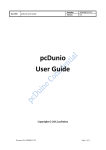
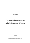
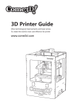
PiCoolFan User Manual Version 1.06 Print Date: 04.05.2014 PiCoolFan with Real Time Clock Advanced Pi Cooling Fan System for use with RaspberryPi® User Manual Version 1.06 “Raspberry Pi” is a trademark of the RaspberryPi Foundation Firmware Release 1 and 2 Hardware Release 1 it is Pi - it is Cool - it is Fun © Pi Modules - Intelligent Modules for your RaspberryPi® www.pimodules.com 1 PiCoolFan User Manual Version 1.06 Print Date: 04.05.2014 Credits Our Company would like to thank the following people that reviewed and, many times, commented and corrected this document before we released it to the public domain. Marcello Antonucci - Italy Mathew E. Rivers - USA © Pi Modules - Intelligent Modules for your RaspberryPi® www.pimodules.com 2 PiCoolFan User Manual Version 1.06 Print Date: 04.05.2014 Table of Contents Credits............................................................................................................................... 2 Introduction ...................................................................................................................... 4 Applications ...................................................................................................................... 4 System .............................................................................................................................. 4 Features ............................................................................................................................ 4 What is in the BOX? ........................................................................................................... 6 Hardware Installation ........................................................................................................ 7 Software Installation ....................................................................................................... 15 Setting-up the I2C interface and RTC ............................................................................ 15 The Peripheral I2C Control – PICo – Interface ................................................................... 19 PiCO Commands Summary .......................................................................................... 20 Examples of commands ............................................................................................... 22 LED based Simple User Interface ..................................................................................... 23 Technical Specifications ................................................................................................... 24 Firmware Updates ........................................................................................................... 27 © Pi Modules - Intelligent Modules for your RaspberryPi® www.pimodules.com 3 PiCoolFan User Manual Version 1.06 Print Date: 04.05.2014 PiCoolFan – Advanced Pi Cooling Fan System Introduction The PiCoolFan is an Advanced Cooling Fan System for the RaspberryPi®, one that offers total temperature control over the RaspberryPi®. It is addressed to all RaspberryPi® users whose board reaches a high temperature, for whatever reason. There is no need for any additional cabling or Power Supply, as the PiCoolFan is powered by the same Power Supply of your original RaspberryPi® board; just insert the PiCoolFan controller on top of the P1 connector of your RaspberryPi®. The PiCoolFan is equipped with an embedded temperature measurement system that continuously checks the RaspberryPi® PCB temperature with a dedicated sensor, and according to the measured temperature, the PiCoolFan micro controller starts, stops, or regulates the rotational speed of the embedded micro-fan. Thanks to the Air Distribution Plate, the PiCoolFan cools not only the microprocessor on the RaspberryPi® board but all the heat-generating devices, as well as the whole RaspberryPi® PCB. The embedded microcontroller is easily accessible by the user trough the I2C PICo interface and allows reading of the measured temperature, setting of temperature threshold, as well as starting/stopping the embedded micro fan. In addition the PiCoolFan offers on the same PCB a battery backed RTC and Real Time Powering Voltage Monitoring. Applications The PiCoolFan as an add-on module is addressed to all RaspberryPi® users that need to have a total control over the RaspberryPi® board temperature especially when running outdoor or in high temperature environments. The embedded micro-fan is of high quality, produces with very low noise (also thanks to the embedded PWM control technology), and is long lived. System The PiCoolFan module consists of the following units: The PWM Temperature Adjustment Fan Controller unit The micro-Fan Battery (not included) backed RTC The Air Distribution Plate (fit-in to most of the cases) Features The features of the PiCoolFan module are the following: Powering from the P1 connector of the RaspberryPi® Micro-controller supervised PWM FAN speed regulation © Pi Modules - Intelligent Modules for your RaspberryPi® www.pimodules.com 4 PiCoolFan User Manual Version 1.06 Print Date: 04.05.2014 Plug and Play 3 LED based information system (Red - hot, Blue - cold, Flashing Green – powering status) Full control over the system via I2C interface (The PICo Interface): o Unconditional Fan ON/OFF o PWM FAN speed regulation o Temperature threshold set/get o Current System Temperature read Supports Celsius and Fahrenheit scale Real Time powering voltage monitoring with programmable threshold o Flashes continuously Green if power is within thresholds o Flashes fast if power is higher than threshold o Flashes slow if power is lower than threshold Can be used inside of the most of already existing cases Embedded RTC with separated Battery (not included) © Pi Modules - Intelligent Modules for your RaspberryPi® www.pimodules.com 5 PiCoolFan User Manual Version 1.06 Print Date: 04.05.2014 What is in the BOX? This package comes with everything you need to start using the PiCoolFan right out of the box. It is assembled, tested and contains all required accessories. A little work is necessary in order to setup the complete RaspberryPi® and PiCoolFan in a single full operating system. Each Package contains the following parts: The PiCoolFan module (PCB) assembled and tested Air Distribution plate FAN with cable Set of 2 pcs of tree clips required for FAN mounting onto Air Distribution Plate Set of 5 pcs of Rubber spacers required for the Air distribution mounting © Pi Modules - Intelligent Modules for your RaspberryPi® www.pimodules.com 6 PiCoolFan User Manual Version 1.06 Print Date: 04.05.2014 Hardware Installation Before assembly, please print out of the page 9 with guidelines where to place the rubber spacers on the Air Distribution Plate. Follow the following steps in order to assemble and run the PiCoolFan. Place the Air Distribution Plane on the desktop Remove the protective tapes from the Air Distribution Plate © Pi Modules - Intelligent Modules for your RaspberryPi® www.pimodules.com 7 PiCoolFan User Manual Version 1.06 Print Date: 04.05.2014 After removing the protective tapes (both sides) from the Air Distribution Plate, you will have the above picture. Then print out the below page in order help of placement of the spacing rubbers. Scale of below picture is 1:1. Setting of the printer should be like in the below picture in order to achieve scale 1:1. © Pi Modules - Intelligent Modules for your RaspberryPi® www.pimodules.com 8 PiCoolFan User Manual Version 1.06 © Pi Modules - Intelligent Modules for your RaspberryPi® www.pimodules.com Print Date: 04.05.2014 9 PiCoolFan User Manual Version 1.06 Print Date: 04.05.2014 Lay the Air Distribution Plate on top of the Spacing Rubbers Placement Guide, and glue the self adhesive Spacing Rubbers to the Air Distribution Plate as shown. Remove the protective (brown) tape only from one side. The second self-adhesive side is used for permanent assembly of the Air Distribution Palate on the RPi. However it is not © Pi Modules - Intelligent Modules for your RaspberryPi® www.pimodules.com 10 PiCoolFan User Manual Version 1.06 Print Date: 04.05.2014 necessary. The second layer protective (brown) tape (if decided) should be removed just before final placement of the PiCoolFan on the RaspberryPi®, and not before. Prepare the tree clips and pass them over the 2 holes. Please take care to have them on the proper side. Prepare the FAN to be mounted over the Air Distribution Plate using the already assembled tree clips. © Pi Modules - Intelligent Modules for your RaspberryPi® www.pimodules.com 11 PiCoolFan User Manual Version 1.06 Print Date: 04.05.2014 Put the FAN on the tree clips and press it to the Air Distribution Plate in order to stabilize the whole construction. Be carefully to not touch the Fan blades when pressing the fan to the Air Distribution Plate. Therefore it is requested to press only over the outside are of the fan. Take care about cable placement side as also about fan Air flow polarity. After Assembly the above construction will be available. Fan will be close touching the Air Distribution Plate. © Pi Modules - Intelligent Modules for your RaspberryPi® www.pimodules.com 12 PiCoolFan User Manual Version 1.06 Print Date: 04.05.2014 Please insert the coin battery to the battery holder if planning to use the RTC. However, it is not necessary if you are not planning to use the RTC. Fit in the FAN connector to the PiCoolFan PCB socket. The PiCoolFan FAN, PCB and the Air Distribution Plate after the assembly will looks like above picture. © Pi Modules - Intelligent Modules for your RaspberryPi® www.pimodules.com 13 PiCoolFan User Manual Version 1.06 Print Date: 04.05.2014 Place the Air Distribution Plate on the RPi, if needed remove the brown tape from the rubber spacers in order to use self adhesive facility to glue it on the RPi. Insert the coin battery to the battery holder on the PiCoolFan controller board if planned to be used the RTC. Take care about battery polarity marked on the battery holder. Inserting the battery with inverse polarity will not destroy the system, it will cause only that RTC will not work. Fit in the PiCoolFan controller board on the P1 connector taking into account that the Temperature Sensor needs to be placed inside the hole of the Air Distribution Plate and need to closely touch the RaspberryPi® PCB near the C15. Please be sure that the FAN supply cable is placed in a proper side and free area. © Pi Modules - Intelligent Modules for your RaspberryPi® www.pimodules.com 14 PiCoolFan User Manual Version 1.06 Print Date: 04.05.2014 Now you can start Using PiCoolFan. The system is ready to be used and do not need any interface from the user. In order to use more advanced functionality please follow the next chapter of the manual. Software Installation This section describes how to program, read, set and handle all parameters of the PiCoolFan including the RTC. This also specifies the PICo interface. Setting-up the I2C interface and RTC The I2C Ports on the RaspberryPi® is not enabled by default. Follow these steps to enable the I2C port and then the RTC communicating through I2C with RaspberryPi®. First it is necessary to edit the config file that sets the I2C port to default disabled. This setting is stored in /etc/modprobe.d/raspi-blacklist.conf. Use nano to edit this but you can also use any other editor you are comfortable with. $sudo nano /etc/modprobe.d/raspi-blacklist.conf Once this file is open find this line blacklist i2c-bcm2708 and comment it out by adding# to the front of it. © Pi Modules - Intelligent Modules for your RaspberryPi® www.pimodules.com 15 PiCoolFan User Manual Version 1.06 Print Date: 04.05.2014 #blacklist spi-bcm2708 #blacklist i2c-bcm2708 Edit /etc/modules $sudo nano /etc/modules And add the following: i2c-bcm2708 i2c-dev rtc-ds1307 Add the modules to the kernel (they will automatically be added on subsequent boots from /etc/modules): $sudo modprobe i2c-bcm2708 $sudo modprobe i2c-dev $sudo modprobe rtc-ds1307 Reboot the system $sudo reboot Install I2C tools $sudo apt-get install i2c-tools Look for ID #68 with i2cdetect On a 256MB Raspberry Pi Model A: $sudo i2cdetect –y 0 On a 512MB Raspberry Pi Model B: $sudo i2cdetect –y 1 The result should look like: © Pi Modules - Intelligent Modules for your RaspberryPi® www.pimodules.com 16 PiCoolFan User Manual Version 1.06 Print Date: 04.05.2014 I2C PiCoolFan Simulated DS1307 RT Clock and PICo interface detection There are visible two I2C addresses. The first one (0x68) is the RTC address and the second one (0x6C) is the PICo interface address. Then as roots do the following for model of RaspberryPi® you have On a 256MB Raspberry Pi Model A: $sudo bash # echo ds1307 0x68 > /sys/class/i2c-adapter/i2c-0/new_device # exit On a 512MB Raspberry Pi Model B: $sudo bash # echo ds1307 0x68 > /sys/class/i2c-adapter/i2c-1/new_device # exit The result should look like: PiCoolFan Simulated DS1307 Clock sudo bash commands execution Then check for time from the clock (which will show Sat 01 Jan 2000 if it is the first time it is used): $sudo hwclock -r © Pi Modules - Intelligent Modules for your RaspberryPi® www.pimodules.com 17 PiCoolFan User Manual Version 1.06 Print Date: 04.05.2014 Then write the current system time to the clock: $sudo hwclock -w Then edit /etc/rc.local: $sudo nano /etc/rc.local and add the following before exit 0: On a 256MB Raspberry Pi Model B: echo ds1307 0x68 > /sys/class/i2c-adapter/i2c-0/new_device hwclock -s On a 512MB Raspberry Pi Model B: echo ds1307 0x68 > /sys/class/i2c-adapter/i2c-1/new_device hwclock -s © Pi Modules - Intelligent Modules for your RaspberryPi® www.pimodules.com 18 PiCoolFan User Manual Version 1.06 Print Date: 04.05.2014 The Peripheral I2C Control – PICo – Interface The PICo is an implementation of I2C interface adapted for easy control of the peripherals connected to the RaspberryPi® via command line. Values over the PICo interface could be presented as HEX or BCD coded numbers. These give the user the ability to handle supported devices just by human recognized commands. In the PICo interface, due to the mask feature, there are implemented multiple I2C addresses existing on a single I2C interface, that are spited to each peripherals. It allows co-existing multiple devices over a single I2C interface (i.e. FAN control system with RTC). Thanks to human-understandable and simple commands, control of peripherals is extremely simple. Control from programming language is also possible and as easy. The core concept of the PICo interface is that all peripheral device control and data exchange between it and RaspberryPi® variables are common for the I2C interface as also for the peripheral itself. Therefore, any change of them by either the RaspberryPi® or the peripheral causes immediate update and action. © Pi Modules - Intelligent Modules for your RaspberryPi® www.pimodules.com 19 PiCoolFan User Manual Version 1.06 Print Date: 04.05.2014 PiCO Commands Summary Address 0 or 0x00 Name mode Type byte R/W Write 1 or 0x01 speed byte Write 2 or 0x02 ctemp word Read 4 or 0x04 ttemp word Write 6 or 0x06 scale byte Write 7 or 0x07 fstat byte Read 8 or 0x08 vcc_pi word Read 10 or 0x0A vcc_upi word Write 12 or 0x0C vcc_dpi word Write 14 or 0x0E version byte R/W 15 or 0x0F rtccf byte R/W Explanation 0 – unconditional FAN OFF (with speed defined in variable 1) 1 – unconditional FAN ON (with speed defined in variable 1) 2 – FAN AUTO ON/OFF controlled by PCF Default value: 2 0 – FAN speed 00% (OFF) 1 – FAN speed 100% 2 – FAN speed 25% 3 – FAN speed 50% 4 – FAN speed 75% Default value: 3 Contains actual system temperature in BCD format – need to be read as word If Celsius selected then 2 digits If Fahrenheit selected then 2/3 digits Threshold temperature in BCD format Default value: 42 DEG Celsius Celsius or Fahrenheit 0 – Celsius 1 – Fahrenheit Default value: 0 Current FAN status: 1 – Running (at any speed) 0 – Not Running Actual value of VCC supplying RPi on P1 5V Pin in 10th of mV in BCD format Up Limit of VCC supplying RPI on P1 5V Pin in 10th of mV in BCD format – need to be read as word Default value: 520 (5.2 V DC) Down Limit of VCC supplying RPi on P1 5V Pin in 10th of mV in BCD format – need to be read as word Default value: 480 (4.8 V DC) Read: Firmware and Hardware Version 0xHF (Hardware, Firmware) Write: 0x00 then restore factory defaults Write: 0xEE then read PCF data from flash memory Write: 0xFF then store PCF data to flash memory Change the RTC timer for multiples of 1 tick per second Timers tick is 1/32768 Hz= 0,000030517578125 sec Write: 0x00 or 0x80 not change the RTC tick Write: 0x01 – 0x79 change the RTC tick by subtract tick multiplication from the standard timer values, therefore it will decrease the “duration” of each second by multiple value of timer ticks – counted second will be shorter, so RTC will be running faster Write: 0x81 – 0xFF change the RTC tick by adding tick multiplication to the standard timer values, therefore it will increase the “duration” of each second by multiple value of timer ticks – counted second will be longer, so RTC will be running slower Adding or subtract of one tick change the 24 hours RTC by 86400 * 0,000030517578125 sec = 2,63671875 seconds © Pi Modules - Intelligent Modules for your RaspberryPi® www.pimodules.com 20 PiCoolFan User Manual Version 1.06 Print Date: 04.05.2014 In order to handle the PICo command a write or read action should be performed to the I2C on the address where the PICo interface has been assigned. For the PiCoolFan the address is set to 0x6C and any communication should be done though this address. For reading of the word variable the w should be placed at the end of line. It is a good practice after changing of any value to proceed with FLASH memory update. It is important to notice that if RTC battery exists in the PiCoolFan, data remains in the RAM as long the battery is supplying the PiCoolFan. However, if user needs to have them stored permanently and have them available even if battery discharges, a FLASH store command should be proceeding. © Pi Modules - Intelligent Modules for your RaspberryPi® www.pimodules.com 21 PiCoolFan User Manual Version 1.06 Print Date: 04.05.2014 Examples of commands $sudo i2cget –y 1 0x6C 2 w Will generate the result of the current temperature in Celsius and in BCD format in order to simplify the command line human reading 0x0034 This means that system temperature is 34 degrees in Celsius scale $sudo i2cset –y 1 0x6C 6 1 This means that system temperature variables will be presented in Fahrenheit scale. The PiCoolFan will automatically recalculate values to the proper scale. A visual action will be visible when changing the scale. $sudo i2cset –y 1 0x6C 6 0 This means that system temperature variables will be presented in Celsius scale. . The PiCoolFan will automatically recalculate values to the proper scale. A visual action will be visible when changing the scale. $sudo i2cset –y 1 0x6C 0 1 Will switch unconditional ON the FAN with the speed defined in the variable ‘1’ $sudo i2cset –y 1 0x6C 0 0 Will switch unconditional OFF the FAN with the speed defined in the variable ‘1’ $sudo i2cget –y 1 0x6C 8 w Will read the actual voltage on the P1 5 V pin and give value of 0XXX in 10th of mV 0x0496 It means 4.96 V DC in BCD format © Pi Modules - Intelligent Modules for your RaspberryPi® www.pimodules.com 22 PiCoolFan User Manual Version 1.06 Print Date: 04.05.2014 LED based Simple User Interface There are 3 single color LEDs that helps the user to see what happens with the system without accessing any command. GREEN LED Lights continuously when P1 5V is within the requested range Flashes fast if P1 5V is above threshold - default 5.2 V Flashes slow if P1 5V is below threshold- default 4.8 V BLUE LED Lights when temperature of the system is below the threshold (factory default 42 Celsius). Fan is not running. RED LED Lights when temperature of the system is above the threshold (default is 42 Celsius). Fan is running. © Pi Modules - Intelligent Modules for your RaspberryPi® www.pimodules.com 23 PiCoolFan User Manual Version 1.06 Print Date: 04.05.2014 Technical Specifications RTC Recommended Coin Battery RTC current consumption from the coin battery when Power Down RTC accuracy PiCoolFan controller board power supply Power Down Mode threshold on 5V P1 connector (will run battery backed RTC only) PiCoolFan controller board current consumption (without FAN) FAN FET switch electrical specifications FAN current consumption 5 VDC on P1 connector measure system accuracy Acquisition Frequency (Temperature/Voltage) Default Threshold Temperature RTC interface I2C address PiCO interface I2C address CR1225 BR1225 LM1225 1225 CR1220 BR1220 LM1220 1220 20 uA 20 ppm 5 VDC from P1 connector 4.0 V DC PiCoolFan without LED: 2 mA@5V Each LED: 9 mA@5V 400mA, 5 VDC (from P1 connector) Mode 0 (OFF): 0 mA@5V Mode 1 (100%): 170 mA@5V Mode 2 (25%): 65 mA@5V Mode 3 (50%): 95 mA@5V Mode 4 (75%): 125 mA@5V Better than 1% 10 Hz 42 DEG Celsius 0x68 (0xD0) 0x6C (0xD8) © Pi Modules - Intelligent Modules for your RaspberryPi® www.pimodules.com 24 PiCoolFan User Manual Version 1.06 © Pi Modules - Intelligent Modules for your RaspberryPi® www.pimodules.com Print Date: 04.05.2014 25 PiCoolFan User Manual Version 1.06 © Pi Modules - Intelligent Modules for your RaspberryPi® www.pimodules.com Print Date: 04.05.2014 26 PiCoolFan User Manual Version 1.06 Print Date: 04.05.2014 Firmware Updates Our company is continuously developing and upgrading PiCoolFan firmware. However due to extremely low footprint and costs of the micro controller used in the PiCoolFan, it cannot hold a bootloader feature. Therefore any future firmware updates will be provided to customers as a complete PiCoolFan controller board replacement. This PiCoolFan controller board should be bought and paid by user as a new device (without all other components) including shipping costs from listed distributors. However the price of this part will be very low. As an alternative solution the newest firmware of the PiCoolFan in format of a HEX file will be provided on our website. Therefore peoples that have a programmer of the Microchip Technology Inc. PIC16® microcontroller will have the ability to proceed with firmware updates on their side, free of any charge. Such programmers are wide available to buy over the internet. Our company recommends the original Microchip Technology Inc. PICKit 3. All products developed and planning to be develop by our company are using or will use as a microcontroller exclusively one of the wide line of Microchip Technology Inc. PIC® microcontrollers (8 bits, 16 bits or 32 bits). © Pi Modules - Intelligent Modules for your RaspberryPi® www.pimodules.com 27 PiCoolFan User Manual Version 1.06 Print Date: 04.05.2014 WARRANTY PiCoolFan is warranted to be free from defects in materials and workmanship from the date of purchase for a 12 month period. Warranty excludes, normal wear and tear, accidental or deliberate damage. We will accept returns ONLY on the following conditions. These conditions do not affect your statutory rights. In the case of faulty items we will repair the items as per the manufacturer’s original warranty. Products which are returned for warranty repair will be forward shipped at the customer’s expense. After assessment, and if the products are covered under warranty, we will pay return freight costs. However, if a fault cannot be found, and the product is deemed to be in good working order or not covered by warranty, the customer pays shipping both ways and pays Pi Modules, a service fee prior to the return of the products according to Pi Modules service price list. If the goods are covered under warranty, we will cover only the return costs, and the repair or replacement of the product as we see fit. We will only accept for repair only the items, which are returned in the original packaging (including all parts contained in the packaging) and are undamaged (including original packaging). Warranty excludes, normal wear and tear, accidental or deliberate damage, any such items will not be replaced. In the case of refund, no such refund will ever exceed the original purchase cost of the item and will not include any associated postage costs. © Pi Modules - Intelligent Modules for your RaspberryPi® www.pimodules.com 28