1
Wireless Short Range Network for the Active
Mirror Control of the CTA Experiment
Bachelor Thesis
Mathematisch-naturwissenschaftliche Fakultät
der
Universität Zürich
Roman Gredig
Prof. Dr. Ulrich Straumann
Dr. Achim Vollhardt
Zürich
Juli 2009
Acknowledgments
I thank Prof. Ulrich Straumann for giving me the opportunity to make this bachelor
thesis in his group.
A special thank goes to my tutor Dr. Achim Vollhardt who supported me always, took
the time to answer all my questions and let me work in his laboratory.
Further I’d like to thank Boris Begemann who gave me some important tips in developing my C# applications.
3
Contents
Contents
1 Introduction
1.1 The Cherenkov Telescope Array (CTA) Project . . . . . . . . . . . . . .
1.2 The Goal of this Bachelor Thesis . . . . . . . . . . . . . . . . . . . . . . .
2 Realizing Wireless Communication
2.1 Design Parameters . . . . . . . . . . .
2.2 Why Using Wireless Communication?
2.3 Comparison of Different Technologies .
2.3.1 Bluetooth . . . . . . . . . . . .
2.3.2 Wireless USB . . . . . . . . . .
2.3.3 Wi-Fi . . . . . . . . . . . . . .
2.3.4 IEEE 802.15.4 . . . . . . . . .
.
.
.
.
.
.
.
.
.
.
.
.
.
.
.
.
.
.
.
.
.
.
.
.
.
.
.
.
.
.
.
.
.
.
.
.
.
.
.
.
.
.
.
.
.
.
.
.
.
3 The RF Data Modules
3.1 XBee 802.15.4 OEM RF Modules . . . . . . . . . .
3.1.1 Set-up a Network with Xbee . . . . . . . .
3.1.2 Short User Manual . . . . . . . . . . . . . .
3.1.3 The API Frame Specifications . . . . . . . .
3.2 The Z-Accel 2.4 GHz ZigBee Processor CC2480 . .
3.2.1 Set-up a Network with the CC2480 . . . . .
3.2.2 Application Profiles and Binding in ZigBee
3.2.3 Controlling the Modules . . . . . . . . . . .
3.2.4 Short User Manual . . . . . . . . . . . . . .
.
.
.
.
.
.
.
.
.
.
.
.
.
.
.
.
.
.
.
.
.
.
.
.
.
.
.
.
.
.
.
.
.
.
.
.
.
.
.
.
.
.
.
.
.
.
.
.
.
.
.
.
.
.
.
.
.
.
.
.
.
.
.
.
.
.
.
.
.
.
.
.
.
.
.
.
.
.
.
.
.
.
.
.
.
.
.
.
.
.
.
.
.
.
.
.
.
.
.
.
.
.
.
.
.
.
.
.
.
.
.
.
.
.
.
.
.
.
.
.
.
.
.
.
.
.
.
.
.
.
.
.
.
.
.
.
.
.
.
.
.
.
.
.
.
.
.
.
.
.
.
.
.
.
.
.
.
.
.
.
.
.
.
.
.
.
.
.
.
.
.
.
.
.
.
.
.
.
.
.
.
.
.
.
.
.
.
.
.
.
.
.
6
6
6
.
.
.
.
.
.
.
8
8
9
10
10
10
11
11
.
.
.
.
.
.
.
.
.
14
14
14
15
19
20
21
21
22
23
.
.
.
.
.
.
.
.
.
26
26
26
26
26
26
27
28
28
29
4 The
4.1
4.2
4.3
4.4
Printed Circuit Board
Definition . . . . . . . . . . .
The Development of the PCB
Requirements of the PCB . .
The Components on the PCB
4.4.1 The Power Supply . .
4.4.2 The Jumpers . . . . .
4.4.3 Interface . . . . . . . .
4.4.4 The Xbee-Module . .
4.4.5 The CC2480-Module .
5 The
5.1
5.2
5.3
Module-Control-Application
30
Programming Language . . . . . . . . . . . . . . . . . . . . . . . . . . . . 30
Purpose of the Application . . . . . . . . . . . . . . . . . . . . . . . . . . 30
Controlling the Xbee Module . . . . . . . . . . . . . . . . . . . . . . . . . 31
4
.
.
.
.
.
.
.
.
.
.
.
.
.
.
.
.
.
.
.
.
.
.
.
.
.
.
.
.
.
.
.
.
.
.
.
.
.
.
.
.
.
.
.
.
.
.
.
.
.
.
.
.
.
.
.
.
.
.
.
.
.
.
.
.
.
.
.
.
.
.
.
.
.
.
.
.
.
.
.
.
.
.
.
.
.
.
.
.
.
.
.
.
.
.
.
.
.
.
.
.
.
.
.
.
.
.
.
.
.
.
.
.
.
.
.
.
.
.
.
.
.
.
.
.
.
.
.
.
.
.
.
.
.
.
.
.
.
.
.
.
.
.
.
.
.
.
.
.
.
.
.
.
.
.
.
.
.
.
.
.
.
.
.
.
.
.
.
.
.
.
.
.
.
.
.
.
.
.
.
.
.
.
.
.
.
.
.
.
.
.
.
.
.
.
.
.
.
.
.
.
.
.
.
.
.
.
.
.
.
.
.
.
.
.
.
.
Contents
5.4
5.3.1 Example of the Usage of the Application . . . . . . . . . . . . . . . 32
Controlling the CC2480 Module . . . . . . . . . . . . . . . . . . . . . . . . 34
5.4.1 Example of the Usage of the Application . . . . . . . . . . . . . . . 35
6 Tests and Evaluation
6.1 Test Scenarios with the Xbee Modules . .
6.1.1 Broadcasting . . . . . . . . . . . .
6.1.2 Individual Addressing . . . . . . .
6.2 Test Scenarios with the CC2480 Modules
6.2.1 Broadcasting . . . . . . . . . . . .
6.2.2 Individual Addressing . . . . . . .
6.3 Summarized Results . . . . . . . . . . . .
6.4 Conclusion and Open Questions . . . . . .
.
.
.
.
.
.
.
.
.
.
.
.
.
.
.
.
.
.
.
.
.
.
.
.
.
.
.
.
.
.
.
.
.
.
.
.
.
.
.
.
.
.
.
.
.
.
.
.
.
.
.
.
.
.
.
.
.
.
.
.
.
.
.
.
.
.
.
.
.
.
.
.
.
.
.
.
.
.
.
.
.
.
.
.
.
.
.
.
.
.
.
.
.
.
.
.
.
.
.
.
.
.
.
.
.
.
.
.
.
.
.
.
.
.
.
.
.
.
.
.
.
.
.
.
.
.
.
.
.
.
.
.
.
.
.
.
.
.
.
.
.
.
.
.
37
38
38
38
41
41
41
42
43
References
45
A Details of the PCB design
46
B Listings
48
B.1 Xbee Application . . . . . . . . . . . . . . . . . . . . . . . . . . . . . . . . 48
B.2 CC2480 Application . . . . . . . . . . . . . . . . . . . . . . . . . . . . . . 58
5
1 Introduction
1 Introduction
1.1 The Cherenkov Telescope Array (CTA) Project
CTA is a project to build a ground-based gamma-ray telescope array to observe cosmic
gamma-rays from about 10 GeV to more than 100 TeV. It is intended to analyze gammaray sources coming from our or other galaxies. It is planned to have 5–10 times higher
sensitivity than current telescopes. [1] [2]
The observed cherenkov light is produced by high energy gamma quants. If they reach
atmospheric molecules they can undergo pair production by producing an electron and
positron. Those leptons can produce again photons by bremsstrahlung and compton
scattering. This photons begin again to produce electrons and positrons by pair production. Leptons produced this way have so high velocities1 that they generate cherenkov
light. This can be detected with the telescopes (see fig. 1).
1.2 The Goal of this Bachelor Thesis
This bachelor thesis is a concept study for the realization of a wireless short range data
network for the active mirror control of the CTA experiment. In the first part it has
been evaluated what kind of network is most qualified to fit the requirements.
In the second part two different modules, working with the IEEE 802.15.4 standard,
have been set up to perform first tests. This included a development of a printed circuit
board to operate the modules and an application written in C# to control them.
1
6
higher than the speed of light in the corresponding medium
1.2 The Goal of this Bachelor Thesis
Figure 1: Scematic of a cherenkov light cascade [3]
7
2 Realizing Wireless Communication
2 Realizing Wireless Communication
There are many different possibilities to realize a wireless network. For each field of
application there is another solution. It has to be chosen a system that fulfills the
qualifications.
2.1 Design Parameters
Figure 2: Schematic top view of a telescope dish with the mirrorsegments
To decide what kind of wireless network would be the best, the design parameters have
to be set. The CTA consists of many telescopes with different sizes. The biggest ones
will have a diameter of about 20 meters. Each mirror of a telescope will be segmented
to small hexagonal elements (up to ∼1000) (see fig. 2). Each segment will be mounted
on three points. On two points there will be a motor that allows to change the mirrorsegments’ orientation. Every element has to be adjusted in the right way to form together
the desired shape of the telescope. Additionally they have to compensate deformations
when the whole telescope changes its elevation angle. The telescope will change its
orientation about every 5 minutes.
8
2.2 Why Using Wireless Communication?
This means that for each telescope there has to be formed a network that allows the
controlling of all mirror-segemts from a central point. The network has to be able to
send and receive commands from every motor. Sending the command to adjust the
mirrors should be fast because of the 5 minute reset period. But the bandwidth of
the communication between the coordinator and the motor has not to be high, since a
positioning command just contains several bytes.
It should be easy to integrate the system into the other electronics and to control it
with common microprocessors. Because there is a huge amount of devices to be equipped
(hundreds of telescopes with up to 1000 motors), it should be cheap to equip the motors
with wireless data communication to hold down the costs. Also the energy consumption
has to be kept in sight.
Finally it would be the best, when the system uses a common open standard for not
being bounded to a specific manufacturer. Summarized, the system that will be used
has to respect the following parameters:
• low energy consumption
• cheap
• handle distances about 10–20 meters
• able to control up to 2000 nodes
• fast (not in bandwidth but by sending commands up to 2000 nodes)
• small (it has to fit into the AMC case)
• easy to integrate into the other electronics
• bidirectional communication
• protection of unwanted network access
• open standard
2.2 Why Using Wireless Communication?
Before different wireless technologies are compared, it has to be discussed why a wireless
solution should be considered. As explained above there are thousands of mirrors that
have to be controlled individually. Wireless communication is not the only way to do
this. In existing projects they are usually controlled by a wired data connection. One of
the biggest advantages of a wireless solution is the price. By using wireless techniques
it isn’t necessary that the motors have to be connected to a network via cables. This
means that it isn’t necessary to lay a data cable for every motor. Because of this huge
amount of mirrors one can save money by economize manpower and by using much less
9
2 Realizing Wireless Communication
cables. The only cables that are needed are the ones for the power supply which are also
much less delicate.
Another point is the connection to the motors. The AMC case is outdoors and therefore it has to be waterproof to protect the inner electronics. Every connection involves
the risk of a leak in the AMC case. Having cables also means that there is the risk to
have broken ones. Replacing a broken cable needs much more time than only replacing
a broken network module because a cable had potentially to be rerouted over the whole
telescope.
2.3 Comparison of Different Technologies
2.3.1 Bluetooth
Bluetooth [4] is a wireless protocol designed for data exchange over short distances based
on the IEEE 802.15.1 standard. It’s most known for data transfer between mobile phones
and/or head-sets. Bluetooth is working the ISM2 license free 2.4 GHz band. During communication the frequency hops between 79 different frequencies to minimize interference
with other devices. In a Bluetooth network exists one master and up to 7 active slaves
(piconet). Additionally there can be up to 255 devices in such a piconet. These devices
stay synchronized with the others but not active. Theoretically it’s possible to combine
such piconets to bigger networks by having devices that are registered in more than one
piconets. Such extended networks are called scatternet. In a scatternet exist devices
that are part of two piconets. They can transfer data from one piconet to another. But
this is very complicated: the different piconets are not synchronized and the mentioned
slave has to negotiate with more then one master when it is active in which piconet [5].
This leads to high latencies when a packet has to travel through the network by crossing
different piconets. In the Bluetooth stack exist no routing protocols so it had to be
realized in the application layer. The realizing of bigger network by using scatternets is
rather a theoretical approach.
Scatternets are not an effective way to realize bigger networks. Therefore, Bluetooth
is not an option for the CTA.
2.3.2 Wireless USB
Wireless USB is an extension of the existing Universal Serial Bus. It is designed to
connect peripheral devices to the computer. Wireless USB works on frequencies between
3.1 and 10.6 GHz. It uses a star topology. The network consists of one host and (up to)
127 devices connected to it. Those devices can only communicate with the host. Data
rates are up to 480 Mbit/s (distances lower than 3 meters).
Wireless USB is not an option because the network size is limited to 127 devices.
2
Industrial, Scientific, and Medical Band
10
2.3 Comparison of Different Technologies
2.3.3 Wi-Fi
Wi-Fi, also known as Wireless LAN (WLAN), is based on the IEEE 802.11a/b/g/n
standard. It’s most known to connect computers to the internet with broadband speed.
Wi-Fi allows network sizes up to 2007 devices. This would be close enough to control
the biggest telescopes. Wi-Fi is designed for having high data rates (∼54 Mbit/s) and
ranges about 100 meters. Wi-Fi doesn’t meet the design parameters because it has too
high power consumption (10 times higher than IEEE 802.15.4 for example). Because of
the high range of Wi-Fi there is also the problem that different telescopes would interfere
between each other. Only three different Wi-Fi networks can operate in an overlapping
region without interfering.
2.3.4 IEEE 802.15.4
Figure 3: the layers of the OSI model [6]
IEEE 802.15.4 is a standard that specifies the physial (PHY) and the media access
control (MAC) layer for personal area networks (see fig. 3). It focuses on low-cost,
low-speed and low-energy consumption. Some of the main characteristics are:
• data rate up to 250 kb/s (@ 2.45 GHz)
11
2 Realizing Wireless Communication
• star or peer-to-peer operation
• 16 or 64 bit addressing of the devices
• acknowledged protocol for transfer reliability
• low power consumption
• 16 channels in the 2.45 GHz band, 30 channels in the 915 MHz band, 3 channels
in the 868 MHz band
This standard defines two different types of devices that can join the network. A fullfunction device (FFD) has to support all features of the standard. This means that
it can operate as a personal area network coordinator, a coordinator or an end-device.
FFD can start and manage networks. Each network needs one Personal Area Network
(PAN) coordinator. FFDs can talk to other FFDs or RFDs. Reduced-function devices
(RFD) can only join to a existing network. They are only able to talk to FFDs. In
order to run a network, at least one FFD is required. RFDs are designed for simple
applications (like a light switch).
Figure 4: The different IEEE 802.15.4 topologies. Left picture: star topology. The PAN coordinator is in red, the end-devices are white. Right picture: peer-to-peer topology.
The PAN Coordinator is in red, the other joined devices are FFDs (in blue).
Network Topologies IEEE 802.15.4 supports two different network topologies. It can
operate in a star topology or a peer-to-peer topology. In star topology (see fig. 4) the
communication is always between a central point (the PAN coordinator) and the end
devices. They can only communicate with the controller.
12
2.3 Comparison of Different Technologies
In a peer-to-peer topology there is also a PAN. But here, every device can communicate
to others that are in its range.
ZigBee ZigBee specifies a protocol stack that is based on IEEE 802.15.4. ZigBee
specifies three different devices. There are end-devices with a simplified stack (i.e. RFD
in IEEE 802.15.4). Additionaly there is a coordinator that manages the network and a
router. Routers are FFDs that allow to route data. This is necessary for a network with
tree topologies. With routers it’s possible to extend networks. Star, mesh and cluster
tree networks can be implemented.
Conclusion Networks build with IEEE 802.15.4, with or without ZigBee, seems to be
the best choice. They fulfill all requirements defined in paragraph 2.1. They are cheap
and the only ones that support such a big number of devices in a network. As it is an
open standard there is no danger to be dependent to a specific manufacturer. Because the
area that has to be covered is relatively small, there is no routing or network extension
needed. All motors of the telescope are near enough to contact a central point directly.
This means that a simple star topology can already realized with IEEE 802.15.4 without
the ZigBee stack. This helps to keep the implementation of a network as simple as
possible.
13
3 The RF Data Modules
3 The RF Data Modules
For this thesis two different modules coming from different manufacturers have been
tested. Both are modules working on the IEEE 802.15.4 standard. They use the same
technique to build a network and to communicate among each other.
3.1 XBee 802.15.4 OEM RF Modules
The first module that is tested is the XBee 802.15.4 OEM RF Module. This module is
produced by Digi (formerly known as MaxStream). It is engineered to meet the IEEE
802.15.4 standard.
This modules are also available with other firmwares. There is a firmware with a
ZigBee stack (see chapter 3.2) and one with DigiMesh. DigiMesh is a proprietary peerto-peer topology without specific routers or coordinators. In a DigiMesh network all
devices can route data. They form dynamically a network in which all devices are
reachable. If one device breaks down, the routing will be changed for having still all
other devices connected to the network.
In our application the area of one network is small. Therefore there is no data routing
between two modules needed.
To find out which firmware is the best, the company reselec ag 3 has been contacted.
reselec ag is a swiss company that sells Xbee Modules and supports customers in developing networks. For our application the XBee 802.15.4 firmware is the best. It’s
simple and can support such a big network. There are two different modes to operate
the modules:
Peer-to-Peer: This is the default mode. In this mode the modules work in a peer-to-peer
topology. There are no Master/Slave relationships.
NonBeacon (with Coordinator): In this mode, one module has to be configured as a
coordinator. The coordinator manages the network. All other devices are so called
end-devices. They have to associate with the network via the coordinator.
3.1.1 Set-up a Network with Xbee
A network consists of one coordinator and one or more end-devices. Such a network
forms a PAN (Personal Area Network). Each PAN is identified via a unique number
(the PAN ID). Every device belonging to a specific PAN has to have set this PAN ID.
This prevents miscommunication between different networks. This is very important
when there are different networks that are close together (e.g. two different telescopes).
3
http://www.reselec.ch
14
3.1 XBee 802.15.4 OEM RF Modules
Starting up the Coordinator The starting of a coordinator is controlled by the A2
command (for all commands refer to [7]). There can be made different modifications.
It is possible to perform active scans to detect existing PANs. The second setting is
to perform an energy scan during start up. Energy scan means that the coordinator
scans for energy on every channel for a given time. This procedure helps to find a free
channel where no other networks disturb the communication. It’s also possible to start
the coordinator neither performing an active scan nor an energy scan. Then it retains
the settings that are already programmed.
Starting up the End-Devices There exist also different startup configurations for the
end-devices. The end-devices can be configured to search for every coordinator that is
reachable. It can also be configured to associate only to a coordinator with a specific
PAN ID and/or specific channel.
In our application the network environment is well known and defined. Therefore it
would be the best to preset PAN ID and channel for every telescope. This renders a lot
of the dynamic configuring and association features unnecessary.
3.1.2 Short User Manual
General For setting up a network with the XBee Modules like described in 3.1.1, several
commands have to be sent. By factory setting they are in the so called transparent mode.
This means that all data coming in via the UART4 interface will be sent. Received data
will be output directly to the UART. For configuring the module, it has to be set in
the AT command mode. This can be done by sending the following sequence (consider
flowchart in figure 5):
-> wait 1 sec
+++
-> wait 1 sec
-> the device returns "OK"
Now it’s possible to configure the device via the AT commands. The AT command mode
can be left by sending
ATCN <CR>
After leaving the AT command mode, the device returns to the transparent mode. The
waiting time before and after sending the +++ can be adjusted with the ATGT command.
A complete sequence would be the following:
4
UART: Universal Asynchronous Receiver Transmitter. This is a interface that allows serial communication between the module and other devices. Data can be sent or received by a bit-serial data
stream.
15
3 The RF Data Modules
Transparent
Mode
send
command
don't send data
for 1 sec
send
<CR>
send
+++
don't send data
for 1 sec
device
returns
OK
send another
command?
yes
no
send
ATCN
<CR>
Transparent
Mode
Figure 5: flowchart for configuring the XBee Module by using AT commands while working in
transparent mode
-> wait 1 sec
+++
-> wait 1 sec
-> response: OK
ATCE1 <CR>
-> response: OK
ATMY20 <CR>
-> response: OK
ATCN <CR>
-> response: OK
<CR>
<CR>
<CR>
<CR>
Multiple commands can also be combined in one line, separated by commas, like in the
following example:
-> wait 1 sec
+++
-> wait 1 sec
16
3.1 XBee 802.15.4 OEM RF Modules
-> response: OK <CR>
ATDL1A0,WR,CN <CR>
-> response: OK, OK, OK <CR>
For this user manual we consider the following scenario: We have 3 devices forming a
network. Device A is the coordinator that starts a network. The coordinator will have
a 16-bit short address: 0x0000. Devices B and C work as end-devices which want to
associate with the network initialized by the coordinator. They will have the 16-bit
addresses 0x0001 and 0x0002.
Configuring the Coordinator To configure a module to operate as a coordinator, the
CE (Coordinator Enabled) parameter has to be set to 1. The coordinator can undergo
different start up sequences.
The A2 parameter controls how the coordinator starts. If the bit 0 of the A2 bitfield is
set, the coordinator sends on every channel a BeaconRequest command to the broadcast
address (0xFFFF) and broadcast PAN ID (0xFFFF). It listens then for beacons from any
coordinator. This procedure will be repeated for every channel. Finally, the coordinator
will either retain its PAN ID when no other coordinator has been found with this or it
will update its PAN ID to a new, unused ID. If the A2 bit 0 is set to 0, no active scan
is performed. The coordinator will retain its setting.
The bit 1 of the A2 bitfield controls whether the coordinator issues an energy scan
or not. If it is set to 1, the coordinator scans for energy on all channels. This helps
to find out on which channel exists a minimum of energy produced by other networks.
After scanning, the coordinator sets the channel setting to the channel with the least
energy. If the bit 1 is set to 0, the coordinator will not perform an energy scan and retain
its channel setting. The bit 2 of the A2 bitfield controls whether other end-devices are
allowed to join the network or not.
If addressing with the 16-bit short addresses is desired, every module needs a unique
address. This address can be set with the ATMY command. Here the coordinator will
have the 16-bit short address 0x0000.
This example shows how to configure the module to work as a coordinator that will
perform an energy scan during startup:
-> wait 1 sec
+++
-> wait 1 sec
ATCE1 <CR>
ATA26 <CR>
ATMY0 <CR>
ATWR <CR>
17
3 The RF Data Modules
The last command ATWR saves the settings to the non volatile memory. After a reset of
the coordinator, it will retain this settings. After every restart, the module will perform
a energy scan and search for a free channel.
Configuring the End-Devices For this example the end-devices will be configured to
search for a coordinator with any PAN ID on any channel. This can be controlled with
the A1 (End-Device Association Command). The A1 requires also a bitfield. Bit 2
controls whether the device tries to associate with a coordinator or not. If the bit 1
is set to 1, the device can associate with a PAN with any channel value. The bit 0
controls, whether the device can associate with a PAN with any PAN ID value or only
with a PAN with the same PAN ID like the end-device currently has. Furthermore we
only want that the end-devices communicate with the coordinator. Hence, it follows
that the destination where data has to be sent can be programmed once. By using
short addresses, two parameters have to be set. The destination high address has always
to be 0x0000. (ATDH0). The destination low address has to fit the MY address of the
destination device. For the end-devices it’s always the coordinator, that uses the MY
address 0x0000. For our example the setting is:
-> wait 1 sec
+++
-> wait 1 sec
ATA1F <CR>
ATMYx <CR> (with x > 0)
ATDH0 <CR>
ATDL0 <CR>
ATWR <CR>
Usage of the Network When the initial settings are made like above, the network
starts up automatically as desired. After the association procedure, all devices are ready
to receive and send data from/to the coordinator. As mentioned above, the modules
work by default configuration in the transparent mode. For the end-devices, this would
be the preferred modus. After an initial configuration there are no additional commands
to be sent. It’s not necessary to change the destination address for transmitting data due
to the fact that in our application they only have to talk to the coordinator. Principally
an initial configuration could be made before the module will be integrated to the AMC
unit. The microprocessor on the AMC has not to send any configuration commands to
the module itself. It has only to interpret commands coming from the coordinator and
send answers to it.
For the coordinator itself, the situation is more complex. It has to send commands to
different nodes (i.e. every motor). That’s the reason why it’s necessary to change the
destination low address before (the ATDL command). If an operation in transparent mode
18
3.1 XBee 802.15.4 OEM RF Modules
is desired, it has always to be changed into the AT command mode for changing the
destination address. This costs a lot of time. Another disadvantage of the transparent
mode is, that in point to multipoint systems, it is not clear from which remote module
incoming data comes, except it is implemented in the application that the remote address
is sent too.
Since there is also the possibility to use a module in the API mode5 , this would be
the preferred mode for the coordinator. In the API mode there is directly a command
to send data with the destination address as a part of the command. By using this API
command mode, it has not to be switched first to the AT command mode, changed the
destination address and then switched back to the transparent mode, before data can be
sent. Another advantage of the API command mode is, that every data send command
immediately returns a answer that indicates whether the transmission was successfully
or not.
The next subsection will explain the principles of the mentioned API command mode.
3.1.3 The API Frame Specifications
Start Delimiter
(1 Byte)
0x7E
Length
(Bytes 2-3)
MSB LSB
Frame Data
(Bytes 4-n)
API-specific Structure
Chksum
(Byte n+1)
1 Byte
Table 1: UART data frame in API operation
The API operation requires that the communication with the module is done in a structured interface. In the API Frame Specifications [7] it is defined how the commands
[responses] are sent [received] from the module. For using the API mode, the module
has to be configured appropriate. While being in the AT command mode it can be done
with the ATAP command:
ATAP0 sets the module to transparent operation
ATAP1 activates API Operation
ATAP2 activates API Operation with escaped characters
In the API operation a UART data frame is defined as seen in table 1. The first byte
that has to be transmitted is 0x7E. This indicates the start of a data frame. The next
two bytes indicate the number of bytes that includes the Frame Data. Now the Frame
Data follows. This is the actual API command with additional data in it. The last byte
that finishes a data frame is the checksum. The checksum ensures data integrity. The
calculation of the checksum is: 0xFF − (sum over all Frame Data bytes).
5
API: Application Programming Interface
19
3 The RF Data Modules
3.2 The Z-Accel 2.4 GHz ZigBee Processor CC2480
The second tested module is the CC2480 Z-Accel 2.4 GHz ZigBee Processor. This
module supports the ZigBee 2006 stack. Unlike the XBee 802.15.4 OEM RF Modules it
can build a real ZigBee network with coordinators, routers and end-devices. The CC2480
is produced by Texas Instruments. It comes in a small 7 x 7 mm QFN-486 package that
is a surface-mount device.
Figure 6: Example of a ZigBee network. The coordinator is in red, routers in blue and enddevices are white.
A ZigBee network consists of one coordinator and one or more end-devices and routers
(see fig. 6). The coordinator is the device that starts and manages the network. Since
ZigBee is based on IEEE 802.15.4, the coordinator has to specify some network parameters like the PAN ID and the channel.
When the coordinator started up, other devices can join this network. They can be
end-devices and routers. If there are routers in a network, other end-devices and routers
can join the network via these routers. In this case they are called childs of the router.
The possibility to have routers (that are childs of the coordinator or of other routers)
enables the network to have devices communicating between each other that are out
of their RF range. Messages between such two devices are then routed via the routers
in between. Depending on the ZigBee specifications and the limitations of the CC2480
module the network can have the following structure [8]:
6
QFN: Quad Flat No leads
20
3.2 The Z-Accel 2.4 GHz ZigBee Processor CC2480
• The maximum network depth (i.e. the hops between a device and the coordinator)
is limited to 6.
• Each router or coordinator can have up to 20 child devices. Of these, up to 6 can
be routers and the others end-devices.
3.2.1 Set-up a Network with the CC2480
The CC2480 control commands include the so called Simple API Interface (SAPI). The
SAPI allows a developer to build up a ZigBee network with the knowledge of only 10
commands. This is an easy way to begin developing ZigBee networks. All tests made
for this thesis with the CC2480 are made with the SAPI.
Starting up the Coordinator The device type of the module can be controlled with the
ZCD NV LOGICAL TYPE parameter. The value 0x00 stands for the coordinator. The PAN
ID for the network can be controlled by the ZCD NV PANID parameter. For the channel
on which the network has to work exists the ZCD NV CHANLIST parameter. This is a bit
mask of channels. If more than one channel is selected, the device will perform an energy
scan. Those channels with the highest energy will be discarded. After the energy scan
the device determines the number of existing (other) networks. Finally it will choose
the channel with the fewest networks on it.
After having set the network parameters, the application has to be registered. This is
done with the ZB APP REGISTER REQUEST. The coordinator is now ready to work. The
ZigBee stack can be started witch the ZB START REQUEST. Joining the network by other
devices is controlled with the ZB PERMINT JOINING REQUEST. This command allows to
control the joining for individual devices or a group of specific devices (i.e. routers,
end-devices).
Set-up end-devices The modules that have to work as an end-device can be set in the
corresponding modus with the ZCD NV LOGICAL TYPE. Again the application has to be
registered with the ZB APP REGISTER REQUEST command. The end-devices can now be
started with the ZB START REQUEST. After this, they try to connect to a network (via a
coordinator or a router that allows joining).
3.2.2 Application Profiles and Binding in ZigBee
As the CC2480 is a device using ZigBee, there is feature called Application Profile [8].
An application profile defines different devices (like a light on/off switch or the lamp),
a set of commands exchanged by the different devices and a format how the data is
exchanged between the devices.
Suchlike profiles can be either public or private. The sense of public profiles is interoperability. If one buys a lamp from manufacturer A with ZigBee modules from brand
21
3 The RF Data Modules
B it’s possible to buy a on/off switch from manufacturer B with a ZigBee module in it
from brand D. Because public profiles are well defined by the ZigBee Alliance those two
products are able to work together. If such a feature is not required, it’s possible to use
private profiles. Application profiles play an important role, when the binding feature is
used.
With binding it’s possible to generate logical links between devices at the application
layer. This means that an application can send data to another device without knowing
its destination address. The sending module can then look up the corresponding destination address from its binding table. During the registration of the application it will
be specified which module generates data or receives data.
For the test made in this thesis, the destination addresses were known (they can be
retrieved with the test application). Therefore the binding feature has not been used.
For setting up a network an application profile has to be registered. For this tests and
examples a simple light switch profile has been chosen. Because data transmission has
been performed with direct 16-bit addressing, it didn’t matter what kind of profile has
been chosen because the binding feature wasn’t used.
3.2.3 Controlling the Modules
The CC2480 can only be controlled by using a well defined application command interface
(similar to the API mode of the XBee modules). Because the CC2480 can’t be controlled
by using AT commands, it is suggested using an application (or a microprocessor) that
sends the commands in the right way.
General UART Communication and the Application Interface Communication between an application and the module has to happen in a well defined UART transport
frame format [9]. Every data frame has to begin with the start of frame indicator SOF
byte. The value is (in HEX) 0xFE. Next, the general format frame follows. This is
actually the specific command or message that has to be sent. The data frame has to
be closed with a checksum to ensure correct transmission between the module and the
application. The checksum is computed as an XOR of all the bytes from the general
format frame. Table 2 shows an overview of the data format. The general frame format
Start indicator
(1 Byte)
0xFE
General Frame Format
(Bytes 3 – 256)
Checksum
(1 Byte)
XOR of all Bytes in
the General Frame Format
Table 2: data frame format for the CC2480 API [9]
is well defined too. It contains three parts (see table 3). The first byte defines the length
22
3.2 The Z-Accel 2.4 GHz ZigBee Processor CC2480
of the data field. The next two bytes represent the command and the last part includes
the data. The content and size of the data field depends on the command and can be
empty (depending on the command).
Length
(1 Byte)
Command
(2 Bytes)
Data
(0-253 Bytes)
Table 3: general frame format for the CC2480 API [9]
3.2.4 Short User Manual
Considering a scenario with one coordinator and two end-devices the modules have to
be programmed appropriate.
The Coordinator The coordinator manages the whole network and has to be set up as a
first step. The flowchart in figure 7 shows the commands that have to be sent to configure
and start a module as a coordinator. The first commands reset the device completely.
This helps to bring it to a known state. After resetting, the device will be configured
working as a coordinator. As a next step, the application has to be registered. Finally
the ZigBee stack can be started. Now the coordinator is up and running. With the
last command the coordinator allows other devices to join the network. This command
includes a timeout byte. This byte specifies how long other devices can join the network.
The End-Devices To configure the other modules working as end-devices, the commands in the flowchart of fig. 8 have to be sent. The first steps are again to reset the
module and bring it in a known state. The next command sets the module to work as an
end-device. After that, the application can be registered and the ZigBee stack started.
The device will then try to connect to a coordinator or router to join a network. A
successfully joining will be confirmed with a status response after starting the stack.
Usage of the Network Having formed a network, all modules are ready to send or
receive data. All devices will get a 16-bit short address after having joined a network
successfully.
Sending data can be achieved by using the ZB SEND DATA REQUEST. With this command it’s possible to send data by using the 16-bit short address of the destination. The
short addresses 0xFFFC, 0xFFFD, 0xFFFE and 0xFFFF are reserved for using broadcasting
or the binding feature.
23
3 The RF Data Modules
Power up device
send
SYS_RESET_REQ
send
ZB_WRITE_CONFIGURATION
-> ZCD_NV_STARTUP_OPTION
-> CLEAR_CONFIG and
CLEAR_STATE
send
ZB_APP_REGISTER_REQEUST
-> Home Automation
-> Lightnig On/Off
send
ZB_START_REQUEST
send
SYS_RESET_REQ
send
ZB_PERMIT_JOINING_REQUEST
send
ZB_WRITE_CONFIGURATION
-> ZCD_LOGICAL_TYPE
-> COORDINATOR
Device is now ready and
allows others to join the
network
Figure 7: Flowchart for configuring a CC2480 Module working as a coordinator and allowing
other devices to join the network.
24
3.2 The Z-Accel 2.4 GHz ZigBee Processor CC2480
Power up device
send
SYS_RESET_REQ
send
ZB_WRITE_CONFIGURATION
-> ZCD_NV_STARTUP_OPTION
-> CLEAR_CONFIG and
CLEAR_STATE
send
ZB_WRITE_CONFIGURATION
-> ZCD_LOGICAL_TYPE
-> End-Device
send
ZB_APP_REGISTER_REQEUST
-> Home Automation
-> Light On/Off Switch
send
ZB_START_REQUEST
send
SYS_RESET_REQ
Device is now ready and tries
to join a network
Figure 8: Flowchart for configuring a CC2480 Module working as a end-device.
25
4 The Printed Circuit Board
4 The Printed Circuit Board
4.1 Definition
A printed circuit board (PCB) is used to electrically connect and support electronic
components. The electronic components are connected by conductive pathways. Those
pathways are etched from a copper sheet laminated onto a non-conductive substrate.
4.2 The Development of the PCB
The PCB has beed designed on Eagle [10], which is a powerful tool to draw schematic
diagrams and design PCBs. For non-profit or evaluation purposes it’s free. The first
step in developing a PCB is to draw a schematic diagram. Such a diagram defines which
electronic components are needed and how they have to be connected. The schematic is
an abstract design where components have neither the right position nor the actual size.
Having developed a diagram, the next step is the design of the PCB. In this work
step it has to be determined where the components have to be and where the pathways
are. Only now the position and size of the components matters. One has to group
components that belong together and has to take care to not have crossing pathways (as
long as they carry different signals). Depending on the complexity of the diagram it has
to be decided how many layers are necessary. For this work a bilayer PCB was designed.
PCB designing usually results in a CAD-file that shows the final board (see figure
9). This file can be taken as a pattern for etching. The etching has commissioned to a
commercial company that produced ten boards. Figure 18 on page 47 shows a picture
of the produced PCB without the parts soldered on it.
4.3 Requirements of the PCB
In our case the function of the PCB is to power up the modules and to provide an
interface. The easiest way to test the modules is to do it with a personal computer.
Applications can be written on the pc and one can test the modules with maximum
control. There has no to be programmed an additional microprocessor like a PIC.
Using a computer for testing simplifies the PCB. In addition to the powering there
is only a interface needed. Furthermore it should be easy to select the module that is
going to be tested. The layout of the PCB is shown in figure 9.
4.4 The Components on the PCB
4.4.1 The Power Supply
To power all the electronic components, there is the LM2937-3.3 voltage regulator [11].
This regulator can be used with a maximal input voltage of 26V. On the output pin it
26
5
Board
4.4 The Components on the PCB
Board
1
6
F09D
9
Figure 9: PCB for testing the two modules. Red wires are on the top side, blue wires on the
back. The serial interface is at the left side, the CC2480 on top right and the XBee
module on the lower right side. The labels of all components are visible in fig. 17 in
appendix A.
provides 3.3V. A common diode has been placed in front of the input pin for reverse
polarity protection.
4.4.2 The Jumpers
To select a specific module, some jumpers have to be set correctly. Jumper JP2 selects
which module has to be connected to the power supply. The jumpers JP3 and JP4
redirect the serial data lines from the computer either to the Xbee or the CC2480 module
(refer to chapter 4.4.3). Jumper JP5 activates the hardware handshake lines needed for
the CC2480.
27
4 The Printed Circuit Board
4.4.3 Interface
Both modules come with a built-in UART-Interface. Data transmission with UART
is almost the same like the RS232-Interface known from personal computers. Both
interfaces use a (bit-)serial procedure for data transmission. Two lines are responsible
for the data transmission from and to the pc. Two other lines are used for the hardware
handshake. The difference between UART and RS232 lies in the voltage level. RS232
defines the logic zero between 3 to 15 volts. The logic one is between −3 and −15 volts.
UART uses transistor-transistor logic (TTL). A logic one is ≥ 2 volts and a logic zero
≤ 0.8 volts.
As the computer uses RS232 and the modules use UART, the electrical signals have to
be converted. In this PCB a ICL3221ECAZ is used (see data-sheet [12]). Each ICL3221
can convert two signal lines between the TTL- and RS232-level. The first ICL3221 (IC3
on the PCB) is used for converting the serial data lines TxD and RxD. The second
one converts the hardware-handshake lines RTS and CTS for the CC2480. The pins
are shown in figure 10. For 3.3V operation the ICL3221 needs 0.1µF capacitors for the
charge pumps.
Figure 10: ICL3221ECAZ serial level converter [12]
For connecting the pc to the test board there is a DE-9 female connector at the side of
the board.
4.4.4 The Xbee-Module
The integration of the Xbee-Module is very easy. It’s connected to the 3.3V power
supply coming from the jumper JP2. First, there is a voltage stabilization made with
two capacitors near the VCC pin of the Module to the ground. The Xbee-Module has a
RESET pin. It’s active when the input is set low. C5 and R15 ensure that the module
is in reset condition during powering up. After charging the capacitor, the reset input
switches to high. The Pins DIN and DOUT are connected to the serial data line jumpers.
28
4.4 The Components on the PCB
4.4.5 The CC2480-Module
The CC2480 is more complicated to get working. There is also a power stabilization like
the Xbee-module has. The CC2480 has no antenna integrated. The upper left part of
the PCB (left of the CC2480 module) shows the additional elements used for connecting
an antenna. The CFG1-pin is connected to the jumper JP6. This jumper allows to set
the SPI or UART transport. The CC2480 has also a reset pin. It’s active when the
input is set low. There is the same circuit to reset the module like above for the Xbee
(realized with C23 and R2 ).
29
5 The Module-Control-Application
5 The Module-Control-Application
To perform first tests on the modules, an application has been written to control them
from a computer. Controlling the modules with a computer (rather than a microchip)
has many advantages. Programming is easy and fast and it is possible to display the
answers of the modules immediately.
5.1 Programming Language
The decision of the programming language has been made with focus on the following
points:
• developing and runnable under Microsoft Windows XP 7
• Graphical User Interface (GUI)
• accessing of the serial port
• easy and fast developing
• fast accessible support (online help and forums)
• object oriented programming
• free of charge
Respecting this points it has been decided to develop the applications in C# using the
Microsoft Visual C# 2008 Express Edition 8 which is available free of charge.
5.2 Purpose of the Application
The application allows the full control of the modules via the GUI. It’s possible to control
whether the connected device is a coordinator, a router or an end-device. Furthermore it
is possible to send all commands to form a network (like selecting PAN ID, allow joining,
adressing etc.).
When a network is formed, the application can send data and record transmission
statistics. Data sending can be achieved with either broadcasting the data to all modules in a network or by sending it to a specific module (see chapter 6 for the different
scenarios). The application visualizes all (status) messages that have been sent by the
modules. This helps to debug the application and to analyze network issues.
7
8
some of the drivers of the module test boards are only available for Windows XP
http://www.microsoft.com/Express/
30
5.3 Controlling the Xbee Module
5.3 Controlling the Xbee Module
1
2
5
3
6
4
7
Figure 11: Screenshot of the Xbee Module control application running on Windows XP
The first application that has been written it the one to control the Xbee Module. Fig.
11 shows a screenshot of the GUI. In region (1) it can be selected on which COM Port
the module is connected to. Region (2) is the Coordinator Control. It allows to run a
module as a coordinator and (if it’s a coordinator) whether other modules can join its
network or not.
Region (3) includes everything for addressing. The buttons set MY Address and
read MY are for setting and reading the attached module’s own 16-bit short address.
The buttons set DH , set DL , read DH and read DL are for setting the destination
addresses where data packets have to be sent to. The set broadcasting button sets
the DL and the DH addresses for broadcasting. This buttons work only correct if the
module is in the transparent mode.
Region (4) is for testing the broadcast feature. If the destination addresses are set correctly (e.g. by pushing set broadcasting ), the send Testmessage x times button
can be used to send x testmessages every y second. This feature has been used to test
how many broadcast messages receive the end-devices (refer to chapter 6).
The text-field in region (5) displays all data incoming through the serial interface.
This includes received data from another device as well as the output generated from
the module itself. The input is readable only if the module works in the transparent
31
5 The Module-Control-Application
mode. In most cases there is an event handler in the application that reads all incoming
data from the serial interface directly and displays it in the mentioned text-field. If
commands are executed in the API command mode, the input is read byteswise and
converted for the text-filed. This happens for example by using the buttons in region
(6).
Region (6) has two commands which send data via the API command mode. As
explained in 3.1.2 the API command mode allows the application to send a data send
command that includes the destination address and the data directly. This is used here.
The buttons 13APIExtra and 14 APIohne will send a test message to three different
modules z times. This is to simulate sending data to all joined modules individually.
In a telescope there can be up to 2000 end-devices. Because we had only three enddevices, the application will send the data z times to the three devices repeatedly. The
difference between the two buttons is the following: 13APIExtra will send the data
without waiting for the acknowledge response. An extra thread in the application will
receive and write the incoming data as soon as it comes. The button 14 APIohne sends
data to the first device and waits then for the acknowledge. Not until after receiving
it, it will continue to send data to the next module. The reason why this different
behaviors are implemented is explained in the next chapter. Before this buttons can be
used, the module has to be set in the API command mode manullay (for example via
the sendCMD button.
The button sendCMD in region (7) is used to send a AT command manually while
using the transparent mode of the module. With the button sendString an arbitrary
string can sent to the module with the address configured in region (3) (also while using
the transparent mode).
If there are more than one module connected to a computer with multi-COM Ports,
it’s possible to start more than one instance of the application.
5.3.1 Example of the Usage of the Application
The diagram in fig. 12 shows how to use the application to setup a module working
as an end-device or a coordinator. After the steps shown in the diagram the module is
ready for usage. If it’s an end-device, it will try to connect to a coordinator. Only after
these steps have been executed, the module is ready to send or receive messages from
other network participants.
32
5.3 Controlling the Xbee Module
Start
check current
settings?
connect module
to the computer
power up module
test board
Start the Xbee
Control
Application
choose COM Port
yes
push
"readSet"
no
current settings
are displayed
coordinator
configuration?
yes
check
"work as
Coordinator"
no
uncheck
"work as
Coordinator
set MY Adress
Figure 12: flowchart for using the application to control a Xbee module
33
5 The Module-Control-Application
5.4 Controlling the CC2480 Module
7
2
1
3
4
6
5
Figure 13: Screenshot of the CC2480 module control application running on Windows XP
The second application has been developed to control and test the CC2480 module. The
big difference to the other module is that this module can only be controlled with serial
commands that are similar to the API command mode from the former module. There
is no transparent mode in these modules. Fig. 13 shows a screenshot of the application.
Again it can be chosen which COM Port has to be used to control the module (region
(1). Region (2) is primary used for initial configuration. The button reset sends a
SYS RESET REQ command to the device. This step causes a reset of the device. The
button send clearall sets a startup option of the device, so that the device will clear
any configuration parameters on the next reset. The combination of those two buttons
is a way to bring the module in a known state as it will start with the default values.
readSettings checks whether the device is a coordinator or not and which PAN ID is
set.
The buttons coord and endd in region (3) send a number of commands to the
device. They configure the module as a coordinator or end-device and register the
application. These are all requirements to start the ZigBee stack. The ZigBee stack
can be started with the ZB Stack Start button. If the device is set to a coordinator,
the joining of other devices can be allowed with the allowJoin button. With the
getShortAdd button the short address of a module can be recalled when it is part of
34
5.4 Controlling the CC2480 Module
a formed network.
Region (4) includes the commands for testing of the network. With the sendMsg
button one can send one byte to a device with the address given in the first two textfields on the left side. In the message text-field the hex value of the byte, that has to be
sent, can be typed in. The sendMulitMsg button allows to send multiple messages to
a device. The two text-fields on the left are for controlling how many messages in which
interval have to be sent. rundschreiben simulates again sending messages individually
to a lot of end-devices. As there were only three CC2480 devices working, it sends a
message repetitive to the two end-devices.
The readConfig button in region (5) is for manually reading a configuration value
from the module. It executes the ZB READ CONFIGURATION command with the ConfigID
byte given in the text-field below.
Region (7) controls whether all serial data that is sent from the module to the computer
will be shown in the text-field of region (6). If listentoFieldMode is activated, all data
will be displayed in the text-field. If listenSilent is active, there is only an indication
that data is coming from the module, but it will not be shown in the text-field.
5.4.1 Example of the Usage of the Application
The flowchart of fig. 14 shows how to use the application to control a CC2480 module.
After proceeding these steps, the module is working as a coordinator or an end-device.
If the module is working as a coordinator and other devices have to join its network the
button allowJoin has to be pushed. This button works only after having started the
ZigBee stack with ZB Stack Start .
35
5 The Module-Control-Application
Start
check current
settings?
connect module
to the computer
power up module
test board
Start the CC2480
Control
Application
yes
push
"readSetttings"
no
current settings
are displayed
coordinator
configuration?
yes
push
"coord"
no
push
"endd"
push
"ZB_Stack_Start"
choose COM Port
Figure 14: flowchart for using the application to control a CC2480 module
36
6 Tests and Evaluation
With the prepared PCBs and the applications it was possible to test different scenarios.
The final goal of such a network is to control up to 2000 motors from a central point.
There are different ways to realize this. One approach is to send to every motor a
command (with the target coordinates) individually. The advantage of this is that
it’s always known whether every motor received the command or not, because of the
acknowledging in the transmission protocol. A disadvantage is that there is a heavy
load on the network. For every end-device (i.e. motor) the coordinator has to send a
individually addressed command which is time-consuming.
Another approach is storing on every motor tables with coordinates in it. For each
elevation angle that has to be reached with the telescope there is a record in an individual
table for every motor. This way the coordinator has only to send a command like go
to elevation x. Every motor can lookup the position where it has to go in its own
local table. If it’s realized this way, broadcasting can be used. When the coordinator
broadcasts a message, all end-devices will listen to. The problem is that the coordinator
doesn’t know whether all devices have received the message or not. Broadcasting uses
no acknowledging.
37
6 Tests and Evaluation
6.1 Test Scenarios with the Xbee Modules
6.1.1 Broadcasting
Start
send broadcast
message
i=0
wait 5 minutes
i=i+1
i < 288
yes
no
Stop
Figure 15: Left: flowchart for sending broadcast messages every 5 minutes (also valid for the
CC2480 modules). Right: setup for the broadcast test. The coordinator is in red,
the end-devices are in blue. The flashes symbolize a broadcast message that is sent
to all end-devices simultaneous.
The first tests with the Xbee modules was made with the following scenario (see flowchart
in fig. 15). One module worked as a coordinator and three others joined the network
as end-devices. The coordinator sent a test-message every 5 minutes. It sent it via a
broadcast command. One series of tests took 24 hours. This means 288 test-messages
overall. These series have been repeated 5 times. The results are that almost all messages
have been received from all the modules. Only in the first series one module missed one
message. The reason why one module missed a message could be that it has not yet
joined the network completely when the first broadcast message has been sent.
If controlling of the mirrors is realized this way, it is not directly known, whether
all modules received the command for a new position. It has somehow different to be
ensured that all mirrors are in the right position. This will be discussed in section 6.3.
6.1.2 Individual Addressing
The second approach controlling the mirrors is to send the positioning command to every
motor individually. There are two main advantages of this method. First it is always
known whether a module received a command or not. This is because every individual
addressed message received a acknowledge answer of the destination module. The second
point is, that the motors don’t need to have a local table for the positioning. It is
38
6.1 Test Scenarios with the Xbee Modules
sufficient when the mirror control center (which is connected to the network coordinator)
knows where every motor has to go. It can then send the specific coordinates directly to
the motor. This is very useful when something on the telescope changed so that internal
calibration tables of the motors would be obsolete.
On the other hand, addressing every module individually increases the network load
dramatically since there have to be contacted up to 2000 modules.
Start
send message to
device a
i=0
send message to
device b
yes
i < 667
send message to
device c
b
a
no
i=i+1
Stop
c
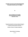
Figure 16: Left: flowchart for sending a message individually to every device. (also valid for
the CC2480 modules). Right: setup for the test. The coordinator is in red, the
end-devices in blue. The flashes symbolize sending messages successively to every
end-device. After one turn, the sequence begins again at the first device until having
completed 667 turns.
This situation has been simulated with the following approach (see fig. 16). There were
not 2000 modules available. As a workaround, the three end-devices have been contacted
one by one 667 times. This results in 2001 individual contacts. It turned out that this
procedure is very sensitive to the COM-Port settings. Table 4 shows the results of the
time consumption. If extra thread is set to yes, the application uses an extra thread
to read the acknowledge answers from the module. This reading works independent
from the sending command. The application doesn’t wait for the acknowledge before
it continues to send. If it is set to no, the applications sends the command to the first
module, waits then for the response and not until received it, it will send the command to
the next module. The reason for these different modes is that it has been discovered that
the time consumption differs widely. This indicates that a lot of improvements can be
realized with the application. These tests show already that it’s possible to reach times
in the region of 15 seconds. It’s also evident that the time consumption is reciprocally
proportional to the baud rate that has been used to communicate between the module
and the computer.
39
6 Tests and Evaluation
Baud Rate
[bps]
9600
9600
9600
9600
9600
9600
9600
9600
9600
9600
9600
57600
57600
57600
57600
57600
57600
57600
57600
57600
57600
57600
57600
extra thread
[boolean]
yes
yes
yes
yes
yes
yes
yes
yes
yes
yes
yes
yes
yes
yes
yes
yes
yes
no
no
no
no
no
no
command length
[bytes]
7
7
7
7
7
30
30
30
30
30
30
30
30
30
30
30
30
30
30
30
30
30
30
duration time
[sec]
33
33
34
33
33
81
81
81
81
81
81
13.49
13.49
13.48
13.74
13.49
13.49
31.98
31.95
31.98
31.97
32.02
31.97
Table 4: Different test-conditions for the Xbee Module
40
6.2 Test Scenarios with the CC2480 Modules
6.2 Test Scenarios with the CC2480 Modules
6.2.1 Broadcasting
Also with the CC2480 modules a network has been formed to perform some tests. Three
modules were available to form a network. One of the modules was the coordinator
sending the data. The first test consists again to send broadcast messages to all the enddevices. It was the same procedure like for the XBee modules (fig. 15). 288 messages
have been sent in a 5 minutes interval. This procedure has been repeated 5 times. All
of them have been received by all the end-devices.
6.2.2 Individual Addressing
While trying to perform the test by individual addressing it turned out that there is a
problem that increases the time consumption for sending data. First it has been formed
a network with one coordinator and two end-devices. While trying to record the time
consumption for sending 2000 messages it turned out that there are (relatively) long
pauses between the send request and the moment when the packed had been received
by the end-devices. This problem lies in an end-device specific way of communication:
End-devices in ZigBee are designed to be battery powered9 . Usually it’s thought that
end-devices can sleep most of the time. When something happens, they contact the
coordinator (like a automatic fire alarm, where the fire sensors are connected to the
end-devices). This means there is mainly a data transmission from the end-device to
the coordinator. To enable the end-device to receive data too by saving energy it doesn’t
listen all the time to the coordinator for receiving data. It actually polls the coordinator
for existing data. If the computer sends a send-data-request to the coordinator, the
coordinator stores the message an waits until the end-device in question polls for data.
Only now the data can be sent from the coordinator to the module. Even so the poll
rate can be varied and set to a minimal value of 1 millisecond.
In the first series of tests there has been sent 1000 times a message to each of the
two end-devices (simulating a contacting of 2000 nodes). The baud rate was set from
the beginning to 115200 bps and the poll time mentioned above was changed to the
minimum of 1 millisecond. The results are shown in table 5.
Table 5 shows that the time consumption for contacting 2000 nodes is about 2 minutes.
This takes too long as the telescope has to set its position every five minutes. This would
mean that it can only measure about 3 minutes in each position.
To check whether this long time is caused by the polling problem, the end-devices
have changed to work as routers. Routers are designed to be connected to a power
supply because they have to route data. Therefore they are always on and can receive
data immediately. In table 6 can be seen that with this configuration the procedure can
9
low power consumption is one of the design parameters of ZigBee
41
6 Tests and Evaluation
command length
[bytes]
1
23
30
duration time
[sec]
112
113
114
Table 5: individual addressing to end-devices
be accelerated dramatically. Contacting 2000 nodes needs then only about 45 seconds.
It has to kept in mind that this is not a way to realize the network in reality. In the
command length
[bytes]
1
1
1
1
30
30
30
30
duration time
[sec]
42
42
42
42
46
46
46
46
Table 6: individual addressing to routers
technical specifications of the CC2480 module it’s written that every parent device can
only have up to 6 routers as child devices.
6.3 Summarized Results
In principle it is possible to reach adequate fast speed to control up to 2000 motors.
Both possibilities (i.e. broadcasting or individual addressing) seem to be ways to realize
the wireless communication. In the case of using broadcasting there has to be thought
about ways to ensure that all modules receive the positioning commands.
One example to solve this problem is the usage of a watchdog timer. Every module has
to “know” how often it should receive a command. If the time expires without having
received a command, it can contact the coordinator for requesting it. The coordinator
will then send the command individually to only those modules that didn’t receive the
broadcast message.
Another way for having more control by using broadcasting is to send a counter
42
6.4 Conclusion and Open Questions
number with every command. The motors can compare all numbers coming from the
coordinator. If the difference of the numbers between two commands is bigger than 1,
the motor knows that it missed one command. In this case the motor can send a message
to the coordinator and then it’s known that one measurement will be not valid or at
least incomplete.
By using individual addressing, the best time that can be reached, really depends on
how the serial communication is implemented. It’s not sure whether the fastest possible
time has already been reached yet with the test applications. One crucial point is the
implementation of the communication between the computer (or the microprocessor)
and the rf data module. It depends not only on trivial settings like baud rate.
Furthermore there are also other ways to reduce the amount of data that has to
be sent. One can think about giving the end-devices more “intelligence”: a common
scenario for example is that the telescope has to go to a specific position and after that,
it has only to work against the earth rotation. In this case one could send a command
to the end-devices to turn to a specific point. After that, they end-devices have to move
the motors autonomously to correct earth rotation. In this case, there is no more data
needed to be sent. Only at the beginning there has to be sent data to each motor.
Looking at the tests with the CC2480 module, it’s difficult to say how fast a real
network can be. In 3.2 is has been showed that according to the CC2480 Developer’s
Guide it’s not possible to realize a simple star network with 2000 end-devices. The
network has to be subdivided to different branches with routers. With only three devices
it could’t be figured out how long the propagation of a data packet is taken from the
coordinator down to the last end-device (and the acknowledge back to the coordinator).
Furthermore there is the polling problem with the end-devices that increases the time
to control all nodes in a network. At least for the CC2480 module it has to be assumed
that controlling all motors by individual addressing takes longer in such a big network.
6.4 Conclusion and Open Questions
In the authors opinion the Xbee modules seem to be the better choice. With the firmware
that has been used, a simple star network can be formed. If individual addressing is
preferred, they are faster. The fact that data has not to be routed from the coordinator
to the end-device by other devices in the middle makes it easier to estimate how long
it takes to reach all nodes. Having no devices in between reduces the network load.
Another important point is that in a star network a corrupt device only affects the
corresponding mirror. But if a router in a cluster tree network has a malfunction, all
its child devices are separated from the coordinator unless dynamical reorganization is
implemented.
This thesis is a first clarification whether a wireless network can be a way to realize
the active mirror control of a telescope. There are still a lot of questions that have
to be answered. For instance no serious tests were performed to test the range of such
43
6 Tests and Evaluation
networks. According to the data sheets of the two tested modules it should be no problem
to handle distances given by the telescopes. With a battery powered test-board for the
XBee module it was possible to transmit data over a distance higher than 40 meters.
In this test was one module outdoors and one module indoors with a closed window in
between. With both modules outdoors is was possible to overcome distances about 60
meters.
Because of a design error in the PCB, the antenna-part of the CC2480 module was
not correctly working. With this modules it was only possible to transmit data over
a maximum distance about 4 meters. But this result has nothing to do with the real
values that could be reached.
It has also not been investigated how the real conditions, like a big metallic space
frame for mounting the mirrors, could affect the working range of those modules.
A next important step would be to test the network in more realistic conditions. This
means that one should build bigger networks to investigate how reliable the network is
when there are hundreds of devices with distances between each other that are comparable to the telescope dimensions. Especially when using the broadcast method one could
examine whether all end-devices still receive all messages or how often they miss one.
Such a network allows also to test how long it takes until the whole network is ready
after an electrical power outage for example.
44
References
References
[1] http://cta.physik.uzh.ch.
[2] http://www.cta-observatory.org.
[3] http://imagine.gsfc.nasa.gov/docs/science/how_l2/cerenkov.html.
[4] Bluetooth SIG, Inc., Specification of the Bluetooth System, BLUETOOTH SPECIFICATION Version 2.1 + EDR (vol 0), July 2007.
[5] M. Bürge, Standards drahtloser Übertragung: Von Bluetooth zu IEEE 802.15.4/ZigBee, 2004.
[6] http://de.wikipedia.org/wiki/IEEE_802.15.4.
[7] Digi International Inc., Xbee(R) / XBee-PRO(R) OEM RF Modules, Sept. 2008.
http://ftp1.digi.com/support/documentation/90000982_A.pdf.
[8] Texas Instruments, CC2480 Developer’s Guide SWRA176. http://focus.ti.com/
lit/an/swra176/swra176.pdf.
[9] Texas Instruments, CC2480 Interface Specification (Rev. A). http://focus.ti.
com/lit/er/swra175a/swra175a.pdf.
[10] http://www.cadsoft.de.
[11] National Semiconductors, LM2937-2.5, LM2937-3.3 400mA and 500mA Voltage
Regulators, Aug. 2005. http://www.national.com/ds/LM/LM2937-3.3.pdf.
[12] intersil, ICL3221ECAZ Data Sheet, Sept. 2008. http://www.intersil.com/data/
fn/fn4910.pdf.
45
C+
&
(
(+*
!""#
KG9
*
+
!
!/
$%&
!
!
+
*
6
8
9
1
7
0
!"
!!
!+
(!"
!""35
!/
(9
!:
4C,5
$%&
J!
(;8"*+<=
%(
%(
$G'D*
$G'D+
<C&L
IC&L
&4&&
$G'D!
$G'D"
C,<,F2%
(5$"
(5$!
+1:
**:
+
$%& $%&
(1
(7
$%&
(&A&DEF2,%A&D7
&FCA<),,G2CJA&'7
(F<A&'D1
CF<A-&9A&'D9
-<<D(A-&8A&'D8
C52F;A-&6A&'D6
(DDC&2<,)A-&*A&'D*
-&+A&'D+
-&!A&'D!
-&"A&'D"
(0
!6
!"
6
0
!+
!9
!8
!!
!1
!7
!0
+"
&'%A(D%5'$
&DEF
D%A<),,G
GHI"AC<<'
!""#
$%&
$%&
(8
!""#
*
+
!*
9
$%&
C!
89/
++"#
(*
-4&&2C5+
-4&&2<H
C52%
F;C;2<H'F(?
C52G
-4&&2C5!
-4&&2GC,
-4&&24(D
4(D2$E-C&
-4&&2(?G
C='-<+
-4&&2'5!
'(!
((+67"
$%&
!""#
*
*9
*8
*6
**
*+
*!
*"
+0
+7
+1
+9
+8
!""35
(+
!
+
*
KG+
)+
(6
!
+
*
KG6
!
+
*
KG*
C*
$%&
$%&
-%F!
6
!""#
(!*
$%&
!""#
(+!
!""#
(!!
!""#
(!1
!""#
(!6
$%&
!""#
(!
!
+
*
6
8
9
1
7
A,%
(!B
4B
(!@
(+B
(+@
4@
C!'%
8
6
A5DC(,D55
4((
$%&
F!DEF
5DC(,D%
F!'%
A'%4-)'&
C!DEF
'(+
'()*++!,(-.
A5DC(,D55
4((
$%&
F!DEF
5DC(,D%
F!'%
A'%4-)'&
C!DEF
!9
!8
!6
!*
!+
!!
!"
0
'%
$%&
'(*
'()*++!,(-.
$%&
A,%
(!B
4B
(!@
(+B
(+@
4@
C!'%
$%&
!
+
*
6
8
9
1
7
$%&
$%&
DEF
E+!"3+0*12**
(+"
(!7
4((
C,<,F
,;G
$%&
67
61
69
68
66
6*
6+
6!
6"
*0
*7
*1
%(67
<DAC;
&4&&61
<'AF;
%(69
<<A(F
%(68
(ACF
*+M2;D<(2J!
-"
*+M;D<(2J+
-!
&(DEG)
;D<(2J+
-4&&2&C,$
-4&&2<D( -4&&2&$E-C&
;D<(2J!
&4&&2-&(
C='-<!
-4&&2-&(
-4&&2CC,$
-4&&2'5+
CC,$2DEF
!""#
8
!9
!8
!6
!*
!+
!!
!"
0
!""#
(!0
&+
9
KG!
+
!
(!8
!
8
$%&
!>+:5
=
$%&
++#?
)6
)*
6*/
GN+
GN+
GN8
GN8
C!8
B
$%&
Figure 17: Circuit Diagram of the testboard
!*
!6
!8
!9
!1
!7
!0
+"
+!
++
+*
+6
$%&
)!
(+6
++#?
!":5
++#?
++#?
GN!
GN!
GN9
GN9
(++
$%&
)8
GN*
GN*
GN6
GN6
9>7#5
(!9
6
9
4((
!""#
*
(!+
+
!""#
46
!""#
-
!
$%&
KG8
6
*
+
!
;!@!
;!@+
;!@*
;!@6
;!@8
;!@9
;!@1
;!@7
;!@0
&
(
=
-
A Details of the PCB design
A Details of the PCB design
$%&
B
Figure 18: Picture of the unpopulated PCB
Figure 19: Picture of the populated PCB. The small IC on the upper right side is the CC2480
module, the blue on the lower right side is the XBee module.
47
B Listings
B Listings
B.1 Xbee Application
Form1.cs
using System ;
using System . C o l l e c t i o n s . G e n e r i c ;
using System . ComponentModel ;
using System . Data ;
using System . Drawing ;
using System . L i n q ;
using System . Text ;
using System . Windows . Forms ;
// von roman d a z u g e t a n
using System . T h r e a d i n g ;
namespace s e r i a l f u e r r o m a n
{
public p a r t i a l c l a s s Form1 : Form
{
// i n s t a n z v a r i a b e l n
B o o l e a n u s e A c t i o n H a n d l e r = true ;
APIControl a p i ;
String leseBuffer ;
ThreadStart del ;
Thread m y F i r s t T h r e a d ;
i n t anzahlRunden ;
// C o n s t r u c t o r
public Form1 ( )
{
// −−−−−−−−−−−−−−−−−−−−−−−−
// C o n s t r u c t o r
// −−−−−−−−−−−−−−−−−−−−−−−−
// GUI s t u f f ( g e n e r a t e d b y VS )
InitializeComponent () ;
// i n i t s e r i a l p o r t
s e r i a l P o r t 1 . BaudRate = 5 7 6 0 0 ;
// s e r i a l P o r t 1 . PortName = ”COM1” ;
s e r i a l P o r t 1 . P a r i t y = System . IO . P o r t s . P a r i t y . None ;
s e r i a l P o r t 1 . Handshake = System . IO . P o r t s . Handshake . None ;
s e r i a l P o r t 1 . S t o p B i t s = System . IO . P o r t s . S t o p B i t s . One ;
s e r i a l P o r t 1 . DataBits = 8 ;
// s e r i a l P o r t 1 .
// add E v e n t H a n d l e r t o s e r i a l p o r t ( r e c i e v e )
s e r i a l P o r t 1 . D a t a R e c e i v e d += new System . IO . P o r t s . S e r i a l D a t a R e c e i v e d E v e n t H a n d l e r (
serialPort1 DataReceived ) ;
// s e r i a l P o r t 1 . Open ( ) ;
t h i s . a p i = new APIControl ( s e r i a l P o r t 1 ,
// roman v e r s u c h t
textBox1 ) ;
multithreading
}
// E v e n t h a n d l e r f o r D a t a R e c e i v e d
void s e r i a l P o r t 1 D a t a R e c e i v e d ( o b j e c t s e n d e r , System . IO . P o r t s .
SerialDataReceivedEventArgs e )
{
// −−−−−−−−−−−−−−−−−−−−−−−−
// E v e n t H a n d l e r f o r s e r i a l p o r t 1 D a t a R e c i e v e d E v e n t
// −−−−−−−−−−−−−−−−−−−−−−−−
// d i r t y h a c k , s e r i a l p o r t e v e n t r u n s i n d i f f e r e n t t h r e a d w h i c h
access gui elements ; next l i n e enables t h i s
CheckForIllegalCrossThreadCalls = false ;
// r e a d a l l a v a i l a b l e d a t a and a p p e n d i t t o t h e t e x t b o x
S t r i n g neues = s e r i a l P o r t 1 . ReadExisting ( ) ;
t e x t B o x 1 . Text = t e x t B o x 1 . Text + n e u e s ;
// t e x t B o x 1 . T e x t = t e x t B o x 1 . T e x t + s e r i a l P o r t 1 . R e a d E x i s t i n g ( ) ;
}
48
is
not
allowed
to
B.1 Xbee Application
// r e a d c u r r e n t s e t t i n g s o f a d e v i c e and s e t t h e c h e c k b o x e s
p r i v a t e void r e a d C u r r e n t S e t t i n g s ( )
{
Boolean s t a t u s ;
String result ;
// n o r m a l e n e v e n t h a n d l e r e n t f e r n e n
s e r i a l P o r t 1 . D a t a R e c e i v e d −= new System . IO . P o r t s . S e r i a l D a t a R e c e i v e d E v e n t H a n d l e r (
serialPort1 DataReceived ) ;
useActionHandler = false ;
try
{
// e n t e r i n g command mode
System . T h r e a d i n g . Thread . S l e e p ( 1 1 0 0 ) ;
s e r i a l P o r t 1 . Write ( ”+++” ) ;
System . T h r e a d i n g . Thread . S l e e p ( 1 1 0 0 ) ;
serialPort1 . DiscardInBuffer () ;
s e r i a l P o r t 1 . Write ( ”ATMY\ r ” ) ;
t e x t B o x 3 . Text = s e r i a l P o r t 1 . ReadTo ( ” \ r ” ) ;
serialPort1 . DiscardInBuffer () ;
s e r i a l P o r t 1 . Write ( ”ATDH\ r ” ) ;
t e x t B o x 4 . Text = s e r i a l P o r t 1 . ReadTo ( ” \ r ” ) ;
serialPort1 . DiscardInBuffer () ;
s e r i a l P o r t 1 . Write ( ”ATDL\ r ” ) ;
t e x t B o x 5 . Text = s e r i a l P o r t 1 . ReadTo ( ” \ r ” ) ;
serialPort1 . DiscardInBuffer () ;
s e r i a l P o r t 1 . Write ( ”ATCE\ r ” ) ;
r e s u l t = s e r i a l P o r t 1 . ReadTo ( ” \ r ” ) ;
i f ( r e s u l t . Contains ( ”0” ) )
{
checkBox1 . Checked = f a l s e ;
}
else
{
checkBox1 . Checked = true ;
}
serialPort1 . DiscardInBuffer () ;
s e r i a l P o r t 1 . Write ( ”ATA2\ r ” ) ;
r e s u l t = s e r i a l P o r t 1 . ReadTo ( ” \ r ” ) ;
i f ( r e s u l t . Contains ( ”2” ) )
{
checkBox2 . Checked = f a l s e ;
}
else
{
checkBox2 . Checked = true ;
}
// l e a v e command mode
s e r i a l P o r t 1 . Write ( ”ATCN\ r ” ) ;
}
catch ( E x c e p t i o n e x c e p )
{
MessageBox . Show ( ”You must f i r s t c h o o s e an unused COM P o r t . ” , ” S e r i a l I n t e r f a c e
Error ” ,
MessageBoxButtons .OK, Mes sage BoxI con . E x c l a m a t i o n ) ;
}
// n o r m a l e v e n t h a n d l e r w i e d e r a k t i v i e r e n
s e r i a l P o r t 1 . D a t a R e c e i v e d += new System . IO . P o r t s . S e r i a l D a t a R e c e i v e d E v e n t H a n d l e r (
serialPort1 DataReceived ) ;
u s e A c t i o n H a n d l e r = true ;
}
// o p e n s new c o m p o r t
p r i v a t e void changeComport ( S t r i n g
{
s e r i a l P o r t 1 . Close () ;
s e r i a l P o r t 1 . PortName = p o r t ;
try
port ,
RadioButton b u t t o n )
49
B Listings
{
s e r i a l P o r t 1 . Open ( ) ;
t e x t B o x 1 . Text = t e x t B o x 1 . Text + ” \ r \ ncomport changed t o ” + p o r t + ” \ r \n” ;
}
catch ( E x c e p t i o n e x c e p )
{
MessageBox . Show ( ” F a i l e d t o open ” + p o r t + ” . \ nMaybe i t ’ s
S e r i a l I n t e r f a c e Error ” ,
MessageBoxButtons .OK, Mes sage BoxI con . E x c l a m a t i o n ) ;
b u t t o n . Checked = f a l s e ;
already
in
use . ” , ”
}
}
// s e n d s a t commands t o t h e s e r i a l p o r t
p r i v a t e void sendSerialCommand ( S t r i n g command )
{
try
{
// new l i n e i n S t a t u s t e x t f i e l d
t e x t B o x 1 . Text = t e x t B o x 1 . Text + ” \ r \n” ;
// e n t e r i n g command mode
System . T h r e a d i n g . Thread . S l e e p ( 1 1 0 0 ) ;
s e r i a l P o r t 1 . Write ( ”+++” ) ;
System . T h r e a d i n g . Thread . S l e e p ( 1 1 0 0 ) ;
// s e n d commands
s e r i a l P o r t 1 . Write ( command + ” \ r ” ) ;
// e x i t a t command mode
s e r i a l P o r t 1 . Write ( ”ATCN\ r \n” ) ;
}
catch ( E x c e p t i o n e )
{
MessageBox . Show ( ”You must f i r s t c h o o s e an unused COM P o r t . ” , ” S e r i a l
Error ” ,
MessageBoxButtons .OK, Mes sage BoxI con . E x c l a m a t i o n ) ;
Interface
}
}
p r i v a t e void s e n d S e r i a l D a t a L i n e ( S t r i n g d a t a )
{
try
{
s e r i a l P o r t 1 . Write ( d a t a + ” \ r \n” ) ;
}
catch ( E x c e p t i o n e )
{
MessageBox . Show ( ”You must f i r s t c h o o s e an unused COM P o r t . ” , ” S e r i a l
Error ” ,
MessageBoxButtons .OK, Mes sage BoxI con . E x c l a m a t i o n ) ;
}
}
p r i v a t e void b t n S t a t u s C l i c k ( o b j e c t s e n d e r , EventArgs e )
{
// −−−−−−−−−−−−−−−−−−−−−−−−
// s t a t u s b u t t o n c a l l b a c k
// −−−−−−−−−−−−−−−−−−−−−−−−
// s e n d command s e q u e n c e t o c h i p ( w r i t e l i n e a u t o m a t i c a l l y
t e x t B o x 1 . Text = t e x t B o x 1 . Text + ” \ r \n” ;
sendSerialCommand ( ”ATSH, SL” ) ;
}
// s e n d s t r i n g t o s e l e c t e d c o m p o r t
p r i v a t e void b u t t o n 1 C l i c k ( o b j e c t s e n d e r ,
{
s e n d S e r i a l D a t a L i n e ( t e x t B o x 2 . Text ) ;
50
EventArgs e )
a p p e n d s \ r \n ,
Interface
eg
newline )
B.1 Xbee Application
}
// The r a d i o b u t t o n s
p r i v a t e void r a d i o B u t t o n 1 C h e c k e d C h a n g e d ( o b j e c t s e n d e r ,
{
i f ( r a d i o B u t t o n 1 . Checked )
{
changeComport ( ”COM1” , r a d i o B u t t o n 1 ) ;
}
EventArgs e )
}
p r i v a t e void r a d i o B u t t o n 2 C h e c k e d C h a n g e d ( o b j e c t s e n d e r ,
{
i f ( r a d i o B u t t o n 2 . Checked )
{
changeComport ( ”COM4” , r a d i o B u t t o n 2 ) ;
}
}
EventArgs e )
p r i v a t e void r a d i o B u t t o n 3 C h e c k e d C h a n g e d ( o b j e c t s e n d e r ,
{
i f ( r a d i o B u t t o n 3 . Checked )
{
changeComport ( ”COM2” , r a d i o B u t t o n 3 ) ;
}
}
// end o f t h e r a d i o b u t t o n s
EventArgs e )
// c l e a r t h e t e x t b o x
p r i v a t e void b u t t o n 2 C l i c k ( o b j e c t s e n d e r ,
{
t e x t B o x 1 . Text = ” ” ;
}
EventArgs e )
// s e t t i n g t h e c o o r d i n a t o r modus
p r i v a t e void checkBox1 CheckedChanged ( o b j e c t s e n d e r , EventArgs e )
{
i f ( useActionHandler )
{
i f ( checkBox1 . Checked )
// e n a b l e c o o r d i n a t o r mode
{
sendSerialCommand ( ”ATCE1” ) ;
}
else
// d i s a b l e c o o r d i n a t o r mode
{
sendSerialCommand ( ”ATCE0” ) ;
}
}
}
// c h e c k b o x ” a l l o w a s s o c i a t i o n ”
p r i v a t e void checkBox2 CheckedChanged ( o b j e c t s e n d e r , EventArgs e )
{
i f ( useActionHandler )
{
i f ( checkBox2 . Checked )
// a l l o w a s s o c i a t i o n
{
sendSerialCommand ( ”ATA26” ) ;
}
e l s e // d i s a b l e a s s o c i a t i o n
{
sendSerialCommand ( ”ATA22” ) ;
}
}
}
// s e t my a d r e s s
p r i v a t e void b u t t o n 3 C l i c k ( o b j e c t s e n d e r , EventArgs e )
{
S t r i n g command = ”ATMY” + t e x t B o x 3 . Text ;
sendSerialCommand ( command ) ;
}
51
B Listings
// s e t DH a d r e s s
p r i v a t e void b u t t o n 4 C l i c k ( o b j e c t s e n d e r , EventArgs e )
{
S t r i n g command = ”ATDH” + t e x t B o x 4 . Text ;
sendSerialCommand ( command ) ;
}
// s e t DL a d r e s s
p r i v a t e void b u t t o n 5 C l i c k ( o b j e c t s e n d e r , EventArgs e )
{
S t r i n g command = ”ATDL” + t e x t B o x 5 . Text ;
sendSerialCommand ( command ) ;
}
// e n a b l e b r o a d c a s t i n g
p r i v a t e void b u t t o n 6 C l i c k ( o b j e c t s e n d e r ,
{
S t r i n g command = ”ATDLFFFF, DH0” ;
sendSerialCommand ( command ) ;
}
// r e a d MY A d r e s s
p r i v a t e void b u t t o n 7 C l i c k ( o b j e c t s e n d e r ,
{
sendSerialCommand ( ”ATMY” ) ;
/∗
// b e g i n romans t e s t
string [] fenster ;
f e n s t e r = textBox1 . Text . S p l i t ( ’\ r ’ ) ;
int groesse ;
g r o e s s e = f e n s t e r . GetLength (0) ;
// end romans t e s t
∗/
}
// r e a d DH
p r i v a t e void b u t t o n 8 C l i c k ( o b j e c t s e n d e r ,
{
sendSerialCommand ( ”ATDH” ) ;
}
// r e a d DL
p r i v a t e void b u t t o n 9 C l i c k ( o b j e c t s e n d e r ,
{
sendSerialCommand ( ”ATDL” ) ;
}
EventArgs e )
EventArgs e )
EventArgs e )
EventArgs e )
// B r o a d c a s t t e s t
p r i v a t e void b u t t o n 1 0 C l i c k ( o b j e c t s e n d e r , EventArgs e )
{
try
{
i n t z a h l e r = C o n v e r t . T o I n t 3 2 ( t e x t B o x 6 . Text ) ;
i n t i n t e r v a l l = C o n v e r t . T o I n t 3 2 ( t e x t B o x 8 . Text ) ∗ 1 0 0 0 ;
s e n d S e r i a l D a t a L i n e ( ” B r o a d c a s t i n g the message ” + z a h l e r + ” times ” ) ;
f o r ( i n t i = 0 ; i < z a h l e r ; i ++)
{
s e n d S e r i a l D a t a L i n e ( ” B r o a d c a s t m e s s a g e Nr . ” + ( i +1) + ” ” + DateTime . Now .
ToShortTimeString ( ) ) ;
Thread . S l e e p ( i n t e r v a l l ) ;
}
}
catch ( E x c e p t i o n e x c e p )
{
MessageBox . Show ( ” you must e n t e r an i n t e g e r . ” , ” P a r s i n g E r r o r ” ,
MessageBoxButtons .OK, Mes sage BoxI con . E x c l a m a t i o n ) ;
}
}
// m a n u a l l y r e a d c u r r e n t s e t t i n g s
p r i v a t e void b u t t o n 1 1 C l i c k ( o b j e c t s e n d e r ,
{
readCurrentSettings () ;
}
// s e n d g i v e n command
p r i v a t e void b u t t o n 1 2 C l i c k ( o b j e c t s e n d e r ,
52
EventArgs e )
EventArgs e )
B.1 Xbee Application
{
sendSerialCommand ( t e x t B o x 7 . Text ) ;
}
p r i v a t e void b u t t o n 1 3 C l i c k ( o b j e c t s e n d e r ,
{
EventArgs e )
d e l = new T h r e a d S t a r t ( t h r e a d r e c ) ;
m y F i r s t T h r e a d = new Thread ( d e l ) ;
//
t h i s . s e n d S e r i a l C o m m a n d ( ”ATAP1” ) ;
// n o r m a l e n e v e n t h a n d l e r e n t f e r n e n machen
// s e r i a l P o r t 1 . D a t a R e c e i v e d −= new S y s t e m . IO . P o r t s . S e r i a l D a t a R e c e i v e d E v e n t H a n d l e r (
serialPort1 DataReceived ) ;
// d e b u g e v e n t h a n d l e r e i n s c h a l t e n
// s e r i a l P o r t 1 . D a t a R e c e i v e d += new S y s t e m . IO . P o r t s . S e r i a l D a t a R e c e i v e d E v e n t H a n d l e r (
debug eventhandler ) ;
anzahlRunden = C o n v e r t . T o I n t 3 2 ( t e x t B o x 9 . Text ) ;
// t e x t B o x 1 . T e x t = t e x t B o x 1 . T e x t + ”\ r \n Ohne A n t w o r t
DateTime s t a r t Z e i t = DateTime . Now ;
DateTime s t o p Z e i t ;
auslesen ”;
t e x t B o x 1 . Text = t e x t B o x 1 . Text + ” \ r \ n S t a r t t i m e : ” + s t a r t Z e i t . ToLongTimeString ( ) ;
//
DateTime . Now . T o L o n g T i m e S t r i n g ( ) ;
// i f ( ! m y F i r s t T h r e a d . I s A l i v e ) m y F i r s t T h r e a d . S t a r t ( ) ;
myFirstThread . S t a r t ( ) ;
while ( ! m y F i r s t T h r e a d . I s A l i v e )
{
// w a r t e , b i s e r l a e u f t
}
l e s e B u f f e r = ”” ;
f o r ( i n t i = 0 ; i <anzahlRunden ; i ++)
{
a p i . t r a n s m i t D a t a ( 0 x00 , 0 x01 , 0 x00 , new byte [ ] { 0 x43 , 0 x48 , 0 x49 , 0 x50 , 0 x30 , 0
x5B , 0x5D , 0 x43 , 0 x48 , 0 x49 , 0 x50 , 0 x30 , 0x5B , 0x5D , 0 x43 , 0 x48 , 0 x49 , 0
x50 , 0 x30 , 0x5B , 0x5D , 0 x43 , 0 x48 , 0 x49 , 0 x50 , 0 x30 , 0x5B , 0x5D , 0x0D , 0
x0A } ) ;
// t h i s . r e a d B y t e ( 7 , t r u e ) ;
a p i . t r a n s m i t D a t a ( 0 x00 , 0 x02 , 0 x00 , new byte [ ] { 0 x43 , 0 x48 , 0 x49 , 0 x50 , 0 x32 , 0
x5B , 0x5D , 0 x43 , 0 x48 , 0 x49 , 0 x50 , 0 x32 , 0x5B , 0x5D , 0 x43 , 0 x48 , 0 x49 , 0
x50 , 0 x32 , 0x5B , 0x5D , 0 x43 , 0 x48 , 0 x49 , 0 x50 , 0 x32 , 0x5B , 0x5D , 0x0D , 0
x0A } ) ;
// t h i s . r e a d B y t e ( 7 , t r u e ) ;
a p i . t r a n s m i t D a t a ( 0 x00 , 0 x03 , 0 x00 , new byte [ ] { 0 x43 , 0 x48 , 0 x49 , 0 x50 , 0 x31 , 0
x5B , 0x5D , 0 x43 , 0 x48 , 0 x49 , 0 x50 , 0 x31 , 0x5B , 0x5D , 0 x43 , 0 x48 , 0 x49 , 0
x50 , 0 x31 , 0x5B , 0x5D , 0 x43 , 0 x48 , 0 x49 , 0 x50 , 0 x31 , 0x5B , 0x5D , 0x0D , 0
x0A } ) ;
// t h i s . r e a d B y t e ( 7 , t r u e ) ;
}
s t o p Z e i t = DateTime . Now ;
t e x t B o x 1 . Text = t e x t B o x 1 . Text + ” \ r \ nStop
t i m e : ” + s t o p Z e i t . ToLongTimeString ( ) ;
t e x t B o x 1 . Text = t e x t B o x 1 . Text + ” \ r \ n D i f f e r e n z : ” + s t o p Z e i t . S u b t r a c t ( s t a r t Z e i t ) .
T o S t r i n g ( ) + ” \ r \n” ;
// d e b u g e v e n t h a n d l e r d e a k t i v i e r e n
// s e r i a l P o r t 1 . D a t a R e c e i v e d −= new S y s t e m . IO . P o r t s . S e r i a l D a t a R e c e i v e d E v e n t H a n d l e r (
debug eventhandler ) ;
// n o r m a l e v e n t h a n d l e r w i e d e r a k t i v i e r e n
// s e r i a l P o r t 1 . D a t a R e c e i v e d += new S y s t e m . IO . P o r t s . S e r i a l D a t a R e c e i v e d E v e n t H a n d l e r (
serialPort1 DataReceived ) ;
myFirstThread . J o i n ( ) ;
// n o r m a l e v e n t h a n d l e r w i e d e r a k t i v i e r e n
s e r i a l P o r t 1 . D a t a R e c e i v e d += new System . IO . P o r t s . S e r i a l D a t a R e c e i v e d E v e n t H a n d l e r (
serialPort1 DataReceived ) ;
// s e n d S e r i a l C o m m a n d ( ”ATAP0” ) ;
}
53
B Listings
p r i v a t e void r e a d B y t e ( i n t a n z a h l , bool a n z e i g e n )
{
byte [ ] a n s w e r = new byte [ a n z a h l ] ;
f o r ( i n t i = 0 ; i < a n z a h l ; i ++)
{
a n s w e r [ i ] = ( byte ) s e r i a l P o r t 1 . ReadByte ( ) ;
}
if
( a n z e i g e n ) t e x t B o x 1 . Text = t e x t B o x 1 . Text + ” \ r \n” + System . B i t C o n v e r t e r . T o S t r i n g
( answer ) ;
}
p r i v a t e void b u t t o n 1 4 C l i c k ( o b j e c t s e n d e r , EventArgs e )
{
// n o r m a l e n e v e n t h a n d l e r e n t f e r n e n machen
s e r i a l P o r t 1 . D a t a R e c e i v e d −= new System . IO . P o r t s . S e r i a l D a t a R e c e i v e d E v e n t H a n d l e r (
serialPort1 DataReceived ) ;
anzahlRunden = C o n v e r t . T o I n t 3 2 ( t e x t B o x 9 . Text ) ;
DateTime s t a r t Z e i t = DateTime . Now ;
DateTime s t o p Z e i t ;
t e x t B o x 1 . Text = t e x t B o x 1 . Text + ” \ r \ n S t a r t t i m e : ” + s t a r t Z e i t . ToLongTimeString ( ) ;
//
DateTime . Now . T o L o n g T i m e S t r i n g ( ) ;
l e s e B u f f e r = ”” ;
serialPort1 . DiscardInBuffer () ;
f o r ( i n t i = 0 ; i < anzahlRunden ; i ++)
{
a p i . t r a n s m i t D a t a ( 0 x00 , 0 x01 , 0 x00 , new byte [ ] { 0 x43 , 0 x48 , 0 x49 , 0 x50 , 0 x30 , 0
x5B , 0x5D , 0 x43 , 0 x48 , 0 x49 , 0 x50 , 0 x30 , 0x5B , 0x5D , 0 x43 , 0 x48 , 0 x49 , 0
x50 , 0 x30 , 0x5B , 0x5D , 0 x43 , 0 x48 , 0 x49 , 0 x50 , 0 x30 , 0x5B , 0x5D , 0x0D , 0
x0A } ) ;
this . readByte ( 7 , f a l s e ) ;
a p i . t r a n s m i t D a t a ( 0 x00 , 0 x02 , 0 x00 , new byte [ ] { 0 x43 , 0 x48 , 0 x49 , 0 x50 , 0 x32 , 0
x5B , 0x5D , 0 x43 , 0 x48 , 0 x49 , 0 x50 , 0 x32 , 0x5B , 0x5D , 0 x43 , 0 x48 , 0 x49 , 0
x50 , 0 x32 , 0x5B , 0x5D , 0 x43 , 0 x48 , 0 x49 , 0 x50 , 0 x32 , 0x5B , 0x5D , 0x0D , 0
x0A } ) ;
this . readByte ( 7 , f a l s e ) ;
a p i . t r a n s m i t D a t a ( 0 x00 , 0 x03 , 0 x00 , new byte [ ] { 0 x43 , 0 x48 , 0 x49 , 0 x50 , 0 x31 , 0
x5B , 0x5D , 0 x43 , 0 x48 , 0 x49 , 0 x50 , 0 x31 , 0x5B , 0x5D , 0 x43 , 0 x48 , 0 x49 , 0
x50 , 0 x31 , 0x5B , 0x5D , 0 x43 , 0 x48 , 0 x49 , 0 x50 , 0 x31 , 0x5B , 0x5D , 0x0D , 0
x0A } ) ;
this . readByte ( 7 , f a l s e ) ;
}
s t o p Z e i t = DateTime . Now ;
t e x t B o x 1 . Text = t e x t B o x 1 . Text + ” \ r \ nStop
t i m e : ” + s t o p Z e i t . ToLongTimeString ( ) ;
t e x t B o x 1 . Text = t e x t B o x 1 . Text + ” \ r \ n D i f f e r e n z : ” + s t o p Z e i t . S u b t r a c t ( s t a r t Z e i t ) .
T o S t r i n g ( ) + ” \ r \n” ;
// n o r m a l e v e n t h a n d l e r w i e d e r a k t i v i e r e n
s e r i a l P o r t 1 . D a t a R e c e i v e d += new System . IO . P o r t s . S e r i a l D a t a R e c e i v e d E v e n t H a n d l e r (
serialPort1 DataReceived ) ;
// s e n d S e r i a l C o m m a n d ( ”ATAP0” ) ;
}
void d e b u g e v e n t h a n d l e r ( o b j e c t s e n d e r , System . IO . P o r t s . S e r i a l D a t a R e c e i v e d E v e n t A r g s e )
{
// −−−−−−−−−−−−−−−−−−−−−−−−
// E v e n t H a n d l e r f o r s e r i a l p o r t 1 D a t a R e c i e v e d E v e n t
// −−−−−−−−−−−−−−−−−−−−−−−−
// d i r t y h a c k , s e r i a l p o r t e v e n t r u n s i n d i f f e r e n t t h r e a d w h i c h i s n o t a l l o w e d t o
access gui elements ; next l i n e enables t h i s
CheckForIllegalCrossThreadCalls = false ;
// t e x t B o x 1 . T e x t = t e x t B o x 1 . T e x t + ” A c t i o n h a n d l e r f i r e d ” ;
// i n t a n z a h l = s e r i a l P o r t 1 . BytesToRead ;
// b y t e [ ] a n s w e r = new b y t e [ a n z a h l ] ;
// f o r ( i n t i = 0 ; i < a n z a h l ; i ++)
// {
//
answer [ i ] = ( b y t e ) s e r i a l P o r t 1 . ReadByte ( ) ;
//
i f ( a n s w e r [ i ] == 0 x7E ) t e x t B o x 1 . T e x t = t e x t B o x 1 . T e x t + ”\ r \n ” ;
//
t e x t B o x 1 . T e x t = t e x t B o x 1 . T e x t + ”−” + a n s w e r [ i ] . T o S t r i n g ( ”X” ) ;
54
B.1 Xbee Application
// }
l e s e B u f f e r = l e s e B u f f e r + s e r i a l P o r t 1 . ReadExisting ( ) ;
// t e x t B o x 1 . T e x t = t e x t B o x 1 . T e x t + S y s t e m . B i t C o n v e r t e r . T o S t r i n g ( a n s w e r ) ;
}
public void t h r e a d r e c ( )
{
CheckForIllegalCrossThreadCalls = false ;
// n o r m a l e n e v e n t h a n d l e r e n t f e r n e n machen
s e r i a l P o r t 1 . D a t a R e c e i v e d −= new System . IO . P o r t s . S e r i a l D a t a R e c e i v e d E v e n t H a n d l e r (
serialPort1 DataReceived ) ;
serialPort1 . DiscardInBuffer () ;
// g e r u e m p e l i g n o r i e r e n
i n t gotAck = 0 ;
i n t a n z a h l L e s e r u n d e n = 3 ∗ anzahlRunden ;
// e i n l e s e n a l l e r a n t w o r t e n
byte [ , ] a n s w e r = new byte [ a n z a h l L e s e r u n d e n , 7 ] ;
t e x t B o x 1 . Text = t e x t B o x 1 . Text + ” \ r \n” ;
f o r ( i n t i = 0 ; i < a n z a h l L e s e r u n d e n ; i ++)
{
f o r ( i n t j = 0 ; j < 7 ; j ++)
{
a n s w e r [ i , j ] = ( byte ) s e r i a l P o r t 1 . ReadByte ( ) ;
}
}
// u e b e r p r u e f e s t a t u s b y t e
f o r ( i n t i = 0 ; i < a n z a h l L e s e r u n d e n ; i ++)
{
i f ( a n s w e r [ i , 5 ] == ( byte ) 0 x00 ) gotAck++;
}
t e x t B o x 1 . Text = t e x t B o x 1 . Text + ” \ r \n” + ” Anzahl Antwort en : ” + gotAck ;
// // m y F i r s t T h r e a d . S
// f o r ( i n t i = 0 ; i < a n z a h l L e s e r u n d e n ; i ++)
// {
//
f o r ( i n t j = 0 ; j < 7 ; j ++)
//
{
//
t e x t B o x 1 . Text = t e x t B o x 1 . Text + answer [ i ,
//
// }
j ] . T o S t r i n g ( ”X” ) ;
}
}
}
}
55
B Listings
APIControl.cs
using
using
using
using
System ;
System . C o l l e c t i o n s . G e n e r i c ;
System . L i n q ;
System . Text ;
namespace s e r i a l f u e r r o m a n
{
c l a s s APIControl
{
// i n s t a n t z v a r i a b e l n
System . IO . P o r t s . S e r i a l P o r t s e r i a l P o r t 1 ;
System . Windows . Forms . TextBox box ;
byte s t a r t D e l i m i t e r ;
// k o n s t r u k t o r m e t h o d e
public APIControl ( System . IO . P o r t s . S e r i a l P o r t
box )
{
this . s e r i a l P o r t 1 = s e r i a l P o r t 1 ;
t h i s . box = box ;
t h i s . s t a r t D e l i m i t e r = 0x7E ;
}
// r e t u r n s c h e c k s u m f r o m a f r a m e a r r a y
p r i v a t e byte checkSum ( byte [ ] f r a m e )
{
byte summe = 0 x00 ;
f o r ( i n t i = 0 ; i < f r a m e . Length ;
{
summe += f r a m e [ i ] ;
}
serialPort1 ,
System . Windows . Forms . TextBox
i ++)
byte r e s u l t = ( byte ) ( ( byte ) 0xFF − summe ) ;
return r e s u l t ;
}
// s e n d a command t o t h e s e r i a l i n t e r f a c e
public void sendCommand ( byte [ ] l e n g t h , byte [ ] f r a m e )
{
byte [ ] b u f f e r = new byte [ 4 + f r a m e . Length ] ;
buffer [0] = startDelimiter ;
buffer [ 1 ] = length [ 0 ] ;
buffer [ 2 ] = length [ 1 ] ;
f r a m e . CopyTo ( b u f f e r , 3 ) ;
b u f f e r [ b u f f e r . Length −1] = t h i s . checkSum ( f r a m e ) ;
s e r i a l P o r t 1 . Write ( b u f f e r , 0 , b u f f e r . Length ) ;
}
public void t r a n s m i t D a t a ( byte dh , byte d l , byte opt , byte [ ]
{
byte [ ] f r a m e = new byte [ 5 + d a t a . Length ] ;
byte [ ] l e n g t h = new byte [ 2 ] ;
l e n g t h [ 0 ] = 0 x00 ;
f r a m e [ 0 ] = 0 x01 ;
f r a m e [ 1 ] = 0 x52 ; // f r a m e i d
f r a m e [ 2 ] = dh ;
frame [ 3 ] = d l ;
f r a m e [ 4 ] = o p t ; // o p t i o n b i t
d a t a . CopyTo ( frame , 5 ) ;
??
l e n g t h [ 1 ] = ( byte ) f r a m e . Length ;
t h i s . sendCommand ( l e n g t h , f r a m e ) ;
}
public void leaveApiMode ( )
{
byte [ ] f r a m e = new byte [ 5 ] ;
f r a m e [ 0 ] = 0 x08 ;
f r a m e [ 1 ] = 0 x52 ;
f r a m e [ 2 ] = 0 x41 ; //A
f r a m e [ 3 ] = 0 x50 ; //P
f r a m e [ 4 ] = 0 x30 ; // 0 n u l l
byte [ ] l e n g t h = {0 x00 , 0 x05 } ;
56
data )
B.1 Xbee Application
t h i s . sendCommand ( l e n g t h ,
frame ) ;
}
}
}
57
B Listings
B.2 CC2480 Application
Form1.cs
using
using
using
using
using
using
using
using
using
using
System ;
System . C o l l e c t i o n s . G e n e r i c ;
System . ComponentModel ;
System . Data ;
System . Drawing ;
System . L i n q ;
System . Text ;
System . Windows . Forms ;
System . T h r e a d i n g ;
System . IO ;
namespace WindowsFormsApplication1
{
public p a r t i a l c l a s s Form1 : Form
{
// i n s t a n z v a r i a b e l n
CCComands c c c o n t r o l ;
bool u s e E v e n t H a n d l e r ;
i n t runden ;
public Form1 ( )
{
// C o n s t r u c t o r
InitializeComponent () ;
// k o m m a n d o c l a s s e n o b j e k t machen
//
t h i s . c c c o n t r o l = new CCComands ( s e r i a l P o r t 1 ,
u s e E v e n t H a n d l e r = true ;
textBox1 ) ;
}
// E v e n t h a n d l e r , wenn was gekommen i s t .
void s e r i a l P o r t 1 D a t a R e c e i v e d ( o b j e c t s e n d e r ,
SerialDataReceivedEventArgs e )
{
System . IO . P o r t s .
// −−−−−−−−−−−−−−−−−−−−−−−−
// E v e n t H a n d l e r f o r s e r i a l p o r t 1 D a t a R e c i e v e d E v e n t
// −−−−−−−−−−−−−−−−−−−−−−−−
// d i r t y h a c k , s e r i a l p o r t e v e n t r u n s i n d i f f e r e n t t h r e a d w h i c h
access gui elements ; next l i n e enables t h i s
CheckForIllegalCrossThreadCalls = false ;
// t e x t B o x 1 . T e x t = t e x t B o x 1 . T e x t + ” A c t i o n h a n d l e r f i r e d ” ;
is
not
i n t a n z a h l = s e r i a l P o r t 1 . BytesToRead ;
byte [ ] a n s w e r = new byte [ a n z a h l ] ;
f o r ( i n t i = 0 ; i < a n z a h l ; i ++)
{
a n s w e r [ i ] = ( byte ) s e r i a l P o r t 1 . ReadByte ( ) ;
i f ( a n s w e r [ i ] == 0xFE ) t e x t B o x 1 . Text = t e x t B o x 1 . Text + ” \ r \n” ;
}
t e x t B o x 1 . Text = t e x t B o x 1 . Text + System . B i t C o n v e r t e r . T o S t r i n g ( a n s w e r ) ;
}
// b u t t o n 1 f o r d e b u g g i n g
p r i v a t e void b u t t o n 1 C l i c k ( o b j e c t s e n d e r , EventArgs e )
{
// b y t e [ ] command = { 1 , 2 , 3 } ;
byte c o n f i g I D = 0 x24 ;
byte l e n = 0 x02 ;
byte [ ] v a l u e = {0 x01 , 0 x00 } ;
byte v a l 0 = 0 x01 ;
byte v a l 1 = 0 x00 ;
c c c o n t r o l . z b w r i t e c o n f i g u r a t i o n ( configID , len , value ) ;
}
58
allowed
to
B.2 CC2480 Application
// b u t t o n r f t e s t
p r i v a t e void b u t t o n 2 C l i c k ( o b j e c t s e n d e r , EventArgs e )
{
// g e t d e v i c e i n f o
// b y t e [ ] a n s w e r = c c c o n t r o l . z b r e a d c o n f i g u r a t i o n ( 0 x 0 3 ) ;
// t e x t B o x 2 . T e x t = S y s t e m . B i t C o n v e r t e r . T o S t r i n g ( a n s w e r ) ;
t e x t B o x 1 . Text = t e x t B o x 1 . Text + ” t e s t 1 \ r \n” ;
c c c o n t r o l . t e s t r f ( 0 x00 , 0 x00 , 0 x9F ) ;
t e x t B o x 1 . Text = t e x t B o x 1 . Text + ” t e s t 2 \ r \n” ;
c c c o n t r o l . t e s t r f ( 0 x01 , 0 x00 , 0 x9F ) ;
t e x t B o x 1 . Text = t e x t B o x 1 . Text + ” t e s t 3 \ r \n” ;
c c c o n t r o l . t e s t r f ( 0 x02 , 0 x00 , 0 x9F ) ;
}
// o p e n s t h e g i v e n c o m p o r t
p r i v a t e void changeComport ( S t r i n g p o r t , RadioButton b u t t o n )
{
s e r i a l P o r t 1 . Close () ;
s e r i a l P o r t 1 . PortName = p o r t ;
try
{
s e r i a l P o r t 1 . Open ( ) ;
t e x t B o x 1 . Text = t e x t B o x 1 . Text + ” \ r \ ncomport changed t o ” + p o r t + ” \ r \n” ;
}
catch ( E x c e p t i o n e x c e p )
{
MessageBox . Show ( ” F a i l e d t o open ” + p o r t + ” . \ nMaybe i t ’ s a l r e a d y i n u s e . ” , ”
S e r i a l I n t e r f a c e Error ” ,
MessageBoxButtons .OK, Mes sage BoxI con . E x c l a m a t i o n ) ;
b u t t o n . Checked = f a l s e ;
}
}
#r e g i o n ComPort Radio b u t t o n s
// R a d i o B u t t o n s
p r i v a t e void r a d i o B u t t o n 1 C h e c k e d C h a n g e d ( o b j e c t s e n d e r ,
{
i f ( r a d i o B u t t o n 1 . Checked )
{
changeComport ( ”COM1” , r a d i o B u t t o n 1 ) ;
}
}
EventArgs e )
p r i v a t e void r a d i o B u t t o n 2 C h e c k e d C h a n g e d ( o b j e c t s e n d e r ,
{
i f ( r a d i o B u t t o n 2 . Checked )
{
changeComport ( ”COM2” , r a d i o B u t t o n 2 ) ;
}
}
EventArgs e )
p r i v a t e void r a d i o B u t t o n 3 C h e c k e d C h a n g e d ( o b j e c t s e n d e r ,
{
i f ( r a d i o B u t t o n 3 . Checked )
{
changeComport ( ”COM3” , r a d i o B u t t o n 3 ) ;
}
}
EventArgs e )
p r i v a t e void r a d i o B u t t o n 4 C h e c k e d C h a n g e d ( o b j e c t s e n d e r ,
{
i f ( r a d i o B u t t o n 4 . Checked )
{
changeComport ( ”COM4” , r a d i o B u t t o n 4 ) ;
}
}
EventArgs e )
// end r a d i o b u t t o n s
#e n d r e g i o n
// s e n d SREQ w i t h o u t d a t a
p r i v a t e void sendSREQ ( byte [ ] command ,
{
int answerLength )
59
B Listings
// c a l c u l a t e command
byte s o f = ( byte ) 0 x f e ;
byte l e n g t h = 0 x00 ;
byte cmd0 = command [ 1 ] ;
byte cmd1 = command [ 2 ] ;
byte f c s ;
f c s = ( byte ) ( l e n g t h ˆ cmd0 ˆ cmd1 ) ;
byte [ ] b u f f e r = { s o f , l e n g t h , cmd0 , cmd1 ,
serialPort1 . DiscardInBuffer () ;
s e r i a l P o r t 1 . Write ( b u f f e r , 0 , 5 ) ;
this . getResponse ( answerLength ) ;
fcs
};
}
// g e t r e s p o n s e
private string getResponse ( int answerLength )
{
try
{
byte [ ] a n s w e r = new byte [ a n s w e r L e n g t h ] ;
f o r ( i n t i = 0 ; i < a n s w e r L e n g t h ; i ++)
{
a n s w e r [ i ] = ( byte ) s e r i a l P o r t 1 . ReadByte ( ) ;
}
return System . B i t C o n v e r t e r . T o S t r i n g ( a n s w e r ) ;
}
catch ( E x c e p t i o n e x c e p )
{
return ” e r r o r ” ; // e r r o r h a n d l i n g
}
}
// C o o r d i n a t o r C h e c k b o x
p r i v a t e void checkBox1 CheckedChanged ( o b j e c t s e n d e r ,
{
EventArgs e )
}
// r e a d i n c o n f i g u r a t i o n s
p r i v a t e void b u t t o n 3 C l i c k ( o b j e c t s e n d e r ,
{
// f i r s t d i s a b l e e v e n t h a n d l e r s
useEventHandler = f a l s e ;
EventArgs e )
// c o o r d i n a t o r c h e c k :
byte [ ] a n s w e r ;
a n s w e r = c c c o n t r o l . z b r e a d c o n f i g u r a t i o n ( 0 x87 ) ;
// d e b u g i n f o
// t e x t B o x 2 . T e x t = S y s t e m . B i t C o n v e r t e r . T o S t r i n g ( a n s w e r ) ;
i f ( a n s w e r [ 7 ] . E q u a l s ( 0 x00 ) )
{
checkBox1 . Checked = true ;
}
else
{
checkBox1 . Checked = f a l s e ;
}
a n s w e r = c c c o n t r o l . z b r e a d c o n f i g u r a t i o n ( 0 x83 ) ;
byte [ ] panID = new byte [ 2 ] ;
panID [ 0 ] = a n s w e r [ 7 ] ;
panID [ 1 ] = a n s w e r [ 8 ] ;
t e x t B o x 3 . Text = panID [ 0 ] . T o S t r i n g ( ”X” ) ;
t e x t B o x 4 . Text = panID [ 1 ] . T o S t r i n g ( ”X” ) ;
// f i n a l l y , e n a b l e e v e n t h a n d l e r s
u s e E v e n t H a n d l e r = true ;
}
60
B.2 CC2480 Application
// s e t t i n g t h e PAN ID
p r i v a t e void b u t t o n 4 C l i c k ( o b j e c t s e n d e r , EventArgs e )
{
byte panID0 = byte . P a r s e ( t e x t B o x 3 . Text , System . G l o b a l i z a t i o n . N u m b e r S t y l e s . HexNumber
);
byte PANID1 = byte . P a r s e ( t e x t B o x 4 . Text , System . G l o b a l i z a t i o n . N u m b e r S t y l e s . HexNumber
);
c c c o n t r o l . z b w r i t e c o n f i g u r a t i o n ( 0 x83 , 0 x02 , new byte [ ] { panID0 , PANID1 } ) ;
}
// l i s t e n mode e v e n t h a n d l e r c o n t r o l
p r i v a t e void checkBox2 CheckedChanged ( o b j e c t s e n d e r , EventArgs e )
{
i f ( checkBox2 . Checked )
{
s e r i a l P o r t 1 . D a t a R e c e i v e d += new System . IO . P o r t s . S e r i a l D a t a R e c e i v e d E v e n t H a n d l e r (
serialPort1 DataReceived ) ;
} else
{
s e r i a l P o r t 1 . D a t a R e c e i v e d −= new System . IO . P o r t s . S e r i a l D a t a R e c e i v e d E v e n t H a n d l e r (
serialPort1 DataReceived ) ;
}
}
// z i g b e e s t a c k s t a r t
p r i v a t e void b u t t o n 5 C l i c k ( o b j e c t s e n d e r , EventArgs e )
{
checkBox2 . Checked = true ;
// c c c o n t r o l . z b a p p r e g i s t e r r e q u e s t ( ) ;
cccontrol . zb start request () ;
}
// s e n d s a t e s t m e s s a g e t o t h e g i v e n s h o r t a d d r e s s
p r i v a t e void b u t t o n 6 C l i c k ( o b j e c t s e n d e r , EventArgs e )
{
i f ( ! checkBox2 . Checked ) checkBox2 . Checked = true ;
byte m e s s a g e = byte . P a r s e ( t e x t B o x 8 . Text , System . G l o b a l i z a t i o n . N u m b e r S t y l e s .
HexNumber ) ;
byte s h o r t 0 = byte . P a r s e ( t e x t B o x 5 . Text , System . G l o b a l i z a t i o n . N u m b e r S t y l e s . HexNumber
);
byte s h o r t 1 = byte . P a r s e ( t e x t B o x 6 . Text , System . G l o b a l i z a t i o n . N u m b e r S t y l e s . HexNumber
);
c c c o n t r o l . z b s e n d d a t a r e q u e s t (new byte [ ] { s h o r t 0 , s h o r t 1 } , m e s s a g e ) ;
}
// g e t s h o r t a d r e s s
p r i v a t e void b u t t o n 7 C l i c k ( o b j e c t s e n d e r , EventArgs e )
{
i f ( checkBox2 . Checked ) checkBox2 . Checked = f a l s e ;
cccontrol . zb get device info () ;
byte [ ] a n s w e r = new byte [ 1 4 ] ;
f o r ( i n t i = 0 ; i < 1 4 ; i ++)
{
a n s w e r [ i ] = ( byte ) s e r i a l P o r t 1 . ReadByte ( ) ;
}
byte [ ] a d d r e s s = new byte [ ] { a n s w e r [ 5 ] , a n s w e r [ 6 ] , a n s w e r [ 7 ] , a n s w e r [ 8 ] , a n s w e r
[ 9 ] , answer [ 1 0 ] , answer [ 1 1 ] , answer [ 1 2 ] } ;
t e x t B o x 1 . Text = t e x t B o x 1 . Text + ” \ r \n” + System . B i t C o n v e r t e r . T o S t r i n g ( a n s w e r ) ;
t e x t B o x 7 . Text = System . B i t C o n v e r t e r . T o S t r i n g ( a d d r e s s ) ;
}
// r e s e t b u t t o n
p r i v a t e void b u t t o n 8 C l i c k ( o b j e c t s e n d e r , EventArgs e )
{
i f ( ! checkBox2 . Checked ) checkBox2 . Checked = true ;
t e x t B o x 1 . Text = t e x t B o x 1 . Text + ” R e s e t t i n g D e v i c e \ r \n” ;
cccontrol . sys reset req () ;
}
//
clear
configs
( needs
reset )
61
B Listings
p r i v a t e void b u t t o n 9 C l i c k ( o b j e c t s e n d e r , EventArgs e )
{
i f ( checkBox2 . Checked ) checkBox2 . Checked = f a l s e ;
t e x t B o x 1 . Text = t e x t B o x 1 . Text + ” s c h i c k e a l l e s l o e s c h e n \ r \n” ;
c c c o n t r o l . z b w r i t e c o n f i g u r a t i o n ( 0 x03 , 0 x01 , new byte [ ] {0 x03 } ) ;
}
// c l e a r s t h e main t e x t f i e l s
p r i v a t e void b u t t o n 1 0 C l i c k ( o b j e c t s e n d e r ,
{
t e x t B o x 1 . Text = ” ” ;
}
EventArgs e )
// b u t t o n s e n d M u l t i m e s g
p r i v a t e void b u t t o n 1 1 C l i c k ( o b j e c t s e n d e r , EventArgs e )
{
i f ( ! checkBox2 . Checked ) checkBox2 . Checked = true ;
byte m e s s a g e = byte . P a r s e ( t e x t B o x 8 . Text , System . G l o b a l i z a t i o n . N u m b e r S t y l e s .
HexNumber ) ;
byte s h o r t 0 = byte . P a r s e ( t e x t B o x 5 . Text , System . G l o b a l i z a t i o n . N u m b e r S t y l e s . HexNumber
);
byte s h o r t 1 = byte . P a r s e ( t e x t B o x 6 . Text , System . G l o b a l i z a t i o n . N u m b e r S t y l e s . HexNumber
);
int
int
z a h l e r = C o n v e r t . T o I n t 3 2 ( t e x t B o x 9 . Text ) ;
i n t e r v a l l = C o n v e r t . T o I n t 3 2 ( t e x t B o x 1 0 . Text ) ∗ 1 0 0 0 ;
t e x t B o x 1 . Text = t e x t B o x 1 . Text + ” \ r \ n s e n d i n g t h e m e s s a g e ” + z a h l e r + ” t i m e s ” ;
f o r ( i n t i = 0 ; i < z a h l e r ; i ++)
{
// c c c o n t r o l . z b s e n d d a t a r e q u e s t ( new b y t e [ ] { s h o r t 0 , s h o r t 1 } , m e s s a g e ) ;
c c c o n t r o l . z b s e n d d a t a r e q u e s t (new byte [ ] { s h o r t 0 , s h o r t 1 } , new byte [ ] { 0xAA
, 0xAA, 0xAA, 0xAA, 0xAA, 0xAA, 0xAA, 0xAA, 0xAA, 0xAA, 0xAA, 0xAA, 0xAA,
0xAA, 0xAA, 0xAA, 0xAA, 0xAA, 0xAA, 0xAA, 0xAA, 0xAA, 0xAA, 0xAA, 0xAA, 0
xAA, 0xAA, 0xAA, 0xAA, 0xAA } ) ;
Thread . S l e e p ( i n t e r v a l l ) ;
}
}
// b u t t o n r u n d s c h r e i b e n ( d e s t i n a t i o n a d r e s s e s h a r d c o d e d
p r i v a t e void b u t t o n 1 2 C l i c k ( o b j e c t s e n d e r , EventArgs e )
{
i f ( checkBox2 . Checked ) checkBox2 . Checked = f a l s e ;
runden = C o n v e r t . T o I n t 3 2 ( t e x t B o x 1 2 . Text ) ;
string [ ]
a n t w o r t = new s t r i n g [ runden ] ;
t e x t B o x 1 . Text = ” S t a r t t i m e : ” + DateTime . Now . ToLongTimeString ( ) ;
f o r ( i n t j = 0 ; j < runden ; j ++)
{
// d i e s e r c h i p g i n g k a p u t t
// c c c o n t r o l . z b s e n d d a t a r e q u e s t ( new b y t e [ ] { 0 x3E , 0 x 1 4 } , 0xBB ) ; // 1 b y t e
message
// c c c o n t r o l . z b s e n d d a t a r e q u e s t ( new b y t e [ ] { 0 x3E , 0 x 1 4 } , new b y t e [ ] { 0xAA ,
0xAA , 0xAA , 0xAA , 0xAA , 0xAA , 0xAA , 0xAA , 0xAA , 0xAA , 0xAA , 0xAA , 0xAA , 0
xAA , 0xAA , 0xAA , 0xAA , 0xAA , 0xAA , 0xAA , 0xAA , 0xAA , 0xAA , 0xAA , 0xAA , 0
xAA , 0xAA , 0xAA , 0xAA , 0xAA } ) ; // m u l t i b y t e m e s s a g e
// t h i s . g e t R e s p o n s e ( 5 ) ;
// j u s t a c k o f t h e s e n d i n g command
// a n t w o r t [ 0 , j ] = t h i s . g e t R e s p o n s e ( 7 ) ; // p a c k e t t r a n s m i s s i o n s t a t u s
// c c c o n t r o l . z b s e n d d a t a r e q u e s t ( new b y t e [ ] { 0 x01 , 0 x 0 0 } , 0xCC ) ;
c c c o n t r o l . z b s e n d d a t a r e q u e s t (new byte [ ] { 0 x01 , 0 x00 } , new byte [ ] { 0xDD, 0
xDD, 0xDD, 0xDD, 0xDD, 0xDD, 0xDD, 0xDD, 0xDD, 0xDD, 0xDD, 0xDD, 0xDD, 0
xDD, 0xDD, 0xDD, 0xDD, 0xDD, 0xDD, 0xDD, 0xDD, 0xDD, 0xDD, 0xDD, 0xDD, 0
xDD, 0xDD, 0xDD, 0xDD, 0xDD } ) ;
this . getResponse (5) ;
antwort [ j ] = this . getResponse ( 7 ) ;
// j u s t a c k o f t h e s e n d i n g command
// p a c k e t t r a n s m i s s i o n s t a t u s
}
t e x t B o x 1 . Text = t e x t B o x 1 . Text + ” \ r \n” + ” Stop t i m e : ” + DateTime . Now .
62
B.2 CC2480 Application
ToLongTimeString ( ) ;
// c h e c k t h e a n s w e r s
int e r f o l g e = 0 ;
f o r ( i n t i = 0 ; i < runden ; i ++)
{
i f ( a n t w o r t [ i ] == ”FE−02−46−83−01−00−C6” )
}
e r f o l g e ++;
t e x t B o x 1 . Text = t e x t B o x 1 . Text + ” \ r \n” + ” E r f o l g e : ” + e r f o l g e ;
// e x p o r t
answers
to
txt
file
// u s i n g ( S t r e a m W r i t e r sw = F i l e . C r e a t e T e x t ( ” a u s g a b e 1 . t x t ” ) )
// {
//
f o r ( i n t i = 0 ; i < r u n d e n ; i ++)
//
{
//
sw . W r i t e L i n e ( a n t w o r t [ 1 , i ] ) ;
//
}
//
// }
sw . C l o s e ( ) ;
}
// r e a d s t h e c o n f i g w i t h t h e params f r o m t h e t e x t f i e l d s
p r i v a t e void b u t t o n 1 3 C l i c k ( o b j e c t s e n d e r , EventArgs e )
{
byte c o n f i g I D = byte . P a r s e ( t e x t B o x 1 1 . Text , System . G l o b a l i z a t i o n . N u m b e r S t y l e s .
HexNumber ) ;
cccontrol . zb read configuration ( configID ) ;
t e x t B o x 1 . Text = t e x t B o x 1 . Text + ” \ r \n” + System . B i t C o n v e r t e r . T o S t r i n g ( c c c o n t r o l .
zb read configuration ( configID ) ) ;
}
#r e g i o n s i l e n t l i s t e n i n g
p r i v a t e void checkBox4 CheckedChanged ( o b j e c t s e n d e r , EventArgs e )
{
i f ( checkBox4 . Checked )
{
s e r i a l P o r t 1 . D a t a R e c e i v e d += new System . IO . P o r t s . S e r i a l D a t a R e c e i v e d E v e n t H a n d l e r (
serialPort1 DataReceived silent ) ;
}
else
{
s e r i a l P o r t 1 . D a t a R e c e i v e d −= new System . IO . P o r t s . S e r i a l D a t a R e c e i v e d E v e n t H a n d l e r (
serialPort1 DataReceived silent ) ;
}
}
// e v e n t h a n d l e r f o r s i l e n t l i s t e n i n g
void s e r i a l P o r t 1 D a t a R e c e i v e d s i l e n t ( o b j e c t s e n d e r , System . IO . P o r t s .
SerialDataReceivedEventArgs e )
{
CheckForIllegalCrossThreadCalls = false ;
s e r i a l P o r t 1 . ReadExisting ( ) ;
// t e x t B o x 1 . T e x t = t e x t B o x 1 . T e x t + ”=”;
// i f ( t e x t B o x 1 . T e x t . L e n g t h > 2 0 ) t e x t B o x 1 . T e x t = ” ” ;
}
#e n d r e g i o n
// s e n d commands t o s e t t o c o o r d i n a t o r mode
p r i v a t e void b u t t o n 1 4 C l i c k ( o b j e c t s e n d e r , EventArgs e )
{
checkBox2 . Checked = f a l s e ;
// s e t t h e c h i p t o c o o r d i n a t o r mode
byte [ ] v a l u e = { 0 x00 } ;
c c c o n t r o l . z b w r i t e c o n f i g u r a t i o n ( 0 x87 , 0 x01 ,
value ) ;
// s e t p o l l t i m e
byte c o n f i g I D = 0 x24 ;
byte l e n = 0 x02 ;
byte [ ] v a l u e 2 = { 0 x01 , 0 x00 } ;
63
B Listings
c c c o n t r o l . z b w r i t e c o n f i g u r a t i o n ( configID ,
len ,
value2 ) ;
// s e t t h e a p p l i c a t i o n f o r c o o r d i n a t o r
c c c o n t r o l . z b a p p r e g i s t e r r e q u e s t ( true ) ;
}
// s e t s t h e c h i p t o r o u t e r mode
p r i v a t e void b u t t o n 1 5 C l i c k ( o b j e c t s e n d e r ,
{
checkBox2 . Checked = f a l s e ;
EventArgs e )
// s e t t h e c h i p t o r o u t e r mode
byte [ ] v a l u e = { 0 x01 } ;
c c c o n t r o l . z b w r i t e c o n f i g u r a t i o n ( 0 x87 , 0 x01 ,
// s e t p o l l t i m e
byte c o n f i g I D = 0 x24 ;
byte l e n = 0 x02 ;
byte [ ] v a l u e 2 = { 0 x01 , 0 x00 } ;
c c c o n t r o l . z b w r i t e c o n f i g u r a t i o n ( configID ,
value ) ;
len ,
value2 ) ;
// s e t t h e a p p l i c a t i o n f o r c o o r d i n a t o r
cccontrol . zb app register request ( false ) ;
}
// t u r n on j o i n i n g .
p r i v a t e void b u t t o n 1 6 C l i c k ( o b j e c t s e n d e r , EventArgs e )
{
c c c o n t r o l . z b p e r m i t j o i n i n g r e q u e s t ( true ) ;
}
}
}
64
B.2 CC2480 Application
CCComands.cs
using
using
using
using
using
System ;
System . C o l l e c t i o n s . G e n e r i c ;
System . L i n q ;
System . Text ;
System . Windows . Forms ;
namespace WindowsFormsApplication1
{
c l a s s CCComands
{
// i n s t a n t z v a r i a b e l n
System . IO . P o r t s . S e r i a l P o r t s e r i a l P o r t 1 ;
System . Windows . Forms . TextBox box ;
byte s o f ;
// K o n s t r u k t o r
public CCComands ( System . IO . P o r t s . S e r i a l P o r t
box )
{
this . s e r i a l P o r t 1 = s e r i a l P o r t 1 ;
t h i s . box = box ;
t h i s . s o f = ( byte ) 0 x f e ;
}
serialPort1 ,
System . Windows . Forms . TextBox
public void s y s v e r s i o n ( )
{
// c a l c u l a t e command
byte l e n g t h = 0 x00 ;
byte cmd0 = 0 x21 ;
byte cmd1 = 0 x02 ;
byte f c s ;
f c s = ( byte ) ( l e n g t h ˆ cmd0 ˆ cmd1 ) ;
byte [ ] b u f f e r = { s o f , l e n g t h , cmd0 , cmd1 ,
fcs
};
// s e r i a l P o r t 1 . D i s c a r d I n B u f f e r ( ) ;
// s e r i a l P o r t 1 . W r i t e ( b u f f e r , 0 , 5 ) ;
t h i s . s c h r e i b e B u f f e r ( b u f f e r , 0 , 5 , true ) ;
readResult (10) ;
}
public void s y s r e s e t r e q ( )
{
box . Text = box . Text + ” R e s e t t i n g
byte l e n g t h = 0 x01 ;
byte cmd0 = 0 x41 ;
byte cmd1 = 0 x00 ;
byte d a t a = 0 x00 ;
d e v i c e \ r \n” ;
byte f c s ;
f c s = ( byte ) ( l e n g t h ˆ cmd0 ˆ cmd1 ˆ d a t a ) ;
byte [ ] b u f f e r = { s o f , l e n g t h , cmd0 , cmd1 ,
// s e r i a l P o r t 1 . D i s c a r d I n B u f f e r ( ) ;
// s e r i a l P o r t 1 . W r i t e ( b u f f e r , 0 , 6 ) ;
this . s chr ei be Bu ffe r ( buffer , 0 , 6 , false ) ;
// r e a d R e s u l t ( 1 1 ) ;
data ,
fcs
};
}
public byte [ ] z b r e a d c o n f i g u r a t i o n ( byte c o n f i g I D )
{
try
{
box . Text = box . Text + ” Reading c o n f i g u r a t i o n \ r \n” + c o n f i g I D ;
byte l e n g t h = 0 x01 ;
byte cmd0 = 0 x26 ;
byte cmd1 = 0 x04 ;
byte d a t a = c o n f i g I D ; // 1 b y t e : i s t c o n f i g i d
byte f c s ;
f c s = ( byte ) ( l e n g t h ˆ cmd0 ˆ cmd1 ˆ d a t a ) ;
byte [ ] b u f f e r = { s o f , l e n g t h , cmd0 , cmd1 ,
serialPort1 . DiscardInBuffer () ;
data ,
fcs
};
65
B Listings
s e r i a l P o r t 1 . Write ( b u f f e r ,
0 , 6) ;
s o f = ( byte ) s e r i a l P o r t 1 . ReadByte ( ) ;
l e n g t h = ( byte ) s e r i a l P o r t 1 . ReadByte ( ) ;
int l e n g t h I n t = length ;
byte [ ] a n s w e r = new byte [ l e n g t h I n t + 5 ] ;
answer [ 0 ] = s o f ;
answer [ 1 ] = l e n g t h ;
f o r ( i n t i = 2 ; i < ( a n s w e r . Length ) ; i ++)
{
a n s w e r [ i ] = ( byte ) s e r i a l P o r t 1 . ReadByte ( ) ;
}
return a n s w e r ;
}
catch ( E x c e p t i o n e )
{
// e r r o r h a n d l i n g
return new byte [ ] { 1 } ;
}
// b o x . T e x t = b o x . T e x t + S y s t e m . B i t C o n v e r t e r . T o S t r i n g ( a n s w e r ) + ”\ r \n ” ;
}
public void z b w r i t e c o n f i g u r a t i o n ( byte c o n f i g I D , byte l e n , byte [ ]
{
byte l e n g t h = ( byte ) ( 2 + v a l u e . Length ) ;
byte cmd0 = 0 x26 ;
byte cmd1 = 0 x05 ;
// d a t a i s t j e t z t C o n f i g I D Len V a l u e
value )
byte f c s ;
f c s = ( byte ) ( l e n g t h ˆ cmd0 ˆ cmd1 ˆ c o n f i g I D ˆ l e n ) ;
f o r ( i n t i = 0 ; i < v a l u e . Length ; i ++)
{
f c s ˆ= v a l u e [ i ] ;
}
byte [ ]
buffer
buffer
buffer
buffer
buffer
buffer
b u f f e r = new byte [ 7 + v a l u e . Length ] ;
[0] = sof ;
[ 1 ] = length ;
[ 2 ] = cmd0 ;
[ 3 ] = cmd1 ;
[ 4 ] = configID ;
[ 5 ] = len ;
v a l u e . CopyTo ( b u f f e r , 6 ) ;
b u f f e r [ b u f f e r . Length − 1 ] = f c s ;
// s e r i a l P o r t 1 . D i s c a r d I n B u f f e r ( ) ;
t h i s . s c h r e i b e B u f f e r ( b u f f e r , 0 , b u f f e r . Length , f a l s e ) ;
// s e r i a l P o r t 1 . W r i t e ( b u f f e r , 0 , b u f f e r . L e n g t h ) ;
// b o x . T e x t = S y s t e m . B i t C o n v e r t e r . T o S t r i n g ( b u f f e r ) + ”\ r \n ” ;
// d e b u g i n f o
this . readResult (6) ;
// end d e b u g i n f o
}
// j u s t w r i t e s t h e g i v e n b u f f e r and f l u s h e s t h e i n b u f f e r f i r s t
p r i v a t e void s c h r e i b e B u f f e r ( byte [ ] b u f f e r , i n t s t a r t , i n t s t o p ,
{
i f ( flushInBuffer ) serialPort1 . DiscardInBuffer () ;
bool f l u s h I n B u f f e r )
try
{
s e r i a l P o r t 1 . Write ( b u f f e r , s t a r t , s t o p ) ;
}
catch ( E x c e p t i o n e )
{
MessageBox . Show ( ”You must f i r s t c h o o s e an unused COM P o r t . ” , ” S e r i a l
Error ” ,
MessageBoxButtons .OK, Mes sage BoxI con . E x c l a m a t i o n ) ;
}
}
66
Interface
B.2 CC2480 Application
// w r i t e s r e s u l t t o t e x t b o x
p r i v a t e void r e a d R e s u l t ( i n t a n s w e r L e n g t h )
{
try
{
byte [ ] a n s w e r = new byte [ a n s w e r L e n g t h ] ;
f o r ( i n t i = 0 ; i < a n s w e r L e n g t h ; i ++)
{
a n s w e r [ i ] = ( byte ) s e r i a l P o r t 1 . ReadByte ( ) ;
}
box . Text = box . Text + System . B i t C o n v e r t e r . T o S t r i n g ( a n s w e r ) + ” \ r \n” ;
}
catch ( E x c e p t i o n e x c e p )
{
// e r r o r h a n d l i n g
}
}
public void z b g e t d e v i c e i n f o ( )
{
byte s o f = 0xFE ;
byte l e n g t h = 0 x01 ;
byte cmd0 = 0 x26 ;
byte cmd1 = 0 x06 ;
byte d a t a = 0 x02 ;
byte f c s ;
f c s = ( byte ) ( l e n g t h ˆ cmd0 ˆ cmd1 ˆ d a t a ) ;
byte [ ] b u f f e r = { s o f , l e n g t h , cmd0 , cmd1 ,
serialPort1 . DiscardInBuffer () ;
s e r i a l P o r t 1 . Write ( b u f f e r , 0 , 6 ) ;
// t h i s . r e a d R e s u l t ( 1 4 ) ;
}
data ,
fcs
};
public void z b a p p r e g i s t e r r e q u e s t ( bool i s C o o r d i n a t o r )
{
byte [ ] b u f f e r ;
i f ( isCoordinator )
{
byte l e n g t h = 0x0D ;
byte cmd0 = 0 x26 ;
byte cmd1 = 0x0A ;
// b e g i n d a t a
// b y t e a p p E n d P o i n t = 0 x 0 1 ;
// b y t e a p p P r o f i l e I d 0 = 0 x 0 1 ;
// b y t e a p p P r o f i l e I d 1 = 0 x 0 1 ;
byte [ ] d a t a = { 0 x01 , 0 x04 , 0 x01 , 0 x00 , 0 x01 , 0 x01 , 0 x00 , 0 x01 , 0 x01 , 0 x00 , 0
x01 , 0 x00 , 0 x01 } ;
byte f c s = 0 x25 ;
b u f f e r = new byte [ ] { s o f , l e n g t h , cmd0 , cmd1 , 0 x01 , 0 x04 , 0 x01 , 0 x00 , 0 x01 , 0
x01 , 0 x00 , 0 x01 , 0 x01 , 0 x00 , 0 x01 , 0 x01 , 0 x00 , f c s } ;
//
FE
0D
26
0A
01
04
01
00
01
01
00
01
01
00
01
01
00
25
}
else
{
byte l e n g t h = 0x0D ;
byte cmd0 = 0 x26 ;
byte cmd1 = 0x0A ;
// b e g i n d a t a
// b y t e a p p E n d P o i n t = 0 x 0 1 ;
// b y t e a p p P r o f i l e I d 0 = 0 x 0 1 ;
// b y t e a p p P r o f i l e I d 1 = 0 x 0 1 ;
byte [ ] d a t a = { 0 x01 , 0 x04 , 0 x01 , 0 x00 , 0 x01 , 0 x01 , 0 x00 , 0 x01 , 0 x01 , 0 x00 , 0
x01 , 0 x00 , 0 x01 } ;
byte f c s = 0 x27 ;
b u f f e r = new byte [ ] { s o f , l e n g t h , cmd0 , cmd1 , 0 x01 , 0 x04 , 0 x01 , 0 x03 , 0 x01 , 0
x01 , 0 x00 , 0 x01 , 0 x00 , 0 x01 , 0 x01 , 0 x00 , 0 x00 , f c s } ;
//
FE
0D
26
0A
01
04
01
03
01
01
00
01
00
01
01
00
00
27
}
t h i s . s c h r e i b e B u f f e r ( b u f f e r , 0 , b u f f e r . Length , true ) ;
this . readResult (6) ;
}
public void z b s t a r t r e q u e s t ( )
{
67
B Listings
byte
byte
byte
byte
l e n g t h = 0 x00 ;
cmd0 = 0 x26 ;
cmd1 = 0 x00 ;
f c s = ( byte ) ( l e n g t h ˆ cmd0 ˆ cmd1 ) ;
byte [ ]
buffer = { sof ,
l e n g t h , cmd0 , cmd1 ,
this . s ch rei be Bu ffe r ( buffer ,
// t h i s . r e a d R e s u l t ( 5 ) ;
// t h i s . r e a d R e s u l t ( 6 ) ;
0, 5,
fcs
};
false ) ;
}
#r e g i o n d a t e n s e n d e n
// s e n d t e s t d a t a t o t h e g i v e n s h o r t a d d r e s s o n l y one b y t e
public void z b s e n d d a t a r e q u e s t ( byte [ ] s h o r t A d d r e s s , byte m e s s a g e )
{
byte l e n g t h = 0 x09 ;
byte cmd0 = 0 x26 ;
byte cmd1 = 0 x03 ;
//
len
byte [ ] d a t a = { s h o r t A d d r e s s [ 0 ] ,
x01 , m e s s a g e } ;
byte f c s ;
comid
shortAddress [ 1 ] ,
0,
b u f f e r . Length ,
ack
rad
0 x01 , 0 x01 , 0 x01 , 0xFF , 0 x05 , 0
f c s = ( byte ) ( l e n g t h ˆ cmd0 ˆ cmd1 ) ;
f o r ( i n t i = 0 ; i < d a t a . Length ; i ++)
{
f c s ˆ= d a t a [ i ] ;
}
byte [ ] b u f f e r = { s o f , l e n g t h , cmd0 , cmd1 , d a t a [ 0 ] , d a t a [ 1 ] ,
[ 4 ] , data [ 5 ] , data [ 6 ] , data [ 7 ] , data [ 8 ] , f c s } ;
this . s ch rei be Bu ffe r ( buffer ,
// t h i s . r e a d R e s u l t ( 5 ) ;
hadl
data [ 2 ] ,
data [ 3 ] ,
data
false ) ;
}
// h i e r t u i c h u e b e r l a d e n , d a m i t i c h m e h r e r e b y t e s s c h i c k e n kann
public void z b s e n d d a t a r e q u e s t ( byte [ ] s h o r t A d d r e s s , byte [ ] m e s s a g e )
{
byte l e n g t h = ( byte ) ( 8 + m e s s a g e . Length ) ;
byte cmd0 = 0 x26 ;
byte cmd1 = 0 x03 ;
byte l e n = ( byte ) ( m e s s a g e . Length ) ;
// b o x . T e x t = l e n g t h . T o S t r i n g ( ”X” ) ;
byte [ ] d a t a = new byte [ 8 + m e s s a g e . Length ] ;
byte [ ] d a t a 1 = { s h o r t A d d r e s s [ 0 ] , s h o r t A d d r e s s [ 1 ] ,
len };
byte f c s ;
0 x01 , 0 x01 , 0 x01 , 0xFF , 0 x05 ,
d a t a 1 . CopyTo ( data , 0 ) ;
m e s s a g e . CopyTo ( data , 8 ) ;
f c s = ( byte ) ( l e n g t h ˆ cmd0 ˆ cmd1 ) ;
f o r ( i n t i = 0 ; i < d a t a . Length ; i ++)
{
f c s ˆ= d a t a [ i ] ;
}
byte [ ] b u f f e r = new byte [ 4 + d a t a . Length + 1 ] ;
buffer [0] = sof ;
buffer [ 1 ] = length ;
b u f f e r [ 2 ] = cmd0 ;
b u f f e r [ 3 ] = cmd1 ;
d a t a . CopyTo ( b u f f e r , 4 ) ;
b u f f e r [ b u f f e r . Length − 1 ] = f c s ;
// b y t e [ ] b u f f e r = { s o f , l e n g t h , cmd0 , cmd1 , d a t a [ 0 ] , d a t a [ 1 ] ,
data [ 4 ] , data [ 5 ] , data [ 6 ] , data [ 7 ] , data [ 8 ] , f c s };
this . s ch rei be Bu ffe r ( buffer ,
// t h i s . r e a d R e s u l t ( 5 ) ;
0,
b u f f e r . Length ,
}
#e n d r e g i o n
public void
68
t e s t r f ( byte mode , byte f r q , byte t x )
false ) ;
data [ 2 ] ,
data [ 3 ] ,
B.2 CC2480 Application
{
byte l e n g t h = 0 x04 ;
byte cmd0 = 0 x41 ;
byte cmd1 = 0 x40 ;
// b y t e mode = 0 x 0 0 ;
// b y t e f r q = 0 x 0 0 ;
// b y t e t x = 0xFF ;
byte f c s = ( byte ) ( l e n g t h ˆ cmd0 ˆ cmd1 ˆ mode ˆ f r q ˆ t x ) ;
byte [ ] b u f f e r = new byte [ ] { s o f , l e n g t h , cmd0 , cmd1 , mode ,
this . s chr ei be Bu ffe r ( buffer , 0 , 6 , false ) ;
frq ,
tx ,
fcs
};
}
// e n a b l e s j o i n i g f o r e v e r y b o d y ?
public void z b p e r m i t j o i n i n g r e q u e s t ( bool a l l o w )
{
i f ( allow )
{
byte l e n g t h = 0 x03 ;
byte cmd0 = 0 x26 ;
byte cmd1 = 0 x08 ;
byte d e s t 0 = 0xFC ;
byte d e s t 1 = 0xFF ;
byte t i m e o u t = 0xFF ;
// means i n d e f i n i t e l y
byte f c s = ( byte ) ( l e n g t h ˆ cmd0 ˆ cmd1 ˆ d e s t 0 ˆ d e s t 1 ˆ t i m e o u t ) ;
byte [ ] b u f f e r = new byte [ ] { s o f , l e n g t h , cmd0 , cmd1 ,
fcs };
t h i s . s c h r e i b e B u f f e r ( b u f f e r , 0 , b u f f e r . Length , f a l s e ) ;
dest0 ,
dest1 ,
timeout ,
}
else
{
byte
byte
byte
byte
byte
byte
byte
l e n g t h = 0 x03 ;
cmd0 = 0 x26 ;
cmd1 = 0 x08 ;
d e s t 0 = 0xFF ;
d e s t 1 = 0xFF ;
t i m e o u t = 0 x00 ;
// means i n d e f i n i t e l y
f c s = ( byte ) ( l e n g t h ˆ cmd0 ˆ cmd1 ˆ d e s t 0 ˆ d e s t 1 ˆ t i m e o u t ) ;
byte [ ] b u f f e r = new byte [ ] { s o f , l e n g t h , cmd0 , cmd1 ,
fcs };
t h i s . s c h r e i b e B u f f e r ( b u f f e r , 0 , b u f f e r . Length , true ) ;
dest0 ,
dest1 ,
timeout ,
}
}
}
}
69