1
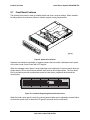
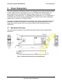
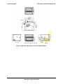
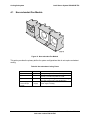
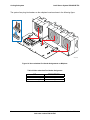
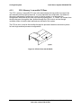
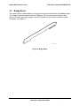
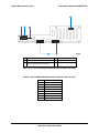
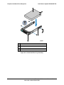
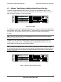
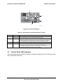
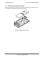
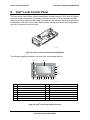
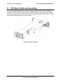
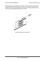
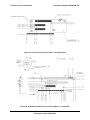
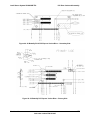
Intel® Server System SR2625UR TPS 3.2 Power Subsystem Single Power Supply Module Population In single power module configurations, server management firmware requires that the power supply module be populated in the top power module slot. The non-operating slot must have the power supply blank installed. AF000023 Figure 14. Power Supply Blank Configuring a single power supply module in the bottom location causes the server management firmware and BIOS to generate a system error during POST and the error is reported to the System Event Log (SEL). 3.3 Handle and Retention Mechanism Each power supply module includes a handle for module insertion to or removal from the module enclosure. Each module has a simple retention mechanism to hold the power module in place once it is inserted. This mechanism withstands the specified platform mechanical shock and vibration requirements. The tab on the retention mechanism is colored green to indicate it is a hot-swap touch point. The latch mechanism is designed to prevent insertion or removal of the module when the power cord is plugged in. This aids the hot-swapping procedure. 3.4 Hot-swap Support Hot-swapping a power supply module is the process of extracting and re-inserting a power supply module from an operating power system. During this process, the output voltages remain within specified limits. Up to two power supply modules may be on a single AC line. The power supply module can be hot-swapped using the following procedure: Extraction: To remove the power supply, unplug the power cord first, and then remove the power module. This can be done in standby mode or power-on mode. Insertion: Insert the module first, and then plug in the power cord. If the system is powered off, the system and the power supply will power on into standby mode or power-on mode. 21 Revision 1.2 Intel order number E46130-005