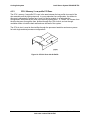
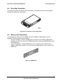
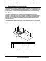
1
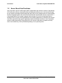
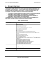
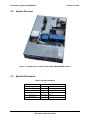
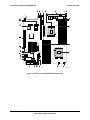
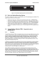
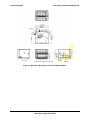
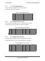
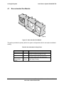
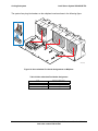
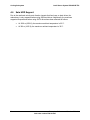
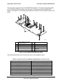
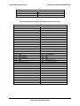
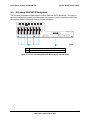
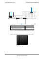
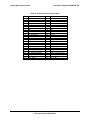
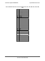
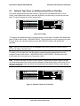
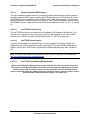
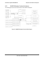
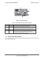
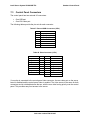
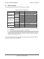
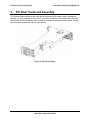
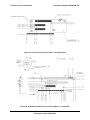
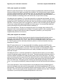
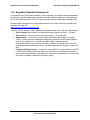
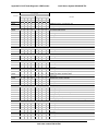
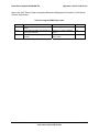
Standard Control Panel
Intel® Server System SR2625UR TPS
Power and
Sleep LED
Hard Drive
Activity LED
System
Status LED
NIC1 and NIC2
Activity LEDs
System
Identity LED
TP02112
Figure 40. Control Panel LEDs
The following table identifies each LED and describes its functionality.
Table 44. Control Panel LED Functions
LED
NIC1 / NIC2
Activity
Power / Sleep
(on standby power)
Color
Green
Green
Off
Green
System Status
(on standby power)
Amber
State
On
Blink
NIC Activity
On
Legacy power-on / ACPI S0 state
Blink 1,4
Sleep / ACPI S1 state
Off
Power-off / ACPI S4 or S5 state
On
Blink
Disk Activity
System Identification
Running / normal operation
1,2
On
Blink
Off
Description
NIC Link
Degraded
Critical or non-recoverable condition.
1,2
Off
Non-critical condition.
POST / System Stop
Green
Random blink
Provides an indicator for disk activity.
Off
Off 3
No hard disk activity
Blue
On
Identify active via command or button.
Off
Off
No Identification.
Notes:
1.
Blink rate is ~1 Hz at 50% duty cycle.
2.
The amber status takes precedence over the green status. When the amber LED is on or blinking,
the green LED is off.
3.
Off when the system is powered off (S4/S5) or in a sleep state (S1).
4.
The power LED sleep indication is maintained on standby by the chipset. If the system is powered
down without going through the BIOS, the LED state that is in effect at the time of power-off is restored when
the system is powered on until the BIOS clears it. If the system is not powered down normally, it is possible
that the Power LED is blinking while the system status LED is off. This is due to a failure or configuration
change that prevents the BIOS from running.
The current limiting resistors for the power LED, the system fault LED, and the NIC LEDs are
located on the server board.
70
Enterprise Platforms and Services Division
Intel order number E46130-005