1
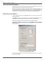
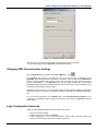
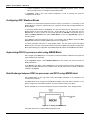
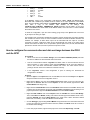
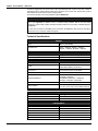
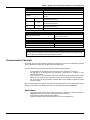
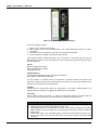
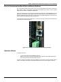
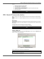
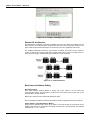
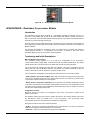
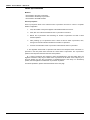
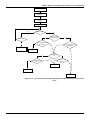
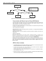
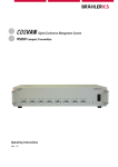
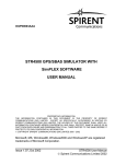
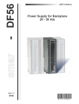
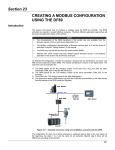
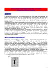
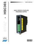
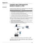
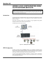
Section 18 ADDING LOGIC CONFIGURATION USING CO-PROCESSORS MODULES NOTE This section refers to the configuration between the DF51 controller and the DF65 co-processor. Therefore, this feature (adding logic) is also supported by DF62, DF63, DF73, DF75, DF79, DF81, DF89, DF95, and DF97 controllers but using the Flexible Function Block (FFB). See the Adding logic by using flexible function blocks section. Introduction As described previously, the DFI302 allows the users use several function blocks that can access input and output modules. However, for some applications, the logic configuration using function blocks is not suitable. Using DF65 (co-processor module), users can implement a logic configuration through ladder language, and interact with all modules of the DFI302 system. The figure below shows the system overview: Figure 18. 1 - DFI302 System and Co-processor DF65 Configuration The DF65 co-processor uses the LogicView software for its configuration. Remember that the DF51 (Processor) must be configured as Master, and the DF65 (co-processor) must be configured as Slave. The physical connection between both is done via DF68 when using a RS-232 port. Another option could be using the DF58 module to allow a RS-485 connection. In order to set the configuration parameters of the DF65, it is necessary to put the communication switch in the default position, if the user does not know how the DF65 was set or it is the first time you are testing this communication. 18.1 DFI302 – User’s Manual – AUG/14 - E Serial Communication Settings The DF65 has a group of 4 switches located between the communication ports. Using a small screwdriver and make sure that the lower switch is pointing to the left. The switch in this position sets the DF65 on the Modbus default communication parameters. This means that the Device ID, also called Device Address, is number 1, the baud rate is 9600 bps and the parity bit is even. These parameters can be changed later using the LogicView software, but they will only take effect when the Communication Switch is back to the Non-Default position. Physical Layer and Timeout In order to visualize the DF51 in the LogicView software it is necessary to configure some parameters in advance. Using FBTools, check the IP address of the DF51 to be configured in the LogicView. Thus, every configuration performed will be sent to DF65, this means that the DF51 will act as bypass. Remember that the DF65 must have the same baud rate as DF51 (9600 bps default). Choose Comm. Settings on the Tools menu. Select the Interface tab, and then Ethernet (Modbus/TCP). Enter the IP address of the DF51 that the LogicView will establish communication. See the figure below: Figure 18. 2 – Setting the IP address of DF51 Next, select the Time out tab. Then set the time out and the number of retries for the computer in case of bad communication. 18.2 DFI302 - Adding Logic Configuration Using Co-processor Modules Figure 18. 3 –Setting the Time out parameter Now the user can create the network ladder configuration and send it to the DF65. In case of plant startup see the LogicView manual for further details. Changing DF65 Communication Settings Open the DF65 Online box using the menu Tools Online, or click . The LogicView will connect to the DF65 as soon as the online mode is established. If the LogicView cannot detect any DF65 co-processor, it will wait in “time out” state and the DF65 Online dialog box will keep opened. This gives the user a chance to modify some parameters to correctly set the communication. If the LogicView finds that the DF65 matches the communication parameters already configured, it will add information to the Device Version, Device Release, Device Configuration Name and to the present Status. Remember that the DF65 has a communication switch indicating that the default communication parameters are active. In this case, the address is number 1, the baud rate is 9600 bps and parity is even. To see the DF51 parameters, select Default option under Communication Parameter. In this condition it is not possible to make changes in the Serial Port frame. Refer to LogicView manual for further details. Logic Configuration Download Make sure that all steps described above were performed correctly: Physical connection (cables). Location of DF51 in the subnet via FBTools. Correct configuration of the serial communication between DF65 and DF51 (DF65 DIP switches, baud rate, parity, serial communication channel, etc). 18.3 DFI302 – User’s Manual – AUG/14 - E Correct configuration of the communication between LogicView and DF65, that is., through Ethernet using the DF51 as a bridge to bypass Modbus data. In LogicView, create a new Logic Ladder configuration or load an existing one. Send the configuration to the DF65. Configuring DF51 Modbus Blocks To establish the communication between the DF51 and the co-processor, it is necessary to add Modbus blocks to control the communication, the supervision and the data exchange between the DF65 and DF51. To add these Modbus blocks in the Syscon, the user must work with two DD versions. To add Modbus blocks the user must select Dev Rev = 02 and DD Rev = 01 and insert them into the Process Cell. In order to do this, the user should right-click the FB VFB of the DFI302, which is added to Fieldbus Networks. Then select “Attach Block”, or use the “drag-and-drop” option to move the blocks. In the Syscon’s Logic Plant (whose tag is Area 1, for example), click the Area 1 and choose New Process Cell. Select the necessary Modbus blocks for the configuration. For further information about how to insert Modbus blocks, the user should consult the Adding Modbus section. The user must include a Resource block and a MBCF block (Modbus Configuration Block) before starting the configuration of the MBSM supervision block and the MBCM control block. Supervising DF65 Co-processor data using MBSM Block After configuring the MBSM block, it is necessary to select the Modbus addresses of the input and output variables to be monitored. In the LogicView program, choose Modbus Address on the toolbar, then read and write the Modbus addresses. In the Syscon Logic Plant, create a MBSM block and configure all the necessary parameters by inserting the Modbus addresses of the variables. Thus, the user will be able to monitor the Modbus variables in the Syscon. Data Exchange between DF65 co-processor and DF51 using MBCM block Add a MBCM block to the Logic Plant. Select the Modbus addresses of the variables to be controlled and monitored. The MBCM block can be configured to read Modbus variables. Then write them on the DF51. It can also be configured to read Fieldbus variables, and then should be written on the DF65. Another possibility is to connect two DF65 peer-to-peer communications. See in the figure below: Figure 18. 4 –Setting the MBCM block This figure shows how to configure MBCM parameter blocks. 18.4 DFI302 - Adding Logic Configuration Using Co-processor Modules Modbus Input variables - transmitters, discrete sensor data, etc, mapped to the Fieldbus world through a MBCM block. The user inserts the Modbus variable address on the configuration parameters of the MBCM block. Modbus Output variables - data mapped to Modbus environment as, for example, an alarm signal, an interlock, etc, can be sent to the Logic Co-processor System through the block MBCM. The user inserts the Modbus variable address on the configuration parameters of the MBCM block. Peer-to-Peer - it is possible to read a variable of a module connected to the DF65 and write its value in other module through the MBCM block. The following example describes a simple application of these function features. In order to make the explanation easier, discrete output and input modules are used, although it is possible to use the same procedure to analog variables. Example of communication between DF51 and DF65 with Ladder Logic In the example above, there are two modules: a DF20 digital ON/OFF switch input module, and a digital relay output module. Two configurations will be done to implement the communication, supervision and data exchange between DF65 and DF51. Figure 18. 5 – Communication between DF51 and DF65 with ladder logic In LogicView, begin a new configuration. Add the DF20 and DF27 modules, and a virtual module. Then insert the following simple ladder logic. Figure 18. 6 –Ladder logic example Switches 1 and 2 on module DF20 are connected to the contacts, and the outputs of these contacts are connected to two coils connected to the module DF27 outputs. Similarly, a virtual variable was assigned to a third contact. The Modbus addresses of these variables are: 18.5 DFI302 – User’s Manual – AUG/14 - E • • • • • • DF20_1 DF20_2 DF27_1 DF27_2 DF27_2 VM1 10001 10002 1 2 3 02001 In the Syscon, create a new configuration. Add Resource, MBCF, MBSM and MBCM blocks. Remember that a Modbus input variable must be inserted in an output parameter of the MBCM block. Thus, the Modbus 10001 address in LOCATOR_OUT_D1.Modbus_ADDRESS_OF_VALUE. After, make a copy of the Modbus input variable of the DF20_1. The LOCATOR_OUT_D1.Modbus_ ADDRESS_OF_VALUE parameter must be 02001. So, the input value of the MBCM block will be written in the address 02001, and in this case is a virtual variable associated to the contact. To finish the configuration, open the control strategy (Logic Part) in the Syscon and connect the IN_D1 input to the OUT_D1 output. This example uses only discrete variables and modules, however analog input and output variables and modules can also be used, as well as Fieldbus modules connected to Modbus modules and variables. For example, an alarm block output can be associated with the output of a module connected to a DF65. A PID block output can be associated with the output of an analog output module connected to the DF65. Thus, it is possible to split the plant control, so that, while the DF65 performs the discrete control, the DF51 performs the process control. How to configure the communication and data exchange between the DF65 and the DF51 In LogicView On the Tools menu choose Comm. Settings, then select Ethernet Modbus(TCP/IP) and insert the DF51 IP address in which the DF65 will communicate. Test the communication between LogicView and DF65, which is done via Ethernet and the serial connection. In case of failure, check using the FBTools if the IP of the DFI address is correct. See if the DF65 communication switches are correct. The fourth switch must be pointing to the left. Check if the cables are connected correctly. In the LogicView, create a new configuration or open an existing one. Download the configuration to the DF65. In Syscon Open the Syscon. On Project File menu choose New, and then choose Project. The Syscon will open a window to save the configuration. Save it. Right-click the Area 1 icon and choose New Process Cell. Assign a tag to this process cell. Right-click the Process Cell and choose Expand. On the new window, right-click the New Control Module and assign a tag. Right-click the Control Module and choose New Block. Select Resource and MBCF blocks, and configure them as described in this manual. Add the MBSM and MBCM blocks according to the project requirements. Right-click Fieldbus Networks and choose New Fieldbus. Right-click New Fieldbus and choose Expand. Click the Fieldbus and choose New Bridge. Then, select Smar and DFI302, making sure that the DD will support the Modbus blocks. Then, right-click FB VFD and choose Attach Block on the popup menu. Attach all blocks created before and, if necessary, create other Modbus function blocks. Choose Strategy by right-clicking Control Module. Drag the blocks to the new window that need to have two inputs set. Remember that the Resource, MBCF and MBSM blocks do not need to be included in this strategy. In the main project window, right-click the project icon and choose Export Tags. Click OK. 18.6 DFI302 - Adding Logic Configuration Using Co-processor Modules Right-click the Fieldbus Network icon and choose Comm. Settings. Check if the server ID is Smar.DFIOLESERVER.0. Click the DFI located in the main project window. Make sure that the Device ID is correct. Download the configuration. In the MBCF block, choose On Line Characterization and change the ON_ APPLY parameter to Apply. The user will be able to monitor the system through the LogicView and Syscon, simultaneously. DF65 – Co-processor Module DF65 - Co-processor module with 28 Kbytes of non-volatile memory for user configuration and a microcontroller of 15 MHz with real time clock and master of remote I/O system. DF65R - Co-processor module with 23 Kbytes of non-volatile memory for user configuration and a microcontroller of 15 MHz with real time clock and Redundant master of remote I/O system. DF65E Co-processor module with 52 Kbytes of non-volatile memory for user configuration and a microcontroller of 15 MHz with real time clock and master of remote I/O system. DF65ER - Co-processor module with 44 Kbytes of non-volatile memory for user configuration and a microcontroller of 15 MHz with real time clock and Redundant master of remote I/O system. DF65 28K 1024 1024 Configuration Memory Size Discrete Points (physical + virtual) Analog Points DF65R 23K 1024 1024 DF65E 52K 2000 1024 DF65ER 44K 2000 1024 Description The DF65 is the logical co-processor module for the DFI302 system. It is the module that runs the programmed configuration and interacts with all the other modules of the DF65 System. DF65 P1 RS-232C Modbus +5VDC RUN HOLD PGND TX RX TX P2 P3 D3/65 - Logic Coprocessor TX 7 NOT USED 1 2 3 RIO Baudrate 4 Modbus Parameters P3 Mod/RIO P2 Modbus RX P1 1Logic G 8xCoprocessor Temperature In TX 5 GND FORCE RX 1 2 3 4 RX RTS CTS T/R+ 3B T/R- 4B GND 5B T/R+ 6B T/R- 7B GND 8B FAIL R 9B Fail V 10B Fail smar Figure 18. 7 –Co-processor Module 18.7 DFI302 – User’s Manual – AUG/14 - E It must be plugged into the second slot of the rack addressed with 0 (zero). This rack number is adjusted through a rotating switch located in the electronic circuit of the rack. The first slot of rack 0 must always be reserved for the power supply module. The firmware update is done using SMAR’s software DF65Tools. NOTE The DF65 can read all I/O modules that support Module ID since the option “Use Module I/O with ID” in the LogicView is enabled. Thus, in systems having modules that do not have these features or systems that combine modules with these features it is necessary to disable flag in the LogicView. In case the connection of the DB9 port is permanent, the DB9-EXT cable must be used which allows the user to close the module front panel. Technical Specifications MEMORY Type Electrical Erasable Programmable Read Only Memory (EEPROM) Available Size DF65 – 28Kbytes, DF65R – 23Kbytes DF65E – 52Kbytes, DF65ER – 44Kbytes Software Package Operating System CONFIGURATION/OPTIMIZATION LogicView Version 6.5 or higher Windows NT, Windows 2000 and Windows XP COMMUNICATION PORTS Quantity 3 1-EIA-232-C (P1) Types 2-EIA-485 (multidrop, P2 and P3) Female DB9 to EIA-232-C (P1) Connectors Terminal blocks for EIA-485, DF66 Label See Modules and Accessories P1: 9600 bps P2 9600-115200 bps Baud Rate/Address P3 (Modbus): 9600 bps ~115200 bps P3 (RIO): 57600 bps ~230400 bps Protocol Modbus RTU (Slave) 2 a 127, Set by User(1 is default) Slave Address 2 to 121, set by user (1 is the default address) Maximum number of DF65 per network 31 Provided by the IMB Bus Total Maximum Dissipation Power Indicator Output Type Limits Maximum Initial Contact Resistance Status Indication Logic Indicator Over Load Protection: Operation Time 18.8 INTERNAL POWER 5 Vdc @ 320 mA 1.6 W Green LED +5 Vdc FAILURE RELAY Solid state relay, normally close (NC) 6 W, 30 Vdc Max, 200 mA Max. <13Ω Red LED- Fail LED ON (relay closed) Should be provided externally 5 ms maximum DFI302 - Adding Logic Configuration Using Co-processor Modules RUN HOLD FORCE Rx Tx Rx Tx Rx Tx FAIL P1 P2 P3 Dimensions (W x H x D) Weight One Wire Two Wires OTHER LEDS Green LED- indicates program running Yellow LED- indicates program in hold mode Red LED- indicates all inputs and/or outputs are in the force mode. Displays Modbus Communication (EIA-232) RX (Yellow) TX(Green) Displays Modbus Communication (EIA-485) RX (Yellow) TX(Green) Displays Modbus Communication (EIA-485) RX (Yellow) TX(Green) Red LED- Indication of failure DIMENSIONS AND WEIGHT 39.9 x 137.0 x 141.5 mm (1.57 x 5.39 x 5.57 in) 0.286 kg CABLES 2 14 AWG (2 mm ) 2 20 AWG (0.5 mm ) NOTES To increase service of life of the relays and to protect the modules from reverse voltage damages, externally connect a clamping diode in parallel with each inductive DC load or externally connect an RC snubber circuit in parallel with each inductive AC load. Communication Channels The DF65 has three communication channels that supply the user with 3 independent channels (ports) identified as P1 (EIA-232), P2 (EIA-485) and P3 (EIA-485). The three channels may be used at the same time with the following features: o o o o P1 (EIA-232) is for programming and monitoring, point-to-point short connections. P2 (EIA-485) is for programming and monitoring, point-to-point or multidrop in long industrial connections. P3 can mimic P2 or act as a Master channel for a DF66 connection DF66 interface module (DF66). A rotary switch on the co-processor module card can set the P3 channel behavior. Any of the ports can be connected to the Smar ENET-700 or ENET-710 (Ethernet-Serial) converter module. Due to communication requirements, the DF65 has a Modbus ID that is unique and a different baud rates for P1 and P2/P3. The Modbus baud rates are set through the software LogicView. Restrictions: o o o Only one channel can be used at the same time to monitor the network through the LogicView. Other channels will be locked after the first one begins. All channels are referred with the same address. Channels P2 and P3 shares the same baud rate. P1 has a dedicated one. 18.9 DFI302 – User’s Manual – AUG/14 - E Figure 18. 8 – DF65 Communication Channels In the previous figure is shown: 1- DF65 P1 port. It is an EIA-232 channel; 2- SSIO channel used by the redundant DF65. See “DF65 Redundant Module” for further information. 3- DIP switches used to change the co-processor communication parameters. 4- Ports P2 and P3 of the DF65. These are EIA-485 channels. There are three serial communication ports on the co-processor: one EIA-232 port (P1) and two EIA-485 ports (P2 and P3). The user should set to any of these ports: baud rate, parity and other specific parameters. Port P1 Baud rate (9600 bps) for DF65. Baud rate (9600 bps) for DF65R. Parity (Odd or Even) RTS/CTS Timeout CTS: Signal that indicates the device is ready for transmission. RTS: Signal to request data transmission The PC requests a connection with the co-processor. The DF65 receives this request and processes it. Next, the DF65 sends the RTS signal and it waits for the CTS signal during the time interval set on the RTS/CTS Timeout parameter. OFF Duty Available time for communication when the co-processor is not running a ladder diagram. The biggest value set for Off Duty, the biggest time available for communication. Time Delay The PC sends a frame to the DF65, i.e., makes a communication request. The DF65 waits the amount of time set on Time Delay to process the frame request and send the answer. NOTES For better performance of the system, it is recommended: • Off duty must be set as 20% of the Ladder execution cycle. • Time Delay depends on the Workstation’s processor. If the processor is higher than a Pentium MMX 233 MHz, set the Time Delay to 5 ms. Otherwise the Time Delay must be set with the default value. • When the DIP switch 4 is in the default position or if the value set for Off duty is equal to zero, then the real value set for Off duty will be 20% of the cycle (modules scan plus Ladder execution). 18.10 DFI302 - Adding Logic Configuration Using Co-processor Modules Device Communication Baud Rate and Device Address The co-processor module has a key where the user may select default communication parameters (DCP, Switch 4 ON) or programmed communication parameters (PCP, Switch 4 OFF). Default parameters are address 1 and baud rate 9600 bits/s. In the PCP position the user can select a new address and/or baud rate, using LogicView. The new adjustment of parameters will be accepted only after the key being moved to the PCP position. In the PCP position the user is also able to change the communication parameters. In this case they will be accepted immediately after they have been sent. The default values apply to three channels: P1, P2 and P3. The user can set the DIP switches using a key as shown in the next the figure: Figure 18. 9 – Setting the Communication Parameters of the DF65 Operation Modes The DF65 may act as: o o A co-processor with three Modbus/RTU channels Master co-processor in a system with DF66, where 2 channels work as Modbus/RTU and the remaining one (P3) as remote master channel. In order to change the operation mode of the DF65 the user needs to change the Rotary Switch position. This rotary key is located underneath the DF65 module. See the next figure to locate it. 18.11 DFI302 – User’s Manual – AUG/14 - E Figure 18. 10 – Locating the DF65 Rotary Switch Detail: The Rotary Switch DF65 with Three Modbus RTU Channels When the DF65 is used as a regular co-processor, it means that no DF66 module is being used. Also, either P3 as P1 and P2 may act are available as Modbus/RTU channels. Note that none of them can act as a Modbus master. P1, P2 and P3 are independent Modbus/RTU slave channels. They can be used at the same time. P1 is recommended for point-to-point connections whereas P2 and P3 may be used in two different networks (master and slave) to increase accessibility of the co-processor through two computers (masters) or in a redundant architecture where the user can alternate between the channels in a failure situation. Settings: The rotary key must be in the position 8; One Modbus ID set for P1, P2 and P3 (set on LogicView); The P1, P2 and P3 baud rates are set on LogicView. DF65 Master in a DF66 System The DF65 can be also a master in a DF66 system. This means that the DF65 acts as the main processing unit acquiring data from the DF66 modules in its own IMB and also from any DF66 connected to it. In this case P3 is completely dedicated to DF66 communication data. P1 and P2 are slave Modbus/RTU independent channels. P1 is used for point-to-point applications whereas P2 may be used in a multidrop network. Settings: The rotary Switch must be in the position 0; One ID Modbus for P1 and P2 set on LogicView; P1 and P2 baud rates are set on LogicView; P3, the remote channel, has its own dedicated baud rate set through the frontal DIP switch. Factory Init The user can carry out a procedure to make the DF65 to assume its factory configuration. This procedure is called factory init. 18.12 DFI302 - Adding Logic Configuration Using Co-processor Modules To do it: 1. 2. 3. 4. 5. 6. Remove the DF65 from the power supply; Put the Rotary Switch on the position 7; Put the DIP Switch 4 in the default position; Connect the DF65 to the power supply and wait until the HOLD LED starts to blink; Remove the DF65 from the power supply; Set the rotary switch. NOTE After the factory init procedure the user must set the rotary swtich when a new download is done. DF66 – Remote I/O Communication Interface DF66 – 28 kbytes of non-volatile configuration memory and a microcontroller of 15 MHz with DF66 (Slave) DF66E – 52 kbytes of non-volatile configuration memory and a microcontroller of 15 MHz with DF66 (Slave) Description DF66 modules are located close to the field devices and allow a flexible architecture to the system. DF66 units use the same I/O modules designed for the regular DF65 system combined with the DF66 module. The DF66 module must be used together with DF65 and DF65R. The DF66E module must be used together with DF65E and DF65ER. NOTE The DF65 firmware update is done by the SMAR DF65Tools software. Adding a DF66 unit To add a DF66 system, click the Go to I/O module page, and then click the Add/Delete DF66 system. As shown in the following figure. Figure 18. 11 – Adding a remote system Choose a DF66 system, and click the corresponding button. ATTENTION The address and baud rate of the DF66 interface module must be set. Interface and Power Supply modules for DF66 are automatically set. 18.13 DFI302 – User’s Manual – AUG/14 - E Figure 18. 12 – Adding or removing a remote system Remote I/O Architecture The DF66 System is basically composed of a Master Unit and up to 6 Slave Units. Master Unit and Slave Units are connected through a multidrop cable that can reach a total length of 4000 ft. The proper cable length and baud rate depend on the level of noise in the application environment. The available Rack/Slots will limit the total number of modules per system and the maximum number of Discrete and Analog Points that the DF65 will be able to work. Each DF66 needs, at least, one power supply. A DF65/ DF66 system structure is shown as follows: Figure 18. 13 – DF66 Architecture Baud rate and Address Setting Baud Rate Settings Each DF66 Interface Module (Master or Slave) has a DIP switch to set the baud rate (communication speed). The DIP switch is located in the frontal panel of the module and can be accessed with a small screwdriver. Make sure to disconnect the module while setting the switch. Also note that both the Master and Slave I/O interface must be configured with the same baud rate. Setting Address of the DF66 Interface Module There is also a dedicated rotary switch at the bottom of the slave module to set the slave device address. Each remote unit connected to the master unit must have a unique address. The available addresses are: 1, 2, 3, 4, 5 and 6. 18.14 DFI302 - Adding Logic Configuration Using Co-processor Modules Figure 18. 14 – Setting Address of the DF66 Interface Module DF65R/DF65ER – Redundant Co-processor Module Introduction The redundancy with the DF65 is based on a hot-standby mechanism. Therefore, just one coprocessor runs the ladder logic as well as the communication with HMI at a specific moment. The active co-processor scans the DF66 module while the passive co-processor monitors the status of the active co-processor through another port. However, there is communication between the co-processors in order to keep the synchronization of the configuration and also provide fresh dynamic data to the passive co-processor. For example: the Modbus variables. The algorithm responsible for choosing the active co-processor tries to minimize the number of control switches; therefore, if a co-processor runs as active, it remains in this state, unless something happens to put this co-processor in bad conditions. Terminology and Initial Descriptions Main and Backup Co-processors The redundancy status depends on a lot of items as: configuration of the co-processor, communication status through SSIO, communications with the DF66 modules DF66. This status defines whether the co-processor will run the ladder logic as well as scanning the RIOs. The co-processor can assume two roles: active and passive. The active co-processor runs the ladder logic and scans the Modbus variables. The passive co-processor periodically checks the active co-processor in order to check if it is necessary to take control. The co-processor’s configuration is set through the rotary switch in the co-processor module: - Rotary Switch in the position 0 (Main): When both co-processors are powered-up at the same time and, the algorithm checks the rotary switch position (of both co-processors) to choose which co-processor is active and which one is the passive. - Rotary Switch in the position 9 (Backup): The co-processor set as backup transfers the control to the other co-processor its current status is both passive or both active. This configuration is used only when the co-processors are simultaneously powered and when both are passive or active at the same time before the last power-down. Configuration Transfer During the power up procedure, the configuration of the active co-processor is passed to the passive co-processor. This transfer is always done from active to passive and never in the contrary direction and it uses the Synchronous Serial I/O (SSIO) Port of the Co-processor. This synchronous serial communication channel is used exclusively to transfer the configuration. During this process two new terms need to be defined: - Sender: This is the co-processor responsible for the communication. The sender co-processor handles the configuration transfer between the co-processors. - Addresser: This is the co-processor that receives the configuration. 18.15 DFI302 – User’s Manual – AUG/14 - E Configuration synchronism between the Co-processors This is accomplished in two main phases: Phase 1- Configuration Transfer When a sequential power up procedure takes place, the first co-processor powered-up becomes the active co-processor and it transfers the configuration to the other one. Phase 2- Updating Transfer After the Configuration Transfer Phase, it is necessary to transfer only the dynamic variables and the settings that can be done without configuration download. ATTENTION This refers to Modbus variables, configuration of switches in the co-processor module and communication settings. Rules to Select the Sender and Addresser When the co-processor detects the presence of other co-processor through the SSIO, they exchange some status information to decide which will be the sender of configuration. Three main cases can occur: # 0 1 2 RULE If configuration name, date and time in both co-processors are the same and Good-Config, the rules to select the active co-processor will be applied, and the active co-processor will be also the Sender. If configurations mismatch and a sequential power up happened and the first co-processor has a Good-Config, then the first co-processor to power up will be the sender. All other cases (configuration mismatch and simultaneous power up OR one or both with bad-config): co-processors do not enter transfer status. SCENARIO Power cycle of configured system Replace of co-processor module First power up of system after a firmware download or abnormal cases. The SSIO port Diagram Figure 18. 15 – The SSIO channel In order to transfer the configuration from the active co-processor to the passive it is necessary to use a special cable to connect the two co-processors. The cable part number is DF76. This port cable is a 4 wires-cable that implements a full-duplex channel whose baud rate is 1.875 Mbps. 18.16 DFI302 - Adding Logic Configuration Using Co-processor Modules Architecture Consider the figure below: Figure 18. 16 – Redundant Architecture Example The above architecture shows an illustrative example of the hardware used in the DF65R redundancy. - Two Ethernet paths; - Two DF50 modules allow complete redundancy; - Two co-processors with main and backup roles; - A DF66 module scans the Modbus variables; - The DF76 cable connects the two co-processors. NOTE The I/O modules are only included in the racks where the DF66 module is present. 18.17 DFI302 – User’s Manual – AUG/14 - E Power up Procedures Breakers - One breaker to the main co-processor. - One breaker to the backup co-processor. - One breaker to the DF66 modules. Power up sequence Power up sequence refers to the order that each co-processor is turned on. There is a specific breaker configuration. 1. First, the breaker of the power supplies of the DF66 modules is turned on. 2. Next, each one of the two breakers of each co-processor is turned on. 3. Before the co-processors start searching for another co-processor the state of both becomes passive. 4. After powering up a co-processor and if it does not find an active co-processor, then, during a two seconds interval it will search for another co-processor. 5. If it does not find another active co-processor it becomes the active co-processor. I - The algorithm checks which co-processor was active in the last power down. The active coprocessor in the last power down becomes the current active co-processor. The co-processor passive in the last power down becomes the current passive. II - If both o-processors were passive or active simultaneously in the last power down, the algorithm checks the rotary keys to define which co-processor will be active. If the rotary key is in the main position (0), then the co-processor is considered active. If the rotary is in the backup position, then the algorithm considers this co-processor as passive. For further explanation, please check the flowchart in the next page. 18.18 DFI302 - Adding Logic Configuration Using Co-processor Modules Turn Rio breaker on Turn CPU1 and CPU2 breakers on CPU1 and CPU2 become passive Start counter CPU2 found CPU1? No Yes No CPU1was active in last power down? No Counter>=2sec No Yes Yes CPU2 was passive in last power down? CPU2 was passive in last Yes power down? No Check conditions CPU2 gets active No No Is CPU2 the Back up CPU? Is CPU1 the main CPU? Yes No Signalize error Yes Is CPU2 the Back up CPU? Yes Yes CPU2 gets active CPU1 gets active Figure 18. 17 – Flow chart representing the algorithm that decides which co-processor will be active 18.19 DFI302 – User’s Manual – AUG/14 - E Check conditions No CPU gets active Is CPU configured? No Yes Nrio_BK>Nrio_main Main CPU gets active Nrio_BK= number of RIO modules seen by the backup CPU Nrio_main= number of RIO modules seen by the main CPU Yes Backup CPU gets active Figure 18. 18 – Flow chart representing the check conditions procedure Communication with Remote Input and Output (RIO) Modules The DF66 modules are scanned only if the name of the configuration and date are the same in the main co-processor and DF66. The passive co-processor sends polling commands to check periodically whether it is necessary to assume the control. As seen in the system architecture figure, the DF66 modules are connected to the system through two different and redundant channels. There are two ports to be considered: DF66 Active Port: Port being scanned by the active co-processor, i.e., through this port the Modbus variables are read and written. DF66 Passive Port: In this port the passive co-processor checks the conditions of the active and passive ports. Switch Over Procedure During the normal functioning of the system, there’s a switching procedure. It is based on the number of the DF66 that the active co-processor can communicate with (NRIO active) and the number of DF66s that the passive co-processor can communicate with (NRIO passive). If NRIO active is shorter than NRIO passive, then there is a switching over procedure that makes the current active co-processor the passive co-processor and the old passive co-processor the current active co-processor. This procedure ensures that the system reads the biggest amount of I/O Modbus variables. LEDS for Status Indication A solid RUN LED (green, ON or OFF) indicates if the co-processor is in active state while a blink RUN LED indicates that the co-processor is in passive state. A solid HOLD LED (yellow, ON or OFF) indicates if the co-processor has been configured properly, while a blink HOLD LED indicates that it was not. A solid FORCE LED (red, ON or OFF) indicates if the co-processor is in FORCE-IN, FORCEOUT or SAFE-OUT mode, or not. FORCE LED indicator on passive co-processor is blinking. It indicates that the hardware settings are not correct (rotary switch, BR for DF66 or firmware version). 18.20