1
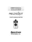
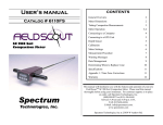
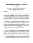
User’s manual
Catalog # 6435FS,6440FS
TDR 100/200
Soil Moisture Meter
Spectrum
Technologies, Inc.
CONTENTS
General Overview
3
Specifications
4
Identifying the Correct Com Port
5
Connecting to a Computer/
Changing Batteries
6
Main Toolbar
7
Meter Operation
8
Meter Settings
10
Volumetric Water Content Measurements
12
Relative Water Content
14
Appendix 1: Time Zone Corrections
15
Appendix 2: Soil-Specific Calibration
16
Warranty
18
This manual will familiarize you with the features and operation of
your new Field ScoutTM TDR Soil Moisture Meter. Please read this
manual thoroughly before using your instrument. For customer
support, or to place an order, call Spectrum Technologies, Inc. at
(800)248-8873 or (815) 436-4440
between 7:30 am and 5:30 p.m. CST
FAX (815)436-4460
e-mail: [email protected].
www.specmeters.com
Spectrum Technologies, Inc
12360 S. Industrial Dr. East
Plainfield, IL 60585
2
General overview
Thank you for purchasing the Field ScoutTM TDR Soil
Moisture Meter. This manual describes the features
and operation of the meter.
Soil moisture is a critical and, potentially highly variable component of the soil environment. Time-domain
reflectometry is a proven technology for quickly and
accurately determining volumetric water content
(VWC) in soil.
The Field Scout probe allows the user to easily and
rapidly take many measurements. The user can quickly
transition between taking VWC readings in standard
and high-clay mode. Through the software, the user
can program relative water content modes for multiple
sites.
3
Specifications
Measurement
Units
Percent volumetric water content
Resolution
0.1%
Accuracy
±3.0% volumetric water content
with electrical conductivity < 2 dS m –1
Range
0% to saturation (Saturation is typically
around 50% volumetric water.)
Power
4 AAA alkaline batteries
Approximately 12 month life
Display
16 character, 2 line LCD
Weight
Model 100 1.5 lbs. (0.68 kg)
Model 200 3.0 lbs. (1.36 kg)
Probe Head
Dimensions
3.1” x 3” x 1”
(7.8cm x 7.5cm x 2.5cm)
Rod Dimensions
Length : 3” (7.6cm), 4.7” (12cm) or
7.9” (20cm)
Diameter: 0.2” (0.5cm)
Spacing: 1.3” (3.3cm)
The meter’s LCD screen will display the data in one of
three modes (see Meter Operation p. 9):
1. Volumetric water content - in Standard or High Clay
mode
2. Relative water content - up to 2 RWC modes can be
established
3. Measurement period - in microseconds
4
Identifying the
Correct Com Port
The
computer
Communications Port
to which the PC-3.5
serial
cable
is
connected can be
identified by using a
paper clip.
1. Disconnect the serial
cable from the meter.
2. To bring up the Port Selection screen, click on the
Com Port Button, select the com port to be tested and
click the Port Test button. Click the Test Port Now
button. If the message “Connection OK” is displayed,
another device (such as a modem) is probably connected
to that port. If the message “No Connection” is displayed,
this port may be the one connected to your serial cable and
you can proceed to the next step.
3. Place a paperclip on the end of the serial pin so that it
touches both the tip of the pin and the metal area between
the two black rings. Again click on the Test Port Now
button. If the message “Connection OK” now appears,
this is the com port connected to your serial cable.
paper clip
or wire
NOTE: The meter does not short-circuit the serial pin.
Therefore, when the Test Port Now button is clicked
while the meter is connected, the “No Connection”
message will be displayed.
5
Connecting to a
Computer/Changing
the Batteries
The data port is accessed by removing the face plate of the
digital display. It is through this port that the meter is
connected to a PC.
Connecting to a PC
The TDR meter software comes with a gray PC interface
cable. This cable connects to the 9-pin serial port of your
computer and to the meter’s computer port. The meter’s
configuration can be modified by clicking on the Meter
Settings button (see Meter Settings, p. 10). The Com
Port, Meter Type, and Clear Meter Settings buttons are
explained in the Main Toolbar section (p. 7).
Changing the batteries
The battery compartment is accessed by removing the meter’s face plate.
6
Main Toolbar
Com Port
The gray software cable connects
the meter to the computer data
port. Select the Com Port that is
assigned to the computer data
port. See Identifying the Correct
Com Port (p. 5) for instructions
on how to determine which port
to select.
Meter Type
Select the TDR option from the list
of available Field Scout meters.
Meter Settings
Click this button to configure the
meter and data logger. Refer to
“Meter Settings” (p. 10) for more
details.
Download and Clear Memory
These functions are not active with models 100 and 200.
7
Meter Operation
ON
The ON switch turns the meter on and
off. When the meter is turned on, it
will display the battery status for 3 seconds. The screen will then display the
Battery at 85%
Firmware V5.0
Sample meter power-up
and data screens
Stndrd VWC%=27.1
PL=M N008 A=26.5
Period = 0950 uS
N015
most recently used MODE screen (Volumetric or Relative
water content or measurement period).
The data screens for the Water Content Modes are explained on pages 12 and 14. The Period mode is used for
doing soil-specific calibrations and is explained on page
16.
READ
Delete
Clr Avg
8
Press the READ button to read the probe
and update the screen values. The data
point can be cleared from memory with
the DELETE/CLR AVG button (below).
When the DELETE/CLR AVG button is pressed and immediately released, the last data point will be removed from the running average.
Pressing and holding this button will
reset the running average.
Meter Operation (cont.)
MODE
Pressing the MODE button allows the
user to determine the type of measurement that will be taken or select the
length of rods connected to the probe.
Data Measurement Modes
Available measurement options are volumetric water
content (VWC) using the standard or high clay mode
(see p. 12), up to two relative water content modes (see
p. 14), or measurement period (in microseconds).
Relative water content options will only appear if they
are configured in the software (see Meter Settings, p.
10). The period measurement is available for users interested in performing soil-specific calibrations (see
Appendix 2).
Changing Rod Length
ROD=MED (4.7in)
HIT DEL To Chnge
Rod Length Options Screen
In order to get accurate volumetric or relative water
content (VWC or RWC) readings, the rod length setting must be correct. In the VWC modes, the currently
selected rod length appears in the lower left corner of
the LCD screen. The options are Short (3.0”), Medium
(4.7”), and Long (7.9”) rods. Press the MODE button
until the LCD displays the rod length options screen.
Pressing the DELETE/CLR AVG button will allow
you to toggle between the three choices.
9
Meter Settings
The Meter Settings screen in the Field Scout TDR software is used to configure the meter and data logger for
your specific application. The fields are described below.
Meter Name: The name given the meter will be the
title on the first line of the downloaded text file.
Units: When operating the meter in Relative Water
Content mode, the LCD can display the rod length options in English or metric units. The meter will calculate and display the water deficit (see Relative Water
Content p. 14) in the same unit system.
10
Meter Settings (cont.)
Relative Water Content Set Points: Up to 2 Relative
Water Content (see p. 14) modes can be programmed
into the meter by entering the wet and dry set points
into the appropriate boxes. From the dropdown menus
near the bottom of the screen, select which VWC calibration (Standard or High Clay) should be used for
each RWC mode. Each of these modes can be given a
descriptive name of 5 characters. These names can be
used to identify a certain field or soil type.
Finally, for an RWC mode to be available, it must be
enabled by checking the Enable Display box. If this
box is not checked, that RWC mode will not appear on
the LCD during meter operation.
11
Volumetric Water
Content
Measurements
The volumetric water content (VWC) is the ratio of the
volume of water in a given volume of soil to the total soil
volume. At saturation, the volumetric water content
(expressed as a percentage) will equal the percent pore
space of the soil.
The underlying principal of TDR involves measuring the
travel time of an electromagnetic wave along a
waveguide. The speed of the wave in soil is dependent on
the bulk dielectric permittivity (ε) of the soil matrix. The
fact that water (ε = 80) has a much greater dielectric constant than air (ε = 1) or soil solids (ε = 3-7) is exploited to
determine the VWC of the soil. The VWC measured by
TDR is an average over the length of the waveguide.
Electronics in the TDR 300 generate and sense the return
of a high energy signal that travels down and back,
through the soil, along the waveguide composed of the
two replaceable, stainless steel rods. The sampling volume is an elliptical cylinder that extends approximately 3
cm out from the rods. The high frequency signal information is then converted to volumetric water content. However, high amounts of clay and high electrical conductivity
(EC>2 dS/m) will attenuate the high-frequency signal and
affect the reading displayed by the meter. Very high organic matter content will similarly affect the VWC reading.
When taking a measurement, it is important that the rods
be fully inserted into the soil. If not, part of the sampling
volume will be composed of air and the reading will be
12
inaccurately low. For the same reason, the probe should
be inserted with a steady, downward pressure. If the rods
are wiggled into the soil, air pockets can be created adjacent to the rods that will result in low readings. The probe
should not be struck with a hammer or other blunt instrument as this can cause damage to the internal electronics.
Also, care should be taken to ensure the rods are inserted
as parallel to one another as possible. This will not have a
large affect on the reading but will decrease the chances
the rods will be bent or broken. Likewise, it is best to
avoid areas with rocks or other material that can cause the
rods to deflect or bend.
Stndrd VWC%=25.5
PL=L N=06 A= 23.4
The TDR meter can be set to one of two VWC modes,
Standard or High Clay. The Standard mode will be appropriate for most mineral soils. The High Clay mode will be
more accurate for soils with higher clay contents (>27%).
In VWC mode, the top line of the display shows the VWC
mode and the water content. The bottom line has the following information:
PL:
N:
A:
Probe Length (Short, Medium, or Long rods)
Number of readings included in the Average
Average of all readings taken since meter was
turned on or DELETE/CLR AVG button was
pressed
13
Relative water
Content Mode
RWC=25.5 D=3.17in
A=23.4 N=06 Asnte
In addition to displaying volumetric water content
(VWC), the meter can also display the relative water content
(RWC) and Water Deficit (see MODE button, p. 9). RWC is
an index value calculated with respect to upper (wet) and
lower (dry) VWC set points. The set points are configured
with the software (refer to Meter Settings, p. 10). An RWC of
0 indicates the soil is at the dry set point while an RWC of
100 indicates the soil has reached the wet set point. (Example:
Assume the dry set point is VWC=25% and the wet set point
is VWC=40%. If the meter measured a VWC of 35%, this
would translate to a RWC of 67 because 35% is 2/3 between
25% and 40%.) If the soil’s volumetric water content is outside the range of the set points, it is possible to get a negative
RWC or an RWC greater than 100.
If the volumetric water contents for field capacity and
permanent wilting point are the wet and dry set points respectively, the RWC value will be equivalent to Plant Available
Water (PAW). A general rule of thumb is to recommend irrigation when the soil has reached 50% of the PAW.
Also included on the first line is the Water Deficit.
The Water Deficit is the amount of rain or irrigation water
necessary to raise the soil water content to the wet set point.
This calculation applies to a soil depth equal to the probe rod
length. The water deficit can be extrapolated further into the
profile if the porosity and water-holding characteristics are
similar to the volume of soil sampled by the probe.
The second line of the LCD gives the Average (A) of
all readings taken, the Number (N) of readings taken and the
5-symbol name given to this soil type in the Meter Settings
screen (see p. 10).
14
Appendix 1
Time zone corrections
Time Zone
Correction
City
0
Dublin, Lisbon, London
3
Rio de Janeiro, Montevideo
4
Asuncion
5
7
Atlanta, Indianapolis, New York, Ottawa, Bogota,
Montreal, Toronto
Guatemala City, Houston, New Orleans, Chicago,
Mexico City, Winnipeg
Phoenix, Denver, Edmonton
8
San Francisco, Los Angeles, Vancouver
9
Anchorage
10
Honolulu
11
Wellington
13
Adelaide, Melbourne, Sydney
14
Vladivostok, Brisbane
15
Seoul, Tokyo
16
Beijing, Hong Kong, Manila, Singapore, Taipei
17
Hanoi, Jakarta, Vientiane
18
Calcutta, New Delhi
19
Kabul, Islamabad
20
Tehran, Abu Dhabi, Dubai
21
Moscow, Nairobi, Kampala, Riyadh
22
Ankara, Athens, Helsinki, Istanbul, Cairo,
Johannesburg, Harare
Amsterdam, Barcelona, Berlin, Geneva, Paris,
Prague, Rome, Brussels, Madrid, Stockholm,
Warsaw, Lagos
6
23
15
Appendix 2
Soil-Specific
Calibration
For maximum accuracy, you Period = 0950 uS
may choose to perform a N015
soil-specific calibration
rather than use either of the internal (Standard or High
Clay) soil calibrations coded into the TDR meter’s firmware. In these cases, an independent soil moisture content
measurement is required. A relation can then be developed that relates the meter’s period reading (see MODE
button, p. 9) to actual volumetric water content (VWC).
This is most easily accomplished by doing a regression of
one set of data against another.
VWC data can be obtained with a device such as a neutron
probe, by measuring the weight of a saturated soil column
of known volume as it is gradually dried, or by gradually
wetting a known volume soil with the addition of known
increments of water. In most cases, however, the calibration will be done with gravimetric sampling. This procedure is briefly described below.
In the field, establish a number of sites to sample. Each
site should be wetted to a different soil moisture content
by adding varying amounts of water. At each site a Field
Scout TDR reading is taken followed by the extraction of
a known volume of soil. Ideally, this would be an undisturbed soil core. The wet weight of this soil must be determined. If the soil cannot be weighed immediately, it
should be stored in a plastic bag to reduce evaporation.
The soil is then oven-dried (105o C for 48 hours is a common requirement) and weighed again. The volumetric
water content is calculated as follows:
16
Appendix 2
Soil-Specific
Calibration
VWC = 100*(Mwet - Mdry)/(ρw*Vtot)
Where:
Mwet, Mdry =
Vtot =
ρw =
mass (g) of wet and dry soil respectively
total soil volume (ml)
density of water (1g/ml)
An alternate, but equivalent, calculation can be obtained
from the gravimetric water content and soil bulk density.
VWC =
GWC *(ρb/ρw)
Where GWC is the gravimetric water content and ρb is the
bulk density:
GWC =
ρb =
100*(Mwet - Mdry)/Mdry
Mdry/Vtot
The final step is to plot the calculated the measured period
values with the readings obtained from Field Scout TDR
meter. Regression analysis can then be performed on this
data to develop an equation to convert from period to
VWC.
17
Warranty
The Field ScoutTM TDR Soil Moisture Meter is warranted
to be free from defects in materials and workmanship for
a period of 1 year from the date of original purchase.
During the warranty period, Spectrum will, at its option,
either repair or replace products that prove to be defective.
This warranty is void if the product has been damaged by
customer error or negligence, or if there has been an
unauthorized modification.
Returning Products to Spectrum
Before returning a failed unit, you must obtain a Returned
Goods Authorization (RGA) number from Spectrum. You
must ship the product(s), properly packaged against
further damage, back to Spectrum (at your expense) with
the RGA number marked clearly on the outside of the
package. Spectrum is not responsible for any package that
is returned without a valid RGA number or for the loss of
the package by any shipping company.
18
19
Warranty
The Field ScoutTM TDR Soil Moisture Meter is warranted
to be free from defects in materials and workmanship for
a period of 1 year from the date of original purchase.
During the warranty period, Spectrum will, at its option,
either repair or replace products that prove to be defective.
This warranty is void if the product has been damaged by
customer error or negligence, or if there has been an
unauthorized modification.
Returning Products to Spectrum
Before returning a failed unit, you must obtain a Returned
Goods Authorization (RGA) number from Spectrum. You
must ship the product(s), properly packaged against
further damage, back to Spectrum (at your expense) with
the RGA number marked clearly on the outside of the
package. Spectrum is not responsible for any package that
is returned without a valid RGA number or for the loss of
the package by any shipping company.
Spectrum
Technologies, Inc.
12360 S. Industrial Dr. East
Plainfield, IL 60585
(800) 248-8873 or (815) 436-4440
FAX: (815) 436-4460
E-Mail: [email protected]
www.specmeters.com