1
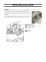
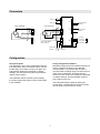
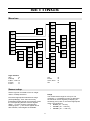
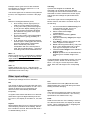
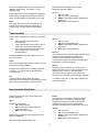
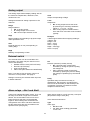
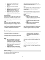
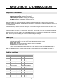
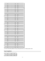
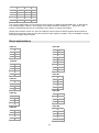
USER MANUAL 14.2.2013 V2.3 STRAIN GAUGE TRANSMITTER 6841 Nokeval 1 INTRODUCTION 6841 is a DIN rail mounted strain gauge / weighing transmitter. It is equipped with a small display and push buttons to allow configuration without a separate programming device. There are also two alarm relays, analog output, and RS-485 serial output with Nokeval SCL and Modbus protocols. The sensor can be connected using 6-wire measurement to eliminate wire resistance effect. Sensor excitation is about 10 volts DC. The device can be calibrated or taught in up to six points. SPECIFICATIONS Serial output Input Protocols Excitation: 10 V ±10% 150 mA 2.5 … 11 VDC 100 ohm 78 ohm Baud rates Bit configuration -40…+40 mV and 40…+100 mV >10 Mohm <0.02% <0.01 mV <10 ppm/°C <100 ppm/°C about 4 Hz (10 and 14 Hz also available but with less accuracy) Alarm relays mA output: Range Accuracy 25°C Overrange Max load 0-20 mA or less (e.g. 4-20) ±0.008 mA 0…21 mA typ 1000 ohms General V output: Range Accuracy 25°C Overrange 0-10 V or less ±0.005 V 0…10.6 V typ Supply voltage From transmitter Externally Max wire resistance Max load Measurement: Ranges Input impedance Inlinearity Zero error Zero drift Gain drift Update rate Response time Maximum load Nokeval SCL or Modbus RTU or ASCII-CRLF auto transmission 1200…57600 bit/s SCL/ASCII: 8N1 Modbus: 8E1 Max 100 ms 2 A / 250 VAC resistive External switch Threshold level Pullup Functions Analog output Isolation Operating temp Humidity Weight Connectors 2 about 2.5 V 5 V / 1 kohm Min/Max reset Tare Hold Alarm reset Input is isolated from outputs. Serial and analog outputs sharing common (). Power supply isolated. 85-260 VAC or 24 VDC 0..60 °C 0..95 %RH non-cond. 250 g 2 2.5 mm , detachable INSTALLATION Jumpers The case has to be opened to access the jumpers. Jumper locations and positions are represented in the picture. Factory settings are shown bold. JP1 selects between external switch input or passive 2-wire analog output on connector B1. JP1 6841 can also measure a half-bridge. In this case two 1 kohm 0.1% precision resistors have to be added on the circuit board and JP3 has to be closed. Connector B1 is an external switch input Connector B1 is a passive mA output (B1+, B2-) JP1 JP3 JP3 3 Full bridge Half bridge Connectors Alarm 1 Alarm 2 1 2 3 4 G A 3 2 4 1 6-wire connection 4-wire connection 4 +10V +10V 1 2 0V 3 + sense H - sense 0V 4 + input - input Supply voltage 24 VDC + input 1 2 - input F 3 4 2 3 2 H 1 1 4 2 3 F 4 Serial output RS-485 D1 D0 A B 3 Supply voltage 230 VAC 4 3 Strain gage sensors Max. 4 x 350 A 1 B 2 1 V output Common mA output External switch Common Configuration Using front panel The transmitter can be fully configurated using the front panel keys, but the numerical values can’t be fed precisely, since there are only four digits. The configuration settings are explained in chapter Settings, and using the front panel is described in chapter User interface. Using configuration software MekuWin program (free from Nokeval web site) is used to configure the device using RS-485 communication. If connection fails, check the communications settings using front panel keys to match those in MekuWin, and make sure the device is in SCL mode. The settings are described in chapter Settings, and the MekuWin program has a manual of its own. The transmitter keeps measuring and updating the analog output and alarms, but the serial output is not available. The transmitter keeps measuring during the configuration, and the MekuWin monitor function can be used to see the current results. 4 OPERATION Excit excitation sense Mea Lopass Hold Rdg Display Scale Dead Func Output mV ÷ - mV/V mV Alarms kg/ton/N Tare Serial Ext. switch 6841 weighing / strain gauge transmitter feeds about 10 V excitation voltage to the sensor. Alternatively an external excitation 2.5…11 VDC can be used. There is no need for precision voltage source, as 6841 measures the excitation voltage. When using 6841 to excite the bridge, 6wire connection can be used, so that bridge excitation is measured using separate wires, eliminating errors from wire resistance. Tare function can be used for zeroing the tare weight or other zero error. Tare value can be set either by feeding it with front panel keys, or let the transmitter to tare itself to a preset value. Dead function hides small zero drifts by dropping the display reading to zero when the sensor signal falls below the set level. It can alternatively be used to prevent negative readings. The transmitter has two analog inputs (see block diagram above), excitation sense and the sensor signal (mV). The mV signal is first divided by measured excitation voltage, resulting in relative signal mV/V. Because the bridge excitation is very seldom exactly 10.000 V, you should always speak of the relative signal mV/V. Display and outputs can be configured to follow minimum or maximum value. Minimum and maximum memory can be reset on front panel or with an external switch. These values are not preserved during power-off. The final reading is shown on the display, and the same reading is used for analog output, serial output, and alarms. Disturbances in the signal can be attenuated with an adjustable lowpass filter, and the input can be freezed with Hold function. Sensor signal is converted to engineering units with up to 6 signal-display value pairs. This way combines both the scaling and the linearization. 5 USER INTERFACE Front panel Conf A1 Configuration state indicator Alarm indicators A2 Select Enter; start editing; operator menu * Exit Nokeval 6800 Series Normal state In normal state, this device displays the current measurement reading continuously functioning as an indicator. The A1 and A2 indicator LEDs indicate the current state of the alarms. If some function for FP key is enabled in the configuration menu (see e.g. Tare function), you can activate the function by pressing * key. The device is in this state after power-up. Operator menu ^+* Conf > > Normal Normal state * Tare ^ + * Conf > Al 1 Alarm level 1 * Reset hold ^v Edit level > Al 2 Alarm level 2 * Reset hold ^v Edit level > Min Max Minimum * Reset Maximum * Reset not auto), press * for one second while alarm LED is blinking. Both alarms are reset separately. Alarm levels and minimum/maximum memory can be accessed without entering the configuration state. Use the > key to select operator function (Alarm level 1 – Alarm level 2 – Minimum – Maximum – Normal); the blinking indicator LED indicates the current function. When a A1 LED is blinking together with Conf LED, minimum reading is displayed, and it can be reset with * key press for one second. A2 with Conf blinking indicates correspondingly maximum reading. When an alarm LED is blinking, the alarm level can be changed. Press ^ or v until the first digit starts blinking, then edit as described in chapter Editing. To reset the alarm (when alarm reset is If password is set (Opcode in configuration menu), alarm level cannot be changed nor functions reset without entering the correct password. 6 Configuration state Press ^ and * simultaneously two seconds to enter configuration state. When entered, the Conf LED will light. If configuration password is set, you will need to enter it (Cod.0 displayed). In case the password is not known, switch the power off, hold * and > keys pressed and switch the power on again – PWDC is displayed briefly. Conf menu > ^+* Item 1 Edit value * ^ v > Item 2 * > ^ p > Edit value * Save v Submenu q > Item 3 Undo > Item 3.1 * Edit value * ^ v Item 3.2 submenus by selecting them with ^v keys, and entering the submenu with > key. See the menu chart in page 9. The main level of the configuration menu is shown. You can select among menu items using ^v keys. To edit the setting, push > to start editing, and * to get back to the menu. See chapter Editing for how to edit. When all settings are done, exit from the menu with * key. Two options are shown: Save to keep the settings made, and Undo, to discard all changes. Select Save or Undo and push >. The menu is organizated hierarchically. You can enter Gen, In, Out, Alm1, Alm2, ExtSw, and Ser Editing Most data types are edited with simply ^v keys, finally exiting with * key. To set a password, push ^ to select Set (means password will be used), then push > to enter the new password. Cod.0 is shown. The password is a sequence of six key presses using all the four keys. Enter the same password twice; if they match, Set is shown again and you can exit with *. If they didn’t match, Off is shown. Redo from start. To disable a password, push v to select Off and exit with *. Floating point values, such as scaling and lopass filter, are edited with ^v> keys: select digit to edit (blinks) with > and change it with ^v. When the decimal point is blinking, it can be moved with ^v. The first digit can be replaced with a minus sign. Monitoring Monitor function can be used while troubleshooting to view some internal values of the transmitter. It can be accessed either from the front panel or using the configuration software. 7 Monitor mode is entered in the normal state by pressing v and * together. Monitored item can be changed with ^v. To return to the normal state, push *. Items Some items are shown in the block diagram in page 5 in a rounded corner boxes. Alarms: Current state of the alarms: 0=none, 1=Alarm1, 2=Alarm2, 3=both active. ExtSw: Recognized state of the external switch: Off=not active, On=active. Latest item in the Monitor menu is Diag, that can be used to view fault conditions detected by the transmitter. In monitor mode, use v key to select Diag and push >. If nothing happens, there is no active diagnostics messages. But if happens, you can use ^v keys to browse messages in case there is more than one active message. Rdg: Latest reading, the same that is displayed in normal state. Mea: Latest unscaled measurement result mV/V attenuated with lowpass filter. This value is mV value divided by Excit value. mV: Latest measurement result from bridge mV signal. Excit: Latest measurement result from bridge excitation voltage (V). Tare: Current zero shift / tare value, the same value as In/Tare/Value in configuration menu. Out: Current output signal (V or mA). 6841 has three diagnostics messages: ExcLow: Bridge excitation voltage is below 2 V. Check the wiring. Overrange: mV input has been overranged. Check the wiring and input range selection In/Setup/Range. ADErr: Error in communication with A/D converter. The transmitter needs service. 8 SETTINGS In EXT. SW Alm1 Alm2 Baud Mea1 LP3 Sca1 Speed Value Mea2 Dead PreSet Sca2 Delay Hold Act AZero Type Level Level Range Rdg1 Toler Hyst Hyst Reset Reset Mea3 Sca3 Mea4 Func Follow Toler Lopass Tare ANALOG OUTPUT Addr ALARM 2 Mode Pts NC Type SERIAL OUTPUT Ser Dec FUNCTION ExtSw ALARM 1 CONF Out Range INPUT SCALING OpCode INPUT Gen CfCode Setup TARE GENERAL Menu tree Oper Reset Sca4 Mea5 Sca5 Out1 Mea6 Rdg2 Sca6 Out2 Limit Page numbers Gen 13 In\Setup 9 In\Dec…Hold 10 In\Tare 11 In\Func 11 Out ExtSw Alm1, Alm2 Ser 12 12 12 13 Sensor setup Sensor signal is converted to force or weight value in In/Setup submenu. Range The measurement range for mV input. The maximum 11 V excitation is used, so determine the maximum sensor signal by multiplying its sensitivity (mV/V) with 11 and select appropriate range. The ranges are: 40 mV (-40…+40 mV) 100 mV (-40…+100 mV) 180 mV (-40…~+130 mV) First select appropriate measurement range (In/Setup/Range). Then select how many linearization/scaling points you need (Pts). Feed the corresponding amount of sensor signals (Mea1…) in mV/V, and the corresponding readings (Sca1…). The sensor signals can be also teached, if test weights are available. 9 Teaching If precise test weights are available, the transmitter can be taught with these weights, correcting both sensor and transmitter errors. The transmitter is used to measure the sensor signal, and the precise readings are paired with these results. Example: sensor gives 2 mV/V with maximum load applied, so maximum signal is 2×11 = 22 mV. Select 40 mV range. The sensor signal can be examined using Monitor function, if its magnitude is not known. See page 7. Pts Number of scaling/linearization points: 0: No scaling. Sensor signal (mV/V) is used as is on the display and outputs. 1: One point scaling. One sensor signal (mV/V) and one display reading (kg, ton, N) is set, and the transmitter calculates the coefficient using these. Zero signal gives zero reading. 2: Two point scaling. Two signal-reading pairs are entered, giving possibility for zero shift. 3…6: Several points scaling/linearization. Several signal - reading pairs are entered, and linear interpolation used between these. Outside the points linear extrapolation with two nearest points is used. Sensor signals (Mea1…) must be in ascending order, Mea1<Mea2<Mea3 etc. The sensor signal can be investigated using Monitor function, but there is an easier way to do the teaching: 1. It is recommended to remove taring: Set In/Tare/Value to 0.000. This is not necessary, but helps checking. 2. Select measurement range In/Setup/Range. 3. Select number of teaching points In/Setup/Pts. 4. Apply the least heavy weight (first weight is often 0 kg). 5. Go to Mea1 in In/Setup submenu so that ”Mea1” appears on the display. 6. Press and keep pressed > key, and press ^ too. Then release them both. Current input signal is displayed. Exit with *. 7. Feed the correct weight of the calibration weight in Sca1. 8. Repeat operations 5-7 for Mea2/Sca2 etc, advancing from smallest weight to the next. Mea1…6 Sensor signals (mV/V), corresponding to readings in Sca settings. The signal is given as the sensor output divided by the sensor excitation, as this ratio is not dependent on the current excitation voltage!!! If using MekuWin configuration program, use Lock operation (small L button next to the value) on Mea1…6 to copy the current input to the Mea value. Enter the real weight in the correspondig Sca. Sca1…6 Scaled readings (kg, ton, N…) that should be displayed with sensor signals in Mea settings. The measurement unit can be any. Other input settings General input settings found in In submenu: LP3 Select between first order (No) and third order (Yes) lowpass filter. Third order filter gives faster settling and better damping. Dec The number of digits on the right hand side of the decimal point. Selectable between -2 and 3. If the number of digits won’t fit in the display, the decimal count is automatically decreased temporarily. Speed There is three measurement rates to select from: 4, 10, and 14 measurements/sec. The accuracy specifications are valid for 4/sec only. A negative value means that there is no decimals and that the right most digits will always be zero. E.g. Dec=-2, the display is rounded to 0, 100, 200 etc. Dead Dead zone around zero. If the reading is closer to zero than the Dead value, the display is rounded to zero. This is especially handy in weighing and flow measurement applications. Lopass Digital lowpass filter for input. Functions like a RC circuit damping variations in the reading. Set the time constant in seconds. Recommended value 1. To disable filtering, set to 0. 10 While freezed, the display shows “Hold” alternately with the reading. To prevent negative values only, set Dead=0. To disable the dead zone, set Dead=-1 or any negative value. Options: Off: not used. FP: using front panel * key. ExtSw: with external switch (see ExtSw submenu). Both: either of the previous. If auto-zero function (In/Tare/AZero) is engaged, Dead setting is used to determine the auto-zero range, and the dead zone operation is not used. Hold Input hold. When the switch selected here is activated, the input reading is freezed to its current value, until the switch is deactivated. Tare function There is three methods to change zero shift / tare value: Enter the shift (tare) manually to In/Tare/Value. Let the transmitter to zero itself to zero or other value (In/Tare/Act and Preset). Let the transmitter auto-zero itself when the reading is near enough zero (In/Tare/AZero). Options: Off: not used. FP: using front panel * key. ExtSw: with external switch (see ExtSw submenu). Both: either of the previous. Preset The reading to which the transmitter will tare itself, when the switch selected in In/Tare/Act is activated. The transmitter calculates new In/Tare/Value so that the reading corresponds to Preset with current input signal. Settings associated with zero shift / tare are in In/Tare submenu: Value Value that is subtracted from the reading. You can feed the tare offset manually. AZero Automatic zeroing. When the reading (on the display) has been close enough to zero the time specified here (1-30 sec), the transmitter calculates new tare value to get exactly zero reading. The zone width is specified with In/Dead. Example: If the display shows readings that are too low by 7.2, correct this by decreasing the Tare/Value by 7.2. Act Tare/zero switch select. When the switch specified here is activated, the transmitter will tare itself to the value specified in In\Tare\Preset. To disable, set to zero. In this case, In/Dead will work as specified. Input special functions Reset Function reset switch select. When the switch selected here is activated, the minimum and maximum memories are reset to the current reading. This applies to the minimum and maximum values seen in the Operator menu too. Special functions for input can be selected in In/Func submenu. Oper Special function select. Off: nothing special. Min: display and outputs follow the minimum reading. Max: maximum reading. Options: Off: not used. FP: using front panel * key. ExtSw: with external switch (see ExtSw submenu). Both: either of the previous. Minimum and maximum are not preserved over power-off situations. See also Freset and Operator menu. 11 Analog output The analog output follows display reading with all the functions: lowpass filter, dead zone, tare, min/max func etc. Out2 Output corresponding to Rdg2. Settings associated to analog output are in Out submenu. Limit Output limit: No: Analog output will use the whole physical range in overrange situations (about 0…11 V or 0…21 mA). Yes: Analog output is limited between Out1 and Out2. Used with chart recorders typically. Range Range selection: Off: no analog output V: voltage output 0-10V or less mA: current output 0-20mA or less Rdg1 Display reading corresponding to physical output value specified in Out1. Example 4-20mA signal wanted from weighing reading 01000 kg. Set: Range = mA Rdg1 = 0 (kg) Out1 = 4 (mA) Rdg2 = 1000 (kg) Out2 = 20 (mA) Out1 Physical output (V or mA) corresponding to reading Rdg1 Rdg2 Reading corresponding to Out2. External switch One external switch can be connected to the transmitter. The switch may be used for one or more of the following: Min/Max function reset (In/Func/Freset) Zero/Tare (In/Tare/Act) Input hold (In/Hold) Alarm reset (Alm1/Reset and Alm2/Reset) NC Reverse operation (normally closed): No = Normally open contact (NO): activated by closing the points or pulling the voltage low. Yes = Normally closed contact (NC): activated by opening the points or letting the voltage be pulled high by the internal pullup. Note: To be able to use the switch, jumper J5 must be in correct position. See page 3. Settings concerning the external switch input are in ExtSw submenu: Delay Operation delay to enhance immunity to disturbances. Set the time in secods that the switch must be activated (or deactivated) to be recognized. (The time is rounded to nearest multiple of 0.26 seconds.) Alarm relays – Alm1 and Alm2 There is two independent alarm relays. They can be freely to low level or high level or window alarms. The second alarm level can be set to follow the first so that they can be adjusted together. Alarm settings are accessed in the configuration menu Alm1 and Alm2 submenus, but the alarm levels are also accessible in the Operator menu (see page 6). When power supply is cut off, the relay 1 will open (NO) and the relay 2 close (NC). Alm1 and Alm2 submenus: Type Alarm type: Off: Not used. Lo: Alarm when reading goes below Level+Toler. 12 With window alarms Inside and Outside, Toler setting defines the window width: the alarm levels are Level-Toler and Level+Toler. Hi: Alarm when reading goes over Level+Toler. LoNc: Like Lo, but relay operation inverted. HiNc: Like Hi, but relay operation inverted. Inside: Alarm when reading is between Level-Toler…Level+Toler. Outside: Alarm when reading is not between Level-Toler…Level+Toler. Settled: Alarm when the reading has settled. In this type, the other alarm settings are not used except the Reset setting. Hyst Alarm hysteresis. When an alarm has activated, it won’t deactivate until the reading goes back the amount specified in Hyst setting. Always a positive value. Example: High level alarm at Level=50, Hyst=5. Alarm activates when the reading goes over 50, but deactivates at 45. Reset Alarm hold/reset: Auto: Alarm deactivates when the reading goes below/over the set limit by the Hyst value without operator intervention. FP: Alarm is not deactivated until the operator resets it with * key in normal state. ExtSw: Alarm is not deactivated until reset by the external switch. Both: Alarm can be reset both with front panel and with the external switch. Level and Follow Alarm level value. See also Toler. If Alarm 2 has its Follow set on, its actual level is Alarm 1 level added with Alarm 2 level. This way both levels can be adjusted together, and Alarm 2 level is not seen in Operator menu. Toler With Lo, Hi, LoNc, and HiNc alarms, Toler is an offset that is added to the Level setting. This can be used in batching: Operator is going to batch 500 kg, so he sets Level=500. But if we know that an additional 5 kg comes after the valve has closed, we can compensate this by setting Toler=5, making the actual alarm level be 495 kg. Alarm cannot be deactivated by any means when the alarm conditions are still met (e.g. reading exceeds the high level alarm level). Serial output Serial output RS-485 can be used for reading measurement results and for configuration. characters -0123456789. and may be preceded by spaces. The reading is terminated by CRLF (ASCII codes 13 and 10). Configuration settings concerning the serial output are in Ser submenu. See also the chapters concerning the serial protocols. Addr Serial bus address. With SCL protocol, use address 0-123. With Modbus, use 1-247. When using SCL, this unit will respond at address 126 too. Mode SCL: The transmitter is a slave using Nokeval SCL protocol, and responds when told to. In this state, it can be used in data acquisition systems, or configured with Nokeval configuration software. Modbus: The transmitter is a slave using Modbus RTU protocol, and responds when addressed. ASCII: The transmitter sends readings using ASCII characters, without being commanded. The reading is composed of Baud Baud rate. 1200, 2400, 4800, 9600, 19200, 38400, or 57600 bits/sec. Other transfer parameters are fixed to 8 data bits, no parity, 1 stop bit, this is 8N1, except with Modbus they will be 8E1. Other settings Gen submenu contains settings that are not associated with inputs or outputs. 13 Cfcode Password to Configuration menu. When set, configuration settings can’t be accessed without knowing this. Disabling: When Cfcode is displayed, push >, and select v Off. Opcode Password to Operator menu, where alarm levels and min/max memories can be accessed. See Cfcode above about entering. Setting: When Cfcode is displayed, push >. Select ^ Set and push >. Cod.0 is displayed. Enter six keypresses (e.g. ^^vv*>) and then the same again. If these matched, Set is displayed again and you can exit with *. 14 SCL COMMANDS Nokeval SCL protocol is specified in a separate manual that can be downloaded from Nokeval web site. Commands available are: TYPE ? Returns model number and software version: ”6841 V2.2” (without quotation marks). SN ? Returns the serial number, if it is stored in the transmitter: e.g. ”A123456”. MEA CH 1 ? Returns the latest reading (the same value that can be seen on the display). Uses characters “0123456789.”. Scientific representation (e.g. 3.2e-6) is not used. The reading has always six significant digits (negative readings five). TARE Adjusts the Tare value so that the current reading corresponds to the In\Tare\Preset value. The transmitter will indicate 0.0 this on. MN xxxxxxxxxx Configuration commands from MekuWin configuration software. CH 1 AV 1 xxxxx Changes alarm 1 level to xxxxx (Alm1/Level). Possible characters are space, +, -, decimal point, and digits 0…9. CH 1 AV 2 xxxxx Changes alarm 2 level (Alm2/Level). 15 MODBUS COMMANDS Supported commands 3 Read Holding Registers: reading the settings. 6 Write Single Register: changing the settings. 16 Write Multiple registers: changing the settings. 17 Report Slave ID: checking the device type. 109 Meku: Mekuwin configuration software uses this. When the settings are changed by writing a Holding register, the settings are stored in the non-volatile EEPROM memory immediately. It might take several dozens of milliseconds for the transmitter to respond to the next command. The maximum length of the command is 220 bytes. The maximum length of the response is the same. This sets the limit to number of registers with commands 3 and 16. The command 17 will return 0x11 <bytecount> 0x00 0xFF, followed with ”6841 V2.3 A123456”, for example. When the serial connection settings are changed, the changes do not affect until the transmitter is powered down. This is to prevent breaking the connection while making the changes. Data types BOOL: Off/on setting. Only the least significant bit is used. BYTE: One byte setting. Only the lower word of the Modbus register is used. WORD: 16-bit setting. ENUM: Option list setting. The options listed in section Enum tables. CODE: Password 12 bits. 0=not used. FLOAT: 32-bit floating point number IEEE 754. Least significant word first (LSWF, little-endian). Within one Modbus register, the data is represented the most significant byte first (MSBF, big-endian). Holding registers Register Name Type Values 0 Conf\Gen\Cfcode CODE 1 Conf\Gen\Opcode CODE 2 Conf\In\Dec BYTE 3..4 Conf\In\Lopass FLOAT Unsigned 5 Conf\In\LP3 BOOL 6 Conf\In\Speed ENUM See table E1 7..8 Conf\In\Dead FLOAT Signed 9 Conf\In\Hold ENUM See table E2 10 Conf\In\Setup\Range ENUM See table E3 11 Conf\In\Setup\Pts 12..13 Conf\In\Setup\Mea1 FLOAT Signed 14..15 Conf\In\Setup\Sca1 16..17 Conf\In\Setup\Mea2 FLOAT Signed BYTE Signed -2...4 Unsigned 0...6 FLOAT Signed 16 18..19 Conf\In\Setup\Sca2 FLOAT Signed 20..21 Conf\In\Setup\Mea3 FLOAT Signed 22..23 Conf\In\Setup\Sca3 24..25 Conf\In\Setup\Mea4 FLOAT Signed 26..27 Conf\In\Setup\Sca4 28..29 Conf\In\Setup\Mea5 FLOAT Signed 30..31 Conf\In\Setup\Sca5 32..33 Conf\In\Setup\Mea6 FLOAT Signed 34..35 Conf\In\Setup\Sca6 FLOAT Signed 36..37 Conf\In\Tare\Value FLOAT Signed 38..39 Conf\In\Tare\Preset FLOAT Signed 40 Conf\In\Tare\Act ENUM See table E2 41 Conf\In\Tare\AZero BYTE 42 Conf\In\Func\Oper ENUM See table E4 43 Conf\In\Func\Reset ENUM See table E2 44 Conf\Out\Range ENUM See table E5 45..46 Conf\Out\Rdg1 FLOAT Signed 47..48 Conf\Out\Out1 FLOAT Signed 49..50 Conf\Out\Rdg2 FLOAT Signed 51..52 Conf\Out\Out2 FLOAT Signed 53 Conf\Out\Limit BOOL 54 Conf\ExtSw\NC BOOL 55..56 Conf\ExtSw\Delay FLOAT Unsigned 57 Conf\Alm1\Type ENUM See table E6 58..59 Conf\Alm1\Level FLOAT Signed 60..61 Conf\Alm1\Toler FLOAT Signed 62..63 Conf\Alm1\Hyst FLOAT Unsigned 64 Conf\Alm1\Reset ENUM See table E7 65 Conf\Alm2\Type ENUM See table E6 66 Conf\Alm2\Follow BOOL 67..68 Conf\Alm2\Level FLOAT Signed 69..70 Conf\Alm2\Toler FLOAT Signed 71..72 Conf\Alm2\Hyst FLOAT Unsigned 73 Conf\Alm2\Reset ENUM See table E7 74 Conf\Ser\Mode ENUM See table E8 75 Conf\Ser\Addr BYTE 76 Conf\Ser\Baud ENUM See table E9 1000 Tare BYTE FLOAT Signed FLOAT Signed FLOAT Signed Unsigned 0...30 Unsigned 0...255 The unit can be tared (offset to zero) by writing value 84 (‘T’) to holding register 1000. Input registers Register 0..1 Name Type Values Mon\Rdg FLOAT Signed 17 2..3 Mon\Mea FLOAT Signed 4..5 Mon\mV 6..7 Mon\Excit FLOAT Signed 8..9 Mon\Tare FLOAT Signed 10..11 Mon\Out 1000 Mon\Rdg WORD Signed FLOAT Signed FLOAT Signed The current scaled reading can be read from input register 0 in IEEE754 floating point form, or alternatively Dec from holding register 1000 as a 16-bit integer. The integer should be divided by 10 , where Dec is the location of the decimal point set in configuration menu In\Dec, to get the real reading. Starting from firmware version 2.3, the input readings can be read from Holding registers 5000 onwards in floating point format the same way they are read from Input register 0 onwards. They are available in integer format from register 6000 onwards. Enum explanations Table E1 Table E6 Value Speed Value 0 4 Hz 0 Off 1 10 Hz 1 Lo 2 14 Hz 2 Hi 3 LoNc 4 HiNc 5 Inside 6 Outside 7 Settled Table E2 Value Reset 0 Off 1 FP 2 ExtSw 3 Both Table E7 Value Reset Table E3 Value Range 0 40mV 1 100mV 2 180mV Type 0 Auto 1 FP 2 ExtSw 3 Both Table E8 Table E4 Value Mode Value Oper 0 Off 1 Min 2 Max 0 SCL 1 Modbus 2 ASCII Table E9 Table E5 Value Baud Value Range 0 Off 1 V 2 mA 18 0 1200 1 2400 2 4800 3 9600 4 19200 5 38400 6 57600 7 19 115200 Yrittäjäkatu 12 37100 Nokia Finland Tel +358 3 3424800 Fax +358 3 3422066 www.nokeval.com 20