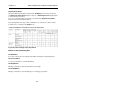
1
CoCut Professional for CorelDRAW 6-10
Illustrator 8, 9, 10
Freehand 8, 9
AutoCAD LT98, R14, 2000, 2000LT, 2000i
User Manual
IMPORTANT CUSTOMER INFORMATION
Important Customer Information about CoCut
Professional
Please check the contents of your software package as soon as possible upon receiving
it. Should any items be missing, immediately contact the dealer from whom you have
purchased the software.
A complete package of CoCut Professional should contain the following items:
• 1 CD
• Copy protection key/dongle
• User manual
• Registration card
Besides the program disks, the most crucial item is the copy protection key/dongle. The
number printed on the dongle must match the serial number located inside the front
cover of your manual.
Underneath the dongle number, you will find your personal code (e.g. 1234567,
123456). This code number must be entered upon successful installation and initial
startup of the software. Make sure you enter the number correctly, or you will not be able
to restart the program.
I
IMPORTANT CUSTOMER INFORMATION
Dear Customer,
In an effort to help you solve any problems and answer your questions as quickly and
efficiently as possible, we provide our Technical Support Line. This is a toll free
number you can call if you have any technical questions about our products.
This service is available to you free of charge.
Mon. - Fri. from 9.00 am to 12.00 am
Mr Holz Phone ++49 6502 9288 11
You can find further useful information including tips and tricks on our web site:
http://www.eurosystems.lu
under the rubric Support.
Our support staff have been instructed only to provide assistance to registered users.
When calling, faxing or e-mailing, please provide the following information:
- Dongle number of your EUROSYSTEMS product
- Version number, i.e. CoCut Professional 6-10
- Date of manufacture of your original program disks
Please understand that we can only answer enquiries addressed to this telephone
number. Other telephone numbers are reserved for marketing, purchasing and sales.
In order to obtain the best possible technical support, we urge you to register your
software. Immediately upon receipt of your registration card by fax or online, you will be
entered in our Customer Support database. This allows us to keep you up-to-date on
revisions and upcoming products.
P.S. For written queries or instant registration by fax or online, please use the following
number or address:
Fax: ++49 6502 9288 15
Web site: h t t p : / / w w w . e u r o s y s t e m s . l u
II
TABLE OF CONTENTS
Table of Contents
Copyright
1
Limitation of Liability
1
Trademarks
1
Hardware and Software Requirements
3
Incompatibilities
3
User Manual Format
3
Visual Aid Chart
4
Introduction
5
What CoCut Professional Can Do
5
1. How to Install CoCut Professional
7
Hardware and Software Requirements for CorelDRAW 6, 7, 8, 9 & 10
7
Installing Windows and CorelDRAW™
8
Windows 95, 98 and ME
8
Configuring the Serial Port
8
Attaching the Dongle
8
CoCut Professional Installation
10
Linking CoCut Professional Script with the CorelDRAW 6 toolbar
12
Linking CoCut Professional Script with the CorelDRAW 7 toolbar
12
Linking CoCut Professional Script with the CorelDRAW 8 toolbar
12
Linking CoCut Professional Script with the CorelDRAW 9 toolbar
12
Linking CoCut Professional Script with the CorelDRAW 10 toolbar
12
Where can I find CoCut in Freehand 8, 9 & 10?
13
How can data be exported from Freehand to CoCut ?
Where can I find CoCut in Adobe Illustrator 8,9?
13
14
How can data be exported from Illustrator CoCut ?
14
Where can I find CoCut in the various AutoCAD versions?
14
I
TABLE OF CONTENTS
Installation of Menu File for AutoCAD LT 98
14
Installation of the Menu File for AutoCAD R14
14
Installation of the Menu File for AutoCAD 2000LT & 2000
14
Installation of the Menu File for AutoCAD LT98 and R14
15
Setting Up the Port for Data Transmission
17
Windows 95® , 98®, ME®
17
Windows NT® & 2000®
17
2. How to Work with CoCut Professional
18
2.1 Your Desktop with the CoCut Professional Working Area
18
2.2 Explanation of Cursor Shapes in the Working Area
19
2.3 The Toolbox
20
2.3.1 The Arrow Tool
20
• Select
20
• Move
20
• Resize
20
2.3.2 The Zoom Tool
21
2.3.3 Other Tools
22
The Register Marks Function
22
The Measuring Tool
22
The Welding Tool
23
2.4 The Object Attributes Dialog Box
26
2.4.1 The Size Option
27
2.4.2 The Position Option
28
2.4.3 The Skew/Rotate Tool
30
2.4.4 The Duplicate Command
31
2.5 The Print Command
33
The Adapt Command
34
II
TABLE OF CONTENTS
The Preview Window in the Adapt Mode
34
Mouse Functions in the Preview Window (Adapt Mode)
34
Printer
35
What is to be printed ?
36
Objects
36
Objects with Worksheet
36
All Objects
36
Selected Objects
36
Printing Color-Separations
36
Print Single Colors (Layers)
36
Relation
36
Center
37
Tile
37
Number of Copies
37
1:1
37
Adjust
37
Print Colored Worksheet
37
Print Guidelines
37
Always Print Black
37
Register/Crop Marks
38
Buttons in the Print Dialog Box
38
The OK Button
38
The Cancel Button
38
The Help Button
38
The Setup Button
38
The Tile Mode
39
Mouse Functions in the Preview Window (Tile Mode)
III
40
TABLE OF CONTENTS
Example of Printing in the Tile Mode
40
Vertical and Horizontal Overlap
42
Activated and Deactivated Tiles
43
2.6 The Cutting Command
45
The CoCut Cutting Dialog Box
45
Why Use a Serial Plotter Drive ?
45
The Cutting Preview Window
50
POWERweed
51
The Options Menu
53
The Rotate Axis Command
53
The Horizontal (X) and Vertical (Y) Mirror Command
53
The Optimize Output Command
54
The Duplicate Command
56
The Position Command
57
The Recalculate Command
59
The Original Display Command
59
The View Menu
59
Total working area
59
The Show All Command
59
The Show Selected Object Command
60
Total Area
60
Job Sectioning in the Cutting Dialog
60
Modifying Sectioning
61
Color Separation in Cutting
62
Common Difficulties Encountered During the Cutting Process
63
a) Vinyl Bunches Up
63
b) Excessive Cutting Speed
63
IV
TABLE OF CONTENTS
c) Excessive Cutting Pressure
63
d) Insufficient Cutting Pressure
63
e) Excessive Cutting Depth
64
f) Dull Cutting Blade
64
g) Small Graphics Separate from Liner
64
h) Liner Cut Through
64
2.7 CMX Import
65
2.8 Description of the Right Mouse Button Menu
66
2.9 Access to RCS ONLINE
66
3. Reference Section
67
3.1 The File Menu
67
• The Open…Command
67
• The Save Command
67
• The Save As… Command
67
• The Export Command
67
• The Online Service… Command
67
• The Print Command
68
• The Cut/Plot Command
68
• The Quit Command
68
3.2 The Editing Menu
68
• The Undo Command
68
• The Redo Command
69
• The Cut Command
69
• The Copy Command
69
• The Paste Command
69
• The Paste Contents... Command
69
• The Select All Command
69
V
TABLE OF CONTENTS
• The Delete Command
70
• The Duplicate Command
70
• The Ready to Cut ... Command
70
3.3 The Design Menu
71
• The Object Attributes ... Dialog Box
71
• The Group Command
71
• The Ungroup Command
71
• The Combine Command
71
• The Break Apart Command
72
• The Draw Command
72
• The Register Marks Function
72
• The Perforation Mark/Drill Hole Function
72
• Clockwise Rotation of Objects
73
• Counter-Clockwise Rotation of Objects
73
• The Close Contour Command
73
• The Open Contour Command
73
• The Round Corners Command
73
3.4 The View Menu
74
• The Zoom In Command
74
• The Zoom Out Command
74
• The Full Page Command
74
• The Show All Command
74
• The Show Selected Object Command
74
• The To Front Command
75
• The To Back Command
75
VI
TABLE OF CONTENTS
• The Forward One Command
75
• The Back One Command
75
• The Reverse Order Command
75
• The Always in Front Command
75
• The Refresh Screen Command
75
3.5 The Tools Menu
76
• The Contour Line... Function
76
• FotoCUT
80
The FotoCUT Dialog Box
80
General Settings
81
Pixels in X Direction
81
Pixels in Y Direction
81
Remaining Width
81
Minimal Grayscale
81
Negative
82
Reverse Direction (only for lines)
82
Double (only for lines)
83
Horizontal or Vertical
84
Bitmap
84
Weed Aid
85
Create Weed Aid
85
Strap Width
85
Strap Thickness
85
Stripes per Strap
87
Modes:
87
• The Set Aligning Marks Command
88
VII
TABLE OF CONTENTS
• The Measure Tool
93
• The Welding Tool
93
3.6 The Settings Menu
93
• The Basic Settings ... Option
94
• Diverse...
94
• Mouse
95
• Plotter
95
• Set Register or Aligning Marks
96
• Working Area
96
• The Rulers... Function
97
• The Measurement Unit Function
97
• The Edit Wireframe Mode
97
• The Undo/Redo command
97
• The Show Tool Box Command
98
3.7 The Help Menu
98
• About CoCut...
98
• Help...
98
• Info...
98
• Online Support
98
4. CoCut Professional Tips & Tricks
99
Glossary
104
Cable Configuration and Baud Rate
108
Aristo
108
Grapfityp
108
Houston
109
Mimaki
109
Mutoh
110
VIII
TABLE OF CONTENTS
Perigraf
110
Roland
111
Summagraphics D and T series
111
Zünd
112
Index
114
Imprint
118
IX
ABOUT THIS MANUAL
Copyright
Copyright©2001 by EUROSYSTEMS S.à.r.l., Luxembourg. All rights reserved.
The CoCut Professional software for Windows and this publication are licensed property
of EUROSYSTEMS S.à.r.l, Luxembourg, 18, Op der Heckmill L-6743 Grevenmacher.
Any reproduction or transmission in any form, by any method or for any purpose of the
software and of this manual, in whole or in part, is strictly prohibited.
User manual text/ typesetting/ layout:
Peter Bettendorf, Georg Wagner
EUROSYSTEMS
English translation: Hilary Teske
This software is licensed for the exclusive use of the original purchaser and is to be used
on one computer system only. Similar to a book, this software can be moved from one
location or computer to another, as long as there is no possibility of it being used at two
locations, or by more than one person, simultaneously.
The licensee may make one copy of the software for backup purposes only.
Limitation of Liability
Utmost care has been taken in the compilation of this manual and the text and
illustrations therein; however, no guarantees can be made as to the completeness or
perfect accuracy of the manual or the program itself.
In no event shall EUROSYSTEMS, its dealers or distributors, be liable for lost profit, data,
or information of any kind, or for any special, collateral, incidental, consequential,
indirect, punitive, or any other type of damages in connection with or arising out of
purchase or use of CoCut for Windows or its documentation. The information contained
in this manual is subject to change without notice and does not represent a commitment
on the part of the vendor.
Trademarks
Adobe Type Manager, AMD, Intel, CorelDRAW, Postscript, Microsoft, Windows, and
other brand or product names used in this manual are trademarks or registered
trademarks of their respective holders/ manufacturers.
1
ABOUT THIS MANUAL
2
ABOUT THIS MANUAL
Hardware and Software Requirements
•
Minimal requirement is a 486 DX with 8 MB of RAM, a Pentium 350 with 64 MB of
RAM is recommended
•
Windows 95 or later version
•
Video Display running at 800 x 600 pixels with 16 colors
Incompatibilities
There are known incompatibilities with certain IBM computers (Value Point Series 486
DX2/66 with PC-DOS prior to version 6.3) and with 386/40 computers from AMD. The
processor boards from these series of computers can create problems with the coprocessor.
Driver incompatibilities can occur with Logitech mice and some high-resolution graphics
cards from various manufacturers; however, these problems can generally be eliminated
by updating the drivers.
User Manual Format
To make this manual more easily readable, the same symbols and type styles are used
throughout. The following is an explanatory chart designed to help you find and interpret
these visual aids more easily.
3
ABOUT THIS MANUAL
Visual Aid Chart
Symbol / Type style
Interpretation
Bold
Headings
italic, bold, colon
Notes:
italic
Note text
italic, bold
Menus, e.g. File menu functions, fields, options,
commands, icons, e.g. New command
CAPITALS
Keys, e.g. SHIFT
KEY1+KEY 2
The plus sign (+) between two keys means that you
have to hold down the first key when you press the
second key. Then you release both keys.
KEY1,KEY 2
A comma (,) between two keys means that you
press the keys one after the other and release them.
Shortcut
4
ABOUT THIS MANUAL
Introduction
CoCut Professional™ is add-on software for cutting vinyl from CorelDRAW™. On
account of its wide range of graphic possibilities, CorelDRAW is eminently suited to
producing high-quality drawings that can easily be printed using powerful printer drivers.
If you, however, wish to use cutting plotters, you may encounter major difficulties due to
the lack of a standard language for driving plotters and the different output formats.
A solution to these problems is to use stand-alone cutting software, which is often
completely isolated, thus making it impossible to exchange data with other systems or
programs such as word processing or design applications.
What CoCut Professional Can Do
•
CoCut Professional is able to work with many different plotters and adapt to their
particular features.
•
Among these are plotters of well-known manufacturers such as Summagraphics,
Mimaki, Roland, Gerber, Zünd, etc.
•
Justification tool for contour cutting of digital printings for cutters (Summa and
Roland)
•
Save-Function
•
EPS-Export
•
CoCut Professional automatically converts lines to cuttable contours.
•
Cutting by color and precise mounting using register marks
•
Color welding: user-defined color overlaps and screen-printing overlaps with userdefined color sequence.
•
Cutting preview on vinyl width and display of the amount of vinyl used.
•
Positioning, resizing, duplicating, etc. of objects.
•
CoCut Professional is integrated into CorelDRAW as an export filter, enabling you
to export your data at the touch of a button. CoCut Professional evaluates the data
produced by CorelDRAW and prepares them for output on the selected plotter.
•
CoCut Professional can cut even extremely large drawings without any difficulty.
You can resize and segment your drawings to any scale you wish, no matter what
the size of the drawing in CorelDRAW.
5
ABOUT THIS MANUAL
•
If the drawing is too wide for your plotter, it will be automatically sectioned, i.e.
divided so that your plotter can cut it.
•
You can set up default values for printing and speed for different materials. These
values can be stored in a material database for reuse at any time.
•
When your plotter is cutting, you can continue working with CorelDRAW or any
other Windows program. The plotter drive works in the background..
6
Chapter 1
INSTALLATION
1. How to Install CoCut Professional
General information on installation.
Hardware and Software Requirements for CorelDRAW 6, 7,
8, 9 & 10
The system requirements for CoCut Professional™ are the same as for the CorelDRAW
version you are using.
CoCut Professional will not work properly unless your system is correctly configured for
using CorelDRAW.
To use CoCut Professional 6, 7, 8, 9 and 10 you need the following equipment:
•
A PC with 80486 DX2 66mhz co-processor for CorelDRAW 6 and a Pentium 60
processor for CorelDRAW 7. A Pentium II 350 is recommended for CorelDRAW
versions 7, 8 & 9. Unlike CorelDRAW, CoCut Professional does its calcutlations with
floating point numbers on account of the high degree of accuracy required. A
numeric co-processor is essential.
•
16 MB of RAM or 32 MB of RAM are strongly recommended
•
Microsoft Windows 95 , 98 or NT CorelDRAW 6, 7, 8, 9 and 10 are not
compatible with Windows 3.1
®
®
®
®
•
Please use only the cable supplied by your plotter manufacturer for transmitting data
from your computer to your plotter. If you encounter any problems, please contact the
manufacturer or your dealer for assistance.
•
As CorelDRAW is a very large program, you will need 250 MB of RAM on your hard
drive. For a typical installation you will need more than 200 MB of RAM. So that you
can work without any problem, your system should have 100 MB of RAM.
•
If you are loading CorelDRAW™ from a CD, the import and export filters will be
copied to your hard drive and stored in the FILTERS subdirectory of the CorelDRAW
directory.
In this case, don’t forget to insert the CorelDRAW CD in your CD-ROM drive before
starting to install CoCut Professional.
7
Chapter 1
INSTALLATION
Note: Close all Windows programs except the Program Manager. If you fail to do this,
errors may occur in updating some of the system files.
Installing Windows and CorelDRAW™
Before you install CoCut Professional, both CorelDRAW and Microsoft Windows 95, 98
or NT must be installed and ready for use. If this has not been done, first install your
version of Windows and then CorelDRAW. Make sure that CorelDRAW works properly
by making a test printout.
Windows 95, 98 and ME
•
•
•
•
Insert the CoCut Professional installation CD in the CD drive.
Click on the Windows Start button and select Execute.
Irrespective of your drive name, type e:\setup.exe or b:\setup.exe in the command
line.
Activate the OK button to start the installation.
Note: See that the Script-Compiler is also installed with CorelDRAW 6 to ensure that
CoCut Professional is correctly installed. This option is automatically selected if you are
doing a complete installation.
Note: Errors which may occur in installation and ways to remedy them are described
later in this manual.
Configuring the Serial Port
For CoCut Professional to work properly it is essential that the parameters are the same
on both plotter and serial port, i.e. the Baud rate, Data bits, Parity, Stop bits and
Flow control are configured identically.
Standard parameters are as follows:
Baud rate: 9600 , Data bits: 8, Parity: none, Flow control: Hardware
Note: The parameters recommended in your plotter software instructions have to match
the settings made when you install CoCut Professional, otherwise conflicts may arise.
Attaching the Dongle
It is necessary to have a dongle to operate CoCut Professional.
This is the small black box in the CoCut Professional package. The dongle has to be
plúgged into a free parallel port on your computer. If you plug in the dongle between
your computer and a printer, the printer must in any case be switched on and online
8
Chapter 1
INSTALLATION
when you wish to cut, otherwise the dongle will not work properly. For this reason we
recommend plugging it into a free parallel port without a printer.
9
Chapter 1
INSTALLATION
CoCut Professional Installation
CoCut Professional 10 comprises one CD.
Step 1:
Plug the dongle supplied with CoCut into your computer’s parallel port
(printer port LPT1). Secure the dongle by tightening the two screws.
Step 2:
Windows 95 & 98 & ME:
Choose the Port icon under icon under Start/Settings/Control
Panel/Device Manager
Windows NT and 2000:
If you are using Windows NT as operating system you will find the Port
icon under: Start/Settings/Control Panel.
Select the port to which your plotter is connected (e.g. COM1).
The standard parameters are as follows:
Baud rate:
Data bits:
Parity:
Stop bits:
Flow control:
9600
8
none
1
Hardware
Check the other settings, which should be as follows:
COM 1: I/O address 03F8 and IRQ 4
COM 2: I/O address 02F8 and IRQ 3
Step 3:
Windows 95, 98, NT and 2000:
Select Execute in the Start Menu.
Insert the CD in CD drive.
Type A:\setup or E:\setup in the command line depending on the name
of your disk or CD drive.
After a short time a window with the title “CoCut Professional Setup“
appears.
Step 4
Use the Continue button to proceed with the installation routine.
10
Chapter 1
INSTALLATION
“EUROSYSTEMS Licencing Agreement“ Dialog Box
Once you have accepted the conditions of the EUROSYSTEMS licencing
agreement, the actual installation is started.
“User Information“ Dialog Box
Type your personal data (name, company, serial number) here.
Example: Serial number: 012345-xy-1-123456-654321
“Select Target Path“ Dialog Box
In this dialog box you can select the directory in which CoCut
Professional is to be installed. C:\EUROSYSTEMS\COCUT is the
default suggestion.
If you wish to install CoCut Professional in another directory, please
activate the Search button and in the dialog box which appears enter the
desired target directory under Path.
“Select Program Folder“ Dialog Box
Here the EUROSYSTEMS folder is the default suggestion. You can
define a new program folder in the Program Folder command line.
Wait for the prompt to change the disk and then follow the further
instructions.
“Setup Ended“ Dialog Box
Confirm this dialog box using the Quit button.
Step 5
Close all applications and restart your computer.
11
Chapter 1
INSTALLATION
Linking CoCut Professional Script with the CorelDRAW 6 toolbar
•
•
•
•
•
•
Select the menu Tools/Customize
Click on the Toolbars tab
Double-click on Script Applications
Select from the General Scripts folder the script CoCut 6 Professional.csc.
Choose any symbol you wish and drag it to the CorelDRAW toolbar with the left
mouse button held down.
Click on OK in the Customize dialog box
Linking CoCut Professional Script with the CorelDRAW 7 toolbar
•
•
•
•
•
Select the menu Tools/Customize
Click on the Toolbars tab
Select from the Application Scripts folder the script CoCut 7 Professional.csc.
Choose any symbol you wish and drag it to the CorelDRAW toolbar with the left
mouse button held down.
Click on OK in the Customize dialog box
Linking CoCut Professional Script with the CorelDRAW 8 toolbar
•
•
•
•
•
Select the menu Tools/Options
From the left-hand set of options select Workspace/Customize/Toolsbars
Select from the Application Scripts folder the script
CoCut 8 Professional.csc.
Choose any symbol you wish and drag it to the CorelDRAW toolbar with the left
mouse button held down.
Click on OK in the Options dialog box
Linking CoCut Professional Script with the CorelDRAW 9 toolbar
•
•
•
•
•
Select the menu Tools/Options
From the left-hand set of options select Workspace/Customize/Toolsbars
Select from the Application Scripts folder the script CoCut 9 Professional.csc.
Choose any symbol you wish and drag it to the CorelDRAW toolbar with the left
mouse button held down.
Click on OK in the Options dialog box
Linking CoCut Professional Script with the CorelDRAW 10
toolbar
Important note: CorelDRAW must be installed with the “Visual Basic for Application.”
12
Chapter 1
INSTALLATION
This option can be installed as follow:
Insert the CorelDRAW 10 CD in the disk drive / Start setup / Select “Customize setup”.
If a CorelDRAW 10 version already installed on your computer, first select ” User-defined
setup” and then “Customize setup”. In the dialog which now opens double-click on Main
Applications or click once on the Plus. Double-click on Productivity Aids and select
“Visual Basic for Application”. After installing CoCut you have to link the CoCut script
with the menubar.
•
Select the menu Tools/Adjustment
•
From the left-hand set of options select Workspace/Customize/Command
•
Click once in the File box on the right of the list of options, select Macros and drag
CoCut10Prof.CoCut... to the menubar of CorelDRAW 10.
•
Now select the Appearance tab. Click on the Import button and select any
symbol you want.
•
Note: The symbol disappears every time you restart CorelDRAW and the bookicon (standard default-icon) appears. (CorelDRAW Bug)
•
From the left-hand set of options select Workspace/Customize/Command
•
Change the name of the”New sysmbol bar 1” to CoCut Professional.
•
Click OK in the Options dialog box
Where can I find CoCut in Freehand 8, 9 & 10?
You can find CoCut in Xtras and in the Window menu/Xtras.
How can data be exported from Freehand to CoCut
?
Start CoCut and if objects are selected, only the selected objects will be exported to
CoCut.
Start CoCut and if no objects are selected, all object located in your working area will be
exported to CoCut.
Restriction: Fountain fills and lens effects are not supported.
13
Chapter 1
INSTALLATION
Note: Freehand 8 has a color correction mechanism (like, for example, CorelDRAW)),
which affects the display of colors in Freehand.
Solution: Turn off this function via File/Setting/colors.
Where can I find CoCut in Adobe Illustrator 8,9?
You can find Corun in the File menu.
How can data be exported from Illustrator CoCut ?
Start CoCut and if objects are selected, only the selected objects will be exported to
CoCut. Any texts to be exported will automatically converted to curves.
Note: If no objects are selected, the CoRun auto export filter is not active.
Restriction: Special fountain fills are not exported.
Where can I find CoCut in the various AutoCAD versions?
Installation of Menu File for AutoCAD LT 98
Select Adjust Menus in the Extras menu. In the dialog box appearing click on the
Scroll button. This opens the File Selection dialog box. Set the file ending to *.mnu um.
Select the cocut.mnu file and close the dialog box.
Click on the Load button and then on OK in the enquiry dialog box.
The CoCut menu has now been loaded.
Now switch to the Menu Bar dialog box in the upper tab. Select CoCut Plot and insert it
in the desired place in the AutoCAD menu.
CoCut is now to be found in the menu list and a CoCut toolbar is added to the toolbars.
Installation of the Menu File for AutoCAD R14
Select Adjust Menus in the Extras menu. In the dialog box appearing click on the
Scroll button. This opens the File Selection dialog box. Set the file ending to *.mnu um.
Select the cocut.mnu file and close the dialog box.
Click on the Load button and then on OK in the enquiry dialog box.
The CoCut menu has now been loaded.
Now switch to the Menu Bar dialog box in the upper tab. Select CoCut Plot and insert it
in the desired place in the AutoCAD menu.
CoCut is now to be found in the menu list and a CoCut toolbar is added to the toolbars.
Installation of the Menu File for AutoCAD 2000LT & 2000
14
Chapter 1
INSTALLATION
Select Adjust Menus in the Extras menu. In the dialog box appearing click on the
Scroll button. This opens the File Selection dialog box. Set the file ending to *.mnu um.
Select the cocut.mnu file and close the dialog box.
Click on the Load button and then on OK in the enquiry dialog box.
The CoCut menu has now been loaded.
Now switch to the Menu Bar dialog box in the upper tab. Select CoCut Plot and insert it
in the desired place in the AutoCAD menu.
CoCut is now to be found in the menu list and a CoCut toolbar is added to the toolbars.
Installation of the Menu File for AutoCAD LT98 and R14
Select Printer Setup in the File menu. In the dialog box appearing click on the Open
button and select the cocut/t98.pc2 (LT98) file or cocutr14pc (R14) file. Quit the
dialog box.
Now start a printing job by clicking on Print in the File menu to make the following
settings:
Click on Plot to File, set the Resizing Factor to 1:1 and the Unit to mm.
Note: Make sure the Plot To File checkbox is activated when making the first plot.
This procedure ensures that all drawing elements are transmitted.
The Pen Change commands from the Plot file are interpreted so that 8 layers can be
separated.
AutoCAD does not plot with arcs, i.e. all elements are converted into lines and dots are
interpreted as drill holes.
Note: If you are using DXF, you have to press RETURN twice after selecting the object,
as the execution of the menu macros is interrupted by the object selection.
Note: With export via DXF lettering and texts are not exported, but it is possible to select
objects and plot them. The curves are not converted to lines but are changed from the
splines or arcs in the DXF file into Bezier curves.
Note: The number of layers is not restricted to 8.
In the Windows autostart group a connection to the autoimp.exe program is made during
installation, so that the data can be exported to CoCut. When autoimp.exe is started, an
icon will be displayed in the system bar at the bottom right of the screen.
The program can be ended by making a double click on this icon.
Note: If the icon is turned off, the data will not be exported to CoCut.
The program can be restarted via Start/Programs/Autostart/ Auto-Import for CoCut.
15
Chapter 1
INSTALLATION
Note: When installing, make sure that CoCut for AutoCAD is only installed for the last
used AutoCAD version when several AutoCAD versions are installed on your computer.
16
Chapter 1
INSTALLATION
Setting Up the Port for Data Transmission
Windows 95 , 98 , ME
®
•
•
•
•
•
•
•
•
•
®
Click on the Start button and select Control Panel.
Double-click on the System icon.
Click on the Device Manager tab.
Click once on the + sign.
Double-click on Port.
Double-click on the port to which your plotter is connected. (e.g. COM2).
Click on the Port Settings tab.
Set the flow control to Hardware and make the other settings to match the default
settings of your plotter (manual).
Click on the Close button.
Windows NT & 2000
®
•
•
•
•
•
•
•
®
®
Click on the Start button and select Settings.
Click on the Control Panel tab.
Double-click on Port.
Double-click on the port to which your plotter is connected (e.g. COM2).
Click on the Settings button.
Set the flow control to Hardware and make the other settings to match the default
settings of your plotter (manual).
Click on the Close button.
17
Chapter 2
HOW TO WORK WITH COCUT PROFESSIONAL
2. How to Work with CoCut Professional
2.1 Your Desktop with the CoCut Professional Working
Area
In this chapter you will learn the basics of working with CoCut Professional. You will be
introduced to such items as the desktop, the tools, the text editor, data import and export,
loading and saving jobs, as well as cutting.
After CoCut has been started, the following window appears:
A)
B)
C)
D)
E)
F)
G)
H)
I)
J)
K)
L)
M)
N)
O)
System field
Window title
Title line
Button
„Symbol“
Button
„Full screen“
Button
„End“
Toolbox
Menu line
Object attributes
box
Vertical scroll bar
Working area
Rulers
Mouse
coordinates
Status bar
Measurement
unit
Fig. 1: The CoCut Professional Working Area
Note: In CoCut the horizontal scroll bar and the status bar are combined. The bar
switches between the two functions when the mouse cursor is directed to part of it.
The rulers can be positioned freely or completely turned off.
The units of measurement (cm, mm, inch) can be changed by simply clicking a button.
The button is located in the lower right corner where the horizontal and vertical scroll
bars meet.
18
Chapter 2
HOW TO WORK WITH COCUT PROFESSIONAL ?
In the status bar there is extensive information about the objects to be found on the
working area, such as wireframe, fill, dimensions, number, combination or grouping.
The various elements in the menu line will be dealt with in detail in the Reference
Section.
2.2 Explanation of Cursor Shapes in the Working Area
No object selected
Note: Select objects by positioning the mouse cursor on the object and pressing the left
mouse button.
Move objects
Note: This type of cursor is only active when the cursor is located in the interior of the
object or in the area between the 8 black squares on the wireframe. The object must be
selected.
Enlarge object vertically
Enlarge object horizontally
,
Enlarge object diagonally
Note: The cursors for changing the size of objects are only active when the cursor is
located in the area between the 8 black squares on the wireframe of the object.
You can switch into the Skew/Rotate mode by clicking once on the left mouse button
with the cross cursor activated.
Object in Skew/Rotate mode
,
,
,
,
Rotate object
Skew object
19
Chapter 2
HOW TO WORK WITH COCUT PROFESSIONAL
2.3 The Toolbox
Upon initial start-up of CoCut, you will find the toolbox in the upper left corner of your
screen. It contains 5 icons.
Fig. 2: The CoCut Professional Toolbox
Note: Redisplay the toolbox via Show Toolbox in the Settings menu.
The toolbox can be moved at any time by clicking the bar at the top and dragging it to the
desired location. When you exit the program, CoCut will save the last position of the
toolbox.
2.3.1 The Arrow Tool
Fig. 3: The Arrow Tool
The arrow tool, also known as the general work tool is used to select, move, temporarily
group and resize text or objects
• Select
Click on any point of the object and it is automatically selected, i.e. a frame defined by
eight small squares appears around it. When working in the Edit Wireframe (F9)mode,
you must click on the outline of the object to select it
Note: To select individual characters in a text string, the text must first be converted to an
image by using the Text to Curves command in the Edit menu. The selected letter(s)
can then be detached from the string by pressing SHIFT+L.
• Move
You can move objects by selecting them and dragging them to the required positon on
your working area with the mouse button held down.
• Resize
You can proportionally resize objects by grabbing one of the 4 handles or corner squares
of the frame around the object. Double-clicking on one of these corner squares opens
the Object Attributes...dialog box in which you may enter specific values under Size.
20
Chapter 2
HOW TO WORK WITH COCUT PROFESSIONAL ?
To resize an object non-proportionally, double-click on the squares located between the
corner markers.
To resize by eye (proportionally or non-proportionally), simply click on the appropriate
square and drag it until the desired size has been attained.
2.3.2 The Zoom Tool
This function is used to zoom in and out on your desktop, working area or design.
Fig. 4: The Zoom Tool Icon
When you click on the Zoom icon, a flyout box appears containing five additional icons
Fig. 5: Flyout with 5 Zoom Functions
The icon with the plus sign is used to enlarge a selected area of your desktop. Using the
framing function, draw a frame around the area you want to enlarge. You can repeat this
procedure several times for further magnification. An acoustic signal will warn you when
you have reached the limit and no further magnification is possible.
Note: You can also activate this command by pressing F2 and the + (plus) key in the
numeric keypad.
The icon with minus sign is used to reduce a selected area of your desktop or working
area.
Note: You can also activate this command by pressing F3 and the - (minus) key in the
numeric keypad.
The icon depicting a sheet of paper symbol is used to view the working area in its
entirety.
The icon depicting a monitor is used to display all objects in your working area. CoCut
will enlarge or reduce the objects to make just enough room for everything to fit on your
screen.
The last icon depicting a magnifying glass is used to display all selected objects in the
meximum size.
21
Chapter 2
HOW TO WORK WITH COCUT PROFESSIONAL
Note: If you hold down the SHIFT key while executing this command, only the selected
objects will be enlarged to their optimal size.
2.3.3 Other Tools
When you click on this icon a fly-out box appears with the following functions:
Fig. 6: The Tools Icon
The Register Marks Function
Fig. 7: The Register Marks Icon
With this option you can place register (crop) marks in your image. To do so, activate the
command and click the register marks to the required position. Register marks will be cut
in every layer.
Aktivieren dazu diesen Befehl und klicken Sie die Passermarke an die gewünschte
Position. Register marks will be cut in every layer regardless of its color.
The Measuring Tool
Fig. 8: The Measuring Tool
The measuring tool is used to perform measurements (between any two points) in your
design. As soon as you click on the Measure icon in your tool box, the cursor changes
into a bull’s eye. Move the center of the bull’s eye to the first point, i.e. the point from
which you intend to measure.
While holding down the left mouse button, drag the bull’s eye to the second point, i.e. the
end-point of the distance you are measuring. A guideline provides a visual connection
between the two points.
Note: If you hold down the SHIFT key during this procedure, the measuring can be
limited in a horizontal or vertical direction. This makes it easier to measure straight lines
accurately.
22
Chapter 2
HOW TO WORK WITH COCUT PROFESSIONAL ?
Fig. 9: The Measure Dialog Box
The Length field indicates the result of your measurement. To change this value, click
the field and enter the new length. You can also make changes to the percentage field
below.
The dialog box provides additional information such as the angle of the line you
measured, the width of the object you measured and the difference in height between the
first (beginning) and second (end) point.
The Welding Tool
Fig. 10: The Welding Tool
This tool is used to combine two or more selected objects into a single one by joining
overlapping areas and deleting extra lines.
If there are objects containing line attributes or fills in the CoCut Professional working
area, the following dialog appears after you have clicked on the Cutting button:
Fig. 11: Dialog Box for Converting Lines and Gradient Fills
23
Chapter 2
HOW TO WORK WITH COCUT PROFESSIONAL
In this dialog box you have the possibility to convert line attributes and gradient fills to
curves. If there are objects with pencil attributes and the Convert Lines command is not
activated, the lines attributes will not be taken into account during cutting. If there are
objects with gradient fills and the Convert Gradient Fills command is not activated, the
gradient fills will not be taken into account during cutting.
Depending on the number and design of the selected objects you can choose between
the following options:
Automatic, By Color, Full Surface or Screenprint.
The other fields depend on which option you select and are therefore described in the
relevant section.
Fig. 12: The Welding Dialog Box
One of the main applications for automatic welding is to weld serifs used in script fonts,
since serifs of one letter tend to overlap with those the next, which is, of course,
something you want to avoid.
Automatic welding eliminates these overlaps and creates smooth transitions from one
serif to the next, which can then be cut cleanly and applied as a continuous piece. Should
you find certain parts of the letters missing after performing an automatic weld, select the
Undo command and reduce the character spacing from 100% to 99%.
24
Chapter 2
HOW TO WORK WITH COCUT PROFESSIONAL ?
This will cause identically positioned nodes to move just enough so that they can be
recognized by CoCut as individual nodes, which will make it possible for the automatic
welding process to be completed properly.
The By Color option removes all areas covered by overlying colors. It does not matter
how many objects and colors you select.
If some of the selected objects have open contours, you can close them or add a line of a
specified width. This is described in the Automatic section.
It may happen that the same color appears in various color layers. If you perform the
command Merge Same Colors, such layers will be combined in a single layer.
You can generate an Overlap or an Offset at the point where two colors meet.
Select Overlap or Offset in the Seams field and enter the desired amount.
Full Surface underfills objects of one color which are covering areas of another color.
The partially concealed objects are modified so that they underlie the entire surfaces of
the overlying objects.
For open objects you can use the same procedure as described under Automatic.
This application is most useful for shop window lettering which is often difficult to mount
when the By Color option is used. If you have a maximum of two or three colors it is best
to work with the Full Surface option, where the single vinyl colors are stuck on top of
each other.
Screenprint is an especially powerful tool for screen printers.
First of all, the intersections of the single color layers are eliminated. Then the colors are
layered in the sequence specified in the Color Sequence box. Finally a small line is
added as an overlap at the “seams” of the single color layers.
You can determine the desired color layering in the preview window on the right side of
the dialog. Clicking on the mouse lets you “grasp” a layer and drag it to its proper
position. The chart indicates the position of the layers.
In the Seams and Overlap boxes you can enter the desired overlap between the color
layers. In each case the lower layer underlies the higher one.
You also have the possibility of merging recurring colors in one layer.
To do this, select Merge Same Colors.
This option is especially useful for creating templates for screen printing, as in this
printing process the darkest color is always applied last so as to avoid streaks which
might occur when applying the individual colors.
25
Chapter 2
HOW TO WORK WITH COCUT PROFESSIONAL
Note: If your graphic includes objects with open contours, proceed as described in the
section on the Automatic mode.
2.4 The Object Attributes Dialog Box
The Object Attributes .. dialog box can be opened either by double-clicking on one of
the black handles at the edge of the object or by pressing the G key.
The Object Attributes.. dialog box can be used to change the parameters Size,
Position, Skew/Rotate objects and Duplicate objects in a horizontal or vertical
direction at selected intervals.
The Object Attributes... dialog box contains all the functions most frequently required
and considerably speeds up the work on your job. The various functions of the Object
Attributes... dialog box are explained in detail in the following sections.
Note: The three icons in the top right part of the Object Attributes... dialog box are the
same in all modes and have the following purpose:
You can use the Pin icon
to fix the Object Attributes-dialog box firmly to the CoCut
desktop. If you click the Pin icon, the pin will turn into a
replaced by a button labeled Assign.
and the OK button will be
Note: Once the Object Attributes... dialog box has been pinned, it will not be closed
after the desired values have been entered.
26
Chapter 2
HOW TO WORK WITH COCUT PROFESSIONAL ?
2.4.1 The Size Option
Fig. 13: The Size Option
If you select this option, the following box appears:
Fig. 14: The Object Attributes... Dialog Box in the Size Mode
In the Height and Width boxes you can enter the height and width of one or all selected
objects as numbers or percentages.
If you click the All Objects button, the values you enter will apply to all objects.
The two fields are connected to each other, i.e. if the width is changed, the height will
also be modified by the value typed.
If you click the Distort button, you have the possibility to alter the Height and Width
fields separately.
27
Chapter 2
HOW TO WORK WITH COCUT PROFESSIONAL
2.4.2 The Position Option
Fig. 15: The Position Icon
If you click on this option, the following box appears:
Fig. 16: The Object Attributes... Dialog Box in the Position Mode
This option allows you to position your objects anywhere on your working area.
In the X and Y boxes you can enter the horizontal and vertical coordinates relatively and
absolutely in relation to the reference point.
Absolute and Relative Positions
The absolute position means the real X and Y coordinates of the object’s point of
reference.
28
Chapter 2
HOW TO WORK WITH COCUT PROFESSIONAL ?
Reference Point
When the object is selected, the reference points are shown as black squares. These
squares correspond to the circles in the Position dialog box.
Note: The center of the selected object is not marked as a point of reference.
1
Center of Selected Object
1
Fig. 17: Object Center and Reference Point
Example of Absolute Coordinates
If the Relative Position option is chosen, the circles are shown in gray, which means
that they are no longer active. You should set the required point of reference for
repositioning the circles before activating them.
Fig. 18: Example of Abolute Coordinates
In the example (Fig. 18) X and Y values of 50mm (1.96 ins) were entered.
The value of 60mm (2.36 ins) was entered for the relative coordinates to the reference
point, i.e. the reference point was moved 60mm (2.36 ins) both horizontally and vertically.
This results in a new absolute value of 110mm (4.33ins) for the X and Y coordinates.
29
Chapter 2
HOW TO WORK WITH COCUT PROFESSIONAL
2.4.3 The Skew/Rotate Tool
Fig. 19: The Skew/Rotate Tool
If you click on the Skew/Rotate icon in the Object Attributes... dialog box, the
following dialog appears:
Fig. 20: The Object Attributes... Dialog Box in the Skew/Rotate Mode
Fig. 21: Objects in the Skew/Rotate Mode
30
Chapter 2
HOW TO WORK WITH COCUT PROFESSIONAL ?
You can rotate your object by moving your mouse cursor to the round arrows at the
corners of the object and keeping it held down.
When the object has been rotated, its position will be shown by a dotted blue line. You
can see the exact amount of the rotation in the status line on the bottom left of the screen
near the mouse coordinates.
Double-clicking on one of the four round arrows at the corners of your object will activate
the Skew command in the Object Attributes... dialog box.
A positive value rotates objects clockwise, a negative value counter-clockwise.
If you click on one the straight double arrows while holding down the left mouse button,
your object is skewed to the left and right and upwards and downwards. The sides you
click on will be moved, whereas the ones opposite remain the same.
If you activate the Absolute Values command, the absolute angle will be displayed
when the object is rotated or the absolute X or Y coordinates when the object is skewed.
2.4.4 The Duplicate Command
Fig. 22: The Duplicate Command
If you activate this command in the Object Attributes... dialog box, the following dialog
box appears:
Fig. 23: The Object Attributes... Dialog Box in the Duplicate Mode
31
Chapter 2
HOW TO WORK WITH COCUT PROFESSIONAL
Number X
You can enter the number of duplicates in a horizontal direction in this field. The arrows
to the right of this field indicate the direction (right/left) in which the duplication is to be
effected.
Number Y
You can enter the number of duplicates in a vertical direction in this field. The arrows to
the right of this field indicate the direction (upward/downward) in which the duplication is
to be effected.
X Offset
Here you can enter the distance you wish to have between the duplicates in a horizontal
direction in this field.
Y Offset
Here you can enter the distance you wish to have between the duplicates in a vertical
direction in this field.
If the Select Objects command is active, all your objects will be automatically selected
after they have been duplicated.
Click OK to confirm your entries.
32
Chapter 2
HOW TO WORK WITH COCUT PROFESSIONAL ?
2.5 The Print Command
Fig. 24: The Print Icon
The following sections describe the various functions of the CoCut Print dialog box in
detail.
Open the CoCut Print dialog box by selecting Print in the File menu, using the shortcut
CTRL+P on the keyboard or clicking on
the
icon in the tool box.
The following window opens:
Fig. 25: The CoCut Print Dialog Box
33
Chapter 2
HOW TO WORK WITH COCUT PROFESSIONAL
In the lower right part of the dialog you will find under Output the Tile option and the
Adapt button.
The appearance of the Print dialog box changes depending on which button you have
activated. When the Print dialog box is selected, the Adapt button is automatically
activated, because objects or graphics cannot be printed in formats exceeding the
maximum output size of the printer being used.
The Adapt Command
The Adapt command lets you specify the printable area. The values for the printable area
are shown in the Printing Area box located in the upper right part of the Print dialog box.
The Preview Window in the Adapt Mode
This window allows you to recheck your job before it is printed.
The Snap to Edge function permits you to position your objects quickly in the corners or
at the edges of pages.
Tip: If you want to turn off the Snap to Edge function, hold down the SHIFT key while
you position your objects.
The coordinates appearing below the preview window show the position of the upper left
corner of the first object in the working area.
Mouse Functions in the Preview Window (Adapt Mode)
Clicking once with the right mouse button enlarges the preview window to its maximum
size.
The size of the display depends on the screen resolution. (800*600, 1024*768,...).
If you click again with the right mouse button the original state is restored.
If you press and hold down the left mouse button, a dotted black frame appears around
the objects to be printed.
This frame encompasses all objects to be found on the working area and corresponds to
the printing area.
34
Chapter 2
HOW TO WORK WITH COCUT PROFESSIONAL ?
Printing Area
This box shows the height and width of the specified printing area.
Fig. 26: Printing Area and Object
This box shows the height and width of the specified printing area.
Object Attributes Dialog Box
This box displays the object(s) to be printed with its/their heights and widths.
Note: The boxes for the percental enlargement of objects are not active in the Adapt
mode.
Below the Object Attributes... field, on the right side of the Print dialog, you will see
the Printer field.
Printer
Fig. 27: Choice of Printer
If you open the combobox in the upper part of the dialog box, you will obtain a list of all
the printers installed on your system. Select the printer you wish to use.
To make further settings for the printout, click on the Setup button.
The dialog which appears is the same as the menu item Attributes in the Printer File
menu.
Note: The Print dialog box opened by clicking the Setup button depends on the printer
driver loaded and for this reason is not explained in greater detail here.
You can specify the Page Format (upright/oblong) in the field to the right of the Setup
button.
35
Chapter 2
HOW TO WORK WITH COCUT PROFESSIONAL
What is to be printed ?
In the field headed Print Mode there are two comboboxes which you can use to
determine what is to be printed.
In the first box you can choose between Objects, Objects with Worksheet and Job
Info.
Objects
All objects in the working area will be printed.
Objects with Worksheet
All objects and also the worksheet (black frame) will be printed.
The company name, the measurements of the working area and the proportional size of
the printout will also be printed automatically below the black frame.
The following settings are available in the second box: All Objects, Selected Objects,
Print Color Separations (print in layer order), Print Single Layers (colors).
All Objects
All objects on the working area will be printed.
Selected Objects
Only selected objects on the working area will be printed.
Printing Color-Separations
All objects of one color will be printed in the order displayed.
The color bar (layer order) in the second box contains all the colors (layers) which have
been used in the working area. The colors will later be printed in this sequence. The
darkest color is always printed first.
Print Single Colors (Layers)
The colors listed in the second box are those which have been used for the objects on
the working area.
If, for example, there is only a black and a red object in the working area, there will be a
choice of only two color bars (layers) available.
Relation
You can enter the relation in which the printout should be made in one of two boxes,
either as a figure or a percentage. The boxes are coupled, i.e. if you enter a figure, the
equivalent percentage will automatically appear in the box provided and vice versa.
36
Chapter 2
HOW TO WORK WITH COCUT PROFESSIONAL ?
Examples of relation entries in figures with the corresponding percentages:
Relation
Relation
Relation
Relation
1:1
1:2
1:3
1:4
100.00 %
50.00 %
33.33 %
25.00 %
Center
If this option is activated, all objects on the working area will be centered.
Tile
If this option is selected, the Print dialog box appears in the Tile mode.
Number of Copies
In this box the number (max. 9999) of copies to be printed can be specified.
The Adjust and Tile buttons permit you to switch to and fro between these two modes.
1:1
When this button is activated, all objects on the working area will be displayed in their
original size.
Adjust
When this button is activated, the objects in the working area are reduced so that they
can be shown in their entirety in the preview window.
Print Colored Worksheet
If this option is selected, your worksheet will be printed with the specified background
color.
Print Guidelines
If the job contains guidelines, these will also be printed.
Always Print Black
This option will automatically be activated when All Objects is selected in the first box
and Print Color Separations (in layer sequence) or Print Single Colors (single layers)
is selected in the second box.
If you want to print the objects in the working area in color, the command must be
deactivated.
37
Chapter 2
HOW TO WORK WITH COCUT PROFESSIONAL
Register/Crop Marks
This option will automatically be activated when All Objects is selected in the first box
and Print Color Separations (in layer sequence) or Print Single Colors (single layers)
is selected in the second box
If you do not want the register/crop marks to be printed, the Register/Crop Marks
button must be deactivated beforehand.
The following table shows all possible combinations for comboboxes 1 and 2 and the
possible choice of settings in the Adapt mode.
Fig. 28: Possible Settings in the Adapt Mode
Buttons in the Print Dialog Box
The OK Button
If you click on this button the settings made will be transmitted to the printing device.
The Cancel Button
You can use this button to quit the Print dialog
The Help Button
Clicking on this button starts the CoCut Professional help.
The Setup Button
Clicking on this button opens the dialog box for setting up your printer.
38
Chapter 2
HOW TO WORK WITH COCUT PROFESSIONAL ?
Note: The Printing dialog box opened by clicking on the Setup button depends on the
printer driver loaded and for this reason is not explained here.
The Tile Mode
If you switch from the Adjust mode to the Tile mode, the following preview window
appears:
Fig. 29: The Preview Window in the Tile Mode
In the Tile mode all tiles are displayed. A tile is the part of an object which can be printed
or cut on the device being addressed.
Break After indicates after which tile (enter the number of the tile) the output should be
stopped. You can enter the desired horizontal/vertical intersection of the objects to be
printed in the boxes under Overlap.
If you print using Roll, complete stretches can be printed without any spaces between
the single tiles.
You can only stop the printing of a complete stretch and not of the individual tiles.
Entering an intersection in the printing direction does not have any effect on this
operation, as can also be seen from the display of the tile size.
39
Chapter 2
HOW TO WORK WITH COCUT PROFESSIONAL
Note: After tiling, the dialog will not automatically be closed, as it is useful to be able to
compare the preview directly with output. This also allows you reprint a particular tile
immediately.
Mouse Functions in the Preview Window (Tile Mode)
You can enlarge the tiling view to the size of the screen by clicking once with the right
mouse button on the tile preview window. A second click with the right mouse button will
restore the original state.
Double-clicking with the left mouse button on a tile deactivates the tile, i.e. it is not
printed.
If you double-click with the left mouse button while holding down the CTRL key, the tiling
will be inverted, i.e. the tiles which were previously deactivated will be activated (printed)
and the tiles which were activated will be deactivated (not printed).
The objects can be moved within the preview window using the mouse. The Snap to
Edge function enables you to position your objects easily at the edge of the window. You
can turn off the Snap to Edge function by pressing the SHIFT key.
Example of Printing in the Tile Mode
In the following example, the various functions, shortcuts, etc. in the Tile mode are
explained again in detail.
The Tile mode offers you the possibility of printing in any size, i.e. any image, regardless
of its size, can be printed out on the printer connected to your system.
To print your image, you do not require a printer for printing A2, A1, A0 or even large
formats.
How can this be done?
The image to be printed is divided into as many partitions (tiles) as necessary to be able
to print it on the printer connected to your system. .
The number of tiles necessary depends on the size of the image to be printed and the
output format (A3, A2, etc.) which has been specified.
You can determine the output format using the Setup button in the CoCut Print dialog
box. The format depends on the printer which is connected to your system.
Load any image you like to CoCut Professional and open the Print dialog box, either by
clicking Print in the File menu, by pressing CTRL+P on the keyboard or by using the
button in the toolbox.
The CoCut Print dialog box will be opened in the Adapt mode. Activate the Tile mode
by clicking the appropriate button.
40
Chapter 2
HOW TO WORK WITH COCUT PROFESSIONAL ?
The Print dialog box appears as follows:
Fig. 30: The Print Dialog Box in the Tile Mode
In the upper right corner of the dialog box you will see two fields, Tile and Object. The
Tile field corresponds to the Printing Area box in the Adapt mode. The other fields in
the right half of the Print dialog box behave in the same manner as in the Adapt mode.
The preview window in the Tile mode shows all the tiles which are required to print out
the complete image.
Eight pages, for instance, are required to print out the image in the example.
A change in the output format always necessitates an adjustment in the number of tiles.
Beneath the preview window you will find the fields Break After, Tiling and Roll, which
are explained on page 39 of the manual.
41
Chapter 2
HOW TO WORK WITH COCUT PROFESSIONAL
Vertical and Horizontal Overlap
The number of tiles increases depending on the number of vertical or horizontal overlaps
which you have specified. Figure 32 shows two tiles to be printed without any overlap.
Fig. 31: Two Tiles without Overlap
Fig. 32: Four Tiles with Overlap
Fig. 32 shows that the number of tiles increases when you use an overlap.
42
Chapter 2
HOW TO WORK WITH COCUT PROFESSIONAL ?
Activated and Deactivated Tiles
An active tile means a tile which is not marked with an X, whereas deactivated tiles are
always marked with an X.
1
3
5
2
4
6
Fig. 33: Deactivated Tile
Tiles can be deactivated or activated by double-clicking on them with the left mouse
button, i.e. a tile is deactivated with a double click. A further double click will reactivate it.
You can see from Fig. 33 that tile number 4 is marked with an X. This tile has been
deactivated and will not be printed.
In the Tile mode you have a further possibility besides activating or deactivating single
tiles.
If you hold down the CTRL key while double-clicking on the desired tile with the left
mouse button, all tiles, except the one on which the mouse cursor is positioned, will be
deactivated.
Fig. 34 and Fig. 35 illustrate this.
43
Chapter 2
HOW TO WORK WITH COCUT PROFESSIONAL
Mousecursor
Fig. 34: Six Tiles Active (Mouse Cursor is on Tile 4)
Fig. 35: Tiles 1, 2, 3, 5 and 6 Deactivated, Tile 4 Activated
Advantage of deactivating tiles:
When your objects are arranged, tiles without objects (empty tiles) may be created, which
would result in a blank page being printed.
44
Chapter 2
HOW TO WORK WITH COCUT PROFESSIONAL ?
2.6 The Cutting Command
This command allows you to activate the module for cutting and drawing your job data.
The CoCut Cutting Dialog Box
Fig. 36: The CoCut Cutting Dialog Box
In the box titled Plotter/Driver select the device that is connected to your serial port.
Why Use a Serial Plotter Drive ?
The serial RS 232 port is the link for data exchange between the cutting plotter and the
so-called host computer.
The host computer calculates the necessary plotting data decentrally.
Two-way or bidirectional communication takes place between the host computer and
the cutting plotter via a hardware handshake. There is a separate data lead for this
handshake in the original cable supplied by the plotter manufacturer. The centronics port,
i.e. the parallel (printer) port, only permits one-way or unidirectional communication
between the host computer and plotter.
The cutting plotter can receive, but not cut, data using this port. Thus, when using this
port, it not possible to specify the vinyl width, vary the stabbing pressure or reduce the
cutting speed. Only one port at a time can be active, in this case the plotter, as it receives
the data first.
Besides this purely technical difference, there is another important reason, which is the
different distribution of resources with computers using MS Windows 3.xx.
45
Chapter 2
HOW TO WORK WITH COCUT PROFESSIONAL
Whereas serial drive lets you go on working during plotting, the computer is blocked all
the time during plotting, when parallel drive is used.
In this case serial drive means higher productivity.
In the Mode box, select whether you want to draw or cut with your device.
Under Port select the port to which your cutting plotter is connected. This is usually
COM2.
In this box you can also choose File. This selection allows you to send the output data to
a file specified by you and the data will be saved on your hard drive.
In the boxes Material/Vinyl, Pressure, Speed/Velocity and Width you can enter
specific values for the material you are using. These values have to be entered
individually, as they depend on the material and the machine you are using.
The range of values are described in your plotter manual.
For example, the maximum speed is 60 cm/sec, i.e. 60 should be entered under
Speed/Velocity. Other plotter manufacturers use mm/sec as unit of measurement. In
this case a three-digit figure has to be entered, e.g. 150.
To install a new set of material data in the material databank, proceed as follows:
Click with the left mouse button on the New button below the Material/Vinyl box.
Enter the description of the material, e.g. Mactac, 3M, PMF, paper, etc. and specify its
attributes regarding pressure, speed and width.
If you keep the SHIFT key pressed down while you click on the buttons, the current set of
data will be saved as a new set of data.
This is useful when you only want to make small changes, such as different pressure, in
the current entries.
You can save the data by clicking Save.
The Delete button gives you the possibility of deleting individual sets of data again.
Note: The settings in this dialog box will be automatically saved when the Cut/Draw
button is activated.
The Options button lets you set routing parameters and cannot be activated when you
are using the cutting plotter.
With a lot of cutting plotters the Read Back button indicates the height of the plottable
area so that the value for Width does not have to be entered manually.
46
Chapter 2
HOW TO WORK WITH COCUT PROFESSIONAL ?
If you are using a device which does not offer this option, no value or a zero will be
indicated.
In the Number of Copies box you can specify how often the selected objects are to be
cut. After cutting, this value will be automatically reset to 1.
Stack Offset lets you define whether the copies are to be stacked vertically. This option
can only be activated if it is possible to cut the selected object more than once on top of
each other.
In the stack preview the first object will be displayed in its “normal“ state. Every further
object in the stack will be shown with a black square containing an X.
Fig. 37: Objects in the Stack Preview
Note: When this option is selected, the lower part of the cutting dialog shows how often
the images in the job will fit on top of each other and how many meters of vinyl will be
needed.
Weed Border allows you to specify whether a rectangle will be cut around the plot and
at what distance so as to make it easier to strip or weed the vinyl.
With Segment Offset you can specify the horizontal distance between single
segments.
If you select the Sort function, all objects located on the working area will be sorted in X
direction when they are cut.
47
Chapter 2
HOW TO WORK WITH COCUT PROFESSIONAL
Fig. 38: The Sort Function in the Cutting Dialog Box
In Figure 38 you can see 6 objects which have been created in numerical order.
First object 1 was created, then object 2, etc. If the Sort function is not active, first object
1, then object 2, etc. will be cut, i.e. long distances will have to be covered when cutting.
This can cause the vinyl to become displaced and takes too much time.
If Sort is active, first object 3, then 6, then 5, etc. will be cut. With this variation, the
plotter covers the shortest distance possible.
If the Stack Processing option is activated, all the jobs will be processed one after
another without any break.
Note: The Cutter symbol is not active when this option is selected
If your image is too big for cutting, CoCut will divide it into as many segments as are
necessary for it to be cut in its entirety.
If you select the option Wait after Segment the cutting procedure will be interrupted
after each segment and the vinyl can be repositioned if necessary.
Note: This function is not suitable for plotters which have a small cutting width or for
flatbed plotters.
Fig. 39: Example of Segmentation (Cutting Width 1.50m/59 ins)
The physical zero point (0/0) of the plotter or router can be set using the Sheet Origin
function.
48
Chapter 2
HOW TO WORK WITH COCUT PROFESSIONAL ?
If this function is turned off, CoCut automatically chooses the physical zero point as the
starting point for cutting or routing.
Fig. 40: Sheet Origin not Active
If Sheet Origin is activated, the physical zero point is moved by the amount of the offset
coordinates of the point of reference.
The coordinates of the point of reference correspond to the position of the lower left
corner of the object to be cut on the CoCut working area.
Fig. 41: Sheet Origin Active
You can turn the cutting preview on and off using the Cutting Preview option, if you
have previously activated this option in the plotter setup (Settings menu, menu item
Basic Settings).
Note: If the Cutting Preview option has not been activated in the plotter setup, this box
appears with a gray background.
49
Chapter 2
HOW TO WORK WITH COCUT PROFESSIONAL
The Cutting Preview Window
The Cutting Preview window is automatically opened when you click the Cut button.
Fig. 42: The Cutting Preview Window in the CoCut Professional Cutting Dialog
The various functions available to you in this dialog box are explained in detail in the
following sections.
The following information about the job to be cut is shown in the Cutting Preview
window status bar:
Wireframe, fill, width and height, group or combination and the maximum amount of vinyl
used in square meters and continuous meters.
When the Cut menu is selected, the data are transmitted to the cutting device.
Note: If the job to be cut is located to the left of, above or below the vinyl preview
window and the Cut menu is activated, you will be automatically informed that the objects
to be cut are outside the cutting area.
The ESC key allows you to quit the Cutting Preview dialog box and return to the CoCut
working area.
50
Chapter 2
HOW TO WORK WITH COCUT PROFESSIONAL ?
POWERweed
Example of Adding Weeding Lines
Fig. 43: Adding Horizontal/Vertical Weeding Lines
It can be seen in the figure above that the objects to be cut are only surrounded by a
weeding frame.
Especially when the objects are small, this is often insufficient for weeding them quickly
and easily.
In the cutting preview you have three possibilities of adding horizontal/vertical weeding
lines.
Note: It is only possible to add weeding lines when this command is activated in the
Cutting dialog box.
1. Manual
Position the mouse cursor on the weeding frame surrounding the objects.
The mouse cursor turns into a double arrow. Now drag the horizontal/vertical segment
line to the position where you wish to make a segment. Repeat the procedure until you
have added all the segment lines you wish.
51
Chapter 2
HOW TO WORK WITH COCUT PROFESSIONAL
2. Via the Options Menu
Open the Options menu and select Horizontal Weeding Lines or Vertical Weeding
Lines.
The first weeding line is added horizontally or vertically in the centre of the object to be
cut.
Fig. 44: Example of Adding Horizontal/Vertical Segment Lines via the Options Menu
It can be seen in the figure above that if you keep on clicking one of these two menu
items the segments created will be divided at the centre by further segment lines.
3. Via the Shortcuts h or v (see point 2)
In the figure below we can see how an object is prepared for cutting with segment lines.
Fig. 45: What Is To Be Cut?
When the Cutting menu is activated, the data are transmitted to the output device for
cutting.
Note: If the job to be cut is situated to the left of, above or below the material preview
when the Cutting menu is activated, you will automatically be informed that the objects to
be cut are outside the cutting area.
52
Chapter 2
HOW TO WORK WITH COCUT PROFESSIONAL ?
Press the ESC key to quit the Cutting Preview dialog box and return to theCoCut
working area.
The Options Menu
The Rotate Axis Command
This command is used to rotate objects by 90°.
You need this option regularly if you want to adjust your objects quickly to the running
direction of the vinyl.
Note: The A key also performs this function.
Fig. 46: Example of Axis Rotation
The Horizontal (X) and Vertical (Y) Mirror Command
The X Mirror command mirrors all selected objects on the horizontal axis. The Y Mirror
command mirrors all selected objects on the vertical axis.
Fig. 47: Example of the Mirror Command
53
Chapter 2
HOW TO WORK WITH COCUT PROFESSIONAL
The Optimize Output Command
When you click this menu item, the dialog for optimizing the use of the vinyl opens.
Fig. 48: Optimize Output Dialog Box
This function ensures that all the objects are arranged in such a way that they take up as
little space as possible on the vinyl.
The following options are available to you in this dialog:
Weed Border
If you check this option, a weed border will be cut automatically around your job to
facilitate weeding. Enter a value for the distance at which you would like to have the weed
border cut.
Rotate All Objects to the Shorter Side
All the objects are rotated so that the shorter side is at the bottom.
Rotate as Needed
During the output optimizing process, the objects are rotated in such a way that they are
in the best position for cutting.
Include Bitmaps
Normally bitmaps and groups containing bitmaps are not optimized.
You can use this option if you wish to optimize bitmaps.
54
Chapter 2
HOW TO WORK WITH COCUT PROFESSIONAL ?
Only Selected Objects
Only selected objects will be optimized. This option can be used, for example, to optimize
in layers (by colors).
Maximum Output Optimization
If you select this option, two further boxes will appear in the Optimize Output dialog
box.
Fig. 49: Additional Fields in the Maximum Output Optimization Option
Maximum Output Optimization computes all the possible combinations from the
Final Optimization ... and Permutation Depth fields.
This calculation may take a long time if the values are large, as all the possible
combinations from the two boxes are computed and compared.
Note: Normally no more than 10-15 objects with a permutation depth of 6 at maximum
should be set up. When optimization has taken place, one or more of the objects will
always be rotated.
55
Chapter 2
HOW TO WORK WITH COCUT PROFESSIONAL
The Duplicate Command
The Duplicate command rapidly duplicates the objects you wish to cut horizontally and
vertically without your having to return to the CoCut Professional working area.
You can activate this menu item by clicking on the Duplicate box.
Fig. 50: The Duplicate Dialog Box
Number X
You can enter the number of horizontal duplicates in this box. The arrows to the right of
the box indicate the direction (left/right) in which the objects are to be duplicated.
Number Y
You can enter the number of vertical duplicates in this box. The arrows to the right of the
box indicate the direction (left/right) in which the objects are to be duplicated.
X Offset
You can enter the distance you wish to have between the horizontal duplicates in this box.
Y Offset
You can enter the distance you wish to have between the vertical duplicates in this box.
If you click on Select Objects, all objects will be automatically selected after they have
been duplicated.
56
Chapter 2
HOW TO WORK WITH COCUT PROFESSIONAL ?
You can click on the Assign button to confirm your entries and import them to the
preview window. You can switch directly between the Duplicate box and Position box
using the
button.
Note: You can also open the Position dialog box by clicking the menu item of the same
name.
The Position Command
Fig. 51: The Position Dialog Box
You can position your objects as you wish on the vinyl using the Position dialog box.
In the X and Y boxes you can type the X and Y coordinates relatively and absolutely in
relation to the point of reference.
Absolute and Relative Position
The absolute position means the actual position of the X and Y coordinates of the
reference point of an object.
57
Chapter 2
HOW TO WORK WITH COCUT PROFESSIONAL
Explanation of Reference Points
When an object is selected, the reference points are displayed as blue squares. These
squares correspond to the nine circles in the Position dialog box.
The center of the selected object is not marked as a reference point, as you can see from
Figure 51.
1
Center of the selected object
1
Fig. 52: Reference Point and Object Center
Fig. 53: Absolute Coordinates
If you click on Relative Position, the circles are displayed in gray, i.e. they are no longer
active. Therefore you should set the desired reference point in relation to which the
objects are to be moved relatively, before activating it.
58
Chapter 2
HOW TO WORK WITH COCUT PROFESSIONAL ?
Fig. 54: Absolute Coordinates
In the above example X and Y values of 50mm (1.96 ins) were entered for the absolute
point of reference.
An offset of 60mm (2.36 ins) was chosen for X and Y as relative coordinates to this point,
i.e. the point of reference was moved by 60mm (2.36 ins) horizontally and vertically. This
gives a new absolute value of 110mm (4.33 ins) for the X and Y coordinates.
The Recalculate Command
This command closes the preview window and reopens the CoCut cutting dialog.
The Original Display Command
Clicking on this menu item restores the cutting preview window to its original state, i.e. if
the object in the preview window has, for example, been duplicated or repositioned, the
preview now appears as it was after you had clicked on the Cut button.
The View Menu
Total working area
Select this function, for seeing the complete working area.
The Show All Command
With this command, also accessible from the tool box, i.e. the icon depicting a monitor in
the Zoom flyout box, you can have CoCUT display all objects in your working area.
This means that the objects will be enlarged or reduced just enough to display everything
on your screen.
Note: Holding the SHIFT key down while activating this command will provide a fullscreen display of a previously selected object or objects.
59
Chapter 2
HOW TO WORK WITH COCUT PROFESSIONAL
The Show Selected Object Command
With this command you can have CoCUT display only selected objects in your working
area. You can also activate this command by pressing SHIFT+F4.
Total Area
This menu item gives you a preview of the total vinyl area.
The size of the area displayed depends on the frame size (vinyl height * vinyl width) of the
output device being addressed (e.g. router or plotter).
If you selected a driver for a roll plotter in the cutting dialog, a vinyl length of 30m (about
90 ft) will always be shown in the preview window.
If you selected a driver for a table plotter, for example, in the cutting dialog, the maximal
width of this plotter (e.g. Wild TA 10 = 2m/6 ft 8 ins) will be shown as vinyl length.
Job Sectioning in the Cutting Dialog
If the job to be cut exceeds the output width specified (Width box in the cutting dialog
box), the message “Sectioning Job“ appears in the lower part of the cutting dialog.
Explanation: Sectioning means the division of a job into as many parts or sections as
are necessary to cut the complete job.
When you click on the Cut button, the following dialog box appears:
Fig. 55: Sectioning Dialog Box
When you activate the Optimize Output command, CoCut will divide the object into
segments of the maximum permissible size.
The Optimize Segments command allows you to create segments of an equal size.
60
Chapter 2
HOW TO WORK WITH COCUT PROFESSIONAL ?
Cut Negative lets you specify that the image should be cut as a “negative”, e.g. for use
as a template in screen printing.
The intersections of the segments can be determined in the X and Y Overlap boxes.
To quit the dialog box, click on Cancel.
Clicking on OK opens the sectioning preview window, which lets you specify the
sectioning of your job.
Modifying Sectioning
To modify the sectioning, click on the gray sectioning lines and drag them to the desired
position. CoCut will automatically add new sections, if necessary..
A hook in front of a segment indicates that the segment can be cut. If you deactivate the
hook by clicking once on the left mouse button, the segment will be deactivated and will
not be cut.
The menu items in the preview window and the functions of the right mouse button are
the same as those in the cutting dialog.
Exception: You can use the menu item Segment Size to display the size of the
segment on which the mouse cursor is positioned..
The status line of the segmenting preview window shows the size of the job to be cut in a
vertical and horizontal direction and the number of segments.
61
Chapter 2
HOW TO WORK WITH COCUT PROFESSIONAL
Color Separation in Cutting
Besides the cutting commands All Objects and Selected Objects, CoCut Professional
also allows you to cut single colors or sequences of colors.
The list box where you can make your selection is titled Cutting Mode.
Every color used in your design appears in the Cutting Mode list with a number which
clearly identifies each color layer.
Two horizontal color bars also appear in this list box.
These color bars show the sequence in which the color layers will be cut. The color layer
appearing first on the left will be cut first, i.e. before you start cutting, you must load your
plotter with vinyl of this color.
After the data of one color layer have been transmitted to the plotter, a flashing question
mark appears on your working area instead of the Cutting Plotter icon.
Status bar
Cutting plotter icon
Fig. 56: Status bar with Cutting Plotter icon of the job control
Double-clicking on this question mark activates the Job Control.
Fig. 57: The CoCut Professional Job Control
62
Chapter 2
HOW TO WORK WITH COCUT PROFESSIONAL ?
In the Job Control the color layers not yet cut appear in the sequence in which they were
selected.
You can modify the sequence of colors at any time, delete single layers or cancel the
whole job.
First load the plotter with the material which is in the first position in the stack. Then click
the Continue Cutting button..
Repeat this procedure until all the colors have been cut.
Note: For cutting color separations please use the cutting register marks from the
drawing tools. The register marks will be cut in the same place on the vinyl regardless of
color. This helps you to mount the various vinyl colors later.
Common Difficulties Encountered During the Cutting Process
a) Vinyl Bunches Up
Result:
The blade causes the vinyl to shift, leaving gaps in the contour.
Remedy:
When loading the material, make sure it is held tightly and evenly to avoid any wrinkles.
b) Excessive Cutting Speed
Result:
Small characters or parts of your design, such as serifs, centers, dots, etc. are lifted off
and separated from the liner.
Remedy:
Reduce the cutting speed and possibly the cutting pressure.
c) Excessive Cutting Pressure
Result:
The liner is cut or scored, small characters or parts are lifted off and separated from the
liner, pieces of liner stick to your letters. Weeding becomes much more difficult.
Remedy:
Reduce the cutting pressure and possibly the cutting depth as well.
d) Insufficient Cutting Pressure
Result:
63
Chapter 2
HOW TO WORK WITH COCUT PROFESSIONAL
The vinyl and adhesive are not cut all the way through. Weeding becomes very difficult, if
not impossible.
Remedy:
Increase the cutting pressure and possibly the cutting depth as well.
e) Excessive Cutting Depth
Result:
Vinyl, adhesive and liner are cut all the way through. Result is unusable.
Remedy:
Decrease the cutting depth.
f) Dull Cutting Blade
Result:
Only the vinyl is cut through; the adhesive remains more or less intact. When cutting
standard vinyl, the life of the cutting blade should be fairly long. When cutting thicker,
tougher materials, such as reflectives or sandblast stencil, the blade will dull much faster.
Remedy:
Replace the blade.
g) Small Graphics Separate from Liner
Result:
Weeding becomes nearly impossible. Small parts of the graphic, such as serifs, centers,
or dots stick to adjacent vinyl and cannot be removed.
As a general rule, the smaller the graphics you are cutting, the thinner the vinyl must be
and the stronger the adhesive to held everything in place.
Remedy:
Decrease the cutting speed and possibly the cutting pressure as much as necessary.
h) Liner Cut Through
Result:
Parts of the liner stick to the letters; weeding becomes very difficult, if not impossible.
Remedy:
Reduce the cutting depth and possibly the cutting pressure as well.
64
Chapter 2
HOW TO WORK WITH COCUT PROFESSIONAL ?
2.7 CMX Import
You can import CMX files to CoCut with the Windows Explorer or via Windows 95
using drag & drop.
Drag & drop is also possible with EPS and bitmap files.
Procedure:
Arrange the program windows (e.g. CorelDRAW and CoCut Professional) on your
screen so that the two windows are next to each other or one below the other.
When you click on the task bar with the right mouse button, a context-sensitive menu will
be opened, offering you various window arrangements.
Choose the object(s) you want to import to CoCut Professional andsimply drag them to
the CoCut Professional working areas.
It is also possible to import CMX files via the CoCut Professional dialog box.
Objects can also be imported to CoCut Professional via the clipboard.
Individual objects can be selected in CorelDRAW and imported to CoCut Professional
using drag & drop.
65
Chapter 2
HOW TO WORK WITH COCUT PROFESSIONAL
2.8 Description of the Right Mouse Button Menu
The object-sensitive menu that can be opened using the right mouse button makes it
much easier and faster to work with CoCut.
The menu items Refresh Screen and Working Area are normally available to you here.
Fig. 58: Functions of the Right Mouse Button
In addition to these, further menu items will appear depending on how the objects are
positioned on your working area (combined, grouped).
Additional items are:
Working Area
Right mouse button
1. One object
Combine
Outline
Group
Ungroup
Break apart
2. More than one object
3. Grouped objects
4. Combined objects
2.9 Access to RCS ONLINE
You need acess to the internet, e.g. via T-Online or an internet provider.
Advantages of access via the internet:
You only have to pay the charges to your internet provider (usually local charges). If you
already have access to the internet, no configuration is necessary to connect to us.
Open your www browser and type our address:
http://www.eurosystems.lu or http://www.cocut.com
66
Chapter 3
REFERENCE SECTION
3. Reference Section
Menu items in chronological order:
3.1 The File Menu
• The Open…Command
CTRL-L
The Open command is used to retrieve /open existing jobs, in the CoCut format, either
from your hard drive or a diskette. The file is loaded on to your screen, i.e. into your
working area, and can then be further modified or edited.
In addition, you can delete jobs. You will first be asked if you really want to delete the job.
• The Save Command
CTRL-S
This command is used to save the job you have been working on. If you have previously
saved the job, the file name and directory under which it was saved will be retained. The
previous version is overwritten and will no longer be retrievable.
If you are saving a job that has not yet been saved, CoCut will automatically activate the
Save as... command when you click on Save. Here you will be able to enter a file name
and an appropriate directory for this job.
• The Save As… Command
CTRL-Q
This command is used to save a new job under a file name and in a directory the user is
free to choose. You may also use the Save As... command to change the name of an
existing file. This is particularly useful if you have used or intend to use an existing design
to create a new one but would like to retain the older version without overwriting it.
You can also use this command to save a job on to diskette. Simply specify the
appropriate disk drive in the dialog box.
• The Export Command
CTRL-E
If you wish to use a CoCut file in a different graphics program, the file will have to be
converted to the EPS format.
• The Online Service… Command
This command connects you directly to the support page of EUROSYSTEMS S.à.r.l..
67
Chapter 3
REFERENCE SECTION
Note: If you have not installed a browser, a text file will be displayed, informing you what to
do so that you can make use of the advantages of the online service.
After registering with EUROSYSTEMS-ONLINE you have these additional facilities:
• You can make use of our file service.
• If you are registered, you have the possibility of importing the latest service releases or
demo versions of our software products free of charge.
• You don‘t have to indicate your address every time you order from our Online Shop.
• Specialist traders and distributors have access to the Business Center.
When you would like to download data subject to a charge, you must have a credit on
your account with EUROSYSTEMS-ONLINE.
• The Print Command
CTRL-P
With this command, you send the job you are working on to the standard printer in any size
you require (tiling).
• The Cut/Plot Command
S
This command activates the cutting/plotting/routing module for outputting your file
to the plotter.
• The Quit Command
CTRL-Q
With this command you exit CoCut and return to the Windows environment. If you have
not yet saved the CoCut file you were working on, you will be prompted to do so now.
3.2 The Editing Menu
• The Undo Command
F5
This command makes it possible for you to undo or reverse the last few editing procedures
you have completed. The standard or default setting allows for the last five steps to be
reversed. You can increase this number in the Settings menu under Setup. The default
value is designed for a computer with 8 megabytes of RAM. Only if your computer is
equipped with more RAM do we advise an increase in the number or reversible steps.
The maximum permitted is 100.
68
Chapter 3
REFERENCE SECTION
Note: This setting can only be changed for a new file (File menu, New).
• The Redo Command
F6
This command is the opposite of Undo.
It restores the editing functions you have previously chosen to undo.
• The Cut Command
CTRL-X
With this command you can remove objects from your working area and temporarily
store them on your computer’s clipboard. This is a very convenient way to insert an
object at a different position, in a different file or even in a different program.
• The Copy Command
CTRL-C
With this command you can store items on the clipboard without having them removed
from your working area.
• The Paste Command
CTRL-V
With this command you restore or insert items from the clipboard into your job. When
you activate this command, the cursor turns into a right angle containing the word Insert .
Point the tip of the right angle at the exact location where you would like to insert the
object and press the left mouse button to execute the Paste command.
Note: Only bitmaps with a color depth of max. 8 bits per pixel can be read back via the
Windows clipboard.
• The Paste Contents... Command
This command lets you import images to CoCut via the clipboard.
Note: This menu item is not active when objects are copied in CoCut Professional
• The Select All Command
CTRL-A
With this command you can simultaneously select all objects in your current job, i.e. all
objects inside as well as outside your working area. The selected objects can then be
grouped, combined or moved.
69
Chapter 3
REFERENCE SECTION
• The Delete Command
DEL
On your keyboard you will find a key labeled DEL or delete. The DELETE key is used to
permanently remove selected objects from your design. The objects that you want to
remove have to be selected first.
• The Duplicate Command
CTRL-D
This command is used to duplicate selected objects in your design. Click with your left
mouse button on the Duplicate command or activate it via the CTRL+D shortcut. The
previously selected object or objects will now be duplicated. The positioning of the
duplicated objects occurs according to the values entered in the Setup dialog box
accessible from the Settings menu.
Note: You can also duplicate objects in your design simply by using your mouse. Select
the object(s) first. Drag the object(s) to the location where you would like to have it/them
duplicated. Without releasing the mouse button, click once with the other mouse button
and the selected object will be automatically duplicated.
• The Ready to Cut ... Command
This command can be used to prepare an object with a specified line thickness or
fill for cutting.
70
Chapter 3
REFERENCE SECTION
3.3 The Design Menu
• The Object Attributes ... Dialog Box
G
The Objects Attributes dialog box is activated by double-clicking on one of the eight
control squares that surround an object when it is selected or by simply pressing G on
the keyboard.
In this dialog box you can change the parameters for the size or position and the skew
or rotation of objects. It also allows you to enter the number of copies for duplicating
objects in x/y direction and the X/Y offsets.
Thus, the Object Attributes... dialog box combines some of the most frequently used
functions in one window, which considerably facilitates editing.
• The Group Command
CTRL-G
With this command you can group several objects so they can be selected and
manipulated as a single object. This is particularly useful when you are trying to move
several objects at once without changing their positions relative to each other. Be sure to
select the objects first, then activate the Group command and move this newly formed
group of objects to the desired location. It is now no longer possible to manipulate the
objects within the group individually.
If you need to do so, please see the Ungroup command described below.
• The Ungroup Command
CTRL+B
This command is used to reverse the Group command, i.e. it separates objects that were
previously grouped. The objects can now be selected and manipulated as individual
objects. Remember that you must first select the group before ungrouping it.
• The Combine Command
SHIFT+K
Similar to the Group command, the Combine command also converts several individual
objects into one single object. The main difference is that with the Combine command
CoCut ceases to look at these objects as a group of individual objects with their own set
of attributes, such as color layers, etc.
71
Chapter 3
REFERENCE SECTION
Consider the following example:
You have created two squares with different color layers, one somewhat smaller than the
other. Now you place the smaller square in the center of the larger one. Select both
objects and activate Combine command. The two squares are combined into a single
object with only one color layer (the one assigned to the larger square). The larger
square is recognized as the outer contour, while the smaller square inside forms the
inner contour of the new object. The space between the two contours is filled with the
color selected from the layer box. A hole the size of the smaller square remains in the
center.
• The Break Apart Command
SHIFT-L
With this command you reverse the Combine command described above, i.e. the
objects
that were previously combined can once again be selected and manipulated as individual
objects.
• The Draw Command
When you select this command, a flyout menu appears which combines all basic
CoCut tools for designing graphics.
• The Register Marks Function
With this option you can place register marks in your design, which will later
facilitate alignment application of the various layers in a color-separated job. When
you select this command, the cursor turns into a square with a cross-hair on it.
Place the cursor at the exact location where you wish to have register mark cut out
and click on it with your left mouse button. A register mark is inserted automatically
at that location. Repeat this procedure for additional register marks. All marks will
be cut in each layer, regardless of layer color or order.
• The Perforation Mark/Drill Hole Function
With this option you can place perforation marks or drill holes in your design.
When you select this command, the cursor turns into a circle with a cross-hair over
it. Place the cursor at the exact location where you wish to have a hole drilled and
click on it with your left mouse button. A perforation mark is inserted automatically
at that location. Repeat this procedure for additional perforations. The holes will be
cut in each layer, regardless of layer color or order.
Note: This option is designed specifically for CoCut users who have a flatbed
plotter with routing capabilities.
72
Chapter 3
REFERENCE SECTION
• Clockwise Rotation of Objects
>
This command is used to have the rotation for selected objects set clockwise.
• Counter-Clockwise Rotation of Objects
<
This command is used to have the rotation for selected objects set counter-clockwise.
• The Close Contour Command
This command is used to close the contour of a selected object.
The status line at the bottom of your working area indicates whether or not your design
contains an open contour. (If it does, the object with the open contour will actually be
counted as two!) Activate the Close Contour command to close the object and make it
one.
• The Open Contour Command
This command is used to open a closed contour of a selected object. It is the similar to the
Break command in the Node Editing dialog.
• The Round Corners Command
With this command you can round off corners, both inside and outside, either for the
selected nodes or the entire selected objects.
It is particularly useful for rounding lettering.
73
Chapter 3
REFERENCE SECTION
3.4 The View Menu
• The Zoom In Command
+
This command, used to magnify all or parts of your design, can also be activated by clicking
on the Zoom icon in the tool box and then selecting the icon with the magnifying glass and
the plus sign in the flyout box. Once you have activated this command, the cursor turns into
the shape of a magnifying glass containing a plus sign. Using your left mouse button, you
can select the area in your design you wish to magnify by dragging a box around it. Once
you release the mouse button, CoCut zooms in on the selected area and redraws it.
Note: The zoom-in procedure can be repeated several times for further magnification until
CoCut issues an audible alert that indicates the maximum magnification level has been
reached.
• The Zoom Out Command
This function reduces the size of the screen step by step.
• The Full Page Command
B
This command is used to display the working area in its entirety. This command can also be
accessed via the toolbox (click on the icon depicting a sheet of paper in the Zoom flyout
box).
• The Show All Command
F4
This command is used to display the working area in its entirety. This command can also be
accessed via the toolbox (click on the icon depicting a sheet of paper in the Zoom flyout
box).
Note: Holding the SHIFT key down while activating this command will provide a fullscreen display of a previously selected object or objects.
• The Show Selected Object Command
SHIFT-F4
With this command you can have CoCut display only selected objects in your working
area.
74
Chapter 3
REFERENCE SECTION
• The To Front Command
CTRL-O
When you are working with several color layers, you can use this and the following
commands to change their sequence.
With the To Front command the selected object/color layer is moved to the very
front or top.
• The To Back Command
CTRL-U
With this command the selected object/color layer is moved to the very back or bottom.
• The Forward One Command
PgUp
With this command the selected object/color layer is moved to the next higher color
layer.
• The Back One Command
PgDn
With this command the selected object/color layer is moved to the next lower color layer.
• The Reverse Order Command
U
With this command the sequence of objects/color layers is reversed. Whatever was on
top is moved to the bottom, and vice versa. All objects or color layers in between are
reversed as well.
• The Always in Front Command
CTRL-Y
With this command the CoCut window remains permanently in the
front.
• The Refresh Screen Command
CTRL-W
This command tells CoCut to redraw all objects currently displayed in your working
area. Use this command when objects which cannot be selected with the mouse
cursor are visible on the screen.
75
Chapter 3
REFERENCE SECTION
3.5 The Tools Menu
• The Contour Line... Function
K
This command provides a number of selected objects with an outline.
Unlike the Outline command, this tool can also be used to provide bitmaps with
outlines. Instead of individual objects being outlined, if possible an outline is
created to encompass all the selected objects. Therefore the function is particularly
useful for creating cutting lines for stickers. The objects for the sticker can be put
together as you wish. The outline is then created at whatever distance you wish
from the objects. It can later be used for cutting out the printed sticker.
First select the objects you wish to frame. Then select Contour Line... in the Tools
menu.
The following dialog box appears where you can set up the parameters:
Fig. 59: The Contour Line Dialog Box.
The fields in the Create Contour part of the dialog box allow you to influence the
calculation of the contour line. In principle, any objects which are not white are
included in the contour calculation.
Therefore the background of the graphic to be outlined should ideally be white.
Bitmaps, in particular, often contain light-gray patches which may arise during
scanning.
With the aid of the field Maximal Gray Value you can determine that gray patches
above the specified intensity should not be framed.
76
Chapter 3
REFERENCE SECTION
You can enter values between 50% and 99% or set them with the filter. 50%
represents a relatively dark gray and 99% is almost white.
Low accuracy works the most quickly. If you are not satisfied with the result with the
low setting, choose the middle or high setting. In the latter cases it will take longer
to calculate the contour line.
Note: If you only select one bitmap, the Accuracy field cannot be activated.
If you check the Retain Interior Parts box, any interior parts which may be created
will not be deleted. This gives you the possibility to cut out parts of the graph by
covering it with light-colored “plasters”.
This is illustrated below:
Fig. 60: Retain Interior Parts
On the left you can see the two objects in their original state. A small white circle is
superimposed on the black circle. On the right the circle is displayed with the
outline which has been created. As the Retain Interior Parts field was activated,
the inner circle was also retained when the outline was created. If this field had not
been activated, only the external outline would have been created.
Note: As a rule the Retain Interior Parts command should not be activated.
The lower part of the Contour Line dialog box, Offset and Line Drawing allows
you to determine the appearance of the contour lines.
With Offset you can specify the distance of the contour line from the image. If you
enter the value “0” a contour line will be created directly adjoining the edge of the
selected objects. If you enter a value smaller than 0 the contour line intrudes on the
objects to be outlined.
In the Corner Shape field you can determine the appearance of the corners of the
contour line.
If you select the Normal option, the mathematically exact point will be calculated on
the contour. This means that the contour line can be considerably lengthened at
pointed corners, which often leads to unsightly results.
77
Chapter 3
REFERENCE SECTION
In such cases you can achieve more satisfactory results by choosing the Cut Off
and Round options.
The Cut Off option shortens the contour by the specified amount and cuts off the
corner with a straight line.
The Round option changes the corner into a rounded curve. If you activate the
Enhanced... button, an additional dialog will appear in which you can make the
exact settings for the design of the corner.
Note: The default settings in the Enhanced Settings dialog should only be altered
in exceptional cases!
Fig. 61: Enhanced Settings
To optimize the contours, four different types of filters are available:
78
Chapter 3
REFERENCE SECTION
Filter 1:
Filter Contours reduces major noise (garbage) by ignoring contours consisting of
less than five pixels.
Filter 2:
Reduce Tangential Points reduces the number of points or nodes on a curve.
The higher the degree of reduction, i.e. the fewer the nodes that are retained, the
further the scanned curves will deviate from the original.
Filter 3:
Adjust Curves considers the overall direction of straight lines and curves and
eliminates stray horizontal and vertical lines that appear to have no effect on them.
Filter 4:
Smooth Curves aligns the tangents of curve points. The higher the degree of
adjustment, the more the curves are smoothed. Smooth curves with perfectly
aligned tangents have the advantage of producing very clean cuts.
However, excessive smoothing can once again cause too much deviation from the
original. Therefore, a moderate value is preferable.
If the Include Small Objects option is activated, closed objects will also be
created from small objects. The first filter cannot be used when this option is
activated.
The Without Intersection option allows you to eliminate automatically any
intersections which may appear within the outlined objects.
Once you have made the desired settings in the Enhanced Settings dialog box,
confirm by clicking on OK to return to the main dialog box.
To create the contour line, select Calculate. Depending on the
complexity and number of the objects selected, it may take several
minutes for the outlines to appear.
79
Chapter 3
REFERENCE SECTION
• FotoCUT
This module creates vectors from bitmaps.
Mode of functioning:
FotoCUT creates line patterns from Windows bitmap files (*.BMP, *.PCX, & *.TIF). These
patterns can be cut on a cutting plotter or similar device.
The image is divided into logical pixels and the average grayscale is worked out for each
of these logical pixels. Thus, an image is created having fewer pixels than the original.
This image is then used to create horizontal or vertical lines, circles, squares, etc, whose
width is proportional to the grayscale in the corresponding place.
The FotoCUT Dialog Box
Open the FotoCUT dialog box by clicking on the menu item with the same name.
Fig. 62: The FotoCUT Dialog Box
The various elements of the FotoCUT dialog box are described in detail on the following
pages.
80
Chapter 3
REFERENCE SECTION
General Settings
Pixels in X Direction
In this box enter the number of pixels which are to be combined in X direction into a
logical pixel.
Nots: The smaller the value entered in this box, the better the output quality of the
“bitmap“ will be.
Pixels in Y Direction
In this box enter the number of pixels which are to be combined in Y direction into a
logical pixel.
Note: The smaller the value entered in this box, the better the output quality of the
“bitmap“ will be.
Remaining Width
The remaining width of a line (only for lines) in mm of the line/column size.
The remaining width is also as least as wide as the total amount of vinyl stripes and weed
garbage.
As the stripe width depends on the number of pixels (per stripe) and determines the
possible remaining remaining width, the original bitmap must be available in a “cuttable“
size.
Example: If the bitmap is so small that 10 pixels only give 1mm, the remaining width
cannot be 1 mm!
Note: If the user enters a too large value for the Remaining Width, the old value is taken
and a message appears.
Minimal Grayscale
The minimal grayscale is a limit for the grayscale. Thus, a background which has the
same grayscale as a bitmap can be removed.
Note: This value only needs to be considered when an image is darker than its
background.
The following image will serve as a model for all the examples:
81
Chapter 3
REFERENCE SECTION
Fig. 63: Model for Examples (photo.bmp)
Negative
This command reverses the values of the gray tones, i.e. 100% black, for example,
becomes 0% white and vice versa.
positive
negative
Fig. 64: Example of Reversing the Grayscale Values
Reverse Direction (only for lines)
If this command is activated, the width of the lines will be directed downwards.
82
Chapter 3
Line width upwards
REFERENCE SECTION
Line width downwards
Detail:
Line width upwards
Line width downwards
Fig. 65: Example of Reversing the Line Width
Double (only for lines)
This command creates a line of double width, i.e. upwards and downwards.
Line width upwards
Line width downwards
Detail:
Line width downwards
Line width upwards & downwards
Fig. 65: Example of Line Width Enlarged Upwards and Downwards
83
Chapter 3
REFERENCE SECTION
Horizontal or Vertical
Use these buttons to specify the running direction of the lines.
Bitmap
The data of the original image are shown in the field titled Bitmap. The Width and the
Height of the image in pixels and the resolution in dpi are shown in the upper part and
the Width and Height of the image appear below in millimeters.
Relations between the entries in the General Settings field:
Example 1:
The following entries have been made:
Pixels in X direction
Pixels in Y direction
Remaining width
Minimal gray scale
Direction
negative
Reverse direction
Double
=1
= 10
=2
=0
= horizontal
= not active
= not active
= not active
Result:
84
Chapter 3
REFERENCE SECTION
Example 2:
Pixels in X direction
Pixels in Y direction
Remaining width
Minimal gray scale
Direction
negative
Reverse direction
Double
=3
= 15
=5
=0
= horizontal
= not active
= not active
= not active
Result:
In the illustration above you can see that even small modifications of the values produce
very different results.
Weed Aid
Create Weed Aid
The lines are thickened at the ends so that the image can be weeded more quickly.
Strap Width
You can specify the width of a strap in this box.
Strap Thickness
You can specify the thickness of a strap in this box. Strap Offset to Weed Border
You can enter the offset to the weed border in this box.
85
Chapter 3
REFERENCE SECTION
86
Chapter 3
REFERENCE SECTION
Stripes per Strap
In this box you can enter the number of stripes that each strap should contain.
The bitmap dimensions in pixels and mm and the probable Number of Objects are
displayed beneath these fields.
Example of Stripes per Strap, Strap Width, Strap Thickness and Stripes
Modes:
In the FotoCUT dialog box you can choose between the following modes:
Lines, Rhombuses, Circles, Squares, Single Rhombuses, Single Rectangles and
Spirals.
Which mode will obtain the best result depends on the bitmap used and the parameters
set.
Note: It is not often possible to judge the quality of the result from the screen display.
You should print out the result so that you can assess it accurately and don‘t run the risk
of wasting expensive vinyl
87
Chapter 3
REFERENCE SECTION
• The Set Aligning Marks Command
SHIFT-J
Tools/Set Justification Marks automatically sets four justification marks on the
selected object when OPOS, OPAAL or Aristo plotters have been chosen. When
universal types of plotter have been selected, only three marks are set.
The size and position of the selected object as well as the type of plotter
(Summa/OPOS, Mimaki/OPAAL, Aristo and universal) can be edited using Basic
Settings in the Settings menu.
Note: The marks are not located in a color layer, are always shown in black, remain the
same size when the image is resized and are positioned in a group.
OPOS systems usually require square marks with sides of 3mm. Unlike OPAAL marks
they are not cut during the cutting process.
Mimaki Marks
Mimaki marks consist of a right angle open towards the object with sides measuring 10
to 15mm. They mustn’t be cut as the Mimaki plotter takes the first mark at the top right
end of the angle as its point of origin after justification. For this reason a mini object is
created at this point, or a square when the weed border is turned on, and the marks are
deleted. For testing purposes the Mimaki marks can be displayed and also cut by
recalling the cutting preview with the CTRL key held down. But in this case the objects
are not cut in the correct position.
The Justification command is needed for producing adhesive labels and stickers. The
printed foil with justification marks is inserted in the cutting plotter and the copies are cut
with outlines. This command can be used for plotters with automatic optic systems, such
as Summa OPOS or Mimaki OPAAL.
The Universal Justification command can be used for many plotters which do not have
an optic system.
88
Chapter 3
REFERENCE SECTION
Example of the Justification Marks command with universal marks:
Step 1
Open CorelDRAW and import a bitmap. Select the bitmap and start CoCut Professional.
Double-clicking on the bitmap with the left mouse button opens the Object Attributes
dialog box. Activate the Duplicate command by clicking on the Duplicate button
Specify the desired number of copies in a horizontal or vertical direction.
Fig. 68: CoCut Professional’s Working Area with 9 Copies
Select all the objects which are to be provided with an outline (CTRL + A) and activate
the Outline function. If you click on the Calculate button, an outline will be created
around the individual objects in accordance with the settings made.
89
.
Chapter 3
REFERENCE SECTION
Fig. 69: CoCut Professional Working Area with 9 Outlined Copies
Go to Settings/Register or Justification Marks. The following dialog box will open:
90
Chapter 3
REFERENCE SECTION
Fig. 66: Dialog Box for Setting the Various Justification Marks
Select the desired marks, in our case Universal and go to the Tools menu. Activate the
menu item Justification Marks.
Fig. 67: 9 Copies with Outlines and Universal Marks
Print out the job with Outline and Justification Marks and reinsert the printed foil in
your cutting plotter.
Open the cutting dialog box. Check the settings and then click on the Cut button. The
following dialog box will automatically be opened only when justification marks have been
set:
Align objects with universal justification marks
Enter the positions of the justification marks or specify the positions using the readout
command of the connected plotter (if available!)
If you click on OK the objects to be cut will be realigned.
91
Chapter 3
REFERENCE SECTION
Fig. 68: Dialog Box Specifying the Positions of the Marks
First click on the Settings button in this dialog box.
Fig. 69: Dialog Box for Selecting or Specifying Readout Settings
92
Chapter 3
REFERENCE SECTION
Select the plotter in the upper part of the dialog box. Underneath this you can enter the
readout command or readout format unless this has already been fixed with the type of
plotter.
The lower part of the dialog box shows the mm factor of the plotting point, which is either
directly imported from the driver or can be defined by the user. Confirm the settings by
clicking on OK and go to the first universal mark on your foil. Click on the Readout
Position button proceed in the same way with the next two marks. You should also
confirm the settings by clicking on OK. The job will now be shown again in the cutting
preview and can then be sent to the cutting plotter.
Note: Make sure that you go to the marks in the right order, first mark1, then mark 2 and
then mark 3.
• The Measure Tool
The measuring tool is used to perform measurements (between any two points) in
your design. As soon as you click on the Measure icon in your tool box, the cursor
changes into a bull’s eye. Move the center of the bull’s eye to the first point, i.e. the
point from which you intend to measure.
While holding down the left mouse button, drag the bull’s eye to the second point,
i.e. the end-point of the distance you are measuring. A guideline provides a visual
connection between the two points.
If you hold down the SHIFT key during this procedure, the measuring can be limited
in a horizontal or vertical direction. This makes it easier to measure straight lines
accurately.
Note: All objects are resized proportionally. When bitmaps are rotated, the
bitmaps are also enlarged but not the objects shown in the bitmaps.
• The Welding Tool
This tool is used to combine two or more selected objects into a single one by
joining overlapping areas and deleting extra lines. This can be done Manually,
Automatically, By Color, Full Surface or Screenprint. Trim refers to cutting
through objects either with straight lines or curves.
The most common application is for welding serifs in script fonts.
3.6 The Settings Menu
The Settings menu is used to select basic setups for default values for working
with CoCut. There is a dialog box available to the user for each basic setting, such
as job info, etc.
93
Chapter 3
REFERENCE SECTION
• The Basic Settings ... Option
• Diverse...
You have a choice of the following default settings:
Fig. 70: The Dialog Box for Various Basic Settings
• X Offset
You can enter the distance you wish to have between the horizontal duplicates in
this box.
• Y Offset
You can enter the distance you wish to have between the vertical duplicates in this
box.
• Move Objects in X Direction
With this entry you can determine the incremental distance a selected object moves
horizontally when you press the arrow keys on your keyboard.
94
Chapter 3
REFERENCE SECTION
• Move Objects in Y Direction
With this entry you can determine the incremental distance a selected object moves
vertically when you press the arrow keys on your keyboard.
Note: If you later decide that you want to move objects in smaller increments than
you have indicated here, you may do so by pressing the SHIFT key while using the
arrow keys. This reduces the increments to one tenth of the original value. By
pressing both the SHIFT key and the CTRL key while using the arrow keys, the
increments are reduced to one hundredth of the original value.
• Undo Command
Number of Reversible Steps
This entry concerns the Undo command discussed earlier in the Edit Menu.
• No Undo/Redo for Bitmaps Exceeding ...
For bitmaps exceeding the value entered in this field the Undo/Redo functions are
automatically turned off, i.e. any changes made to these bitmaps using the Image
menu cannot be reversed.
The reason for this is that the time required for bitmaps above a certain size is too
long, as a copy of the original has to be made for every undo or redo step.
The value entered in this field should be between 5% and 10% of the RAM capacity.
The advantage of this function is that you save time.
The Delete Undos Before Printing command deletes all undos made to date.
• Mouse
This is where you can assign a specific command to your right mouse button, which
will then be activated with a single click. Display the list of available functions by
clicking on the arrow next to the list box. Double-click on the command you wish to
assign.
• Plotter
In this setup category you can select a number of important parameters for
outputting to your plotter/cutter.
You can activate or deactivate this option via the Cutting Preview window.
In the CoCut dialog box the preview window can only be activated and deactivated
if it has previously been activated in the plotter setup. The background of the
window appears in gray if it is not activated.
95
Chapter 3
REFERENCE SECTION
Wait after Segment: Choose this option if you want the plotter to wait after
cutting each segment. A segment refers to the partial output of a sign which, in
terms of size, exceeds the cutting area of the plotter and therefore has to be cut in
sections. This option is commonly used with flatbed plotters that are not equipped
with an automatic roll-feed device, in which case the size of the segment is equal to
the maximum cutting area of the plotter.
Once the segment has been cut, the cut material must be removed and new
material loaded and repositioned manually.
Sort: This option refers to the sequence in which objects in your design are cut. If
you choose to sort prior to cutting, all inner sections of your design or objects will
be cut before the outer sections, and all objects will be cut in order of position on
the X axis. With roll or drum plotters, this keeps back-and-forth movement of the
material to a minimum and thus maximizes output quality, particularly with frictionfed plotters. This option is also important for routing.
Note: Selecting this option slightly reduces output speed.
Weed Border: This option is used to cut a border or frame around your design to
facilitate weeding. You can specify the distance between the weed border and the
outermost points of your design.
Overlap: When cutting a sign in sections, you can choose an overlap for each
segment to compensate for possible material shrinkage. Cutting signs in sections
becomes necessary when the size of the design exceeds the capabilities of the
plotter, i.e. the maximum cutting area.
Segment Offset: This option lets you define the distance between the segments,
i.e. the distance between the end of one segment and the beginning of the next.
Copy Offset: This option lets you define the distance between multiple copies of
your design, i.e. the distance between the end of one copy and the beginning of the
next.
• Set Register or Aligning Marks
You can use this option to edit the size, position and type of marks (OPOS, OPAL).
• Working Area
This is where you can redefine the size of your working area. Besides various
standard settings, you can specify up to 10 user-defined sizes.
96
Chapter 3
REFERENCE SECTION
This is a useful function for users of routing and engraving machines, as they no
longer need to redefine the working area each time.
The color of the working area can be defined by the user, thus guaranteeing better
layout control on the screen.
Note: Double-clicking on the shading of the working area (to the right or along the
bottom) also activates this dialog box.
• The Rulers... Function
In this dialog box you can define the location of the rulers. If you find you are
running out of space in your working area, you may choose not to have the rulers
displayed at all.
• The Measurement Unit Function
This command is used to change the unit of measurement (mm, cm or inch). This
can also be done by clicking the button located at the point where the horizontal
and vertical scroll bars meet.
• The Edit Wireframe Mode
In this mode, only the contours or outlines of the objects in your design are
displayed. The outline takes on whatever layer color you have chosen for that
object.
Note: If the layer color is white, the outlines are displayed as dotted gray lines.
• The Undo/Redo command
This command activates and deactivates the Undo/Redo command.
One advantage of deactivating this command is that node editing is faster in the
case of large or numerous objects.
When there are several editing steps, the trial phase (original state → editing →
temporary final state) can be reversed as follows:
1. Activate Undo/Redo
2. Edit objects
3. Deactivate Undo/Redo
You can restore the state prior to step 1 by clicking the Undo command in the
Editing menu.
97
Chapter 3
REFERENCE SECTION
• The Show Tool Box Command
With this command you can have the toolbox displayed in, or removed from, your
desktop.
3.7 The Help Menu
• About CoCut...
Clicking on About... will activate an information panel containing pertinent
information on CoCut, such as the serial number, version number, free disk space,
the processor and coprocessor.
In the left part of the dialog box the serial number, version number, free RAM,
coprocessor or processor type are indicated.
In the right part of the dialog box there is a scroll window listing all program files for the
version you are using.
Note: It will help our support staff to rapidly eliminate any problems you may
encounter with your CoCut version if you give them this list.
• Help...
This menu item launches CoCut online help.
• Info...
This window contains information on the objects in your working area, such as total
number of objects, number of objects selected, text blocks, data blocks, bitmaps,
envelopes, groups, and combinations.
• Online Support
You can get into direct contact with the support service of EUROSYSTEMS by
clicking this option. If you have not installed a browser, you will be shown a text file
informing you what to do if you wish to take advantage of the EUROSYSTEMSONLINE service.
In EUROSYSTEMS-ONLINE you will find useful tips and tricks about EUROSYSTEMS products and also questions frequently asked about software and
various cutting plotters. To enable us to eliminate problems as rapidly and efficiently
as possible, we would ask you to immediately fill out the fields in the form under
Software Registration if you are not registered with us.
98
Chapter 4
TIPS & TRICKS
4. CoCut Professional Tips & Tricks
It is often only small things that make it difficult to work with new software. As with any
new equipment, users often have questions and encounter problems that are easily
solved. To save you a trip to the telephone, we have compiled a number of frequently
asked questions and problems to which there are very simple solutions.
CoCut Professional (all versions)
1.
CoCut Professional displays the message “Dongle not found“
First of all you should remove all the devices connected to your computer behind the
dongle (including the cable) and recheck whether the dongle can be detected. If the
dongle can now be detected, you should insert a parallel port card into your computer
and plug the dongle into this port.
If the dongle still cannot be detected when it is plugged into the parallel port on ist own,
you must make sure that the parallel port is set to “Standard“, “Compatible“ or “SPP“.
You can usually set up parallel ports which are integrated into the mother board of your
computer via the BIOS settings. But if you have an interface, you will have to change the
mode using the jumper.
If the dongle still cannot be detected after this, check if the dongle can be recognized on
another computer or another parallel port. Our experience in the last few years has
shown that the dongle is very rarely faulty but that usually the parallel port where the
dongle is plugged in is not working properly.
Note: Never plug the dongle into a serial or SCSI port as this can damage it Irreparably.
2. The plotter cuts the first characters cleanly and then begins to draw
indefinable
curves.
This is a typical buffer overflow problem when the plotter is driven serially. This occurs
when the flow control is not properly set up for serial transmission. For serial data
transmission most plotters are driven with the following parameters:
Bits per second:
Data bits:
Stop bits:
Parity:
Flow control:
9600
8
1
None
Hardware
99
Chapter 4
TIPS & TRICKS
You can change these values under Windows 3.x over program manager / main group /
control panel / ports / COMx / settings and under Windows 95 over start / settings /
control panel / system / device manager / ports (COM and LPT) / COM port (COMx) /
port settings. If your plotter is set to other communication parameters, you can generally
find the values in the display under the Interface or Communication menu and enter them
in the Windows control panel.
3.
I own a Roland PNC 950, 960 or CM12/24 cutting plotter. If the object
height exceeds 70cm(about 24 ins) CoCut proposes a segmentation,
although the cutting objects don't exceed the foil width.
These types of ROLAND plotters usually take the lower left corner as the origin point. As
most other plotters have specified the origin point in the lower right corner, CoCut drives
the plotters in such a way that the object’s height is cut width-wise from the vinyl. It is,
however, possible to set up ROLAND plotters so that they take the bottom right corner
as the origin point. To do this, first press the ROTATE key in the plotter’s operating field
and then the SETUP key. With the CM series set the dip switch to ON.
4.
Although the 'read back' button is activated in CoCut, this function always
shows '0' in conjunction with a Mimaki plotter of the CG series. How can
the plotter be set up so that the correct foil width is given?
Mimaki CG series plotters will not react to the Read Back command unless they are run
in the Host mode. For this proceed as follows: switch on the plotter, press the <-key in
the operating field and once the plotter has measured out the roll of vinyl, keep pressing
this key until “Priority“ appears in the display window. Press ENTER and then the ∧- key.
The word Host will then appear in the display window. Confirm this selection by pressing
ENTER.
100
Chapter 4
TIPS & TRICKS
What value must I enter in the Print field so a knife pressure of, for
example, 100g is used in cutting?
5.
The following table shows the pressure values:
Pressure
Grams
Pressure Grams Pressure Grams
Grams
140
Pressur
e
31
1
20
11
70g
21
2
25
12
75
3
30
13
80
22
150
32
250
23
160
33
4
35
14
260
85
24
170
34
5
40
15
270
90
25
180
35
280
6
45
16
95
26
190
36
290
7
50
17
100
27
200
37
300
8
55
18
110
28
210
-
-
9
60
19
120
29
220
-
-
10
65
20
130
30
230
-
-
240
Fig. 71: Pressure Settings
To work with 100 g pressure, for example, you must enter 17 in the Print field.
6.
The output size on my Mimaki CG series is more than twice the size of the
design.
Mimaki CG51, 61, 101 and 121 plotters come with a resolution of 0.025 mm(.00098 in),
although they are able to work with a resolution of 0.01mm (.00039 in) and also do so
internally.
The CoCut drivers are set to 0.01mm (.00039 in) because the plotters can thus be driven
faster and more accurately.
To change your plotter’s resolution to 0.01mm (.00039 in), switch on the plotter, press
the <- key in the operating field and once the plotter has measured out the roll of vinyl,
keep pressing the function key until Interface appears in the display window.
Keep pressing ENTER until you get to the menu item Step Size and then press the ∧key. The display window then shows 0.01. Confirm this choice by pressing ENTER and
END.
101
Chapter 4
TIPS & TRICKS
CoCut Professional for CorelDRAW 8
7.
Although all objects have been selected, only some of them are
transmitted to CoCut Professional.
In you image there is probably an object that cannot be converted into curves, e.g. a
bitmap. The quickest way to ascertain this is to switch to the wireframe mode. If you find
this to be the case, select the object and lock it. After that you will be table to transmit all
other objects to CoCut Professional.
CoCut Professional for CorelDRAW 7
8.
After installing CoCut Professional for CorelDRAW 7 I cannot enlarge the
symbol bar under Windows NT 4.
This problem only occurs when using CorelDRAW 7 und Windows NT 4 and has now
been eliminated in the lastest release, according to the CorelDRAW technical hotline.
However, there are two ways of avoiding this problem:
If Windows 95 is also installed on your computer as well Windows NT 4, you should
reinstall CorelDRAW 7 under Windows 95, making sure that installation is performed
into the same directory into which you have already installed CorelDRAW 7 under
Windows NT 4. Then start CorelDRAW 7 under Windows NT 4 and adjust the symbol
bar, quit CorelDRAW and restart your computer under Windows NT 4.
If you have installed CorelDRAW 7 on another computer on which Windows 95 is
installed and the CoRUN symbol has been added to the symbol bar, you can copy the
files CDRBARS.CFG, CDRMENU.CFG and CDRROLS.CFG onto a disk and from the
disk copy them onto the Windows NT 4 computer into the DRAW directory of
CorelDRAW.
CoCut Professional for CorelDRAW 6
9.
It is not possible to cut clones in Corel 6 CoCut Professional.
You must duplicate the objects to be cut or work from Windows clipboard (copy and
insert). When you try to cut a text inCorelDRAW 6 with CoCut Professional, a message
appears: Too many nodes.
CorelDRAW 6 is only able to create a limited number of nodes (about 3000) when
converting text to curves. The more serifs and hence nodes the script has, the smaller the
number of letters that can be converted into curves.
You can only avoid the problem by setting several small text blocks with fewer letters, as it
is not the total numbers of letters set but a too large number of lettersin one text block
that leads to this problem.
102
Chapter 4
TIPS & TRICKS
103
GLOSSARY
Glossary
Terms printed in italics refer to additional glossary entries.
Application Tape
Tape used to transfer cut and weeded vinyl graphics to a
substrate.
The tape’s adhesion must be sufficient to hold even the tiniest
letters while releasing them easily upon application.
Ascender
The part of a lower-case letter (e.g. b) that extends above the
main body of the letter.
Baseline
Imaginary line on which all characters are placed in a line of text
regardless of point size (with the exception of descenders ).
Bit Depth
Mathematically possible number of colors for a given number of
bits, e.g.: 1-bit color depth = 2 = 2 possible colors (black/white)
8-bit color depth = 2 = 256 possible colors/graytones 24-bit
color depth = 2 = 16.8 m possible colors
1
8
24
Block
CoCut option for justifying text by which each line of text,
excluding the last line, is extended to be flush with both the left
and right margins.
Bold
Font which is somewhat thicker than the standard typeface.
Byte
Smallest addressable unit in the computer memory, consisting
of 8 bits.
Cap Height
The height of a capital letter from the top of the letter to the
baseline. Generally, the letter "H" is used for measuring.
Clipboard
An area in your computer’s memory used for temporary storage
of data that was cut or copied. This data can be pasted from the
clipboard into any file.
This feature thus provides an easy way to transfer data from one
program to another.
CMYC
Cyan, magenta, yellow, contrast (black). Standard colors for
four-color printing.
104
GLOSSARY
CMYC Color Area
Total amount of all colors represented by the CMYC colors
used for printing.
Color Depth
The number of possible color tones that can be recognized by a
scanner or reproduced on a color monitor.
Contrast
Difference between light and dark parts of an image
Descender
The part of a lower-case letter (e.g. g) that extends below the
main body of the letter.
Desktop
Space surrounding the working area on the computer screen,
containing a variety of tools.
Digitize
To put an original image into digital form, either by entering
points or lines through a digitizing table, or by using a scanner.
Dongle
Protective device included with CoCut that must be plugged
into the parallel port (LPT1, printer port) in order to run the software. Also called copy protection key, security lock, or hard
lock.
Download
To retrieve programs or data via modem from an electronic
mailbox and load them into your computer.
EPS, EPSF
Acronym for Encapsulated Postscript Format. File format in
which text and image data are stored in postscript format. This
format includes text and raster data as well as bitmaps for
displaying it on screen.
Font
Designates a specific size and style of a particular typeface, e.g.
12-point Helvetica, bold. Most typefaces include plain, bold,
italic, and bold-italic fonts. The terms typeface and font are
commonly (yet incorrectly) used interchangeably.
Font Style
Visual emphasis given to parts of a text string by adding text
attributes such as bold, italic .
Group
Combining a number of objects in a group. Once objects are
grouped, the positions of the objects relative to each other
remain unchanged.
105
GLOSSARY
Halftone Image
Designates an image that contains various shades of gray or of
color. The shades between pure white and pure black are
called halftones.
Insertion Point
Designates the blinking vertical line in a text box that can be
edited.
Justification
The alignment of a text block in the working area, either along
the left margin, right margin, or centered between the margins.
In addition, CoCut offers the following options: block or
forced block and adjustment of cap height.
Kerning
The adjustment of spacing between characters to achieve type
that is visually consistent and balanced. Characters may be
extended (with kerning values above 100%) or condensed (with
kerning values below 100%).
Overfill
A narrow overlapping area at the edges of areas of color which
are positioned over each other.
This ensures that there are no streaks at the boundaries. The
overlap can be created by using an overfill or an underfill.
Point
Unit of measure equal to approximately 1/72 of an inch used to
measure printing type. Included in the measurement are
ascenders and descenders as well as a certain space above
and below the character.
Process Colors
Scale of colors for four-color printing with cyan, yellow,
magenta and black (key); it is possible to print any color by
mixing these colors.
Resolution
The amount of detail in an image as measured in dots or pixels
per unit (e.g. dots per inch or dpi). Laser printers generally have
a resolution of 300 to 600 dpi.
Scanning Resolution Resolution for scanning analog images.
Formula: Resolution (in dpi) = printing length (L/cm) x 2 (quality
factor) x enlargement factor x 2.54 (for converting mm to in).
106
GLOSSARY
Streaks
Cracks at the boundaries of overlapping or adjoining areas of
color or vinyl. They are especially detrimental in screen-printing
or printing.
Subscript
Letters or characters placed below the baseline of normal text.
Generally, such letters or characters are somewhat reduced in
size.
Superscript
Letters or characters placed above the baseline of normal text.
Generally, such letters or characters are somewhat reduced in
size.
Upload
To send files and programs via modem from your computer into
an electronic mailbox system.
Vinyl
Generally, two types of vinyl are available, calendared and cast.
Cast vinyl is not stretched during the production process and is
therefore less prone to shrinkage. Cast vinyl is generally more
costly than calendared vinyl which tends to have less durability
and a greater tendency to shrink. Vinyl materials used for
cutting generally consist of three layers:
1. Liner (the bottom layer)
2. Adhesive layer in between the liner and the vinyl
3. Vinyl material
Weeding
The act of removing excess vinyl around cut graphics.
Working Area
The area on your screen used for designing and editing.
X Height
The height (measured from the baseline) of a lower-case “x”, i.e.
any lower-case letter without ascender, in a particular font.
107
CABLE CONFIGURATION AND BAUTE RATE
Cable Configuration and Baud Rate
Unfortunately a lot of plotters require a non-standard cable. For this reason we have
decided to list the cable wirings necessary for the most important plotters below. We
must, however, point out that we do not assume any responsibility for the correctness of
this information. In addition, you should exercise great care in soldering your cable, as an
improper connection can damage both your plotter and your computer.
Such damage is not covered by any guarantee.
Aristo
Grapfityp
108
CABLE CONFIGURATION AND BAUTE RATE
Houston
EDMP series (old)
Mimaki
109
CABLE CONFIGURATION AND BAUTE RATE
Mutoh
Perigraf
110
CABLE CONFIGURATION AND BAUTE RATE
Roland
Summagraphics D and T series
111
CABLE CONFIGURATION AND BAUTE RATE
Zünd
112
CABLE CONFIGURATION AND BAUTE RATE
Fig. 72: CoCut Professional Cutting Dialog Box
Example: (see above). When you enter a value of 11 in the Print field of the
CoCut Professional cutting dialog box, this is the equivalent of a cutting pressure
of 70g for Mimaki plotters of the CG series.
The following table lists all the values that can be supported or interpreted by
Mimaki plotters.
Pressu
re
1
Gra
ms
20
Pressu
re
11
Grams
Pressu
re
21
Grams
Grams
140
Pressu
re
31
2
25
12
75
22
150
32
250
3
30
4
35
13
80
14
85
23
160
33
260
24
170
34
5
40
15
270
90
25
180
35
6
45
280
16
95
26
190
36
290
70g
240
7
50
17
100
27
200
37
300
8
55
18
110
28
210
-
-
9
60
19
120
29
220
-
-
10
65
20
130
30
230
-
-
Fig. 73: Pressure Settings for Mimaki Plotters
113
70g
INDEX
Index
A
Adapt 31
Adjust Curves 76
B
Back One 72
Bitmap 81
C
Centronics port 42
Clockwise Rotation 70
Close Contour 70
CMX-Import 62
Color Separation in Cutting 59
Combine 68
Common Difficulties Encountered During the Cutting Process 60
Contour Line 73
Copy 66
Counter-Clockwise Rotation 70
Cut/Plot 65
Cutting Preview 47
D
Delete 67
Double 80
Duplicate 28, 53, 67
E
EuroPhotoCUT 77
Export 64
F
Filter Contours 76
Forward One 72
114
INDEX
Full Page 71
Full Surface 22
G
Group 68
H
Horizontal or Vertical 81
I
Insert 66
J
Justification Marks 86
M
Magnifying glass 71
Maximal Optimization 52
Measure 19, 89
Mouse 91
N
Negative 79
O
Object Attributes 68
Object Box 23
Online-Service 64
Open 64
Optimizing Vinyl Use 51
P
Paste Contents 66
Perforation Mark/Drill Hole 69
Plotter 91
Position 54
Print 65
115
INDEX
Print Area 32
Print Help Lines 34
R
RCS-ONLINE 63
Read Back 43
Ready to Cut 67
Redo 66
Reduce Tangential Points 76
Refresh Screen 72
Register Marks 69
Reverse Direction 79
Rotate Axis 50
Round Corners 70
S
Screenprint 22
Select All 66
Set of Material Data 43
Sheet Origin 45
Show All 71
Skew/Rotate 27
Smooth Curves 76
Stack Preview 44
T
Tile 36
To Front 72
U
Undo 65
Ungroup 68
W
Wait after Segment 92
Weed Aid 82
Weeding Frame 44
Welding 20
116
INDEX
Z
Zoom In 71
Zoom Out 71
Zoom-Funktionen 18
117
IMPRESSUM
Imprint
Production information:
This manual was produced with Winword 2000 on a Pentium 233.
Fonts used:
AcciusT
German version:
Peter Bettendorf, Georg Wagner
EUROSYSTEMS
English translation:
Hilary Teske
English version:
Georg Wagner
EUROSYSTEMS
October 2001
118