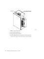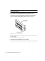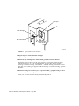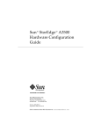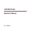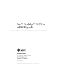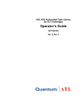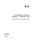
1
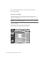
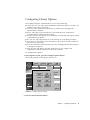
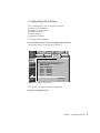
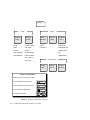
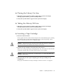
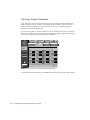
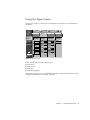
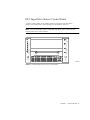
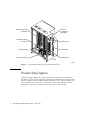
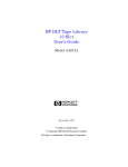
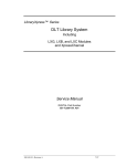
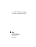
46 Sun StorEdge L1800 Operator’s Guide • May 1998 T tape cartridge inserting 21–22, 23 removing 23 unloading 23–25 tape drive 1, 2 front bezel 24 handle 24 tape drive status/control panel 1, 9–10 tape in use indicator 9, 10 tapes screen 17 troubleshooting status messages 38–39 typical problems 39 typographic conventions xii U unload button 9, 10, 24 unloading a drive 35 unloading a tape cartridge 23–25 unloading the load port 36 use cleaning tape indicator 9, 10 V vertical carriage 2 W write protect indicator 9, 10 Index 45 I P indicator operate handle 9, 10 Standby 7 tape in use 9, 10 use cleaning tape 9, 10 write protect 9, 10 inserting a tape cartridge 21–22, 23 interlock switch 7 inventory 33 power switch 8, 20 R receptacle, power 8 removing tape cartridges 23 S L light fixture 25–26 load port 1, 2, 6, 22 unloading 36 M main display control panel 3 SCSI address command 29–30 SCSI ID guidelines 30 structure 14 main display area 5 moving cartridges 32 N numbering conventions 10 O off-line 21 on-line 21 operate handle indicator 9, 10 operator screen 27 menu structure 28 overview screen 16 44 Sun StorEdge L1800 Operator’s Guide • May 1998 safety information xiii–xiv screens operator 27 overview 16 tapes 17 SCSI address, library 29, 30 SCSI interface 2 SCSI ports 8 SCSI-2 medium changer commands 2 shell prompts xii Standby button 7 Standby indicator 7 status display area 38 status messages 38 status/control panel, tape drive 1, 9–10 Stop button 7 Sun StorEdge L1800 Diagnostic Software User’s Manual xi, 8, 37 Sun StorEdge L1800 Facilities Planning and Installation Guide xi, 8 Sun StorEdge L1800 Field Service Manual xi, 7, 37 Sun StorEdge L1800 Software Interface Guide xi Sun StorEdge L1800 Unpacking Instructions xi Index A D AC power switch 8, 20 density select button 9 DIAG port 8 DLT7000 Cartridge Tape Drive Product Manual 9 DLT7000 tape drive 1, 11 drive, unloading 35 B back panel 8 bar code label 22 bezel, tape drive 24 button density select 9 Standby 7 Stop 7 unload 9, 10 C calibrating 34 cartridge handling mechanism 1, 2, 7 cartridges, moving 32 CHM 1, 7 CompacTape cartridges 11, 21 compatibility, tape cartridges 11, 21 configuring 29 options 31 control panel 1, 2, 3 navigation 15 conventions bin and drive numbering 10 typographic xii E exercising 34 F fixed storage array 1, 2, 41 front door 2, 7 H handle, tape drive 24 horizontal carriage 2 Index 43 FSE gripper assembly horizontal belt host host computer LCD Load Port The assembly that mounts on the extension axis and grips cartridges, referred to as the gripper. The drive belt connecting the horizontal motor to the horizontal axis assembly. Host computer The computer that issues SCSI commands to control the library robotics. Liquid crystal display The operator accessible component of the library that allows up to four cartridges to be import/export loaded and unloaded into/from the library. MTBF Mean time between failures MTTR Mean time to repair NVRAM Nonvolatile RAM off-line Not ready for communications with a host. This mode is required for configuration, diagnostic, and maintenance operations. on-line Ready for communications with a host. PC pick place PROM RAM rear panel SCSI tape drive UL vertical belt vertical carriage assembly 42 Field service engineer Personal computer The act of removing a cartridge from one location in preparation for placing it in another location. The act of placing a cartridge in a location after it has been picked from another location. Programmable read-only memory Random access memory The rear cosmetic panel of the library that contains the AC power switch, AC power receptacle and connectors for attaching external cabling to the library. Small computer system interface. A communications standard for attaching peripheral equipment to computers. The mechanism that reads and writes data from and to a tape cartridge. Underwriters Laboratories The drive belt connecting the vertical motor to the vertical axis assembly. The crossbar and linear bearings mounted on the vertical rails and all components mounted on the crossbar. Sun StorEdge L1800 Operator’s Guide • May 1998 Glossary actuators automated tape library bar code label bar code scanner calibration CHM DLT control panel EIA/TIA-574 extension axis assembly extension axis belt FCC Class A FSA Robotic components that move inside the library to manipulate cartridges. These include the cartridge handling mechanism, extension axis, vertical and horizontal axes. A robotic storage and retrieval system for DLT tape cartridges. The identification label on DLT tape cartridges. A device that is mounted on the extension axis that reads the cartridge bar code labels. The software measurements and configuration required for successful operation of the library. Cartridge handling mechanism Digital linear tape A touch-screen panel on the front of the library that contains a main display area as well as indicators and control buttons. A serial communications cabling and protocol standard for nine pin connectors, sometimes referred to as RS-232. The diagnostic port (DIAG), on the rear of the library, uses this protocol. Mounted onto the vertical axis, the extension axis assembly consists of the gripper assembly and the horizontal axis on which the gripper assembly is mounted. The drive belt connecting the extension motor/gearbox to the gripper. Standard established by the U.S. Federal Communications Commission governing electromagnetic emissions. Fixed storage array. This is a 3-column by 16-row fixture mounted inside the library. Its purpose is to store up to 48 cartridges in the library. Glossary 41 40 Sun StorEdge L1800 Operator’s Guide • May 1998 Troubleshooting Basic Problems TABLE 4-2 lists basic problems that you can troubleshoot as the operator. For problems not listed in this section, contact an authorized field service engineer. TABLE 4-2 Typical Problems with the Sun StorEdge L1800 Problem Resolution The library does not turn on. Make sure the power switch is in the | (on) position, all cables are connected, and the library has a unique SCSI ID number. If the library still does not turn on, contact an authorized field service engineer. A cable is disconnected from the back panel. Turn off the library, reconnect the cable as shown in Chapter 1, and turn on the library again. The library is off-line. Press the Standby button one time. If the library remains off-line, or if an error message appears on the display, contact an authorized field service engineer. The CHM does not move. First, visually inspect the CHM (through the front door window) for obstruction or restraint. If the Stop button was previously pressed, press the Stop button again to restore power to the CHM. If the CHM still does not move, contact an authorized field service engineer. A tape drive does not eject a tape cartridge. Use the manual unloading procedure found in Chapter 3. If the problem persists, contact an authorized field service engineer. A tape drive does not spin up. Make sure all cables are connected in the back panel and each tape drive has a unique SCSI ID number. If the drive still does not spin up, contact an authorized field service engineer. The host computer cannot communicate with the library. Make sure all cables are properly connected and that all SCSI devices (including the host computer and the library) have unique SCSI ID numbers. If the problem persists, contact an authorized field service engineer. Chapter 4 Operator Troubleshooting 39 System State Messages TABLE 4-1 lists the status messages which appear in the status display area of the control panel. TABLE 4-1 38 Status Message Descriptions Status Message Description/Action System Online The library is on-line and ready to communicate with the host computer. System Offline The library is off-line and ready to switch to menu mode or to accept commands from the diagnostic PC Going Online. . . Please Wait The library is switching from off-line to on-line but must complete the current command first. When finished, System Online appears in the display. Going Offline. . . Please Wait The library is switching from on-line to off-line but must complete the current command first. When finished, System Offline appears in the display. System Power-Up This is the first message displayed when the library is turned on. Initializing. . . Wait for Online This is the second message displayed when the library is turned on. This message is followed by the message System Online. Online Init Fail This message appears when initialization fails. System Stopped The STOP button has been pressed. System Door Open The library front door is open. Sun StorEdge L1800 Operator’s Guide • May 1998 CHAPTER 4 Operator Troubleshooting This chapter provides explanations of status messages which appear in the control panel display as well as actions necessary to correct specific problems. Note – The information in this chapter is limited to operator-level troubleshooting. For complete troubleshooting information, refer to the Sun StorEdge L1800 Diagnostic Software User’s Manual and the Sun StorEdge L1800 Field Service Manual. ■ ■ To Review Status Messages—page 38 To Troubleshoot Basic Problems—page 39 37 Unloading the Load Port This command moves a tape cartridge from the load port to an available storage bin. It must be invoked after inserting one or more tape cartridges into the load port whenever the library’s auto load feature is disabled. Note – You can also use the Move command (described earlier in this chapter) to unload the load port. The Move command is especially useful if the destination of the move needs to be specified. To unload the load port, press the Unload Imp/Exp button in the Operator screen. An “In Progress” dialog box appears. The dialog box remains on the screen until the move is completed, aborted by pressing the ABORT button, or stopped due to an error condition. 36 Sun StorEdge L1800 Operator’s Guide • May 1998 The exercise process runs continuously until you stop the process by pressing the ABORT button. The exercise process is also stopped if an error is detected. Unloading a Drive This command prepares a tape cartridge to be ejected from a drive by disengaging the tape from the read/write heads and rewinding it. After unloading the drive, you can eject and remove the tape cartridge using the Move Cartridge command described earlier in this chapter. To unload a drive: 1. In the Operator screen, press the Unload Drive button. The Unload Drive screen appears (FIGURE 3-11). Back Overview System Offline Standby Load Port Forward Tapes Home Operator Service Control: Unload Drive Drive 0 Drive 1 Drive 2 Drive 3 Drive: S _ Execute Stop FIGURE 3-11 Unload Drives Screen 2. Use the Left and Right Arrow buttons to select the desired tape drive. 3. Press the Execute button. This initiates the unload drive operation. An “In Progress” dialog box appears. The dialog box remains on the screen until the unload operation is completed, aborted by pressing the ABORT button, or stopped due to an error condition. Chapter 3 Operating Procedures 35 Calibrating the Library This command enables you to calibrate the storage bins, the tape drives, the load port, or the entire library. The library should be calibrated during initial installation and after any maintenance procedure. To calibrate library elements: 1. In the Operator page, press the Calibrate Library button. The Calibrate Library screen appears (FIGURE 3-10). Back Overview System Offline Standby Forward Tapes Home Operator Service Calibrate Library Calibrate All Calibrate Drives Calibrate Bins Load Port S Calibrate Load Port Stop FIGURE 3-10 Calibrate Library Screen 2. Press the button with the desired calibration option. This initiates the calibration command. An “In Progress” dialog box appears. The dialog box remains on the screen until the calibration is completed, aborted by pressing the ABORT button, or stopped due to an error condition. Exercising the Library This command tests library robotics and calibration by randomly moving tape cartridges from one element to another. To exercise library elements, press the Exercise Library button in the Operator screen. An “In Progress” dialog box appears. 34 Sun StorEdge L1800 Operator’s Guide • May 1998 2. Identify the source element (that is, the element with the tape cartridge to be moved). To do this: a. Press the appropriate element type button (Storage Bin, Tape Drive, Load Port, or Gripper). When you press an element type button, the range of addresses appears in the Range display. b. Using the keypad, enter the address for the source element The source information appears in the Source input field. c. When you have finished entering the address, press the Destination input field. The Destination input field becomes active. 3. Select a destination for the cartridge as follows: a. Press the appropriate element type button (Storage Bin, Tape Drive, Load Port, or Gripper). When you press an element type button, the range of addresses appears in the Range display. b. Using the keypad, enter the address for the destination element. The destination information appears in the Destination input field. c. When you have finished entering the address, press the Execute button. This initiates the move command from the source element to the destination element. An “In Progress” dialog box appears. The dialog box remains on the screen until the move is completed, aborted by pressing the Abort button, or stopped due to an error condition. Performing an Inventory This command identifies all tape cartridges in the library by bar code label and determines their location. Elements that are empty or that contain unlabeled cartridges are marked as such. To perform an inventory, press the Inventory Tapes button in the Operator screen. An “In Progress” screen appears. The dialog box remains on the screen until the inventory is completed, aborted by pressing the Abort button, or stopped due to an error condition. Chapter 3 Operating Procedures 33 3. Use the left and right scroll buttons to scroll to the new desired setting. 4. Press the Execute button. Moving Cartridges This command enables you to move any tape cartridge in the library to the destination element you specify. The destination can be a storage bin, a tape drive, the load port, or the gripper. Note – To move a cartridge from a tape drive, you must first issue an Unload Drive command as explained later in this chapter. To move a cartridge: 1. In the Operator screen, press the Move Cartridges button. The Control: Move Cartridges screen appears (FIGURE 3-9). Back Overview System Offline Standby Load Port Forward Tapes FIGURE 3-9 32 Operator Service 1 2 Storage Bin 3 4 Destination: Tape Drive 5 6 Range: Load Port 7 8 Gripper 9 0 Control: Move Cartridges Source: _ S Stop Home Execute Control: Move Cartridge Screen Sun StorEdge L1800 Operator’s Guide • May 1998 Select Configuring Library Options The Configure Options command allows you to set the following: ■ ■ ■ ■ ■ ■ ■ ■ Library power-up state. This option determines whether the library is on-line or in standby mode when powered up. Auto clean. This option allows the library to perform drive cleaning tasks automatically as needed. Retries. This option causes the library to automatically retry a failed move command before issuing an error message. Exabyte emulation. This option causes the library to return the same inquiry string as the Exabyte tape library. Bar code scan. This option turns bar code scanning on or off during inventory. Auto inventory. This option causes the library to perform an inventory whenever the library is powered up. Auto load. The library automatically moves any cartridge placed in the load port to an empty storage bin. Temp Detection. The library will shut off the motor power supply if the temperature inside the cabinet rises above 40˚C (104˚F). To configure these options: 1. In the Operator screen, press the Configure Options button. The Config.: Options screen appears (FIGURE 3-8). Back Overview System Offline Standby Load Port S Forward Tapes Home Operator Config.: Options Power-On State Auto Clean Retries Exabyte Emulation Barcode Labels Auto Inventory Auto Load Temp. Detection Current Value: _ New Value: _ Execute Stop FIGURE 3-8 Service Config.: Options Screen 2. Press the desired function button. Chapter 3 Operating Procedures 31 The Configure: Library Settings screen appears (FIGURE 3-7). Back Overview System Offline Standby Forward Tapes Home Operator Service Configure: Library Settings Model: _ # Bins: Load Port #Drives: Device: S SCSI ID: Execute Stop FIGURE 3-7 Select Configure: Library Settings Screen 3. Press the Select button to highlight the desired option. 4. Press the Left and Right Arrow buttons to scroll to the desired setting. 5. Press the Execute button to change to the new setting. 6. To return to the Operator screen, press the Back button two times. SCSI ID Assignment Guidelines When selecting SCSI IDs using this procedure, remember that each SCSI device on the same SCSI bus must have a unique ID number (from 0 to 15). SCSI devices include the library robotics, the host computer, the library tape drives, internal and external hard disk drives, and so on. If you set up the library with multiple SCSI busses, you can assign the same number to two or more devices provided each device is on a different SCSI bus. 30 Sun StorEdge L1800 Operator’s Guide • May 1998 Configuring the Library This command allows you to assign the following: ■ ■ ■ ■ ■ Library model number Number of storage bins Number of drives Library SCSI ID Tape drive SCSI IDs To configure these attributes: 1. In the operator screen, press the Configure Library button. The Config: Library screen appears (FIGURE 3-6). Back Overview System Offline Standby Load Port S Forward Tapes Operator Service Config.: Library Inquiry: ATL ACL 4/52 6210090 2.10 Model: 6210090 #Bins: 48 #Drives: 4 Library Drive 0 Drive 1 Drive 2 Drive 3 SCSI ID: 0 SCSI ID: 2 SCSI ID: 3 SCSI ID: 4 SCSI ID: 5 Configure Stop FIGURE 3-6 Home Config.: Library Screen The current configuration settings are displayed. 2. Press the Configure button. Chapter 3 Operating Procedures 29 Operator Config. Configure Library Control Configure Options Move Cartridges Inventory Tapes Calibrate Library Model Power-on State Source Calibrate All # Bins Auto Clean Destination Calibrate Drives # Drives Retries Calibrate Load Library SCSI ID Exabyte Emultn. Port Drive SCSI IDs Barcode Labels Calibrate Bins Auto Inventory Control (cont.) Auto Load Exercise Library Control Panel Navigation Select one of the menu tabs to start To move back screen by screen: Back To move forward screen by screen: Forward To go back to the Main Menu: Home To adjust the contrast: FIGURE 3-5 28 Operator Screen Menu Structure Sun StorEdge L1800 Operator’s Guide • May 1998 Unload Drives Unload Imp/Exp Using the Operator Screen The operator screen in the control panel contains library configuration and control functions. ▼ To Open the Operator Screen 1. Press the Operator tab in the main display area. A dialog box appears requesting a password 2. Using the keypad, enter the correct operator or service password and then press the Select button. The operator screen appears in the main display area (FIGURE 3-4). Back Overview System Offline Standby Config. Forward Tapes Home Operator Service Control Configure Drives Move Cartridges Calibrate Library Unload Drive Configure Library Inventory Tapes Exercise Library Unload Imp/Exp Load Port S Stop FIGURE 3-4 Operator Screen FIGURE 3-5 on page 28 gives an overview of the operator screen. Chapter 3 Operating Procedures 27 Light switch Interior light (attached to the ceiling of the library) TA00141a FIGURE 3-3 Internal Light Fixture 5. Close and latch the front door. 6. Press the Stop button to release it. 7. Press the Standby button and verify that the system goes on-line. “System Online” appears in the control panel’s system state display. 26 Sun StorEdge L1800 Operator’s Guide • May 1998 9. Pull the cartridge completely out of the drive. 10. Close the library door. 11. Press the Stop button to release it. 12. Press the Standby button and verify that the system goes on-line. “System Online” appears in the system state display. ▼ Turning On or Off the Interior Light Note – The library is normally shipped with the interior light turned on. The following procedure can be used to turn the light off or on. Note – The interior light bulb is not an operator-replaceable item. If the light bulb needs to be replaced, please notify an authorized field service engineer. 1. Press the Standby button and verify in the control panel’s system state display that the system goes off-line. 2. Press the Stop button. Caution – To prevent injury from moving components, always press the Stop button before opening the front door. 3. Open the front door by pulling it toward you. The door opens to the right. Note – The front door provides the only access to the internal light. 4. Reach through the front door and set the light switch located on the far side of the light (FIGURE 3-3). Chapter 3 Operating Procedures 25 Note – The front door provides the only access to the tape drives for manually unloading tape cartridges. 4. Locate the drive to be unloaded and press the Unload button (FIGURE 3-2). When you press Unload, the tape cartridge completely unwinds. Depending on the position of the tape, this may take between 10 and 120 seconds. After the tape rewinds, the Operator Handle indicator lights (see FIGURE 1-6 on page 9). DLT tape drive front bezel Unload button FIGURE 3-2 DLT Tape Drive Front Bezel 5. When the Operator Handle indicator lights, raise the insert/release handle to eject the tape cartridge. 6. Wait two seconds before going on to step 7. 7. Slowly pull the tape cartridge half way out of the drive. 8. If the tape cartridge leader is buckled to the take-up leader, push the cartridge all the way back into the drive and repeat steps 4–6. If the tape is clear, go to step 9. 24 Sun StorEdge L1800 Operator’s Guide • May 1998 ▼ Removing a Tape Cartridge 1. When one or more tape cartridges have been moved to the load port to be exported (as explained later in this chapter), press the Load Port button. It may require several seconds for the load port door to automatically open. A dialog box appears in the control panel with the message “Load Port Opening—Please Wait...” until the load port door is completely open. Caution – Mechanical hazards could be present while the load port is partially open. Do not insert your hand into the load port at any time. 2. When the load port opens completely, remove the tape cartridge(s) from the load port. Up to four tape cartridges can be removed at one time. 3. When all tape cartridges have been removed, press the Load Port button. When the load port door is in the open position, pressing the Load Port button unlocks the door so it can be closed manually. A dialog box appears with the message “Load Port Closing—Please Wait...” until the locking mechanism releases the door. Then a dialog box appears with the message “Load Port Closing—Operate Handle.” 4. When the dialog box instructs you to “operate handle,” grasp the load port door handle and push the load port door closed. After you close the door, the library automatically locks it. ▼ Manually Unloading a Tape Cartridge 1. Press the Standby button and verify that “System Offline” appears in the control panel’s system state display. 2. Press the Stop button. This button removes power from the CHM to prevent it from moving. Caution – To prevent injury from moving components, always press the STOP button before opening the front door. 3. Open the front door by pulling it toward you. The door opens to the right. Chapter 3 Operating Procedures 23 Load port Tape cartridge Bar code label (opens to right/ closes to left) TA00010c FIGURE 3-1 Tape Orientation for Insertion 4. Repeat step 3 to load additional cartridges. Up to four tape cartridges can be inserted at one time. 5. When all tape cartridges have been loaded, press the Load Port button. When the load port door is in the open position, pressing the Load Port button unlocks the door so it can be closed manually. A dialog box appears with the message “Load Port Closing—Please Wait...” until the locking mechanism releases the door. Then a dialog box appears with the message “Load Port Closing—Operate Handle.” 6. When the dialog box instructs you to “operate handle,” grasp the load port door handle and push the load port door closed. After you close the door, the library automatically locks it. 22 Sun StorEdge L1800 Operator’s Guide • May 1998 ▼ Placing the Library On-Line 1. With library power turned on and the control panel’s system state display showing “System Offline,” press the Standby button. 2. Verify that “System Online” appears in the system state display. ▼ Taking the Library Off-Line 1. With library power turned on and the control panel’s system state display showing “System Online,” press the Standby button. 2. Verify that “System Offline” appears in the system state display. ▼ Inserting a Tape Cartridge 1. Press the Load Port button. It may require several seconds for the load port door to automatically open. A dialog box appears in the control panel with the message “Load Port Opening—Please Wait...” until the load port door is completely open. Caution – Mechanical hazards could be present while the load port is partially open. Do not insert your hand into the load port at any time. 2. Examine the tape cartridge to be inserted into the load port. Make sure it is the proper type (CompacTape III or IV). Also make sure that its label is properly attached and no foreign material clings to the cartridge. Caution – Do not use CompacTape I, CompacTape II, or CompacTape IIIXT tape cartridges in this library. 3. When the load port door opens completely, place the tape cartridge in any available bin. The proper orientation for the tape cartridge is shown in FIGURE 3-1 on page 22. Chapter 3 Operating Procedures 21 Basic Procedures Basic operating procedures involve the use of physical switches and library controls to alter the library’s operation. Although the control panel screens are not used for these procedures, library controls in the vertical bar of the control panel and dialog boxes which appear in the main display area may be involved. This section contains procedures for the following: ■ ■ ■ ■ ■ ■ ▼ Turning the library on and off Placing the library on-line Taking the library off-line Inserting and removing tape cartridges using the load port Manually unloading a tape cartridge from a tape drive Turning the interior light on and off Turning On the Library 1. Verify that the front door and load port are closed, that all cosmetic panels are in place, and that all rear panel cables are securely connected. 2. At the back panel, set the AC power switch to the | (on) position. After several seconds, verify that the system state display of the control panel shows “System Online.” Note – In factory default configuration, the library goes on-line after being turned on. If you change the power-up state of the library, the system state display should indicate “System Offline” instead. ▼ Turning Off the Library 1. Press the control panel Stop button. 2. Press the control panel Standby button and make sure “System Offline” appears in the system state display of the control panel. 3. At the back panel, set the AC power switch to the O (off) position. 20 Sun StorEdge L1800 Operator’s Guide • May 1998 CHAPTER 3 Operating Procedures This chapter describes the following library operating procedures: ■ Basic Procedures ■ ■ ■ ■ ■ ■ To turn the library on and off—page 20. To place the library on-line or off-line—page 21. To insert and remove tape cartridges—page 21. To manually unload and remove a tape cartridge—page 23. To turn on and off the interior light—page 25. Operator Screen Procedures ■ ■ ■ ■ ■ ■ ■ ■ To configure the library—page 29. This procedure includes setting the library model number, the number of storage bins, the number of drives, the library SCSI ID and the drive SCSI IDs. To configure library options—page 31. This procedure allows you to configure the library’s power-on state, auto clean mode, retries option, Exabyte emulation, bar code label reading function, auto inventory operation, and auto loading at the load port. To move cartridges—page 32. To inventory the dataset—page 33. To calibrate the library—page 34. To exercise the library—page 34. To unload a drive—page 35. To unload the load port—page 36. 19 Viewing Screen Elements Some categories in the Overview and Tapes screens contain too many elements to display on the screen at one time. Up and down arrow buttons at the bottom of a category indicate that there are more elements to view. To scroll through these elements, touch the arrow buttons. You can also expand a category to fill the screen by touching the category anywhere above the scrolling arrows. For example, touching the storage category on the Tapes screen causes the screen expansion shown in FIGURE 2-4. Back Overview System Offline Forward Dataset Tapes Home Operator Service Storage Standby 000 ANF 099 004 ANF 103 008 ANF 107 012 ANF 111 Load Port 001 ANF 100 005 ANF 104 009 ANF 108 013 ANF 112 002 ANF 101 006 ANF 105 010 ANF 109 014 ANF 113 003 ANF 102 007 ANF 106 011 ANF 110 015 ANF 114 S Stop FIGURE 2-4 Tapes Screen with Expanded Storage Display To return the screen to normal, press the Back button at the top of the control panel. 18 Sun StorEdge L1800 Operator’s Guide • May 1998 Using the Tapes Screen As shown in FIGURE 2-3, the Tapes screen displays the inventory of all elements in the library. Back Overview System Offline Forward Dataset Tapes Tape Drives Storage Home Operator Service Load Port Transport Standby 00 EMPTY 000 ANF 099 P00 ANF 146 Load Port 01 EMPTY 001 ANF 100 P01 ANF 147 02 EMPTY 002 ANF 101 P02 ANF 148 03 EMPTY 003 ANF 102 P03 ANF 149 S GRP EMPTY Stop FIGURE 2-3 Tapes Screen In this screen, there are four element types: ■ ■ ■ ■ Tape drives Storage bins Load port Transport (gripper) Using these categories, you can determine whether a particular element has a tape cartridge and whether the cartridge is labeled. Chapter 2 Control Panel Functions 17 Basic Library Information You can obtain basic information about library configuration and operation using the Overview and the Tapes screens. Using the Overview Screen As shown in FIGURE 2-2, the Overview screen displays a snapshot of the following: ■ ■ ■ Tape drive status CHM activity Load port status Back Overview Overview System Offline Standby Forward Tapes Home Operator Service Tape Drive Status Activity Load Port D00 ANF 120 Ready D01 EMPTY Ready D01 EMPTY P00 ANF 146 D02 ??? Ready D03 ANF 123 Ready GRP EMPTY P01 ANF 147 Load Port S FIGURE 2-2 16 P03 ANF 149 002 ANF101 Stop Overview Screen Sun StorEdge L1800 Operator’s Guide • May 1998 P02 ANF 148 Control Panel Navigation The control panel uses a touch-screen for convenient navigation. To activate a command or open a screen, simply touch the appropriate “button” on the screen. You can also move backward and forward through screens opened previously by pressing the Back and Forward buttons. The Home button returns the control panel to the initial screen. Using Library Controls Library controls are located in the vertical bar on the left side of the control panel. They are always available, even when using the main display area to open operatoror service-related screens. To activate any of these controls, press the desired button. For a description of these functions, see Chapter 1. Opening a Screen To open one of the four main screens (Overview, Tapes, Operator, or Service), press the appropriate tab near the top of the control panel. The desired screen then appears in the main display area. Note – If you press either the Operator or Service tabs, a dialog box appears requesting a password. You must enter a password to display these screens. Once the desired screen appears, you can view information or press buttons to execute commands and open other screens. Exiting a Screen You can exit any screen by pressing the Back or Home buttons. If a command is executing, a dialog box appears in the main display area with an ABORT button. Pressing this button cancels the command and stops the ongoing operation. (Pressing the Back or Home button is still required to exit the screen associated with the dialog box.) Chapter 2 Control Panel Functions 15 Control Panel Structure As explained in Chapter 1, the control panel’s main display area consists of the following four screens: ■ ■ ■ ■ Overview Tapes Operator Service FIGURE 2-1 lists the structure of the control panel main display area. MAIN DISPLAY AREA Overview Tapes Tape Drive Status CHM Activity Load Port Tape Drives Storage Load Port Transport FIGURE 2-1 14 Menu Structure Sun StorEdge L1800 Operator’s Guide • May 1998 Operator Configure Library Configure Options Move Cartridges Inventory Dataset Calibrate Library Exercise Library Unload Drives Unload Imp/Exp Service Statistics Actuator Sys Test Results Sys Test Library Operate Axes Initialize Nonvol Stats Initialize Nonvol Config Change Password CHAPTER 2 Control Panel Functions As operator, your responsibilities may include using the control panel to check library status or to configure, calibrate, or test the library. This chapter describes basic menu structure and navigation and explains how to use the control panel to get status information and to perform basic functions. ■ ■ ■ ■ To To To To Understand the Menu Structure—page 14 Learn How to Navigate Through the Menu System—page 15 Use the Overview Screen—page 16 Use the Tapes Screen—page 17 Note – For advanced control panel functions, go to Chapter 4. Additional information about control panel operation is also available in the Sun StorEdge L1800 Diagnostic Software Manual and the Sun StorEdge L1800 Field Service Manual. 13 12 Sun StorEdge L1800 Operator’s Guide • May 1998 . Fixed storage array bins FIGURE 1-7 Bin 0 Bin 1 Bin 2 Bin 16 Bin 17 Bin 18 Bin 32 Bin 33 Bin 34 Bin 0 Bin 3 Bin 4 Bin 5 Bin 6 Bin 7 Bin 19 Bin 20 Bin 21 Bin 22 Bin 23 Bin 35 Bin 36 Bin 37 Bin 38 Bin 39 Bin 3 Bin 8 Bin 9 Bin 10 Bin 11 Bin 12 Bin 13 Bin 14 Bin 15 Bin 24 Bin 25 Bin 26 Bin 27 Bin 28 Bin 29 Bin 30 Bin 31 Bin 40 Bin 41 Bin 42 Bin 43 Bin 44 Bin 45 Bin 46 Bin 47 Bin 1 Load port bins Bin 2 Drive 0 Drive 1 DLT tape drives Drive 2 Drive 3 Bin and Drive Numbering Conventions Tape Cartridge Compatibility The library uses DLT7000 tape drives which support CompacTape III (dark gray) and CompacTape IV (black) tape cartridges. Caution – Do not use CompacTape I, II, or IIIXT tape cartridges in this library. Chapter 1 Library Overview 11 TABLE 1-1 DLT7000 Tape Drive Status/Control Panel Functions Feature Function Unload button This button is used to unload the tape from the drive to prepare it for ejecting and removal. When you press this button, the drive rewinds the tape and unloads the tape from the drive back into the cartridge. The tape cartridge must be completely rewound and unloaded before ejecting it from the drive. Depending on tape position, rewinding and unloading the tape may take from 10 to 120 seconds. Operate Handle indicator This green indicator lights when the insert/release handle is ready to operate. Use Cleaning Tape indicator This yellow indicator lights when the drive head needs cleaning or the current cleaning tape is bad. After unloading the cleaning tape cartridge, the indicator remains lit if the cleaning operation was not completed or if the cleaning tape was bad. Tape in Use indicator This yellow indicator flashes while the tape cartridge loads and becomes calibrated. After calibration, the indicator remains lit. Write Protect indicator This orange indicator lights when the loaded tape cartridge is write protected. Library Numbering Conventions FIGURE 1-7 shows the numbering conventions for storage bins, load port bins, and tape drives. These numbering conventions are used by the diagnostic software and the library menu system viewed in the status display area of the control panel when the library is off-line 10 Sun StorEdge L1800 Operator’s Guide • May 1998 DLT Tape Drive Status/Control Panel A status/control panel can be found on the front panel of each tape drive (FIGURE 1-6). The functions of this display are described in TABLE 1-1. Note – For a detailed description of the DLT tape drive, refer to the DLT7000 Cartridge Tape Drive Product Manual. 0 6. t e ec rit rot P W 6 2. ed .0 20 0 5. /1 .0 e pe us Ta In 10 s e ty d si rri en ve O D es pr om C e ng at le ni e lea pe per and Us C Ta O H .0 35 d ct oa le nl U Se TA00052b FIGURE 1-6 DLT7000 Tape Drive Status/Control Panel Chapter 1 Library Overview 9 Back Panel Figure 1-5 shows the back panel of the library. This panel contains the AC power switch and receptacle and various communication ports for the host computer, tape drives, and diagnostic PC. As the operator, you only need access to the back panel to turn the library on and off and to verify that cables are properly connected. Field service engineers use the back panel to set up the system and to use the diagnostic PC. For more information about setting up the system, refer to the Sun StorEdge L1800 Facilities Planning and Installation Guide. For more information about using the diagnostic PC and diagnostic software, refer to the Sun StorEdge L1800 Diagnostic Software User’s Manual. AC power receptacle and switch DIAG Spares (breakouts) SCSI Port 4 SCSI Port 3 SCSI Port 2 SCSI Port 1 FIGURE 1-5 8 Back Panel Sun StorEdge L1800 Operator’s Guide • May 1998 Front Door FIGURE 1-4 shows the library’s front door and interlock switch. You can use this door to access the DLT tape drives to manually eject and remove tape cartridges. Note – Field service engineers use the front door to perform various maintenance procedures. For more information, refer to the Sun StorEdge L1800 Field Service Manual. To ensure your safety, the interlock switch removes power from the CHM when the door is opened. Caution – To prevent injury from moving components, always set the library to off-line mode and stop the CHM before opening the front door. To do so, press the Standby button and wait until the system state display indicates that the system is off-line. Then press the Stop button to cut the power to the CHM. Front door (open) Handle Interlock switch FIGURE 1-4 Front Door Chapter 1 Library Overview 7 Load Port The load port (FIGURE 1-3) is located at the front of the library above the control panel. This port enables you to insert or remove up to four tape cartridges. The Load Port button on the control panel allows you to open and close the load port door. For more information about load port operation, see Chapter 3. Load port (open) Cartridge (closes to left) TA00010c FIGURE 1-3 6 Load Port Sun StorEdge L1800 Operator’s Guide • May 1998 Main Display Area The main display area consists of the following four screens: ■ ■ ■ ■ Overview. This screen displays a snapshot of the tape drives, CHM activity, and load port inventory. Tapes. This screen displays the contents of the tape drives, storage bins, load port, gripper, and pass-through mechanism (if supported). Operator. This screen contains the library configuration and control functions. To use this screen, you must have either operator or service security clearance. Service. This screen contains reporting functions, system tests, and miscellaneous commands. To use this screen, you must have service security clearance. For more information about the Overview and Tapes screens, see Chapter 2. For more information about the Operator screen, see Chapter 3. For more information about the Service screen, see the Sun StorEdge L1800 Diagnostic Software Manual and the Sun StorEdge L1800 Field Service Manual. Note – You must enter the correct password to access the Operator and Service screens. If you do not have the appropriate password, consult your system administrator. Chapter 1 Library Overview 5 Horizontal Bar The horizontal bar extends along the top of the control panel screen and consists of the following four controls: ■ ■ ■ ■ Back button. This button moves you backwards screen-by-screen through previous menu selections. Forward button. This button moves you forward screen-by-screen through previous menu selections. Home button. This button returns you to the initial control panel screen (shown in FIGURE 1-2). Contrast buttons. These buttons adjust the contrast of the screen. Vertical Bar The vertical bar extends along the left edge of the control panel screen and consists of the following controls and indicators: ■ ■ ■ ■ System state display. This display gives the current state of the library (on-line or off-line) and displays important messages relating to library operation. Standby button. This button switches the library between on-line and off-line mode. Load Port button. When the load port is closed, this button causes the load port door to open. When the load port is open, this button unlocks the load port door, allowing the door to be closed manually. Security Level indicator. This indicator gives the current security level available at the control panel. The following security levels are available: U (user), O (operator), and S (service). Note – For more information about security levels, see the “Main Display Area” section in this chapter and Chapters 2 and 3. ■ ■ 4 System activity indicator. This indicator, a dotted line directly below the security level indicator, flashes to show library activity. Stop button. This button halts all activity in the library by cutting power to the CHM. Pressing the Stop button a second time restores power to the CHM. Sun StorEdge L1800 Operator’s Guide • May 1998 As the operator, you need to be able to access the following library components: ■ ■ ■ ■ ■ Control panel Load port Front door Tape drive status/control panel Back panel These components are described in the following sections. Control Panel The control panel (FIGURE 1-2) is located at the front of the library to the right of the front door. Its features are described in this section. Horizontal bar Back Overview Forward Tapes Home Operator Service System Offline Standby Vertical bar Control panel Main display area Load Port S Stop FIGURE 1-2 Control Panel The control panel can be divided into three sections: ■ ■ ■ Horizontal bar Vertical bar Main display area Chapter 1 Library Overview 3 Fixed storage array (3x16 bins) Load port (4 additional cartridges) Cartridge handling mechanism Control panel Vertical carriage Door handle Horizontal carriage Tape drives (4) (Front) TA00038d FIGURE 1-1 Sun StorEdge L1800 (Left Cosmetic Panel Removed) Product Description The Sun StorEdge L1800 is the storage and retrieval component of an automated tape library system. A host computer communicates with the library through a SCSI interface using the SCSI-2 medium changer command set. In a typical operation, the host computer issues commands to the CHM to transfer tape cartridges between storage bins or between a storage bin and a tape drive or the load port. 2 Sun StorEdge L1800 Operator’s Guide • May 1998 CHAPTER 1 Library Overview This manual describes the Sun StorEdge L1800, shown in FIGURE 1-1. This library consists of the following main components: ■ A robotic handler, referred to as the cartridge handling mechanism (CHM) ■ Up to 48 digital linear tape (DLT) cartridges in a fixed storage array (FSA) ■ Up to four DLT7000 tape drives ■ A load port which can hold four additional cartridges ■ A control panel used to set options, check operating statistics, and diagnose errors ■ A tape drive status/control panel used to set drive options and check drive status This chapter gives a brief description of these and other library components. 1 Caution – Your Sun product is shipped with a grounding type (3-wire) power cord. To reduce the risk of electric shock, always plug the cord into a grounded power outlet. Panels and Cover Caution – It is not safe to operate Sun products without the panels and covers in place. Failure to take this precaution may result in personal injury and system damage. Preface xv Caution – Hazardous voltages are present. To reduce the risk of electric shock and danger to personal health, follow the instructions. Hot Surface – Hot surface or materials are present. To reduce the risk of burns, follow the instructions. Modification to Equipment Do not make mechanical or electrical modifications to the equipment. Sun Microsystems, Inc. is not responsible for regulatory compliance of a modified Sun product. Placement of a Sun Product Caution – To ensure reliable operation of your Sun product and to protect it from overheating, openings in the equipment must not be blocked or covered. A Sun product should never be placed near a radiator or heat register. Power Cord Connection Caution – Sun products are designed to work with single-phase power systems that have a grounded neutral conductor. To reduce the risk of electric shock, do not plug Sun products into any other type of power system. Contact your facilities manager or a qualified electrician if you are not sure what type of power is supplied to your building. Caution – Not all power cords have the same current ratings. Household extension cords do not have overload protection and are not meant for use with computer systems. Do not use household extension cords. xiv Sun StorEdge L1800 Operator’s Guide • May 1998 TABLE P-2 Shell Prompts Shell Prompt C shell superuser prompt machine_name# Bourne shell and Korn shell prompt $ Bourne shell and Korn shell superuser prompt # Safety Agency Compliance Before beginning any procedure, read the instructions and cautions in this section. They explain how to work safely with the internal components of your system. The equivalent information, translated into French, German, and Spanish, can be found at the beginning of this document. Safety Precautions For your protection, observe the following safety precautions when setting up your equipment: ■ Follow all warnings and instructions marked on the equipment. ■ Ensure that the voltage and frequency of your power source matches the voltage and frequency inscribed on the equipment’s electrical rating label. ■ Never push objects of any kind through openings in the equipment. Dangerous voltages may be present. Conductive foreign objects could produce a short circuit that could cause fire, electric shock, or damage to your equipment. Symbols The following symbols appear in this book: Caution – Risk of personal injury and equipment damage. Follow the instructions. Preface xiii What Typographic Changes Mean The following table describes the typographic changes used in this book. TABLE P-1 Typographic Conventions Typeface or Symbol Meaning Example AaBbCc123 The names of commands, files, and directories; on-screen computer output Edit your .login file. Use ls -a to list all files. machine_name% You have mail. AaBbCc123 What you type, contrasted with on-screen computer output AaBbCc123 Command-line placeholder; replace with a real name or value To delete a file, type rm filename. AaBbCc123 Book titles, new words or terms, or words to be emphasized Read Chapter 6 in User’s Guide. These are called class options. You must be root to do this. machine_name% su Password: Shell Prompts in Command Examples The following table shows the default system prompt and superuser prompt for the C shell, Bourne shell, and Korn shell. TABLE P-2 xii Shell Prompts Shell Prompt C shell prompt machine_name% Sun StorEdge L1800 Operator’s Guide • May 1998 Preface This book explains how to operate the Sun™ StorEdge™ L1800. It assumes that the library has already been unpacked and installed using instructions found in the Sun StorEdge L1800 Unpacking Instructions and the Sun StorEdge L1800 Facilities Planning and Installation Guide. First read the “Safety Agency Compliance” section at the end of this preface. Then refer to the specific chapters to find the information you need. Who Should Use This Book This book is designed to aid nontechnical users in the operation of the tape library system. It begins with a general description of library components and continues with detailed descriptions of control panel menu functions and specific operating procedures. It also contains basic troubleshooting information. This book does not address highly technical issues and procedures, such as hardware maintenance, diagnostic software operation, or library software development. To obtain this information, authorized field service engineers and system programmers should refer to the following documents: ■ Sun StorEdge L1800 Diagnostic Software User’s Manual ■ Sun StorEdge L1800 Field Service Manual ■ Sun StorEdge L1800 Software Interface Guide xi x Sun StorEdge L1800 Operator’s Guide • May 1998 Tables TABLE P-1 TABLE P-2 Typographic Conventions xii Shell Prompts xii TABLE 1-1 DLT7000 Tape Drive Status/Control Panel Functions TABLE 4-1 Status Message Descriptions 38 TABLE 4-2 Typical Problems with the Sun StorEdge L1800 10 39 Tables ix viii FIGURE 3-9 Control: Move Cartridge Screen 32 FIGURE 3-10 Calibrate Library Screen FIGURE 3-11 Unload Drives Screen 35 34 Sun StorEdge L1800 Operator’s Guide • May 1998 Figures FIGURE 1-1 Sun StorEdge L1800 (Left Cosmetic Panel Removed) FIGURE 1-2 Control Panel 3 FIGURE 1-3 Load Port 6 FIGURE 1-4 Front Door 7 FIGURE 1-5 Back Panel 8 FIGURE 1-6 DLT7000 Tape Drive Status/Control Panel 9 FIGURE 1-7 Bin and Drive Numbering Conventions 11 FIGURE 2-1 Menu Structure 14 FIGURE 2-2 Overview Screen FIGURE 2-3 Tapes Screen 17 FIGURE 2-4 Tapes Screen with Expanded Storage Display 18 FIGURE 3-1 Tape Orientation for Insertion 22 FIGURE 3-2 DLT Tape Drive Front Bezel 24 FIGURE 3-3 Internal Light Fixture FIGURE 3-4 Operator Screen FIGURE 3-5 Operator Screen Menu Structure 28 FIGURE 3-6 Config.: Library Screen 29 FIGURE 3-7 Configure: Library Settings Screen FIGURE 3-8 Config.: Options Screen 31 2 16 26 27 30 Figures vii vi Sun StorEdge L1800 Operator’s Guide • May 1998 Using the Operator Screen ▼ 27 To Open the Operator Screen Configuring the Library 27 29 SCSI ID Assignment Guidelines Configuring Library Options Moving Cartridges Calibrating the Library Exercising the Library 33 34 34 35 Unloading the Load Port 4. Operator Troubleshooting System State Messages 36 37 38 Troubleshooting Basic Problems Glossary 31 32 Performing an Inventory Unloading a Drive 30 39 41 Contents v Load Port 6 Front Door 7 Back Panel 8 DLT Tape Drive Status/Control Panel Library Numbering Conventions Tape Cartridge Compatibility 2. Control Panel Functions 11 14 Control Panel Navigation 15 Using Library Controls Exiting a Screen 15 15 15 Basic Library Information 16 Using the Overview Screen Using the Tapes Screen Operating Procedures Basic Procedures iv 16 17 Viewing Screen Elements 3. 10 13 Control Panel Structure Opening a Screen 9 18 19 20 ▼ Turning On the Library 20 ▼ Turning Off the Library 20 ▼ Placing the Library On-Line 21 ▼ Taking the Library Off-Line 21 ▼ Inserting a Tape Cartridge ▼ Removing a Tape Cartridge ▼ Manually Unloading a Tape Cartridge ▼ Turning On or Off the Interior Light Sun StorEdge L1800 Operator’s Guide • May 1998 21 23 23 25 Contents Preface xi Who Should Use This Book xi What Typographic Changes Mean xii Shell Prompts in Command Examples Safety Agency Compliance Safety Precautions Symbols xiii xiii xiii Modification to Equipment xiv Placement of a Sun Product xiv Power Cord Connection Panels and Cover 1. xii Library Overview xiv 1 Product Description Control Panel xiv 2 3 Horizontal Bar Vertical Bar 4 4 Main Display Area 5 Contents iii Copyright 1998 Sun Microsystems, Inc., 901 San Antonio Road • Palo Alto, CA 94303 USA. All rights reserved. This product or document is protected by copyright and distributed under licenses restricting its use, copying, distribution, and decompilation. No part of this product or document may be reproduced in any form by any means without prior written authorization of Sun and its licensors, if any. Third-party software, including font technology, is copyrighted and licensed from Sun suppliers. Parts of the product may be derived from Berkeley BSD systems, licensed from the University of California. UNIX is a registered trademark in the U.S. and other countries, exclusively licensed through X/Open Company, Ltd. Sun, Sun Microsystems, the Sun logo, AnswerBook, SunDocs, StorEdge, and Solaris are trademarks, registered trademarks, or service marks of Sun Microsystems, Inc. in the U.S. and other countries. All SPARC trademarks are used under license and are trademarks or registered trademarks of SPARC International, Inc. in the U.S. and other countries. Products bearing SPARC trademarks are based upon an architecture developed by Sun Microsystems, Inc. The OPEN LOOK and Sun™ Graphical User Interface was developed by Sun Microsystems, Inc. for its users and licensees. Sun acknowledges the pioneering efforts of Xerox in researching and developing the concept of visual or graphical user interfaces for the computer industry. Sun holds a non-exclusive license from Xerox to the Xerox Graphical User Interface, which license also covers Sun’s licensees who implement OPEN LOOK GUIs and otherwise comply with Sun’s written license agreements. RESTRICTED RIGHTS: Use, duplication, or disclosure by the U.S. Government is subject to restrictions of FAR 52.227-14(g)(2)(6/87) and FAR 52.227-19(6/87), or DFAR 252.227-7015(b)(6/95) and DFAR 227.7202-3(a). DOCUMENTATION IS PROVIDED “AS IS” AND ALL EXPRESS OR IMPLIED CONDITIONS, REPRESENTATIONS AND WARRANTIES, INCLUDING ANY IMPLIED WARRANTY OF MERCHANTABILITY, FITNESS FOR A PARTICULAR PURPOSE OR NONINFRINGEMENT, ARE DISCLAIMED, EXCEPT TO THE EXTENT THAT SUCH DISCLAIMERS ARE HELD TO BE LEGALLY INVALID. Copyright 1998 Sun Microsystems, Inc., 901 San Antonio Road • Palo Alto, CA 94303 États-Unis. Tous droits réservés. Ce produit ou document est protégé par un copyright et distribué avec des licences qui en restreignent l’utilisation, la copie, la distribution, et la décompilation. Aucune partie de ce produit ou document ne peut être reproduite sous aucune forme, par quelque moyen que ce soit, sans l’autorisation préalable et écrite de Sun et de ses bailleurs de licence, s’il y en a. Le logiciel détenu par des tiers, et qui comprend la technologie relative aux polices de caractères, est protégé par un copyright et licencié par des fournisseurs de Sun. Des parties de ce produit pourront être dérivées des systèmes Berkeley BSD licenciés par l’Université de Californie. UNIX est une marque déposée aux États-Unis et dans d’autres pays et licenciée exclusivement par X/Open Company, Ltd. Sun, Sun Microsystems, le logo Sun, AnswerBook, SunDocs, StorEdge, et Solaris sont des marques de fabrique ou des marques déposées, ou marques de service, de Sun Microsystems, Inc. aux États-Unis et dans d’autres pays. Toutes les marques SPARC sont utilisées sous licence et sont des marques de fabrique ou des marques déposées de SPARC International, Inc. aux États-Unis et dans d’autres pays. Les produits portant les marques SPARC sont basés sur une architecture développée par Sun Microsystems, Inc. L’interface d’utilisation graphique OPEN LOOK et Sun™ a été développée par Sun Microsystems, Inc. pour ses utilisateurs et licenciés. Sun reconnaît les efforts de pionniers de Xerox pour la recherche et le développement du concept des interfaces d’utilisation visuelle ou graphique pour l’industrie de l’informatique. Sun détient une licence non exclusive de Xerox sur l’interface d’utilisation graphique Xerox, cette licence couvrant également les licenciés de Sun qui mettent en place l’interface d’utilisation graphique OPEN LOOK et qui en outre se conforment aux licences écrites de Sun. CETTE PUBLICATION EST FOURNIE “EN L’ÉTAT” ET AUCUNE GARANTIE, EXPRESSE OU IMPLICITE, N’EST ACCORDEE, Y COMPRIS DES GARANTIES CONCERNANT LA VALEUR MARCHANDE, L’APTITUDE DE LA PUBLICATION A REPONDRE A UNE UTILISATION PARTICULIERE, OU LE FAIT QU’ELLE NE SOIT PAS CONTREFAISANTE DE PRODUIT DE TIERS. CE DENI DE GARANTIE NE S’APPLIQUERAIT PAS, DANS LA MESURE OU IL SERAIT TENU JURIDIQUEMENT NUL ET NON AVENU. Sun™ StorEdge™ L1800 Operator’s Guide Sun Microsystems Computer Company A Sun Microsystems, Inc. Business 901 San Antonio Road Palo Alto, CA 94303-4900 USA 1 650 960-1300 fax 1 650 969-9131 Part No. 805-5575-10 Revision A, May 1998 Send comments about this document to: [email protected]