1
BNS-2000
Node Reference
255-184-153
Issue 1
Release 5.0
Copyright 1998 Lucent Technologies
All Rights Reserved
Printed in USA
CommKit, Datakit, DATAPHONE, DEFINITY, 5ESS, StarKeeper, are registered trademarks of Lucent Technologies.
UNIX is a registered trademark in the United States and other countries licensed exclusively through X/Open Company,
Ltd.
The information in this document is subject to change without notice.
Lucent Technologies assumes no responsibility for any errors that
may appear in this document.
________________
Contents
Preface
Important Notice
Year 2000 Compliance
Document Organization
Document Conventions
Related Documentation
Technical Assistance and Node Registration
Calling a Telephone Hotline
Escalation Procedure
Registering the Node
Node Overview
xxiii
xxiii
xxvi
xxvi
1-1
1-4
1-35
Physical Description
Node Features
Node Installation
Node
Node
Node
Node
Node
Node
xvii
xvii
xviii
xviii
xx
xxi
Configurations
Hardware Installation Checklists
Installation Preparation
Assembly
Module and I/O Board Installation
Administrative Interface Cabling
Node Operations
Power Up and Power Down
Software Installation and Start-up Procedures
Backing Up the Node Configuration Database
Retrieving the Node Configuration Database
Copying Disk Partitions and File Systems
Rebooting the Active Control Computer
Rebooting the Standby Control Computer
Restoring the Standby Switch
Formatting Disks and Tapes
BNS-2000 Node Reference, Release 5.0, Issue 1
2-1
2-3
2-7
2-13
2-14
2-39
2-95
3-1
3-5
3-9
3-29
3-31
3-32
3-34
3-39
3-41
3-42
iii
________________
Node Administration
Node Administration Tasks
Command Sets and Relationships
Configuring the Database
Routine Database Administration
Monitoring the Node
Obtaining On-line Reports
Checking the File System and Disk Storage
Database Resizing
Node Maintenance
Handling and Environment Guidelines
Preventive Maintenance
Node Troubleshooting
Problem Indicators
Diagnostics
Data Gathering Guidelines
Problem Areas
Node Hardware and Software Upgrades
Planning Notes
About the Upgrade Procedures
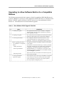
Upgrading to a New Software Build or to a Compatible Release
Backing Out of a Software Build Upgrade
Upgrading to a New Release—General Method
Upgrading to a New Release with Minimal Downtime
Appendix. Node Database Entry Forms
Index
iv
4-1
4-3
4-7
4-11
4-35
4-38
4-41
4-45
4-47
5-1
5-3
5-7
6-3
6-1
6-18
6-36
6-40
7-1
7-3
7-5
7-7
7-21
7-23
7-112
A-1
I-1
BNS-2000 Node Reference, Release 5.0, Issue 1
________________
Figures
1.
2.
3.
4.
5.
6.
Node ID Number on Control Computer Module (CCM)
Node ID Number on SCSI/DKI Module in an ECPU System
BNS-2000 Software Registration Notice Card
BNS-2000 Sample Feature Card with Activation ID
BNS-2000 VCS Software Registration Notice Card
BNS-2000 VCS Sample Feature Card with Activation Identifier
1-1.
1-2.
1-3.
1-4.
1-5.
1-6.
1-7.
1-8.
1-9.
1-10.
1-11.
1-12.
1-13.
1-14.
1-15.
1-16.
1-17.
1-18.
1-19.
BNS-2000 Standard Star Architecture Example
BNS-2000 Extended Star Architecture Example
BNS-2000 VCS Bus Architecture
BNS-2000 Series M2 Switch Shelf
BNS-2000 Series M2 Extension Shelf
BNS-2000 Series M1 Control Shelf
BNS-2000 VCS Series M1 Control Shelf
BNS-2000 VCS ECPU System Series M1 Control Shelf
BNS-2000 VCS ECPU System Control Cabinet
BNS-2000 Series M1 Port Shelf
BNS-2000 VCS Series M1 Port Shelf
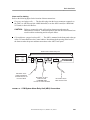
Administrative Configuration Example
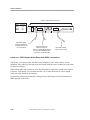
Remote Console and Printer Interfaces
Single Control Computer Configuration Example for a CCM System
Single Control Computer Configuration Example for an ECPU System
Disk Layout Example for a Single Control Computer Configuration
Dual Control Computer Configuration Example for a CCM System
Dual Control Computer Configuration Example for an ECPU System
Disk Layout Example for a Dual Control Computer Configuration
1-5
1-6
1-7
1-9
1-11
1-12
1-12
1-16
1-17
1-19
1-19
1-22
1-23
1-30
1-31
1-32
1-33
1-33
1-35
2-1.
2-2.
2-3.
2-4.
2-5.
2-6.
2-7.
2-8.
2-9.
2-10.
2-11.
Securing the Base Power Unit to Floor
Shelves With Base Power Unit: Stacked and Secured
Power Wiring for a Stack
Terminal Block and Grounding Connections
Inserting the Power Entry Module
Wiring the Power Entry Module
CO Frame Front and Rear Views
CO Frame Covers
Moving the CO Frame
Securing the CO Frame
Attaching Shelf Brackets
2-17
2-20
2-21
2-22
2-24
2-25
2-27
2-28
2-30
2-31
2-33
BNS-2000 Node Reference, Release 5.0, Issue 1
xxviii
xxix
xxx
xxxi
xxxii
xxxiii
v
________________
2-12.
2-13.
2-14.
2-15.
2-16.
2-17.
2-18.
2-19.
2-20.
2-21.
2-22.
2-23.
2-24.
2-25.
2-26.
2-27.
2-28.
2-29.
2-30.
2-31.
2-32.
2-33.
2-34.
2-35.
2-36.
2-37.
2-38.
2-39.
2-40.
2-41.
2-42.
3-1.
3-2.
3-3.
vi
CO Frame Fuse Diagram
Power Wiring in the CO Frame
Use of ESD Wrist Strap
Sample I/O Board With Switches
ASP1 I/O Board
CMC3 I/O Board Jumpers
Disk/Tape Drive Terminating Resistors on an ECPU System
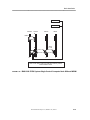
Series M2 Switch Shelf Cabling Rear View (One to Three Series M2
Extension Shelf Configuration)
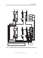
Series M2 Switch Shelf Cabling Rear View (Three to Five Series M2
Extension Shelf Configuration)
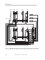
CCM System Single Control Computer Node Without MRCIO
CCM System Single Control Computer Node With MRCIO
CCM System Dual Control Computer Node in Single Cabinet
CCM System Dual Control Computer Node in Dual Cabinets
BNS-2000 and BNS-2000 VCS ECPU System Single Control
Computer Node With MRCM
BNS-2000 ECPU System Single Control Computer Node Without
MRCM
BNS-2000 VCS ECPU System Single Control Computer Node
Without MRCM
BNS-2000 ECPU System Dual Control Computer Node in Dual
Shelves
BNS-2000 VCS ECPU System Dual Control Computer Node in Dual
Shelves
ASP1 I/O Board Bus and Clock Cabling for BNS-2000 VCS Nodes
CCM System Alarm Relay Unit (ARU) Connections
ECPU System Alarm Relay Unit (ARU) Connections
Clock, Repeater, and Switch Modules Location in BNS-2000 VCS
Node
Sample Series M1 and M2 Module Faceplates
CCM Faceplate
I/O Cable Management Side Views
CCM System Console Cabling
ECPU System Console Cabling
CCM System Administrative Printer and ARU Cabling
ECPU System Administrative Printer and ARU Cabling
Cabling a CCM System Node to a StarKeeper II NMS Host
Cabling an ECPU System Node to a StarKeeper II NMS Host
BNS-2000 ECPU 40MB Tape Drive
BNS-2000 VCS ECPU System 40MB Tape Drive
CCM System Internal View of DDS Tape Drive
BNS-2000 Node Reference, Release 5.0, Issue 1
2-34
2-36
2-40
2-44
2-45
2-53
2-55
2-58
2-60
2-66
2-67
2-68
2-70
2-69
2-75
2-76
2-77
2-78
2-80
2-81
2-82
2-84
2-86
2-88
2-96
2-99
2-100
2-103
2-104
2-106
2-107
3-12
3-12
3-13
________________
3-4. CCM System External View of DDS Tape Drive
5-1. 40MB Tape Cartridge for ECPU System Tape Drive
5-2. CCM System DDS Tape Drive (Internal/External)
3-14
5-5
5-5
6-1.
6-2.
6-3.
6-4.
6-5.
6-6.
Loopback Connector for Use With a Modular Jack
Loopback Connector for Use at a 110 Patch Panel
Rear View of Voltage Check Points for Series M1 Power Supply Slots
Terminal Pin Assignments for Module Slots in Series M1 Shelves
Checking and Changing a Series M2 Shelf Fuse
Series M1 Shelf Fuses: Normal and Blown
6-30
6-31
6-47
6-48
6-50
6-52
7-1.
7-2.
7-3.
7-4.
7-5.
BNS-2000 Single CCM System Without MRCIO
BNS-2000 Single CCM System With MRCIO
BNS-2000 Dual CCM System With MRCIO (CCMs in Same Shelf)
BNS-2000 Dual CCM System With MRCIO
BNS-2000 Single Control Computer and Single Disk/Tape Slot
Assignments (ECPU)
BNS-2000 Dual Control Computers and Dual Disks/Tapes With
MRCM Slot Assignments (ECPU)
Back View of the CNA7 I/O Board
Modular Cabinet Slot Assignments: Datakit II VCS Release 6.0
Single CCM System Without MRCIO
Modular Cabinet Slot Assignments: Datakit II VCS Release 6.0
Single CCM System With MRCIO
Modular Cabinet Slot Assignments: Datakit II VCS Release 6.0 Dual
CCM System With MRCIO (CCMs in Same Shelf)
Modular Cabinet Slot Assignments: Datakit II VCS Release 6.0 Dual
CCM System With MRCIO
Terminating Resistors on Datakit II VCS ECPU System Disk Drive
Modular Cabinet Slot Assignments: Datakit II VCS Release 6.0
ECPU System Single Control Computer
Modular Cabinet Slot Assignments: Datakit II VCS Release 6.0
ECPU System Dual Control Computers
Model 2000 Slot Assignments: Datakit II VCS Release 6.0 ECPU
System Single Control Computer
Model 2000 Slot Assignments: Datakit II VCS Release 6.0 ECPU
System Dual Control Computers
7-39
7-40
7-40
7-41
7-6.
7-7.
7-8.
7-9.
7-10.
7-11.
7-12.
7-13.
7-14.
7-15.
7-16.
BNS-2000 Node Reference, Release 5.0, Issue 1
7-44
7-45
7-51
7-63
7-63
7-64
7-65
7-68
7-69
7-70
7-73
7-74
vii
________________
Tables
1-1.
1-2.
1-3.
1-4.
1-5.
1-6.
Administrative Interfaces: Ports A and B
BNS-2000 Series M2 Shelf and Slot Numbers
BNS-2000 Series M2 Shelf and Slot Module Assignments
Series M1 Shelf and Slot Numbers
BNS-2000 Series M1 Shelf Slot Assignments
BNS-2000 VCS Series M1 Slot Assignments
2-1. BNS-2000 and BNS-2000 VCS Hardware Configurations
2-2. CP Node Hardware Configurations
2-3. CO Node Hardware Configurations
2-4. CCM System Control Complex Configurations
2-5. ECPU System Control Complex Configurations
2-6. Hardware Installation Checklist for BNS-2000 CP Node With Base
Power Unit
2-7. Hardware Installation Checklist for BNS-2000 Node in a CO Frame
2-8. Hardware Installation Checklist for BNS-2000 VCS CP Node With
Base Power Unit
2-9. Hardware Installation Checklist for BNS-2000 VCS Node in a CO
Frame
2-10. Hardware Installation Tools Checklist
2-11. AC Power Service Combinations
2-12. DC Power Service Combinations
2-13. CCM System Critical Modules and Corresponding I/O Boards
2-14. ECPU System Modules and Corresponding I/O Boards
2-15. ASP1 Switch 1 Settings
2-16. ASP1 Switch 2 Settings
2-17. ASP1 Switch 3 Settings for a Single Cabinet Node
2-18. ASP1 Switch 3 Settings for a Multi-cabinet Node
2-19. ASP4B Switch Settings
2-20. ASP7B Switch Settings
2-21. AWJ15 Switch Settings
2-22. CMC2 Switch Settings
2-23. CMC3 Switch Settings
2-24. CMC3 Jumper Settings
2-25. CNA1 Switch Settings
viii
BNS-2000 Node Reference, Release 5.0, Issue 1
1-22
1-24
1-25
1-26
1-27
1-28
2-4
2-5
2-5
2-6
2-7
2-8
2-10
2-11
2-12
2-14
2-18
2-29
2-41
2-43
2-46
2-46
2-47
2-47
2-48
2-49
2-50
2-51
2-51
2-52
2-54
________________
2-26. CUW1 RIB Switch Settings
2-27. TN2096 Switch Settings
2-28. Series M2 Extension Shelf Cabling for a Standard Switch
Configuration
2-29. Series M2 Extension Shelf Cabling for an Extended Switch
Configuration
2-30. CCM System Single Control Computer (Without MRCIO) Node
Cabling
2-31. CCM System Single Control Computer (With MRCIO) Node Cabling
2-32. CCM System Dual Control Computer Node Cabling
2-33. ECPU System Single Control Computer Node Cabling Without
MRCM
2-34. ECPU System Single Control Computer Node Cabling With MRCM
2-35. BNS-2000 VCS ECPU System Dual Control Computer Node Cabling
With MRCM
2-36. BNS-2000 ECPU System Dual Control Computer Node Cabling With
MRCM
2-37. Printer Control Characters Ignored
2-38. Additional Printer Control Characters Ignored When ARU Is Present
2-39. Laser Printer Connections Through Null Modem Cable
2-54
2-54
2-57
2-59
2-64
2-65
2-65
2-70
2-71
2-72
2-73
2-101
2-102
2-102
3-1.
3-2.
3-3.
Command Sets, Modes, and Prompts
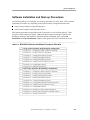
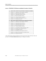
BNS-2000 Software Installation Procedures Checklist
BNS-2000 VCS Software Installation Procedures Checklist
3-3
3-9
3-10
4-1.
4-2.
4-3.
4-4.
4-5.
4-6.
4-7.
Command Relationships
Pattern Matching for Administrative Commands
Configuring the Database Checklist
Commands That Affect Control Computer Output
Commands That Direct MRC Output
Commands That Affect MRC Messages
Availability of Measurement Reports
4-8
4-10
4-11
4-38
4-40
4-41
4-44
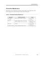
5-1.
Scheduled Hardware Maintenance
BNS-2000 Node Reference, Release 5.0, Issue 1
5-7
ix
________________
6-1.
6-2.
6-3.
6-4.
6-5.
6-6.
6-7.
6-8.
6-9.
6-10.
6-11.
6-12.
6-13.
6-14.
6-15.
6-16.
6-17.
6-18.
6-19.
6-20.
6-21.
6-22.
6-23.
6-24.
6-25.
6-26.
6-27.
6-28.
6-29.
6-30.
6-31.
6-32.
6-33.
6-34.
6-35.
6-36.
6-37.
x
Alarm Message Types
Priority-of-Action Codes for Alarms
CCM LEDs
CIM/CTRM LEDs
Clock LEDs
CMA1 Switch LEDs
CTG13 Switch LEDs
CSD9 LEDs
Disk or Tape Drive LEDs
ECPU LEDs
Eswitch LEDs
External Tape Drive LEDs
GAR LEDs
Internal Tape Drive LEDs
MRCIO LEDs
MRCM LEDs
Repeater LEDs
RIB LEDs
SCSI/DKI LEDs
Power Supply LEDs
LEDS on Interface Modules Residing in the Node, SAMs, and MPCs
LEDs on Interface Modules Residing in ISN Concentrators
Monitor Mode Diagnostics
Loader Mode Diagnostics for the CCM System
Loader Mode Diagnostics for the ECPU System
Critical Module Loader Mode Diagnostics for the CCM and ECPU
Systems
Troubleshooting Data Procedures Checklist
Problem Areas and Related Symptoms Checklist
Power: General Problems Checklist
Voltage Range and Measurement Points for Series M1 Shelf Power
Supply Slots
Control Computer: General Problems Checklist
Control Computer: Disk and Tape Problems Checklist
Dual Control Computer and MRC Problems Checklist
Switching, Clocking, CIM, and CTRM Problems Checklist
GAR: General Problems Checklist
End User: General Problems Checklist
End User: Modem Pool Problems Checklist
BNS-2000 Node Reference, Release 5.0, Issue 1
6-4
6-6
6-8
6-8
6-9
6-9
6-10
6-10
6-11
6-11
6-11
6-12
6-12
6-13
6-13
6-14
6-14
6-15
6-15
6-16
6-16
6-17
6-20
6-23
6-24
6-25
6-36
6-41
6-44
6-46
6-53
6-57
6-62
6-78
6-82
6-83
6-85
________________
7-1.
7-2.
7-3.
7-4.
7-5.
7-6.
7-7.
7-8.
7-9.
7-10.
7-11.
7-12.
7-13.
New Software Build Upgrade Checklist
Timing the Software Build Upgrade
New Release Upgrade–General Method Checklist
Upgrade Equipment Checklist
Timing the Upgrade
BNS-2000 Control Computer Hardware
BNS-2000 Series M2 Switch and Stratum 4 Clocking Complexes for
CCM or ECPU Systems
BNS-2000 Standard Switch Complex with Modules and I/O Boards
Removed
BNS-2000 Extended Switch Complex with Modules and I/O Boards
Installed
Datakit II VCS Control Computer Hardware
New Release Upgrade with Minimal Downtime Checklist
Upgrade Equipment Checklist
Timing the Upgrade with Minimal Downtime
BNS-2000 Node Reference, Release 5.0, Issue 1
7-7
7-8
7-23
7-24
7-25
7-32
7-33
7-49
7-50
7-56
7-112
7-114
7-115
xi
________________
Procedures
2-1.
2-2.
2-3.
2-4.
2-5.
2-6.
2-7.
2-8.
2-9.
2-10.
2-11.
2-12.
2-13.
2-14.
2-15.
2-16.
2-17.
2-18.
2-19.
2-20.
2-21.
2-22.
2-23.
2-24.
2-25.
2-26.
2-27.
2-28.
2-29.
2-30.
2-31.
2-32.
2-33.
2-34.
xii
Unpacking Cabinets
Unpacking the Base Power Unit
Anchoring the Base Power Unit to the Floor
Assembling a Node With a Base Power Unit
Connecting the Base Power Unit to Building Power and Ground
Grounding the Branch Circuit
Installing the Power Entry Module
Wiring the Power Entry Module With a Base Power Unit
Installing Covers and Kickplates on a CO Frame
Installing the CO Frame
Inserting and Removing Shelves in the CO Frame
Making CO Frame Power Connections
Inserting and Removing Power Supplies
Applying Labels
Setting Switches on the ASP1
Changing the Switch Setting in the Last Shelf of a BNS-2000 VCS
Node
Inserting I/O Boards
Removing I/O Boards
Cabling I/O Boards for a Standard Series M2 Shelf Configuration
Cabling I/O Boards for an Extended Series M2 Shelf Configuration
Adding a Series M1 Shelf to an Existing Node with a Standard Switch
Configuration
Adding a Series M2 Extension Shelf to an Existing Node with a
Standard Switch Configuration
Adding a Series M2 Extension Shelf to an Existing Node
Configuration with Four or Five Series M2 Extension Shelves
Connecting Clock and Bus Cables for BNS-2000 VCS Nodes
Inserting a Module
Removing a Module
Inserting a CCM
Removing a CCM in a Dual Control Computer Configuration
Removing a CCM in a Single Control Computer Configuration
Inserting ECPU and SCSI/DKI Control Computer Modules
Removing ECPU and SCSI/DKI Control Computer Modules
Inserting the Tape Drive on a CCM System
Removing the Tape Drive on a CCM System
Inserting Disk and Tape Drives on an ECPU System
BNS-2000 Node Reference, Release 5.0, Issue 1
2-15
2-16
2-17
2-19
2-21
2-23
2-24
2-25
2-29
2-29
2-32
2-35
2-37
2-37
2-45
2-47
2-56
2-56
2-57
2-59
2-61
2-62
2-63
2-79
2-87
2-87
2-88
2-90
2-91
2-91
2-91
2-93
2-93
2-94
________________
2-35.
2-36.
2-37.
2-38.
2-39.
2-40.
2-41.
Removing Disk and Tape Drives on an ECPU System
Installing Cable Covers and Guides
Connecting the Console
Cabling a Printer or ARU
Connecting a Printer to Port B
Cabling StarKeeper II NMS to the Node Via Modem
Cabling StarKeeper II NMS to the Node Via CPM-HS
3-1.
3-2.
3-3.
3-4.
3-5.
3-6.
3-7.
3-8.
3-9.
3-10.
3-11.
3-12.
3-13.
3-14.
3-15.
3-16.
3-17.
3-18.
3-19.
3-20.
3-21.
3-22.
3-23.
3-24.
3-25.
3-26.
3-27.
Powering Up a Node With No Base Power Unit
Powering Up a Node With a Base Power
Powering Up a CO Frame
Powering Down the Node
Checking the Control Computer 0 Connection
Inserting a Tape into a Tape Drive
Removing a Tape From a Tape Drive
Loading Release Software to Disk 0
Registering the Release Software
Creating the Standby File System
Copying Release Software From Disk 0 to Disk 1
Verifying Control Computer 0 as Active
Loading MRC Firmware
Performing a Control Computer Switchover
Starting Control Computer 1 as Standby on Disk 1
Setting the System Time
Backing Up the Node Configuration Database
Retrieving the Node Configuration Database
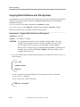
Copying Disk Partitions and File Systems
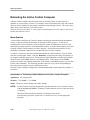
Performing a Warm Reboot on the Active Control Computer
Performing a Cold Reboot on the Active Control Computer
Rebooting the Standby Control Computer
Restoring the Standby Switch
Formatting a Disk or Tape
Replacing a Synchronization Unit (SU) on the STR4 Clock
Replacing a Reference Input Board (RIB) on the STR4
Putting the STR4 into Free-Running Mode
3-5
3-6
3-6
3-7
3-11
3-11
3-14
3-15
3-18
3-20
3-20
3-21
3-22
3-25
3-27
3-29
3-30
3-31
3-32
3-34
3-38
3-39
3-41
3-42
3-45
3-45
3-45
4-1.
4-2.
4-3.
4-4.
4-5.
4-6.
Identifying the Node and Its Administrative Interfaces
Administering Passwords for Console Security
Changing or Deleting a Password
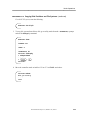
Adding Remote Administrative Interfaces
Administering Node Connections to StarKeeper II NMS
Enabling Directory Assistance and Governing Its Use
4-15
4-18
4-19
4-19
4-21
4-22
BNS-2000 Node Reference, Release 5.0, Issue 1
2-94
2-95
2-98
2-101
2-101
2-105
2-105
xiii
________________
4-7.
4-8.
4-9.
4-10.
4-11.
Handling Directory Entries for Two-way PCs
Enabling the Billing Feature
Establishing a Predefined Destination (PDD)
Changing a Database Entry: Typical Steps
Accessing the Utility Shell
4-24
4-24
4-33
4-37
4-45
5-1.
5-2.
5-3.
5-4.
Replacing or Cleaning Air Filters in Series M2 Shelves
Cleaning the Tape Drive Head in a CCM System
Cleaning the Tape Drive in an ECPU System
Checking a Wrist Strap for Continuity
5-8
5-9
5-9
5-12
6-1.
6-2.
6-3.
6-4.
6-5.
6-6.
6-7.
6-8.
6-9.
6-10.
6-11.
6-12.
6-13.
6-14.
6-15.
6-16.
6-17.
6-18.
6-19.
6-20.
6-21.
6-22.
6-23.
6-24.
6-25.
6-26.
6-27.
6-28.
6-29.
6-30.
6-31.
Diagnostics for a Faulty Module in a BNS-2000 Node
Running Monitor Mode Diagnostics
Recovering From Monitor Mode Diagnostic Failure
Running Loader Mode Diagnostics From Disk or Tape
Recovering From Loader Mode Diagnostic Failure
Running SSM4 Diagnostics
Running STR4 Diagnostics
Running MRCIO Diagnostics
Running MRCM Diagnostics
Collecting Data Transport Data
Collecting Redundancy Data
Collecting Trunking Data
Collecting Operations, Administration, and Maintenance Data
Collecting Rebooting Data
Collecting Diagnostics Data
Collecting Call Processing Data
Testing the Power in a Base Power Unit
Performing Voltage Checks for BNS-2000 Series M2 Shelves
Performing Voltage Checks for Series M1 Shelves
Replacing the Fan Tray in a Series M2 Shelf
Replacing the Fan Tray in a Series M1 Shelf
Checking and Changing Series M2 Shelf Fuses
Checking and Changing BNS-2000 Series M1 Shelf Fuses
Handling System Lockup
Handling Control Computer Booting Problems
Handling Module Recognition and Restoration
Checking a Disk File System
Solving Disk and Tape Drive Access Problems
Obtaining Standby Control Computer Status
Solving Standby Control Computer Problems
Replacing the CTS1 I/O Board
6-19
6-21
6-21
6-22
6-26
6-27
6-28
6-29
6-33
6-36
6-37
6-37
6-38
6-38
6-38
6-39
6-45
6-45
6-46
6-49
6-49
6-50
6-51
6-55
6-56
6-56
6-58
6-59
6-64
6-64
6-66
xiv
BNS-2000 Node Reference, Release 5.0, Issue 1
________________
6-32. Recovering from Multiple Active Control Computers for a CCM
System
6-33. Recovering from Multiple Active Control Computers for an ECPU
System
6-34. Using Bypass with an MRCIO
6-35. Solving MRC Access Problems
6-36. Responding to MRC Alarms
6-37. Correcting MRC Diagnostic Failure
6-38. Correcting MRC Looping or Expected Download
6-39. Solving Console Problems
6-40. Handling CIM and CTRM Failure
6-41. Testing a Series M2 Extension Shelf
6-42. Handling GAR Failure
6-43. Solving End User Inability to Connect
6-44. Resolving End User Problems After Connecting
6-45. Solving End User Modem Pool Problems
7-1.
7-2.
7-3.
7-4.
7-5.
7-6.
7-7.
7-8.
7-9.
7-10.
7-11.
7-12.
7-13.
7-14.
7-15.
7-16.
7-17.
7-18.
7-19.
7-20.
7-21.
Obtaining the Software Registration Key
Disabling Automatic Recovery and Autobackup
Checking the MRC–Console Connection
Preserving the Database
Upgrading a BNS-2000 Software Build or a Compatible Release
Upgrading a Datakit II VCS Software Build
Backing Out of a Software Build Upgrade on an Operational Node
Obtaining the Software Registration Key
Disabling Automatic Recovery and Autobackup
Checking the MRC–Console Connection
Disabling Automatic Recovery and Backup
Preparing for a Redundant Eswitch Module
Preserving the Database
General Procedure for Upgrading BNS-2000 Control Computer and
Disk Hardware
BNS-2000 ECPU System to Release 5.0 CCM System
BNS-2000 ECPU System to Release 5.0 ECPU System
Verifying the Control Computer and Disk Hardware Installation
General Procedure for Upgrading BNS-2000 Switch Complex
Hardware
Upgrading a BNS-2000 Standard Switch Complex to an Extended
Switch Complex System
General Procedure for Upgrading Datakit II VCS Hardware
Modular Cabinet Hardware: CPU System to Datakit II VCS Release
6.0 CCM System
BNS-2000 Node Reference, Release 5.0, Issue 1
6-68
6-69
6-70
6-71
6-73
6-75
6-75
6-76
6-80
6-81
6-82
6-84
6-85
6-86
7-9
7-9
7-10
7-11
7-12
7-17
7-21
7-26
7-27
7-27
7-28
7-29
7-30
7-34
7-35
7-42
7-46
7-47
7-48
7-58
7-59
xv
________________
7-22. Modular Cabinet Hardware: CPU System to Datakit II VCS Release
6.0 ECPU System
7-23. Model 2000 Hardware: CPU System to Datakit II VCS Release 6.0
ECPU System
7-24. Modular Cabinet Hardware: ECPU System to Datakit II VCS Release
6.0 CCM System
7-25. Modular Cabinet Hardware: ECPU System to Datakit II VCS Release
6.0 ECPU System
7-26. Model 2000 Hardware: ECPU System to Datakit II VCS Release 6.0
ECPU System
7-27. Verifying the Datakit II VCS Hardware Installation
7-28. Upgrading a BNS-2000 Software Release: Single Control Computer
7-29. Upgrading a BNS-2000 Software Release: Dual Control Computers
7-30. Upgrading a Datakit II VCS Software Release: Single Control
Computer
7-31. Upgrading a Datakit II VCS Software Release: Dual Control
Computers
7-32. Generating a Node Configuration Database Report
7-33. Obtaining the Software Registration Key
7-34. Disabling Automatic Recovery and Autobackup
7-35. Checking the MRC–Console Connection
7-36. Preserving the Database
7-37. Preparing the System Configuration for Upgrade
7-38. Replacing Disk Hardware on Control Computer 1
7-39. Installing New Software on Control Computer 1
7-40. Retrieving and Upgrading the Database
7-41. Rebooting the Node on Control Computer 1
7-42. Replacing Disk Hardware on Control Computer 0: ECPU System
7-43. Installing New Software on Control Computer 0
7-44. Backing Up the Database
7-45. Rebooting the Node on Control Computer 0
xvi
BNS-2000 Node Reference, Release 5.0, Issue 1
7-66
7-71
7-75
7-80
7-82
7-84
7-85
7-92
7-99
7-105
7-111
7-116
7-116
7-117
7-118
7-119
7-121
7-123
7-124
7-126
7-128
7-130
7-130
7-131
________________
Preface
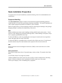
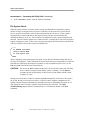
The Node Reference is a compilation of material for node administrators, system installers, and
other network personnel. This document includes the essential information on BNS-2000 and
BNS-2000 VCS node configurations, installation, administration, and database creation, plus
routine operations, maintenance, troubleshooting, and upgrades.
The Data Networking Products Planning Guide, this document, and individual reference
documents for each module are designed to help node and network personnel obtain specific
information as needed, with minimal overlap from document to document.
Complete descriptions of all commands are in the Data Networking Products Commands
Reference.
Important Notice
As of January 1997, Lucent Technologies is merging Datakit II VCS and MPC15 into one BNS2000 hardware platform. The new name for Datakit II VCS is BNS-2000 VCS; the new name for
the MPC15 is BNS-2000 MPC. Ordering will be simplified through the use of one (1) "J"
drawing for initial orders. There will be different software for the BNS-2000 and BNS-2000
VCS but one (1) BNS-2000 documentation set that will include the necessary information for the
BNS-2000, BNS-2000 VCS, and BNS-2000 MPC. Existing Datakit II VCS and BNS-2000
customers will receive the new documentation set when they purchase upgrades.
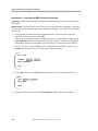
The BNS-2000 hardware platform will consist of the following options:
BNS-2000 — is the BNS-2000 M1/M2 cabinet configuration supporting both low-speed
(M1) and high-speed (M2) modules. This configuration will require BNS-2000 software.
BNS-2000 VCS — is the BNS-2000 VCS M1-only cabinet configuration supporting lowspeed (M1) modules. The M1 cabinet will contain clock/repeater modules as opposed to
CIM/CTRM modules contained in BNS-2000 M1 cabinets. M2 cabinets are not required.
This configuration requires BNS-2000 VCS/Datakit II VCS R6.0 software.
BNS-2000 MPC — is the BNS-2000 MPC M1 Multipurpose Concentrator cabinet
configuration.
BNS-2000 Release 4.0 documentation will be updated to include information on the BNS-2000,
BNS-2000 VCS, and BNS-2000 MPC.
All BNS-2000 offerings described above are managed by StarKeeper II Network Management
System (NMS). (When configuring BNS-2000 VCS, customers select "Datakit II VCS" as the
node option.)
BNS-2000 training courses will be updated to include information on the BNS-2000 VCS and
BNS-2000 MPC offerings.
BNS-2000 Node Reference, Release 5.0, Issue 1
xvii
________________
Preface
Year 2000 Compliance
BNS-2000 Release 4.0, Build 57, and StarKeeper II NMS Release 9.0 provide Year 2000
Compliance through the support of four-digit years in most date fields; two digit years are also
supported in an unambiguous way.
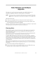
Document Organization
The Node Reference describes the node and its components, and gives procedures for working
with the hardware and software.
Included in this document are
instructions for setting up and installing the hardware and software for specific configurations
of the node
guidance on starting up the system, including testing basic node operations; creating and
maintaining a database; managing and monitoring the system; and performing diagnostics and
basic maintenance
checklists of tasks and procedures for installation, for the initial database configuration, for
troubleshooting, and for upgrading hardware and software to the new release
In brief, the Node Reference contents are as follows:
Node Overview
Node Installation
xviii
This chapter describes the hardware and software components of
the node, including placement of cabinets/shelves, administrative
interfaces, cabling, and software media. The chapter also briefly
lists the main features, as well as the operational and security
features,
of the node.
This chapter provides an overview of the tasks and procedures
involved in installing the node hardware. It includes specific
procedures for assembling the node cabinetry and for the
required power connections for nodes in central office (CO) and
other environments. Also included are instructions for installing
modules in the front of the node; installing and cabling the
appropriate input/output (I/O) distribution boards at the back of
node; installing an internal or external tape drive; and cabling
administrative interfaces, such as the system console and printer.
BNS-2000 Node Reference, Release 5.0, Issue 1
________________
Preface
Node Operations
This chapter describes start-up and routine operating procedures,
including switching to backup components. Included are
instructions for installing the system software, setting the system
time, backing up the database, checking the disk and tape,
configuring the system for recovery, and rebooting.
Node
Administration
This chapter gives a logical order for the steps a node
administrator must take at system start-up to ensure that the node
and administrative interfaces are installed correctly, to minimize
interruptions once the system is booted, and to enable the orderly
addition of information to the configuration database. The
chapter also outlines the commands used to create a database,
and gives instructions for entering information into the database
to configure services and features.
Node Maintenance
This chapter covers the routine tasks associated with care and
handling of the node equipment, and periodic preventive
maintenance for fans, disk drives, tape drives, and battery backup
components.
Node
Troubleshooting
This chapter describes an overall approach to troubleshooting
and then focuses on resolving problems associated with the node
components. It covers node monitoring tasks, such as
responding to system alarm messages, checking light-emitting
diodes (LEDs), and running on-line diagnostic tests, and gives
hardware and software troubleshooting procedures.
Node Hardware and
Software Upgrades
This chapter gives a checklist of the basic steps involved in
upgrading a Control Computer to the latest release, with specific
instructions for upgrading node hardware and software, from one
release to another release, or to a new build or compatible release
of software. Also included are instructions for preserving and
upgrading the database, rebooting the node to complete the
upgrade, and backing out of a database upgrade when necessary.
Appendix.
Node Database
Entry Forms
This appendix includes forms for the node administrator to
photocopy, fill in, and use when entering information into the
configuration database; the forms are also useful for system
record keeping.
Index
Entries cover subject matter in each chapter.
BNS-2000 Node Reference, Release 5.0, Issue 1
xix
________________
Preface
Document Conventions
This document describes two product nodes, the BNS-2000 node and the BNS-2000 VCS node.
It describes two main Control Computer configurations: a new Control Computer Module
(CCM) configuration and an ECPU configuration: the document uses CCM system and ECPU
system to distinguish between the two configurations.
All descriptions, instructions, and procedures apply to both configurations, unless the CCM or
ECPU are specifically cited in the text.
The MRC> system prompt used in the text refers to the maintenance and redundancy control
functions of both the CCM configuration and the ECPU configuration (on an actual ECPU
system, the prompt is seen as MRCM> ).
It also describes two types of switch complexes:
The standard switch complex, which consists of the CMA1/CNA1/CMC3 circuit board
complex, can be used in a BNS-2000 CCM or ECPU system. This switch system is referred
to as standard in the document.
The extended switch complex, which consists of the CTG13/CNA7/CUW1 circuit board
complex, can also be used in a BNS-2000 CCM or ECPU system. This switch system is
referred to as extended in the document.
Special typefaces are used to distinguish the information listed in the following table.
_______________________________________________________________
_______________________________________________________________
Special Typefaces
Commands in the text are shown in bold type
enter or remove ty
_______________________________________________________________
help enter <object>
Optional or variable command parameters in the text are
shown in italic type, enclosed in angle brackets
_______________________________________________________________
Prompts and messages referred to in the text are shown in UTILITY>
type similar to that seen on a screen
_______________________________________________________________
_______________________________________________________________
Function or other keys such as Control are shown as
Control or Escape
The function key that you press to enter commands may be Return
labeled
or Enter or Ret , but is shown as
_______________________________________________________________
_______________________________________________________________
Directory and file names are shown in italic type
/bin/mini-sh
General information that appears in screen output—such as <month, day, year>
the product name, the date and the time, or the release
revision level—is shown in italic type.
_______________________________________________________________
Each term, module, or component name is spelled out with its acronym or abbreviation given in
parentheses at the first use in the text. Thereafter, only the acronym or abbreviation is used.
xx
BNS-2000 Node Reference, Release 5.0, Issue 1
________________
Preface
Related Documentation
Data Networking Products Publications describes the complete set of documentation available
for the product line; see the inside front cover of this volume for ordering information.
Documents you will need to use with this reference include:
Data Networking Products Commands Reference—a complete reference document, with
sample screen output, for the administration commands used with the system.
Data Networking Products Planning Guide—information required to plan and configure a
network of node switches
Data Networking Products Messages Reference—detailed descriptions of system messages
with suggestions for the appropriate response or troubleshooting, for all node and network
personnel
BNS-2000 SMDS Guide—for systems using switched multimegabit data service (SMDS)
Data Networking Products Session Maintenance Guide—for systems using automatic
alternate routing
In addition, reference guides for interface and trunk modules and for concentrators supported by
the system are available; certain documents from other vendors may also be necessary for end
devices connected to the modules.
The BNS-2000 System Description gives an overview of specific BNS-2000 and BNS-2000 VCS
features as well as hardware and software components—from the perspective of the release’s data
services and related capabilities.
The Data Networking Products Terminology publication lists the acronyms and abbreviations
used in the customer document library and briefly defines many technical terms.
BNS-2000 Node Reference, Release 5.0, Issue 1
xxi
________________
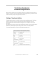
Technical Assistance
and Node Registration
Before working with the node, become familiar with how to get technical assistance when it is
required. You can also save time by obtaining the software registration key to make the release
software and feature packages fully operational, in advance.
Calling a Telephone Hotline
Telephone hotline assistance is available for node operations and administration. If problems
cannot be resolved by local action, technical personnel may be dispatched to your site.
For information on the technical assistance and support services available, see the System
Description.
The information given below describes the available hotline numbers, the account and technical
information you should gather before calling a hotline, and how to escalate problems.
Your account representative will advise which telephone number to call.
__________________________________________
__________________________________________
Telephone Hotline and Node Registration Numbers
Canada
1-800-343-1958
__________________________________________
Germany
0130810992
__________________________________________
Italy
167870510
__________________________________________
0031111399
Japan
__________________________________________
95 800 010-0072
Mexico
__________________________________________
The Netherlands 060224285
__________________________________________
008 1 800 921-8260
South Korea
__________________________________________
United Kingdom 0 800 891760
__________________________________________
1-800-WE-2-CARE (1-800-932-2273)
USA
__________________________________________
BNS-2000 Node Reference, Release 5.0, Issue 1
xxiii
________________
Technical Assistance and Node Registration
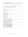
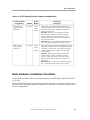
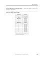
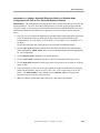
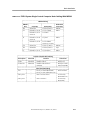
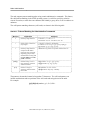
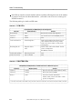
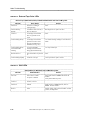
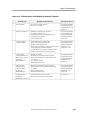
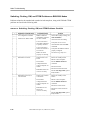
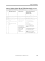
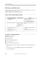
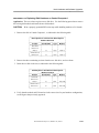
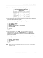
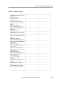
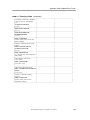
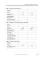
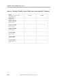
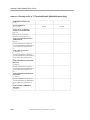
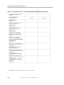
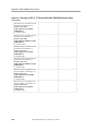
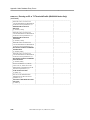
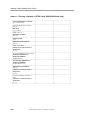
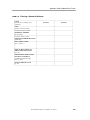
Before calling for assistance from a hotline, collect the information in the following table.
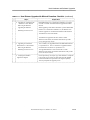
TABLE 1. Information Needed for the Hotline Operator
_____________________________________________________________________________
Name
_____________________________________________________________________________
Telephone and FAX numbers
_____________________________________________________________________________
Company name
_____________________________________________________________________________
System or product name
_____________________________________________________________________________
Software release number
(For all nodes involved in the configuration)
_____________________________________________________________________________
Type of node system
(CCM or ECPU)
_____________________________________________________________________________
Type of switch complex
(standard or extended)
_____________________________________________________________________________
Service Contract or Purchase Order number
_____________________________________________________________________________
Network, node, and/or application configurations
(For information, at the CC0> or CC1> prompt,
type verify <node, shelf, module, group, address> for
BNS-2000 nodes or verify <node, module, group,
_____________________________________________________________________________
address> for BNS-2000 VCS nodes.)
Status reports for virtual circuits involved
(Type display <connections, circuits, eia>, dmeas,
and dstat at the CC0> or CC1> prompts.)
_____________________________________________________________________________
Messages received when performing diagnostics
(For exact text of messages, type diagnose commands
at the CC0>, CC1>, MRC>, or MRCM>
prompts; by typing di at the MONITOR>
prompt; and by typing run diag at the LOADER>
_____________________________________________________________________________
prompt. Print and attach the messages to this form.)
xxiv
BNS-2000 Node Reference, Release 5.0, Issue 1
________________
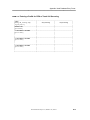
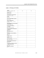
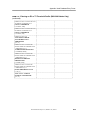
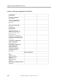
Technical Assistance and Node Registration
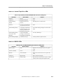
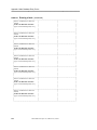
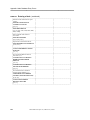
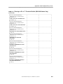
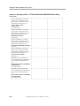
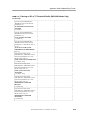
Information Needed for the Hotline Operator (continued)
_____________________________________________________________________________
Name
_____________________________________________________________________________
Other console messages or alarms
(Print and attach to this form the exact text of
messages or alarms related to problem.)
_____________________________________________________________________________
Recent configuration changes, relevant problems,
and machine usage data (Attach records to this
_____________________________________________________________________________
form.)
Problem or question
(Include impact on users at the site.)
_____________________________________________________________________________
Severity of call
(Obtain code number from the following table.)
_____________________________________________________________________________
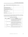
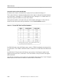
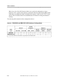
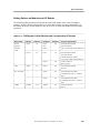
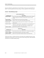
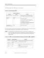
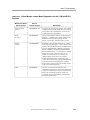
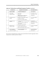
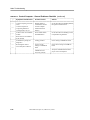
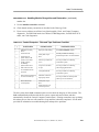
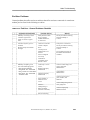
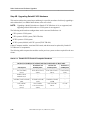
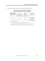
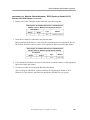
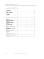
TABLE 1.
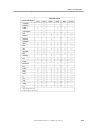
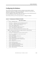
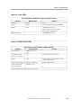
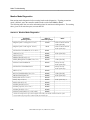
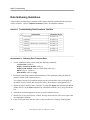
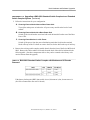
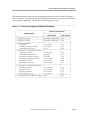
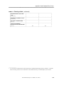
To assess the severity of a node or system problem before calling the hotline, use the following
table. Problem descriptions are coded from 1 (the most severe) to 4; these codes help the hotline
consultant deal with the nature and urgency of system problems.
______________________________________________________________________
______________________________________________________________________
Severity Codes for System Problems
Code
Problem
Description
______________________________________________________________________
Major system failure
The node, network, or critical application is inoperative. The
1
user environment is currently adversely affected, or will be
adversely affected within 24 hours. The appropriate customer
resources will be made available to the hotline support staff
while the problem or request is being worked.
______________________________________________________________________
2
Partial system failure A critical service-affecting feature of the node, network, or
application
is
inoperative,
or
the
customer
cannot
commit
the
appropriate resources to resolve the problem or request. The
user environment is not currently adversely affected, but may be
adversely affected within 5 business days.
______________________________________________________________________
Inoperative or missing Of the system, network, or application. The effect is not
3
feature
critical; users will not be adversely affected, but a solution is
required.
______________________________________________________________________
4
These may involve system enhancements, comments or requests
All other problems
on the user documentation, and other service requests.
______________________________________________________________________
BNS-2000 Node Reference, Release 5.0, Issue 1
xxv
________________
Technical Assistance and Node Registration
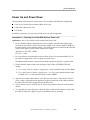
Escalation Procedure
If you are concerned about the rate of progress in resolving a problem, escalate the problem to the
hotline management simply by calling the hotline and requesting escalation. Have the associated
trouble report (TR) or trouble ticket number, previously given to you by the hotline, available.
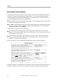
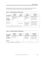
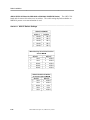
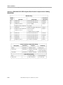
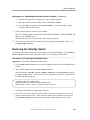
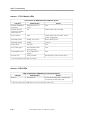
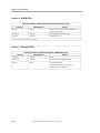
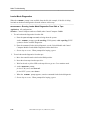
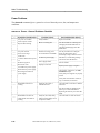
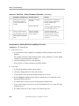
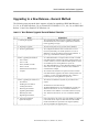
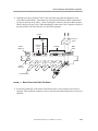
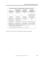
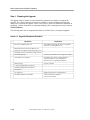
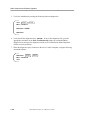
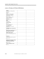
Registering the Node
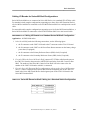
To make the release software fully functional on the node, you must enter a software registration
key using the install registration command. This key is obtained from the Customer Assistance
Center (CAC) at: 1-800-WE-2-CARE. (Customers outside the USA should call their supplier or
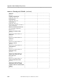
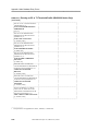
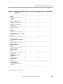
regional support organization.) Before calling 1-800-WE-2-CARE, you will need the information
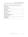
listed in the following form.
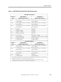
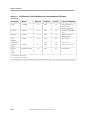
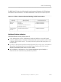
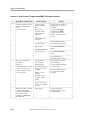
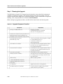
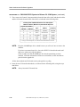
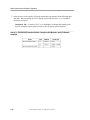
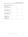
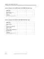
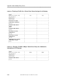
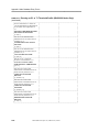
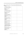
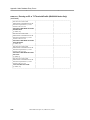
TABLE 2. Information Needed When Calling for Software Registration Key
_____________________________________________________________________________
Company name
(Owner of hardware and software.)
_____________________________________________________________________________
Node administrator’s name
_____________________________________________________________________________
Node administrator’s telephone
and FAX numbers
(Include area code.)
_____________________________________________________________________________
Node administrator’s address
(Include zip code.)
_____________________________________________________________________________
Location of hardware
(Address and zip code.)
_____________________________________________________________________________
Serial number of Control Shelf
(Obtain from barcode on back of shelf.)
_____________________________________________________________________________
Number of Series M2 Extension Shelves
_____________________________________________________________________________
Number of Series M1 Control Shelves
_____________________________________________________________________________
Number of Series M2 Port Shelves
_____________________________________________________________________________
xxvi
BNS-2000 Node Reference, Release 5.0, Issue 1
________________
Technical Assistance and Node Registration
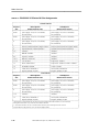
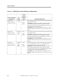
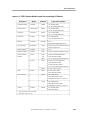
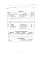
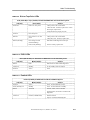
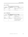
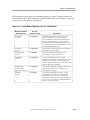
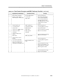
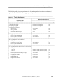
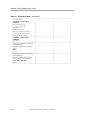
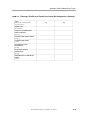
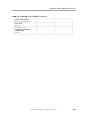
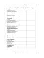
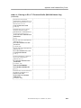
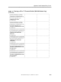
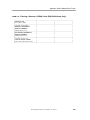
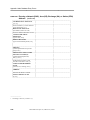
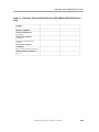
Information Needed When Calling for Software Registration Key
(continued)
_____________________________________________________________________________
Software release number
(Obtain from tape label.)
Example: 2BN4.0 for BNS-2000 VCS.
_____________________________________________________________________________
Example: 3VS6.0 for BNS-2000 VCS nodes.
Software build number
(Obtain from tape label.)
_____________________________________________________________________________
Node identifier
(The serial number of the SCSI/DKI module or
CCM in Control Computer 0.
Obtain the number using dstat <mod>.
_____________________________________________________________________________
(Example: 12345)
Software serial number
(Obtain from barcode label on tape.)
_____________________________________________________________________________
Software Feature Package Activation Identifier(s)
(Obtain from the red feature card(s) for
each software feature package ordered.)
Example: a6be-76yiX
_____________________________________________________________________________
Software registration key
(The CAC will supply:
1-800-WE-2-CARE in the USA.)
_____________________________________________________________________________
TABLE 2.
BNS-2000 Node Reference, Release 5.0, Issue 1
xxvii
________________
Technical Assistance and Node Registration
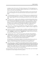
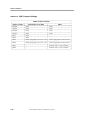
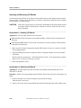
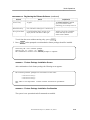
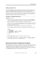
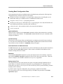
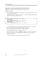
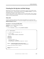
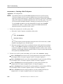
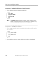
After receiving the information in the form, the CAC specialist will give you a software
registration key. Record this key for later use with the install registration command. The
procedure for using the install registration command to enter the software key and install feature
packages is given in the Node Operations chapter. Once the software registration key is entered
in the database, it is not needed again during normal node operations.
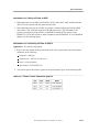
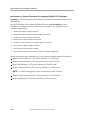
Re-entering the key is required when
the disk drive is replaced
the disk is reformatted
the data saved prior to registering the node is retrieved
A new key is required when
a new software release is installed
a new software build is installed
a new feature package is installed
a Control Computer Module (CCM) or SCSI/DKI module is replaced
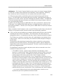
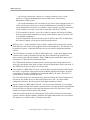
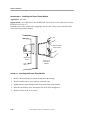
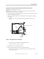
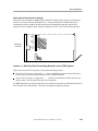
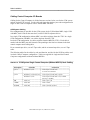
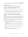
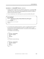
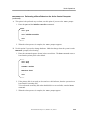
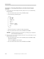
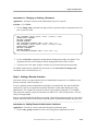
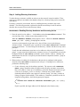
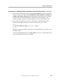
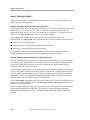
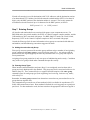
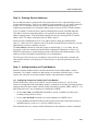
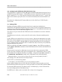
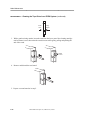
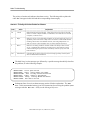
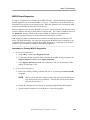
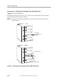
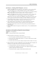
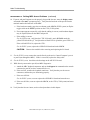
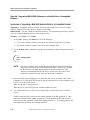
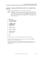
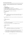
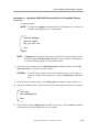
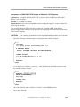
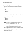
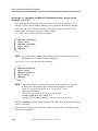
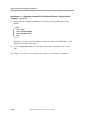
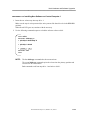
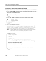
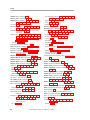
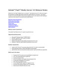
The following figures show the location of the serial number on the CCM, or SCSI/DKI module
(ECPU system). The serial number can also be obtained from the dstat <mod>
report for the CCM or SCSI/DKI module.
Board Number 20875
(Serial Number)
This is the Node ID
FIGURE 1.
xxviii
Node ID Number on Control Computer Module (CCM)
BNS-2000 Node Reference, Release 5.0, Issue 1
________________
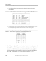
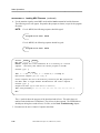
Technical Assistance and Node Registration
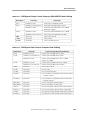
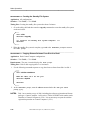
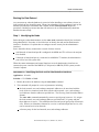
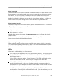
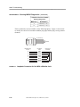
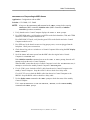
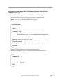
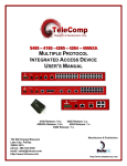
# 20875
(Serial Number)
This is the Node ID
FIGURE 2.
Node ID Number on SCSI/DKI Module in an ECPU System
BNS-2000 Node Reference, Release 5.0, Issue 1
xxix
________________
Technical Assistance and Node Registration
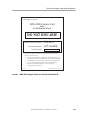
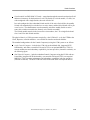
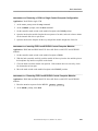
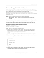
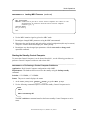
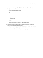
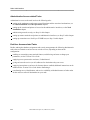
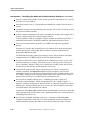
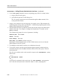
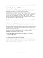
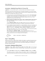
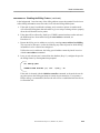
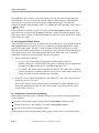
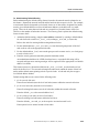
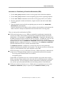
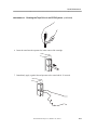
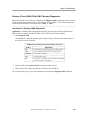
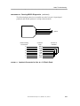
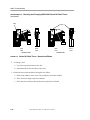
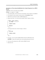
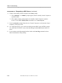
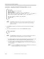
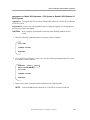
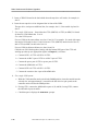
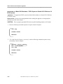
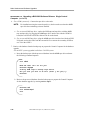
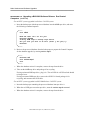
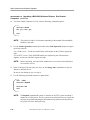
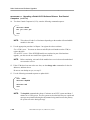
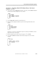
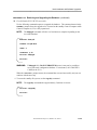
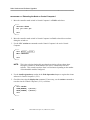
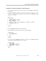
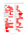
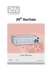
With each Software Feature Package, you will receive a Red Feature Card that shows the
software Activation Identifier code. Accompanying the card is a notice titled "READ ME
FIRST!!" that gives instructions for registering software. Save the notice and the Red Feature
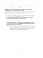
Card for future use. The following figures show these sample feature cards.
Comcode 107219784
READ ME FIRST!!
BNS-2000 Software Registration Notice
When installing a BNS-2000 node for the first time, you must register the software
prior to having it become fully functional. If instead, you have recently purchased a software
feature package to add to your node, you need to re-register your node software, making the new
feature package functional.
In order to register software on a BNS-2000 node, you must execute the install registration
command. Successful execution of this command requires a Software Registration Key from the
Customer Assistance Center (CAC) at 1-800-WE2-CARE. Node functionality will
be blocked until the registration procedure is successful.
Each BNS-2000 node has a unique Software Registration Key which is a function of the Node
Identifier, Software Release Number, Software Build Number, and Activation Identifier(s). Prior
to calling the CAC, execute the install registration command on your node and take note of the
following values:
• Node Identifier
• Software Release Number
• Software Build Number
Activation Identifier(s) are obtained from the RED Feature Card(s) which accompany this notice.
The number of feature cards you receive for each node depends on the number of feature packages
ordered. (Note that the Full Feature Package consists of a single feature card.) When you call the
CAC to obtain a software key, make sure you have all feature cards for a particular system.
Once you receive the Software Registration Key from the CAC, execute the install registration
command and enter the key. The key will be stored in the node software and the node will become
fully operational. The key is not needed again during normal operations;
however, it is good practice to save it. You would need to re-enter the key if the disk was replaced
or reformatted.
When a new software release is installed on a node, a new key will be required. Replacing the
CCM board would also require a new software key.
When calling the CAC to obtain your Software Registration Key, you will be asked for some
additional information which will enable us to serve you better in the future. Please take some
time to fill out the back of this form prior to calling the CAC for your registration key.
Please save this notice, along with all RED Feature Cards,
in a safe place for future use.
FIGURE 3.
xxx
BNS-2000 Software Registration Notice Card
BNS-2000 Node Reference, Release 5.0, Issue 1
________________
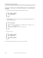
Technical Assistance and Node Registration
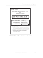
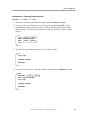
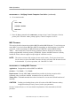
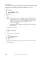
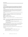
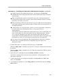
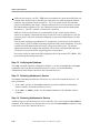
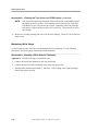
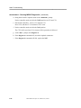
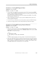
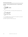
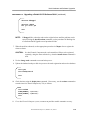
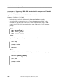
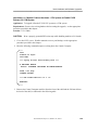
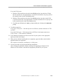
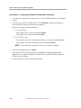
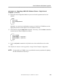
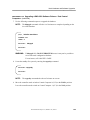
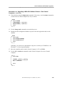
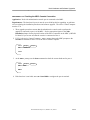
COMCODE: 107761918
BNS-2000 Feature Card
FULL
FEATURE PACKAGE
DO NOT DISCARD!
Software Release Number:
Activation Identifier:
2BN4.0
jrr7-awa6n
Node Identifier:
This Activation Identifier enables you to activate this feature package for
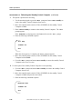
one node. Follow these steps:
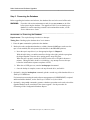
1.) Run the "install registration" command and take note of the following:
Software Release Number, Node Identifier, and Software Build Number.
2.) Call the AT&T Customer Assistance Center with this information and
receive a Software Registration Key. Phone 1-800-WE2-CARE.
3.) Enter the Software Registration Key on the node using the
"install registration" command.
01/95-B
FIGURE 4.
SERIAL NUMBER: BNS-2000/4.0/15/0412
BNS-2000 Sample Feature Card with Activation ID
BNS-2000 Node Reference, Release 5.0, Issue 1
xxxi
________________
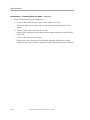
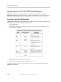
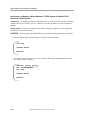
Technical Assistance and Node Registration
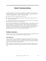
Comcode 106972698
READ ME FIRST!!
Datakit® II VCS Software Registration Notice
When installing a Datakit® II VCS node for the first time or upgrading to a new software release,
you must register the software prior to having it become fully functional. If instead, you have
recently purchased a software feature package to add to your node, you need to re-register your
node software, making the new feature package functional.
In order to register software on a Datakit II VCS node, you must execute the install registration
command. Successful execution of this command requires a Software Registration Key from the
Customer Assistance Center (CAC) at 1-800-WE2-CARE. Node functionality will be blocked
until the registration procedure is successful.
Each Datakit II VCS node has a unique Software Registration Key which is a function of the
Node Identifier, Software Release Number, Software Build Number, and Activation Identifier(s).
Prior to calling the CAC, execute the install registration command on your node and take note
of the following values:
• Node Identifier
• Software Release Number
• Software Build Number
Activation Identifier(s) are obtained from the RED Feature Card(s) which accompany this notice.
The number of feature cards you receive for each node depends on the number of feature packages
ordered. (Note that the Full Feature Package consists of a single feature card.) When you call the
CAC to obtain a software key, make sure you have all feature cards for a particular system.
Once you receive the Software Registration Key from the CAC, execute the install registration
command and enter the key. The key will be stored in the node software and the node will become
fully operational. The key is not needed again during normal operations; however, it is good
practice to save it. You would need to re-enter the key if the disk was replaced or reformatted.
When a new software release is installed on a node, a new key will be required. Replacing the
CCM board would also require a new software key.
When calling the CAC to obtain your Software Registration Key, you will be asked for some
additional information which will enable us to serve you better in the future. Please take some
time to fill out the back of this form prior to calling the CAC for your registration key.
Please save this notice, along with all RED Feature Cards,
in a safe place for future use.
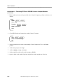
FIGURE 5.
xxxii
BNS-2000 VCS Software Registration Notice Card
BNS-2000 Node Reference, Release 5.0, Issue 1
________________
Technical Assistance and Node Registration
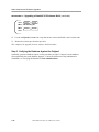
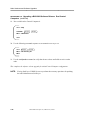
COMCODE: 107416133
DATAKIT® II VCS Feature Card
FULL
FEATURE PACKAGE
DO NOT DISCARD!
Software Release Number:
Activation Identifier:
3VS6.0
b4t8-ja3kh
Node Identifier:
This Activation Identifier enables you to activate this feature package for
one node. Follow these steps:
1.) Run the "install registration" command and take note of the following:
Software Release Number, Node Identifier, and Software Build Number.
2.) Call the AT&T Customer Assistance Center with this information and
receive a Software Registration Key. Phone 1-800-WE2-CARE.
3.) Enter the Software Registration Key on the node using the
"install registration" command.
03/09-C
FIGURE 6.
SERIAL NUMBER: dkii/6.0/15/0808
BNS-2000 VCS Sample Feature Card with Activation Identifier
BNS-2000 Node Reference, Release 5.0, Issue 1
xxxiii
________________
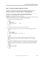
Node Overview
Physical Description
Architecture
Node Cabinetry
Power Distribution
Power Components
Interface Modules
Administrative Interfaces
Shelf Identification
Cables and Cabling Equipment
Software Media
Disk Resources and Node Configuration
Node Features
1-4
1-4
1-7
1-20
1-20
1-21
1-21
1-23
1-29
1-29
1-30
1-35
1-36
1-37
1-38
Main Features
Operational Features
Security Features
BNS-2000 Node Reference, Release 5.0, Issue 1
________________
Node Overview
The node provides the services required for asynchronous and synchronous data transfers needed
for local area networks (LANs), as well as domestic and international private and public wide
area networks (WANs). A node can be configured with two types of shelf combinations:
A BNS-2000 node is configured with a combination of Series M2 Shelves and Series M1
Shelves; it has a 200 Mb backplane. The switching function is located in a separate Series M2
Shelf. It generates and repeats timing signals through one board, which is located in a Series
M1 Shelf.
A BNS-2000 node is a fast-packet switching product that provides the high-speed services
required for local area network (LAN) interconnect via Frame Relay, and for interworking
with devices that comply with the Switched Multimegabit Data Service (SMDS) definition
and the Institute for Electrical and Electronics Engineers (IEEE) 802.6 standard for
metropolitan area networks (MANs). The node can serve as a platform to support a BNS-2000
SMDS network.
An implementation of Asynchronous Transfer Mode (ATM) technology, the node switches
data in the cell format used in IEEE 802.6 and SMDS. This technology supports dedicated
high-bandwidth, high-capacity data switching.
A BNS-2000 VCS node is configured with a combination of one or more Series M1 Shelves; it
has an 8 Mb backplane. The switching function is located on a board that resides in the Series
M1 Shelf. It generates and repeats timing signals through two separate boards, which are
located in a Series M1 Shelf.
A BNS-2000 VCS node interconnects host computers, terminals, modems, printers, and other
data processing devices for communication over short and long distances. In addition, it
serves as a platform for interworking with other Lucent Technologies nodes and for
internetworking with LAN/WAN segments, including access to packet switched networks
worldwide.
The Series M1 Shelves of both BNS-2000 and BNS-2000 VCS nodes can be configured with two
types of Control Computers in single and redundant schemes:
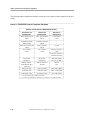
For the BNS-2000 and BNS-2000 VCS nodes, a Control Computer Module (CCM) system
contains the following modules and their associated I/O boards: a Control Computer Module
(CCM) with or without remote maintenance and redundancy control capabilities—which is
provided by a Maintenance and Redundancy Control (MRC) function—a
Clock/Trunk/Repeater Module (CTRM), plus a digital data storage (DDS) tape drive (which
can reside in an internal slot or be external).
BNS-2000 Node Reference, Release 5.0, Issue 1
1-3
________________
Node Overview
For a BNS-2000 node, the ECPU system contains the following modules and their associated
I/O boards: a Control Computer including a CTRM, a Disk/Tape Subsystem, and a
Maintenance and Redundancy Control Module (MRCM) when a redundant Control Computer
is used.
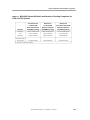
For a BNS-2000 VCS node, the ECPU system contains the following modules and their
associated I/O boards: the Control Computer, including a Switch, a Clock, and a Repeater
module, along with a Disk/Tape Subsystem and a Maintenance and Redundancy Control
Module (MRCM) when a redundant Control Computer is used.
BNS-2000 nodes running CCM or ECPU systems can be configured with two types of switch
complexes: the extended—which includes the STR4 Stratum Clock—or the standard, which
includes the SSM4 Stratum Clock. Either switch complex resides in the Series M2 Switching
Shelf.
Physical Description
The BNS-2000 and BNS-2000 VCS nodes have a modular architecture, which allows for
installation of cabinets at central or separate physical locations. This modular architecture also
allows for cabinet-by-cabinet configuration of node services. A node has control, switch, and
administrative interface functions, and provides interface capabilities for asynchronous,
synchronous, multiplexed host, X.25/X.75, and high-speed frame relay services.
Redundant control and switching capabilities are optional. The sections that follow describe the
node, and its central hardware and software components.
Architecture
The shelves in a BNS-2000 or BNS-2000 VCS node configuration are interconnected to allow the
various interface and trunk modules to transfer information. The interconnection method differs
according to the shelves used in the configuration:
A BNS-2000 node is configured with Series M2 and Series M1 Shelves interconnected via the
Series M2 Switch Shelf as the center of the configuration. This architecture configuration is
known as a star topology. The star topology of a BNS-2000 system has the 200 Mbps cell
relay-based switch complex at the center. This switch complex is connected to a combination
of shelf types designed for high-speed data switching and for centralized node control and
management. Two types of switch complexes can exist in a Series M2 Switch Shelf: the
extended—which includes the STR4 Stratum Clock—or the standard, which includes the
SSM4 Stratum Clock.
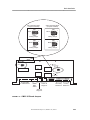
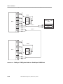
As the following two figures show, the star architecture of BNS-2000 nodes can assume
various combinations of Series M1 and Series M2 Shelves. The minimum configuration
consists of one Series M2 Switch Shelf and one Series M1 Control Shelf.
Refer to sections later in this chapter for more detailed explanations of BNS-2000 shelf
configurations.
1-4
BNS-2000 Node Reference, Release 5.0, Issue 1
________________
Node Overview
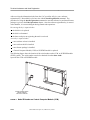
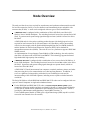
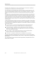
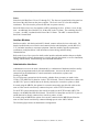
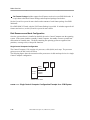
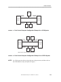
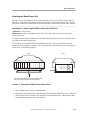
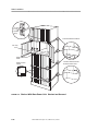
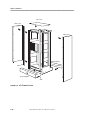
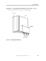
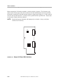
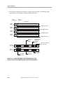
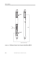
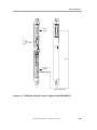
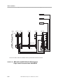
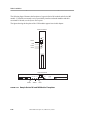
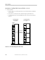
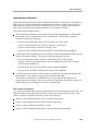
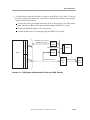
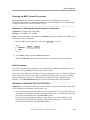
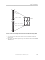
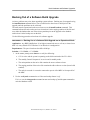
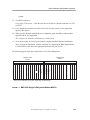
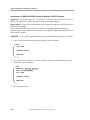
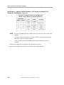
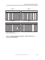
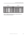
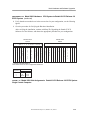
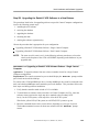
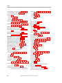
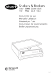
A standard shelf configuration, as shown in the following figure, could consist of the required
Series M2 Switch Shelf and Series M1 Control Shelf, another optional Series M1 Control
Shelf, two optional Series M1 Port Shelves, and three optional Series M2 Extension Shelves.
(The three Series M2 Extension Shelves are the maximum number of extension shelves that
can be added for this type of standard shelf configuration.)
M1
Control Shelf
M2
Extension Shelf
M1
Control Shelf
M2
Switch Shelf
M2
Extension Shelf
M1
Port Shelf
M2
Extension Shelf
M1
Port Shelf
FIGURE 1-1.
BNS-2000 Standard Star Architecture Example
BNS-2000 Node Reference, Release 5.0, Issue 1
1-5
________________
Node Overview
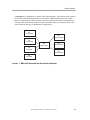
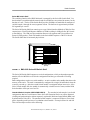
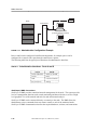
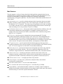
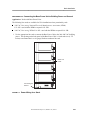
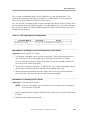
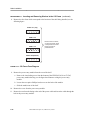
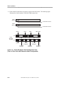
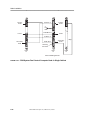
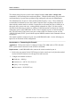
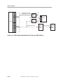
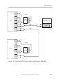
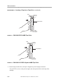
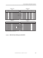
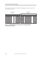
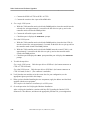
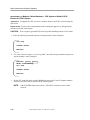
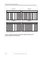
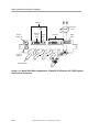
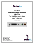
An extended shelf configuration, as shown in the following figure, could consist of the
required Series M2 Switch Shelf and Series M1 Control Shelf, another optional Series M1
Control Shelf, and five optional Series M2 Extension Shelves. (The five Series M2 Extension
Shelves are the maximum number of extension shelves that can be added for this type of
switching module complex, which is referred to as the extended switch complex.)
M2
Extension Shelf
M2
Extension Shelf
M1
Control Shelf
M2
Switch Shelf
M2
Extension Shelf
M1
Control Shelf
M2
Extension Shelf
M2
Extension Shelf
FIGURE 1-2.
1-6
BNS-2000 Extended Star Architecture Example
BNS-2000 Node Reference, Release 5.0, Issue 1
________________
Node Overview
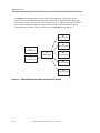
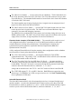
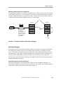
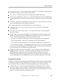
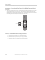
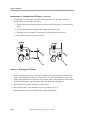
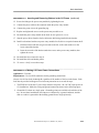
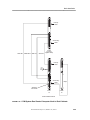
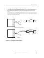
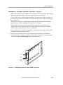
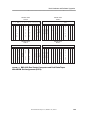
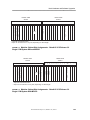
A BNS-2000 VCS node is configured with one or more Series M1 Shelves interconnected via
a common communications bus. This configuration is known as bus architecture.
Series M1
Control Shelf
Series M1
Control Shelf
Series M1
Port Shelf
Series M1
Port Shelf
FIGURE 1-3.
BNS-2000 VCS Bus Architecture
Node Cabinetry
A node can be configured with the following combinations of types of shelves:
A BNS-2000 node must contain one Series M2 Switch Shelf and one Series M1 Control
Shelf. Up to five Series M2 Extension Shelves or up to seven Series M1 Shelves (including
Control Shelves) can be added. However, the total number of shelves in a node is limited to
eight.
BNS-2000 node configurations with up to three Series M2 Extension Shelves use the standard
switch complex along with multi-coax intershelf cabling. When the standard configuration of
three extension shelves is upgraded to the maximum configuration of five Series M2
Extension Shelves, the extended switch complex and high density intershelf cabling are
required.
NOTE:
BNS-2000 node configurations that include the Stratum 4 Clock upgrade also
require the extended switch complex.
A BNS-2000 VCS node must contain one Series M1 Control Shelf. Each node can have a
maximum of eight Series M1 shelves.
BNS-2000 Node Reference, Release 5.0, Issue 1
1-7
________________
Node Overview
Each node can be configured with a variety of modules (plug-in circuit packs), depending on
switching and service requirements; see the Planning Guide.
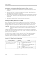
The central office (CO) environment requires that node cabinets be stacked and wired in a CO
frame, and includes additional components, such as the Alarm Relay Unit (ARU). The ARU is
mounted in a special slot at the top of the CO frame and connected to the Series M1 Control
Shelf.
Series M2 shelves are designed for placement of modules in horizontal slots; Series M1 shelves
are designed for placement of modules in vertical slots. Switching, control, interface, or trunk
modules are located in slots in the front of each shelf. Shelf slots are designated by numbers that
identify module addresses in the node database. Within each shelf, the backplane carries data,
timing and contention signals, and power to the input/output (I/O) distribution boards associated
with the modules.
All processing and interface functions in the node are performed by the modules. Most modules
have associated I/O boards that plug into pin fields on the rear of the backplane. The I/O boards
connect the modules to compatible user equipment or to other modules. Modules are available in
the following categories:
Switch Shelf modules—provide clock and switching functions which control the node
backplane signals and data transport for BNS-2000 nodes with 200 Mb backplanes.
Control Shelf modules—include the processor, disk and tape, and remote maintenance
capabilities for all BNS-2000 nodes; and for BNS-2000 VCS nodes, they also include the
Clock, Switch, and Repeater modules.
interface modules—control communication with devices such as terminals and host
computers connected to the local node and the switching network
trunk modules—communicate with other nodes or multiplexers and concentrators.
The figures in this chapter illustrating the shelves show the slots reserved for specific modules;
the unreserved slots can contain additional control, interface, or trunk modules, depending on the
shelf functions.
The overall unloaded weight of a Series M1 shelf is approximately 100 pounds and of a Series
M2 shelf about 175 pounds.
1-8
BNS-2000 Node Reference, Release 5.0, Issue 1
________________
Node Overview
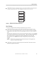
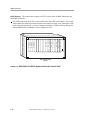
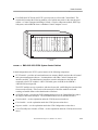
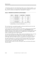
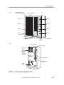
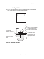
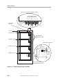
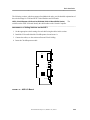
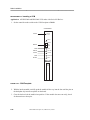
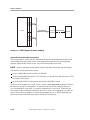
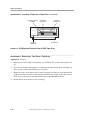
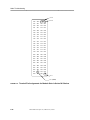
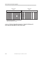
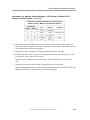
Series M2 Switch Shelf
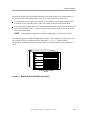
The switching function of the BNS-2000 node is managed by the Series M2 Switch Shelf. It is
here that data is routed through the network and all call addresses are retained in memory for the
duration of a call. The bus in the Switch Shelf provides 200 Mbps of bandwidth for transport of
variable length (1 through 44 octets) segments of data. The data rate is approximately 460,000
full segments per second.
The Series M2 Switch Shelf can contain up to seven Cabinet Interface Modules (CIMs) for fiber
connections to Clock/Trunk/Repeater Modules (CTRMs) residing in 8 Mbps Series M1 Control
or Port Shelves. The CIM provides translation between cell segments and Universal Receiver
Protocol (URP) packets. Each CIM module in the Switch Shelf requires a CMC2 I/O board.
The Switch Shelf has 14 horizontal physical slots.
2
0
0
M
B
P
S
B
a
c
k
p
l
a
n
e
.
.
Power
.
.
.
.
12
.....
......
Power
.....
......
....
Fuses
.....
...... . . . . . . . . . . . . . . .
Power
.....
......
....
Power
.....
..
..
11
10
9
8
7
CIM
6
CIM
5
CIM
4
CIM
..
3
..
0/B
Switch
0/A
Switch
2
1
.
........
..........
..........
..........
..........
..........
..........
..........
..
.............
..........
..........
..........
.......
M2 Switch Shelf
(Front)
FIGURE 1-4.
BNS-2000 Series M2 Switch Shelf
The Series M2 Switch Shelf supports two switch configurations, which are dependent upon the
number of Series M2 Shelves used in the configuration and the type of Stratum 4 Clocking
required.
Both configurations require two switch modules—an active module and a standby that mirrors the
memory of the active. The node is automatically configured for a single Switch module when the
system is powered up. After the second Switch module is configured and put into service, if the
active Switch module fails, the standby is automatically switched to active status, and the failed
Switch module will be put out of service.
Standard Switch Complex (CMA1/CNA1/CMC3).
The standard switch complex is used with
configurations that have a maximum of three Series M2 Extension Shelves or require Stratum 4
clocking and synchronization without separately replaceable Reference Input Boards (RIBs) and
Synchronization Units (SUs). The standard switch complex is composed of three or four circuit
packs, depending on the presence of a redundant switch module. It occupies Slots 0/A and 0/B.
This switch complex consists of the following:
BNS-2000 Node Reference, Release 5.0, Issue 1
1-9
________________
Node Overview
The CMA1 Switch Module — can be used in pairs for redundancy. The Switch module uses
the CNA1 Intershelf Cable/Clock (ICC) I/O board. The CNA1 has connectors for up to three
Series M2 Shelves. The redundant Switch module is located in the slot in front of the Stratum
4 Clock (the CMC3 I/O board).
The Switch modules must be placed in physical slot 1 (logical slot 0/A) and physical slot 2
(logical slot 0/B) in the Series M2 Switch Shelf.
The CMC3 Stratum 4 Clock (SSM4) — uses the CMC3 I/O board located at the rear of the
node in physical slot 2 (logical slot 0/B). The CMC3 has two External Reference Input
connectors, plus status and debugging connectors.
The SSM4 provides synchronization for the primary and secondary timing references on an
SMDS-connected node. The CMC3 also provides status reports for conditions such as power
supply failure, fan failure, or high temperature for the Series M2 Shelves.
The extended switch complex is used
with configurations that have a maximum of five Series M2 Extension Shelves and require
extended Stratum 4 clocking and synchronization. Extended Stratum 4 clocking and
synchronization includes separately replaceable Reference Input Boards (RIBs) and
Synchronization Units (SUs).
Extended Switch Complex (CTG13/CNA7/CUW1).
A fully configured Extended Switch Complex (meaning, those configurations with a redundant
switch) consists of circuit packs that include the following:
The CTG13 Extended Switch Module — has integrated Stratum 4 Clock (STR4)
synchronization units. The primary CTG13 switch module resides in Slot 0/A; the redundant
CTG13 switch module resides in Slot 0/B.
The CNA7 Extended Cable/Clock and RIB Status I/O Board — has status and debug
connectors, along with slots and connectors for two separately replaceable reference input
boards (RIBs). The CNA7 also has five connectors for high density intershelf cables that
connect to Series M2 Extension Shelves, numbered 1, 2, 3, 6, and 7.
Along with its module board—the CTG13—the CNA7 resides in Slots 0/A and Slot 0/B.
The CUW1 RIB supports T1, E1, or 64KCC functions. Both RIBs must support the same
function type. Each RIB has two LEDs, one green and one red. See Node Troubleshooting
for an explanation of LED states.
Series M2 Extension Shelf
The Series M2 Extension Shelf, with 14 horizontal physical slots, is designed for high-speed
interface modules. A node with a Standard Switch Complex can have up to three Series M2
Extension Shelves, which are numbered 1, 2, and 3. A node with an Extended Switch Complex
can have up to five Series M2 Extension Shelves, which are numbered 1, 2, 3, 6, and 7.
1-10
BNS-2000 Node Reference, Release 5.0, Issue 1
________________
Node Overview
Series M2 Switch and Series M2 Extension Shelves are identical; however, Extension Shelves
use an Extension Intershelf Shelf Cable/Clock (ECC) I/O board in place of the CNA1:
For a standard switch complex, the CNA2 ECC I/O board goes in the back of physical slot 1.
It connects to one of the three ports on the CNA1 board in the Series M2 Switch Shelf.
For an extended switch complex, the CNA8 Enhanced Extension Cable/Clock I/O Board goes
in the back of physical slot 1. It connects to one of the five ports on the CNA7 board in the
Series M2 Switch Shelf.
NOTE:
When upgrading nodes to the extended configuration, see the Planning Guide.
All remaining slots are available for high-speed modules. These modules can reside in any slots
not occupied by ECC I/O boards in shelves numbered 1, 2, 3, 6, or 7. With extended
configurations, GAR and all Series M2 trunk modules can only reside in shelves numbered 1, 2,
and 3.
2
0
0
M
B
P
S
B
a
c
k
p
l
a
n
e
.
.
Power
.....
......
Power
........
......
Fuses
......
. ... ... ... ... ...
.....
.
.
.....
......
....
.....
..
..
.
Power
..
Power
..
28
27
.
26
25
24
23
22
21
20
19
18
17
16
.
........
..........
..........
..........
..........
..........
..........
..........
..........
..........
..........
..........
..........
..
Series M2 Extension Shelf
(Front)
FIGURE 1-5.
BNS-2000 Series M2 Extension Shelf
BNS-2000 Node Reference, Release 5.0, Issue 1
1-11
________________
Node Overview
Series M1 Control Shelf
The entire node is controlled by a Control Computer that resides in a Series M1 Control Shelf, or
dual Control Computers (one active, one standby) that reside in one or two Series M1 Control
Shelves. The Series M1 Control Shelf, with an 8 Mbps backplane, has 16 vertical physical slots
for modules. For greater reliability, an optional redundant Control Computer can provide backup
to the first. The redundant Control Shelf must be located in a shelf with a higher number than the
primary Control Shelf.
The Control Computer configurations supported in the Series M1 Control Shelf are the CCM
system and the ECPU system. Each is described in this section.
B
A
C
K
P
L
A
N
E
P
O
W
E
R
P
O
W
E
R
R
E
D
U
N
D
A
N
T
P
O
W
E
R
0
T
A
P
E
*
C
C T
C R
M M
1 2 3 4 5 6 7 8 9 10 11 12 13 14 15
* Tape drive can be external.
FIGURE 1-6.
BNS-2000 Series M1 Control Shelf
B
A
C
K
P
L
A
N
E
P
O
W
E
R
P
O
W
E
R
E
S
W
I
T
C
H
R
E
D P
U O
N W
D E
A R
N
T
(S
H
E
L
F
T
A
P
E
*
C
C
M
0)
0
1 2 3 4 5 6 7 8 9 10 11 12 13 14 15
* Tape drive can be external.
FIGURE 1-7.
1-12
C
L
O
C
K
/
R
E
P
E
A
T
E
R
BNS-2000 VCS Series M1 Control Shelf
BNS-2000 Node Reference, Release 5.0, Issue 1
________________
Node Overview
The Control Computer Module system consists of a Control Computer Module
(CCM) with or without remote maintenance and redundancy control capabilities, a DDS tape
drive (which can reside in an internal slot or be external), and associated I/O boards.
CCM System.
A CCM system must contain a module that generates and repeats timing signals between
shelves. In a BNS-2000 node, the timing and repeater functions, along with status polling, are
combined in one module, which is the Clock/Trunk/Repeater Module (CTRM). In a BNS-2000
VCS node, the timing and repeater functions are performed in two separate modules, which are
the Clock and Repeater modules.
In addition, the switching function in a BNS-2000 VCS node is performed as a function of the
CCM system. (It is unlike the BNS-2000 node whose switching function is performed in the
Series M2 Switch Shelf.) Therefore, the CCM system in a BNS-2000 VCS node must contain a
Switch module.
When a redundant Control Computer is used, a second CCM may be placed in the same physical
cabinet or in any adjacent cabinet, and must include remote maintenance capabilities.
CCM—provides on-board random access memory (RAM), dual SCSI buses, and a hard disk
containing the node software and database. The CCM runs the call control and system
management software. It communicates with other Control Computer and interface modules.
The CCM sets up, responds to, and takes down calls, establishing the route that data from a
sender will take. It also receives the status poll of interface modules and prints warnings of
module failure.
The hard disk on the module board contains all the software required for node operations,
including on-line operational software, off-line diagnostic software, and the configuration
database that records customer and node parameters. The disk is used for booting the system
and saving configuration data.
The administrative interfaces (console and printer) to the node are connected to one of two
available I/O boards for the CCM:
— CTS1 (MRC I/O board)—supports remote maintenance and redundancy control
functions; it is optional with a single CCM and required with dual CCMs to ensure that
only one is active at any time. The MRCIO can switch to the standby when the active
Control Computer fails, and can reboot either Control Computer remotely.
The MRCIO also provides the following: access, communication, and control for two
interconnected Control Computers; and an optional multiport interface for activities from
a remote console, including access, reboot, reset, administration, and maintenance for
single or dual Control Computers. This I/O board plugs into the backplane of a Control
Computer cabinet and makes connections to other modules and to external devices. The
board supplies three RS-232-C ports. Ports A, B, and M provide external I/O ports to
which data terminal equipment (DTE) can connect for communication with the Control
Computer; these ports are called workstation or console ports. Consoles and printers
connected directly to ports A and B on the CTS1 are dedicated to the Control Computer:
— port A can be connected to the local console (administrative console) or to an
asynchronous port on an asynchronous interface module.
BNS-2000 Node Reference, Release 5.0, Issue 1
1-13
________________
Node Overview
— port B can be connected to a printer or to a remote console for access via the
StarKeeper II Network Management System (NMS) or the Total Network
Management (TNM) system.
— port M (the maintenance port) can connect to any of the Control Computer ports, or it
can be used for local console access, for direct administration of the MRCIO, and for
remote administration of the active or standby Control Computer; port M is connected to
a local terminal or a modem. It can also be connected to StarKeeper II NMS.
— CTS2 (controller I/O board)—is used for a Control Computer with a single CCM that
does not require remote maintenance or remote control features, and for a second CCM
in a redundant configuration.
Consoles and printers connected directly to ports A and B on the CTS2 are dedicated to
the Control Computer; see the port A and B descriptions above.
DDS tape drive— used to install the release software, which is delivered on a tape, onto the
fixed disk and to run off-line utility programs and fixed-disk diagnostics. This tape drive can
be internal or external. Additional DDS tapes are used to store the configuration database
off-line.
Clock/Trunk/Repeater Module (CTRM) in a BNS-2000 node— resides in the highest slot of
each Series M1 Control or Port Shelf and provides interconnection between Series M1
Shelves and the Series M2 Switch Shelf. Each CTRM requires an ASP7B I/O board, and is
connected to a CIM in the Series M2 Switch Shelf.
The CTRM, which includes an internal repeater function, generates timing signals for the
shelf, polls each module in the shelf for status, and reports the hardware status of the shelf. If
the CTRM fails, the shelf in which it resides also fails.
Clock module in a BNS-2000 VCS node—which includes an internal repeater for the cabinet
the Clock is in, generates timing signals for the backplane and Repeater modules, and polls
each module on its node, or Multipurpose Concentrator (MPC), for status. The Clock is a
critical module; if it fails, the node also fails.
The Clock must always be in the highest slot in the node because the Control Computer will
not activate any module for service that is placed above the Clock. In a multi-cabinet
configuration, therefore, the Clock must be in the highest numbered cabinet.
Repeater module in a BNS-2000 VCS node—with its associated I/O board, receives timing
and data signals from the Clock module, regenerates them, and supplies them to the backplane
bus for the cabinet in which it resides and to the Repeater on the next lower shelf. It also
monitors and reports hardware status of the cabinet.
Each node cabinet except the one containing the Clock module, which has its own internal
repeater, contains a Repeater module, installed in the highest addressable slot in each cabinet.
The Repeater is a critical module. If it fails, the node fails.
1-14
BNS-2000 Node Reference, Release 5.0, Issue 1
________________
Node Overview
Switch module in a BNS-2000 VCS node—routes data through the network and retains all call
addresses in memory for the duration of a call. The Switch is a critical module; if it fails, in a
node configured with a single Switch, the node will also fail.
In a node configured with a redundant Switch module, if the active Switch fails, the standby
Switch will automatically be switched over to active status, and the failed Switch will be put
out of service. The administrator can also manually switch the standby Switch to active
status; this switchover transfers the formerly active Switch to standby.
The Switch module must be in the lowest active slot number; slot 1 for a single Switch and
slots 1 and 2 for dual Switch modules.
The physical slots in a CCM system not occupied by a the CCM itself—or by the CTRM or the
Clock, Repeater, or Switch modules—are available for interface and trunk modules.
The standard configurations for the Control Computer(s) using the CCM system are as follows:
single Control Computer—includes the CCM with on-board hard disk, integrated SCSI
functionality, and either a controller I/O board (CTS2) or an optional MRCIO (CTS1) for
remote maintenance and redundancy capabilities, plus one tape drive (internal or external); see
the following figure.
dual Control Computer—includes redundant Control Computers using dual CCMs with onboard disks, integrated SCSI functionality, one controller I/O board (CTS2), one required
MRCIO (CTS1) for remote maintenance and redundancy capabilities, plus one tape drive
(internal or external). The dual CCMs can reside on the same shelf or in adjacent shelves.
BNS-2000 Node Reference, Release 5.0, Issue 1
1-15
________________
Node Overview
The modules that comprise an ECPU system differ for BNS-2000 nodes and
BNS-2000 VCS nodes:
ECPU System.
For a BNS-2000 node, the ECPU system resides in the Series M1 Control Shelf. The control
shelf contains the following modules and their associated I/O boards, all of which must reside
in the same physical cabinet: a Control Computer including a CTRM, Disk/Tape Subsystem,
and an MRCM when a redundant Control Computer is used.
8
M
b
p
s
B
A
C
K
P
L
A
N
E
P P
O O
W W
E E
R R
P
O
W
E
R
M T
R A
C P
M E
1 2 3
4 5 6
D
R
I
V
E
D
I
S
K
D
R
I
V
E
E
C
P
U
S
C
S
I
/
D
K
I
C
T
R
M
7 8 9 10 11 12 13 14 15
M1 Control Shelf
(Front)
FIGURE 1-8.
1-16
BNS-2000 VCS ECPU System Series M1 Control Shelf
BNS-2000 Node Reference, Release 5.0, Issue 1
________________
Node Overview
For a BNS-2000 VCS node, the ECPU system resides in a Series M1 Control Shelf. The
control shelf contains the following modules, all of which must reside in the same physical
cabinet: a Control Computer including a Switch, a Clock or a Repeater module; Disk/Tape
Subsystem; and an MRCM when a redundant Control Computer is used.
8
M
b
p
s
B
A
C
K
P
L
A
N
E
P P
O O
W W
E E
R R
P
O
W
E
R
0
S
W
I
T
C
H
1 2 3
M T
R A
C P
M E
4 5 6
D
R
I
V
E
D
I
S
K
D
R
I
V
E
E
C
P
U
S
C
S C
I L
/ K
D
K
I
7 8 9 10 11 12 13 14 15
Control Cabinet
(Front)
FIGURE 1-9.
BNS-2000 VCS ECPU System Control Cabinet
In both configurations, the ECPU system consists of the following components:
ECPU module—provides on-board random access memory (RAM), and runs the call control
and system management software. It communicates with other Control Computer and
interface modules. The administrative interfaces (console and printer) to the node are
connected to the ECPU module’s AWJ15 I/O board (ports A and B) or the MRCM’s
AWJ16B I/O board (port M).
The ECPU module sets up, responds to, and takes down calls, establishing the route that data
from a sender will take. It also receives the status poll of interface modules and sends
warnings of module failure to the administrative interfaces.
SCSI/DKI module—provides the ECPU module with access to the Control Shelf bus and to
the single or dual disks and tapes. The SCSI/DKI module uses an ASP4B I/O board.
Switch module—see the explanation under the CCM System section above.
Clock module—see the explanation under the CCM System section above.
Repeater module—see the explanation under the CCM Configuration section above.
Clock/Trunk/Repeater Module (CTRM)—see the explanation under the CCM System section
above.
BNS-2000 Node Reference, Release 5.0, Issue 1
1-17
________________
Node Overview
Disk/Tape Drive Subsystem—consists of tape drives and disk drives:
— the 40MB tape drive is used to install the release software delivered on a 40MB tape onto
the fixed disk and to run off-line utility programs and fixed-disk diagnostics. Additional
blank, formatted 40MB tapes are used to store the configuration database off-line.
— the disk drive contains all the software required for node operations, including on-line
operational software, off-line diagnostic software, and the configuration database that records
customer and node parameters. The disk is used for booting the system and saving
configuration data.
MRCM—the MRCM is optional with a single Control Computer configuration and required
with dual Control Computers to ensure that only one is active at any time. The MRCM can
switch to the standby when the active Control Computer fails, and can reboot either Control
Computer remotely.
The MRCM also provides the following: access, communication, and control for two
interconnected Control Computers; and an optional multiport interface for activities from a
remote console, including access, reboot, reset, administration, and maintenance for single or
dual Control Computers.
This module plugs into the backplane of a Series M1 Control Shelf and makes connections to
other modules and to external devices via the AWJ16B I/O board. The AWJ16B supplies
RS-232-C ports. Ports A, B, and M provide external I/O ports to which data terminal
equipment (DTE) can connect for communication with the MRCM or Control Computer, and
ports R and port S provide signals between the MRCM and the Control Computers:
— port A can be connected to the local console (administrative console terminal) or to an
asynchronous port on an asynchronous interface module.
— port B can be connected to a printer or set up to provide remote access via the
StarKeeper II NMS or the TNM.
— port M (the maintenance port) can connect to any of the Control Computer ports, or it can
be used for local console access, for direct administration of the MRCM, and for remote
administration of the active or standby Control Computer; port M is connected to a local
terminal or a modem. It can also be connected to StarKeeper II NMS.
The standard configurations for the Control Computer(s) using an ECPU system are as follows:
single Control Computer–single Disk/Tape Subsystem—includes the ECPU and SCSI/DKI
modules and one Disk/Tape Subsystem (disk and tape drive modules); see previous figure.
dual Control Computer–dual Disk/Tape Subsystem—includes redundant Control Computers,
dual processors (ECPU and SCSI/DKI modules), dual Disk/Tape Subsystems, and an MRCM.
In this configuration, the second Control Shelf is stacked vertically on top of the primary
Control Shelf.
1-18
BNS-2000 Node Reference, Release 5.0, Issue 1
________________
Node Overview
Series M1 Port Shelf
The Series M1 Port Shelf differs from the Series M1 Control Shelf only in the type of modules
installed in its slots. In a BNS-2000 node, the Port Shelf contains a CTRM in the highest
numbered shelf slot, power supplies, and interface and trunk modules designed for Series M1
Shelves.
8
M
b
p
s
P P
O O
W W
E E
R R
B
A
C
K
P
L
A
N
E
P
O
W
E
R
C
T
R
M
1 2 3
4 5 6
7 8 9 10 11 12 13 14 15
M1 Port Shelf
(Front)
FIGURE 1-10.
BNS-2000 Series M1 Port Shelf
In a BNS-2000 VCS node, the Port Shelf contains power supplies, interface and trunk modules,
and a Repeater module in the highest numbered slot, except for the last port cabinet, which
contains a Clock module in the highest numbered slot.
8
M
b
p
s
B
A
C
K
P
L
A
N
E
P
O
W
E
R
P
O
W
E
R
C
L
O
C
K
/
R
E
P
E
A
T
E
R
P
O
W
E
R
1 2 3 4 5 6 7 8 9 10 11 12 13 14 15
M1 Port Shelf
(Front)
FIGURE 1-11.
BNS-2000 VCS Series M1 Port Shelf
BNS-2000 Node Reference, Release 5.0, Issue 1
1-19
________________
Node Overview
Power Distribution
Power distribution is available in these basic configurations:
For customer premises (CP) installations—a Base Power Unit is required for each stack of
shelves in a CP node. Line cords distribute 200–240 volts alternating current (VAC) input
power from the Base Power Unit to the power entry modules in the shelves.
For CO installations—the −48/−60 volts direct current (VDC) power is distributed via open
wiring to the power entry modules within the shelves.
The Planning Guide describes power ratings and consumption.
Power Components
All shelves have a power entry module that connects the input power to the shelf wiring. This
wiring distributes the power to the power supplies in each shelf.
Power Entry Modules
There are four types of power entry modules:
ED3P302-30, G4—for AC-powered Series M2 Shelves
ED3P302-30, G5—for AC-powered Series M1 Shelves
ED3P302-30, G6—for DC-powered Series M2 Shelves
ED3P302-30, G7—for DC-powered Series M1 Shelves
Power Supplies
There are three types of power supplies, two for AC power input:
DCX1836—for −48/−60 VDC input
611C or ACX582—for 200/240 VAC input
Series M2 Shelves have four power supplies and Series M1 Shelves have three.
1-20
BNS-2000 Node Reference, Release 5.0, Issue 1
________________
Node Overview
Fuses
Each Series M2 Shelf has 15 fuses, F1 through F15. The fuses are located inside a fuse panel on
the front of the shelf, between the power supplies. The fuse in slot F15 is for the backplane
terminators. This fuse must be present for the node to operate correctly.
Series M1 Shelves have two fuse modules (ASP2) containing 18 fuses. Of these, 16 are for the
slots. An additional fuse (labeled E5) is for the ARU in the CO frame. The remaining fuse (E3)
is a spare. An ARU is mounted on the front of the CO frame. The ARU is connected to the
Series M1 Control Shelf.
Interface Modules
Interface modules, with their associated I/O boards, connect end user devices to the node. I/O
boards, installed at the rear of shelves and connected to the node backplane, provide RS-232-C,
V.35, and other interfaces to customer equipment. Interface modules support asynchronous,
synchronous, multiplexed host, LAN interconnect, interworking, and networking
communications.
Refer to the System Description for details on the interface and trunk modules that are available.
Individual module reference documents give specific physical descriptions, as well as installation,
cabling, administration, troubleshooting, and command information.
Administrative Interfaces
Administrative access to the node is determined by a combination of hardware interfaces and by
the security arrangements made by the node administrator. Access to the node involves
connections for the administrative console (terminal or workstation), a printer, and
StarKeeper II NMS.
For a CCM system, connections for the console, whether direct or remote, are made via the
CCM’s CTS1 (MRCIO) I/O board or via the CTS2 I/O board. These I/O boards have cables with
two RS-232-C ports (A and B) that can be directly connected to a console or printer, or both.
In a node using the MRCIO, the options for a console connected to port M of the cable are the
same as if the console were directly connected to port A of the CTS2 I/O board cable.
For an ECPU system connections to the console are made via the ECPU module AWJ15 I/O
board or via the MRCM AWJ16B I/O board. The AWJ15 I/O board has two RS-232-C ports (A
and B) that can be directly connected to a console or printer, or both.
In a node using an MRCM, the options for a console connected to the MRCM port M are the
same as if the console were directly connected through port A to the AWJ15 board.
The following figure shows an administrative configuration.
BNS-2000 Node Reference, Release 5.0, Issue 1
1-21
________________
Node Overview
Node
Printer
CTS1/CTS2
B
StarKeeper II NMS
(or other Remote Console)
A
Administrative
Console
FIGURE 1-12.
Printer
Administrative Configuration Example
Ports A and B can be configured for different arrangements; for example, port A can be
configured for a console with a pass-through connection to a printer.
The following table lists the typical port connections for administrative interfaces.
TABLE 1-1. Administrative Interfaces: Ports A and B
_________________________________
_________________________________
Port A
Port B
Console with Printer StarKeeper II NMS
_________________________________
Console
_________________________________
Printer
_________________________________
Console with Printer
TNM
Any of the above
Nothing
_________________________________
StarKeeper II NMS Connections
StarKeeper II NMS provides centralized network management for the node. The system provides
low-level management functions such as node monitoring and data collection, as well as a highlevel graphical view of the network and tools for node and network analysis.
StarKeeper II NMS can be connected directly or remotely to the node. The NMS allows the
administrator to issue commands from one remote console to each of the monitored nodes.
StarKeeper II NMS documentation describes the required hardware, software, and connections.
1-22
BNS-2000 Node Reference, Release 5.0, Issue 1
________________
Node Overview
Remote Console and Printer Connections
An asynchronous terminal or a StarKeeper II NMS console, which is usually connected to port B
of the Control Computer (CC) via the network, can be used as a remote administrative interface.
A remote connection requires two asynchronous ports. Printers connected to a remote console or
to other asynchronous interface modules can receive system output.
TY
Node A
Printer
FIGURE 1-13.
Remote Console
for node B,
connected via TY
port in node A to
TY port in node B,
looped back to
CC port B
Node B
trunk
CC
port B
Remote Console and Printer Interfaces
Shelf Identification
The function of each shelf (control, redundant control, port, extension, or switch) is identified on
the outside of the cabinet; a place is also available for the node name. Slot numbers are also
shown. Slot numbers are important because modules derive their identifying addresses from the
slots they occupy. Slot numbers change depending on how many Extension or Port Shelves are
used. In Control and Port Shelves, the front and rear of each shelf have circuit pack labels.
The Planning Guide describes the numbering of the physical slots and corresponding logical slot
numbers with tables for reference.
Series M2 Shelves and Slot Identification
Each Series M2 Switch or Extension Shelf has 14 physical slots, numbered 1 through 14. A
Series M2 Switch Shelf is always designated as shelf 0, the lowest shelf. The slots are numbered
consecutively, bottom to top, from 0/A, 0/B, and 1 through 12.
BNS-2000 Node Reference, Release 5.0, Issue 1
1-23
________________
Node Overview
As the following table shows, Series M2 Extension Shelves may be designated as shelf 1, 2, 3, 6,
or 7. The physical slots 2 to 14 are logically numbered beginning with 16 through 28 for Shelf 1.
Physical slots are numbered accordingly for the remaining shelves configured.
TABLE 1-2. BNS-2000 Series M2 Shelf and Slot Numbers
___________________________________________________
Physical Slot Logical Slot
___________________________________________________
Shelf
Shelf Type
Switch Shelf
0
1-14
0-12
___________________________________________________
1
2-14
16-28
Extension Shelf
___________________________________________________
Extension Shelf
___________________________________________________
2
2-14
32-44
Extension Shelf
3
2-14
48-60
___________________________________________________
6
2-14
96-108
Extension Shelf
___________________________________________________
Extension Shelf
112-124
___________________________________________________
7
2-14
Slots 29 through
31, 45 through 47, and 61 through 63, and 109 through 111 are not
available when shelves 1, 2, 3, 6, and 7 are Extension Shelves.
___________________________________________________
The very bottom slot is not available for modules in an Extension Shelf because the rear of the
slot must contain either a CNA2 or CNA8 I/O board.
Logical slot numbers are used for identification in the software, and appear on the labels applied
during installation to both the front and rear of a shelf; see the Node Installation chapter.
Regardless of the type of switch complex used in the configuration, the switch module used in the
particular configuration is located in physical slot 1 (logical slot 0/A). The redundant switch
module is located in physical slot 2 (logical slot 0/B).
The Series M2 Switch Shelf must contain a CIM for each Series M1 Shelf that will be used in the
node. The logical slot number of the CIM determines the logical shelf number (and slot
numbering) for administering Series M1 Shelves. For example, a Series M1 Shelf connected to
the I/O board (CMC2) for the CIM in logical slot 4 (physical slot 6) is designated as shelf 4.
Series M2 Extension Shelves are connected to the Series M2 Switch Shelf via the ports on the
CNA1 or CNA7 I/O board. Intershelf cabling connects the CNA1 or CNA7 to the CNA2 or
CNA8 in physical slot 1 of the Series M1 Extension Shelf.
Slots not occupied by modules listed in the following table can be used for Series M2 interface
and trunk modules.
1-24
BNS-2000 Node Reference, Release 5.0, Issue 1
________________
Node Overview
TABLE 1-3.
BNS-2000 Series M2 Shelf and Slot Module Assignments
__________________________________________________________________
__________________________________________________________________
Series M2 Switch Shelf
__________________________________________________________________
I/O Board
Physical Slot
Module Name
Module Code
power supply
611C or ACX582 (AC) —
Power
DCX1836 (DC)
—
__________________________________________________________________
Power
power supply
611C or ACX582 (AC) —
DCX1836 (DC)
—
__________________________________________________________________
power supply
611C or ACX582 (AC)
—
Power
__________________________________________________________________
DCX1836
(DC)
—
Power
power supply
611C or ACX582 (AC) —
DCX1836 (DC)
—
__________________________________________________________________
Standard Switch
CMA1
CNA1
1*
**
__________________________________________________________________
Extended
Switch
CTG13
CNA7
2*
Redundant Standard Switch
CMA1
CMC3
Redundant Extended Switch
CTG13
CNA7**
__________________________________________________________________
__________________________________________________________________
3–9
CIM
CMA2
CMC2
3–14
interface/trunk
__________________________________________________________________
__________________________________________________________________
Series M2 Extension Shelf
Physical Slot
Module Name
Module Code
I/O Board
__________________________________________________________________
power supply
611C or ACX582 (AC)
—
Power
DCX1836 (DC)
—
__________________________________________________________________
Power
power
supply
611C
or
ACX582
(AC)
—
DCX1836 (DC)
—
__________________________________________________________________
power supply
611C or ACX582 (AC)
—
Power
__________________________________________________________________
DCX1836
(DC)
—
611C or ACX582 (AC)
Power
power supply
—
DCX1836 (DC)
—
__________________________________________________________________
Standard Switch Configuration;
—
CNA2
1
no module in front of slot
—
CNA8
Extended Switch Configuration;
no module in front of slot
__________________________________________________________________
interface/trunk***
2–14
__________________________________________________________________
* Both switches must be of the same type.
** Double board module.
__________________________________________________________________
*** GAR and all Series M2 trunk modules cannot reside in Series M2 Shelves numbered 6 and 7.
BNS-2000 Node Reference, Release 5.0, Issue 1
1-25
________________
Node Overview
Series M1 Shelf and Slot Identification
Each Series M1 Control or Port Shelf has 16 physical slots, numbered 0 through 15.
The 16 physical slots are logically numbered, from left to right in each shelf and from bottom to
top in each stack, 16 through 127 in a BNS-2000 node and 1 through 127 in a BNS-2000 VCS
node; these logical slot numbers are used in the software.
The logical slot numbers are found on the rear shelf slot label: 0 through 15. These slots are
labeled on both front and rear during installation; see the Node Installation chapter.
TABLE 1-4. Series M1 Shelf and Slot Numbers
_______________________________________
Physical Slot
Logical Slot
_______________________________________
Shelf
*
0
0-15
0-15
_______________________________________
1
0-15
16-31
_______________________________________
_______________________________________
2
0-15
32-47
3
0-15
48-63
_______________________________________
4
0-15
64-79
_______________________________________
_______________________________________
5
0-15
80-95
6
0-15
96-111
_______________________________________
7
0-15
112-127
_______________________________________
* BNS-2000 VCS node only. Slot 0 in Shelf 0 cannot be used.
_______________________________________
The Switch must reside in logical slot 1.
In a BNS-2000 node, Series M1 Shelves must contain a CTRM in the highest slot (physical slot
15) of the shelf. The CTRM’s ASP7B I/O board is connected to a CIM in the Series M2 Switch
Shelf.
In a BNS-2000 VCS node, Series M1 Shelves must contain a Clock/Repeater module in the
highest slot (physical slot 15) of the shelf. The Clock module is always located in the highest
shelf in the node.
Any slots not occupied by power supplies or by the modules that comprise the Control Computer
Module System, can be used for interface or trunk modules in either node.
1-26
BNS-2000 Node Reference, Release 5.0, Issue 1
________________
Node Overview
TABLE 1-5.
BNS-2000 Series M1 Shelf Slot Assignments
_____________________________________________________________________
_____________________________________________________________________
Series M1 Control Shelf
Physical
ECPU System
CCM System
Slot
Module Name & Code
Module Name & Code
_____________________________________________________________________
power supply: AC (611C or ACX582)/ power supply: AC (611C or ACX582)/
Power
DC (DCX1836)
DC (DCX1836)
_____________________________________________________________________
Power
power supply: AC (611C or ACX582)/ power supply: AC (611C or ACX582)/
_____________________________________________________________________
DC (DCX1836)
DC (DCX1836)
power supply: AC (611C or ACX582)/ power supply: AC (611C or ACX582)/
Power
DC (DCX1836)
DC (DCX1836)
_____________________________________________________________________
_____________________________________________________________________
1–6
interfaces
interfaces
MRCM: TN2109C
interfaces
7
_____________________________________________________________________
8–9
_____________________________________________________________________
tape drive: TN2097
interfaces
_____________________________________________________________________
10– 11
disk drive: TN2175B
interfaces
12 is not used
Tape Drive*: TN2233
11–12
_____________________________________________________________________
13
_____________________________________________________________________
ECPU: MC1D138A1
Tape Drive*: TN2233 or CCM**: TN2235
14
SCSI/DKI: UN635B
CCM**: TN2235
_____________________________________________________________________
CTRM: TN2096
CTRM: TN2096
15
_____________________________________________________________________
_____________________________________________________________________
Series M1 Port Shelf
Physical
ECPU System
CCM System
Slot
Module Name & Code
Module Name & Code
_____________________________________________________________________
Power
power supply: AC (611C or ACX582)/ power supply: AC (611C or ACX582)/
_____________________________________________________________________
DC
(DCX1836)
DC
(DCX1836)
power supply: AC (611C or ACX582)/ power supply: AC (611C or ACX582)/
Power
DC (DCX1836)
DC (DCX1836)
_____________________________________________________________________
Power
power
supply:
AC
(611C
or
ACX582)/
power
supply:
AC
(611C
or
ACX682)/
_____________________________________________________________________
DC
(DCX1836)
DC
(DCX1836)
interfaces
interfaces
1–14
_____________________________________________________________________
15
CTRM:
TN2096
CTRM:
TN2096
_____________________________________________________________________
* The tape drive can be placed in any two slots as long as the cable reaches the controller; or it can be external,
freeing slots for interfaces. Any vacant slot can contain an interface.
** If one CCM resides in slot 14, a second CCM for a dual CC system can be placed in slot 13 in the
_____________________________________________________________________
control cabinet or in physical slots 13 or 14 in the next higher cabinet.
BNS-2000 Node Reference, Release 5.0, Issue 1
1-27
________________
Node Overview
TABLE 1-6.
BNS-2000 VCS Series M1 Slot Assignments
___________________________________________________________________________
___________________________________________________________________________
Control Cabinet
Physical
ECPU System
CCM System
Slot
Module Name & Code
Module Name & Code
___________________________________________________________________________
power supply: AC (611C or ACX582)/
power supply: AC (611C or ACX582)/
Power
DC (DCX1836)
DC (DCX1836)
___________________________________________________________________________
Power
power supply: AC (611C or ACX582)/
power supply: AC (611C or ACX582)/
___________________________________________________________________________
DC (DCX1836)
DC (DCX1836)
power supply: AC (611C or ACX582)/
power supply: AC (611C or ACX582)/
0
DC (DCX1836)
DC (DCX1836)
___________________________________________________________________________
___________________________________________________________________________
1
Eswitch
(cabinet
0)/interface
(higher
cabinet)
Eswitch
(cabinet
0)/interface
(higher
cabinet)
Optional Eswitch (cabinet 0)/interface
Optional Eswitch (cabinet 0)/interface
2
___________________________________________________________________________
3–6
___________________________________________________________________________
interfaces
interfaces
___________________________________________________________________________
7
MRCM: TN2109C
interfaces
tape drive: TN2097
interfaces
8–9
___________________________________________________________________________
10– 11
___________________________________________________________________________
disk drive: TN2175B
interfaces
11–12
12 is not used
Tape Drive*: TN2233
___________________________________________________________________________
ECPU: MC1D138A1
Tape Drive*: TN2233 or CCM**: TN2235
13
___________________________________________________________________________
___________________________________________________________________________
14
SCSI/DKI: UN635B
CCM**: TN2235
15
Clock (CLK): TN1001B or
Clock (CLK): TN1001B or
Repeater (RPTR): TN1003
Repeater (RPTR): TN1003
___________________________________________________________________________
Port Cabinet
___________________________________________________________________________
Physical
ECPU System
CCM System
Slot
Module Name & Code
Module Name & Code
___________________________________________________________________________
Power
power supply: AC (611C or ACX582)/
power supply: AC (611C or ACX582)/
___________________________________________________________________________
DC
(DCX1836)
DC
(DCX1836)
Power
power supply: AC (611C or ACX582)/
power supply: AC (611C or ACX582)/
DC (DCX1836)
DC (DCX1836)
___________________________________________________________________________
power
supply:
AC
(611C
or
ACX582)/
power
supply:
AC
(611C
or
ACX682)/
0
___________________________________________________________________________
DC
(DCX1836)
DC
(DCX1836)
1–14
interfaces
interfaces
___________________________________________________________________________
Clock (CLK): TN1001B or
Clock (CLK): TN1001B or
15
___________________________________________________________________________
Repeater
(RPTR):
TN1003
Repeater
(RPTR):
TN1003
* The tape drive can be placed in any two slots as long as the cable reaches the controller; or it can be external,
freeing slots for interfaces. Any vacant slot can contain an interface.
** If one CCM resides in slot 14, a second CCM for a dual CC system can be placed in slot 13 in the
___________________________________________________________________________
control
cabinet
or
in
physical
slots
13
or
14
in
the
next
higher
cabinet.
1-28
BNS-2000 Node Reference, Release 5.0, Issue 1
________________
Node Overview
Cables and Cabling Equipment
Cables and adapters are used to connect interface and trunk modules to a network. Some cables
are shielded to minimize electromagnetic interference (EMI). Many cable types are available in
versions with or without EMI shielding. Wire cables are available for the following interface
types: RS-232-C, RS-449, RS-422, and V.35.
Cabling equipment includes fiber optic modems and multiplexers for asynchronous and
synchronous operations; see the System Description and the Cabling Guide.
Software Media
Node software is delivered on a release tape.
For a CCM system, one tape contains two sets of release files: one set of files can be loaded
directly onto the node (via either an internal or external tape drive) and one set of files can be
loaded onto StarKeeper II NMS and subsequently downloaded to the node. The type of DDS
tape used by the node is identical to that used for StarKeeper II NMS.
For the ECPU system, two sets of release software are available: one is supplied on a 40MB tape
and can be loaded from the node tape drive. The other is supplied on a DDS tape and can be
loaded onto StarKeeper II NMS and subsequently downloaded to one or more nodes.
Node Registration Key
To activate the release software and make the node fully operational, a software registration key
is required. This key also makes the software that supports specific features operational.
Feature Packaging
With a BNS-2000 node, feature packaging allows customers to select and purchase, via the
software right-to-use (RTU) fee, modular software packages that support services appropriate for
specific environments. Services are grouped into software feature packages that provide
selectivity ranging from basic BNS-2000 node support to full data services and special
capabilities.
Basic Feature Package offers standard support for the BNS-2000 node and basic
asynchronous and synchronous interfaces, multiplexed host interfaces, X.25 and X.75
interfaces, special purpose interfaces, the integrated applications processor, internodal trunks
(except ATM), and concentrators.
Optional Feature Packages can be added to the Basic Feature Package through
supplementary packages, as follows for a BNS-2000 node:
—
Frame Relay Feature Package
—
SMDS Feature Package
—
ATM Feature Package
BNS-2000 Node Reference, Release 5.0, Issue 1
1-29
________________
Node Overview
Full Feature Package includes support for all features and services on a BNS-2000 node. It
is equivalent to the Basic Feature Package and all optional packages listed above.
See the System Description for more details on the contents of each feature package for a BNS2000 node.
For a BNS-2000 VCS node, only the Full Feature Package is provided. It includes support for all
features and services; see the System Description for more details.
Disk Resources and Node Configuration
Once the system software is installed on the disk, the active Control Computer runs the operating
system. If the system includes a standby Control Computer, the standby executes a partial boot
and remains in a standby state. The disks containing the operating system are organized into
partitions, or storage areas, with specific functions.
Single Control Computer Configuration
The Control Computer (CC0) consists of a processor, a disk (disk 0) and a tape. The processor
gains access to the disk via the SCSI bus.
The following figures show the connection of the processor to its disk and tape devices in a single
Control Computer configuration.
Disk 0*
Tape 1
Primary
SCSI Bus
Processor
for CC0
Secondary
SCSI Bus
* Disk is on the CCM.
FIGURE 1-14.
1-30
Single Control Computer Configuration Example for a CCM System
BNS-2000 Node Reference, Release 5.0, Issue 1
________________
Node Overview
Disk 0
Tape 0
Primary
SCSI Bus
Processor
for
CC0
FIGURE 1-15.
Single Control Computer Configuration Example for an ECPU System
CC0 uses the following disk resources:
active file system—partition 0 contains the release software and configuration data used by the
Control Computer. The Control Computer boots from the active file system.
staging file system—partition 1 is used for loading a new software release and for backing out
of the active release to an old release; this partition can contain another full release.
auxiliary file system—partition 2 contains scheduled measurements data readable by
StarKeeper II NMS.
backup area—node configuration database files are copied to this partition using the retrieve
command, which copies database files from the tape, save area, or host into this partition of
the active disk. The backup active command copies data from the active file system to this
area. When the system is booted, if there is configuration data in the backup partition of the
active disk, the Control Computer loads the backup data into the active file system and uses it
to configure the node. The backup area is then empty.
save area—node configuration database files are copied from the active file system to this
partition using the backup save command. The system never automatically writes to or reads
from the save area.
The following figure shows how the processor interacts with the active disk in this configuration.
BNS-2000 Node Reference, Release 5.0, Issue 1
1-31
________________
Node Overview
backup save
Boot Process
Active
File
System
Staging
File
System
Auxiliary
File
System
Partition 0
Partition 1
Partition 2
CC0
retrieve save
Backup
Area
Save
Area
Disk 0
backup active
FIGURE 1-16.
Disk Layout Example for a Single Control Computer Configuration
Dual Control Computer Configuration
The following figure shows the connection of the processors to disk and tape devices in the dual
Control Computer configuration. The interconnected Control Computers are called CC0 and
CC1.
For the CCM system, two processors—each with an on-board disk—are used. In addition, one
tape device is required, either internal or external. The Control Computer on the control shelf
(CC0) is connected via its primary SCSI bus to the redundant Control Computer (CC1) secondary
SCSI bus and vice versa. The tape attaches to CC0’s secondary SCSI bus.
For the ECPU system, two processors and two Disk/Tape Subsystems are used. The Control
Computer on the control shelf (CC0) is connected via its primary SCSI bus to disk 0 and tape 0
and via its secondary SCSI bus to disk 1 and tape 1. The Control Computer on the redundant
control shelf (CC1) is connected via its primary SCSI bus to disk 1 and tape 1 and via its
secondary SCSI bus to disk 0 and tape 0.
Using dual Control Computers requires remote maintenance and redundancy control functionality
to ensure that one Control Computer (either CC0 or CC1) functions as active and the other as
standby.
1-32
BNS-2000 Node Reference, Release 5.0, Issue 1
________________
Node Overview
Disk 0
Primary
SCSI Bus
Secondary
SCSI Bus
Processor
for CC1
Processor
for CC0
Secondary
SCSI Bus
Primary
SCSI Bus
Tape 1
FIGURE 1-17.
Disk 1
Dual Control Computer Configuration Example for a CCM System
Disk 0
Tape 0*
Primary
SCSI Bus
Secondary
SCSI Bus
Processor
for CC0
Processor
for CC1
Secondary
SCSI Bus
Primary
SCSI Bus
Tape 1
Disk 1
* Tape 0 is not used in a CCM configuration.
FIGURE 1-18.
NOTE:
Dual Control Computer Configuration Example for an ECPU System
In a CCM system, the disks are physically part of the processors; the disks reside on
the CCM and there is only one tape device (tape 1).
BNS-2000 Node Reference, Release 5.0, Issue 1
1-33
________________
Node Overview
The Control Computers in the CCM and ECPU systems use the following disk resources:
active file system—partition 0 contains the release software and configuration data used by the
active processor. The active Control Computer boots from the active file system on its
primary disk; that is, if CC0 is active, it boots from the active file system on disk 0. If the
primary disk fails, the active Control Computer will use the active file system on its secondary
disk, disk 1 for CC0. If CC1 is active, it boots from disk 1; if disk 1 fails, it boots from disk
0. The CCM MRCIO or ECPU MRCM ensures that only one Control Computer is active at a
time.
staging file system—partition 1 is used for loading a new software release and for backing out
of the active release to an old release; this partition can contain another full release.
auxiliary file system—partition 2 contains scheduled measurements data readable by
StarKeeper II NMS
standby file system—partition 3 contains a full file system, a copy of partition 0. If CC1 is
standby, it boots from the standby file system on disk 1. If the primary disk fails, the standby
Control Computer will use the standby file system on its secondary disk, disk 0.
backup area—node configuration database files are copied to this partition using the retrieve
command, which copies database files from the tape, save area, or host into this partition of
the active disk. The backup active command copies data from the active file system to this
area. When the system is booted, if there is configuration data in the backup partition of the
active disk, the Control Computer loads the backup data into the active file system and uses it
to configure the node. The backup area is then empty.
When automatic backup is enabled, the active Control Computer periodically copies the
current configuration data to the backup area on the secondary disk. For example, when CC0
is active and booted on disk 0, it copies configuration changes to the backup area on disk 1. If
automatic backup is not enabled, the backup standby command can be used to perform the
same operation manually.
save area—an off-line copy of disk configuration data can be stored in this partition. A
separate save area exists on disk 0 and on disk 1. The node administrator can specify either
area as the target or source of backup and retrieve commands. One backup command copies
configuration data from the active file system to the specified save area. A corresponding
retrieve command copies configuration data from the specified save area to the backup area
partition on the disk currently used by the active Control Computer. The system never
automatically writes to or reads from the save area.
1-34
BNS-2000 Node Reference, Release 5.0, Issue 1
________________
Node Overview
The following figure shows how the processor interacts with disk areas in this configuration.
backup save
Boot Process
Active
CC
retrieve save
Active
File
System
Staging
File
System
Auxiliary
File
System
Standby
File
System
Partition 0
Partition 1
Partition 2
Partition 3
Backup
Area
backup active
Save
Area
Active
Disk
retrieve save
Autobackup or backup standby
backup save
Standby
CC
FIGURE 1-19.
Active
File
System
Staging
File
System
Auxiliary
File
System
Standby
File
System
Partition 0
Partition 1
Partition 2
Partition 3
Backup
Area
Save
Area
Standby
Disk
Disk Layout Example for a Dual Control Computer Configuration
Node Features
The System Description explains the relation of node features to the data services provided by the
node: basic and switched asynchronous services, predefined destination (PDD) connections,
multiplexed host interfaces, X.25/X.75 services, frame relay services, LAN interconnections,
interworking, and networking.
For BNS-2000 nodes, the SMDS Guide describes how to install, configure, and operate the
interfaces for nodes using SMDS. For SMDS, the Access Interface Module Reference is also
needed.
For BNS-2000 and BNS-2000 VCS nodes, the Session Maintenance Guide describes automatic
alternate routing and provides instructions on how to configure the node for this feature.
The node features are listed briefly, below, under three broad categories: main features,
operational features, and security features.
BNS-2000 Node Reference, Release 5.0, Issue 1
1-35
________________
Node Overview
Main Features
The node supports a variety of features that allow high-speed data communications between
compatible devices supported by interface modules. Besides providing data transport services,
the node has administration, configuration, management, diagnostics, maintenance,
troubleshooting, and upgrade capabilities. The main features of BNS-2000 and BNS-2000 VCS
nodes include:
asynchronous service—provides switched and nonswitched connections between terminals,
printers, modems, personal computers (PCs), host computer ports, and other devices using
EIA RS-232-C or V.35 interfaces. The node sets up an asynchronous call, either on demand
or as a PDD, with other devices connected through multiplexed host interfaces and through
other networking services at speeds from 75 bps to 115.2 Kbps.
synchronous transport service—allows both switched communications (for Bisync only) and
nonswitched communication, through PDDs, of compatible synchronous devices (for
example, hosts, front-end processors (FEPs), and terminal cluster controllers) using an EIA
RS-232-C or V.35 interface.
X.25 service—provides two-way communication across an integrated X.25 packet
assembler/disassembler (PAD) that conforms with CCITT (ITU-T) Recommendations X.3,
X.28, and X.29 using X.121 and E.164 addressing and closed user group (CUG) security.
Asynchronous and X.25 devices have switched and PDD access to multiple X.25 hosts on the
node’s network, X.25 public data networks (PDNs), and endpoints on 5ESS ISDNs.
X.75 gateway service—provides national and international gateways that support intranetwork asynchronous calls as well as network-to-network Full Packet Layer Protocol (FPLP)
calls. X.75 service supports X.121/E.164/E.163 international addressing.
Frame relay service—provides LAN interconnect among high-speed frame relay endpoints
through wide area networks (WANs). The service supports pre-administered PVCs for
connection, congestion detection, Committed Information Rate (CIR), and multicast DLCIs.
virtual circuit service—including asynchronous switched virtual circuits (SVCs) for
terminal-to-terminal, terminal-to-host, and host-to-host communications; synchronous and
asynchronous automatic connections; and frame relay permanent virtual circuits (PVCs).
LAN interconnect service—via a high-speed frame relay interface.
protocol support—for frame relay, synchronous, multiplexed host, and switched
asynchronous communications.
internodal communications—via wire or fiber trunk modules.
full, centralized node and network management—via the StarKeeper II NMS.
high availability—with optional automatic switchover to a standby Control Computer or
standby Switch module, optional automatic call rerouting around a failed trunk, and automatic
alternate routing of a call to the requested destination if needed.
1-36
BNS-2000 Node Reference, Release 5.0, Issue 1
________________
Node Overview
host interface support—for asynchronous hosts via RS-232-C and multiplexed host interfaces
for AT&T and a range of other vendors’ host computers.
interworking—with other Datakit II VCS, BNS-1000, and BNS-2000 nodes.
data transport and backbone connectivity—with AT&T DEFINITY 75/85 Communications
Systems, 5ESS Switches, and ISNs, connected through a Datakit II VCS node to a BNS-2000
node.
networking—support for central office local area networks (CO-LANs) and private customer
WANs, including domestic and international networks.
Those distinguishing features of only BNS-2000 nodes are the following:
ATM-based high-speed, wide area data communications—for a network of 200 Mbps
switching nodes.
DS3 connection-oriented traffic support—via a trunk module (with or without automatic
alternate rerouting).
SMDS—supports access and trunk interfaces for CLNS traffic and an interexchange carrier
interface (ICI) among networks for SMDS network traffic that crosses the boundaries of a
LATA. This allows interexchange carriers (ICs) and LECs to offer
– Exchange Access SMDS—from a LEC to an IC on an originating or terminating basis
– Interexchange SMDS— from an IC for subscribers across LATA boundaries
– Intercompany Serving Arrangements—for interoperations among LECs within a LATA
– Private InterLATA Traffic—for segregating traffic within a LEC’s own network (including
that from internal CONS endpoints, CLNS endpoints, and a customer network management
server) that crosses LATAs boundaries from public traffic.
SMDS Group Address Agent (GAA) capability—the GAR module enables a BNS-2000
SMDS network to act as a GAA. The agent maintains a group address for a collection of
SMDS subscribers. When a network receives data addressed to the group, the agent
distinguishes which members in the group should receive the data and it is then sent to the
correct end destination; see the SMDS Guide for a more detailed explanation of this feature.
Operational Features
In addition to configuration and management capabilities supported by operational and other sets
of commands, automatic resizing of the database, according to service needs, is available. The
node operational features include the following configurable options, listed alphabetically:
autobaud detection—for devices supported through basic asynchronous services, allows a
device to configure a port (for example, a dial-in modem) at connection time for baud rate.
The module connected to the device detects the baud rate of the communicating device, or an
end user can signal a terminal’s baud rate to the node.
BNS-2000 Node Reference, Release 5.0, Issue 1
1-37
________________
Node Overview
configurable options for interface modules—allow the node administrator to adjust database
configurations for specific communication functions and services.
extended routing—enables the call setup algorithm for the node to route calls around trunk
failures in ring and mesh networks. When administered, this feature prevents a call setup
attempt from looping endlessly under failure conditions and limits the number of nodes a call
setup request can cross before it is rejected.
host autobaud (speed matching)— allows two external asynchronous endpoints to
communicate with each other at the same speed, which is useful for certain file transfers. If
this option is set when administering a host group, the destination port will match the speed of
the originating port at call setup.
predefined destination (PDD)—if administered, automatically connects a device or group of
devices with a specified destination, without a specific call setup request. When an end user
turns on a terminal connected to a host via PDD, the host login prompt appears instead of
node prompts. PDDs are available for basic asynchronous service, multiplexed host service
(receiving or two-way group only), synchronous services, X.25 services, and LAN
interconnect services. For permanently activated ports (available for certain synchronous and
asynchronous ports), the PDD is activated when the port is restored.
software download—enables distribution of software to a node from a central StarKeeper II
NMS location without service disruption and with reliable error detection and retransmission.
The software download can be a complete new release or a software patch.
speed conversion—enables two external endpoints to communicate with the network at
differing speeds. This feature fully supports any asynchronous device that can accept
XON/XOFF or other flow control.
splice—allows the addition of security servers and other applications. It enables a node to
divert a call request to an intermediate destination, establish a separate virtual circuit from the
intermediate to the final destination, and combine the two calls by removing the intermediate
destination.
Splice is supported for multiplexed hosts or asynchronous endpoints on TY modules, with a
UNIX multiplexed host acting as the splice control point.
trace—for BNS-2000 nodes offering CLNS service, enables the administrator to trace the
path that a data segment takes through network components, such as SMDS trunk and access
modules, and the GAR module.
Security Features
The following features are available to provide secure access to the node:
closed user group (CUG) security—provides security for terminals, multiplexed hosts, and
X.25 hosts through CUGs by restricting access by members of a CUG group to only those
destinations that are members of the same group or that have corresponding access
1-38
BNS-2000 Node Reference, Release 5.0, Issue 1
________________
Node Overview
permissions. Basic CUG security, CUG with incoming access, CUG with outgoing access,
and CUG with selection for incoming or outgoing communication are available through CUG
profiles set up by the network administrator.
The X.75 gateway feature also allows endpoints that are members of CUGs associated with
the node to be mapped to CUGs associated with national and international packet switched
PDNs.
X.25 incoming/outgoing calls barred—uses X.25 facilities to prevent an endpoint connected
to an X.25 port from originating or receiving calls. An administrator can also define a range
of SVC logical channels on a two-way X.25 port that can only receive calls or only originate
calls.
X.75 gateway utilities—support security mechanisms on national and international gateways.
These utilities screen incoming calls based on Country Code (CC), Telephone Country Code
(TCC), or Data Network Identification Code (DNIC) at an international gateway; and they
disallow new calls over a gateway module and provide congestion control by allowing an
X.75 gateway port to reject any new call attempts in incoming or in outgoing directions.
Other features include X.75 CUG indication and X.75 CUG with outgoing access.
console security—to limit access to the administrative console ports, both ports A and B on
the Control Computer can be configured for a password. An MRC can also be configured for
a password for port M.
network access password—this security feature is available for specified groups of end users.
When end users turn on a terminal to signal the node that they wish to make a call, they will
see the PASSWORD: prompt as well as a DESTINATION: prompt from the node, and must
enter the password to gain access to the network.
originating group security—restricts access to resources connected to the node through
originating group security patterns. The administrator first assigns each endpoint that can
originate calls to an originating group, and then assigns a security pattern to destination
addresses. A call setup request succeeds or fails based on matching the endpoint’s
originating (or two-way) group name with the destination pattern.
The administrator can also assign an endpoint to a select group, which allows an end user to
choose an originating group to belong to when setting up a call. By using the select
capability, an end user can gain access to more than one set of restricted resources.
call screening security—is available for calls originating from host computers connected to
Computer Port Modules (CPMs) or via trunks for networks that need to restrict incoming calls
to certain destinations. For example, all calls from a given node may be allowed to go only to
a network access control system. This feature restricts access through profiles entered in the
database. These profiles contain sets of security patterns specifying the destinations allowed
or forbidden for call setup requests from internodal trunks.
The brief explanations of the node’s main, operational, and security features given in this chapter
are amplified, as needed, throughout the following chapters.
BNS-2000 Node Reference, Release 5.0, Issue 1
1-39
________________
Node Installation
Node Configurations
2-3
Node Hardware Installation Checklists
2-7
Node Installation Preparation
Equipment Handling
Required Tools
Node Assembly
Unpacking Node Cabinetry
Installing the Base Power Unit
Stacking and Wiring Shelves in a CP Node
Installing and Wiring Shelves in a CO Frame
Shelf Power Supply Installation
Applying Shelf and Address Labels
Node Module and I/O Board Installation
Handling Modules and I/O Boards
Setting Options on Modules and I/O Boards
Inserting and Removing I/O Boards
Cabling I/O Boards for Series M2 Shelf Configurations
Cabling Control Computer I/O Boards
Module Installation
Node Administrative Interface Cabling
Cable Management
Administrative Interfaces
BNS-2000 Node Reference, Release 5.0, Issue 1
2-13
2-13
2-14
2-14
2-15
2-17
2-18
2-26
2-37
2-37
2-39
2-40
2-41
2-56
2-57
2-64
2-85
2-95
2-95
2-97
________________
Node Installation
This chapter covers the tasks required to install a node in customer premises (CP) environments
and in central offices (COs). The general categories for node hardware installation tasks include:
assembling the node cabinetry, cabling the node power system, connecting the node to building
power, installing and cabling I/O boards critical modules, installing the critical modules and
interface modules, connecting the administration console and system printer, and powering up the
system. Additional software installation, start-up, and initial administration procedures are
covered in other chapters.
Many procedures listed in the checklists included in this chapter can also be used during
operations, maintenance, and troubleshooting activities. For example, installing modules and I/O
boards is done for an initial installation, when adding new services, and if a circuit pack fails.
Node Configurations
BNS-2000 and BNS-2000 VCS nodes can be configured with different:
shelves — BNS-2000 nodes are configured with Series M1 and Series M2 Shelves.
BNS-2000 VCS nodes are configured with Series M1 Shelves only.
control computers — Both BNS-2000 and BNS-2000 VCS nodes support two Control
Computer configurations—the CCM system and the ECPU system, which have different
control complex elements:
— For a CCM system, the node is controlled by a single-board Control Computer Module
(CCM) that includes a central processor, a SCSI interface, and disk drive. One internal
or external tape drive is also required. For BNS-2000 VCS nodes, a Clock module in the
highest logical slot provides timing signals for data transfer. A Switch module
completes the virtual circuits, and Repeater modules pass data and clock signals from
cabinet to cabinet.
— For an ECPU system, the node is controlled by a multi-board computer including a
central processing unit (ECPU) module, a SCSI/DKI module, and disk and tape drive
modules. For BNS-2000 VCS nodes, the Clock, Switch, and Repeater modules function
as described above.
switches — When zero to three Series M2 Extension Shelves are used in the configuration,
BNS-2000 nodes can be configured with the standard switch complex, which uses the CMA1
switch and CNA1/CMC3 I/O boards for timing and Stratum 4 clocking.
BNS-2000 Node Reference, Release 5.0, Issue 1
2-3
________________
Node Installation
When four or five Series M2 Extension Shelves are used in the configuration or when a
Stratum 4 clock is required with separately replaceable Reference Input Boards (RIBs), BNS2000 nodes are configured with the extended switch complex, which uses the CTG13 switch
and the CNA7 Extended Cable/Clock and RIB Status I/O Boards for timing and Stratum 4
clocking.
The following table summarizes these configuration choices:
TABLE 2-1. BNS-2000 and BNS-2000 VCS Hardware Configurations
________________________________________________________________________________
Control
__________________________________________________________________
Computers
Shelves
Switches
Node
Eswitch Standard Extended*
Type
Series M1 Series M2 CCM ECPU (TN2099) (CMA1) (CTG13)
________________________________________________________________________________
√ √
________________________________________________________________________________
BNS-2000
√
√
√
√
BNS-2000 VCS
√
√
√ √
________________________________________________________________________________
* The synchronization unit of the Stratum 4 is a physical part of the extended switch.
________________________________________________________________________________
2-4
BNS-2000 Node Reference, Release 5.0, Issue 1
________________
Node Installation
The following tables show the components of the recommended hardware configurations for a
node in CP and CO environments; and the main control complex configurations.
TABLE 2-2. CP Node Hardware Configurations
___________________________________________________________________________________
Structural
Power
Power
Power Entry
Distribution
___________________________________________________________________________________
Configuration
Support
Supplies*
Module
Base Power Unit ACX582 (AC) or Power base
ED3P302-30,G4 (AC)
1 or 2 stacks
anchored to floor; 611C
distributes power to for Series M2 Shelves
stack bracketed
all shelves in a
ED3P302-,G5 (AC)
BNS-2000:
together.
stack.
for Series M1 Shelves
2–8 shelves
________________________
BNS-2000 VCS:
________________ ________________
1–8 shelves
ED3P302-30,G6 (DC)
Breakers on top of for Series M2 Shelves
1 Base Power
DCX1836 (DC)
frame distribute
ED3P302-30,G7 (DC)
Unit per stack
power to power
for Series M1 Shelves
entry module.
___________________________________________________________________________________
* Use four per Series M2 Shelf; use three per Series M1 Shelf.
___________________________________________________________________________________
TABLE 2-3. CO Node Hardware Configurations
_______________________________________________________________________________
Structural
Power
Power
Power Entry
Distribution
_______________________________________________________________________________
Configuration
Support
Supplies*
Module
78-inch frame
DCX1836 (DC)
Breakers on top of ED3P302-30,G6 (DC)
BNS-2000:
anchored to floor
frame distribute
for Series M2 Shelves
2–8 shelves
per 4 shelves.
power to power
BNS-2000 VCS:
ED3P302-30,G7 (DC)
entry module.
for Series M1 Shelves
1–8 shelves
No Base
Power Unit
_______________________________________________________________________________
_______________________________________________________________________________
* Use 4 per Series M2 Shelf; use 3 per Series M1 Shelf.
BNS-2000 Node Reference, Release 5.0, Issue 1
2-5
________________
Node Installation
TABLE 2-4.
CCM System Control Complex Configurations
_________________________________________________________________________________
Switch
Module
Control Computer I/O (Single or
Configuration
Component Placement
_________________________________________________________________________________
Board Dual)
Single CCM–
CTS2 CTG13
If an internal tape drive is used, it must reside in the same Series
Single Tape Drive
CSD9 CMA1
M1 Shelf as the CCM.
(internal or external)
BNS-2000: Depending on the number of Series M2 Extension
TN2099
Shelves and the type Stratum 4 clocking required, a single
switch must reside in slot A and a redundant switch in slot B of
shelf 0 in the Series M2 Switch Shelf.
BNS-2000 VCS: A single TN2099 must reside in slot 1 and a
redundant TN2099 must reside in slot 2 of a Series M1 Control
_________________________________________________________________________________
Shelf.
Single CCM–
MRCIO CTG13
If an internal tape drive is used, it must reside in the same Series
Single Tape Drive
(CTS1)
M1 shelf as the CCM.
(internal or external) CSD9 CMA1
BNS-2000: Depending on the number of Series M2 Extension
TN2099
Shelves and the type Stratum 4 clocking required, a single
switch must reside in slot A and a redundant switch in slot B of
shelf 0 in the Series M2 Switch Shelf.
BNS-2000 VCS: A single TN2099 must reside in slot 1 and a
redundant TN2099 must reside in slot 2 of a Series M1 Control
Shelf.
_________________________________________________________________________________
Dual CCM–
MRCIO CTG13
If an internal tape drive is used, it must reside in the same Series
Single Tape Drive
(CTS1) CMA1
M1 Control Shelf as the CCM. A second, redundant CCM
(internal or external) CTS2
should reside in the next higher Series M1 shelf.
CSD9 TN2099
BNS-2000: Depending on the number of Series M2 Extension
Shelves and the type Stratum 4 clocking required, a single
switch must reside in slot A and a redundant switch must reside
in slot B of shelf 0 in the Series M2 Switch Shelf.
BNS-2000 VCS: A single TN2099 must reside in slot 1 and a
redundant TN2099 must reside in slot 2 of a Series M1 Control
_________________________________________________________________________________
Shelf.
2-6
BNS-2000 Node Reference, Release 5.0, Issue 1
________________
Node Installation
TABLE 2-5.
ECPU System Control Complex Configurations
____________________________________________________________________________
Control Computer
Switch
Component
____________________________________________________________________________
MRCM Module
Configuration
Placement
Single Processor–
optional CTG13 The processor (ECPU and SCSI/DKI modules) and
Single Disk/Tape
CMA1 Disk/Tape Subsystem (disk and tape drives) must reside in
Subsystem
TN2099 the same Series M1 Shelf. The MRCM, if used, must
reside in the same shelf.
BNS-2000: Depending on the number of Series M2
Extension Shelves and the type Stratum 4 clocking
required, a single switch must reside in slot A and a
redundant switch must reside in slot B of shelf 0 in the
Series M2 Switch Shelf.
BNS-2000 VCS: A single Switch module must reside in
____________________________________________________________________________
slot 1; a redundant Switch module in slot 2 of shelf 0.
Dual Processor–
required CTG13 The processor (ECPU and SCSI/DKI modules), Disk/Tape
Dual Disk/Tape
Subsystem (disk and tape drives), and MRCM must reside
Subsystem
CMA1 in the same Series M1 shelf. The second processor and
TN2099 Disk/Tape Subsystem must reside in the next (higher
numbered) shelf.
BNS-2000: Depending on the number of Series M2
Extension Shelves and the type Stratum 4 clocking
required, a single switch must reside in slot A and a
redundant switch in slot B of shelf 0 in the Series M2
Switch Shelf.
BNS-2000 VCS: A single Switch module must reside in
____________________________________________________________________________
slot 1; a redundant Switch module in slot 2 of shelf 0.
Node Hardware Installation Checklists
The checklists that follow will aid you during installation of a BNS-2000 or BNS-2000 VCS CP
or CO node.
The procedures and sections in each checklist are listed in the order in which they should be done.
The order can be adjusted depending on availability of components or the specific requirements of
the site or configuration.
BNS-2000 Node Reference, Release 5.0, Issue 1
2-7
________________
Node Installation
TABLE 2-6.
Hardware Installation Checklist for BNS-2000 CP Node With Base Power
Unit
_________________________________________________________________________
_________________________________________________________________________
√
Section or Procedure
Node Installation Preparation
_________________________________________________________________________
_________________________________________________________________________
Procedure 2-1. Unpacking Cabinets
_________________________________________________________________________
Procedure 2-2. Unpacking the Base Power Unit
Procedure 2-3. Anchoring the Base Power Unit to the Floor
_________________________________________________________________________
_________________________________________________________________________
Procedure 2-4. Assembling a Node With a Base Power Unit
_________________________________________________________________________
Procedure 2-5. Connecting the Base Power Unit to Building Power and Ground
_________________________________________________________________________
Procedure 2-6. Grounding the Branch Circuit
_________________________________________________________________________
Procedure 2-7. Installing the Power Entry Module
_________________________________________________________________________
Procedure 2-8. Wiring the Power Entry Module With a Base Power Unit
_________________________________________________________________________
Procedure 2-13. Inserting and Removing Power Supplies
_________________________________________________________________________
Procedure 2-14. Applying Labels
Setting Options on Modules and I/O Boards
_________________________________________________________________________
_________________________________________________________________________
Procedure 2-17. Inserting I/O Boards
_________________________________________________________________________
Procedure 2-19. Cabling I/O Boards for a Standard Series M2 Shelf Configuration
Procedure 2-20. Cabling I/O Boards for an Extended Series M2 Shelf Configuration
_________________________________________________________________________
_________________________________________________________________________
Cabling Control Computer I/O Boards
Procedure 2-21. Adding a Series M1 Shelf to an
Existing Node with a Standard Switch Configuration
_________________________________________________________________________
Procedure 2-22. Adding a Series M2 Extension Shelf to an
_________________________________________________________________________
Existing Node with a Standard Switch Configuration
Procedure 2-23. Adding a Series M2 Extension Shelf to an
Existing Node with Four or Five Series M2 Extension Shelves
_________________________________________________________________________
_________________________________________________________________________
Installing Boards
_________________________________________________________________________
Procedure 2-25. Inserting a Module
_________________________________________________________________________
Procedure 2-27. Inserting a CCM
_________________________________________________________________________
Procedure 2-30. Inserting ECPU and SCSI/DKI Control Computer Modules
_________________________________________________________________________
Procedure 2-32. Inserting the Tape Drive on a CCM System
_________________________________________________________________________
Procedure 2-34. Inserting Disk and Tape Drives on an ECPU System
2-8
BNS-2000 Node Reference, Release 5.0, Issue 1
________________
Node Installation
Hardware Installation Checklist for BNS-2000 CP Node With Base Power
Unit (continued)
_________________________________________________________________________
_________________________________________________________________________
√
Section or Procedure
Routing I/O Cables
_________________________________________________________________________
_________________________________________________________________________
Procedure 2-36. Installing Cable Covers and Guides
_________________________________________________________________________
Procedure 2-37. Connecting the Console
Procedure 2-38. Cabling a Printer or ARU
_________________________________________________________________________
_________________________________________________________________________
Procedure 2-39. Connecting a Printer to Port B
_________________________________________________________________________
Procedure 2-40. Cabling StarKeeper II NMS to the Node via Modem
_________________________________________________________________________
Procedure 2-41. Cabling StarKeeper II NMS to the Node via CPM-HS
_________________________________________________________________________
Procedure 3-1. Powering Up a Node With a Base Power Unit
_________________________________________________________________________
Procedure 3-2. Powering Up a Node With a Base Power Unit and Battery Backup
TABLE 2-6.
BNS-2000 Node Reference, Release 5.0, Issue 1
2-9
________________
Node Installation
TABLE 2-7.
Hardware Installation Checklist for BNS-2000 Node in a CO Frame
_________________________________________________________________________
_________________________________________________________________________
√
Section or Procedure
Node Installation Preparation
_________________________________________________________________________
_________________________________________________________________________
Procedure 2-1. Unpacking Cabinets
_________________________________________________________________________
Procedure 2-9. Installing Covers and Kickplates on a CO Frame
Procedure 2-10. Installing the CO Frame
_________________________________________________________________________
_________________________________________________________________________
Procedure 2-11. Inserting and Removing Shelves in the CO Frame
_________________________________________________________________________
Procedure 2-12. Making CO Frame Power Connections
_________________________________________________________________________
Procedure 2-13. Inserting and Removing Power Supplies
_________________________________________________________________________
Procedure 2-14. Applying Labels
_________________________________________________________________________
Setting Options on Modules and I/O Boards
_________________________________________________________________________
Procedure 2-17. Inserting I/O Boards
_________________________________________________________________________
Procedure 2-19. Cabling I/O Boards for a Standard Series M2 Shelf Configuration
Procedure 2-20. Cabling I/O Boards for an Extended Series M2 Shelf Configuration
_________________________________________________________________________
_________________________________________________________________________
Cabling Control Computer I/O Boards
Procedure 2-21. Adding a Series M1 Shelf to an
_________________________________________________________________________
Existing Node with a Standard Switch Configuration
Procedure 2-22. Adding a Series M2 Extension Shelf to an
_________________________________________________________________________
Existing Node with a Standard Switch Configuration
Procedure 2-23. Adding a Series M2 Extension Shelf to an
Existing Node with Four or Five Series M2 Extension Shelves
_________________________________________________________________________
_________________________________________________________________________
Installing Boards
_________________________________________________________________________
Procedure 2-25. Inserting a Module
Procedure 2-27. Inserting a CCM
_________________________________________________________________________
_________________________________________________________________________
Procedure 2-30. Inserting ECPU and SCSI/DKI Control Computer Modules
_________________________________________________________________________
Procedure 2-32. Inserting the Tape Drive on a CCM System
_________________________________________________________________________
Procedure 2-34. Inserting Disk and Tape Drives on an ECPU System
_________________________________________________________________________
Routing I/O Cables
_________________________________________________________________________
Procedure 2-36. Installing Cable Covers and Guides
_________________________________________________________________________
Procedure 2-37. Connecting the Console
_________________________________________________________________________
Procedure 2-38. Cabling a Printer or ARU
Procedure 2-39. Connecting a Printer to Port B
_________________________________________________________________________
_________________________________________________________________________
Procedure 2-40. Cabling StarKeeper II NMS to the Node via Modem
_________________________________________________________________________
Procedure 2-41. Cabling StarKeeper II NMS to the Node via CPM-HS
Procedure 3-3. Powering Up a CO Frame
_________________________________________________________________________
2-10
BNS-2000 Node Reference, Release 5.0, Issue 1
________________
Node Installation
Hardware Installation Checklist for BNS-2000 VCS CP Node With Base
Power Unit
_________________________________________________________________________
_________________________________________________________________________
√
Section or Procedure
Node Installation Preparation
_________________________________________________________________________
_________________________________________________________________________
Procedure 2-1. Unpacking Cabinets
_________________________________________________________________________
Procedure 2-2. Unpacking the Base Power Unit
Procedure 2-3. Anchoring the Base Power Unit to the Floor
_________________________________________________________________________
_________________________________________________________________________
Procedure 2-4. Assembling a Node With a Base Power Unit
_________________________________________________________________________
Procedure 2-5. Connecting the Base Power Unit to Building Power and Ground
_________________________________________________________________________
Procedure 2-6. Grounding the Branch Circuit
_________________________________________________________________________
Procedure 2-7. Installing the Power Entry Module
_________________________________________________________________________
Procedure 2-8. Wiring the Power Entry Module With a Base Power Unit
_________________________________________________________________________
Procedure 2-13. Inserting and Removing Power Supplies
_________________________________________________________________________
Procedure 2-14. Applying Labels
Setting Options on Modules and I/O Boards
_________________________________________________________________________
_________________________________________________________________________
Procedure 2-15. Setting Switches on the ASP1
Procedure 2-21. Adding a Series M1 Shelf to an
_________________________________________________________________________
Existing Node with a Standard Switch Configuration
_________________________________________________________________________
Procedure 2-24. Connecting Clock and Bus Cables for BNS-2000 VCS Nodes
_________________________________________________________________________
Installing Boards
Procedure 2-25. Inserting a Module
_________________________________________________________________________
_________________________________________________________________________
Procedure 2-27. Inserting a CCM
_________________________________________________________________________
Procedure 2-30. Inserting ECPU and SCSI/DKI Control Computer Modules
Procedure 2-32. Inserting the Tape Drive on a CCM System
_________________________________________________________________________
_________________________________________________________________________
Procedure 2-34. Inserting Disk and Tape Drives on an ECPU System
_________________________________________________________________________
Routing I/O Cables
_________________________________________________________________________
Procedure 2-36. Installing Cable Covers and Guides
_________________________________________________________________________
Procedure 2-37. Connecting the Console
_________________________________________________________________________
Procedure 2-38. Cabling a Printer or ARU
_________________________________________________________________________
Procedure 2-39. Connecting a Printer to Port B
_________________________________________________________________________
Procedure 2-40. Cabling StarKeeper II NMS to the Node via Modem
Procedure 2-41. Cabling StarKeeper II NMS to the Node via CPM-HS
_________________________________________________________________________
TABLE 2-8.
BNS-2000 Node Reference, Release 5.0, Issue 1
2-11
________________
Node Installation
TABLE 2-9.
Hardware Installation Checklist for BNS-2000 VCS Node in a CO Frame
_________________________________________________________________________
_________________________________________________________________________
√
Section or Procedure
Node Installation Preparation
_________________________________________________________________________
_________________________________________________________________________
Procedure 2-1. Unpacking Cabinets
_________________________________________________________________________
Procedure 2-9. Installing Covers and Kickplates on a CO Frame
Procedure 2-10. Installing the CO Frame
_________________________________________________________________________
_________________________________________________________________________
Procedure 2-11. Inserting and Removing Shelves in the CO Frame
_________________________________________________________________________
Procedure 2-12. Making CO Frame Power Connections
_________________________________________________________________________
Procedure 2-13. Inserting and Removing Power Supplies
_________________________________________________________________________
Procedure 2-14. Applying Labels
_________________________________________________________________________
Setting Options on Modules and I/O Boards
_________________________________________________________________________
Procedure 2-15. Setting Switches on the ASP1
_________________________________________________________________________
Procedure 2-17. Inserting I/O Boards
Procedure 2-21. Adding a Series M1 Shelf to an
_________________________________________________________________________
Existing Node with a Standard Switch Configuration
_________________________________________________________________________
Procedure 2-24. Connecting Clock and Bus Cables for BNS-2000 VCS Nodes
_________________________________________________________________________
Installing Boards
_________________________________________________________________________
Procedure 2-25. Inserting a Module
_________________________________________________________________________
Procedure 2-27. Inserting a CCM
Procedure 2-30. Inserting ECPU and SCSI/DKI Control Computer Modules
_________________________________________________________________________
_________________________________________________________________________
Procedure 2-32. Inserting the Tape Drive on a CCM System
_________________________________________________________________________
Procedure 2-34. Inserting Disk and Tape Drives on an ECPU System
Routing I/O Cables
_________________________________________________________________________
_________________________________________________________________________
Procedure 2-36. Installing Cable Covers and Guides
_________________________________________________________________________
Procedure 2-37. Connecting the Console
_________________________________________________________________________
Procedure 2-38. Cabling a Printer or ARU
_________________________________________________________________________
Procedure 2-39. Connecting a Printer to Port B
_________________________________________________________________________
Procedure 2-40. Cabling StarKeeper II NMS to the Node via Modem
_________________________________________________________________________
Procedure 2-41. Cabling StarKeeper II NMS to the Node via CPM-HS
2-12
BNS-2000 Node Reference, Release 5.0, Issue 1
________________
Node Installation
Node Installation Preparation
To prepare the site for node installation, consult the Planning Guide for recommendations and
requirements.
Equipment Handling
The Node Maintenance chapter includes environmental and equipment handling guidelines,
which should be reviewed before performing a hardware installation. To keep the installation site
clean, unpack equipment outside the room where it will be installed.
Before accepting delivery of node equipment, check for external physical damage to the package.
Shipping damage is normally the responsibility of the carrier.
ESD
Many installation procedures require handling modules and I/O boards (circuit packs). Circuit
packs are easily damaged by electrostatic discharge (ESD). When handling circuit packs, always
wear a properly grounded ESD wrist strap.
For Series M2 Shelves, jacks for grounding the wrist strap are located on the lower right front
corner and upper right rear corner of the shelf.
For Series M1 Shelves, grounding jacks are located on the divider next to slot 15 in the front of
the shelf, and near the power entry module on the right end of the slot area in the back.
EMI
Ensure protection from electromagnetic interference (EMI); see the inside front cover of this
document.
Moving Equipment
Each cabinet weighs about 100 to 150 pounds empty, and up to about 175 pounds with all slots
filled.
An ACD Base Power Unit weighs 105 pounds.
Cabinets and Base Power Units can be moved on a dolly or with a mechanical lift. Mounting
stacks of cabinets without the aid of a mechanical lift may require up to four people.
Follow your company’s rules for handling heavy equipment.
BNS-2000 Node Reference, Release 5.0, Issue 1
2-13
________________
Node Installation
Required Tools
The following tools are required for performing node hardware installation procedures.
TABLE 2-10. Hardware Installation Tools Checklist
________________________________________
________________________________________
√
Tools
3-inch flat blade screwdriver
________________________________________
________________________________________
12-inch flat blade screwdriver
________________________________________
14-inch "quick-wedge" or small screw-starting tool
small Phillips-head screwdriver
________________________________________
________________________________________
large Phillips-head screwdriver
________________________________________
6- or 8-inch adjustable wrench
________________________________________
7/16-inch box wrench
________________________________________
1/4-inch nut driver
________________________________________
1/8-inch nut driver
________________________________________
7/16-inch nut drivers
________________________________________
1/4-inch drive socket set
voltmeter
________________________________________
________________________________________
ESD wrist strap
When equipment must be secured for earthquake protection, electric drills, drill bits, and anchor
hardware are also required.
Node Assembly
This section covers the standard assembly and installation of node cabinetry, including:
unpacking node cabinetry
installing and wiring the Base Power Unit
stacking and wiring shelves for a CP node
installing shelves in a CO frame
connecting to CO power
installing and wiring shelf power supplies
labeling shelves
The procedures required depend on the configuration and location of the node being installed.
Refer to the preceding hardware installation checklist that is appropriate for the type of node
hardware being installed.
2-14
BNS-2000 Node Reference, Release 5.0, Issue 1
________________
Node Installation
Unpacking Node Cabinetry
Unpack the shelves and the Base Power Unit, using the steps in the following two procedures.
PROCEDURE 2-1. Unpacking Cabinets
Application: Node in CP or CO environment.
Cabinets are shipped as ordered from the factory. They can be moved on a dolly or with a
mechanical lift. Mounting stacked cabinets without a mechanical lift might require several
people. Follow your company’s rules for handling heavy equipment.
1. Remove the straps that secure the shipping case to the pallet.
2. Remove the cabinets/shelves from the shipping case. Remove any other packaging material.
CAUTION:
Grasp only the metal housing of a cabinet. The back corners of a cabinet are
recessed to serve as cable runs. A plastic cable cover snaps over the recess to
hide the cables after installation. If this cable cover is in place, do not grab it
when you lift the cabinet, because it will slip loose under the strain.
3. Inspect the housing for damage.
4. Open the front door and rear panel of each cabinet/shelf.
a. The front door is hinged at the bottom and secured with two quarter-turn fasteners in the
top corners. Turn the fasteners counterclockwise to open.
b. The rear panel hangs on two tabs at the bottom and is secured by captive screws at the
top. Turn the screws counterclockwise to open.
5. Inspect the modules and I/O boards for obvious physical damage such as dents or
misalignment.
6. Compare the modules and I/O boards in each cabinet to the shipment order.
7. Secure the front door and the rear panel by turning the screws clockwise.
BNS-2000 Node Reference, Release 5.0, Issue 1
2-15
________________
Node Installation
PROCEDURE 2-1.
Unpacking Cabinets (continued)
8. Verify that the following items were shipped with each cabinet/shelf:
____________________________________________________
____________________________________________________
√
Items Shipped With Cabinet
Spare fuses
____________________________________________________
____________________________________________________
2 grounding straps for front of cabinet/shelf
____________________________________________________
2 L-shaped brackets for cable management areas
Line cords for power connections
____________________________________________________
____________________________________________________
Fiber cable for BNS-2000 Series M1 Shelf node
____________________________________________________
Clock and bus cable for BNS-2000 VCS Series M1 Shelf node
____________________________________________________
Multiple-coaxial cable for BNS-2000 Series M2 Extension Shelf node
____________________________________________________
2 cable covers
____________________________________________________
MRC cables with ferrite cores, if using the MRCIO
PROCEDURE 2-2. Unpacking the Base Power Unit
Application: Node with Base Power Unit in CP environment.
Each Base Power Unit is shipped with all equipment installed. Interconnecting line cords are
included. Brackets for bolting the unit to the floor are also included, if they were ordered.
1. Remove the straps that secure the shipping case to the pallet.
2. Remove the Base Power Unit from the shipping case.
3. Remove packaging material such as tie downs and string.
4. Inspect the housing for damage.
2-16
BNS-2000 Node Reference, Release 5.0, Issue 1
________________
Node Installation
Installing the Base Power Unit
The Base Power Unit distributes power to the node and serves as a base for the stack of shelves.
Base Power Units should be bolted to the floor as described in the following procedure. The line
cord power connection is field-installed; see the Node Power Connections section of this chapter.
PROCEDURE 2-3. Anchoring the Base Power Unit to the Floor
Application: All CP nodes.
Requirements: Allow a minimum of three feet of free space, front and rear, for convenient
access to the node.
To make it easier to move the Base Power Unit back and forth, floor brackets are installed before
any cabinets are stacked on the base.
Two brackets secure the Base Power Unit cabinet to the floor. The L-type bracket is the rear
bracket; the short leg goes on the floor. The U-type bracket is the front bracket; the long leg goes
on the floor; see the following figure.
Rear
Front
The floor side of the front bracket is deeper than
the (top) cabinet side and has oblong holes.
FIGURE 2-1.
Securing the Base Power Unit to Floor
1. Move the Base Power Unit to its final position.
2. Partially insert the three bolts on the underside of the front of the Base Power Unit. Slide the
front U-type bracket in from the side and pull it forward onto the bolts. Mark the floor hole
positions and temporarily remove the bracket.
BNS-2000 Node Reference, Release 5.0, Issue 1
2-17
________________
Node Installation
PROCEDURE 2-3.
Anchoring the Base Power Unit to the Floor (continued)
3. Set the rear L-type bracket in place; mark the floor hole positions and temporarily remove
the bracket.
4. Drill holes in the floor. Set anchors or through-bolts, if necessary. Shift the Base Power
Unit slightly to get it out of the way, if necessary.
5. Move the Base Power Unit back into its final position and re-install the front U-type bracket
loosely as before. Install the floor bolts and tighten both the cabinet and floor bolts on the
front bracket.
6. Install the floor and Base Power Unit bolts on the rear L-type bracket.
Stacking and Wiring Shelves in a CP Node
Shelves are designed to be stacked up to four high on top of a Base Power Unit without any
additional support or hardware, except for the brackets connecting the shelves. The following
procedure explains how to assemble two to eight shelves and Base Power Units into a node.
CAUTION:
Support brackets are required; they provide the stack with structural rigidity. If not
installed, the company will not be liable for any injury caused by tilting of the
shelves.
Although a node can be assembled as a modular stack in any environment, this configuration is
not used in COs where the node will operate on −48/−60 VDC. Assembly procedures for the CO
frame are given later in this chapter.
This section covers the standard AC power connections for the CP node including wiring the
Base Power Unit and installing and wiring the power entry module. The following table
summarizes valid AC power hardware and service combinations for the node.
TABLE 2-11. AC Power Service Combinations
___________________________________________________________________________
___________________________________________________________________________
(50/60 Hz)
Connection Method
Country
200
Line cord from power entry module to ______________________________________________
Hong Kong, Japan, South Korea
200–240 VAC Base Power Unit
USA
208
______________________________________________
220
Argentina, France, Italy, Netherlands, Spain,
______________________________________________
Taiwan, Thailand, Germany
______________________________________________
Singapore
230
240
___________________________________________________________________________
Australia, Canada, UK, USA, Venezuela
2-18
BNS-2000 Node Reference, Release 5.0, Issue 1
________________
Node Installation
PROCEDURE 2-4.
Assembling a Node With a Base Power Unit
Application: Nodes with Base Power Units.
A node can be assembled as a single or double stack. The number of shelves in a single BNS2000 node stack can be two, three, or four; the number of shelves in a single BNS-2000 VCS
node stack can be one, two, three, or four. For a two-stack node, the first stack usually has four
shelves while the second stack can have from one to four shelves.
It may be more convenient to assemble the stack in front of or in back of its final position. It will
be easier to reach some of the screws and the stack can be rolled into place on the Base Power
Unit casters.
1. Verify that the Base Power Unit is secured to the floor.
2. Set the bottom shelf of the stack (shelf 0) on the base. Align the sides of the shelf with the
sides of the base.
3. Install the grounding straps and brackets (included with the Base Power Unit) to fasten the
shelf to the Base Power Unit; see the following figure.
The screws for the brackets are in their holes. Remove them carefully, position the bracket,
and replace and tighten the screws.
4. Repeat step 3 for shelves 1, 2, and 3 until the stack is complete.
NOTE:
A set of brackets is included with each shelf. One set of shelf brackets is left over
for each stack, because the brackets included with the Base Power Unit are used to
attach the bottom shelf to the base.
5. For a two-stack node, after the first stack is complete, set the Base Power Unit for the second
stack in position at least one inch to the right of the first stack.
6. Secure the Base Power Unit for the second stack to the floor; see the previous procedure.
7. Repeat steps 2, 3, and 4 until the second stack is complete.
BNS-2000 Node Reference, Release 5.0, Issue 1
2-19
________________
Node Installation
Ground
Strap
L-bracket between Shelves
Fan Tray
Empty Series M1
Shelf
L-bracket between Shelf
and Base Power Unit
Shelf Function
Labels
M1
Control
Shelf
FIGURE 2-2.
2-20
1
Shelves With Base Power Unit: Stacked and Secured
BNS-2000 Node Reference, Release 5.0, Issue 1
________________
Node Installation
PROCEDURE 2-5.
Connecting the Base Power Unit to Building Power and Ground
Application: Nodes with Base Power Units.
The following line cords are available for USA installations where permitted by code:
208 VAC, 30 A rating, National Electrical Manufacturers Association (NEMA)
L21-30P—used with the NEMA receptacle L21-30R
240 VAC, 30 A rating, NEMA L14-30P—used with the NEMA receptacle L14-30R
1. Use the appropriate line cord to connect the Base Power Unit to the 200–240 VAC building
power. The opening on the back panel of the Base Power Unit is 1-inch trade size (1.375
inches) to accommodate 8- or 10-gauge SO three-conductor line cord.
Stack Line
Cords
Connecting AC
Service
FIGURE 2-3.
Power Wiring for a Stack
BNS-2000 Node Reference, Release 5.0, Issue 1
2-21
________________
Node Installation
PROCEDURE 2-5.
Connecting the Base Power Unit to Building Power and Ground
(continued)
2. In the rear of the Base Power Unit, 1/4-inch 20-thread grounding terminals provide a singlepoint ground connection via 6-gauge wire. The ground wire exits the shelf in the cable
management area near the hinge on the back door. The following figure shows the terminal
block and ground connection (inside the back door, on the left).
L (L1)
N (L2)
Ground
01
02
Terminal
Block
FIGURE 2-4.
Terminal Block and Grounding Connections
a. Connect the green (ground) wire to the ground terminal.
b. Connect the black or brown (live) wire to L (L1) terminal.
c. Connect the white or blue (neutral) wire to N (L2) terminal.
2-22
BNS-2000 Node Reference, Release 5.0, Issue 1
________________
Node Installation
PROCEDURE 2-6.
Grounding the Branch Circuit
Application: Node stack in which the current to earth ground exceeds 5 mA in CP environment.
1. Install an insulated grounding conductor as part of the branch circuit that supplies the node.
This conductor is identical in size, insulation material, and thickness to the grounded and
ungrounded branch-circuit conductors. The only exception is that it is green or green with
yellow stripes.
2. Ground the grounding conductor to earth at the service equipment or other acceptable
building earth ground.
3. The attachment-plug receptacles in the vicinity of the node must be a grounding type.
Connect the grounding conductors serving those receptacles to earth ground at the service
equipment or other acceptable building earth ground.
BNS-2000 Node Reference, Release 5.0, Issue 1
2-23
________________
Node Installation
PROCEDURE 2-7.
Installing the Power Entry Module
Application: All nodes.
Requirements: Series M2 Shelves use the ED3P302-30,G4 (for AC); Series M1 shelves use the
ED3P302-30,G5 (for AC).
Install the power entry module before plugging in the line cord. Always power down the shelf
before removing its power module.
Captive Phillipshead Screws
Interlocking
Screw
FIGURE 2-5.
Insertion of
Power Entry
Module
Inserting the Power Entry Module
1. Remove the interlocking screw from the bottom of the housing.
2. Slide the module into its recess until the connector seats.
3. Tighten the two captive Phillips-head screws on the back of the module.
4. Install the interlocking screw through the hole in the slide and tighten it.
5. Removal is done in the reverse order.
2-24
BNS-2000 Node Reference, Release 5.0, Issue 1
________________
Node Installation
PROCEDURE 2-8.
Wiring the Power Entry Module With a Base Power Unit
Application: Nodes with a Base Power Unit.
Requirements: Series M2 Shelves use the ED3P302-30,G4 power entry module; Series M1
shelves use the ED3P302-30,G5 power entry module.
1. Remove the power entry modules from each shelf. (Keep track of the shelf type from which
the power entry module was removed.)
2. Connect the appropriate length of line cord (ED2P324-30,G25 through G28) to each power
entry module.
a. Connect the green wire to the grounding lug near the opening of the power entry
module.
ED-3P302-30, G4 or G5
White
Green
Black
-48
N(-48V RTN)
L
Interlocking
Screw
FIGURE 2-6.
Wiring the Power Entry Module
b. Connect the white wire to the neutral, N(−48V RTN), terminal.
c. Connect the black wire to the live, L, terminal.
3. Re-install the power entry modules in the shelves.
4. Install cord retainer brackets on all shelves except the topmost shelf:
a. Hold the bracket with the two grooved tabs to the left, so the cord retainer is to the
lower right of the bracket.
BNS-2000 Node Reference, Release 5.0, Issue 1
2-25
________________
Node Installation
PROCEDURE 2-8.
Wiring the Power Entry Module With a Base Power Unit
(continued)
b. Unscrew the two captive Phillips-head screws on the rear of the power entry module.
Pull the screws out toward you, but do not remove them from their captive nut.
c. Insert the two tabs of the bracket under the screws; then tighten the screws.
5. Insert the line cords into the cord retainer brackets. Insert the longest cord first; work from
top to bottom and feed the cords down toward the Base Power Unit.
6. Insert the line cords through the appropriate holes on the rear door of the Base Power Unit.
(The holes are marked with shelf numbers.)
7. Open the rear door of the Base Power Unit and plug the line cords into the appropriate
connectors.
8. Close the rear door of the Base Power Unit.
9. To complete the installation of shelves and power wiring for the CP node, go to Procedure
2-13, Inserting and Removing Power Supplies.
Installing and Wiring Shelves in a CO Frame
DC-powered shelves are mounted in a CO frame; see the following figure. Four shelves slide
into the CO frame on guides. Each frame is equipped with fusing for power distribution to the
shelves. The Alarm Relay Unit (ARU) and all the shelves that were ordered are already mounted
in the frame before it is shipped. Mounting hardware for any open positions in the frame is also
included.
For two-stack nodes, two frames are installed adjacent to one another. Exposed sides are masked
with side covers.
Two identical, rectangular panels cover the sides of the frame. Two narrow panel strips, called
stiles, cover the edges of the side panels, the flanges of the frame guides, and all the holes on the
front upright. Front and rear kickplates protect the shelves from being bumped by other office
equipment, and have cutouts for AC outlets. Outlet boxes are provided, but AC wiring and
outlets are not.
2-26
BNS-2000 Node Reference, Release 5.0, Issue 1
________________
Node Installation
Front
Circuit Breaker Panel
(Cover Removed)
Alarm Relay Unit
Shelf 3
Shelf 7
Shelf 2
Shelf 6
Shelf 1
Shelf 5
Shelf 0
Control Shelf
Shelf 4
Side Cover
Stiles
Kickplate
Rear
-48 VDC Terminals
Ground Cable
Alarm Relay
Cable
Mounting
Bracket
(In Empty
Cabinet
Positions)
Power Wiring
Power Entry
Module
Frame
Guide
FIGURE 2-7.
CO Frame Front and Rear Views
BNS-2000 Node Reference, Release 5.0, Issue 1
2-27
________________
Node Installation
Top Cover
Side Cover
Side Cover
Rear Kickplate
Stile
Front Kickplate
Stile
FIGURE 2-8.
2-28
CO Frame Covers
BNS-2000 Node Reference, Release 5.0, Issue 1
________________
Node Installation
The CO frame accommodates the R-3407A (5ESS dollies); see the following figure. The
following three procedures describe how to install covers and kickplates, how to mount and
secure the CO frame, and how to insert and remove shelves.
The −48/−60 VDC CO building power is fed to a terminal strip at the top of the CO frame, with a
separate connection for each feed, A through D. From the terminal strip, wires lead to individual
fuses on the front panel. The following table summarizes valid DC power hardware and service
combinations for the node.
TABLE 2-12. DC Power Service Combinations
________________________________________________________________________
________________________________________________________________________
DC Voltage
Connection Method
Country
Wiring harness to frame.
−41 to −60 Canada, Europe, Taiwan, USA
________________________________________________________________________
PROCEDURE 2-9. Installing Covers and Kickplates on a CO Frame
Application: Node installed in CO frame.
1. Two identical, rectangular covers are used for each frame. Place five thread-cutting screws
(provided with covers) in each upright and one on the top to hold the covers in place.
On a two-frame node, where the frames are in contact or very near each other, install side
covers only on the outside of the frame.
2. The stiles are held in place with clips. To install a stile, press it against the upright with the
bottom about an inch above the floor and slide it down until the clips catch.
3. Slide the kickplates horizontally into place and use the two screws provided to attach the
rails to the frame. The front rail is shorter; it fits between the uprights.
PROCEDURE 2-10. Installing the CO Frame
Application: CO frame-mounted nodes.
NOTE:
If a hoist is unavailable, remove the shelves from the frame before attempting to
move the frame off the skid.
1. Remove the front and rear kickplates from the frame to expose the access holes in the base of
the frame.
2. Unbolt the frame from the packing skid.
BNS-2000 Node Reference, Release 5.0, Issue 1
2-29
________________
Node Installation
PROCEDURE 2-10.
Installing the CO Frame (continued)
3. Using dollies, move the frame to its final position and lower it to the floor. Install one
R-3407A dolly on each corner as follows:
a. Pull the latch back and slip the pins into the holes on the frame base; see the following
figure.
b. Turn the thumbwheel to clamp the dolly tightly against the frame.
c. Extend the casters, gradually, in each corner to keep the frame near vertical.
d. Reverse this sequence to remove the dolly.
c.
a.
b.
FIGURE 2-9.
Moving the CO Frame
4. There are four bolt positions in each corner of the base, but only one bolt is needed in each
corner. The other three positions are for alternative use in case an obstruction is hit. If the
frame is being installed on a reinforced concrete floor, mark all four positions in each corner;
see the following figure. On other floors, mark only the position designated 1.
5. Move the frame away from the marks to drill the holes.
6. Drill position 1 first. If an obstruction is hit, try positions 2, 3, or 4.
7. Install the anchors (provided with the frame) into the drilled holes.
2-30
BNS-2000 Node Reference, Release 5.0, Issue 1
________________
Node Installation
PROCEDURE 2-10.
Installing the CO Frame (continued)
8. Move the frame into position over the holes and bolt the frame to the floor using the hold
down, insulator, and spacers provided; see the following figure.
1 2
2 1
3 4
4 3
3 4
4 3
1 2
2 1
841058208 1/2" – 13 X 3 1/2"
Threaded Stud
841064793 1/2" – 13 – Hex Nut
P42E191 1/2" Plain Steel Washer
841628621 Insulated Bushing
841628571 Hold Down Washer
Framework Base
841628613 .250 Spacer
846149532 Hold Down Plate
841628597 .063 Spacer
841628605 .125 Spacer
841628613 .250 Spacer
Use as Required to Level
Framework within .06 of
Adjoining Framework
841628589 Insulator
5490024 Drop In Anchor
(HILTI)
Floor Covering
FIGURE 2-10.
Securing the CO Frame
BNS-2000 Node Reference, Release 5.0, Issue 1
2-31
________________
Node Installation
PROCEDURE 2-10.
Installing the CO Frame (continued)
9. When two or more adjacent frames are installed, the frames must be bolted to each other as
well as to the floor. When bolting the frames together, remove the side covers on the
adjacent sides of the frames.
10. There are four holes on the sides of the frame, two near the top and two near the bottom.
Bolt the right frame to the left frame using the hex bolts and lock washers provided with the
frame.
11. Re-install the front and rear kickplates and the shelves (if required).
12. If a frame extension is required, bolt the extension bracket to the top of the frame using the
hex bolts, lock washers and flat washers provided with the frame.
Snap the front cover for the extension bracket to the front of the extension bracket.
PROCEDURE 2-11. Inserting and Removing Shelves in the CO Frame
Application: CO frame-mounted nodes.
Requirements: Always install the bottom shelves first and the top shelves last—work up from
the bottom.
1. Determine the position of the new shelf in the frame.
2. Stile panels cover the front sides of the frame, and a header panel covers the front of the top
of the frame (just below the frame extension, if any).
Unsnap and remove the stile and header panels.
3. Unscrew and remove the mounting brackets for this shelf position. These screws are
machine tightened at the factory. Use a wrench, not a screwdriver to remove them.
4. Unscrew and remove the cable mounting bracket from the rear of the frame.
5. Attach the two mounting brackets to the shelf using the eight 12-24 x 1/2 pan-head machine
screws provided with the frame when originally installed. (Use pan-head screws; other
screw types will interfere with installation.)
6. Lift the shelf to the level of the guides on which it is to be mounted and then slide it
carefully into position.
2-32
BNS-2000 Node Reference, Release 5.0, Issue 1
________________
Node Installation
PROCEDURE 2-11.
Inserting and Removing Shelves in the CO Frame (continued)
7. Re-attach the mounting brackets to the frame; see the following figure.
Front Door
Shelf
Mounting
Bracket
12-24 x 1/2
Pan-head
Machine Screws
FIGURE 2-11.
Attaching Shelf Brackets
BNS-2000 Node Reference, Release 5.0, Issue 1
2-33
________________
Node Installation
PROCEDURE 2-11.
Inserting and Removing Shelves in the CO Frame (continued)
8. Remove the four fuses which correspond to the location of the shelf being installed; see the
following figure.
SHELF 3/7 (Top)
SHELF 2/6
SHELF 1/5
Remove the four fuses,
on the fuse panel, which
correspond to the shelf
being removed or
powered down.
SHELF 0/4 (Bottom)
FIGURE 2-12.
CO Frame Fuse Diagram
9. Remove the power entry module from the rear of the shelf:
a. Remove the interlocking screw from the bottom of the ED3P302-30,G6 or G7 (DC)
power entry module housing; see the figure that illustrates wiring the power entry
module.
b. Loosen the two captive Phillips-head screws on the back of the module.
c. Slide the module out of the shelf.
10. Remove the cover from the power entry module.
11. Remove the nut from the fitting at the end of the power cable and insert the cable through the
hole in the power entry module.
2-34
BNS-2000 Node Reference, Release 5.0, Issue 1
________________
Node Installation
PROCEDURE 2-11.
Inserting and Removing Shelves in the CO Frame (continued)
12. Secure the fitting to the power entry module by tightening the nut.
13. Connect the power cable to the connector inside the power entry module.
14. Connect the green wire to the grounding lug.
15. Replace and tighten the screws on the power entry module cover.
16. Re-install the power entry module in the shelf; do not tighten the screws.
17. Seat the power cables from the shelves below the shelf being installed in the bracket.
18. Install cord retainer brackets on power entry modules for all shelves except the bottom shelf:
a. Hold the bracket with the two grooved tabs to the left, so the cord retainer is to the
lower right of the bracket.
b. Insert the two tabs of the bracket under the screws on the power entry module; then
tighten the screws.
19. Re-install the fuses removed in step 8.
20. Re-install the stiles and header panels.
21. To remove a shelf, reverse these steps.
PROCEDURE 2-12. Making CO Frame Power Connections
Application: CO nodes.
Requirements: Use #6 AWG conductors for the grounding connections.
Always wire all four feeds, A through D, regardless of the number of shelves in the frame. Each
feed must be provided with approved overcurrent protection not to exceed 60 amps.
1. The ED3P302-30,G6 and G7 power entry modules accept the −48/−60 VDC input power for
CO installations. Make the wiring and ground connections shown in the following figure.
2. Ground the CO frame at a single point. Grounding points are available on both sides of the
top. In two-frame installations, the frames are connected by a ground conductor, and the
node as a whole is grounded to the building ground from a single point only.
BNS-2000 Node Reference, Release 5.0, Issue 1
2-35
________________
Node Installation
Connections to CO Power at Top of Frame
Terminal Block Cover
for Fuse Panel in Frame
To CO
Building
Power
To Building
Ground
RTN -48V RTN -48V RTN -48V RTN -48V
Feed
Feed
Feed
Feed
A
B
C
D
-48V Input
Ground
ED3P324-30, G32
4 Power Feeds
Within Each Cable
ED3P324-30, G33
ED3P324-30, G32-G35
Power
Connector
ED3P324-30, G34
Green
Ground
Wire
ED3P324-30, G35
Power Entry Module
ED3P302-30, G6 or G7
FIGURE 2-13.
2-36
Power Wiring in the CO Frame
BNS-2000 Node Reference, Release 5.0, Issue 1
________________
Node Installation
Shelf Power Supply Installation
For −48/−60 VDC input power, the DCX1836 power supply is used. All installations with AC
input power use the 611C or ACX582 power supply.
PROCEDURE 2-13. Inserting and Removing Power Supplies
Application: All nodes.
1. Loosen the screws on the power cord cover.
2. Fold down the power cord cover so that it does not block the slot for the power supply unit.
3. Slide the interlock tab over the power receptacle and pull the latch down.
4. Slide the unit into the card guide until it seats on the pin field. If it does not seat easily,
remove it and check for bent pins or other obstructions.
5. When the unit is seated, push the latch up and move the interlock tab over the latch.
6. Plug a power cord from the power entry module into the receptacle on the power supply.
7. Fold up the power cord cover and tighten the screws.
8. Reverse the process to remove the power supply.
Applying Shelf and Address Labels
The address and slot labels for shelves in the node are distributed on large sheets.
PROCEDURE 2-14. Applying Labels
Application: All nodes.
1. Refer to the Planning Guide to determine the configuration for the node. Choose the set of
labels that matches the shelf type. The slot designation label sheets provide 12 sets of labels
for the maximum of eight shelves in the node:
one set of labels for the BNS-2000 Series M2 Switch Shelf
one set of labels each for up to five BNS-2000 Series M2 Extension Shelves
one set of labels for the Series M1 Control Shelves
one set of labels each for up to six BNS-2000 Series M1 Port Shelves
one set of labels each for up to seven BNS-2000 VCS Series M1 Port Shelves
Use the add-on labels for the CCM and the tape drive that reside in the Control Shelf.
BNS-2000 Node Reference, Release 5.0, Issue 1
2-37
________________
Node Installation
PROCEDURE 2-14.
Applying Labels (continued)
2. As a set, the labels number the slots from 0 to 127, which are the logical numbers used for
node administration. Refer to the Planning Guide to determine the slot numbers for the shelf
being labeled.
3. Apply the labels. Each label strip takes up the entire length of the mounting space.
For Series M2 Shelves, the shelf front labels go on the plastic strip in the center of the shelf,
and the shelf rear labels go on the outer sides of the shelf where the positions are marked.
For Series M1 Shelves, the shelf front labels go on the front surface just below the modules
inside the front door, and the shelf rear labels go on the horizontal part of the inner frame,
just below the lower tabs of the I/O boards.
For Series M1 Control Shelves, apply the clear overlay labels to locate the Control
Computer. These overlay labels are placed above the slot number labels.
4. Repeat steps 1 through 3 until all shelves are labeled. Unused labels should be stored flat for
future use.
5. Place the shelf function labels on the lower right corner of the shelf door. There are 12 shelf
function labels:
one label for the BNS-2000 Series M2 Switch Shelf
five labels for BNS-2000 Series M2 Extension Shelves
one label for the BNS-2000 or BNS-2000 VCS Series M1 Control Shelf
one label for the redundant BNS-2000 or BNS-2000 VCS Series M1 Control Shelf
six labels for BNS-2000 Series M1 Port Shelves
seven labels for BNS-2000 VCS Series M1 Port Shelves
6. Clear overlay labels are provided for shelf numbering. Place the shelf number labels in the
box provided on the shelf function label.
2-38
BNS-2000 Node Reference, Release 5.0, Issue 1
________________
Node Installation
Node Module and I/O Board Installation
This section describes the standard data connections for critical module I/O boards, node alarm
cabling, fan and ARU power cabling, console and printer connections including StarKeeper II
NMS, installation of all module types, and cable management. It includes the following:
setting options (switches and jumpers) on modules and I/O boards
inserting and removing I/O boards
cabling critical modules and their I/O boards
cabling Control Computer I/O boards
installing and removing modules
The procedures in this section apply whether a node is located in a central office (CO) or other
site (CP), but vary by Control Computer configuration.
BNS-2000 Node Reference, Release 5.0, Issue 1
2-39
________________
Node Installation
Handling Modules and I/O Boards
I/O boards and modules should always be handled by the edges to prevent accidental damage.
Never touch the circuit contacts. When handling any circuit board, wear a properly grounded
ESD wrist strap.
Clip
Clip
Plug
FIGURE 2-14.
Use of ESD Wrist Strap
Attach the clip or plug (shown in the previous figure) of the wrist strap to the grounding jack on
the shelf.
For Series M2 Shelves, grounding jacks are located at the front of the shelf on the lower right
corner, and at the rear of the shelf in the upper rear right corner.
For Series M1 Shelves, grounding jacks (labeled ESD) for the wrist strap are located at the front
of the shelf to the right of the last module slot, and at the rear of the shelf near the fuse modules to
the right of the slot area.
See the Node Maintenance chapter for additional handling guidelines.
2-40
BNS-2000 Node Reference, Release 5.0, Issue 1
________________
Node Installation
Setting Options on Modules and I/O Boards
The following table specifies the I/O board used with each module in the Control Computer
complex. It also indicates if the module or I/O board has switches or jumpers that must be set,
the cabinet/shelf type, and the number of the physical slot in which the modules and I/O boards
are placed.
TABLE 2-13. CCM System Critical Modules and Corresponding I/O Boards
________________________________________________________________________________
________________________________________________________________________________
Designation Module Switches I/O Board Switches Physical Slot Number
Switch
CMA1
CNA1
Series M2 Switch Shelf;
No
Yes
modules/
and
slots 0/A and 0/B
Stratum 4
___________________________________________________________________
CMC3
(up to 3 Series M2 Extension Shelves)
Clock
CTG13
CNA7
Series M2 Switch Shelf;
No
No
slots 0/A and 0/B;
includes Stratum 4 (STR4);
________________________________________________
(4 to 5 Series M2 Extension Shelves)
CUW1
CUW1 in Slots in
Yes
________________________________________________________________________________
Rear of CNA7
No
Yes
CIM
CMA2
CMC2
Series M2 Switch Shelf;
________________________________________________________________________________
slots 3–9
ECC I/O board —
CNA2
Series M2 Extension Shelf
—
No
(configurations with 1 to 3 shelves)
slot 1
___________________________________________________________________
—
No
—
CNA8
Series M2 Extension Shelf
(configurations with 4 or 5 shelves)
________________________________________________________________________________
slot 1
Yes
Yes
CTRM
TN2096
ASP7B
Series M1 Shelves;
________________________________________________________________________________
slot 15
BNS-2000 Node Reference, Release 5.0, Issue 1
2-41
________________
Node Installation
TABLE 2-13.
CCM System Critical Modules and Corresponding I/O Boards
(continued)
__________________________________________________________________________________
__________________________________________________________________________________
Switches I/O Board Switches Physical Slot Number
Designation Module
Clock*
TN1001B
ASP1
Switches on ASP1 to
No
Yes
identify cabinet
__________________________________________________________________________________
always in highest slot
Eswitch*
TN2099
None
Series M1 Control Shelf;
No
No
__________________________________________________________________________________
slot 1
*
No
Yes
Repeater
TN1003
ASP1
Switches on ASP1 to
__________________________________________________________________________________
identify cabinet
CCM
TN2235
CTS1
No**
Slot 13 or 14
No
(MRCIO)
No
(no MRCIO)
CTS2
Slot 13 or 14
***
No
No
Tape Drive
TN2233
CSD9
Slots 11–12 or 12–13
(DDS)
__________________________________________________________________________________
External
ED3P325-30,G407
No
None
No
External device
Tape
(DDS)
__________________________________________________________________________________
* BNS-2000 VCS nodes only.
** CTS1 has a toggle switch only.
*** The tape drive can reside in any two slots as long as the cable reaches the controller; or it can be external, freeing slots for interfaces.
__________________________________________________________________________________
2-42
BNS-2000 Node Reference, Release 5.0, Issue 1
________________
Node Installation
TABLE 2-14.
ECPU System Modules and Corresponding I/O Boards
__________________________________________________________________
Module
I/O Board
__________________________________________________________________
Designation
Physical Slot Number*
ASP4B slot 14 (BNS-2000)
SCSI/DKI module UN635B
slot 14,30 (BNS-2000 VCS)
__________________________________________________________________
MC1D138A1 AWJ15 slot 13 (BNS-2000)
ECPU module
slot 13, 29 (BNS-2000 VCS)
__________________________________________________________________
TN2175B
AWJ12 slot 11 (BNS-2000)
Disk Drive
slot 11, 27 (BNS-2000 VCS)
__________________________________________________________________
TN2097
ASP8 slot 9 (BNS-2000)
Tape Drive
slot 9, 25 (BNS-2000 VCS)
__________________________________________________________________
TN2109C
AWJ16B slot 7
MRCM
(BNS-2000 and BNS-2000 VCS)
__________________________________________________________________
TN1001B
ASP1 Switches on ASP1 to identify cabinet;
Clock module**
always in highest slot
__________________________________________________________________
Eswitch module** TN2099
None
slot 1
__________________________________________________________________
ASP1 Switches on ASP1 to identify cabinet
__________________________________________________________________
Repeater module** TN1003
CMA1
CNA1 slots 0/A and 0/B (BNS-2000)
Switch modules/
and
Series M2 Switch Shelf
Stratm 4
__________________________________________________
CMC3 (up to 3 Series M2 Extension Shelves)
CTG13
CNA7 slots 0/A and 0/B (BNS-2000)
Series M2 Switch Shelf
includes Statum 4 (STR4);
_______________________________________
(4 to 5 Series M2 Extension Shelves)
CUW1 in slots in rear of CNA7
__________________________________________________________________
CMA2
CMC2 slots 3-9 (BNS-2000)
CIM
Series M2 Switch Shelf
__________________________________________________________________
—
CMA2 slot 1 (BNS-2000)
ECC I/O board
Series M2 Extension Shelf
__________________________________________________
(configurations with 1 to 3 shelves)
—
CNA8 slot 1 (BNS-2000)
Series M2 Extension Shelf
(configurations with 4 to 5 shelves)
__________________________________________________________________
TN2096
ASP7B slot 15 (BNS-2000)
CTRM
Series M1 Shelves
__________________________________________________________________
* Physical position in the control shelf.
__________________________________________________________________
** BNS-2000 VCS nodes only.
BNS-2000 Node Reference, Release 5.0, Issue 1
2-43
________________
Node Installation
Before inserting the I/O boards or modules, set their switches or jumpers. The directions right
and left in this section apply when the I/O board is held with the backplane connector to the left,
the interface connectors to the right, and the switches or jumper pins facing you. A slide switch is
moved in the specified direction. A rocker switch is pushed in on the specified side. Jumper pins
are inserted to connect the holes indicated.
NOTE:
Some boards appear functional with improperly set switches. Always verify that
switches are set correctly.
SW3
SW1 SW2
FIGURE 2-15.
2-44
Sample I/O Board With Switches
BNS-2000 Node Reference, Release 5.0, Issue 1
________________
Node Installation
The following sections, which are arranged in alphabetical order, provide detailed explanations of
the switch settings for CCM and ECPU critical modules and I/O boards.
ASP1 (Clock/Repeater I/O Board for BNS-2000 VCS CCM and ECPU Nodes).
The
switches on the ASP1 I/O board identify the shelf number to the Control Computer.
PROCEDURE 2-15. Setting Switches on the ASP1
1. Set the appropriate switch settings for each shelf using the tables in this section.
2. Install the I/O board behind the Clock/Repeater slot and secure it.
3. Connect the cables; see the section on Bus and Clock Cabling.
4. Insert the Clock/Repeater module.
BUS IN
SW3
CLK IN
CLK OUT
BUS OUT
SW1 SW2
BASE CAB ALARM
MOD CAB ALARM
FIGURE 2-16.
ASP1 I/O Board
BNS-2000 Node Reference, Release 5.0, Issue 1
2-45
________________
Node Installation
TABLE 2-15.
ASP1 Switch 1 Settings
____________________________________
Setting for All Cabinets
ASP1
____________________________________
Switch Position
in a Node
1.1
ON
____________________________________
1.2
ON
____________________________________
____________________________________
1.3
ON
1.4
ON
____________________________________
____________________________________
1.5
ON
1.6
ON
____________________________________
1.7
OFF
____________________________________
____________________________________
1.8
Not used
The settings in the following table apply to the given cabinet number regardless of the number of
cabinets in the node.
TABLE 2-16. ASP1 Switch 2 Settings
_________________________________________________________
ASP1
________________________________________________
Cabinet Number
Switch 0 1 2 3 4 5 6 7
_________________________________________________________
Position
2.1
_________________________________________________________
ON OFF OFF OFF OFF OFF OFF OFF
2.2
_________________________________________________________
ON OFF OFF OFF OFF OFF OFF OFF
_________________________________________________________
ON ON ON ON OFF OFF OFF OFF
2.3
2.4
_________________________________________________________
ON ON OFF OFF ON ON OFF OFF
_________________________________________________________
ON OFF ON OFF ON OFF ON OFF
2.5
2.6
ON OFF OFF ON OFF ON ON OFF
_________________________________________________________
2.7
_________________________________________________________
OFF ON ON OFF ON OFF OFF ON
_________________________________________________________
2.8
Not Used
2-46
BNS-2000 Node Reference, Release 5.0, Issue 1
________________
Node Installation
TABLE 2-17.
ASP1 Switch 3 Settings for a Single Cabinet Node
________________________
________________________
Switch Position Settings
3.1
________________________
ON
________________________
ON
3.2
ON
3.3
________________________
3.4
________________________
Not used
TABLE 2-18. ASP1 Switch 3 Settings for a Multi-cabinet Node
___________________________________________________
____________________________________
Settings
Switch Position Cabinet 0 Intermediate Last Cabinet
Cabinets
___________________________________________________
3.1
ON
OFF
OFF
___________________________________________________
___________________________________________________
3.2
ON
OFF
OFF
3.3
OFF
ON
OFF
___________________________________________________
___________________________________________________
3.4
Not used
The switch settings will change on the "last" cabinet when another cabinet is added to an existing
node. To change the setting in the last cabinet, the Clock/Repeater module and the ASP1 I/O
board must be removed, and Switch 3.3 reset.
PROCEDURE 2-16. Changing the Switch Setting in the Last Shelf of a BNS-2000 VCS
Node
1. Disable and remove the Clock module.
2. Remove the ASP1 board and change to the appropriate switch setting; see the appropriate
tables previously supplied.
3. Replace the ASP1 board, and install a Repeater module.
4. Verify that the switches are set correctly on the ASP1 board in the last cabinet.
5. Install the Clock module in the last cabinet.
BNS-2000 Node Reference, Release 5.0, Issue 1
2-47
________________
Node Installation
Switches 1, 2,
and 3 on the ASP4B I/O board set a memory address for the Control Computer. Switches 4 and 5
enable magic, a property that allows a module to control backplane access.
ASP4B (SCSI/DKI I/O Board for BNS-2000 and BNS-2000 VCS ECPU Nodes)
TABLE 2-19. ASP4B Switch Settings
___________________
___________________
ASP4B
Switch Position
___________________
LEFT (off)
1
___________________
___________________
2
LEFT
(off)
3
LEFT (off)
___________________
RIGHT (on)
4
___________________
___________________
5
RIGHT
(on)
2-48
BNS-2000 Node Reference, Release 5.0, Issue 1
________________
Node Installation
ASP7B (CTRM I/O Board for BNS-2000 Nodes).
Options on the ASP7B I/O board are set by
switches S1, SW1, and SW2.
TABLE 2-20. ASP7B Switch Settings
________________________________
Function
________________________________
S1 Position
Fiber Loopback
UP
________________________________
DOWN
Normal
________________________________
Position
________________________________
SW1 Switch
1
UP (on)
________________________________
2
UP (on)
________________________________
________________________________
3
UP (on)
SW2 Switch
Position
________________________________
1
LEFT (off)
________________________________
LEFT (off)
________________________________
2*
3
LEFT (off)
________________________________
LEFT (off)
________________________________
4
LEFT (off)
5
________________________________
6
LEFT (off)
________________________________
LEFT (off)
________________________________
7
LEFT (off)
8
________________________________
* If the power base status cable is connected to this
________________________________
I/O board, this switch must be on.
BNS-2000 Node Reference, Release 5.0, Issue 1
2-49
________________
Node Installation
The AWJ15 I/O
board must be removed in order to set its switches. The switch settings depend on whether an
MRCM is present or an external modem is used.
AWJ15 (ECPU I/O Board for BNS-2000 or BNS-2000 VCS ECPU Nodes).
TABLE 2-21. AWJ15 Switch Settings
______________________
______________________
AWJ15 with MRCM
Switch 1 Switch 2
______________________
5
RIGHT 5
LEFT
______________________
______________________
4
RIGHT 4
LEFT
3 RIGHT 3 LEFT
______________________
2
RIGHT 2
LEFT
______________________
______________________
1 RIGHT 1 LEFT
________________________________
AWJ15 Directly Connected to Console
________________________________
without MRCM
Switch 1
Switch 2
________________________________
5
5
LEFT
RIGHT
________________________________
________________________________
4
LEFT
RIGHT
4
3
3
RIGHT
RIGHT
________________________________
2
________________________________
2
RIGHT
RIGHT
1
RIGHT
RIGHT
1
________________________________
_________________________
AWJ15 with External Modem
_________________________
Connections without MRCM
Switch 1
Switch 2
_________________________
5
LEFT 5
RIGHT
_________________________
_________________________
4
LEFT 4
RIGHT
3
RIGHT 3
LEFT
_________________________
_________________________
2
LEFT 2
LEFT
1
LEFT 1
RIGHT
_________________________
2-50
BNS-2000 Node Reference, Release 5.0, Issue 1
________________
Node Installation
The SW1 switch on the CMC2 module is
enabled (set on) for Control Computer shelves. For port shelves, this switch is off.
CMC2 (CIM I/O Board for BNS-2000 CCM Nodes).
TABLE 2-22. CMC2 Switch Settings
________________________
________________________
CMC2
________________________
Port Shelf Control Shelf
RIGHT (off) LEFT (on)
________________________
CMC3 (Stratum 4 I/O Board for BNS-2000 CCM or ECPU Nodes with up to Three Series M2
Set the CMC3 I/O board options with bit switches and jumpers,
Extension Shelves).
referring to the following two tables. The following figure shows jumpers M19 and M20 on the
CMC3 I/O board. Figure 2-19 shows the cabling connections, including the CMC3 I/O board, for
the Series M2 Switch Shelf. For more information on primary and secondary reference sources,
see ssm4 in the Commands Reference.
TABLE 2-23. CMC3 Switch Settings
________________________
________________________
CMC3 (Bit Settings)
Switch Bit Position
________________________
1
LEFT
(up)
________________________
2
RIGHT (down)
________________________
________________________
3
LEFT (up)
RIGHT (down)
4
________________________
RIGHT (down)
5
________________________
________________________
6
RIGHT
(down)
RIGHT (down)
7
________________________
8
RIGHT
(down)
________________________
BNS-2000 Node Reference, Release 5.0, Issue 1
2-51
________________
Node Installation
TABLE 2-24.
CMC3 Jumper Settings
__________________________________________________________________________
__________________________________________________________________________
CMC3 (Jumpers Installed)
__________________________________________________________________________
Jumper Location
North American T1 (DS1)
CEPT
install
install
E44/E45
__________________________________________________________________________
__________________________________________________________________________
E46/E47
install
install
E48/E49
install
install
__________________________________________________________________________
install
install
E50/E51
__________________________________________________________________________
__________________________________________________________________________
MP13
install
—
install
—
MP14
__________________________________________________________________________
MP19
__________________________________________________________________________
install 5 gang jumper across rows 1 & 2 install 5 gang jumper across rows 2 & 3
MP20
install 4 gang jumper across rows 1 & 2 install 4 gang jumper across rows 2 & 3
__________________________________________________________________________
__________________________________________________________________________
MP21
—
install
for
CEPT
75
coax
connection
MP22
—
install for CEPT 75 coax connection
__________________________________________________________________________
2-52
BNS-2000 Node Reference, Release 5.0, Issue 1
________________
Node Installation
DS1 Operation Mode
(Jumpers Installed)
CEPT Operation Mode
(Jumpers Installed)
DS1
DS1
1
2
3
MP19
1
2
3
MP19
CEPT
5 Gang Jumper
CEPT
5 Gang Jumper
DS1
DS1
1
2
3
MP20
CEPT
4 Gang Jumper
E49
1
2
3
MP20
CEPT
4 Gang Jumper
DS1
E48
MP13
DS1
DS1
MP19
MP14
MP22 MP21
CEPT
DS1
E51
E50
MP20
CEPT
E44
E46
J2
J4
12345678
50-Pin Cable
to CNA1 Board
Power
Base
Status
Switch-B
Diag-Port
E45
E47
J5
J6
Secondary
Primary
Reference Reference
Switch-A
Diag-Port
FIGURE 2-17.
CMC3 I/O Board Jumpers
BNS-2000 Node Reference, Release 5.0, Issue 1
2-53
________________
Node Installation
CNA1 (Switch I/O Board for BNS-2000 CCM or ECPU Nodes with up to Three Series M2
Extension Shelves). Set options on the CNA1 (Switch module) I/O board with the SW1
switch to indicate if the node will run as a CEPT E1 or a North American T1 (DS1) system.
TABLE 2-25. CNA1 Switch Settings
___________________________
___________________________
CNA1 (Version 2)
Position Description
___________________________
LEFT (off)
CEPT E1
___________________________
___________________________
RIGHT (on) North American T1
A toggle switch
on the back of the CTS1 I/O board resets the CTS1, or puts it into bypass mode. During normal
operations, the reset switch should be in the center position.
CTS1 (MRCIO I/O Board for BNS-2000 and BNS-2000 VCS CCM Nodes).
The CUW1 RIB board has a switch that requires configuration. When using an E1
external clock reference signal, the switch does not have any effect for T1 and 64kcc external
signals. Refer to the following table for CUW1 switch settings.
CUW1 RIB.
TABLE 2-26. CUW1 RIB Switch Settings
____________________________________________________________
____________________________________________________________
Clock Reference
75 Ohm
120 Ohm
T1
N/A
N/A
____________________________________________________________
E1
____________________________________________________________
Away from CUW1 Faceplate Toward the CUW1 Faceplate
____________________________________________________________
N/A
N/A
64 kcc
Set the SW3A switches on the
TN2096 module to indicate the type of shelf, Control or Port, in which the CTRM resides.
TN2096 (CTRM Module Board for BNS-2000 Nodes).
TABLE 2-27. TN2096 Switch Settings
_______________________________________________
_______________________________________________
CTRM (SW3A Switch Settings)
Control Shelf*
Switch*
Port Shelf
_______________________________________________
1
UP (on)
UP (on)
_______________________________________________
_______________________________________________
2
UP (on)
UP (on)
3
UP (on)
UP (on)
_______________________________________________
DOWN (off)
4
UP (on)
_______________________________________________
_______________________________________________
*
These
switch
settings
correspond
to
having
a
Control
Computer
in
slot
14.
2-54
BNS-2000 Node Reference, Release 5.0, Issue 1
________________
Node Installation
ECPU System Disk/Tape Drive Settings
Backplane
Connector
FIGURE 2-18.
Z1
Z2
Z3
SKT1 SKT2 SKT3
Different Control Computer configurations (with ECPU modules) may require bus terminating
resistors to be removed on the disk/tape drives. The tape and disk drive modules have three
terminating resistors (mounted on the board between the backplane connector and the drive
connector on the component side), which are marked as Z1, Z2, and Z3 in the following figure.
Disk/Tape Drive Terminating Resistors on an ECPU System
There are two basic ECPU systems involving the terminating resistors.
Dual Control Computer configuration — remove terminating resistors from all four drives
because the bus is terminated on both ends at the ASP4B I/O boards.
Single Control Computer configuration — remove the terminators from the disk drive(s),
and save them. Do not remove the tape drive terminators.
For BNS-2000 nodes, the disk and tape drives are printed circuit boards with faceplates similar to
those of other Series M1 modules. The drives are shipped in separate packages.
BNS-2000 Node Reference, Release 5.0, Issue 1
2-55
________________
Node Installation
Inserting and Removing I/O Boards
I/O boards plug into the back of the shelves and are held in place by the shrouds on the pin field
and two screws. Remove an I/O board only to relocate or swap the I/O board itself, or to confirm
a board number or switch settings.
CAUTION:
If the node is powered up, the I/O board corresponding to the front module must be
in position when the front module is inserted or removed. Otherwise the circuits
may be damaged.
PROCEDURE 2-17. Inserting I/O Boards
Application: All Series M2 and Series M1 I/O boards.
BNS-2000 Series M2 I/O boards are inserted horizontally, with the board’s component side
facing up.
BNS-2000 and BNS-2000 VCS Series M1 I/O boards are inserted vertically with the board’s
component side facing left.
1. Make sure the I/O board is appropriate and the DIP switches (if any) are correctly set for the
corresponding module.
2. Align the backplane connector with the pin field or card guide and the screw slots with the
screw holes.
Slip the connector onto the pins. The board should seat easily. If the board must be pushed
hard, see if it is canted or if some pins are bent.
3. Insert and tighten the screws.
PROCEDURE 2-18. Removing I/O Boards
Application: All BNS-2000 Series M2 I/O boards; and all BNS-2000 and BNS-2000 VCS
Series M1 I/O boards.
Reminder: Remove the corresponding module from the front of the slot before removing the I/O
board.
1. If the I/O board is to be removed completely, disconnect all cabling.
Label the ends, if necessary.
2. Remove the screws in the top and bottom tabs and rock the board gently while pulling it out.
2-56
BNS-2000 Node Reference, Release 5.0, Issue 1
________________
Node Installation
Cabling I/O Boards for Series M2 Shelf Configurations
Series M2 Switch Shelves are connected to Series M1 Shelves via a standard ST-ST fiber cable.
For standard switch complex configurations supporting up to three Series M2 Extension Shelves,
a Series M2 Switch Shelf is connected to a Series M2 Extension Shelf via a multiple mini-coaxial
cable.
For extended switch complex configurations supporting up to five Series M2 Extension Shelves, a
Series M2 Switch Shelf is connected to a Series M2 Extension Shelf via a mini-coaxial cable.
PROCEDURE 2-19. Cabling I/O Boards for a Standard Series M2 Shelf Configuration
Application: All BNS-2000 nodes.
1. In the Switch Shelf, make the following connections; see the following figure:
a. the J2 connector on the CMC3 I/O board to the J7 connector on the CNA1 I/O board
b. the J4 connector on the CMC3 to the Power Base Status connector on the battery charge
power base (if equipped)
c. the J6 connector to the Primary Reference Source (PRS) clock (if required)
d. the J5 connector to the Secondary Reference Source (SRS) clock (if required).
2. For each CIM in the Series M2 Switch Shelf, connect a ST-ST fiber cable from the port on
the CMC2 I/O board to the port on the ASP7B I/O board in the Series M1 Control or Port
Shelf. The number of the Series M1 Control or Port Shelf will be the same as the slot
number of the CMC2 I/O board to which it is connected.
3. For each Series M2 Extension Shelf in configurations with up to three Series M2 Extension
Shelves , connect a multiple mini-coaxial cable from the designated port on the CNA1 I/O
board in the Series M2 Switch Shelf to the designated port on the CNA2 I/O board in the
Series M2 Extension Shelf.
TABLE 2-28. Series M2 Extension Shelf Cabling for a Standard Switch Configuration
______________________________
______________________________
From CNA1 Port To CNA2 Port
Extension Shelf 1
J3
______________________________
J4
______________________________
Extension Shelf 2
______________________________
Extension Shelf 3
J5
BNS-2000 Node Reference, Release 5.0, Issue 1
2-57
________________
Node Installation
4. Ensure that all connections are properly secured to the I/O boards. The following figure
illustrates the Switch module, CIM, and CTRM connections.
Fiber
Transmitter
Fiber
Receiver
M2 Shelves
CMC2
(Slot 7)
To ASP7B in Shelf 7
CMC2
(Slot 6)
To ASP7B in Shelf 6
CMC2
(Slot 5)
To ASP7B in Shelf 5
CMC2
(Slot 4)
To ASP7B in Shelf 4
To Secondary
Reference
Source
(Clock)
To Power
Base
Status
CMC3
(Slot 0/B)
CNA1
(Slot 0/A)
J2
J4
J5
J6
J7
J5
To CNA2
in Shelf 3
J4
To CNA2
in Shelf 2
J3
To CNA2
in Shelf 1
FIGURE 2-19.
Series M2 Switch Shelf Cabling Rear View
(One to Three Series M2 Extension Shelf Configuration)
2-58
BNS-2000 Node Reference, Release 5.0, Issue 1
To Primary Reference
Source (Clock)
________________
Node Installation
PROCEDURE 2-20.
Cabling I/O Boards for an Extended Series M2 Shelf Configuration
Application: All BNS-2000 nodes.
1. In the Switch Shelf, make the following connections; see the following figure:
a. the Primary Reference Source (PRS) to the RIBs, if required
b. the Secondary Reference Source (SRS) to the RIBs, if required
2. For each CIM in the Series M2 Switch Shelf, connect a ST-ST fiber cable from the port on
the CMC2 I/O board to the port on the ASP7B I/O board in the Series M1 Control or Port
Shelf. The number of the Series M1 Control or Port Shelf will be the same as the slot
number of the CMC2 I/O board to which it is connected.
3. For each Series M2 Extension Shelf in configurations with four or five Series M2 Extension
Shelves , connect a mini-coaxial cable from the designated port on the CNA7 I/O board in
the Series M2 Switch Shelf to the designated port on the CNA8 I/O board in the Series M2
Extension Shelf.
TABLE 2-29. Series M2 Extension Shelf Cabling for an Extended Switch
Configuration
_____________________________________
_____________________________________
From CNA7 Port
To CNA8 Port
Series M2 Extension Shelf 1
J3
_____________________________________
J4
_____________________________________
Series M2 Extension Shelf 2
_____________________________________
Series M2 Extension Shelf 3
J5
Series M2 Extension Shelf 6
J6
_____________________________________
J7
_____________________________________
Series M2 Extension Shelf 7
BNS-2000 Node Reference, Release 5.0, Issue 1
2-59
________________
Node Installation
4. Ensure that all connections are properly secured to the I/O boards. The following figure
illustrates the Switch module, CIM, and CTRM connections.
CMC2
(Slot 5)
To ASP7B in Shelf 5
CMC2
(Slot 4)
To ASP7B in Shelf 4
Debug
RibA
RibB
BBU Alarm
0/B
CNA7
Slots 0/A
and 0/B
J5
J3
J4
J5
J6
J7
0/A
Debug
To CNA8
in Shelf 2
To CNA8
in Shelf 1
To CNA8
in Shelf 6
To CNA8
in Shelf 3
To CNA8
in Shelf 7
FIGURE 2-20.
Series M2 Switch Shelf Cabling Rear View
(Three to Five Series M2 Extension Shelf Configuration)
2-60
BNS-2000 Node Reference, Release 5.0, Issue 1
________________
Node Installation
Adding a Series M1 Shelf to an Existing Node with a Standard
Switch Configuration
PROCEDURE 2-21.
Requirement: It is not necessary to take the node down for this procedure; service will not be
affected. The node can be up and running.
1. Install/stack the new Series M1 Shelf to the node.
2. Set the switch settings on the new CIM I/O (CMC2) module.
3. Insert the CIM I/O board (CMC2) in the Switch Shelf (shelf 0). The slot number must be
equal to the Series M1 Shelf number.
4. Insert the CIM module (CMA2) in the Switch shelf and move the mode switch on the
faceplate to the ENABLE position. The slot number must be equal to the Series M1 Shelf
number.
5. Set the switches on the CTRM I/O board (the ASP7).
6. Insert the CTRM I/O board into the new Series M1 Shelf.
7. Set the SW3A switch on the CTRM.
8. Insert the CTRM (TN2096) into the new Series M1 Shelf and move the mode switch on the
faceplate to the ENABLE position.
9. Connect the fiber cable between the CTRM I/O board and the CIM I/O board.
10. Administer the new Series M1 Shelf to the database by using the enter shelf command.
11. Use the restore shelf command to put the new Series M1 Shelf into service.
12. Use the verify shelf or the dstat shelf command, with the high option for a greater level of
detail, to verify the status of newly added Series M1 Shelf.
BNS-2000 Node Reference, Release 5.0, Issue 1
2-61
________________
Node Installation
Adding a Series M2 Extension Shelf to an Existing Node with a
Standard Switch Configuration
PROCEDURE 2-22.
Requirement: The configuration, including the new shelf, contains from one to three Series M2
Extension Shelves. The new Series M2 Extension Shelf is powered up and equipped with the
CNA2 ECC I/O board. (Connecting the intershelf cable between the Switch Shelf and the new
Series M2 Extension Shelf does not affect service; therefore, it is not necessary to power down
the node.)
1. In the Switch shelf, connect the intershelf cable (multiple mini-coaxial cable) from the J3, J4,
or J5 port on the CNA1 board (back of slot 0/A) to the port on the CNA2 ECC I/O board on
the Series M2 Extension Shelf. J3 is for Shelf 1; J4 is for Shelf 2; and J5 is for Shelf 3.
See the table and figure provided in the previous procedure for additional details.
2. Use the enter shelf command to add the Series M2 Extension Shelf to the node database.
When prompted for SHELF TYPE , enter extension and then number the shelf appropriately
for your configuration.
3. Use the diagnose shelf command to run shelf diagnostics.
4. Use the restore shelf command to put the new Series M2 Extension Shelf into service.
5. Use the dstat shelf command, with the high option for a greater level of detail, to verify the
status of shelf.
6. Verify the integrity of the slots in the newly added Series M2 Extension Shelf by inserting
an M2 interface module, such as an AI-T3, into a slot. (It is not necessary to use an I/O
board.) Use dstat module to verify that the correct MODULE TYPE is being reported.
Repeat this step for each slot in the new shelf.
2-62
BNS-2000 Node Reference, Release 5.0, Issue 1
________________
Node Installation
Adding a Series M2 Extension Shelf to an Existing Node
Configuration with Four or Five Series M2 Extension Shelves
PROCEDURE 2-23.
Requirement: The configuration, including the new shelf, contains from four to five Series M2
Extension Shelves. The new Series M2 Extension Shelf is powered up and equipped with the
CNA8 I/O board. (Connecting the intershelf cable between the Switch Shelf and the new Series
M2 Extension Shelf does not affect service; therefore, it is not necessary to power down the
node.)
1. In the Switch shelf, connect the high density intershelf cable from the appropriate port on the
CNA7 board (back of slot 0/A) to the port on the CNA8 I/O board on the Series M2
Extension Shelf. J3 is for Shelf 1; J4 is for Shelf 2; J5 is for Shelf 3; J6 is for Shelf 6; J7 is
for Shelf 7.
See the table and figure provided in the previous procedure for additional details.
2. Use the enter shelf command to add the Series M2 Extension Shelf to the node database.
When prompted for SHELF TYPE , enter extension and then number the shelf appropriately
for your configuration.
3. Use the diagnose shelf command to run shelf diagnostics.
4. Use the restore shelf command to put the new Series M2 Extension Shelf into service.
5. Use the dstat shelf command, with the high option for a greater level of detail, to verify the
status of shelf.
6. Verify the integrity of the slots in the newly added Series M2 Extension Shelf by inserting
an M2 interface module, such as an AI-T3, into a slot. (It is not necessary to use an I/O
board.) Use dstat module to verify that the correct MODULE TYPE is being reported.
Repeat this step for each slot in the new shelf.
7. Make sure that the shelf number that is displayed is the correct shelf number.
BNS-2000 Node Reference, Release 5.0, Issue 1
2-63
________________
Node Installation
Cabling Control Computer I/O Boards
Cabling for the Control Computer is divided into two sections, below, one for the CCM system
and one for the ECPU section. Use the table and figure that matches your node configuration for
single or dual Control Computers with or without MRC functions.
CCM System Cabling
Four configurations are possible for the CCM system: single CCM without MRC, single CCM
with MRC, dual CCMs on the same shelf, or dual CCMs on adjacent shelves.
In a single CCM configuration without MRC, two cables originate from the CTS2. In a single
CCM configuration with MRC, two cables originate from the CTS1.
In a dual CCM configuration, six cables originate from the MRCIO (CTS1). Each cable is
marked with the MRC port and Comcode corresponding to the first two columns in the dual
control computer node cabling table.
For an external tape drive, use an X Tape cable, and for an internal tape drive, use an I Tape
cable.
The following tables list the cables by code and function, and also list the SCSI-bus cables used
in a dual Control Computer configuration. Tables are supplied for single and dual Control
Computer configurations with and without MRCIOs.
TABLE 2-30. CCM System Single Control Computer (Without MRCIO) Node Cabling
______________________________________________________________________
______________________________________________________________________
Description
Comcode
Connection
port A
ED5P055-31,G179
connects port A of AB cable
______________________________________________________________________
to console or workstation
ED5P055-31,G130 and G139 connects port B of AB cable to printer
port B
__________________________________________________________
ED5P055-31,G130
connects port B of AB cable to TY, or MSM
(StarKeeper II NMS)
______________________________________________________________________
AB
______________________________________________________________________
847671773
CTS2 to port A, B
______________________________________________________________________
847671864
CTS2 to CSD9
I TAPE
X TAPE
______________________________________________________________________
847671880
CTS2 to external tape drive
2-64
BNS-2000 Node Reference, Release 5.0, Issue 1
________________
Node Installation
CCM System Single Control Computer (With MRCIO) Node Cabling
______________________________________________________________________
______________________________________________________________________
Description
Comcode
Connection
port A
ED5P055-31,G179
Connects port A of ABM to console
______________________________________________________________________
ED5P055-31,G130 and G139 Connects port B of ABM cable to printer
port B
__________________________________________________________
ED5P055-31,G130
Connects port B of ABM cable to TY or MSM
______________________________________________________________________
(StarKeeper II NMS)
ED5P055-31,G130
port M
__________________________________________________________
Connects port M of ABM cable to TY or MSM
______________________________________________________________________
ED5P055-31,G137 and G147 Connects port M of ABM cable to modem
ABM
847671781
CTS1 to ports A, B, M
______________________________________________________________________
I TAPE
______________________________________________________________________
847671864
CTS1 to CSD9
______________________________________________________________________
847671880
CTS1 to external tape drive
X TAPE
TABLE 2-31.
TABLE 2-32. CCM System Dual Control Computer Node Cabling
____________________________________________________________________________
____________________________________________________________________________
Cable Name
Comcode
Connection (I/O Board to Destination)
port A
ED5P055-31,G179
Connects port A of ABM cable to console
____________________________________________________________________________
ED5P055-31,G130 and G139 Connects port B of ABM cable to printer
port B
________________________________________________________________
ED5P055-31,G130
Connects port B of ABM cable to to TY or MSM
____________________________________________________________________________
(StarKeeper II NMS)
ED5P055-31, G130
port M
________________________________________________________________
Connects port M of ABM cable to TY or MSM
____________________________________________________________________________
ED5P055-31,G137 and G147 Connects port M of ABM cable to modem
ABM
847671781
CTS1 to ports A, B, M
____________________________________________________________________________
I TAPE
____________________________________________________________________________
847671864
CTS1 to CSD9
____________________________________________________________________________
847671880
CTS1 to external tape drive
X TAPE
SCSI-SK
847671799
CTS1 secondary to CTS2 primary SCSI (between shelves)
____________________________________________________________________________
— stackable connector
SCSI-SK-S
847671856
CTS1 secondary to CTS2 primary SCSI (on same shelf)
____________________________________________________________________________
— stackable connector
PWR-MOL
____________________________________________________________________________
847671815
CTS1 to CTS2 power (between shelves)
PWR-MOL-S 847671823
____________________________________________________________________________
CTS1 to CTS2 power (on same shelf)
____________________________________________________________________________
847671807
CTS1 to CTS2 (ports A, B, and control, between shelves)
A1B1C1
A1B1C1-S
____________________________________________________________________________
847671898
CTS1 to CTS2 (ports A, B, and control, on same shelf)
____________________________________________________________________________
847671831
CTS1 primary to CTS2 secondary SCSI (between shelves)
SCSI-PL
SCSI-PL-S
847671849
CTS1 primary to CTS2 secondary SCSI (on same shelf)
____________________________________________________________________________
BNS-2000 Node Reference, Release 5.0, Issue 1
2-65
________________
Node Installation
Primary
SCSI
SCSI
FAULT
A
I Tape
B
AB
Secondary
SCSI
CTS2
14
CSD9
13
Cable to Internal Tape
FIGURE 2-21.
2-66
CCM System Single Control Computer Node Without MRCIO
BNS-2000 Node Reference, Release 5.0, Issue 1
________________
Node Installation
Primary
SCSI
A
B
M
ABM
SCSI
FAULT
FAULT
BYPASS
RESET
I Tape
Secondary
SCSI
CTS1
14
CSD9
13
Cable to Internal Tape
FIGURE 2-22.
CCM System Single Control Computer Node With MRCIO
BNS-2000 Node Reference, Release 5.0, Issue 1
2-67
________________
Node Installation
SCSI-PL-S
Primary
SCSI
A
B
M
Primary
SCSI
ABM
SCSI
FAULT
FAULT
BYPASS
RESET
PWR-MOL-S
Power
Power
A1B1C1-S
I Tape
Secondary
SCSI
SCSI-SK-S
Secondary
SCSI
Stacking
Connector
CTS2
14
CTS1
13
CSD9
12
Dual CCMs/Single Shelf
FIGURE 2-23.
2-68
CCM System Dual Control Computer Node in Single Cabinet
BNS-2000 Node Reference, Release 5.0, Issue 1
________________
Node Installation
Primary
SCSI
Secondary
SCSI
SCSI-SK
PWR-MOL A1B1C1
CTS2
14 (Next
SCSI-PL Higher Shelf)
Primary
SCSI
A
B
M
ABM
SCSI
FAULT
BYPASS
RESET
FAULT
Secondary
SCSI
I Tape
Stacking
Connector
CTS1
14
CSD9
13
Dual CCM/Dual Shelf
FIGURE 2-24.
CCM System Dual Control Computer Node in Dual Cabinets
BNS-2000 Node Reference, Release 5.0, Issue 1
2-69
________________
Node Installation
ECPU System Cabling
Three configurations for the ECPU system are possible: single ECPU without a MRCM, single
ECPU with a MRCM, or dual ECPUs with MRCM. In a single Control Computer configuration
with a MRCM, six cables originate from the module.
In a dual Control Computer configuration, 11 cables (including the J7) originate from the
MRCM. Each cable is marked with the MRCM port and Comcode, corresponding to the first two
columns in the table.
The tables below list the cables by code and function, and also list the SCSI-bus cables and the
memory-bus (M-bus) cable used in a dual Control Computer configuration. Also included are
miscellaneous cables associated with node control and alarms.
TABLE 2-33. ECPU System Single Control Computer Node Cabling Without MRCM
_____________________________________________________________________________
_Description
Comcode
Location
Comments
____________________________________________________________________________
port A
ED5P055-31,G179
AWJ15
To console or workstation.
_____________________________________________________________________________
and G139 AWJ15
__________________________________________________________________
port B
_ED5P055-31,G130
To printer
_____________________________________________________________________________
ED5P055-31,G130
AWJ15
TY/MSM to StarKeeper II NMS
M-bus
843243833
ASP4B to AWJ15
Memory bus.
_____________________________________________________________________________
SCSI-Local 846401859
ASP4B to AWJ12/disk to
Disk/tape on same shelf as
_____________________________________________________________________________
ASP8/tape
SCSI/DKI.
Other Non-I/O Cabling
_____________________________________________________________________________
—
Fan
Fan tray to ASP7B (BNS-2000) Power and alarm.
_____________________________________________________________________________
Fan tray to ASP1 (BNS-2000 VCS)
—
ARU power
—
_____________________________________________________________________________
ARU to Control Cabinet
CO node only.
2-70
BNS-2000 Node Reference, Release 5.0, Issue 1
________________
Node Installation
TABLE 2-34.
ECPU System Single Control Computer Node Cabling With MRCM
____________________________________________________
____________________________________________________
MRCM Cabling
MRCM
Destination
Connector
Port
Comcode
Destination
____________________________________________________
B0
846401784
To Port B, AWJ15
DB-25P
____________________________________________________
M
ED5P055-31,G130 To TY or MSM
_________________________________
DB-25
ED5P055-31,G137 To modem
and G147
____________________________________________________
B
ED5P055-31,G130
To
printer
DB-25
_________________________________
and G139
ED5P055-31,G130 To TY12/MSM
(StarKeeper II NMS)
____________________________________________________
____________________________________________________
A0
846401768
To
Port
A,
AWJ15
DB-25S
R0
846401826
To Port R, AWJ15
8-pin
____________________________________________________
____________________________________________________
A
ED5P055-31,G179
To
workstation
DB-25
________________________________________________________________
________________________________________________________________
Control Computer Bus Cabling
Description Comcode
Location
Comments
________________________________________________________________
843243833 ASP4B to AWJ15
Memory bus.
M-bus
________________________________________________________________
SCSI-Local 846401859 ASP4B to AWJ12/disk to
Disk/tape
on
same
ASP8/tape
shelf as SCSI/DKI.
________________________________________________________________
Other
Non-I/O
Cabling
________________________________________________________________
Fan
—
Fan tray to ASP7B (BNS-2000)
Power and alarm.
—
Fan
tray
to
ASP1
(BNS-2000
VCS)
________________________________________________________________
ARU to Control Cabinet
CO node only.
—
ARU power
(BNS-2000 VCS)
ARU power
—
ARU to Cabinet 0
CO node only.
________________________________________________________________
(BNS-2000)
BNS-2000 Node Reference, Release 5.0, Issue 1
2-71
________________
Node Installation
BNS-2000 VCS ECPU System Dual Control Computer Node Cabling
With MRCM
____________________________________________________________________
____________________________________________________________________
MRCM Cabling
MRCM
Destination
Connector
Port
Comcode
Destination
____________________________________________________________________
B0
846401784
To Port B, AWJ15, Slot 13
DB-25P
____________________________________________________________________
____________________________________________________________________
B1
846401792
To Port B, AWJ15, Slot 29
DB-25P
_________________________________________________
To TY or MSM
DB-25
ED5P055-31,G130
M
____________________________________________________________________
ED5P055-31,G137
and
G147
To
modem
S
846401818
To
Base
Cab
Alarm,
ASP1,
Slot
31
DB-9S
____________________________________________________________________
ED5P055-31,G130 and G139 CTS1/2 to printer
DB-25
B
ED5P055-31,G130
CTS1/2 to TY
____________________________________________________________________
or MSM (StarKeeper II NMS)
A0
846401768
To Port A, AWJ15, Slot 13
DB-25S
____________________________________________________________________
846401776
To Port A, AWJ15, Slot 29
DB-25S
A1
____________________________________________________________________
____________________________________________________________________
R0
846401826
To Port R, AWJ15, Slot 13
8-pin
846401834
To Port R, AWJ15, Slot 29
8-pin
R1
____________________________________________________________________
A
____________________________________________________________________
ED5P055-31,G179
To console or workstation
DB-25
TABLE 2-35.
________________________________________________________________
________________________________________________________________
Control Computer Complex Bus Cabling
________________________________________________________________
Comcode
Description
Location
Comments
843243833 ASP4B to AWJ15
Memory bus.
M-bus
________________________________________________________________
SCSI-Local
846401859 ASP4B to AWJ12/disk Disk/tape on same
to ASP8/tape
shelf as SCSI/DKI.
________________________________________________________________
845588508 ASP4B to ASP8/tape Tape on other shelf.
SCSI-Dual
________________________________________________________________
________________________________________________________________
Other Non-I/O Cabling
Fan
—
Fan tray to ASP1
Power and alarm.
________________________________________________________________
ARU to Cabinet 0
CO node only.
________________________________________________________________
ARU power
—
2-72
BNS-2000 Node Reference, Release 5.0, Issue 1
________________
Node Installation
TABLE 2-36.
BNS-2000 ECPU System Dual Control Computer Node Cabling With
MRCM
_____________________________________________________________________
_____________________________________________________________________
MRCM Cabling
MRCM
Destination
Connector
Port
Comcode
Destination
_____________________________________________________________________
B0
_____________________________________________________________________
846401784
To Port B, AWJ15, Slot 77
DB-25P
_____________________________________________________________________
B1
846401792
To Port B, AWJ15, Slot 93
DB-25P
__________________________________________________
To TY or MSM
DB-25
ED5P055-31,G130
M
_____________________________________________________________________
ED5P055-31,G137 and G147 To modem
B
ED5P055-31,G130 and G139 printer
DB-25
ED5P055-31,G130
TY,
or MSM (StarKeeper II NMS)
_____________________________________________________________________
_____________________________________________________________________
A0
846401768
To
Port
A,
AWJ15,
Slot
77
DB-25S
A1
846401776
To Port A, AWJ15, Slot 93
DB-25S
_____________________________________________________________________
846401826
To Port R, AWJ15, Slot 77
8-pin
R0
_____________________________________________________________________
_____________________________________________________________________
R1
846401834
To Port R, AWJ15, Slot 93
8-pin
ED5P055-31,G179
To console or workstation
DB-25
A
_____________________________________________________________________
J7
ED3P324-30,G40
To ASP8 J5 connector,
6-pin
_____________________________________________________________________
redundant
Control
Computer,
slot
93
_________________________________________________________________
_________________________________________________________________
Control Computer Complex Bus Cabling
_________________________________________________________________
Comcode
Description
Location
Comments
843243833 ASP4B to AWJ15
Memory bus.
M-bus
_________________________________________________________________
SCSI-Local
846401859 ASP4B to AWJ12/disk Disk/tape on same
to ASP8/tape
shelf as SCSI/DKI.
_________________________________________________________________
845588508 ASP4B to ASP8/tape
Tape on other shelf.
SCSI-Dual
_________________________________________________________________
_________________________________________________________________
Other Non-I/O Cabling
Fan
—
Fan tray to ASP7B
Power and alarm.
_________________________________________________________________
ARU to Control Cabinet CO node only.
_________________________________________________________________
ARU power
—
BNS-2000 Node Reference, Release 5.0, Issue 1
2-73
________________
Node Installation
Device M
Device B
Device A
ASP1
ASP4B
AWJ15
AWJ12
ASP8
AWJ16B
R
A0
M-Bus
B0
A1
B1
J5
J7
M
R0
S
B
R1
SCSI-Local
B
A
A
15
14
13
11
10
9
8
SCSI-Local ribbon cable from ASP4B to AWJ12 passes behind AWJ15 G1 board.
FIGURE 2-25.
2-74
BNS-2000 and BNS-2000 VCS ECPU System
Single Control Computer Node With MRCM
BNS-2000 Node Reference, Release 5.0, Issue 1
7
________________
Node Installation
Device B
Device A
ASP4B
AWJ15
R
AWJ12
ASP8
M-Bus
SCSILocal
B
A
14
13
11
9
SCSI-Local ribbon cable from ASP4B to AWJ12 passes
behind AWJ15 board
FIGURE 2-26.
BNS-2000 ECPU System Single Control Computer Node Without MRCM
BNS-2000 Node Reference, Release 5.0, Issue 1
2-75
________________
Node Installation
Device B
Device A
ASP1
ASP4B
AWJ15
AWJ12
ASP8
R
M-Bus
B
SCSI-Local*
A
31
15
30
14
29
13
27
11
26
10
25
9
* SCSI-Local ribbon cable from ASP4B to AWJ12 passes behind AWJ15 board.
FIGURE 2-27.
2-76
BNS-2000 VCS ECPU System Single Control Computer Node
Without MRCM
BNS-2000 Node Reference, Release 5.0, Issue 1
________________
Node Installation
ASP4B
AWJ15
R
ASP8
AWJ12
M-Bus
J5
Device M
SCSILocal
B
Device B
A
Device A
14
13
11
9
AWJ12
ASP8
SCSI Dual
ASP4B
AWJ15
R
M-Bus
SCSILocal
B
A
14
13
11
9
AWJ16B
B0
A0
B1
A1
M
J7
R0
S
R1
B
A
8
7
SCSI Dual
SCSI-Local ribbon cable from ASP4B to AWJ12 passes
behind AWJ15 board
FIGURE 2-28.
ASP7B I/O board
connector J5
in same shelf
as MRCM
BNS-2000 ECPU System Dual Control Computer Node in Dual Shelves
BNS-2000 Node Reference, Release 5.0, Issue 1
2-77
________________
Node Installation
ASP1
ASP4B
AWJ15
AWJ12
ASP8
R
M-Bus
Device M
J5
Device B
B
Base Cab Alarm
SCSILocal
A
Device A
31
30
29
27
ASP1
ASP4B
AWJ15
AWJ12
26
25
ASP8
AWJ16B
R
A0
M-Bus
B0
A1
B1
J5
J7
M
R0
S
B
R1
SCSILocal
B
A
A
15
14
13
11
10
9
8
7
SCSI-Dual
SCSI-Local ribbon cable from ASP4B to AWJ12 passes behind AWJ15 board.
FIGURE 2-29.
2-78
BNS-2000 VCS ECPU System Dual Control Computer Node in Dual Shelves
BNS-2000 Node Reference, Release 5.0, Issue 1
________________
Node Installation
Bus and Clock Cabling for BNS-2000 VCS Nodes
The bus and Clock cables are connected to the labeled receptacles on the ASP1 I/O board, which
is installed in physical slot 15 in the back of each modular cabinet. The cable codes are as
follows:
ED2P501-30,G9 — Clock cable
ED2P501-30,G10 — extended Clock cable
ED2P501-30,G11 — bus cable
ED2P501-30,G12 — extended bus cable
The bus cables are special shielded and paired cables. Do not substitute for these cables.
PROCEDURE 2-24. Connecting Clock and Bus Cables for BNS-2000 VCS Nodes
Application: All BNS-2000 VCS nodes.
1. Connect a bus cable from the BUS IN plug on a given cabinet to the BUS OUT plug on the
next higher-numbered cabinet. When you are finished, BUS OUT on cabinet 0 and BUS IN
on the last cabinet (the one with the Clock module) remain unused. A short cable connects
cabinet to cabinet within the stack. A long cable connects the top cabinet in the left-hand
stack (stack 0) to the bottom cabinet in the right-hand stack (stack 1).
CAUTION:
The DB-25 connectors on the ASP1 I/O board are not RS-232-C ports.
Connecting them to a terminal can severely damage the ASP1 I/O board and
Clock or Repeater modules.
2. Connect a clock cable from the CLK IN plug on a given cabinet to the CLK OUT plug on
the next higher-numbered cabinet. When you are finished, CLK OUT on cabinet 0 and CLK
IN on the last cabinet (the one with the Clock module) remain unused. A short cable
connects cabinet to cabinet within the stack. A long cable connects the top cabinet in the
left-hand stack (stack 0) to the bottom cabinet in the right-hand stack (stack 1).
3. Bus and clock cables are dressed through the cable management area on the left as seen from
the back. The cable management area is the rectangular recess in the back corners of the
cabinet. The cables from the next higher cabinet enter the upper opening. The cables to the
next lower cabinet exit through the lower, larger opening.
The long cables from Cabinet 3 to Cabinet 4 pass across the bottom of Cabinet 4 to the right,
up through the cable management area and into the upper opening on Cabinet 3.
BNS-2000 Node Reference, Release 5.0, Issue 1
2-79
________________
Node Installation
3
BUS IN
CLK IN
CLK OUT
BUS OUT
2
BUS IN
CLK IN
CLK OUT
BUS OUT
1
BUS IN
CLK IN
CLK OUT
BUS OUT
0
BUS IN
CLK IN
CLK OUT
BUS OUT
FIGURE 2-30.
2-80
ASP1 I/O Board Bus and Clock Cabling for BNS-2000 VCS Nodes
BNS-2000 Node Reference, Release 5.0, Issue 1
________________
Node Installation
Alarm and Fan Cabling
Refer to the following figure for the location of alarm connections:
Fan power and alarm cable — The fan cable plugs into the lowest connector receptacle on
the CMC3 or ASP7B board (for a BNS-2000 node) or on the ASP1 board (for a BNS-2000
VCS node) in Series M1 Shelves.
CAUTION:
Failure to connect this cable will result in alarms sent to the network
administrator’s terminal. Continued operation with fan cable disconnected can
result in cabinet overheating and circuit pack failure.
CO installations equipped with an ARU — The ARU is mounted in the front panel at the top
of the CO frame that houses the Control cabinet. Reach through the opening in the back of
the frame to make the power and data connections to the ARU’s back panel.
Back Panel of Alarm Relay Unit
Wire
Terminal
Red
Clear
Black
E3
E4
E6
ED-2P501-30,G7
Cable to Backplane
Terminals E3, E4, E6
on Control Shelf
FIGURE 2-31.
I
O
DSW1
O
DSW2
PWR
O
5V DC
1.4 A
I
A
SERIAL
B
PORTS
ED–2P501-30, G13
Cable to Port B
of AB/ABM Cable
on CTS1 or CTS2 I/O Board
I
RELAY CONNECTIONS
ED–2P501-30,G8
Cable to Alarm Grid
CCM System Alarm Relay Unit (ARU) Connections
BNS-2000 Node Reference, Release 5.0, Issue 1
2-81
________________
Node Installation
Back Panel of Alarm Relay Unit
Wire
Terminal
Red
Clear
Black
E3
E4
E6
ED-2P501-30,G7
Cable to Backplane
Terminals E3, E4, E6
on Control Shelf
FIGURE 2-32.
I
O
O
DSW1
DSW2
PWR
O
5V DC
1.4 A
I
A
SERIAL
B
PORTS
I
ED–2P501-30,G13
Cable to Port B on
AWJ15 or AWJ16B I/O Board;
or to Port B of AB/ABM Cable
on CTS1 or CTS2 I/O Board
RELAY CONNECTIONS
ED–2P501-30,G8
Cable to Alarm Grid
ECPU System Alarm Relay Unit (ARU) Connections
ARU power is wired from spade terminals on the backplane of the Control cabinet. On the
backplane of this cabinet, to the right of the fuse boards, make the power connections to the node;
see the previous figure.
When both an ARU and a printer are used, they must both be connected to port B of the Control
Computer. If the printer is used without the ARU, the Y cable should not be used; a straight
connection cable should be used instead.
See the Node Administrative Interface Cabling section of this chapter for more information on
MRC and ARU connections.
2-82
BNS-2000 Node Reference, Release 5.0, Issue 1
________________
Node Installation
MRCIO Port M Connections
Consoles and printers connected directly to ports A and B of the ABM cable for the CTS1 or of
the AB cable for the CTS2 are dedicated to the Control Computer and cannot communicate with
endpoints connected to interface modules. Consoles connected to these ports can communicate
with the MRCIO.
Port M capabilities allow node maintenance activities to be performed from a remote site as if the
remote console was directly connected to port A. Port M on the MRCIO can communicate with
port A of either Control Computer, and is used to communicate with the MRCIO itself. MRCIO
cables are listed in the preceding tables. Port M presents DTE with default parameters: 9600
bps, ASCII, 8-bit characters, and no parity.
MRCM Port M Connections
When an MRCM is installed, the output from AWJ15 ports A and B goes to MRCM ports A0/A1
and B0/B1. Port A on the MRCM is equivalent to port A on the AWJ15, and port B on the
MRCM is equivalent to port B on the AWJ15. Consoles and printers connected directly to Ports
A and B, either on the AWJ15 or the MRCM, are dedicated to the Control Computer and cannot
communicate with endpoints connected to interface modules. Console connected to these ports
can communicate with the MRCM.
Port M capabilities allow node maintenance activities to be performed from a remote site as if the
remote console was directly connected to port A. Port M on the MRCM can communicate with
port A of either Control Computer, and is used to communicate with the MRCM itself. MRCM
cables are listed in the appropriate tables in the ECPU System Cabling section. Port M presents
DTE with default parameters: 9600 bps, ASCII, 8-bit characters, and no parity.
BNS-2000 Node Reference, Release 5.0, Issue 1
2-83
________________
Node Installation
Clock, Repeater, and Switch Module Locations (BNS-2000 VCS Node)
For BNS-2000 VCS nodes, the Clock module occupies the last slot on the right (physical slot 15)
in the highest-numbered cabinet in the node (logical slots 15, 31, 47, 63, 79, 95, 111, or 127).
The Repeater module occupies physical slot 15 in all the lower-numbered cabinets. Switches
must be set on the ASP1 I/O board for the Clock/Repeater modules; see the preceding tables,
earlier in the chapter, that show switch settings.
The following figure shows the typical locations of Clock, Repeater, and Switch modules for
various node sizes. Locating the Control Computer in cabinets 0 or 1 has no effect on the
location of Clock, Repeater, and Switch modules.
One Cabinet
_______________________
S†
0
Control C
_______________________
Two Cabinets
_______________________
1
Port*
C
_______________________
S†
0
Control R
_______________________
Base
_______________________
C
R
S
*
†
A Maximum-Size Node
_______________________
___________________
3
Port
R
7
Port C
_______________________ ___________________
2
Port
R
6
Port R
_______________________ ___________________
1
Port*
R
5
Port R
_______________________ ___________________
Control R
4
Port R
S† 0
_______________________ ___________________
_______________________
___________________
Base
Base
= Clock module
= Repeater module
= Switch module
Optionally, a Port Cabinet or redundant Control Cabinet.
Redundant Switch modules can be used.
FIGURE 2-33.
2-84
Clock, Repeater, and Switch Modules Location in BNS-2000 VCS Node
BNS-2000 Node Reference, Release 5.0, Issue 1
________________
Node Installation
Module Installation
There are two categories of modules:
interface modules — these modules, with their associated I/O boards, connect devices to the
node and allow access to network services
Control Computer (controller) modules — these operate the node
In a CCM system, the control complex, which can be either single or dual, consists of the CCM
with onboard disk and SCSI functionality and one tape drive for a single or dual configuration.
The ECPU Control Computer complex, which can be either single or dual, consists of the ECPU,
SCSI/DKI, disk and tape drives.
For both of these hardware configurations on BNS-2000 VCS nodes, the critical modules are the
Switch, Clock, and Repeater. In an operational node, the redundant Control Computer and
Switch modules can be replaced; the Clock and Repeater modules, however, cannot be replaced
while the node is operating.
When modules are inserted or removed in a node with power on, there are two requirements:
The front panel mode switch must be set to DISABL.
The module’s I/O board must be in place.
Additional requirements apply to tape drives; see the procedures for inserting the tape drive and
removing the tape drive.
BNS-2000 Node Reference, Release 5.0, Issue 1
2-85
________________
Node Installation
The following figure illustrates the faceplates of a generic Series M1 module and a Series M2
module. For details on network services provided by interface and trunk modules and their
associated I/O boards, see the System Description.
The figure showing the faceplate of the CCM module appears later in this chapter.
Series M1 Module
Reset
MODE
Enable
Switch
Diag
Disab
Red
Fault
Off
Line
On
Line
Yellow
Green
TN
1011D
TY12
Series M2 Module
Mode
On
Line
CMA 10
OP20-056
Green
FIGURE 2-34.
2-86
Off
Line
Disab Diag Enable
Reset
Fault
Yellow
Red
Sample Series M1 and M2 Module Faceplates
BNS-2000 Node Reference, Release 5.0, Issue 1
________________
Node Installation
CAUTION:
The instructions that follow assume that the node is being assembled for the first
time, with the power disconnected. When the power is on, the I/O board must be
in place when the module is inserted or removed.
In general, the modules in the front of the shelf are held in place by extraction latches. Series M2
modules have two latches and are inserted horizontally with the board’s component side facing
up. Series M1 modules have one latch and are inserted vertically with the latch on the bottom.
Most modules have a mode (ENABLE/DIAG/DISAB) switch. Before inserting the module, open
the latch(es) and move the mode switch (if any) to DISAB. The following procedure is used to
insert any module (except the tape drive; see the appropriate tape drive procedure) whether new,
relocated, or returned to service.
While the critical modules are seldom removed, it is common to remove and replace interface
modules in an operating node. Modules can be removed from an operating node without damage
to the module. When they are removed, only the calls on that module are dropped. The module
will be removed from service if it was in service before.
PROCEDURE 2-25. Inserting a Module
Application: All modules.
1. Set the mode switch on the faceplate to DISAB.
2. With the latch extended, carefully push the module all the way into the slot until the pins on
the backplane slip into the receptacle on the board.
3. Close the latch to lock the module into position. If the module does not seat easily, check
for obstructions or bent pins.
4. Move the mode switch on the faceplate to the ENABLE position.
PROCEDURE 2-26. Removing a Module
Application: All modules.
1. If the mode switch is in the ENABLE position, move it to DISAB. This will take down all
calls in progress. When removing a tape drive, first remove the tape cartridge, if one is
inserted.
2. Open the latch on the faceplate and pull the module straight out of the slot.
BNS-2000 Node Reference, Release 5.0, Issue 1
2-87
________________
Node Installation
PROCEDURE 2-27.
Inserting a CCM
Application: All BNS-2000 and BNS-2000 VCS nodes with Series M1 Shelves.
1. Set the controller mode switch on the CCM faceplate to DISAB.
CCM Module
Green
CONTR
ACTIVE
RESET
MODE
ENABLE
Switch
DIAG
DISAB
Red
FAULT
Yellow
OFF LINE
Green
ON LINE
Red
Amber
DIAG FAIL
DISK
TN
2235
CCM
FIGURE 2-35.
CCM Faceplate
2. With the latch extended, carefully push the module all the way into the slot until the pins on
the backplane slip into the receptacle on the board.
3. Close the latch to lock the module into position. If the module does not seat easily, check
for obstructions or bent pins.
2-88
BNS-2000 Node Reference, Release 5.0, Issue 1
________________
Node Installation
PROCEDURE 2-27.
Inserting a CCM (continued)
4. Closing the latch triggers power to the internal disk drive. Allow about five seconds for the
drive to spin up. (The red LEDs go out after the drive gets up to speed.)
In a dual Control Computer configuration:
a. if the inserted CCM is Control Computer 1 (CC1), then there is no power reset of the
MRCIO.
b. if the inserted CCM is Control Computer 0 (CC0), then the MRCIO takes a power reset
while power shifts to the CCM in Control Computer 1 (CC1). A power reset of the
MRCIO causes it to cycle through its boot diagnostics before redisplaying the MRC>
command prompt.
Resetting.
Please wait.
*** MRC Loader <Number> ***
<Copyright Notice>
All Rights Reserved
Built on:
* <Day Month Date hour:min:sec EST year> *
CPU TEST:
ROM TEST:
RAM TEST:
TIMER TEST:
SIO TEST:
EEPROM TEST:
BADADR TEST:
PASSED
PASSED
PASSED
PASSED
PASSED
PASSED
PASSED
*** MRC Monitor <Number> Build
***
<Copyright Notice>
All Rights Reserved
Built on:
* <Day Month Date hour:min:sec EST year> *
MRC>
5. Move the controller mode switch on the faceplate to the ENABLE position.
BNS-2000 Node Reference, Release 5.0, Issue 1
2-89
________________
Node Installation
PROCEDURE 2-28.
Removing a CCM in a Dual Control Computer Configuration
Application: Node with dual CCMs.
1. Enter the attention sequence for the MRCIO:
Escape
Escape.
2. At the MRC> prompt, enter dstat.
3. If the module to be removed is the active Control Computer, perform a switchover, as
follows:
MRC> Escape
CC0> stop
. . .
LOADER> Escape
MRC> switchover
. . .
CC1>
Escape
Escape
4. Go to MRC mode and connect the standby Control Computer.
CC1> Escape
Escape
MRC> connect standby
SC>
5. Put the controller mode switch on the standby Control Computer (CC0>) in the DIAG
position.
6. At the SC> prompt, enter stop.
7. At the LOADER> prompt, enter mon.
8. Set the controller mode switch on the faceplate to DISAB.
9. Open the latch on the faceplate about a quarter of an inch, and wait at least a minute for the
internal drive to spin down.
10. Open the latch on the faceplate all of the way and pull the module straight out of the slot.
If the removed CCM is Control Computer 1 (CC1) in a dual CCM configuration, then there
is no power reset of the MRCIO.
If the removed CCM is in Control Computer 0 (CC)), then the MRCIO takes a power reset
while power shifts to the CCM in CC1. A power reset of the MRCIO causes it to cycle
through its boot diagnostics before redisplaying the MRC> command prompt.
2-90
BNS-2000 Node Reference, Release 5.0, Issue 1
________________
Node Installation
PROCEDURE 2-29.
Removing a CCM in a Single Control Computer Configuration
Application: Node With a single CCM.
1. At the CC0> prompt, enter the stop command.
2. At the LOADER> prompt, enter the mon command.
3. Set the controller mode switch on the module faceplate to the DISAB position.
4. Open the latch on the module faceplate about a quarter of an inch, and wait at least a minute
for the internal disk drive to spin down.
5. Open the latch on the faceplate all the way and pull the module straight out of the slot.
PROCEDURE 2-30. Inserting ECPU and SCSI/DKI Control Computer Modules
Application: BNS-2000 and BNS-2000 VCS Series M1 Shelves with ECPU and SCSI/DKI
modules.
1. Set the controller mode switch on the module faceplate to DISAB.
2. With the latch extended, carefully push the module all the way into the slot until the pins on
the backplane slip into the receptacle on the board.
3. Close the latch to lock the module into position. If the module does not seat easily, check
for obstructions or bent pins.
4. Move the mode switch on the module faceplate to the ENABLE position.
PROCEDURE 2-31. Removing ECPU and SCSI/DKI Control Computer Modules
Application: BNS-2000 and BNS-2000 VCS Series M1 Shelves with ECPU and SCSI/DKI
modules.
1. Enter the attention sequence for the MRCM:
Escape
Escape
.
2. At the MRCM> prompt, enter dstat.
BNS-2000 Node Reference, Release 5.0, Issue 1
2-91
________________
Node Installation
PROCEDURE 2-31.
Removing ECPU and SCSI/DKI Control Computer Modules
(continued)
3. If the module to be removed is part of the active Control Computer, perform a switchover, as
follows:
MRCM> Escape
CC0> stop
. . .
LOADER> Escape
MRCM> switchover
. . .
CC1>
Escape
Escape
4. Go to MRCM mode and connect the standby Control Computer.
CC1> Escape
Escape
MRCM> connect standby
SC>
5. Put the controller mode switch on the standby Control Computer (CC0>) in the DIAG
position.
6. At the SC> prompt, enter stop.
7. At the LOADER> prompt, enter mon.
8. Set the controller mode switch on the faceplate to DISAB.
9. Open the latch on the module faceplate and pull the module straight out of the slot.
2-92
BNS-2000 Node Reference, Release 5.0, Issue 1
________________
Node Installation
PROCEDURE 2-32.
Inserting the Tape Drive on a CCM System
Application: A CCM tape drive module.
The tape drive is mounted on a circuit board with a faceplate similar to other modules.
CAUTION:
Be careful not to bump or jar the tape drive module. Store the drive only in its
shipping package, and keep it in the same environment as the node. If the drive is
exposed to extreme temperature and humidity during shipping, let it stabilize in
the node environment overnight before opening the package.
1. Open the latch and carefully push the module all the way into the slot until the pins on the
backplane slip into the receptacle on the board.
2. Close the latch to lock the module into position and trigger power to the tape drive. If the
board does not seat easily, check for obstructions or bent pins.
PROCEDURE 2-33. Removing the Tape Drive on a CCM System
Application: A CCM tape drive module.
1. When the yellow LED is out, the tape has stopped. Once the tape has stopped, remove the
tape from the tape drive.
2. Open the latch about a quarter-inch.
3. Open the latch all the way and slide the drive straight out of the slot.
BNS-2000 Node Reference, Release 5.0, Issue 1
2-93
________________
Node Installation
PROCEDURE 2-34.
Inserting Disk and Tape Drives on an ECPU System
Application: ECPU tape and disk drive modules.
The disk and tape drives are mounted on circuit boards with faceplates similar to other modules.
CAUTION:
Be careful not to bump or jar the disk drive module. Store the drives only in their
shipping packages, and keep them in the same environment as the node. If the
drives have been exposed to extreme temperature and humidity during shipping,
let them stabilize in the node environment overnight before opening the package.
1. Open the latch and carefully push the module all the way into the slot until the pins on the
backplane slip into the receptacle on the board.
2. Close the latch to lock the module into position and trigger power to the disk drive. If the
board does not seat easily, check for obstructions or bent pins.
PROCEDURE 2-35. Removing Disk and Tape Drives on an ECPU System
Application: ECPU tape and disk drive modules.
1. For tape drives, remove the tape before removing the drive, after the tape has stopped
indicated by the red LED or yellow LED going out.
2. For disk drives, if the node is operational, bring the Control Computer to the MONITOR>
prompt; see the Node Administration chapter. This idles the disk drives. The red LED on
the drive faceplate should remain unlit.
3. Open the latch about a quarter-inch. Wait until a click is heard.
4. Wait at least a minute for the drive to spin down (red LED is lit).
5. Open the latch all the way and slide the drive straight out of the slot.
2-94
BNS-2000 Node Reference, Release 5.0, Issue 1
________________
Node Installation
Node Administrative Interface Cabling
This section explains cable routing and also describes how to configure and connect standard
administrative interfaces (administrative console, system printer, and StarKeeper II NMS) to the
node.
A wide variety of cables and adapters can be used in a network configuration:
When cables and other components are specified, no other cables and components can be
used. Otherwise, the company is not liable for failure to meet FCC regulations.
For the node to comply with the Class A limits, at least the first 25 feet of I/O cables must be
shielded. Many cable types are available in versions with or without EMI shielding.
Due to fire code requirements, any cable that runs through a plenum must be sheathed in a
fire-resistant material. Ordinary cable sheathing is not fire-resistant, and cannot be used for
cables that pass through air duct or plenum locations. Refer to the Data Networking Products
Quick Reference for information on plenum cables.
Connections between modules and end points are covered in the Planning Guide and the specific
interface module reference documentation.
Cable Management
The following figure shows the suggested routing of I/O cables through guides in the cable
management recesses on the side of the cabinet.
Routing I/O Cables
Cables are dressed through the cable management area on the left, as seen from the back of the
cabinet. The cable management area is the rectangular recess in the back corners of the cabinet.
The cables from the next higher cabinet enter the upper opening. The cables to the next lower
cabinet exit through the larger opening. The long cables from cabinet 3 to cabinet 4 pass across
the bottom of cabinet 4 to the right up through the cable management area and into the upper
opening of cabinet 3.
Typically, cables are routed up to racks in the CO. In a computer room with a raised floor, cables
are often routed down and through the floor.
PROCEDURE 2-36. Installing Cable Covers and Guides
Application: All nodes.
The cable guides on each cabinet snap open and closed for cable insertion. Plastic covers fit both
sides of the cabinet and snap in place over the cable guides.
1. Break out both flat parts of the cover, top and bottom, leaving an L-shaped piece.
BNS-2000 Node Reference, Release 5.0, Issue 1
2-95
________________
Node Installation
PROCEDURE 2-36.
Installing Cable Covers and Guides (continued)
2. For the top cabinet:
a. If the I/O cables are routed through the floor, leave a flat side in place to completely
cover the cables.
b. If the cables are routed upward, leave a flat side in place on the bottom cover.
c. A matching metal cover is used on the Base Power Unit. This cover has no sides to
break out.
I/O Cables Routed
UP to Cable Rack
(CO Frame)
I/O Cables Routed
DOWN Through Floor
(CP)
To Cable
Rack
Cable Guide
Cables from
I/O Board
FIGURE 2-36.
2-96
I/O Cable Management Side Views
BNS-2000 Node Reference, Release 5.0, Issue 1
________________
Node Installation
Administrative Interfaces
Three physical EIA ports are provided for administrative interfaces to the node: A, B, and M (if
MRC is used). Typically, connections to these ports are as follows: to port A, the console and
dedicated printer; to port B, StarKeeper II NMS (indirectly via a TY module) and an optional
ARU; and to port M, a remote terminal (indirectly via TY module) or modem.
The connections are made as follows:
The console (an asynchronous video display terminal [VDT] and keyboard), from which the
administrator enters commands and receives system reports. This interface is typically
connected via one of the following:
— to port A of the ABM cable for the CTS1 I/O board on a CCM system
— to port A of the AB cable for the CTS2 I/O board on a CCM system
— to port A of the AWJ15 I/O board on an ECPU system
— to port A of the AWJ16B I/O board on an ECPU system with the optional MRCM
A printer that can be configured to receive and print out reports and automatic alarm messages
sent by the Control Computer. The printer is typically connected as follows:
— to port A behind the console to which it is dedicated (CCM or ECPU system)
— to port B, if StarKeeper II NMS is not used, of the ABM cable for the CTS1 I/O board
(CCM system with MRCIO).
— to port B of the AWJ15 I/O board (ECPU system without an MRCM)
— to port B of the AWJ16B I/O board (ECPU system with an MRCM).
A modem, used to access the Control Computer’s console ports for remote maintenance and
administration. This interface is connected to the M port of the MRC.
The interface to the M port on the MRCIO may be set to 14400 bps (this speed is not
supported for ports A and B). If this rate is selected for the M port, the baud rates for ports A
and B should not exceed 9600 bps to avoid lost or garbled data.
VDT Console Connections
Any ASCII terminal that supports both an uppercase and lowercase character set can be used. All
administered data is presented to the console screen and also can be directed to a printer. This
console is typically connected to the node via one of the following:
to port A of the ABM cable for the CTS1 I/O board (CCM system)
to port A of the AB cable for the CTS2 I/O board (CCM system)
to port A of the AWJ15 I/O board (ECPU system)
to port A of the AWJ16B I/O board (ECPU system with the optional MRCM).
BNS-2000 Node Reference, Release 5.0, Issue 1
2-97
________________
Node Installation
The default setting for port A (which can be changed with the enter node or change node
commands) is both (meaning both console and printer). With the default setting, the port can be
used immediately at system start-up without being configured by the network administrator.
The default baud rate for port A is 9600, and the default for parity is none. These defaults are
recommended to maintain access to the Control Computer when everything on the network is
down and only monitor mode is available. In particular, avoid setting the port to 19200 bps; at
that speed, data overruns can occur, causing garbled commands or output. All other options
described in the following procedure are required. If different options are chosen for a console
connected to port A of the ABM cable for the CTS1 I/O board or to port A of the AB cable for
the CTS2 I/O board (CCM system); or to port A of the AWJ15 I/O board or to port A of the
AWJ16B I/O board (ECPU system with the optional MRCM) monitor mode commands will not
run properly.
The console terminal is connected to port A by an M25BS-MOD cable. See the following two
figures for an illustration of this configuration.
PROCEDURE 2-37. Connecting the Console
Application: CCM system console is connected via the CTS1 ABM cable or CTS2 AB cable.
ECPU system console connected via the AWJ15 or AWJ16B.
Requirements: An M25BS-MOD cable connects the console terminal to port A.
1. Refer to the user manual for the VDT being used as the console and verify that the terminal
has the full ASCII character set, both uppercase and lowercase.
2. Configure the terminal as follows:
baud rate = 9600 bps
character set = ASCII, 8-bit characters
parity = none (no parity)
flow control = XON/XOFF (on)
2-98
BNS-2000 Node Reference, Release 5.0, Issue 1
________________
Node Installation
PROCEDURE 2-37.
Connecting the Console (continued)
3. For a CCM system, run an M25BS-MOD (ED5P055-31,G179) cable from the terminal to
the A connector of the ABM cable for CTS1; or to the A connector of the AB cable for
CTS2.
For an ECPU system, run an M25BS-MOD (ED5P055-31,G179) cable from the terminal to
port A, the lower connector of the AWJ15 I/O board, or to port A of the AWJ16B I/O board.
See the appropriate figures that follow.
CTS1
CCM
A
ABM
M25BS-MOD
Console
Terminal
M25BS-MOD
(Typical)
Printer
B
M
Dual CCM or Single CCM with MRCIO
A
M25BS-MOD
Printer
CTS2
CCM
AB
Console
Terminal
M25BS-MOD
(Typical)
B
Single CCM
FIGURE 2-37.
CCM System Console Cabling
BNS-2000 Node Reference, Release 5.0, Issue 1
2-99
________________
ECPU
AWJ15
Node Installation
Port A
Node
MRCM
AWJ16B
M25BS-MOD
FIGURE 2-38.
Console
Terminal
M25BS-MOD
Printer
Port A
ECPU System Console Cabling
System Printer and/or ARU Connections
The system printer is used to print out information displayed at the administration console, and
can be configured to print status reports, error and alarm messages, and any other output that
normally appears on the console screen. Any ASCII serial printer can be used.
NOTE:
Reports and alarm signals contain control codes that some printers may misinterpret.
The printer is usually connected as follows:
to port A behind the console to which it is dedicated
to port B of the ABM cable for the CTS1 I/O board or to port B of the AB cable for the CTS2
I/O board (CCM system)
to port B of the AWJ15 I/O board or to port B of the AWJ16B I/O board
This port can be configured as console, printer, or both with the enter node command. Either of
the latter two settings is recommended. At system start-up, the default setting for this port is
none (meaning that it is not used), so it must be configured if it is to be used. When this port
does not have a device attached, it should be set to none. If the port is configured as a printer or
console, but no device is attached, it reduces the throughput on port A. When configuring the
printer use the baud rate of 9600 bps and the default none for no parity.
2-100
BNS-2000 Node Reference, Release 5.0, Issue 1
________________
Node Installation
PROCEDURE 2-38.
Cabling a Printer or ARU
1. If the application uses an ARU, the ED2P501-30,G13 cable (the Y cable included with the
ARU) is used to connect both the printer and the ARU.
2. If the application does not use an ARU, the printer is connected from port B of the ABM
cable on the CTS1 I/O board or port B of the AB cable on the CTS2 I/O board (CCM
system) or from port B on the AWJ15 or AWJ16B I/O board (ECPU system) via an
ED5P055-31,G130 cable (which is ordered separately) and an ED5P055-31,G139 D8AH-M
adapter; see the following figures.
PROCEDURE 2-39. Connecting a Printer to Port B
Application: All consoles using printer.
1. Refer to the user manual for the printer being used as the system printer and set the printer
parameters to the following:
baud rate = 9600 bps
character set = ASCII, 8-bit characters
parity = none (no parity)
flow control = XON/XOFF (on)
2. The system expects the printer to ignore the control characters given in the following table.
TABLE 2-37. Printer Control Characters Ignored
__________________________________
__________________________________
Hex
Octal
ASCII
Name
0X01
Start of Header
001
SOH
__________________________________
0X19
031
EM
__________________________________
End of Medium
__________________________________
Unit Separator
0X1F
037
US
BNS-2000 Node Reference, Release 5.0, Issue 1
2-101
________________
Node Installation
a. If an ARU is configured, the printer must also ignore the characters given in the
following table.
TABLE 2-38. Additional Printer Control Characters Ignored When ARU Is Present
__________________________________________
__________________________________________
Hex
Octal
ASCII
Name
0X0E
016
SO
Shift Out
__________________________________________
0X0F
017
SI
__________________________________________
Shift In
__________________________________________
0X15
025
NAK Negative Acknowledge
0X16
026
SYN
Synchronous Idle
__________________________________________
0X17
027
ETB
__________________________________________
End of Transmission Block
__________________________________________
0X18
030
CAN Cancel
0X19
031
EM
__________________________________________
End of Medium
0X1F
037
US
__________________________________________
Unit Separator
b. If a laser printer is used, the printer connections to DTR (pin 20) and RTS (pin 4) must
be interchanged using a standard null modem cable; see the following table.
TABLE 2-39. Laser Printer Connections Through Null Modem Cable
________________________
Printer
Port B
________________________
Pin Number Pin Number
2
3
________________________
3
2
________________________
________________________
4
6 and 8
5
4
________________________
________________________
6 and 8
20
7
7
________________________
20
5
________________________
3. For a CCM system with an ARU, connect the printer to the node via the port B connector of
the AB cable on the CTS2 I/O board or the port B of the ABM cable on the CTS1 I/O board.
For an ECPU system with an ARU, connect the printer to the node via the port B (upper)
connector on the AWJ15 I/O board or to port B on the AWJ16B I/O board as appropriate.
To connect the printer to a node running the CCM or ECPU system that is not configured
with an ARU, use an ED5P055-31,G130 cable connected to ED5P055-31,G139.
2-102
BNS-2000 Node Reference, Release 5.0, Issue 1
________________
Node Installation
4. To connect both a printer and an ARU to a node, use an ED2P501-30,G13 cable. Do not use
this cable to connect the printer only; it must also be connected to the ARU to work properly
and the ARU must be turned on:
Connect one of the 8-pin modular connectors on the Y cable directly to the ARU and the
other connector to a D8AN-M 25-pin null modem adapter (ED5P055-31, G140).
Connect the D8AN-M adapter to the system printer.
Connect the ARU to the CO alarm grid using an ED2P501-30,G8 cable.
Port B
ED5P055-31,G140
D8AN-M
Adapter
CCM/MRCIO
CTS1
Node
FIGURE 2-39.
D8AH-M
Adapter
RS-232-C
CCM
CTS2
ED5P055-31,G130 and
ED5P055-31,G139
Port B
ED2P501-30,G13
Alarm
Relay
Unit
Printer
ED2P501-30,G8
CCM System Administrative Printer and ARU Cabling
BNS-2000 Node Reference, Release 5.0, Issue 1
2-103
Central
Office
Alarms
________________
Port B
ED5P055-31,G140
D8AN-M
Adapter
MRCM
AWJ16B
Node
FIGURE 2-40.
2-104
ED5P055-31,G-130
and ED5P055-31,G139 D8AH-M
Adapter
Port B
ED2P501-30,G13
RS-232-C
ECPU
AWJ15
Node Installation
Alarm
Relay
Unit
Printer
ED2P501-30,G8
ECPU System Administrative Printer and ARU Cabling
BNS-2000 Node Reference, Release 5.0, Issue 1
Central
Office
Alarms
________________
Node Installation
StarKeeper II NMS Connections
The following procedures describe how to connect StarKeeper II NMS to the node.
PROCEDURE 2-40. Cabling StarKeeper II NMS to the Node Via Modem
Application: StarKeeper II NMS host connected via a modem.
1. Connect one end of a 25-pin EIA cable to the B or M port of the MRC and the other end to a
modem.
2. Connect another modem to the StarKeeper II NMS host computer’s RS-232 interface.
3. Provide the modems connected to the node and to StarKeeper II NMS with connection to
each other via appropriate switched or private line telephone network service.
PROCEDURE 2-41. Cabling StarKeeper II NMS to the Node Via CPM-HS
Application: StarKeeper II NMS host connected via a Computer Port Module–High Speed
(CPM-HS).
Connect StarKeeper II NMS to the node using a Computer Port Module–High Speed (CPM-HS)
connection that provides a fiber interface to the StarKeeper II NMS host. With this method a TY
module provides a connection to port B and a CPM-HS module provides the fiber interface to the
host.
This method can also be used with other nodes on the network. Trunk the other node to a node
that is already connected to the StarKeeper II NMS host (instead of connecting it directly).
The following two figures illustrate the connections.
1. For a CCM system, connect the 25-pin end of a D8AG null-modem cable (ED5P05531,G130) to port B of the ABM cable on the CTS1 I/O board or to port B of the AB cable on
the CTS2 I/O board.
For an ECPU system connect the 25-pin end of a D8AG null-modem cable (ED5P05531,G130) to port B of the AWJ15 I/O board or to port B of the AWJ16B I/O board (ECPU
system).
2. Plug a 258B adapter (ED5P055-31,G154) into a port on the AWJ4 (TY) I/O board.
3. Connect the modular end of the D8AG cable to one of the six receptacles of the 258B
adapter.
4. Connect a FL2P-P fiber cable to a AWJ2 (CPM-HS) I/O board and to the
StarKeeper II NMS host computer’s fiber interface module.
BNS-2000 Node Reference, Release 5.0, Issue 1
2-105
________________
CTS2
Port B
D8AG
258B
Adapter
J1
StarKeeper II NMS
Host
AWJ2
FL2P-P
SFT
AWJ3
FL2P-P
CTS2
J2
CCM
Node
CPM-HS TY12
CCM
Port B
CCM
AWJ4B CTS1
Node Installation
Port B
CCM
CTS1
D8AG
Port B
FIGURE 2-41.
2-106
TY12
AWJ4
SFT
AWJ3
Node
J1
258B
Adapter
J2
Cabling a CCM System Node to a StarKeeper II NMS Host
BNS-2000 Node Reference, Release 5.0, Issue 1
Fiber Interface
module
________________
FIGURE 2-42.
Port B
J1
258B
Adapter
StarKeeper II NMS
Host
AWJ2
SFT
AWJ3
TY12
AWJ4
MRCM
AWJ16B
ECPU
J2
AWJ15
CPM-HS TY12
D8AG
FL2P-P
SFT
Node
Port B
FL2P-P
AWJ3
Node
MRCM ECPU
AWJ4 AWJ16B AWJ15
Node Installation
Fiber Interface
module
Port B
D8AG
Port B
J1
258B
Adapter
J2
Cabling an ECPU System Node to a StarKeeper II NMS Host
BNS-2000 Node Reference, Release 5.0, Issue 1
2-107
________________
Node Operations
Power Up and Power Down
Software Installation and Start-up Procedures
Checking the MRC–Console Connection
Tape Procedures
Installing the Release Software
Starting and Verifying the Active Control Computer
MRC Firmware
Starting the Standby Control Computer
Setting the System Time
3-5
3-9
3-11
3-11
3-15
3-21
3-22
3-25
3-29
Backing Up the Node Configuration Database
3-29
Retrieving the Node Configuration Database
3-31
Copying Disk Partitions and File Systems
3-32
Rebooting the Active Control Computer
3-34
3-34
3-38
Warm Reboots
Cold Reboots
Rebooting the Standby Control Computer
3-39
Restoring the Standby Switch
3-41
Formatting Disks and Tapes
3-42
BNS-2000 Node Reference, Release 5.0, Issue 1
________________
Node Operations
The node administrator (or other personnel) must be familiar with routine procedures for
operating and maintaining the system. The Node Administration chapter covers database
configuration, node monitoring, and maintenance of database records. This chapter covers
standard operations used to
power up and power down the node
install and start up system software
back up and retrieve the database
copy disk partitions and file systems
reboot the active and standby Control Computers
switch over to and restore the standby Switch module
set the system time
Most of these procedures require the use of node commands. The following table summarizes the
basic command sets and their associated on-screen prompts.
TABLE 3-1. Command Sets, Modes, and Prompts
_____________________________________________________________________________
Mode Prompt
_____________________________________________________________________________
Set
Comment
When the Control Computer is booted normally, the operations
operations operations CC0>
CC1>
mode prompt appears: CC0> and CC1> indicate active
SC0>
Control Computers; SC0> and SC1> indicate standby
SC1>
Control Computers.
_____________________________________________________________________________
monitor
monitor
MONITOR>
_____________________________________________________________________________
utility
UTILITY> There are two utility shells: standalone and operations; see
utility
Commands Reference.
_____________________________________________________________________________
loader
LOADER>
_____________________________________________________________________________
loader
Escape
is the default access (attention
MRCM>
Escape
MRCM* MRCM
command
sequence) to MRCM mode from other command modes.
This command set is for MRCM-connected workstations.
_____________________________________________________________________________
Escape
MRCIO* MRCIO MRC>
Escape
is the default access (attention
command
sequence) to MRC mode from other command modes.
This command set is for MRCIO-connected workstations.
_____________________________________________________________________________
* The term "MRC" is used in explanations that refer to both the MRCM and MRCIO command sets, modes, and functions.
_____________________________________________________________________________
BNS-2000 Node Reference, Release 5.0, Issue 1
3-3
________________
Node Operations
System Timeouts
Operations and MRC commands have a timeout feature. If input is not received within a
specified time period, the system behaves as follows:
operations mode—the console port times out if there is no input 45 seconds after the last
character was typed. Press any key to return to the operations mode prompt.
MRC mode—at port A or B in MRC command mode, if there is no input from the console 10
seconds after the attention sequence or 45 seconds after the last character was entered, the port
reconnects to the active Control Computer. Port M has no timeout feature.
On-line Help
The system provides on-line help for each command mode.
Operations commands help—there are three levels of on-line help for the operations
commands. These commands are entered at the CC0> or CC1> prompt.
— If you enter ? or help, the system supplies a screen listing all operations command verbs.
— If you enter help <command verb> (for example, help enter), the system supplies a screen
giving information about the verb and its objects.
— If you enter help <command verb> <command object> (for example, help enter group),
the system supplies a brief description of that verb-object combination.
Monitor mode help—at the monitor mode MONITOR> prompt, if you enter help or ?, a screen
lists the available commands, options, and an explanation.
Utility mode responses—there are no help screens for utility commands. If you enter some
commands incorrectly, the system sends an informative message that should help you to reenter them correctly.
Loader mode help—to see a help screen for loader mode commands, enter help or ? at the
loader mode LOADER> prompt.
For more information on command sets and on-line help, see the Commands Reference.
3-4
BNS-2000 Node Reference, Release 5.0, Issue 1
________________
Node Operations
Power Up and Power Down
The procedures needed to power up the system vary according to the hardware configuration:
a one- or two-cabinet system without a Base Power Unit
a node with a Base Power Unit
a CO frame
In addition, a procedure is given to shut off the power for each configuration,
PROCEDURE 3-1. Powering Up a Node With No Base Power Unit
Application: One- or two-cabinet system with no Base Power Unit.
1. For AC modular cabinets containing 611A power supplies, check that the voltage range
selection on each off-line switcher (OLS) power supply is set correctly (HIGH or LOW) for
the input voltage of each modular cabinet. The switch positions are marked on the label and
clearly visible when you pull out the cabinet power supply:
208/240 VAC/350 VDC = HIGH
120 VAC = LOW
2. For a two-cabinet system that does not have a Base Power Unit, check that both 120 VAC
line cords are plugged into a 20 A (or greater) branch circuit.
The administration console is not powered from the cabinet and requires a separate outlet.
3. Set the controller mode switch on the faceplate of the CCM or SCSI/DKI (UN635B)
module:
a. For a single Control Computer configuration: set the controller mode switch to DIAG.
b. For a dual Control Computer configuration: on CC0, set the controller mode switch
to DIAG; on CC1, set the controller mode switch to DISAB.
4. At the back of each modular cabinet, verify that one end of the AC line cord for 120 VAC
(USA voltage) is plugged into the appliance receptacle on the back of the cabinet and that
the other end of the cord is plugged into the branch circuit.
5. Turn on the main power switch on the AC power entry module at the back of the modular
cabinet.
6. To verify that the system has power, check the front of each modular cabinet to ensure that
the LEDs on the power supplies are green, and that the fans are operating.
BNS-2000 Node Reference, Release 5.0, Issue 1
3-5
________________
Node Operations
PROCEDURE 3-2.
Powering Up a Node With a Base Power
Application: One- or two-stack node with a Base Power Unit.
Switches: CC0: DIAG; CC1: DISAB.
1. At the back of each cabinet/shelf, verify that one end of the AC line cord is connected to the
Base Power Unit and the other end is connected to the AC power entry module in the shelf.
2. Verify that the line cord running from the rear of the Base Power Unit to the wall socket is
plugged in and the branch circuit is on.
3. For each shelf, switch on the appropriate circuit breaker(s) on the back of the Base Power
Unit: the breakers are labeled: Cabinet 0 or 4 through Cabinet 3 or 7.
4. Repeat steps 1 through 3 for the second stack.
5. At the front of each cabinet/shelf, verify that the green LEDs on the power supplies are lit
and that the fans are operating.
6. After the node has been powered up, check the Control Computer cabling.
7. Use monitor mode diagnostics to verify the connections on the CCMs or on the ECPU and
the SCSI/DKI modules; see the Node Troubleshooting chapter.
PROCEDURE 3-3. Powering Up a CO Frame
Application: CO frame.
Switches: CC0: DIAG; CC1: DISAB.
1. For BNS-2000 nodes, switch on power from the power distribution panel that feeds into the
terminal block at the top of the CO frame.
2. Verify that the fuses are in the top bay for each shelf. The switches are numbered 0 through
3 for the first stack of cabinets, and 4 through 7 for the second stack of cabinets.
3. At the front of each shelf, verify that the green LEDs on the power supplies are lit and that
the fans are operating.
4. After the node has been powered up, check the Control Computer cabling.
5. Use monitor mode diagnostics to verify the connections on the CCMs or on the ECPU and
the SCSI/DKI modules; see the Node Troubleshooting chapter.
3-6
BNS-2000 Node Reference, Release 5.0, Issue 1
________________
Node Operations
PROCEDURE 3-4.
Powering Down the Node
Switches: CC0: DIAG; CC1: DIAG.
1. Synchronize and back up the database using the sync and backup commands.
2. If using the MRC, set automatic recovery off using the set recovery off MRC mode
command first, and then return to the active Control Computer prompt using the MRC
attention signal. (The following examples show CC0> as the active Control Computer
prompt.)
CC0> Escape
Escape
MRC> set recovery off
MRC> Escape
Escape
CC0>
3. Type the following command sequence to access monitor mode.
CC0> stop
. . .
LOADER> monitor
. . .
MONITOR>
4. For dual Control Computers, enter the following commands at the MONITOR> prompt.
MONITOR> Escape
Escape
MRC> connect standby
SC1> stop
. . .
LOADER> monitor
. . .
MONITOR>
BNS-2000 Node Reference, Release 5.0, Issue 1
3-7
________________
Node Operations
PROCEDURE 3-4.
Powering Down the Node (continued)
5. Follow the instructions for your configuration.
a. To power down a BNS-2000 VCS node without a Base Power Unit:
Turn off the main power switch on the AC power entry module at the back of each
cabinet.
b. To power down a node with a Base Power Unit:
Switch off the circuit breaker associated with each cabinet/shelf on the rear of the Base
Power Unit.
c. To power down shelves in a CO frame:
Switch off the power from the power distribution panel that feeds into the terminal
block at the top of the CO frame or remove the fuses for the shelf at the top of each bay.
3-8
BNS-2000 Node Reference, Release 5.0, Issue 1
________________
Node Operations
Software Installation and Start-up Procedures
The following table gives a complete set of start-up procedures for a new node. These software
installation procedures vary depending on the control complex configuration of the node:
single Control Computer–single disk/tape drive
dual Control Computer–dual disks/tape drive(s)
Most start-up procedures are applicable to the system after as well as during start-up. These
procedures can be adapted as needed. Many procedures require knowledge of the care and
handling of hardware and familiarity with the operations commands; refer to the Node
Installation and Node Maintenance chapters in this guide, and to the Commands Reference.
TABLE 3-2. BNS-2000 Software Installation Procedures Checklist
___________________________________________________________
___________________________________________________________
√ Single Control Computer–Single Disk/Tape Configuration
Procedure 3-5. Checking the Control Computer 0 Connection
___________________________________________________________
___________________________________________________________
Procedure 3-6. Inserting a Tape into a Tape Drive
___________________________________________________________
Procedure 3-8. Loading Release Software to Disk 0
Procedure 3-9. Registering the Release Software
___________________________________________________________
___________________________________________________________
Procedure 3-10. Creating the Standby File System
___________________________________________________________
Procedure 3-12. Verifying Control Computer 0 as Active
___________________________________________________________
Procedure 3-13. Loading MRC Firmware
___________________________________________________________
Procedure 3-16. Setting the System Time
√ Dual Control Computer, Dual Disk/Tape Configuration
___________________________________________________________
___________________________________________________________
Procedure 3-5. Checking the Control Computer 0 Connection
___________________________________________________________
Procedure 3-6. Inserting a Tape into a Tape Drive
Procedure 3-8. Loading Release Software to Disk 0
___________________________________________________________
___________________________________________________________
Procedure 3-9. Registering the Release Software
___________________________________________________________
Procedure 3-10. Creating the Standby File System
Procedure 3-11. Copying Release Software from Disk 0 to Disk 1
___________________________________________________________
___________________________________________________________
Procedure 3-12. Verifying Control Computer 0 as Active
___________________________________________________________
Procedure 3-13. Loading MRC Firmware
___________________________________________________________
Procedure 3-14. Performing a Control Computer Switchover
___________________________________________________________
Procedure 3-15. Starting Control Computer 1 as Standby on Disk 1
___________________________________________________________
Procedure 3-16. Setting the System Time
BNS-2000 Node Reference, Release 5.0, Issue 1
3-9
________________
Node Operations
TABLE 3-3.
BNS-2000 VCS Software Installation Procedures Checklist
____________________________________________________________
____________________________________________________________
√ Single Control Computer–Single Disk/Tape Configuration Procedures
Procedure 3-5. Checking the Control Computer 0 Connection
____________________________________________________________
Procedure 3-6. Inserting a Tape into a Tape Drive
____________________________________________________________
____________________________________________________________
Procedure 3-8. Loading Release Software to Disk 0
Procedure 3-9. Registering the Release Software
____________________________________________________________
____________________________________________________________
Procedure 3-10. Creating the Standby File System
____________________________________________________________
Procedure 3-12. Verifying Control Computer 0 as Active
____________________________________________________________
Procedure 3-16. Setting the System Time
____________________________________________________________
√ Dual Control Computer–Dual Disk/Tape Configuration Procedures
____________________________________________________________
Procedure 3-5. Checking the Control Computer 0 Connection
____________________________________________________________
Procedure 3-6. Inserting a Tape into a Tape Drive
____________________________________________________________
Procedure 3-8. Loading Release Software to Disk 0
____________________________________________________________
Procedure 3-9. Registering the Release Software
____________________________________________________________
Procedure 3-10. Creating the Standby File System
Procedure 3-11. Copying Release Software from Disk 0 to Disk 1
____________________________________________________________
____________________________________________________________
Procedure 3-12. Verifying Control Computer 0 as Active
____________________________________________________________
Procedure 3-13. Loading MRC Firmware
Procedure 3-14. Performing a Control Computer Switchover
____________________________________________________________
____________________________________________________________
Procedure 3-15. Starting Control Computer 1 as Standby on Disk 1
____________________________________________________________
Procedure 3-16. Setting the System Time
After completing the software installation and start-up procedures listed in the table, follow the
procedures in the Node Administration chapter to configure the database.
3-10
BNS-2000 Node Reference, Release 5.0, Issue 1
________________
Node Operations
Checking the MRC–Console Connection
Before performing any software installation procedures for a configuration with remote
maintenance and redundancy control functionality, use the following procedure to make the port
A console connection to Control Computer 0 (CC0).
PROCEDURE 3-5. Checking the Control Computer 0 Connection
Application: Configurations with a MRC.
Switches: CC0: DIAG; CC1: DISAB.
Status: The port A console either shows the MONITOR> prompt or no prompt if the MRC is not
connected to Control Computer 0.
1. Enter the MRC attention signal by pressing the
MONITOR>
MRC>
Escape
Escape
key twice.
Escape
2. At the MRC> prompt, enter the connect 0 command.
When the MONITOR> prompt returns, the console is connected to Control Computer 0.
Tape Procedures
Two types of tape are used, depending on your node hardware configuration: DDS tape is used
with a CCM system; 40MB tape is used with an ECPU system.
The two procedures that follow describe how to insert and remove a tape. For both the CCM and
ECPU system, the procedures are similar except that the DDS tape does not require formatting.
Tapes should always be stored in a nonmagnetic environment with stable temperature and
humidity. The Node Maintenance chapter includes tape handling and storage guidelines.
PROCEDURE 3-6. Inserting a Tape into a Tape Drive
Application: A release tape or blank tape used for database storage (for the ECPU system, make
sure the 40MB tape is formatted; see Procedure 3-24).
1. If you are inserting a release tape, make sure it is write-protected. For the CCM system, the
write-protect slide should be pushed to the left and visibly open. For the ECPU system, the
write-protect slide should not be in the RECORD position.
If you are using a blank tape for database storage, make sure it is write-enabled. For the
CCM system, the slide should be pushed to the right and visibly closed. For the ECPU
system, the slide should be in the RECORD position.
BNS-2000 Node Reference, Release 5.0, Issue 1
3-11
________________
Node Operations
PROCEDURE 3-6.
Inserting a Tape into a Tape Drive (continued)
BNS-2000
LED
Eject Button
FIGURE 3-1.
BNS-2000 ECPU 40MB Tape Drive
Datakit II VCS
LED
Eject Button
FIGURE 3-2.
BNS-2000 VCS ECPU System 40MB Tape Drive
2. Insert the tape into the drive; the tape is designed to prevent improper insertion.
For the ECPU system, see the previous figure; the write-protect slide is at the top of the
cartridge.
3-12
BNS-2000 Node Reference, Release 5.0, Issue 1
________________
Node Operations
PROCEDURE 3-6.
Inserting a Tape into a Tape Drive (continued)
With the label facing you (on a 40MB tape, the metal base will be to the right), push the tape
against the hinged flap that covers the drive opening until it snaps into place.
For the CCM system, see the two figures that follow. The write-protect slide is at the top of
the cartridge as inserted into an internal drive and to the right of the cartridge as inserted into
the external drive.
With the label facing you, push the DDS tape against the hinged flap that covers the drive
opening; the tape is pulled automatically into the drive on insertion.
When the tape is properly seated, the yellow LED (CCM system) or red LED (ECPU
system) on the drive will light for about 15 seconds (CCM system) or about two minutes
(ECPU system). During this time, the drive is initializing.
Wait for the LED to go out before using the tape. Any attempt to access the tape before the
initialization sequence completes will fail.
3. If the yellow or red LED does not go out and begins regular blinking, the initialization
sequence has failed. The tape (or possibly the drive) may be faulty; try re-inserting the tape,
or refer to the Node Troubleshooting chapter to fix the problem.
+ 5V
POWE
R
Eject
Busy
EJECT
BUSY
TAPE
IN
DRIVE
Tape In
Drive
FIGURE 3-3.
AT&T
CCM System Internal View of DDS Tape Drive
BNS-2000 Node Reference, Release 5.0, Issue 1
3-13
________________
Node Operations
PROCEDURE 3-6.
Inserting a Tape into a Tape Drive (continued)
Cassette in Place
(GREEN)
Drive Busy
(YELLOW)
Power On
(GREEN)
FIGURE 3-4.
Cassette
Insertion Slot
Eject Button
CCM System External View of DDS Tape Drive
PROCEDURE 3-7. Removing a Tape From a Tape Drive
Application: All tapes.
1. Make sure the yellow LED (CCM system) or red LED (ECPU system) on the tape drive is
off.
2. Press the eject button on the tape drive to disengage the tape from the drive mechanism. It
takes several seconds for the DDS tape to be ejected.
3. Remove the tape, verify that the label is intact, and make sure that it is write-protected (for
CCM system, the write-protect slide should be pushed to the left and visibly open; for the
ECPU system, the write-protect slide should not be in the RECORD position).
4. Return the tape to its protective case for storage.
3-14
BNS-2000 Node Reference, Release 5.0, Issue 1
________________
Node Operations
Installing the Release Software
The software is operational when all appropriate commands have been completed and the release
software has been loaded to the hard disk(s). Use the procedures that follow to perform the these
tasks:
Copy the release software to disk 0.
Activate the software and any feature packages.
Add new feature packages at any time.
Create the standby file system.
For dual disk configurations, copy the release software from disk 0 to disk 1.
PROCEDURE 3-8. Loading Release Software to Disk 0
Application: All configurations.
Status: The port A console displays the MONITOR> prompt.
1. Insert the software release tape into the single tape drive attached to the secondary SCSI
bus (1) for the CCM system; and into tape drive 0 for the ECPU system. Wait for the yellow
LED (CCM system) or red LED (ECPU system) to go out.
2. Enter the commands shown in the screens below.
The first dcc command executes for about one minute before the MONITOR> prompt
returns.
The second dcc command executes for about 3 to 5 minutes (CCM system); or for about 50
to 60 minutes (ECPU system); the Begin verify message appearing about halfway
through.
As the copy and verify proceeds, the yellow LEDs (CCM system) or red LEDs (ECPU
system) on the disk and on the tape drives light alternately.
BNS-2000 Node Reference, Release 5.0, Issue 1
3-15
________________
Node Operations
PROCEDURE 3-8.
Loading Release Software to Disk 0 (continued)
For a CCM system, enter the following commands:
MONITOR> dcc st/1 p/15
Begin verify
MONITOR> dcc st/2 p/0
Begin verify
MONITOR>
NOTE:
In a CCM system, standard cabling connects the tape to the secondary SCSI port,
indicated by the "st" used with the dcc commands.
For an ECPU system, enter the following commands:
MONITOR> dcc t/4 p/15
Begin verify
MONITOR> dcc t/1 p/0
Begin verify
MONITOR>
NOTE:
When a disk or tape is accessed, after a power-up or a system reset, a message
similar to the following may appear after the dcc commands are entered:
sense: 70 00 06 00 00 0f 00 14 00 00 00 00 28 00 00 .
Ignore this information.
If the disk or tape cannot be accessed, an error message,
Primary Tape/Disk not ready (n),
appears in place of Begin verify ; refer to the Messages Reference.
When the MONITOR> prompt reappears after the second dcc command, loading the software
to disk 0 is complete.
3. Remove the release tape by pressing the eject button on the tape drive to disengage the tape
from the drive mechanism.
4. Return the tape to its protective case.
3-16
BNS-2000 Node Reference, Release 5.0, Issue 1
________________
Node Operations
PROCEDURE 3-8.
Loading Release Software to Disk 0 (continued)
5. For an ECPU system, set up the release file system by entering the following command
sequence.
NOTE:
This step will take about 30 minutes to complete.
MONITOR> boot
LOADER> run
. . .
<DBG> :c
. . .
<STARTUP> $ sh
INFO: This file system contains compressed files.
Run setuprel to set up the release before rebooting.
Entering the stand-alone shell
MINI-SH: What can I do for you?
UTILITY> setuprel
. . .
The release is ready to run. Enter the reboot command.
UTILITY>
BNS-2000 Node Reference, Release 5.0, Issue 1
3-17
________________
Node Operations
PROCEDURE 3-9.
Registering the Release Software
Application: All configurations.
Switches: CC0: ENABL.
NOTE:
Ignore the following message if it appears:
Incorrectly formatted data received from the Switch Module.
1. Obtain the software registration key from 1-800-WE-2-CARE; see the Technical Assistance
and Node Registration preface for details.
2. If the console displays the CC0> prompt, go to step 3.
If the port A console displays the MONITOR> prompt, enter the boot command to go to the
CC0> prompt.
3. At the CC0> prompt, enter the install registration command.
4. Enter the key when prompted. The following screen appears:
<Product Name> Node Registration Process
Please call 1-800-WE2-CARE to register your <Named> product and
obtain a software registration key which will permit you to continue
the <Product>> installation process. Non-USA customers should
contact their supplier.
Node Identifier: 83931
Software Release Number:
3VS6.0
Software Build Number: 35
Please provide your Node Identifier, Software Release Number, Software
Build Number, and any associated Feature Package Activation Identifiers
to the Customer Assistance Center (CAC) Specialist.
The CAC will provide you with a software registration authorization key
which you will enter at the "Please Enter Key:" prompt.
Please Enter Key: 333h-2u2-3333
The standard timeout applies to the install registration command. If you do not enter the
key within 2 minutes, the message Timeout on Input appears. If this happens, re-enter
the command.
If the key entered does not match the key internally generated by the release software, a
message appears asking you to enter the key again. There are several possible reasons for
failure of the key; see the following table.
3-18
BNS-2000 Node Reference, Release 5.0, Issue 1
________________
Node Operations
Registering the Release Software (continued)
_________________________________________________________________________________
_________________________________________________________________________________
Reason
Action
Explanation
Incorrect entry
Try again
The install registration command
gives you two chances before
terminating; you can always start over
_________________________________________________________________________________
Misunderstood key Call 1-800-WE-2-CARE again to confirm the key
_________________________________________________________________________________
Wrong serial number Use Node Identifier number from the screen
Number on the CCM or SCSI/DKI
display and call 1-800-WE-2-CARE again
module label may not match the
_________________________________________________________________________________
number stored in PROM
PROCEDURE 3-9.
To exit from the screen without entering a key, press
5. Press
Return
Delete
.
when prompted to confirm that the feature packages should be installed.
Installing the <Named> feature package.
Confirm [yes, no: +(yes)]: yes
Return
The installation of the <<named> feature package is complete.
.
.
.
SCREEN 3-1.
Feature Package Installation Screen
After confirmation of each feature package the following screen appears.
The following feature packages are installed on this node:
- <Named Feature Package>
- <Named Feature Package>
- <Named Feature Package>
This node is now registered.
CC0>
SCREEN 3-2.
Please continue installation procedures.
Feature Package Installation Confirmation
The system is now operational and all commands are enabled.
BNS-2000 Node Reference, Release 5.0, Issue 1
3-19
________________
Node Operations
Creating the Standby File System
Application: All configurations.
PROCEDURE 3-10.
Switches: CC0: ENABL; CC1: DISAB.
Timing Note: Creating the standby file system takes about 5 minutes.
1. Go to the utility shell and then enter the copystby command to create the standby file system
on the active disk.
CC0> utilsh
UTILITY> copystby
. . .
*** Creation of standby file system complete. ***
UTILITY>
2. When the standby file system is complete, type exit at the UTILITY> prompt to return to
the CC0> prompt.
PROCEDURE 3-11. Copying Release Software From Disk 0 to Disk 1
Application: Dual Control Computer configurations.
Switches: CC0: ENABL; CC1: DISAB.
Requirements: The port A console displays the CC0> prompt.
Timing Note: Disk-to-disk copying takes 5 to 10 minutes.
1. Use the following command sequence to copy the release software from disk 0 to disk 1.
CC0> initialize standalone
. . .
MINI-SH: What can I do for you?
UTILITY> dupdisk
. . .
UTILITY>
2. At the UTILITY> prompt, enter the reboot command and at the Are you sure?
prompt, type y.
NOTES:
3-20
Disk 1 now contains a copy of disk 0 including the software registration and feature
packages. Control Computer 1 will use the CCM or SCSI/DKI serial number (node
identifier) of Control Computer 0 (CC0). It is not necessary to repeat the software
registration procedure on Control Computer 1 (CC1).
BNS-2000 Node Reference, Release 5.0, Issue 1
________________
Node Operations
Starting and Verifying the Active Control Computer
Use the appropriate procedure to start (boot) the active Control Computer (CC0). The booting
procedure verifies that the Control Computer can boot to the operations prompt and that the SCSI
buses in a dual Control Computer configuration are functioning properly.
When the system is initially brought on line, the Switch module in cabinet 0, slot A, is
automatically configured and enabled as active in the database. The standby switch is configured
and should be restored.
NOTE:
Ignore the following error message if it appears while booting:
REPORT ERROR: config: switch and configuration data inconsistent,
slot=B.
When the node is booted, file system checks are automatically run on the active file system. If a
problem is found during these checks, it is fixed, and then the node automatically reboots.
If the node has dual Control Computers, either Control Computer can boot from either disk.
PROCEDURE 3-12. Verifying Control Computer 0 as Active
Application: All configurations.
Switches: CC0: ENABL; CC1: DISAB.
Status: The port A console displays the CC0> prompt.
1. Enter the dstat cc command at the CC0> prompt. The output of the dstat command
includes information about the Control Computer. Active Disk 0 confirms that
Control Computer 0 is active and has booted from disk 0.
NOTE:
For single Control Computer configurations, software installation is complete.
2. For dual Control Computer configurations, go to monitor mode and boot Control Computer
0 from its secondary disk.
CC0> stop
. . .
LOADER> monitor
. . .
MONITOR> boot s
. . .
CC0>
3. Enter the dstat cc command at the CC0> prompt. The output of the dstat command
verifies that Control Computer 0 has booted from active disk 1.
BNS-2000 Node Reference, Release 5.0, Issue 1
3-21
________________
Node Operations
PROCEDURE 3-12.
Verifying Control Computer 0 as Active (continued)
4. Go to monitor mode.
CC0> stop
. . .
LOADER> monitor
. . .
MONITOR>
5. Enter the boot command at the MONITOR> prompt to boot Control Computer 0 from its
primary disk. When the CC0> prompt appears, Control Computer 0 is active.
MRC Firmware
This section describes interactions with the MRCIO and the MRCM boards. To avoid using two
terms, MRC is used to indicate MRCM or MRCIO, depending on which hardware is present in
your node. Labels and prompts for MRCM boards are "MRCM"; and for MRCIO boards,
"MRC". These boards arrive from the factory with their firmware loaded in an electrically
erasable programmable read-only memory (EEPROM). Because the MRC firmware is already
loaded, the release software supplied on tape might be a different version.
NOTE:
The release versions of the software do not need to match. Check your release letter
for the correct version of the MRC firmware; the letter will state if the firmware should
be downloaded. If you have questions, call 1-800-WE-2-CARE.
PROCEDURE 3-13. Loading MRC Firmware
Application: Configurations with an MRCIO or MRCM.
Switches: CC0: ENABL; CC1: ENABL.
Requirements: Run the MRC load command from port M only; during execution of the
command, ports A and B are disabled. Automatic recovery must be set to off.
Timing Note: The load command takes about 10 minutes to execute at the default baud rate of
9600 bps.
CAUTION:
Loading (or reloading) destroys the old version of the MRC firmware and any
configuration data previously entered, such as port parameters.
See the Commands Reference for more detailed explanations of the commands used in this
procedure.
3-22
BNS-2000 Node Reference, Release 5.0, Issue 1
________________
Node Operations
PROCEDURE 3-13.
Loading MRC Firmware (continued)
1. Normally, port M is connected to a secure modem for remote access. To execute the load
command, however, connect a local console to port M through a null-modem adapter; any
remote console may be disconnected during the load sequence and must be reconnected
(dialed in) after the download is complete.
2. Use the commands shown in the following screen to go to the standalone utility shell.
MRC> set recovery off
MRC> connect active
WARNING: Connection of port M to active controller will result in the
disconnection of Console A from the active Control Computer.
Continue (y/n): y
CC0> init standalone
. . .
MINI-SH: What can I do for you?
UTILITY>
3. To verify that the file containing the firmware is present, use the cd command to change to
the proper directory and the ls command to list the file. The MRC firmware is in the
download directory; the full path name of the file is /download/mrcm for the MRCM; and
download/mrcio, for the MRCIO.
For the MRCIO, enter the following:
UTILITY> cd /download
UTILITY> ls mrcio
mrcio
UTILITY>
For the MRCM, enter the following:
UTILITY> cd /download
UTILITY> ls mrcm
mrcm
UTILITY>
BNS-2000 Node Reference, Release 5.0, Issue 1
3-23
________________
Node Operations
PROCEDURE 3-13.
Loading MRC Firmware (continued)
4. Use the attention signal to enter MRC mode and the load command to load the firmware.
The following screen will appear. Respond to the prompts as shown, except for the program
file name.
NOTE:
For the MRCM, the following response should be typed:
Program file name: mrcm
For the MRCIO, the following response should be typed:
Program file name: mrcio
UTILITY>
Escape
Escape
MRC> load
WARNING: Program file to be loaded must be in a directory on a control
computer. Continuing load removes the current program in the MRC.
. . .
Continue (y/n): y
MRC Loader
INFO: 0 = CC0, 1 = CC1, a = active CC, s = standby CC
From control computer [0,1,a,s: +(s)]: a
. . .
Control Computer must be in the directory containing the MRC program file.
Use <ESC> <ESC> to toggle between the MRC monitor and control computer.
Continue (y/n): y
Program file name: [depends on MRC hardware; see NOTE above]
INFO: Load proceeding > > > > > > > > > > > > > > > > > > > > > > > > > > >
. . .
MRC>
The (>) symbols show the progress of the download and self-test. This takes about 10
minutes at the default rate of 9600 baud. The self-test is then repeated. The EEPROM test
should pass during the second self-test; if it fails, see the Node Troubleshooting chapter.
5. Reconnect to the active Control Computer and reboot.
3-24
BNS-2000 Node Reference, Release 5.0, Issue 1
________________
Node Operations
PROCEDURE 3-13.
Loading MRC Firmware (continued)
MRC> connect active
WARNING: Connection of port M to active control computer will result in the
disconnection of Console A from the active control computer.
Continue (y/n): y
UTILITY> reboot
Are you sure? y
. . .
CC0>
6. Use the MRC attention signal to go back to MRC mode.
7. Reconfigure changed MRC parameters using the MRC set command.
8. Disconnect the port M console and put back the original configuration (this may be remote).
The port A console should then display the CC0> prompt.
9. Reconfigure any other changed port parameters with the enter node or change node
operations command.
Starting the Standby Control Computer
To ensure that Control Computer 1 can be booted from disk 1, use the following procedures to
perform a Control Computer switchover and to boot disk 1.
PROCEDURE 3-14. Performing a Control Computer Switchover
Application: Dual Control Computer configurations with a MRC.
Requirements: The database has been saved to the standby using the backup standby
command.
Switches: CC0: ENABL; CC1: ENABL.
Status: The port A console displays the CC0>
1. At the CC0> prompt, enter
Escape
Escape
to go the MRC> prompt.
2. Use the following command sequence to make the standby Control Computer active.
MRC>
. . .
MRC> set recovery off
The MRC switchover command transfers the former standby Control Computer to active
status.
BNS-2000 Node Reference, Release 5.0, Issue 1
3-25
________________
Node Operations
PROCEDURE 3-14.
Performing a Control Computer Switchover (continued)
CC0> stop
. . .
LOADER> Escape
MRC> switchover
. . .
CC1>
NOTE:
Escape
Ignore status messages such as: Standby booting, Active failed, or
Standby failed . If you type the switchover command too quickly after the
restore, you may get the following message: WARNING: Standby Control
Computer 1 is failed. Continue switchover (y/n):.
Type y and press
Return
.
REPORT ERROR:stat: Improperly formatted info received from
switch module.
3. Connect to the active controller.
MRC>
connect active
4. Check the status of Control Computer 0.
CC1> Escape
MRC> connect 0
SC0>
Escape
The SC0> prompt indicates that Control Computer 0 is the standby Control Computer.
5. Switch control again.
3-26
BNS-2000 Node Reference, Release 5.0, Issue 1
________________
Node Operations
PROCEDURE 3-14.
Performing a Control Computer Switchover (continued)
SC0> Escape
Escape
MRC> connect 1
CC1> stop
. . .
LOADER> Escape
Escape
MRC> switchover
. . .
CC0> Escape
Escape
MRC> set recovery on
The CC0> prompt indicates that the switchover was successful and Control Computer 0 is
again the active Control Computer.
To ensure that Control Computer 1 can boot from disk 1, its primary disk, use the following
procedure.
PROCEDURE 3-15. Starting Control Computer 1 as Standby on Disk 1
Application: Dual Control Computer configurations only.
Switches: CC0: ENABL; CC1: ENABL.
Status: The port A console displays the CC0> prompt.
1. Use the MRC attention signal,
Escape
Escape
, to go to the MRC> prompt.
2. Use the MRC connect standby or connect 1 command to connect to Control Computer 1.
If the MONITOR> prompt appears, go to step 4 and boot Control Computer 1 as standby.
If the SC1> prompt appears:
a. Move the controller mode switch for Control Computer 1 to DIAG.
b. Use the stop operations command and the monitor loader mode command to go to
monitor mode before booting.
c. Move the controller mode switch for Control Computer 1 back to ENABL.
3. Use the boot p monitor mode command to boot Control Computer 1 from disk 1. The
SC1> prompt indicates that Control Computer 1 has booted as standby.
BNS-2000 Node Reference, Release 5.0, Issue 1
3-27
________________
Node Operations
PROCEDURE 3-15.
Starting Control Computer 1 as Standby on Disk 1 (continued)
MONITOR> boot p
***Trying to Boot from Primary Disk***
. . .
SC1>
4. Verify that the standby Control Computer can also boot from disk 0:
a. Move the controller mode switch for Control Computer 1 (CC1) to DIAG.
b. Type the following command sequence:
SC1> stop
. . .
LOADER> monitor
. . .
MONITOR> boot s
. . .
***Trying to Boot from Secondary Disk***
. . .
LOADER> run
. . .
SC1> stop
. . .
LOADER> monitor
. . .
MONITOR>
c. Move the controller mode switch for Control Computer 1 back to ENABL.
d. Type the boot command at the MONITOR> prompt. The SC1> prompt returns.
3-28
BNS-2000 Node Reference, Release 5.0, Issue 1
________________
Node Operations
Setting the System Time
The system time should be set the first time the system is booted, after a power failure, or any
time the system has been down for a prolonged period of time. In a system with dual Control
Computers, the set time command affects the time on both disks when autobackup is on.
The node time-of-day clock is different from the system clocking function that synchronizes the
transmission and reception of data. Setting node time is also different from setting MRC time,
although they should be synchronized as accurately as possible.
PROCEDURE 3-16. Setting the System Time
Application: All nodes.
1. System time is set by entering a six-digit number in a 24-hour clock format (HHMMSS).
The first two digits (HH) represent the hour, the second two represent minutes (MM), and
the last two (SS) represent seconds; for example, 211109 equals 9:11:09 p.m.
The date is set with a six-digit number (YYMMDD). The first two digits (YY) represent the
year; the next two represent the month (MM), and the last two the day (DD); for example,
980130 stands for January 30, 1998.
The system uses the current time and date as defaults in the command prompts.
Enter the set time command and respond to the prompts shown in the following example.
CC0> set time
TIME[HHMMSS] +(200512): 211109
DATE[YYMMDD] +(960130): +
CC0>
2. Enter the display time command to verify that the system time is correct.
3. The MRC time should also be reset. At the CC0> prompt, enter
access the MRC> prompt, and use the set time command.
Escape
Escape
to
Backing Up the Node Configuration Database
The database should be backed up at regular intervals, whenever significant changes occur, when
major maintenance is planned, and when the database is initially created at system start-up. The
configuration database can be backed up to an area on the same disk (the save area), to the
secondary disk, to blank tapes (40MB tapes must be formatted), or to a StarKeeper II NMS host;
see the Node Overview chapter for an explanation of the backup areas.
BNS-2000 Node Reference, Release 5.0, Issue 1
3-29
________________
Node Operations
Label all tapes and store them carefully. When using a tape for the first time, write the date on
the tape label to track the length of service. Tapes should be rotated, so that the tape containing
older data is always the one being copied to. If verify errors are being received, use a new tape.
In general, follow these guidelines:
For daily backups to tape, discard tapes and replace after one year.
For less frequent backups, discard tapes after two years.
PROCEDURE 3-17. Backing Up the Node Configuration Database
Application: All nodes.
Status: If the node is already configured for auto backup (via the enter node or change node
commands), the database is automatically backed up periodically to the standby disk.
CAUTION:
Do not back up the database to a release tape, or the program files will be
destroyed.
1. For dual disk systems only, to copy the current configuration files to a backup area on the
standby disk, use the backup standby command.
This option is recommended before booting the node from the standby disk or before a
switchover takes place. When the system is rebooted from the standby disk, the
configuration data is retrieved from the standby area.
2. To copy database configuration files off-line (and to return the copied files to the backup area
of an active disk), choose one of the following options:
a. To copy files to an off-line (save) area of disk 0 or disk 1, use the backup save 0 or
backup save 1 command.
b. To copy files to a tape for the CCM system: insert the tape to be used into tape drive,
and use the backup tape 1 command;
To copy files to a tape for the ECPU system: insert the formatted tape to be used into
tape drive 0 or 1, and use the backup tape 0 or backup tape 1 command.
After backing up the database, remove the tape from the drive and label it.
c. To upload files to a StarKeeper II NMS host, use the backup host <address>
command.
3-30
BNS-2000 Node Reference, Release 5.0, Issue 1
________________
Node Operations
Retrieving the Node Configuration Database
Use the following procedure to retrieve a copy of a configuration database that has been saved
and to replace the current database. The retrieve command copies the saved database from the
specified off-line location to the backup area of the active disk. Data can be retrieved from a save
area or from the tape or the host.
Retrieving a saved copy of the database is also useful when a disk fails and is replaced or
reloaded.
Use the following procedure to reboot from the active disk and make the retrieved database the
current database.
PROCEDURE 3-18. Retrieving the Node Configuration Database
Application: All nodes.
To retrieve a database, choose one of the following options, depending on where the database was
saved.
A. Enter the retrieve save 0 or retrieve save 1 command, if the database you want is in the disk
save area.
B. Insert the backup tape and wait for the tape initialization to complete.
For the CCM system:
a. If this is the first retrieval from tape on a node running the CCM system, and the tape is
the older 40MB tape, connect the 40MB tape drive to the node:
— for an internal DDS tape drive, replace the DDS tape and the tape drive, and plug the
40MB tape drive into the tape drive slot with the CSD9 I/O board; the red LED for a
SCSI bus fault will be lit on the board.
— for an external DDS tape drive, plug the 40MB tape drive into the slot with the ASP8
I/O board and use the cable from the external tape drive to connect SCSI bus 1 on CCO
to the ASP8 I/O board.
b. Enter retrieve tape 1 command.
For the ECPU system: enter the retrieve tape 0 or retrieve tape 1 command.
C. Enter the retrieve host <address> command, where address is the service address of a
StarKeeper II NMS host.
BNS-2000 Node Reference, Release 5.0, Issue 1
3-31
________________
Node Operations
Copying Disk Partitions and File Systems
A disk partition is an area of the disk; a file system is a series of bytes in that partition which may
include all or part of the partition. Refer to the Node Overview chapter for a description of
standard disk partitions.
To copy a partition, use the dcc command at the MONITOR> prompt.
To copy a file system, use the diskcpvfy command at the standalone UTILITY> prompt.
When file systems must be reloaded, use the following procedure.
PROCEDURE 3-19. Copying Disk Partitions and File Systems
Application: All nodes.
Switches: CCO: DIAG; CC1: DIAG.
CAUTION:
In a configuration with dual Control Computers using the MRC, remove the
standby Control Computer from service and set automatic recovery to off to
prevent copying to file systems in use by the standby Control Computer.
When you have finished copying, use the set recovery on MRC command to turn
automatic recovery back on and restore standby to bring the standby Control
Computer back into service.
1. First, go to monitor mode as shown in the following screen, and then use step 2 or step 3, or
both, if needed.
CC0> stop
. . .
LOADER> monitor
. . .
MONITOR>
2. To copy a partition from the specified tape to the partition on the disk, use the dcc
<device> <device> command.
For the CCM system, enter the following:
MONITOR> dcc st/2 p/0
3-32
BNS-2000 Node Reference, Release 5.0, Issue 1
________________
Node Operations
PROCEDURE 3-19.
Copying Disk Partitions and File Systems (continued)
For the ECPU system, enter the following:
MONITOR> dcc t/1 p/0
3. To copy file systems from disk to disk, go to utility mode from the <STARTUP>$ prompt
and use the diskcpvfy command.
MONITOR> boot
. . .
LOADER> run
. . .
<DBG> :c
. . .
<STARTUP>$ sh
UTILITY> diskcpvfy
> rdskp0 rdsks0
. . .
> Control - D
UTILITY>
4. Move the controller mode switch for CC0 or CC1 to ENABL and reboot.
UTILITY> reboot
Are you sure? y
. . .
CC0>
BNS-2000 Node Reference, Release 5.0, Issue 1
3-33
________________
Node Operations
Rebooting the Active Control Computer
After the Control Computer has first been booted, or initialized, there are times when it is
desirable or even necessary to reboot. For example, some critical alarms only clear with a reboot,
and some critical modules are not properly initialized except through a reboot. The various ways
that a reboot can be done are given in this section.
There are two levels of reboot. A warm reboot is least disruptive to service, while a cold reboot
has the most effect on service.
Warm Reboots
A warm reboot reinitializes the Control Computer and disrupts administration and maintenance
activity. It does not disrupt data transport or disconnect calls in progress. A cold reboot
reinitializes the Control Computer, resets all modules, restarts all maintenance processes, and
downloads operating software to all downloadable modules. It disrupts data transport, clears and
resets the switches, and disconnects all calls in progress. Switched connections have to be reestablished; permanent connections are reconnected by the Control Computer.
To initiate a warm boot, choose the method that matches the initial conditions. You can reboot
from the system prompt, CC0> , from the MONITOR> prompt, from the utility shell prompt, or
by using the controller mode switch. The interaction required depends on whether the controller
mode switch is in the ENABL position or the DIAG position. If the switch is in the ENABL
position, the reboot will complete unattended. If the switch is in the DIAG position, you will have
to enter some commands. The following procedures shows five ways to reboot depending on
how much console control you have when the boot starts.
In a dual Control Computer configuration, with set recovery on, a warm reboot also performs a
switchover.
PROCEDURE 3-20. Performing a Warm Reboot on the Active Control Computer
Application: All configurations.
Switches: CC0: ENABL; CC1: DISAB.
Status: The port A console displays the CC0> prompt.
NOTE:
For dual Control Computer configurations, disable automatic recovery before a reboot
with the set recovery off MRC command. Enable automatic recovery when the reboot
is complete.
The green LED on the Switch module is lit during a warm reboot.
After rebooting, check the system time; if it needs to be reset, use the appropriate
procedure.
3-34
BNS-2000 Node Reference, Release 5.0, Issue 1
________________
Node Operations
PROCEDURE 3-20.
Performing a Warm Reboot on the Active Control Computer
(continued)
A. This option is the preferred way to reboot; use this option if you are at the CC0> prompt.
1. Enter the sync and the initialize controller commands.
CC0> sync
. . .
CC0> initialize controller
. . .
CC0>
2. When the reboot process is complete, the CC0> prompt reappears.
B. Use this option if you need to change hardware. Make the change when the system is at the
MONITOR> prompt, before booting.
1. Enter the command sequence shown in the screen below. The boot command causes a
boot from the primary disk as the default.
CC0> sync
CC0> stop
. . .
LOADER> monitor
. . .
MONITOR> boot
. . .
CC0>
2. If the primary disk is not ready or does not have valid software, then the system tries to
boot from the secondary disk.
To boot from the secondary disk when both disk drives are available, enter the boot s
command.
3. When the reboot process is complete, the CC0> prompt appears.
BNS-2000 Node Reference, Release 5.0, Issue 1
3-35
________________
Node Operations
PROCEDURE 3-20.
Performing a Warm Reboot on the Active Control Computer
(continued)
C. Use this option if the console displays the CC0> prompt, but not if you are administering
the node remotely.
1. Move the controller mode switch (CCM or SCSI/DKI) to DIAG.
2. Enter the following command sequence.
CC0> sync
CC0> stop
. . .
LOADER> run
. . .
<DBG> :c
. . .
<STARTUP> $
. . .
CC0>
Return
3. When the reboot process is complete, the CC0> prompt appears.
4. Move the controller mode switch (CCM or SCSI/DKI) back to ENABL.
CAUTION:
The following options are less desirable way of booting; only use Options D
and E when no other method works.
D. When the console is not available, this option can be used. Do not use this option, if you are
administering the node remotely.
1. Move the controller mode switch (CCM or SCSI/DKI) module from ENABL to DIAG
and press the reset button.
Wait for the MONITOR> prompt to appear.
2. Move the controller mode switch (CCM or SCSI/DKI) back to ENABL.
3-36
BNS-2000 Node Reference, Release 5.0, Issue 1
________________
Node Operations
PROCEDURE 3-20.
Performing a Warm Reboot on the Active Control Computer
(continued)
3. Enter the following command sequence.
MONITOR> boot
* * * Trying to Boot From Primary Disk ***
A
RECOVERY REBOOT
Reason: SOFTWARE INITIATED BY ADMINISTRATOR
. . .
Booting CC0>
CC0>
When the reboot process is complete, the CC0> prompt appears.
E. This option is preferred to Option D when the console is not available. Do not use this
option if you are administering the node remotely.
1. Move the controller mode switch (CCM or SCSI/DKI) from ENABL to DIAG to DISAB
and then move it up to ENABL again.
2. When the reboot process is complete, the CC0> prompt appears.
BNS-2000 Node Reference, Release 5.0, Issue 1
3-37
________________
Node Operations
Cold Reboots
A cold reboot reinitializes the Control Computer, resets all modules, restarts all maintenance
processes, and downloads operating software to all downloadable modules. It disrupts data
transport, clears and resets the switches, and disconnects all calls in progress. Switched
connections have to be re-established. Permanent connections are reconnected by the Control
Computer.
A cold reboot also depends on the initial conditions. Two reboot options are provided for
increasing hardware coverage, if you have control from the console. The third option involves
cycling power on the node. The options for a cold reboot in the following procedure are
increasingly disruptive of node service.
As a cold reboot takes place, first the yellow LED and then the green LED are lit on the Switch
modules.
PROCEDURE 3-21. Performing a Cold Reboot on the Active Control Computer
Application: All configurations.
Switches: CC0: ENABL; CC1: DISAB.
Status: The port A console displays the CC0> prompt.
CAUTION:
NOTES:
In a cold reboot, all calls are taken down. Use a cold reboot only as a last resort.
For dual Control Computer configurations, disable automatic recovery before a
reboot with the set recovery off MRC command. Enable automatic recovery when
the reboot is complete.
The green LED on the Switch module is lit during a warm reboot.
After rebooting, check the system time; if it needs to be reset, use the appropriate
procedure in this chapter.
This procedure provides three options for performing a cold reboot. For dual Control Computer
configurations, disable automatic recovery before a reboot with the set recovery off MRC
command. Enable automatic recovery when the reboot is complete.
The green LED on the Switch module is lit during a warm reboot.
After rebooting, check the system time; if it needs to be reset, use the appropriate procedure in
this chapter.
A. This option is preferred for a cold reboot.
1. At the CC0> prompt, enter the sync and initialize circuits commands.
Rebooting resets all modules.
2. When the reboot process is complete, the CC0> prompt reappears.
3-38
BNS-2000 Node Reference, Release 5.0, Issue 1
________________
Node Operations
PROCEDURE 3-21.
Performing a Cold Reboot on the Active Control Computer
(continued)
B. This option does a remove and restore on all modules. All existing calls are brought down
and no new calls can be made until the boot completes. All downloadable modules are
downloaded again.
1. At the CC0> prompt, enter the initialize hardware command. When the reboot
process is complete, the CC0> prompt reappears.
C. This option is recommended only if A or B do not work.
1. Power down the node and power it up again; see the Power Up and Power Down
section earlier in this chapter.
When the reboot process is complete, the CC0> prompt reappears.
After rebooting, check the system time; if it needs to be reset, use the appropriate
procedure in this chapter.
Rebooting the Standby Control Computer
In addition to rebooting the active Control Computer, the standby Control Computer must be
rebooted. On a cold reboot, the standby Control Computer is included in the hardware resets. On
a warm reboot, the standby Control Computer can be rebooted without disrupting the active
Control Computer. The following procedure gives methods for a standby Control Computer
warm reboot.
During a warm reboot, the indicators on the modules will not change because they are not reset.
At most, if the database is inconsistent with the hardware and its initial state, modules will be
removed from service.
During a cold boot, the indicators on the modules change to show the reset and, in some cases,
test and download status. In particular, the Switch module shows cold boot state changes.
PROCEDURE 3-22. Rebooting the Standby Control Computer
Application: All nodes.
Switches: CC0: ENABL; CC1: ENABL.
NOTE:
Remove the standby Control Computer from service any time you do not want the
MRC to automatically reset the standby Control Computer (for example, during a
reboot or if there is a hardware problem).
This procedure provides three options for rebooting the standby Control Computer.
BNS-2000 Node Reference, Release 5.0, Issue 1
3-39
________________
Node Operations
PROCEDURE 3-22.
Rebooting the Standby Control Computer (continued)
A. This option is preferred for rebooting.
1. Use the attention signal to go to the MRC> prompt and enter remove standby to
remove the standby Control Computer from service.
2. Move the controller mode switch (CCM or SCSI/DKI) for the standby Control
Computer to DIAG.
3. Enter connect standby to connect to the standby Control Computer. The SC1>
prompt appears.
If the MONITOR> prompt appears, enter boot to reboot to the SC1> prompt.
4. Enter the following command sequence.
SC1> stop
. . .
LOADER> run
. . .
SC1>
When the reboot process is complete, the SC1> prompt reappears.
5. Move the controller mode switch (CCM or SCSI/DKI) for the standby Control
Computer back to ENABL.
6. Go to the MRC> prompt and enter restore standby to restore the standby Control
Computer to the in-service state.
B. Use this option if the standby Control Computer is not responding.
1. Go to the MRC> prompt and enter remove standby to remove the standby Control
Computer from service.
2. Move the controller mode switch (CCM or SCSI/DKI) for the standby Control
Computer to DIAG and press the reset button.
3. Enter the following command sequence.
MONITOR> boot
. . .
LOADER> run
. . .
SC1>
3-40
BNS-2000 Node Reference, Release 5.0, Issue 1
________________
Node Operations
PROCEDURE 3-22.
Rebooting the Standby Control Computer (continued)
4. When the reboot process is complete, the SC1> prompt reappears.
5. Move the controller mode switch (CCM or SCSI/DKI) to ENABL.
6. Go to the MRC> prompt and enter restore standby to restore the standby Control
Computer to the in-service state.
C. Use this option when the console is not available.
Move the controller mode switch (CCM or SCSI/DKI) from ENABL to DIAG to DISAB, and
all the way up to ENABL again.
When the reboot process is complete, the SC1> prompt reappears.
D. This option is used to reboot the standby Control Computer from the MRC> prompt. Use
the init standby command.
Restoring the Standby Switch
The following procedure outlines the steps to restore a standby Switch module. The switchover
switch command is also used to switch over to the in-service standby Switch module.
PROCEDURE 3-23. Restoring the Standby Switch
Application: Nodes with redundant Switch modules.
1. Use the dstat switch command to check the slot number and status of the redundant Switch
module.
2. At the CC0> prompt, enter the restore switch command.
After the message Standby switch <module address> is downloading appears,
the CC0> prompt returns. The process runs in the background for about six minutes before
the following message appears.
<YY-MM-DD> <hh:mm:ss> NODE=<xxxxx>
8635B MODADDR=<addr> SWITCH=standby MODTYPE=switch
REPORT STATUS: swmaint: Restore standby switch successful.
3. Synchronize the database using the sync command.
4. If an error is detected on an active Switch module, automatic switchover to the in-service
standby Switch module occurs. Alarm messages indicate that a switchover has occurred.
Use the dstat switch command to determine the status of the standby Switch module.
BNS-2000 Node Reference, Release 5.0, Issue 1
3-41
________________
Node Operations
Formatting Disks and Tapes
For the CCM system, only disks are formatted for use.
For the ECPU system, disks and tapes are formatted to prepare them for use. Tapes are also
reformatted to compensate for wear or because of changes in the installation parameters. Tapes
may be formatted using the standby Control Computer.
Disks are formatted using the certifier on the software delivery tape. Tapes are formatted using
the certifier from the disk. The general process is to stop the software from running and boot the
software delivery tape, run the certifier on the device of choice, and then return to running the
software.
The active Control Computer is used to run the certifier, so the software is taken out of service
during the process. Attempting to use the standby Control Computer and thereby avoid taking
the software out of service is not recommended because the active Control Computer will attempt
to write to the disk being formatted.
Attempts to format the secondary disk using the standby Control Computer to run the certifier
will result in format failure and SCSI bus resets.
The following procedure assumes that the system is actively running the release on the primary
disk. Use the subset of steps that are applicable; for example, if the console displays the
MONITOR> prompt, you can start from there.
PROCEDURE 3-24. Formatting a Disk or Tape
Application: All configurations.
Switches: CC0: DIAG; CC1: DISAB.
Status: The port A console is connected to CC0 and displays the CC0> prompt.
Timing note: Formatting takes about 20 minutes for a disk and about 45 minutes for a tape.
CAUTION:
Formatting erases all data from the target device.
Formatting a disk should be done on the active Control Computer only.
Attempting to format a disk using the standby Control Computer causes the SCSI
bus to reset and a format failure to occur. During the reformat, the active Control
Computer attempts to write to the disk being formatted (even with auto backup
off). When the active Control Computer fails to get a response from the stanby
disk, it resets that disk’s SCSI bus. The reset causes the certifier to fail.
3-42
BNS-2000 Node Reference, Release 5.0, Issue 1
________________
Node Operations
PROCEDURE 3-24.
Formatting a Disk or Tape (continued)
1. Synchronize the database, stop the software, and go to monitor mode.
CC0> sync
CC0> stop
LOADER> monitor
MONITOR>
2. For formatting the disk, verify that the write-protect slide on the software release tape is in
the write-protect position.
Insert the software release tape in tape drive 1 (CCM system) or tape drive 0 (ECPU system).
Wait for the tape drive yellow LED (CCM system) or red LED (ECPU system) to go out.
3. For formatting the disk, boot the release tape and run the certifier.
For the CCM system, enter the following:
MONITOR> boot st/3
. . .
LOADER> run /diag/cert
For the ECPU system, enter the following:
MONITOR> boot t
. . .
LOADER> run diag/cert
4. For formatting the tape, boot the node and run the certifier.
Use the following steps:
MONITOR> boot
. . .
LOADER> run diag/cert
BNS-2000 Node Reference, Release 5.0, Issue 1
3-43
________________
Node Operations
PROCEDURE 3-24.
Formatting a Disk or Tape (continued)
5. From the Hard Disk Certifier menu, verify that the selection indicates the correct default
device. If not, choose s from the menu, and then choose the correct target device from the
submenu: primary disk, secondary disk. If formatting tapes for the ECPU system, choose:
primary tape, or secondary tape.
***
Hard Disk Certifier
***
OPTIONS:
[s]
[c]
[d]
[f]
[q]
ENTER:
Select default device: Secondary Tape
Certify disk
Display defect list
Format device
Quit
s
DEVICE OPTIONS:
[p]
[s]
[t]
[st]
for
for
for
for
Primary Disk
Secondary Disk
Primary Tape <ECPU system only>
Secondary Tape <ECPU system only>
ENTER:
6. After selecting the correct device, the main menu returns. Choose the function to be
executed. For this procedure, format (f) is assumed.
Enter f, respond to the warning prompt, and wait for the formatting to finish.
ENTER: f
WARNING: Format will erase Secondary Tape!!
Continue ? [y/n]: yes
Initiating format on Secondary Tape.
Formatting
. . .
7. When the main menu reappears, choose q to quit and return to the MONITOR> prompt.
8. To return to operations mode, set the CC0 switch to ENABL and enter boot at the
MONITOR> prompt.
9. Remove the release tape and store it in a safe place.
3-44
BNS-2000 Node Reference, Release 5.0, Issue 1
________________
Node Operations
PROCEDURE 3-25.
Replacing a Synchronization Unit (SU) on the STR4 Clock
1. Enter dstat str4 high to determine the status of the SU.
2. Put the SU to be replaced in the STANDBY position.
3. Use the switchover str4 and the remove str4 commands to take the SU out of service.
4. Enter dstat switch high to determine the status of the CTG13 module on which the SU
resides.
5. Put the CTG13 module to be replaced in the STANDBY position.
6. Use the switchover switch and the remove switch commands to take the STR4 switch out
of service.
7. Remove the CTG13 module from its slot in Shelf 0 and replace it with a new CTG13
module.
8. Execute the restore switch command to put the STR4 switch back into service.
9. Execute the restore str4 command to put the SU back into service.
10. Run diagnose str4 to verify the operation of the new SU.
PROCEDURE 3-26. Replacing a Reference Input Board (RIB) on the STR4
1. Enter dstat str4 high to determine the status of the RIB.
2. Put the RIB to be replaced in the STANDBY position.
3. Use the switchover str4 and remove str4 commands to take the STR4 switch out of service.
4. Remove the RIB from its slot in the CNA7 and replace it with a new RIB unit.
5. Execute the restore switch command to put the STR4 switch (RIB) back into service.
6. Run diagnose str4 to verify the operation of the new RIB.
PROCEDURE 3-27. Putting the STR4 into Free-Running Mode
This procedures should be used when the STR4 must be put into free-running mode without
generating a report alarm. A report alarm is typically generated when a failure of external or line
references puts the Stratum 4 (STR4) Clock into free-running mode.
1. Regardless if the clock is in or out of service, use the change str4 command to set the clock
reference source to none.
2. Use the verify str4 command to check the accuracy of your database change.
BNS-2000 Node Reference, Release 5.0, Issue 1
3-45
________________
Node Administration
Node Administration Tasks
Service-related Tasks
Hardware-related Tasks
Software- and Database-related Tasks
Administrative Access-related Tasks
End User Access-related Tasks
4-3
4-3
4-4
4-5
4-6
4-6
Command Sets and Relationships
4-7
Configuring the Database
Creating Basic Configuration Data
Entering Service Data
Organizing Database Entry
Backing Up Data Entered
Step 1. Identifying the Node
Step 2. Adding a Remote Interface
Step 3. Adding StarKeeper II NMS Connections
Step 4. Adding Directory Assistance
Step 5. Adding Billing
Step 6. Building Profiles
Step 7. Entering Groups
Step 8. Entering an X.28 PAD Identification Signal
Step 9. Entering a Gateway
Step 10. Entering Service Addresses
Step 11. Adding Interface and Trunk Modules
Step 12. Verifying the Database
Step 13. Restoring Hardware to Service
Step 14. Restoring Addresses to Service
Step 15. Storing Configuration Data
Step 16. Backing Up the Database
Routine Database Administration
Verifying the Database
Restoring Objects to Service
Removing Objects from Service
Changing Objects in the Database
BNS-2000 Node Reference, Release 5.0, Issue 1
4-11
4-13
4-14
4-14
4-15
4-15
4-19
4-21
4-22
4-24
4-26
4-27
4-30
4-30
4-31
4-31
4-34
4-34
4-34
4-35
4-35
4-35
4-35
4-36
4-36
4-36
________________
Deleting Objects From the Database
Moving and Copying Modules
Monitoring the Node
Control Computer Output
MRC Output
Obtaining On-line Reports
Verifications
Displays
Status Displays
Measurement Reports
Checking the File System and Disk Storage
4-36
4-37
4-38
4-38
4-39
4-41
4-41
4-42
4-42
4-43
Utility Shell
File System Check
4-45
4-45
4-46
Database Resizing
4-47
BNS-2000 Node Reference, Release 5.0, Issue 1
________________
Node Administration
This chapter provides basic information for configuring the database and performing other
administrative tasks. Included are summaries of tasks related to services, hardware, software and
the database, administrative access, and end user access. In addition, a list of the available
command sets, a checklist of step-by-step instructions for database configuration, and information
on manipulating the database, checking the file system, and monitoring the node are given.
Node Administration Tasks
Administration of the node involves three main areas of responsibility:
configuring the database and adding services—when system installation is complete, an
administrator creates the database by entering information about the BNS-2000 or BNS-2000
VCS node, the BNS-2000 Series M2 and Series M1 Shelves, the interface and trunk modules,
and the specific services required.
routine administration—once the database is created, administration includes verifying the
configuration data; making additions, changes, and deletions to the database to reflect new or
rearranged components; removing objects from service or restoring them; backing up the
database; checking the file system, and performing simple database maintenance.
monitoring the node—while the system is running, monitoring goes on continually, and
involves responding to system alarm messages and obtaining on-line reports about the system
operations and connections.
These responsibilities fall into groups of tasks, summarized in the following sections.
Service-related Tasks
General administrative tasks related to node services and features include:
gathering preliminary information on the planned node setup; filling out and organizing
database entry forms for modules and services; and routinely keeping node hardware
configuration records up to date
configuring the node by making initial database entries for connected devices, and then
adding, changing, deleting, and verifying entries as required; this configuration data
determines the main and additional services and end user features
controlling the service states of all physical and logical network elements by placing them in
service, or removing them from service
BNS-2000 Node Reference, Release 5.0, Issue 1
4-3
________________
Node Administration
maintaining the node using various on-line tools, including status and measurement reports,
alarm messages, and diagnostic tests
In addition, the following general tasks may have to be performed for X.25 and X.75 services:
configuring PAD profiles, including
– terminal user profile used for outgoing calls from an asynchronous endpoint (one profile is
assigned per node address)
– local profile used for incoming calls to an asynchronous endpoint (one local profile is
assigned per gateway/host port)
– remote profile set after call establishment via X.29
configuring an X.28 PAD identification signal
defining and configuring closed user group (CUG) profiles
configuring groups
configuring the PAD address
configuring the X.25 gateway for public data network (PDN) service
configuring the X.25 and X.25P modules and ports
configuring the X.75 national/international gateway map
configuring the X.75 module and ports
Table 4-3 lists the tasks covered in this chapter; other tasks are covered in the appropriate module
references, the Session Maintenance Guide, and SMDS Guide.
Hardware-related Tasks
Hardware activities vary depending on how the system is set up. At system start-up, the
administrator may have to check the physical installation before adding information about
components to the database. Later, the administrator may physically install or replace
components and oversee their maintenance. Some tasks require the use of software commands as
well as physical manipulation of status (mode) switches on module faceplates. Tasks related to
hardware include the following:
installing new modules and changing or rearranging modules in the node shelves; see the
section on Routine Database Administration and the Node Installation chapter
monitoring the status and functioning of hardware components; see the section on Monitoring
the Node
4-4
BNS-2000 Node Reference, Release 5.0, Issue 1
________________
Node Administration
booting and rebooting the node; see the Node Operations chapter
performing routine hardware maintenance tasks; see the Node Maintenance chapter
troubleshooting system operations; see the Node Troubleshooting chapter
Separate reference guides describe specific hardware and administrative procedures for the
interface modules and for concentrators.
Software- and Database-related Tasks
Tasks related to the release software and the node database include
installing the release software; see the Node Installation chapter
upgrading the release software; see the Node Upgrades chapter
enabling the release software and feature packages with the software registration key; see the
Node Operations chapter
making entries to the node configuration database with the enter <object> and other
operations commands; see the section on Configuring the Database
backing up the configuration database to a variety of media, including the save area on the
same disk as the database, the secondary disk, blank DDS tapes (CCM system) or formatted
blank 40MB tapes (ECPU system), and a StarKeeper II NMS host, or a host computer
running CommKit software; see the Node Operations chapter
labeling, dating, and storing backup tapes (separately from the release tapes); see the Node
Operations chapter
auditing and resizing the database—the system software allocates space to tables in the
database for configuration data; however, depending on the node configuration, the
installation of additional modules, and the expansion of services, the administrator may need
to run the dbresize command; see the Planning Guide and Commands Reference.
BNS-2000 Node Reference, Release 5.0, Issue 1
4-5
________________
Node Administration
Administrative Access-related Tasks
Administrative access to the node involves the following tasks:
setting up the maintenance and remote control functions and the associated workstations; see
the Node Installation and Node Operations chapters
setting up the console and printer to be used as the administrative interfaces; see the Node
Installation chapter
administering console security; see Step 1 in this chapter
setting up remote terminals and printers as administrative interfaces; see Step 2 in this chapter
setting up connections to a StarKeeper II NMS host; see Step 3 in this chapter
End User Access-related Tasks
Besides making the database assignments and security arrangements, the following administrative
tasks relate to terminal or end user access to node services, depending on the network
configuration:
enabling or customizing some terminal features, and allowing end users to change port
parameters; see the Terminal User Guide.
supplying access passwords to end users, if administered
giving end users the service (or call) addresses for destinations they can access
supplying instructions to end users for features that are enabled; additional instructions can be
attached to the Terminal User Guide before distributing it
coordinating access, identification, and service availability with administrators of other nodes
for the end users who call destinations on your node
4-6
BNS-2000 Node Reference, Release 5.0, Issue 1
________________
Node Administration
Command Sets and Relationships
Administrative personnel use six sets of commands to administer and operate the node. These
command sets govern the operating modes of the Control Computer and are named to reflect the
functions performed in each mode. For example, when the Control Computer is in monitor
mode, the administrator uses monitor commands to monitor the system.
The command sets are as follows:
Start-up commands
Operations commands
Loader commands
Monitor commands
MRC commands
Utility commands
In the sections that follow, enough information is given in the procedures to use the commands.
Before configuring the database, however, study the examples of command entry and the
resulting output, especially the objects of the enter commands, in the Commands Reference.
Because database information is structured hierarchically, certain commands are dependent on
other commands. There are three basic rules to keep in mind:
1. For most objects, information cannot be changed before removing the object from service.
2. For most objects, information cannot be deleted before removing the object from service.
3. For certain objects, information cannot be added/deleted before adding/deleting other
dependent objects.
BNS-2000 Node Reference, Release 5.0, Issue 1
4-7
________________
Node Administration
The following table summarizes the relationships of the operations commands: enter, verify,
restore, change, delete, and remove.
TABLE 4-1. Command Relationships
_____________________________________________________________
_____________________________________________
Command Verb
Command Object
_____________________________________________________________
enter verify restore change delete remove
√
√ √
address
_____________________________________________________________
√ √ √
*ai
_____________________________________________________________
√ √ √
√
√ √
*bdt
√ √
√
_____________________________________________________________
√
√ √
**bridge
_____________________________________________________________
√ √ √
_____________________________________________________________
bsc3270 (SYNC8) √
√ √
√
√ √
√
comment
_____________________________________________________________
concentrator
√
√
√
_____________________________________________________________
√ √ √
_____________________________________________________________
√ √ √
cpm
√
√ √
√
√ √
cpmml
_____________________________________________________________
√ √ √
_____________________________________________________________
√ √ √
dkap (hsdkap)
√
√
√
e2a
√ √ √
√
√
√
_____________________________________________________________
√
epn
_____________________________________________________________
_____________________________________________________________
√ √ √
frm
√
√
√
*frm-m2
√ √ √
√
√
√
_____________________________________________________________
√
√ √
*gar
_____________________________________________________________
√ √ √
_____________________________________________________________
√ √
gateway
√
√
group
√
√
_____________________________________________________________
√ √
host
√
√
√
_____________________________________________________________
_____________________________________________________________
√ √
logoff
√
√
lpm
√
√
√
_____________________________________________________________
√ √ √
_____________________________________________________________
module
√
msm
√ √ √
√
√ √
_____________________________________________________________
node
_____________________________________________________________
√ √
√
* BNS-2000 nodes only.
_____________________________________________________________
**
BNS-2000
VCS
nodes
only.
4-8
BNS-2000 Node Reference, Release 5.0, Issue 1
________________
Node Administration
_____________________________________________________________
_____________________________________________
Command Verb
Command Object enter verify restore change delete remove
_____________________________________________________________
√
oosmods
_____________________________________________________________
_____________________________________________________________
oosports
√
profile
√ √
√
√
_____________________________________________________________
registration
√
_____________________________________________________________
_____________________________________________________________
√ √ √
sam
√
√
√
√
√ √
samml
_____________________________________________________________
√ √ √
samtrk
√
√
_____________________________________________________________
_____________________________________________________________
schedule
√
√
√ √
sdlc8
_____________________________________________________________
√ √ √
*shelf
_____________________________________________________________
√ √ √
√
√
√
slm
√ √ √
√
√ √
_____________________________________________________________
√
sphaddr
_____________________________________________________________
√ √
*ssm4
_____________________________________________________________
√ √ √
√
√
√
**standby
√
√
_____________________________________________________________
√
√ √
*str4
_____________________________________________________________
√ √ √
_____________________________________________________________
switch
√
√
*
√
√
threshold
_____________________________________________________________
√ √
*trace
_____________________________________________________________
√
_____________________________________________________________
trunk
√
√ √
√
√ √
√
√ √
tsm8
_____________________________________________________________
√ √ √
_____________________________________________________________
√ √ √
tsmt1
√
√ √
ty
√ √ √
√
√ √
_____________________________________________________________
√
√ √
x25
_____________________________________________________________
√ √ √
_____________________________________________________________
√ √ √
x25p
√
√ √
x28sig
√ √
√
√
_____________________________________________________________
√
√ √
x75
_____________________________________________________________
√ √ √
* BNS-2000 nodes only.
** BNS-2000 VCS nodes only.
_____________________________________________________________
BNS-2000 Node Reference, Release 5.0, Issue 1
4-9
________________
Node Administration
The node supports pattern matching when using certain administrative commands. This feature,
like shell pattern matching in the UNIX operating system, is useful for specifying selection
criteria in searches, or when the exact characters that identify a group, host, or service address are
unknown.
The valid pattern matching characters (wild cards) are shown in the following table.
TABLE 4-2. Pattern Matching for Administrative Commands
__________________________________________________________________________
__________________________________________________________________________
Wildcard
Explanation
Examples
?
match any single character
? matches: a, b...z and 0, 1...9
a?z matches: a0z, a1z...a9z and aaz, abz...azz
__________________________________________________________________________
*
match a string of characters * matches: everything in the database
(any length)
a* matches: a, aa, ar, agr1, agrp, agroup, alphagrp...
__________________________________________________________________________
ag* matches: ag, agr1, agrp, agroup...
!
!bz matches: any pattern except those with the letters bz
match any single character
except those that follow
(used only when specifying
originating group security
and trunk call screening with
the enter address and enter
profile commands)
__________________________________________________________________________
[string] match the string of one or
a[rg] matches: ar, agr1, agrp, agroup...
more characters contained
a[rg]p matches: arp, argp, agroup...
__________________________________________________________________________
within the brackets
[x-x]
match for a range of
a[a-z] matches: aa, aab...azzzzzz...
characters contained within a[0-9]p matches: a0p, a01p...a99999p...
the brackets
__________________________________________________________________________
The pattern to be matched cannot be longer than 72 characters. The wild card patterns can
include combinations and/or repetitions of the wild cards and strings shown in the table.
For example:
[gG][rR][0-9] matches: gr1, Gr2, GR9...
4-10
BNS-2000 Node Reference, Release 5.0, Issue 1
________________
Node Administration
Configuring the Database
This section provides the initial steps required to configure the node database and make
connections to StarKeeper II NMS; refer to the StarKeeper II NMS Core System Guide for
instructions on administering a node through the NMS.
If you are configuring a node database locally, this section also gives start-to-finish instructions
for entering information on node components and services.
The following checklist gives the steps and procedures to configure the database.
TABLE 4-3. Configuring the Database Checklist
__________________________________________________________________________________________
___________________________________________________________________________________________
√
Steps and Procedures
_________________________________________________________________________________________
Step
1.
Identifying
the
Node
__________________________________________________________________________________________
Procedure 4-1. Identifying the Node and Its Administrative Interfaces
__________________________________________________________________________________________
Procedure 4-2. Administering Passwords for Console Security
__________________________________________________________________________________________
Procedure 4-3. Changing or Deleting a Password
_
_________________________________________________________________________________________
Step 2. Adding a Remote Interface
__________________________________________________________________________________________
Procedure 4-4. Adding Remote Administrative Interfaces
_
_________________________________________________________________________________________
Step 3. Adding StarKeeper II NMS Connections
__________________________________________________________________________________________
Procedure 4-5. Administering Node Connections to StarKeeper II NMS
_________________________________________________________________________________________
___________________________________________________________________________________________
NOTE: See StarKeeper II NMS documentation to configure the database, or continue with Step 4.
_________________________________________________________________________________________
___________________________________________________________________________________________
__________________________________________________________________________________________
Step 4. Adding Directory Assistance
Procedure
4-6.
Enabling
Directory
Assistance
and
Governing
Its
Use
__________________________________________________________________________________________
__________________________________________________________________________________________
Procedure 4-7. Handling Directory Entries for Two-way PCs
Step
5.
Adding
Billing
__________________________________________________________________________________________
__________________________________________________________________________________________
Procedure 4-8. Enabling the Billing Feature
__________________________________________________________________________________________
Step 6. Building Profiles
Step 6a. Entering Profiles for X.25 and X.75 Services
_
_________________________________________________________________________________________
__________________________________________________________________________________________
Step 6b. Entering Screening Profiles for CPMs and Trunks
Step 7. Entering Groups
_
_________________________________________________________________________________________
__________________________________________________________________________________________
Step 7a. Adding the select Security Group
__________________________________________________________________________________________
Step 7b. Entering Group Types
__________________________________________________________________________________________
Step 7c. Specifying Round Robin Service
__________________________________________________________________________________________
Step 7d. Administering Trunk Groups and Routing
__________________________________________________________________________________________
Step 7e. Administering Default Routing
__________________________________________________________________________________________
Step 8. Entering an X.28 PAD Identification Signal
Step 9. Entering a Gateway
__________________________________________________________________________________________
BNS-2000 Node Reference, Release 5.0, Issue 1
4-11
________________
Node Administration
TABLE 4-3. Configuring the Database Checklist (continued)
__________________________________________________________________________________________
___________________________________________________________________________________________
√
Steps and Procedures
_________________________________________________________________________________________
__________________________________________________________________________________________
Step 10. Entering Service Addresses
__________________________________________________________________________________________
Step 11. Adding Interface and Trunk Modules
__________________________________________________________________________________________
Step 11a. Configuring Features for Interface and Trunk Modules
Step 11b. Configuring the GAR Module (BNS-2000 nodes only)
_
_________________________________________________________________________________________
__________________________________________________________________________________________
Step 11c. Defining PDDs
Procedure 4-9. Establishing a Predefined Destination (PDD)
__________________________________________________________________________________________
__________________________________________________________________________________________
Step 12. Verifying the Database
__________________________________________________________________________________________
Step 13. Restoring Hardware to Service
__________________________________________________________________________________________
Step 14. Restoring Addresses to Service
__________________________________________________________________________________________
Step 15. Storing Configuration Data
__________________________________________________________________________________________
Step 16. Backing Up the Database
__________________________________________________________________________________________
Procedure 3-17. Backing Up the Node Configuration Database
4-12
BNS-2000 Node Reference, Release 5.0, Issue 1
________________
Node Administration
Creating Basic Configuration Data
After completing the software installation tasks, the administrator performs the following basic
configuration steps, which have network-wide effects:
identifies the node to the database—by specifying its characteristics, including the service
address that StarKeeper II NMS will use to communicate with the node
designates console security—by assigning passwords
identifies the shelf types for BNS-2000 nodes—by specifying the series and shelf numbers for
Series M2 Extension Shelves and Series M1 Port Shelves
reboots the node—this records the initial values entered in the database
sets the system time
Node Identification
When the node is booted, use the enter node command to define node characteristics, including
console security, in the database. The enter node command should be the first command used to
configure the database.
Console Security
The console security feature allows an administrator to configure passwords for port A and port
B. The password is administered with the enter node command after the node has been booted.
Once console security is enabled, a PASSWORD prompt will appear.
Shelf Identification for BNS-2000 Nodes
For BNS-2000 nodes only, the characteristics of Series M2 Extension and Series M1 Port Shelves
are defined with the enter shelf command. Shelves must be identified in the database before
modules residing in them are entered.
Rebooting
After using the enter node command to specify node characteristics to the database, reboot the
node with the initialize controller command to allow all the values set to take effect. When the
reboot is complete, reset the MRC automatic recovery to on, if applicable.
Setting System Time
The system time must be set the first time the system is brought up during installation, after a
power failure, or when the node has been down for any prolonged period. Although a clock
setting that is one hour or even one year off will not adversely affect system functioning, it makes
keeping records confusing.
In a dual Control Computer configuration, the system time is updated on both disks.
The system time can be set or reset using StarKeeper II NMS or the procedures in the Node
Operations chapter.
BNS-2000 Node Reference, Release 5.0, Issue 1
4-13
________________
Node Administration
Entering Service Data
Most services are set up for the node using a combination of enter node, enter shelf (BNS-2000
only), enter group, enter address, and enter <object> (for example, cpm, frm, or ty)
commands. The command entries include setting module and port parameter options; associating
hardware components with groups; and associating originating, receiving, and two-way groups
with service addresses.
When the Stratum 4 Clock, (the SSM4 or the CMC3 I/O board) is used as a timing source for
SMDS in BNS-2000 nodes, it must be entered with the enter ssm4 or change ssm4 commands.
When the Stratum 4 Clock (the STR4 or the CNA7 I/O board) is used as a timing source for
SMDS in BNS-2000 nodes, it must be entered with the enter str4 or change str4 commands.
Parameters entered with the ssm4 command should match the parameters set by the switches on
the I/O board; see the Node Installation chapter.
Other services require additional enter commands; for example, trunk call screening security
requires the entry of profiles with the enter profile command.
Each enter command has a corresponding change command; the copy module and move
module commands may also be helpful.
As service data is entered, use the verify commands to check that the information recorded in the
database is correct.
Organizing Database Entry
When creating a database with the enter commands, follow a predetermined order for data entry.
This order is partially governed by system requirements; for example, enter node should be the
first command entered into the database and some commands are dependent on others (these are
noted as appropriate). Otherwise, database entry can be tailored to the needs of your node.
The database can be configured for
the entire node—before putting any component in service
part of the node services—which can then be put into service before configuring another part;
this strategy allows database configuration to continue during node operations
For example, all multiplexed hosts can be added first, followed by asynchronous services; this
allows asynchronous terminals on the local node to access local hosts. Or, asynchronous
devices that will communicate with devices on another node can be added first, followed by
the trunks to that node.
modules—before installing them physically; if expansions are planned, it may save time to
administer the database for the new components and associated services before installation
Plan the steps for your node, fill out all required database entry records from the interface module
reference guides and the Appendix in this guide, and then assemble them in the order you plan to
enter data.
4-14
BNS-2000 Node Reference, Release 5.0, Issue 1
________________
Node Administration
Backing Up Data Entered
At system start-up, when the database is created or before installing a new software release, at
least one backup copy should be made. When a large database is being configured, back up the
database periodically as substantial data is added; see the Node Operations chapter for
procedures. Backing up ensures that data will not have to be re-entered manually should the
database become corrupt.
Step 1. Identifying the Node
Before doing any other administration, use the enter node command to identify the local node
being administered. Procedure 4-1 describes how to identify the node and its administrative
interfaces. Procedure 4-2 explains how to configure console security for the administrative
interfaces.
Port A should be directly connected to a console for these reasons:
until the node is booted and port B is configured, the MSMs and TYs will not work and port
B is disabled
if the node is booted and port A is connected to an MSM or TY module, the administrative
port will be lost if the system fails
When the remote maintenance and control functions are used, administrative interfaces are
connected to ports A and B of the MRCIO (CCM system) or MRCM (ECPU system), not the
Control Computer.
PROCEDURE 4-1. Identifying the Node and Its Administrative Interfaces
Application: All nodes.
Switches: CC0: ENABL or DIAG.
1. Identify the node to the database using the enter node command.
2. This command will prompt for a series of parameters, including:
the local network, area, and exchange mnemonic addresses to be associated with the
node; all devices connected to the node will take their network-, area-, and exchangelevel addresses from the addresses specified here. The Planning Guide describes address
formats.
The enter node command automatically creates a special group, known as ?lcl; assigns
the local network, area, and exchange addresses specified to the ?lcl group; and puts
these addresses in service. This establishes the basic and special group setup for network
calls. When a set of database elements for a service is entered and put into service, calls
can be sent and received on the node.
a directory entry for the local network, area, and exchange addresses
BNS-2000 Node Reference, Release 5.0, Issue 1
4-15
________________
Node Administration
PROCEDURE 4-1.
Identifying the Node and Its Administrative Interfaces (continued)
the node’s unique name, which is used in all the reports; this node name is never used by
end users as a service address
the national country code, a 3-digit number that identifies the country where the node is
located
a broadcast message (message of the day); this message will be sent to all end users when
they first turn on their terminals
Control Computer configuration; the node is automatically configured for a single, active
Control Computer and an active Switch module (shelf 0)
Various parameters identify a redundant Control Computer, dual disk drives (ECPU), a
redundant Switch module, an MRCIO or MRCM, and automatic backup of disks.
if the node is being monitored by StarKeeper II NMS, enter yes at the appropriate
prompt
Procedure 4-5 describes how to identify the service address of the node and associate it
with the special group ?skimiep that allows machine-to-machine communications
between the NMS and the node.
For BNS-2000 nodes only, another special group ?nmsiep allows machine-to-machine
communications for ICI SMDS and for the software download feature.
how ports A and B will be used. Each port can be configured for console, printer, both
(console and printer), or nothing. Enter both for port A, and set port B to nothing if no
device is attached. Indicate if either port is connected to an ARU (called aau for alarm
activator unit, in the software) and the baud rates for the port.
a password for ports A and B, and its expiration interval. If there is no password
currently configured, the enter node command will not prompt for port password
administration unless the node has been booted with the Control Computer mode switch
set to DIAG. Each port can be separately administered for the console security feature, if
desired; follow Procedure 4-2 to administer the console passwords.
how the node will handle babbling ports. A babbling port sends a signal of 25
consecutive off-hook packets, with no data transmitted, to the Control Computer. A
hardware or software problem in an interface module or connected equipment can cause a
babbling port. If many babbling ports occur at once, the Control Computer can become
overloaded and the call connection rate reduced.
A parameter of the enter node command allows the administrator to activate a signal that
sends a message to the console when a port is babbling and allows the automatic removal
of babbling ports from service.
how the node will handle internodal trunk errors. A parameter of the enter node
command specifies that a trunk with errors will automatically be removed from service.
Another parameter specifies the number of error packets before the trunk is removed.
4-16
BNS-2000 Node Reference, Release 5.0, Issue 1
________________
Node Administration
PROCEDURE 4-1.
Identifying the Node and Its Administrative Interfaces (continued)
whether to activate the extended routing feature. A parameter of the enter node
command enables the routing algorithm for the node to handle trunk failures in ring and
mesh networks.
What the maximum hop count per call should be to prevent a call setup attempt from
looping endlessly under failure conditions, and to limit the number of nodes a call setup
request can cross before it is rejected.
What the maximum CLNS hop count should be to prevent a PDU from looping endlessly
under failure conditions and to limit the number of trunks a PDU can traverse before it is
discarded and alarmed.
if small window size is set for the node; window size refers to the number of characters a
port can transmit across the backplane before a receiving port returns an
acknowledgment.
If the network contains an AIM module administered as adu or other in BNS-2000 VCS
nodes, small window size will protect against data loss during transmission. Window
size is especially important if your node is interworking with an ISN node likely to
include AIM versions other than the MF-AIM. Setting small window size degrades node
performance by a factor of 2 since it requires more packets per data transported.
if you want to set session maintenance fine-tuning parameters; this feature is managed
from StarKeeper II NMS and details on configuration are given in the Session
Maintenance Guide.
3. For BNS-2000 nodes only, identify the node shelf types; use enter shelf.
When the SHELF TYPE is identified as m2, the ECC I/O board is automatically entered into
the database.
When the SHELF TYPE is identified as m1, the CIM and corresponding CTRM are entered
into the database.
4. Reboot the node; use the sync and then the initialize controller commands.
This reboot is required for the passwords, the port parameters, and the appearance of the
node name to take effect.
5. To check that the node was configured as intended, use verify node and, for BNS-2000
nodes, use verify shelf.
6. To reconfigure any parameters, use the change node and, for BNS-2000 nodes, the change
shelf command.
BNS-2000 Node Reference, Release 5.0, Issue 1
4-17
________________
Node Administration
PROCEDURE 4-2.
Administering Passwords for Console Security
Application: All nodes without passwords administered for port A or B.
Switches: CC0: DIAG.
1. Use the enter node or change node command to enter a password and an expiration interval
for port A, port B, or both.
A port password of six to eight characters must contain at least two alphabetic characters and
at least one character that is numeric or special.
PORT A PASSWORD [6 to 8 characters, none:
RE-ENTER PASSWORD:
PORT A EXPIRATION INTERVAL (DAYS) [1-365,
PORT B PASSWORD [6 to 8 CHARACTERS, none:
RE-ENTER PASSWORD:
PORT B EXPIRATION INTERVAL (DAYS) [1-365,
+(none)]:
none: +(none)]:
+(none)]:
none: +(none)]:
2. Use the verify node command to confirm that the password(s) are enabled. The expiration
intervals will be displayed, but the passwords will not yet be in effect.
3. Set the mode switch on the Control Computer faceplate to ENABL.
4. Execute init controller to make the password(s) effective.
When console security is enabled, a PASSWORD prompt appears on the password-protected
port when the node is rebooted, the exit command is entered, or the data terminal ready
(DTR) signal is toggled.
To gain access to the CC0> prompt, the password must now be entered.
4-18
BNS-2000 Node Reference, Release 5.0, Issue 1
________________
Node Administration
PROCEDURE 4-3.
Changing or Deleting a Password
Application: All nodes with passwords administered for port A or port B.
Switches: CC0: ENABL.
1. Use the change node command to change or delete a password and an expiration interval for
port A, port B, or both.
PORT A PASSWORD [change, delete, retain: +(retain)]: change
CURRENT PORT A PASSWORD:
NEW PORT A PASSWORD:
RE-ENTER PASSWORD:
PORT A EXPIRATION INTERVAL (DAYS) [1-365, none: +(1)]:
PORT B PASSWORD [change, delete, retain: +(retain)]: change
CURRENT PORT B PASSWORD:
NEW PORT B PASSWORD:
RE-ENTER PASSWORD:
PORT B EXPIRATION INTERVAL (DAYS) [1-365, none: +(1)]:
2. Use the verify node command to confirm that the changed password(s) are enabled. The
expiration intervals will be displayed and the changed passwords will be in effect.
3. To gain access to the CC0> prompt, enter the new password at the password prompt.
For further details on how to handle lost passwords, see the enter node and change node
commands in the Commands Reference.
Step 2. Adding a Remote Interface
If the node will have a remote interface for local administration instead of, or in addition to, one
directly connected, follow Procedure 4-4.
If you are planning remote administration of multiple co-located nodes, the console should be
connected to a port on an asynchronous module installed in a node other than the one being
administered. For example, the console for nodeA can be connected through a TY on nodeB.
This connection requires a physical connection via an RS-232-C cable from port B to a TY port,
with pin 8 strapped high.
Keep an extra terminal handy for direct connection. If the disk gets damaged, port A will work in
monitor and utility modes at 9600 baud, but port B and the asynchronous modules may not work.
PROCEDURE 4-4. Adding Remote Administrative Interfaces
Application: For indirect console connections through asynchronous ports.
1. Use the enter group command to create a receiving group to administer the node.
BNS-2000 Node Reference, Release 5.0, Issue 1
4-19
________________
Node Administration
PROCEDURE 4-4.
Adding Remote Administrative Interfaces (continued)
2. Use the enter group command to create an originating group called, for example, admin:
a. assign a password to the group
b. specify that the password is used during select.
The select group’s permissions can be obtained through the select command, if the
correct password is known.
3. Assign a service address to the receiving group; for example, nodeA. When prompted for
originating group security pattern, specify admin. Administering originating group security
patterns restricts general access to the node.
4. Add information about the asynchronous module and port that connects the administrative
interface to the node. For example, to configure the asynchronous TY module, use the
enter ty command.
This command will prompt for a series of parameters, including:
SERVICE TYPE. Enter console.
PARITY. Enter off.
FLOW CONTROL. Enter xon.
BAUD RATE. Enter 9600 (the default for port A).
Operating the Control Computer ports A or B at 19200 baud can cause loss of data and
garbled output on an ECPU system.
5. Use verify ty to check that the interfaces were administered correctly.
6. To access the console, enter the network attention signal to gain the terminal (end) user
command mode; then enter the select command, and choose the admin group. Enter the
correct password.
Now, the service address nodeA can be entered in response to the DESTINATION: prompt,
and accessed.
DESTINATION: nodeA
If a password is configured for the console port, the PORT PASSWORD: prompt appears
next. After the correct password is entered, the CC0> or CC1> prompt appears.
4-20
BNS-2000 Node Reference, Release 5.0, Issue 1
________________
Node Administration
Step 3. Adding StarKeeper II NMS Connections
Several connections are established between the node and StarKeeper II NMS. The physical
connection options are described in the StarKeeper II NMS Core System Guide; administration
information is found in the StarKeeper II NMS Graphics System Guide.
For BNS-2000 nodes, the connection classes are the NM Server, Console,
Administration, Performance, Billing, MRC, and Dial Backup . For BNS-2000
VCS nodes, the connection classes are the Console, Administration, Performance,
Billing, MRC, and Dial Backup . The Console, MRC , and Dial Backup
connections require no special node administration. The Billing connection is covered in
Step 5 and in the StarKeeper II NMS Core System Guide.
Special groups are used to establish the other connections between the node and StarKeeper II
NMS. Service addresses must be entered into the node database to allow StarKeeper II NMS to
transfer administration and performance data ( NM Server ), and to download system software.
Separate service addresses for administration and performance data connections must be
associated with the group ?skimiep.
For BNS-2000 nodes only, SMDS-ICI data is also transferred. A service address must be
associated with the group ?nmsiep for SMDS-ICI data transfers and for software downloads.
Other special groups are created by the node along with these, but do not require any addresses to
be associated with them. All the special groups except billing begin with the character ? and
cannot be deleted from the node database.
PROCEDURE 4-5. Administering Node Connections to StarKeeper II NMS
Application: Nodes monitored by StarKeeper II NMS.
1. Use the enter address command to enter the service address(es) for the node that
StarKeeper II NMS will call.
2. Assign the service address(es) to the appropriate special group.
3. Administer security for the address(es), as appropriate.
If StarKeeper II NMS is managing your node, from this point the creation of the database is
usually done from the NMS. If you need to create the database or manipulate database entities
directly from a local node, continue with the following steps. Be sure to synchronize the local
database with StarKeeper II NMS; refer to Step 15.
BNS-2000 Node Reference, Release 5.0, Issue 1
4-21
________________
Node Administration
Step 4. Adding Directory Assistance
To make directory assistance available to end users on the network, it must be enabled. Then,
when service addresses are added to the database (Step 10), a directory listing can be created for
each address.
If security is critical to your network, however, enabling directory assistance may not be
desirable. The following procedure explains the relation between Steps 4 and 10, and also
describes how to govern access to the directory listings.
PROCEDURE 4-6. Enabling Directory Assistance and Governing Its Use
1. Enter the special service address ? in the database using the enter address command. This
one-time entry of the ? address creates the potential for a list.
When the MNEMONIC ADDRESS prompt appears, enter ?. When the INITIAL SERVICE
STATE [in, out: +(out)] prompt appears, enter in.
As devices in the network are put into service, they will have access to the directory
assistance feature. If the default (out) is specified, use the restore address local ? command
to activate the feature. To create listings for the directory, continue with the next step in this
procedure.
Usually the node administrator associates service addresses with previously administered
groups. A group associated with directory assistance, however, is automatically set up in the
background when the enter address command is used to add the ? address. Similarly, the
administrator does not have to explicitly associate hardware components with the ? group or
service address.
2. When each service address for destinations on the network is configured, with separate
iterations of the enter address command (refer to Step 10. Entering Service Addresses),
perform the following steps:
a. Create a directory entry for the address (optional). The response to the DIRECTORY
ENTRY prompt determines what will appear on the directory assistance screen about
this service address. Enter up to 30 characters, to describe the physical location or type
of device; for example, "printer in salesdept". When an entry is made, both the
destination address and the entry appear in a directory listing. If no entry is made, no
listing will appear for that address. If the address is a shortened, speedcall version of a
longer dial string address, the following prompt will appear:
DISPLAY DIAL STRING AS DIRECTORY ASSISTANCE [yes, no: +(no)]
If yes is specified, the longer address will be displayed as the directory entry.
4-22
BNS-2000 Node Reference, Release 5.0, Issue 1
________________
Node Administration
PROCEDURE 4-6.
Enabling Directory Assistance and Governing Its Use (continued)
b. Govern access to the directory listing. When the enter address is used and a directory
listing is created for an address, the ORIGINATING GROUP SECURITY PATTERN and
CLOSED USER GROUP PROFILE ID prompts appear. Responding to these prompts
controls access to the destination address, and also to the directory listing. Only
members of groups with access to the destination have access to the directory entry.
c. Put the address immediately into service. The response to the following prompt
determines if the address being entered (and its directory entry) is in service.
INITIAL SERVICE STATE [in, out: +(out)]
When in is entered, the address is placed into service and the directory assistance entry
becomes available.
You can enter out and then later use restore address <variable> to put the address into
service and make the directory entry available.
BNS-2000 Node Reference, Release 5.0, Issue 1
4-23
________________
Node Administration
PROCEDURE 4-7.
Handling Directory Entries for Two-way PCs
Application: A network with many PCs, each associated with a different two-way group.
The Planning Guide describes the special case of a network with many PCs in two-way groups.
This procedure shows a way to limit the number of directory entries (configured in Step 10), and
should also be considered when using CUG security.
1. Create group names associated with hardware having access to a PC, with the enter group
command. Choose names that have a standard prefix, like dev1, dev2, dev3. Later use the
standard prefix for an originating group security pattern that governs access to a mock
destination’s directory entry (step 3, below).
2. When creating service addresses for PC groups, choose a mnemonic address with a standard
prefix plus meaningful variation; for example, pc4329, pc5600, where the variations are
users’ phone extensions.
At the DIRECTORY ENTRY prompt, enter none. End users at devices with access to
pc4329 or pc6500 will not see an entry for it when they request directory assistance.
3. Create an additional mnemonic address for a mock destination, such as pcxxxx, and allow all
groups that have access to any PC access to it. When entering this address with the enter
address command, the ORIGINATING GROUP SECURITY PATTERN prompt appears.
Referring to the example in step 1, above, you can enter dev* for the names that are similar;
the * stands for any variation of dev (dev1, dev2, and so forth).
When prompted for DIRECTORY ENTRY, enter a comment like 4001 is the user’s
extension. When an end user at a device associated with group dev1, dev2, or dev3 requests
directory assistance, the screen will display the following entry:
pc4001
4001 is the user’s extension.
Step 5. Adding Billing
When the special service address billing is added to the database, an authorized terminal, printer,
or host can obtain billing information for all ports configured for billing. Entering the billing
address is only one part of the action necessary to provide the billing feature; the following
procedure explains the details.
PROCEDURE 4-8. Enabling the Billing Feature
Application: CPMs, CPMMLs, FRM, FRM-M2 MSM, SAM, TSM8, TSM-T1, TY, X.25, and
X.25P ports. For BNS-2000 VCS nodes, extended billing is not supported for interworked ISN
nodes.
1. Use the enter address command, and at the MNEMONIC ADDRESS prompt, enter billing.
This adds the special service address billing to the database. There is no administered group
associated with the billing address because the system automatically sets up a billing group
4-24
BNS-2000 Node Reference, Release 5.0, Issue 1
________________
Node Administration
PROCEDURE 4-8.
Enabling the Billing Feature (continued)
in the background. One-time entry of the billing address creates the potential for a device to
collect billing information across the node, for all relevant billing-enabled ports.
a. If the node is part of a multinode exchange, and a console or printer on another node
will collect the billing data, that node must be given a unique exchange alias to properly
direct the call from the host or printer.
b. If the data will be collected by StarKeeper II NMS, connections between the node and
the NMS must have been enabled using the enter address command; see
Procedure 4-5.
c. Restore the billing service address to service by entering restore address local billing.
This step can be done now, or after the following step when all ports for which billing
information is to be collected are configured.
Unlike other service addresses, the billing special address cannot be placed in service
with the enter address command.
d. Later, as each relevant port is entered into the database (Step 11), configure the port for
the billing feature by entering on when prompted.
CO> enter ty <port>
. . .
CONNECT-TIME BILLING [on, off: +(off)]: on
If the node is rebooted with the initialize controller command, or the node reboots for
any other reason, the billing port drops its virtual circuit connection. For a printer, a
PDD to billing is recommended, because the call will be re-established after the reboot;
see Procedure 4-9.
BNS-2000 Node Reference, Release 5.0, Issue 1
4-25
________________
Node Administration
Step 6. Building Profiles
The system uses profiles to store information for associated services such as X.3 profiles, CUG
profiles, and call screening profiles.
Step 6a. Entering Profiles for X.25 and X.75 Services
X.3 and CUG profiles are associated with X.25 host, X.25/X.75 gateway, and public data network
(PDN) services. If your node uses X.25 and X.75 services, then you will need to enter the
appropriate profiles; see the X.25 and X.25P Module Reference and the X.75 Module Reference
for details. The enter profile command is used to configure profiles.
A set of standard X.3 profiles are delivered with the system and do not require any
administration; see verify profile in the Commands Reference for an illustration of these profiles:
simple profile—the default profile
transparent profile—for file transfer between terminal and host
mbit profile—needed to invoke the M-bit procedure
CUG profiles are also associated with international CUGs for communication with packet
switched public data network (PDNs), and have additional applications as well.
Step 6b. Entering Screening Profiles for CPMs and Trunks
The call screening profile is associated with CPMs and internodal trunks. A typical use might be
in a shared network, where traffic from some nodes is allowed to go only to certain destinations.
Any trunk or CPM can be associated with a call screening security profile, which specifies
destinations each call is allowed to reach.
A call screening profile contains a set of security patterns. Each pattern resembles an originating
group security pattern, and the processing is similar. The difference is that this pattern screens
access by destination rather than by origin. The security patterns specify allowed or forbidden
destinations for calls. If a call destination matches an allowed pattern, and it does not match a
forbidden pattern, the call is allowed to go to its destination.
Use the enter profile command to enter each call screening profile. Specify an identifier for each
profile; refer to these identifiers, later, in the enter cpm and enter trunk commands for devices
that have call screening security.
If a call screening profile has a large set of security patterns, the time required to screen calls can
have a significant effect on call setup time. For efficiency, enter the forbidden destination
patterns first (those beginning with an !, exclamation point), followed by allowed destination
patterns.
4-26
BNS-2000 Node Reference, Release 5.0, Issue 1
________________
Node Administration
If trunk call screening is used for destinations with X.121 addresses, and the destination consists
of an international X.121 address (in which the network terminal number (NTN) is less than 10
digits), only the DNIC portion of the destination address is screened. The security pattern for
such addresses should consist of up to 16 characters for the DNIC portion, as follows:
DNIC portion/*/*/*
or
DNIC portion///
Step 7. Entering Groups
All interface and trunk modules are associated with groups; some components are not. For
BNS-2000 nodes, the critical modules, the ECPU or Control Computer complex modules, and the
GAR module are NOT associated with groups. For BNS-2000 VCS nodes, the Clock, Switch,
Repeater(s), ECPU or the Control Computer complex are NOT associated with groups.
Consult the Planning Guide for more information on how groups are associated with addresses
and modules, and the addressing conventions suggested for them.
7a. Adding the select Security Group
First specify an access password for an entire group, and then assign a member of an originating
group, configured with enter group, to a special security group select. An end user with the
permissions of the originating group can enter the password of the select group and acquire its
access permissions.
Assigning select group permission is only one aspect of administering node security. Coordinate
entry of the select group with the other commands that provide security.
7b. Entering Group Types
When interface and trunk modules and ports (Step 11) are configured, associate them with a
group previously administered in the database. This group may also be associated with a service
address (Step 10). The Commands Reference supplies detailed examples of the enter group
command syntax for each group type (local originating, local receiving, local two-way, trunk);
refer to Step 7d.
Remember, the enter group command can determine a network access password and its use for
groups that can originate calls.
This command also governs the use of host autobaud, which is available for asynchronous (TY,
SAM, AIM) connections to hosts. Host autobaud is defined for receiving groups on a group (not
port) basis. For host autobaud to work, the host must have the appropriate software to support it.
BNS-2000 Node Reference, Release 5.0, Issue 1
4-27
________________
Node Administration
Host autobaud works as follows: the system sets the receiving port speed to match that of the
originating port. A series of one or more specific characters generated by the originating port
allows the device connected to the receiving port to determine the speed. The particular
character(s) depends on the operating system. For example, the UNIX operating system requires
a Break signal.
If host autobaud is enabled for a group of TY ports with the enter group command, when the
ports themselves are entered with the enter ty command, a baud rate prompt still appears. If the
call is from a source (such as a CPM) with indeterminate speed, the system uses the value entered
as the default port speed.
7c. Specifying Round Robin Service
When entering receiving, two-way, or trunk groups, round robin service can be specified with the
enter group command. Round robin service is a method of cycling through modules or ports
specified in a single group. This service tracks the identity of the last port allocated to a call.
When the next call setup request comes in, the search for a free port begins with the module/port
following the last one used. This hunting method reduces the chance that a user is repeatedly
connected to an operative port with attached inoperative equipment.
1. Specify round robin as follows:
a. per_port—this search applies to all supported interface modules that have
physical/virtual ports. For BNS-2000 VCS, groups of AIM ports must be administered
for round robin. Round robin service is optional for groups of TYs.
b. per_module—this search applies to multiplexed interfaces like trunks, and is a method
of traffic distribution; it alternately allocates calls over two or more trunks, and does not
balance the traffic or the active channels over the trunks.
2. Or specify none in response to prompts for round robin service, and a call setup search will
default to first listed, first called.
In this search sequence, calls are directed to the first member of a group, regardless of the
module/port that handled the last call. If the first member is busy, the search goes to the
second member, and so on.
7d. Administering Trunk Groups and Routing
When administering trunk groups for alternate routing, keep in mind the following determinants
of route sequence:
the order in which trunk groups are listed when the enter address command is used
if round robin service is specified (Step 7c) with the enter group command
the order in which trunks are assigned to groups
Related features are the extended routing and hop count, set earlier (Step 1), and default routing.
4-28
BNS-2000 Node Reference, Release 5.0, Issue 1
________________
Node Administration
7e. Administering Default Routing
Before administering the default routing feature for trunks, the network must be planned to use
this feature. Separate the network into hub and leaf nodes at their respective levels. For example,
a certain node must be designated as a hub node; then a set of other nodes, designated leaf nodes,
must be given default addresses to direct all unknown addresses to the hub node via a trunk
group. There can be more than one hub node at a network level, but this feature will be less
effective as the number of hub nodes increases. The Planning Guide explains the default routing
feature in more detail.
1. Administer default routing, using the enter address command, by entering a default address
for each leaf node at each level: _local, _exch (exchange), _area, and _net (network).
Refer to the order for entering default routing addresses below.
2. For the default addresses _exch, _area, and _net, enter the trunk group names of the leaf
node to direct calls to the appropriate hub node.
3. For the default address _local, enter a trunk group to reach a remote service, or a local group
to reach a local service.
4. Enter the security pattern to match the potential destination called.
An unadministered address for a PDD, download server, or speedcall dial string will be
accepted and input error warning messages will be suppressed if the appropriate level default
address is available.
This feature operates in a hierarchical fashion: the _local, _exch, and _area hub nodes are leaf
nodes for the next level. The area and exchange hub nodes must contain the names of their leaf
nodes and the default names pointing to their respective hubs. A hub node only has an upper
level default address defined.
Default routing addresses are entered in the following order:
1. for the network hub node:
Enter all area hub node (network-level leaf nodes) names within the network collection.
2. for the area hub nodes (network-level leaf nodes):
Enter all exchange hub names (area-level leaf nodes) within the network collection.
Enter the default, _net, at the network address level.
3. for the exchange hub nodes (area-level leaf nodes):
Enter all exchange leaf node names within the local area.
Enter the defaults, _area and _net, at the respective area and network levels.
Enter optional service names located at local nodes.
BNS-2000 Node Reference, Release 5.0, Issue 1
4-29
________________
Node Administration
4. for the local node (exchange-level leaf node):
Enter all local service names within the node.
Enter the defaults, _exch, _area, and _net, at the respective exchange, area, and network
levels.
Enter the default, _local, to reach optional services on or off the local node.
5. For the default addresses _exch, _area, and _net, enter the trunk group names of the leaf
node to direct calls to the appropriate hub node.
6. For the default address _local, enter a trunk group to reach a remote service, or a local group
to reach a local service.
7. Enter the security pattern to match the potential destination called.
An unadministered address for a PDD, download server, or speedcall dial string will be
accepted and input error warning messages will be suppressed if the appropriate level default
address is available.
Step 8. Entering an X.28 PAD Identification Signal
The enter x28sig command is used to configure a message that is sent to all terminal end users
when they gain access to a node PAD. Only one signal can be administered per node.
If the X.28 PAD identification signal has been administered and the end user places a call to a
PDN or X.25 host, a short message appears on the end user’s screen indicating that the terminal is
in the PAD waiting state.
Step 9. Entering a Gateway
A gateway is a set of X.25 ports that serves as an intermediary between a node and a PDN or
switch. The enter gateway command is used to configure common characteristics for these ports,
which share the same addresses on the PDN (multi-line hunt group).
X.3 and CUG profiles for the gateway must be administered with the enter profile command
before the enter gateway command is used. When the gateway is entered with host or PAD
support, a set of X.3 parameters in an X.3 profile to be sent to a remote PAD may be selected. A
default set of X.3 parameters can be selected, or from one to all 22 parameters can be specified.
The default set is designed for interworking with the ISDN terminal adapter (TA) requirements
for the 5ESS Switch.
The gateway must be configured before entering the X.25 ports to the PDN. A gateway address
(obtained from the PDN or switch administrator) must be specified when the gateway is entered.
4-30
BNS-2000 Node Reference, Release 5.0, Issue 1
________________
Node Administration
Step 10. Entering Service Addresses
Service addresses must be configured for local groups that can receive calls (including two-way
groups) and trunk groups. These service addresses can be mnemonic or X.121 numeric addresses,
or both. An X.121 numeric address can also be administered for an originating group; an
originating group cannot have a mnemonic address unless it also has an X.121 numeric address.
An X.121 address is needed for node-connected endpoints that connect with PDN endpoints.
This address allows the originating address to be passed to the destination using the gateway
address mapping feature. If the originating endpoint does not have an assigned X.121 numeric
address, the X.121 address of the gateway to the PDN is passed.
Some ports allow administration of an X.121 address directly during port administration
(Step 11). When only X.121 addresses and CUG profiles are needed for these addresses, use port
administration to conserve database resources.
The enter address command is used after groups are defined (Step 7). It is usually, but not
necessarily, used before interface and trunk module configuration information is entered. (If
PDD/PVC destinations are specified during interface and trunk module administration, service
addresses for these destinations should already exist in the database.)
The Planning Guide discusses service addresses, their relation to group names, interface and
trunk module elements, and routing; the Commands Reference gives the parameters for service
addresses.
Step 11. Adding Interface and Trunk Modules
Interface and trunk modules must be entered in hierarchical order with the enter <module>
commands. For example, modules are added before (or sometimes with) their ports. Certain
features, like call hold, are activated with the interface and trunk module commands.
11a. Configuring Features for Interface and Trunk Modules
Besides the directory, billing service address, and select features (Steps 4, 5, and 7a), other
features are configured when certain enter <module> commands are specified, including attention
character and action, flow control, call hold, billing information originator, PDDs, and PVCs. For
BNS-2000 nodes only, once AI modules are configured for SMDS:
1. Use the enter ssm4 or the enter str4 commands to specify AI modules as primary and
secondary timing reference sources.
2. Use the enter threshold command to set certain parameters for SMDS service.
3. Use the set trace command to monitor point-to-point circuits between the node and AIs in
an SMDS network; see the Access Interface Module Reference.
The Commands Reference contains detailed information on the parameters for these commands.
BNS-2000 Node Reference, Release 5.0, Issue 1
4-31
________________
Node Administration
11b. Configuring the GAR Module (BNS-2000 Nodes Only)
The GAR module is configured with the enter gar command for BNS-2000 nodes that will serve
as SMDS ICI group address agents. GAR modules can only be installed in Series M2 Extension
Shelves numbered 1, 2, or 3; they cannot be installed in shelves numbered 6 and 7. Assign a slot
address to the module, specify the source of its software download, and set measurements on or
off.
Instructions for configuring the ICI group addresses are in the StarKeeper II NMS Graphics
System Guide.
11c. Defining PDDs
Predefined destinations (PDDs) are special virtual circuit connections, defined by the
administrator and established automatically by the system, between an originating endpoint and a
receiving service. When the originating endpoint is turned on, it is automatically connected to the
destination, and the user does not need to originate a call.
The end user on a port connected with a PDD cannot select a destination or switch to a different
destination.
With PDDs across nodes only, security works like node security with pattern matching and/or
CUGs.
Locally, PDDs are not checked for service access security. Because the administrator sets up the
PDD, and would presumably be aware of security issues while doing so, the node does not check
the security on a local PDD. Although PDDs are optional arrangements for basic asynchronous
service, multiplexed host connections, and X.25 connections, they are necessary for synchronous
transport and frame relay services.
PDDs are established with enter commands; for example, enter ty. Once PDDs are configured,
use the display connections command to show PDD information for modules and information on
active PDDs.
From an end user’s perspective, addressing is not an issue with devices connected by PDDs
because call setup is automatic and requires no destination code. Administrators, however, must
provide addresses for endpoints when they set up PDDs. Using the relevant enter commands, at
the PREDEFINED DESTINATION prompt, enter a PDD address in the following format:
Mnemonic address: [network/area/exchange/]local.[concentrator/]module.port.DLCI
The exchange, area, and network are not always needed.
For X.25 PVCs, use the following format:
X.121 address: [dnic/SR/SA/EPN].[concentrator/]module.port.DLCI
In these address formats, the port can be either the virtual frame relay port number on a LAN
Protocol Module (LPM) or the physical or virtual port number on a Frame Relay Module (FRM).
For internode PDD connections, the address string is validated only by a check of the network,
area, and exchange portion of the address string.
Each PDD service address can be associated with a variety of receiving groups.
4-32
BNS-2000 Node Reference, Release 5.0, Issue 1
________________
Node Administration
PROCEDURE 4-9.
Establishing a Predefined Destination (PDD)
1. Use the enter group command to enter a receiving group for the destination endpoints.
2. Use the enter group command to enter an originating group for the originating endpoints.
3. Use the enter address command to associate the receiving group with a service address.
4. Enter the appropriate modules and channels, using the interface and trunk module enter
commands.
5. When the channels associated with an originating group are entered, the PREDEFINED
DESTINATION prompt appears.
Enter the destination service address (with or without a physical address) at the prompt; this
address must have already been administered and associated with a receiving group.
There are some special considerations for PDDs:
PDDs and asynchronous services—PDDs are optional for asynchronous connections but
necessary for TSM8. When a PDD is chosen during command specification, the network
administrator is still prompted for ATTENTION CHARACTER , if applicable, although usually
the PDD obviates the need for an attention action by end users. If a PDD port is in a two-way
group, and an end user wants to return to receive, the attention sequence is needed to
disconnect the call. Here, an ATTENTION CHARACTER should be specified and ATTENTION
ACTION should be configured as disconnect. At other times, the ATTENTION CHARACTER
should be administered as none to disable the attention feature.
If ATTENTION ACTION is configured as command, the end user at an asynchronous
endpoint can display port parameters and set options. The end user can also use call hold, but
only to get extra connections to the same destination via the PDD.
PDDs and bridging services for BNS-2000 VCS nodes—PDDs are necessary connections for
bridge services. Designated bridge channels are equally distributed between two groups:
— a receiving group associated with a service address
— an originating group
Unlike PDDs for asynchronous services, which can originate on any node in the network,
PDDs connecting a bridge module on the node with one on an ISN node must be established
from the node side. If you are bridging a module with another on an ISN node, also make
sure you have previously administered the area and exchange address for the ISN node.
PDDs and switched synchronous service—PDDs work as in asynchronous service, but the
ATTENTION CHARACTER prompt is replaced by the ATTENTION STRING prompt.
BNS-2000 Node Reference, Release 5.0, Issue 1
4-33
________________
Node Administration
PDDs and interworking with ISN—PDDs between endpoints on a node and an ISN node can
be made either from the node or the ISN side, where there is a similar though not identical
capability, the permanent virtual circuit (PVC). PVCs are virtual circuits with automatic
circuit re-establishment after failure. Though no channels are reserved in advance, once the
ISN administrator establishes a PVC, the connection remains intact until the administrator
disconnects it. The PVC simulates a "hard-wired" connection.
PDDs are virtual circuits that are set up automatically by the call processing software;
whenever an endpoint is determined by the processor to be ready to participate in a call, the
processor places a call to the destination configured (by the network administrator) for that
endpoint.
From the node standpoint, asynchronous PVC functionality is affected only by the optional
security feature. For PVCs/PDDs originating on ISN and calling node destinations, if security
is enabled, the ISN administrator must set the calling group name as 000. The network
administrator must then configure the destination service name with which ISN endpoint(s)
will interact to accept 000 for the originating group security pattern.
No security checks are made on the ISN originating node for interworked PVCs/PDDs. ISN
passes 000 in the dial string to the node.
Step 12. Verifying the Database
The verify commands check the configuration database. Use these commands after each enter
command to make sure that the information entered is correct; see Routine Database
Administration in this chapter and refer to the Commands Reference.
Step 13. Restoring Hardware to Service
The restore command puts hardware back into service; refer to the Commands Reference for
more explanation.
1. At the CC0> prompt, use the restore commands to put the redundant Switch module,
interface modules, and trunk modules into service.
2. At the MRC> or MRCM> prompt, use the restore commands for the redundant Control
Computer.
Step 14. Restoring Addresses to Service
Addresses may have already been put in service when they were entered with the enter address
command. If the addresses were not placed in service, use the restore address command so they
can be used; refer to the Commands Reference.
4-34
BNS-2000 Node Reference, Release 5.0, Issue 1
________________
Node Administration
Step 15. Storing Configuration Data
Configuration data is automatically stored on the disk every few minutes, if changes have been
made. To make sure that the most recent changes to the database are recorded, use the sync
command to store them immediately. For more details on synchronizing configuration data
between StarKeeper II NMS and the node, refer to StarKeeper II NMS documentation.
Step 16. Backing Up the Database
Procedures for backing up the configuration database are explained in the Node Operations
chapter. At system start-up, it is important to back up the database to a tape. In addition, periodic
backups should be made whenever a significant quantity of data is added to the database.
Backing up the database preserves all the information entered, if a disk crashes.
Routine Database Administration
This section describes routine operations for the database, including checking and changing
database information, removing and restoring network components to service, and copying and
moving module information.
Verifying the Database
After configuring the database, or whenever you enter information or manipulate database
entities, use the verify commands to check that the information has been entered as intended.
These commands require minimal parameter specification and can be specified in one line. For
example, to verify a module in slot 25 of the node, at the CC0> or CC1> prompt, enter verify
module 25.
Each verify command results in a report giving the information recorded in the database about the
specified object.
The report for a verify <object> command is the information that was previously entered with
enter or change commands. The report for modules, ports, and addresses will also show if the
object is in or out of service; generally, an object must be out of service to change or delete
information.
Although most objects of the verify command are also used with the enter commands, a few, like
host and oosports, are not. These verify <object> combinations summarize information from
various database entries in report form.
If an end user changes port configuration options during a command session, the changed options
are stored for the duration of a session in the interface module process, not in the database. The
relevant verify command, therefore, does not reflect this temporary condition.
BNS-2000 Node Reference, Release 5.0, Issue 1
4-35
________________
Node Administration
Restoring Objects to Service
Most information is added to the database with the enter commands, and the corresponding
module hardware is put into service immediately by specifying in when prompted for the
INITIAL SERVICE STATE . If out is specified initially, objects can later be put into service
with a restore command. These commands require minimal parameter specification. For
example, to restore a module in slot 25 of the node, enter restore <module> 25.
When an object is removed from service with a remove command, a restore command is also
used to restore it to service.
A module that is out of service for physical reasons—either it is not installed or is switchdisabled—cannot be restored.
Removing Objects from Service
Before most parameters can be changed in the database, the objects must be removed from
service. Use the remove commands. These commands require minimal parameter specification,
and can be specified on one line; for example: remove <module> 27 1.
Changing Objects in the Database
When database information requires changes—for example, in port parameters—use the change
commands to modify most information previously entered. The change command parameters are
usually equivalent to those for their comparable enter commands; a few enter command
parameters may not appear, however, because they cannot be changed.
The module type, for example, cannot be changed. The original module must first be removed
from service and deleted, before entering the new information. The change command loops back
to the MODULE ADDRESS prompt; if, for example, change ty is entered, another TY module port
can be changed without entering the basic command again. To escape the command sequence,
press Delete .
Deleting Objects From the Database
To delete an item from the database, use the delete command. For cabinets/shelves, modules,
ports, and addresses, the object must be taken out of service before the information about the
object can be deleted. (The remove command takes these objects out of service.) The delete
commands require minimal parameter specification, and can be entered in one line; for example,
delete ty 25.
For BNS-2000 nodes, objects that cannot be deleted include the node and the shelves housing the
Switch modules and the active Control Computer. For BNS-2000 VCS nodes, objects that cannot
be deleted include the node and the active Control Computer. Once configured, information on
the standby Switch module is deleted from the database by using the change node command.
4-36
BNS-2000 Node Reference, Release 5.0, Issue 1
________________
Node Administration
Moving and Copying Modules
The move module and copy module commands allow simple manipulation of module data that
was previously administered in the database. Most interface and trunk modules can be moved
and copied. The move module command transfers the configuration data for a module and for its
components from one slot address to another. The copy module command duplicates data on a
specified module for another slot address.
Modules that are in the downloading or in-service states cannot be moved or copied. The module
must first be removed from service, then the data can be moved or copied from or to any valid
address in the database.
The CPMML, CPMML-HS, AI modules, and information about session maintenance trunks
cannot be moved or copied with these commands.
An FRM or FRM-M2 can be moved, but not copied. The following procedure outlines a typical
sequence of steps for changing an entry or entries in the database.
PROCEDURE 4-10. Changing a Database Entry: Typical Steps
1. Verify information about the entity using the appropriate verify command.
2. Remove the module to be changed from service using the appropriate remove <module>
command.
3. Change module information using the appropriate change command. To delete the object
continue with step 4; otherwise, go on to step 5.
4. Delete module information using the appropriate delete command.
Stop here; modules cannot be restored after they are deleted.
5. Restore the module to service using the appropriate restore command; for example,
restore <module>.
BNS-2000 Node Reference, Release 5.0, Issue 1
4-37
________________
Node Administration
Monitoring the Node
Certain Control Computer commands and MRC commands govern output such as alarm
messages, status displays, and a signal that activates the ARU audible alarm in a CO installation.
Control Computer and MRC output are independent of each other, although Control Computer
output is passed transparently through MRC ports.
Control Computer Output
When configuring the node with enter node, designate the particular port (or ports) for Control
Computer output such as alarm messages and reports. The settings entered determine where the
Control Computer sends output, typically to the console screen or printer.
During daily administration, it may be desirable to stop the audible alarms or to redirect other
output without resetting node parameters. This can be done using Control Computer operations
commands. The following table describes the operations commands that govern Control
Computer output.
TABLE 4-4. Commands That Affect Control Computer Output
_____________________________________________________________________
_____________________________________________________________________
Command Verb-Object
Explanation
enter node
Specifies if port A or port B of the Control Computer is to receive
alarm messages. Also specifies if either is configured for an Alarm
Relay Unit (ARU); if so, audible alarms will sound for problems.
_____________________________________________________________________
retire alarm
If the ARU is configured with the enter node command, the retire
alarm command turns off critical and major audible alarms when
_____________________________________________________________________
they sound. Minor audible alarms are self-retiring.
route output
Directs Control Computer output from the port A interface (the
default console screen) to port B.
_____________________________________________________________________
The Control Computer sends the following types of messages to the console screen or printer,
depending on how the system is configured:
command error messages, also referred to as system responses
command reports
status and alarm messages
4-38
BNS-2000 Node Reference, Release 5.0, Issue 1
________________
Node Administration
MRC Output
MRC display output is available at any port, but only through commands entered at the MRC>
prompt. Using the display commands, information can be obtained at port M and, if so
configured, at ports A and B.
NOTE:
All prompts and output are shown in this guide as they are displayed on screen with a
CCM system using an MRCIO. In an ECPU system, the MRCM will continue to
display MRCM> and MRCM/mrcm in the output.
In a node with an MRC, the MRC sends alarms to port M automatically, and to ports A and B if
configured to do so with an MRC set command. The MRC set command also configures ports A
and B for an ARU that provides audible alarms. The M port is preset for aau off and alarm on,
but the administrator can reconfigure these values.
BNS-2000 Node Reference, Release 5.0, Issue 1
4-39
________________
Node Administration
The following table summarizes the commands that govern MRC output.
TABLE 4-5. Commands That Direct MRC Output
__________________________________________________________________________
__________________________________________________________________________
Command Verb-Object
Explanation
set a <aau, alarm> <on, off> Sets port A to receive an MRC-generated signal that activates an audible
alarm (aau on), or to receive MRC-generated alarms. Status messages are
also sent if alarm on is configured and the console or workstation is in
MRC command mode.
__________________________________________________________________________
set b <aau, alarm> <on, off> Sets the MRC port B to receive an MRC-generated signal that activates an
audible alarm (aau on), or to receive MRC-generated alarms. Status
messages are also sent if alarm on is configured and the console or
__________________________________________________________________________
workstation is in MRC command mode.
Since MRC ports A, B, and M can be used to enter commands to the MRC at the same time, the
system warns administrators about activity at other ports. When a command is successfully
executed, a status message like the following is sent to all ports configured with alarms on that are
in the command mode state. As the example shows, all MRC-generated output is labeled MRC
after the message identification number, for example:
98-12-31 12:44:32 NODE=node11
1234B MRC
REPORT COMMAND: INPUT ON PORT <x>
restore standby
The MRC transparently reports Control Computer messages to ports configured to receive them.
It also generates its own messages. The headers on the MRC-generated messages identify
information entered with MRC commands.
The following table gives the MRC commands that affect message output from the MRC.
4-40
BNS-2000 Node Reference, Release 5.0, Issue 1
________________
Node Administration
TABLE 4-6.
Commands That Affect MRC Messages
________________________________________________________________________
________________________________________________________________________
Command Verb-Object
Explanation
set address
Specifies an address (slot position in the shelf) for the MRC. This address
appears in the report generated by the MRC display status command.
________________________________________________________________________
set name
Specifies the name of the local node, which will appear on MRC
generated reports, responses, and alarms. (This name should match the
one displayed with the verify node command; the system does not check
________________________________________________________________________
if they match.)
set time
Sets MRC time; the set time command is also used to manually
synchronize the node time with the MRC setting. MRC time is initially
factory-set to Eastern Standard Time (EST) and maintained by a battery.
________________________________________________________________________
Obtaining On-line Reports
This section provides a brief overview of the kinds of reports available for routine database
administration. The system supplies four different kinds of reports on system components:
verifications
displays
status displays
measurements—two special commands, set and schedule, work with measurement reports
For detailed information on the reports for each command–object combination, refer to the
relevant command entry in the Commands Reference.
Verifications
The node administrator uses the verify command to check information previously entered in the
database. This command is especially helpful when the node is set up because it allows the
administrator to check the database as it is configured. The verify command is also helpful as a
first check when monitoring the node. If a problem arises, check the database first to make sure a
particular component is configured correctly.
If an end user changes port configuration options during a command session, the options change
only for the duration of the call and are not stored in the database. The relevant verify
commands, therefore, do not reflect this temporary condition.
The information obtained through verify is static; the data generally reflects information that was
entered into the database with the enter, change, copy, or move commands, and does not register
traffic or faults.
BNS-2000 Node Reference, Release 5.0, Issue 1
4-41
________________
Node Administration
An exception is that verify commands report current service states (in-service or out-of-service)
for modules. For the Switch module, however, use the verify node command and then enter the
dstat switch command.
Displays
The node administrator uses display commands to check the hardware and software status of a
variety of objects. One display command is used to check the system time; two commands,
display connections and display traffic (BNS-2000 only), furnish information on PDDs and
virtual circuits for modules, groups, or hosts.
The information provided by these commands changes, depending on what is happening in the
node. When the display eia command is entered, for example, only the status of the leads
specified appears. This dynamic data contrasts with the static configuration database information
obtained through the verify commands. For certain objects, the display command allows a list or
range to be displayed.
In addition to transparently reporting Control Computer displays, the MRC generates its own
displays of MRC-specific information.
Status Displays
The node administrator uses the dstat command to detect problems that the alarm system might
not detect, and to analyze problems that the alarm system does detect. The command provides
current hardware status information about an individual module or the entire node.
The reports generated by the dstat commands derive from two sources:
hardware information—gathered by the system through its automatic polling of hardware
components. The current status of the module hardware (that is, the board) and its resident
firmware is reported. The status information is updated about every two seconds; some of the
fields in the status displays are cumulative; some are not.
When the module is restored to service, the counters for the cumulative fields are initialized to
zero and are then updated every two seconds.
software information—gathered from the component specified when the command is issued
A low or high level of detail can be requested in a dstat report:
low (the default)—is used for usual system monitoring
high—is used for troubleshooting and maintenance
The fields on the dstat command output will vary depending on the command–object
combination and if the request is for high or low detail.
This command will accept a single module address and ranges and comma-separated lists of
modules. It does not allow specification of all, however, and there is no default.
The MRC mode command, display status, is also available.
4-42
BNS-2000 Node Reference, Release 5.0, Issue 1
________________
Node Administration
Switch Module Status Displays
Status information for the active and standby Switch modules is displayed with the dstat switch
command. Either a high or low detail report can be requested.
Stratum 4 Clock Status Displays (BNS-2000 Only)
Status information for the Stratum 4 Clock (the SSM4 or CMC3 I/O board) is displayed with the
dstat ssm4 command. Status information for the Stratum 4 Clock (the STR4 and the extended
switch complex) is displayed with the dstat str4 command. The level of detail output for either
command can be high or low.
GAR Status Displays (BNS-2000 Only)
Status information for the GAR is displayed with the dstat gar command. Either a high or low
detail report can be requested.
Measurement Reports
Measurement reports are highly effective tools for identifying and locating node problems. These
reports provide available traffic measurements and, sometimes, performance measurements. Data
about call setup, module connections, channel connections, and trunk use are included.
By monitoring the reports, an administrator can determine if the node is operating effectively and
suggest equipment changes. The reports are generated in two ways:
on demand—obtained with the dmeas command; available on the node console. For
explanations of the report fields, see the dmeas commands in the Data Networking Products
Commands Reference.
scheduled—obtained at specified intervals with the schedule command; if the NMS is
monitoring the node, available only on StarKeeper II NMS via the Performance Reporter. A
schedule command can be used to schedule many of the same reports that are available on
demand with dmeas.
On-demand reports can also be obtained with the schedule command, and the set cpackets
command works with the measurement reports; see the Commands Reference. An on-demand
report differs from its comparable scheduled report only in the report header.
Most measurement reports can be obtained both on demand and through scheduling. The
following table tracks the differences.
BNS-2000 Node Reference, Release 5.0, Issue 1
4-43
________________
Node Administration
TABLE 4-7.
Availability of Measurement Reports
___________________________________________________________________
BNS-2000 BNS-2000 VCS
___________________________________________________________________
On-demand Scheduled
Availability Availability
Report
√
√
√
___________________________________________________________________
ai
√
√
√
√
___________________________________________________________________
bsc3270 (SYNC8)
___________________________________________________________________
√
√
concentrator
√
√
√
√
√
√
___________________________________________________________________
connections
___________________________________________________________________
cpackets
√
√
√
√
√
cpmml
√
√
___________________________________________________________________
√
√
√
√
___________________________________________________________________
dkap (hsdkap)
frm
√
√
*
___________________________________________________________________
√
frm
√
√
√
√
*
___________________________________________________________________
frm-m2
___________________________________________________________________
gar
√
√
√
√
√
lpm
√
*
___________________________________________________________________
√
√
√
___________________________________________________________________
mpackets
___________________________________________________________________
node utilization
√
√
—
√
√
√
periodic_bill
√
___________________________________________________________________
√
√
√
√
___________________________________________________________________
sam
___________________________________________________________________
√
√
samml
√
√
√
√
√
√
___________________________________________________________________
sdlc8
√
**
√
___________________________________________________________________
shelf
___________________________________________________________________
√
√
trunk
√
√
√
√
*
trunk-pq
√
√
√
___________________________________________________________________
trunk-pq
___________________________________________________________________
√
√
tsm8
√
√
√
√
*
tsmt1
√
√
√
___________________________________________________________________
tsmt1
___________________________________________________________________
x25
√
√
√
√
√
√
x25p
√
√
___________________________________________________________________
√
√
*
x75
___________________________________________________________________
x75
√
√
√
* Available only on StarKeeper II NMS.
** Available only for Series M1 Shelves.
___________________________________________________________________
4-44
BNS-2000 Node Reference, Release 5.0, Issue 1
________________
Node Administration
Checking the File System and Disk Storage
Maintaining the node includes checking the overall integrity of the file system and disk storage.
During software boots—initiated through commands such as initialize controller—the software
automatically checks the file system and clears it of errors.
In a dual Control Computer system, a hardware reboot or reset of the standby Control Computer
triggers an automatic file system check and clears errors. The file system check command, fsck,
can also be used to pinpoint problems.
Utility Shell
Using the commands available at the utility shell prompt (UTILITY>) on a regular basis helps
prevent problems with disk resources. To use these commands, enter the utility shell by using the
initialize standalone command.
PROCEDURE 4-11. Accessing the Utility Shell
Application: Active Control Computer of any node.
Switches: CC0 or CC1: ENABL.
1. Go to the UTILITY> prompt, by entering initialize standalone.
CC0>
***
A
initialize standalone
Trying to Boot from Primary Disk
***
Recovery REBOOT
Reason: SOFTWARE INITIATED BY ADMINISTRATOR
Active CC
Loading text
Loading data
Clearing bss
Booted from Device: 5/0
Local Memory Size = 0x2000000
Available Memory: 0x1f37800 End of Supervisor: 0x157932
WARNING:
SYSTEM RUNNING SHELL ON BOTH PORTS A AND B.
DO NOT RUN COMMANDS FROM BOTH PORTS SIMULTANEOUSLY>
Entering the stand-alone shell on PORT A.
MINI-SH: What can I do for you?
UTILITY>
BNS-2000 Node Reference, Release 5.0, Issue 1
4-45
________________
Node Administration
PROCEDURE 4-11.
Accessing the Utility Shell (continued)
2. At the UTILITY> prompt, enter the required commands.
File System Check
When the system software is booted, inodes (storage for administrative information such as
pointers to files) are assigned to the processes so that they can access the file system and I/O
devices, and files are opened to start call processing and run the I/O devices. If the system is
interrupted, these inodes and files are not properly closed, and the system maintains the
information that they are in use. The next boot is accompanied by more inodes being allocated
and used. Since the inodes and files are a limited resource, eventually there will not be enough to
support running the system. If this occurs, messages may appear like the following, and the node
will not continue to boot or there may be an aborted boot.
no INODES available
cannot create UNIX
no file space left
Slowly degrading system performance may point to open files and allocated inodes that are not
serving a useful purpose. When indicators are unclear about the cause of degradation or when the
node has been improperly interrupted in operation, as with an unpredicted power loss, use the
fsck command to check and clear some problems.
CAUTION:
Do not use the fsck command on the active device (the file system from which the
active Control Computer booted and the system is running). Use the dstat cc
command to find out the identity of the boot device and confirm which Control
Computer is active.
During a reboot, the active Control Computer runs fsck automatically on the active file systems
on its disk, thereby recovering lost resources. In dual Control Computer configurations, the
standby Control Computer automatically runs fsck on the active and standby file system on its
disk (unless the active Control Computer was booted from the same disk). The Node
Troubleshooting chapter and the Commands Reference contain more details on the fsck
command.
4-46
BNS-2000 Node Reference, Release 5.0, Issue 1
________________
Node Administration
Database Resizing
With the autoresize feature, the system software allocates space to tables in the database to hold
configuration data. The tables are populated as the node administrator enters data. The system
uses default sizes for each table in the database.
As a node uses more resources in one area and less in another, resizing of the database is available
based on current usage. The system will calculate the new table sizes. The dbaudit command
shows the current use of these resources. If the dbaudit report reveals a shortage of resources in
some areas, the node administrator can use the dbresize command to resize the database tables.
Once new database table sizes have been generated, the system must be rebooted for them to take
effect. Reports are available that show the old table sizes, the current usage, and the new table
sizes, specified as the number of entries in the tables.
More information on database resources is given in the Planning Guide.
BNS-2000 Node Reference, Release 5.0, Issue 1
4-47
________________
Node Maintenance
Handling and Environment Guidelines
Rules for Handling Circuit Packs
Rules for Handling Disk and Tape Drives
Rules for Handling Tapes
High Temperature and Humidity Guidelines: DDS Tape Drive
Environmental Guidelines for Cabinets/Shelves and Base Power Units
Preventive Maintenance
Maintaining Series M2 Shelf Air Filters
Maintaining Tape Drives
DDS Tape Drive Automatic Spin-down and Write
Maintaining Wrist Straps
BNS-2000 Node Reference, Release 5.0, Issue 1
5-3
5-3
5-4
5-4
5-6
5-6
5-7
5-8
5-8
5-8
5-12
________________
Node Maintenance
This chapter includes guidelines for general care and handling of circuit packs, disk and tape
drives, and cabinets/shelves. It also includes scheduled maintenance for the BNS-2000 fan tray,
tape drive and wrist straps.
Handling and Environment Guidelines
All synthetic materials can generate static electricity and cause damage to circuit packs (modules
and I/O boards) unless precautions are taken. Damage to circuit packs may not be detected during
testing, since the circuit packs may appear to operate normally before failing.
Rules for Handling Circuit Packs
Do not handle circuit packs without using a properly grounded wrist strap.
— Attach the strap end of the properly grounded wrist strap securely to a bare wrist and
wear it at all times when handling circuit packs. The strap should have direct body
contact; never attach it over clothing.
— If a clip is attached to the wrist strap, remove the clip and plug this end into the
grounding jack on the front or rear of the shelf; see the Node Installation chapter.
— Every month check to be sure the wrist strap provides proper grounding, using the
procedure for checking the strap’s continuity in this chapter.
Do not remove circuit packs from their protective packaging until they are needed.
Do not hand a circuit pack to an ungrounded person.
Place circuit packs on an antistatic mat after removal.
Handle circuit packs by the outside edges only.
Do not let circuit packs come into contact with sources of static charge such as clothing and
common plastics.
Do not permit common plastics, such as coffee cups, in work areas.
Do not attach gummed labels, cellophane tape, or similar materials to circuit packs.
Do not unseat and reseat circuit packs frequently or the contacts may be damaged.
BNS-2000 Node Reference, Release 5.0, Issue 1
5-3
________________
Node Maintenance
Do not stack circuit packs directly on top of one another.
Repackage circuit packs in the antistatic bags and their original shipping cartons only.
Rules for Handling Disk and Tape Drives
Do not unbox a drive until just prior to installation, except for an initial inspection.
Do not stack unboxed drives.
Do not drop a disk drive or expose it to shock by jarring it.
Do not apply lubricants or cleaners to the tape drive except as directed in the maintenance
procedures.
Insert only approved tapes into the tape drive:
— a 40MB tape cartridge is used with an ECPU system
— a 60 meter DDS tape cartridge is used with a CCM system
Refer to the Node Operations chapter for the correct way to insert and remove tapes.
Rules for Handling Tapes
Allow the tape to stabilize at room temperature for at least four hours, if it has been
transported from another environment.
Do not touch the tape surface or rollers.
Keep tapes away from X-rays, magnetic fields, direct sunlight, excessive moisture, or
temperature changes.
Do not drop the tape or expose it to shock by jarring it.
Ensure that the release tape is write-protected; then store it in a safe place.
Label all tapes and store them in their protective cases when not in use.
5-4
BNS-2000 Node Reference, Release 5.0, Issue 1
________________
Node Maintenance
Write-Protect Slide
RECORD
FIGURE 5-1.
40MB Tape Cartridge for ECPU System Tape Drive
Write-Protect Slide
FIGURE 5-2.
CCM System DDS Tape Drive (Internal/External)
BNS-2000 Node Reference, Release 5.0, Issue 1
5-5
________________
Node Maintenance
High Temperature and Humidity Guidelines: DDS Tape Drive
In the CCM system, if the tape drive detects moisture (dew), the yellow rectangular LED on the
front panel flashes rapidly. Follow the guidelines below to minimize the possibility of extreme
temperature or humidity causing problems:
Do not store cartridges at temperatures below −40°C (−40°F).
Use DDS cartridges only at temperatures between 5°C (40°F) and 40°C (113°F).
Do not leave cartridges in severe temperatures, such as in a car in bright sunlight.
Avoid extreme changes in temperature or humidity, if possible.
If cartridges are exposed to temperatures or humidities outside the specified operation
environment, condition them by exposure to the operating environment for a time at least
equal to the period the cartridges were exposed (up to a maximum of 24 hours).
Place an external drive in a position that provides stable temperatures. Do not place the drive
near open windows, fans, heaters, or doors.
Do not read from or write to cartridges when a temperature change of 10°C per hour is
occurring.
Environmental Guidelines for Cabinets/Shelves and Base Power Units
Keep the front doors closed for proper air circulation.
Do not allow paper to become lodged under or behind the fans in the shelf.
Do not block the front and rear air entry and exit openings of the shelf.
Keep the area around the shelf and Base Power Unit clean and free of debris.
Check air filters on the Series M2 Shelves routinely for cleanliness.
The following equipment requires no additional maintenance:
Base Power Unit
Series M1 Shelf power supplies (fuses in the power supplies are not replaceable on site)
disk drive
CO frame
5-6
BNS-2000 Node Reference, Release 5.0, Issue 1
________________
Node Maintenance
Preventive Maintenance
Scheduled preventive maintenance procedures for the air filters on Series M2 Shelves, Base
Power Unit, tape drive, and wrist straps are listed in the following table.
TABLE 5-1. Scheduled Hardware Maintenance
______________________________________________________________________
______________________________________________________________________
Equipment
Maintenance Interval
Action
Series M2 Shelf
Whenever dirt accumulation is apparent
Clean or replace;
Air Filters
______________________________________________________________________
Procedure 5-1
Tape Drive
Weekly if backups are done > twice a week
Clean with kit;
Monthly if backups are done < twice a week
Procedure 5-2 (CCM)
______________________________________________________________________
or 5-3 (ECPU)
Wrist straps
Monthly
Check continuity;
______________________________________________________________________
Procedure 5-4
______________________________________________________________________
During a scheduled maintenance interval
See Procedure 3-14
Controller
Switchover
BNS-2000 Node Reference, Release 5.0, Issue 1
5-7
________________
Node Maintenance
Maintaining Series M2 Shelf Air Filters
Air filters are located to the right of the fan tray in Series M2 Shelves. Old filters can be thrown
away or cleaned, depending on the amount of dirt accumulation. Use the following procedure to
replace or clean an air filter.
PROCEDURE 5-1. Replacing or Cleaning Air Filters in Series M2 Shelves
Application: Air filters in BNS-2000 Series M2 Shelves.
1. Use the tab on the filter to pull it out of the shelf.
2. To clean the filter, rinse it with running water.
3. Wait until the filter is thoroughly dry before reinserting.
4. Insert the cleaned (or new) filter. (Hold the metal screen to the left adjacent to the fan tray.)
Maintaining Tape Drives
The following procedures will help keep the tape drive in good working order. If excessive
magnetic dust or debris collects at one or more of the heads, magnetic media may become
unreadable or unwritable, depending on the media used.
DDS Tape Drive Automatic Spin-down and Write
To maximize tape and drive mechanism life, and to preserve against any possible loss of data, the
DDS drive (for the CCM system) automatically executes the following routines:
When no tape READ or WRITE activity occurs,
— after 30 seconds, the capstan and pinch roller are released; tape tension is removed
— after 90 seconds, the tape is pulled away from the cylinder, and the cylinder is stopped
If a READ or WRITE operation occurs, normal operation resumes with no affect on node
operations
If tape WRITE operations cease, the data buffer may remain partially full; after one (1)
minute with no activity, the drive automatically writes the partial buffer to tape, minimizing
the possible loss of data if power fails
If data to be written remains in the buffer, and the eject button is pushed, the data is written to
tape before the tape is rewound and ejected.
5-8
BNS-2000 Node Reference, Release 5.0, Issue 1
________________
Node Maintenance
PROCEDURE 5-2.
Cleaning the Tape Drive Head in a CCM System
Application: Internal or external tape drives used with a CCM.
Requirements: Node can be operational. Use only an Archive-qualified DDS DAT cleaning
cartridge (you can order Model M7301, in packages of five); do not use an audio DAT cleaning
cartridge (it will not be recognized by the drive).
1. Clean the drive heads
when the Cassette In Place green status LED flashes
as routine maintenance, every 25 hours of read/write operation.
2. Insert the cleaning cartridge into the drive. The cartridge contains the correct recognition
holes, so the drive immediately recognizes that it is a cleaning cartridge.
3. The drive loads, runs the cartridge for about 30 seconds, and then ejects the cartridge.
NOTE:
A cleaning cartridge can be used approximately 30 times. Each time the cartridge
is loaded, a new, unused portion of cleaning tape is advanced over the entire tape
path. Eventually, the entire cleaning tape is used, and a new cartridge is required.
PROCEDURE 5-3. Cleaning the Tape Drive in an ECPU System
Application: All nodes with an ECPU.
1. Insert the cleaning cartridge into the drive, with the label on the cartridge to the left.
The motor should start turning, and the red LED should light. If not, reseat the cartridge and
try again.
2. Prepare the cleaning wand for use:
a. Holding the wand with its bristle down, squeeze the wand in the center.
b. Continue squeezing the wand to release enough fluid to saturate the bristles.
BNS-2000 Node Reference, Release 5.0, Issue 1
5-9
________________
Node Maintenance
PROCEDURE 5-3.
Cleaning the Tape Drive in an ECPU System (continued)
Crush
Here
Using
Fingers
3. With a gentle twisting motion, insert the wand into the lower part of the cleaning cartridge
until resistance is met, then rotate the wand six turns while gently pulling and pushing the
end of the wand.
Rotate
6 Turns
4. Remove and discard the used wand.
5. Prepare a second wand as in step 2.
5-10
BNS-2000 Node Reference, Release 5.0, Issue 1
________________
Node Maintenance
PROCEDURE 5-3.
Cleaning the Tape Drive in an ECPU System (continued)
6. Insert the wand into the capstan slot, in the center of the cartridge.
7. Immediately apply a gentle forward pressure to the wand end for 15 seconds.
BNS-2000 Node Reference, Release 5.0, Issue 1
5-11
________________
Node Maintenance
PROCEDURE 5-3.
NOTE:
Cleaning the Tape Drive in an ECPU System (continued)
The capstan should already be turning and the sound of the wand rubbing against
the capstan should be evident. If this rubbing sound is not heard, or if the drive
LED flashes or goes off, press the tape ejector, completely remove the cartridge
from the drive (the wand does not have to be removed). Then carefully re-insert
the cartridge.
8. Remove the cleaning cartridge and store it for the next cleaning. The drive is now clean and
ready for use.
Maintaining Wrist Straps
As wrist straps get older, they may become damaged and lose continuity. Use the following
procedure to check wrist straps each month with an ohmmeter.
PROCEDURE 5-4. Checking a Wrist Strap for Continuity
Application: All ESD wrist straps used with the node.
1. Connect one lead of the ohmmeter to the wrist strap band.
2. Connect the other lead of the ohmmeter to the wrist strap plug or clip.
3. The ohmmeter should measure 900K–1.1M Ohms. If the reading is not within this range,
discard and replace the strap.
5-12
BNS-2000 Node Reference, Release 5.0, Issue 1
________________
Node Troubleshooting
Problem Indicators
Alarm Messages
LEDs
Additional Problem Indicators
Diagnostics
BNS-2000 Critical Module Diagnostics
BNS-2000 VCS Critical Module Diagnostics
Monitor Mode Diagnostics
Loader Mode Diagnostics
Stratum 4 Clock (CMA1/CNA1/CMC3 Boards) Diagnostics
Extended Stratum 4 Clock (CTG13/CNA7 Boards) Diagnostics
MRCIO Board Diagnostics
MRCM Diagnostics
Shelf, Interface Module, and Trunk Module Diagnostics
6-3
6-3
6-7
6-17
6-18
6-18
6-19
6-20
6-22
6-27
6-28
6-29
6-33
6-35
Data Gathering Guidelines
6-36
Problem Areas
6-40
6-44
6-53
6-78
6-82
6-83
Power Problems
Control Computer Problems
Switching, Clocking, CIM, and CTRM Problems on BNS-2000 Nodes
GAR Problems on BNS-2000 nodes
End User Problems
BNS-2000 Node Reference, Release 5.0, Issue 1
________________
Node Troubleshooting
In troubleshooting there is often no simple correspondence of symptom to cause. Rather, the
entire range of symptoms must be considered together and possible causes gradually eliminated.
The following equipment may be needed for troubleshooting tasks:
loopback connectors (see appropriate module reference)
external test equipment including data line monitor, digital voltmeter, breakout box, and
protocol analyzer (optional)
documentation for particular hosts or terminals on the network, and for devices provided by
the customer (for example, a guide to using a printer)
The first step in troubleshooting is to observe the problem indicators. The next step is to take the
appropriate actions; see the tables on module LEDs. Many problems require running status
reports and diagnostic tests on modules in the node. The system provides the automatic status
polling, status LEDs, and diagnostic tests (on-line, off-line, and MRC) for modules in the node.
If problems are still unresolved after these troubleshooting procedures and those in other
appropriate documents, contact your customer support representative.
Problem Indicators
Problem indicators include alarm messages, LEDs, and problems observed on the administration
console, at end user devices, or after installation or maintenance activity.
Alarm Messages
The system detects a variety of malfunctions, including module malfunctions, access failures,
Control Computer operating system errors, and changes in hardware status. When a malfunction
is detected, the system sends a message to the printer or console. These messages can apply to a
module, to a shelf in the node, or to the entire node.
MRC messages are sent automatically to ports A, B, and M, if the node is configured to receive
them. Audible alarms may be associated with alarm messages, if an ARU is configured on the
node.
BNS-2000 Node Reference, Release 5.0, Issue 1
6-3
________________
Node Troubleshooting
Six types of alarms are generated by the Control Computer. Three types are generated by the
MRC. The following table lists the names and gives a brief explanation of the message types.
TABLE 6-1. Alarm Message Types
____________________________________________________________________________
____________________________________________________________________________
Control Computer Alarms
____________________________________________________________________________
Message Type
Explanation
Reports cabinet/shelf and module problems, including hardware failures, problems
REPORT ALARM:
with node configuration, and software problems related to interface and trunk
modules.
____________________________________________________________________________
REPORT ERROR:
Reports software process errors in the Control Computer.
____________________________________________________________________________
Reports a variety of access failures and problems outside the node.
REPORT FAILURE:
____________________________________________________________________________
REPORT PANIC:
Reports serious node operating system errors, bad disks, or Control Computer
hardware failure.
____________________________________________________________________________
REPORT STATUS: Reports the current system status. This message does not warn of problems but is
important for system monitoring and administration. For example, this type of
message appears if a module’s service state changes or if the MRC is reset.
____________________________________________________________________________
REPORT SYSERR: Reports Control Computer process and software errors.
____________________________________________________________________________
MRC Alarms
____________________________________________________________________________
Message Type
Explanation
____________________________________________________________________________
REPORT ALARM:
Reports hardware failure related to either the active or standby Control Computer.
____________________________________________________________________________
REPORT COMMAND: Reports information regarding user input of MRC commands.
____________________________________________________________________________
REPORT STATUS: Reports current system status information important to node administration.
____________________________________________________________________________
The Messages Reference includes a directory of messages and an introduction that gives more
information on message fields. This section discusses alarm message format, alarm thresholds,
alarm intervals, and alarm-handling strategy.
6-4
BNS-2000 Node Reference, Release 5.0, Issue 1
________________
Node Troubleshooting
Alarm Message Format
Node messages follow a format that identifies the general type of alarm (through the message
type name), the severity level, the specific problem area (through the message body), the
components involved, and the recommended action (through additional fields). Messages may
consist of several fields of information as shown in the following sample screen.
*
97-12-15 11:39:05 NODE=adam
1234<B> MODADDR=25
PORT=12 MODTYPE=ty12
REPORT FAILURE: term: Too Many Invalid Destinations
Possible Babbling Port, Connection Status = FIX
Rec act: Investigate Source of Bad Dial strings.
SCREEN 6-1.
Message Example
The explanations for these fields of information are as follows:
The first line gives the date and time of the message, and the name of the node reporting the
problem.
The second line gives a priority-of-action code; a message identification (ID) number, when
appropriate; and identification of the components affected. When the message is generated by
the MRC, the message source appears after the message ID number. For example, for BNS2000 nodes: 1234B MRC ; and for BNS-2000 VCS nodes: 1234 MRC .
BNS-2000 Node Reference, Release 5.0, Issue 1
6-5
________________
Node Troubleshooting
The priority-of-action code indicates the alarm severity. The following table explains the
codes that can appear in this field and their corresponding alarm category.
TABLE 6-2. Priority-of-Action Codes for Alarms
_____________________________________________________________________________
_____________________________________________________________________________
Code
Alarm
Explanation
*C
Critical
Indicates that the node is inoperative. Likely causes are loss of power to the node;
Switch or Control Computer module, or cable failure; more than one active Control
Computer; or software errors.
_____________________________________________________________________________
**
Major
Indicates a serious, service-degrading condition; service interruption may occur on a
significant portion of the node. Likely causes are interface or trunk module failures,
including a blown fuse; environmental extremes, such as high temperature in a
_____________________________________________________________________________
shelf; or an active Control Computer reset or Control Computer switchover.
*
Minor
Indicates a secondary problem or transient condition not likely to affect overall
service. If multiple minor alarms are reported, however, they indicate a serious
condition affecting the system overall. Some likely causes are parity errors and
FIFO overflows.
_____________________________________________________________________________
none Informational If an alarm has no priority-of-action code, the message generally contains system
_____________________________________________________________________________
status or administration information.
The third line gives the message type followed by a specific message that briefly describes
the problem, as in the following example:
REPORT
REPORT
REPORT
REPORT
REPORT
REPORT
ALARM: 12-volt power failure
ERROR: config: Cannot update /etc/cfdata
FAILURE: term: Too Many Invalid Destinations
PANIC: sysmsg: unable to send message
STATUS: config: Creating SWITCH cmd channel
SYSERR: Root device off-line
Subsequent lines of text in an alarm message consist of further explanation. The Rec
act: field (recommended action) gives brief instructions for resolving the problem (some
messages omit the Rec act: field); see the Messages Reference.
6-6
BNS-2000 Node Reference, Release 5.0, Issue 1
________________
Node Troubleshooting
Alarm Thresholds
The alarm threshold is the number of times the error must occur before an alarm condition exists.
Some alarms are not activated unless the same error occurs more than once during a two-minute
time interval. To activate an alarm, the number of errors must reach the threshold in one 2minute interval. At the end of each interval, all errors are cleared and a new interval begins. If no
threshold is indicated for the alarm, one error in a time interval causes an alarm. As long as the
alarm condition exists, alarm messages will be sent to the console at specified intervals.
Alarm Message Intervals
The time that elapses between reports of identical alarms is called an alarm interval. An interval
applies only to REPORT ALARM: messages as follows:
Critical Alarm (*C): 15 minutes
Major Alarm (**): one hour
Minor Alarm (*): one hour
All other alarm messages (for example, the REPORT STATUS: type), will print each time the
condition occurs.
See the dstat command in the Commands Reference and the Messages Reference for more
information on alarm thresholds and alarm intervals.
Alarm-handling Strategy
When a problem results in an alarm message or audible alarm, attend to critical (*C) and major
(**) alarms before responding to the minor (*) alarms. Start with alarms that indicate a general
problem, then check less severe or more localized alarms.
LEDs
LEDs identify which module(s) are affected and how:
Green LEDs indicate the module is in service and functioning normally. On Reference Input
Boards (RIBs), Green LEDs indicate that the RIB is active. (See the following RIB LED
table for more details.)
Yellow LEDs on the power supplies, Control Computer, CIM, CTRM, and Switch modules
indicate that the module is off-line. Service may be interrupted for the entire node.
Yellow LEDs on the GAR, or any interface or trunk modules normally indicate that the
module is being diagnosed, or some type of fault has occurred, or an interface module is
disabled. Service may be interrupted for end users on the module or groups of end users who
share that interface.
Red LEDs on the power supplies, Control Computer, CIM, GAR, CTRM, and Switch
modules indicate a general problem affecting the entire node. (The entire node may be out of
service.)
BNS-2000 Node Reference, Release 5.0, Issue 1
6-7
________________
Node Troubleshooting
Red LEDs on interface or trunk modules indicate a problem affecting end users on the module
or groups of end users who share that interface. (A module is out of service or some type of
fault has occurred.)
The following tables give details on LED states.
TABLE 6-3. CCM LEDs
_____________________________________________________________________________
_____________________________________________________________________________
CCM (TN2235) for BNS-2000 Node CCM System
_____________________________________________________________________________
Indicator
Module Status
Actions
Fault
Run monitor or loader mode diagnostics.
Red (Fault) Lit
_____________________________________________________________________________
Yellow Lit
Offline
Put
controller
mode
switch
in
ENABL
position.
_____________________________________________________________________________
On-line
None
Green Lit
_____________________________________________________________________________
Green and Yellow Lit
On-line
diagnostics
Mode
switch
in
DIAG
position
allows
access
to
other command modes for booting. Disable,
enable, and reset the module. If fault persists,
run
diagnostics.
_____________________________________________________________________________
Diagnostic failure
Disable, enable, and reset the module. If fault
Red (Diag Fail) Lit
persists, run diagnostics.
Fault
Run
dstat
cc
command.
_____________________________________________________________________________
Disk being accessed
None
Amber (Disk) blinking
_____________________________________________________________________________
Green (Cntr Active)
Active
controller
None
_____________________________________________________________________________
TABLE 6-4. CIM/CTRM LEDs
_______________________________________________________________________________
_______________________________________________________________________________
CIM (CMA2)/CTRM (TN2096) for BNS-2000 Node CCM/ECPU System
_______________________________________________________________________________
Indicator*
Module Status
Actions
On-line
May be lit when auto-enabled CIMs are off-line.
Green Lit
_______________________________________________________________________________
Yellow Lit
Off-line
Move mode switch to ENABL.
_
______________________________________________________________________________
Fault
Check bus overloads, shelf address.
Red Lit
Disable, enable, and reset the module. If fault
persists, run diagnostics.
_______________________________________________________________________________
* The status of the LEDs on the CTRM is always the same as the status of the LEDS on the CIM to which the CTRM is connected.
_______________________________________________________________________________
6-8
BNS-2000 Node Reference, Release 5.0, Issue 1
________________
Node Troubleshooting
Clock LEDs
_____________________________________________________________________________
_____________________________________________________________________________
Clock (TN1001B) for BNS-2000 VCS Node CCM/ECPU System
_____________________________________________________________________________
Indicator
Module Status
Actions
On-line
None
Green Lit
_____________________________________________________________________________
_____________________________________________________________________________
Yellow
Off-line
Boot node; put the mode switch in ENABL.
Fault
Check dstat for bus errors.
Red Lit
Disable, enable, and reset the module.
If
fault
persists,
run
diagnostics.
_____________________________________________________________________________
Check dstat for bus errors.
Red Lit (blinking)
_____________________________________________________________________________
TABLE 6-5.
TABLE 6-6. CMA1 Switch LEDs
______________________________________________________________________________
______________________________________________________________________________
CMA1 Switch for BNS-2000 Node CCM/ECPU System
______________________________________________________________________________
Indicator*
Module Status
Actions
RAM mode, on-line in
Both Greens Lit
service
______________________________________________________________________________
Both Greens Lit and
Test
Disable, enable, and reset module.
Yellow (test mode) Lit
______________________________________________________________________________
Fault
Disable, enable, and reset module. If fault
Red Lit
persists, run diagnostics.
______________________________________________________________________________
Yellow (off-line only) Lit Standby out-of-service
Restore standby Switch
______________________________________________________________________________
Standby in service
Yellow (off-line) and
Green (RAM mode)
______________________________________________________________________________
* The Switch module has five LED indicators on its faceplate.
______________________________________________________________________________
BNS-2000 Node Reference, Release 5.0, Issue 1
6-9
________________
Node Troubleshooting
CTG13 Switch LEDs
_____________________________________________________________________________
_____________________________________________________________________________
CTG13 Switch for BNS-2000 Node CCM/ECPU System
*
_____________________________________________________________________________
Indicator
Module Status
Actions
None
ON-LINE and RAM lit RAM mode, on-line, in
(both green)
service
_____________________________________________________________________________
ON-LINE, RAM lit
Test
Disable, enable, and reset module
(both green), and OFF-
LINE (yellow) lit
_____________________________________________________________________________
Fault
Disable, enable, and reset module. If fault
FAULT (red) lit
persists, run diagnostics.
_____________________________________________________________________________
OFF-LINE (yellow)
Standby, out of service.
Restore standby switch.
_____________________________________________________________________________
OFF-LINE (yellow)
Standby.
In service.
_____________________________________________________________________________
TEST (yellow)
Test mode.
None
_____________________________________________________________________________
SU ACTIVE (green)
Switch module contains
None
_____________________________________________________________________________
active
SYNC
unit.
None
SU ENABLED (green) SU is configured and
enabled.
_____________________________________________________________________________
_____________________________________________________________________________
SU FAIL (red)
SYNC
unit
failed.
Run
diagnostics;
replace
unit
if
necessary.
* The switch module has eight LEDs on its faceplate.
_____________________________________________________________________________
TABLE 6-7.
TABLE 6-8. CSD9 LEDs
_____________________________________________________________________________
_____________________________________________________________________________
CSD9 for BNS-2000 and BNS-2000 VCS Node CCM Systems
_____________________________________________________________________________
Indicator
Module Status
Actions
SCSI bus fault
Connect SCSI cable properly. If light persists,
Red Lit*
look for bent pins and replace cable.
_____________________________________________________________________________
_____________________________________________________________________________
* During an upgrade when the 40MB tape drive is used, it is normal for this LED to be lit.
6-10
BNS-2000 Node Reference, Release 5.0, Issue 1
________________
Node Troubleshooting
Disk or Tape Drive LEDs
_____________________________________________________________________________
_____________________________________________________________________________
Disk (TN2175B) or Tape (TN2097) for BNS-2000/BNS-2000 VCS Node ECPU System
_____________________________________________________________________________
Indicator
Drive Status
Actions
Fault or no 12V power
Check power to drive and cabinet.
Green Off
Check slot fuse. If blown, replace fuse. If fuse
blows again, replace drive.
Verify that latch is properly secured.
_____________________________________________________________________________
Drive has power
Green Lit
_____________________________________________________________________________
Red Off
Drive inactive or no 12V
Check power to drive and cabinet.
power
Check drive fuse. If blown, replace drive.
_____________________________________________________________________________
Red Lit (blinking)
Drive being accessed
Run loader mode diagnostics from tape.
(random blinking)
Fault
(steady
blinking)
If drive is faulty, replace drive.
_____________________________________________________________________________
TABLE 6-9.
TABLE 6-10. ECPU LEDs
_____________________________________________________________________________
_____________________________________________________________________________
ECPU (MC1D138A1) for BNS-2000 and BNS-2000 VCS Node ECPU Systems
_____________________________________________________________________________
Indicator
Module Status
Actions
Fault
Run monitor or loader mode diagnostics.
Red Lit
_____________________________________________________________________________
Yellow Lit
Standby
Lit
for
standby
Control
Computer.
_____________________________________________________________________________
Active
None
Green Lit
_____________________________________________________________________________
TABLE 6-11. Eswitch LEDs
_____________________________________________________________________________
_____________________________________________________________________________
Eswitch (TN2099) for BNS-2000 VCS Node CCM/ECPU System
Indicator
Module Status
Actions
_____________________________________________________________________________
Green Lit
Active
None. Lit when Eswitch is active.
_____________________________________________________________________________
_____________________________________________________________________________
Green (Standby) Lit
Standby
None.
Lit
when
Eswitch
is
standby.
Red Lit
Test/Fault
Disable, enable, and reset module.
If fault persists, run monitor or loader mode
diagnostics.
_____________________________________________________________________________
Yellow Lit
Off-line
(or
ROM
mode)
Restore
Eswitch.
Light is on when downloading data.
_____________________________________________________________________________
BNS-2000 Node Reference, Release 5.0, Issue 1
6-11
________________
Node Troubleshooting
External Tape Drive LEDs
_____________________________________________________________________________
_____________________________________________________________________________
External Tape (ED3P325-30,G407) for BNS-2000/BNS-2000 VCS Node CCM System
_____________________________________________________________________________
Indicator
Drive Status
Actions
The drive is reading or
None.
Yellow Lit
writing the tape.
_____________________________________________________________________________
Yellow Flashing
A hardware fault occurred, or Run diagnostics or replace the drive.
Rapidly
dew was detected.
_____________________________________________________________________________
A cartridge is inserted and
None.
Green Lit
does not generate excess
errors.
_____________________________________________________________________________
Green Flashing Slowly A cartridge is inserted but
Use a DDS cleaning cartridge to clean the drive
generates excessive errors
heads.
beyond a predefined error
threshold (warning only).
_____________________________________________________________________________
Green Flashing Slowly A prerecorded audio
Use only a DDS Tape.
cartridge is inserted and is
with Yellow LED
Flashing
being played automatically.
_____________________________________________________________________________
Round Green Lit
The external drive is powered None.
on.
_____________________________________________________________________________
_____________________________________________________________________________
Green Flashing Rapidly
Could not write tape
Clean tape head or replace cassette.
TABLE 6-12.
TABLE 6-13. GAR LEDs
_____________________________________________________________________________
_____________________________________________________________________________
GAR (CMA15) for BNS-2000 Node CCM/ECPU System
Indicator
Module
Status
Actions
_____________________________________________________________________________
Not in service or fault
Move mode switch to ENABL and restore the
All 3 Off
module.
No
power
to
module
_____________________________________________________________________________
Verify that module has power.
On-line, in service
Green Lit
_____________________________________________________________________________
Yellow Lit
Off-line
Mode
switch
is
in
DISAB
position;
move
to
_____________________________________________________________________________
ENABL. Restore module.
Fault
Disable, enable, and restore the module. If fault
Red Lit
persists, run diagnostics.
_____________________________________________________________________________
6-12
BNS-2000 Node Reference, Release 5.0, Issue 1
________________
Node Troubleshooting
TABLE 6-14.
Internal Tape Drive LEDs
_____________________________________________________________________________
_____________________________________________________________________________
Internal Tape (TN2233) for BNS-2000/BNS-2000 VCS Node CCM System
_____________________________________________________________________________
Indicator
Drive Status
Actions
5V OK
None
Green Lit
_____________________________________________________________________________
_____________________________________________________________________________
Yellow Lit
Reading/writing
tape
None
Yellow Flashing
Hardware fault or dew
Run diagnostics or replace board.
Rapidly
detected
_____________________________________________________________________________
Green Lit
Cassette
inserted
and
does
None
_____________________________________________________________________________
not
generate
excess
errors
Use a DDS cleaning cartridge to clean the drive
Green Flashing Slowly A cartridge is inserted but
heads.
generates excessive errors
beyond a predefined error
threshold (warning only).
_____________________________________________________________________________
Green Flashing Slowly A prerecorded audio
Use only a DDS Tape.
with Yellow LED
cartridge
is
inserted
and
is
_____________________________________________________________________________
Flashing
being
played
automatically.
Clean tape head or replace cassette.
Green Flashing Rapidly Could not write tape
_____________________________________________________________________________
TABLE 6-15. MRCIO LEDs
_____________________________________________________________________________
_____________________________________________________________________________
MRCIO (CTS1) for BNS-2000/BNS-2000 VCS Node CCM System
Indicator
Module Status
Actions
_____________________________________________________________________________
Fault
Reset the CTS1; if it does not recover, replace
Red Lit (Fault)
CTS1.
_____________________________________________________________________________
_____________________________________________________________________________
Green Lit (Enable)
Active
None
Active and Fault
Reset CTS1; if it does not recover, replace the
Both Lit
CTS1.
_____________________________________________________________________________
_____________________________________________________________________________
Yellow Lit
Bypass
mode
Move
switch
out
of
bypass.
SCSI bus fault
Pull SCSI cable and reconnect properly. If light
SCSI Red Lit
persists, look for bent pins and replace cable.
_____________________________________________________________________________
BNS-2000 Node Reference, Release 5.0, Issue 1
6-13
________________
Node Troubleshooting
TABLE 6-16.
MRCM LEDs
_____________________________________________________________________________
_____________________________________________________________________________
MRCM (TN2109C) for BNS-2000/BNS-2000 VCS Node ECPU System
_____________________________________________________________________________
Indicator*
Module Status
Actions
Fault
Push reset button. If still lit 60 seconds after
Red Lit
reset, replace module.
_____________________________________________________________________________
_____________________________________________________________________________
Yellow Lit
Reboot
Running diagnostics and booting.
Enabled
Module has power.
Green Lit
_____________________________________________________________________________
_____________________________________________________________________________
* No two LEDs should be lit at the same time.
TABLE 6-17. Repeater LEDs
_____________________________________________________________________________
_____________________________________________________________________________
Repeater (TN1003) for BNS-2000 VCS Node CCM/ECPU System
Indicator
Module
Status
Actions
_____________________________________________________________________________
On-line
None
Green Lit
_____________________________________________________________________________
_____________________________________________________________________________
Yellow Lit
Off-line
Put
mode
switch
in
ENABL
position.
Fault
Check shelf address.
Red Lit
Disable, enable, and reset the module.
If
fault
persists,
run
diagnostics.
_____________________________________________________________________________
6-14
BNS-2000 Node Reference, Release 5.0, Issue 1
________________
Node Troubleshooting
RIB LEDs
_____________________________________________________________________________
_____________________________________________________________________________
RIB (CUW1) for BNS-2000 Node CCM or ECPU System
_____________________________________________________________________________
Indicator
Module Status
Actions
Enabled
None.
Green Lit
_____________________________________________________________________________
Red Lit
Failed
Run appropriate diagnostics or replace the
module.
_____________________________________________________________________________
Disabled
Line timing is in use.
None
_____________________________________________________________________________
TABLE 6-18.
TABLE 6-19. SCSI/DKI LEDs
_____________________________________________________________________________
_____________________________________________________________________________
SCSI/DKI (UN635B) for BNS-2000 VCS Node ECPU System
Indicator
Module
Status
Actions
_____________________________________________________________________________
Diagnostic failure
Replace board.
Red Lit
Fault
Run
dstat
cc
command.
_____________________________________________________________________________
Yellow Lit
Off-line
Put mode switch in ENABL position.
_____________________________________________________________________________
_____________________________________________________________________________
Green Lit
On-line
None
Green and Yellow Lit
On-line diagnostic
Mode switch in DIAG position allows access
to other command modes for booting.
Disable, enable, and reset the module.
If fault persists, run diagnostics.
_____________________________________________________________________________
BNS-2000 Node Reference, Release 5.0, Issue 1
6-15
________________
Node Troubleshooting
The following tables show LED states for power supplies.
TABLE 6-20. Power Supply LEDs
_______________________________________________________________________
Module or Hardware
_______________________________________________________________________
Indicator
Status
Actions
Green and Red Off No power or fault
Check connections. Check for blown fuse in
_______________________________________________________________________
power supply. If blown, replace power supply.
_______________________________________________________________________
Power on
Green Lit
Red Lit
Fault
Replace power supply.
The red LED may be lit if the shelf/cabinet is
empty or the power supply is redundant. This
does not always indicate a fault.
For the SAM504, not applicable when the system
is powering up. The red LED is on at power up
_______________________________________________________________________
until the reset button is pressed.
Green and Red
Fault
Replace power supply.
(alternately blinking)
_______________________________________________________________________
The following tables contain general information for LED indicators on most interface modules.
For more specific information, see the individual module reference guide.
NOTE:
The CPM-HS, SFT, and TRK-HS modules are special cases. In addition to the
LEDs on the front of the module, these modules have a special mute light on the I/O
board. If this LED is red, it indicates a broken connection between the local and
remote devices.
TABLE 6-21. LEDS on Interface Modules Residing in the Node, SAMs, and MPCs
__________________________________________________________________
__________________________________________________________________
Indicator
Module Status
Actions
All 3 Off Not in service or fault Move mode switch to ENABL and restore the module.
__________________________________________________________________
No power to module Verify that module has power.
Green Lit On-line
__________________________________________________________________
Yellow Lit Off-line
Mode switch is in DISAB or DIAG position; move to
__________________________________________________________________
ENABL.
Red Lit
Fault
Disable, enable, and restore module.
Run diagnostics on the module.
__________________________________________________________________
6-16
BNS-2000 Node Reference, Release 5.0, Issue 1
________________
Node Troubleshooting
For BNS-2000 VCS nodes, the following table contains general information for LED indicators
on modules in ISN concentrators. For further information, see the ISN Concentrator Reference.
TABLE 6-22. LEDs on Interface Modules Residing in ISN Concentrators
________________________________________________________________________
________________________________________________________________________
Indicator
Module Status
Information Source
Both Off
No power
See ISN documentation.
________________________________________________________________________
Red Lit
Powered only.
See ISN documentation.
Concentrator removed from service.
Booting (first 15 min.)
________________________________________________________________________
Flickering green Powered and link connected
See ISN documentation.
and red
________________________________________________________________________
Additional Problem Indicators
Additional indicators include problems observed
on the administration console—Problems may include the inability to access the Control
Computer (CC0> prompt), or automatic reboot and automatic recovery actions by the Control
Computer observed at the console. This usually indicates a problem with system power or a
critical module.
by end users—Network end user observations help identify the severity, scope, and location of
the problem. Identifying affected end users helps locate a problem with a line, interface
module, shared module (trunk or host), or critical module.
after installation or maintenance activity—Recent installation or repair of modules or
communication line connections may contribute to problems.
BNS-2000 Node Reference, Release 5.0, Issue 1
6-17
________________
Node Troubleshooting
Diagnostics
Diagnostic tests can help in locating and isolating defective modules or problems in a
transmission path such as an improper connection to an I/O board. Use diagnostics when
hardware is newly installed, or when hardware problems are indicated by alarm messages, status
reports, or LEDs.
The Commands Reference gives detailed instructions for running the diagnostic commands
discussed in this section. Each test for a specific module results in a system response directed to
the console screen. Each module has its own message; some may recommend certain actions.
The SMDS Guide gives additional diagnostics for tracing the data path of connectionless traffic
between SNIs, ICIs, and GARs.
If one diagnostic fails, run all other diagnostics appropriate for the module before replacing the
module or I/O board. Do not replace a module or I/O board until the faulty circuit pack has
been isolated.
BNS-2000 Critical Module Diagnostics
Diagnostics for the Control Computer, Switching and Stratum 4 Clocking Complexes, and the
CIM and CTRM affect all or most of the services provided by a BNS-2000 node. If one of these
modules is malfunctioning or being newly installed, the node is assumed to be effectively out of
service. Only the disk diagnostics can be executed on the standby Control Computer while the
active Control Computer is operational. This is not recommended. Both Control Computers
should be out of service. The "destructive" disk tests erase the contents of a disk and will require
reloading the system software and node configuration data. Other tests must be run on the
Control Computer to which you are connected. In monitor and loader mode, the Control
Computer is necessarily out of service.
If a disk becomes unbootable, run monitor mode diagnostics; and if LOADER diagnostics are
needed, boot the release tape to run these. A disk that develops bad sectors can be reformatted,
and the bad sectors blocked out by using the LOADER mode disk certifier. This is a destructive
procedure.
MRC diagnostics can be performed while the node is in service, but must be performed from the
M port directly. Remote connections and node monitoring are not possible during these tests.
Switch diagnostics and the diagnostics for the CIM/CTRM on the Control Computer shelf also
require the node to be out of service. The diagnostics for the CIM/CTRM on Port Shelves can be
run from the CC0> prompt, as can the limited diagnostics for the Stratum 4 Clock (CMC3 I/O
board).
Full SSM4 diagnostics are run as part of the switch loader mode diagnostics and STR4 also has
its own loader diagnostics.
6-18
BNS-2000 Node Reference, Release 5.0, Issue 1
________________
Node Troubleshooting
PROCEDURE 6-1.
Diagnostics for a Faulty Module in a BNS-2000 Node
When attempting to identify the faulty module, use the following testing sequence:
1. Controller module and disk drive diagnostics
2. SCSI/DKI module diagnostics (ECPU system only)
3. CIM and CTRM diagnostics
4. Switch module diagnostics
5. Stratum 4 Clock (ssm4 or str4) diagnostics
BNS-2000 VCS Critical Module Diagnostics
Diagnostics for the Control Computer, Clock, and Switch modules in BNS-2000 VCS nodes are
performed when the Control Computer is not operational. Because these diagnostics affect
service to the entire network, no new calls can be set up and existing calls are disconnected.
Run Control Computer diagnostics by entering:
– di at the MONITOR> prompt
– run /diag at the LOADER> prompt
Run Switch module diagnostics by entering run /diag at the LOADER> prompt.
Always run Control Computer module diagnostics before Switch module diagnostics, in the
following order:
1. Controller module and disk diagnostics (di and run /diag commands)
2. Switch module diagnostics (run /diag/eswitch command)
3. DKI diagnostics (di and run /diag commands)
4. Clock diagnostics (run /diag/clock command)
BNS-2000 Node Reference, Release 5.0, Issue 1
6-19
________________
Node Troubleshooting
Monitor Mode Diagnostics
Run monitor mode diagnostics before running loader mode diagnostics. If getting to monitor
mode is difficult, move the controller module mode switch from DISAB to DIAG.
The following table lists test codes and running times for monitor mode diagnostics. The running
times given are for tests that pass, not tests that fail.
TABLE 6-23. Monitor Mode Diagnostics
________________________________________________________________________
Test Name
Entry at
Notes
MONITOR> prompt
________________________________________________________________________
(Running Time*)
di f5dd
Total of codes for all tests.
Diagnose System: CCM (approx. 2.5 min.)
CCM system only.
________________________________________________________________________
Total of codes for all tests.
Diagnose System: ECPU (approx. 10 min.)
di f7cf
ECPU system only.
________________________________________________________________________
Non-destructive local RAM test (11 sec./30 sec.)
di 0001
________________________________________________________________________
ECPU system only.
________________________________________________________________________
USART test (1 sec.)
di 0002
Timer test (1 sec.)
di
0004
________________________________________________________________________
EPROM Checksum test (1 sec.)
di 0008
________________________________________________________________________
CCM system only.
________________________________________________________________________
Memory Management Unit (MMU) test (1 sec.)
di 0010
di 0010
Factory test only.
Destructive off-board RAM test
ECPU system only.
________________________________________________________________________
Factory test only.
Non-destructive off-board RAM test
di 0020
ECPU system only.
________________________________________________________________________
DKI test (1 sec.)
di 0040
________________________________________________________________________
CCM system only.
________________________________________________________________________
Bus error and DRAM Parity test (1 sec.)
di 0080
SBCO30 Status Register test
di 0080
ECPU system only.
________________________________________________________________________
Primary Disk test (3sec./12 sec.)
di 0100
________________________________________________________________________
ECPU system only.**
________________________________________________________________________
Primary Tape test (2 sec.)
di 0200
Primary SCSI test (1 sec.)
di 0400
________________________________________________________________________
Secondary Disk test (12 sec.)
di 1000
________________________________________________________________________
________________________________________________________________________
Secondary Tape test (11 sec./2 sec.)
di 2000
Secondary SCSI test (1 sec.)
di 4000
________________________________________________________________________
________________________________________________________________________
Destructive local RAM test (1.15 min./4 min.)
di 8000
* When two running times are given, the first applies to the
CCM system and the second to the ECPU system.
** The CCM has only one tape drive, which is usually the secondary tape.
________________________________________________________________________
6-20
BNS-2000 Node Reference, Release 5.0, Issue 1
________________
Node Troubleshooting
PROCEDURE 6-2.
Running Monitor Mode Diagnostics
Application: All configurations.
Switches: CC0: DIAG; CC1: DISAB.
Requirements: Set the controller mode switch to DIAG on the Control Computer being
diagnosed, and to DISAB on the other Control Computer.
1. To run one test, enter the di command and one test code at the MONITOR> prompt.
2. To run multiple tests using only one command line:
a. Add the hexadecimal test codes for the tests.
b. Then at the MONITOR> prompt, enter the di command and the hexadecimal total.
For example, to run the timer (0004) and the DKI (0040) tests together (0004 + 0040 =
0044), enter di 0044.
3. To run all tests consecutively, except the factory tests, at the MONITOR> prompt:
For a single CCM system, enter di e5dd; for a dual, enter di f5dd.
For a single ECPU system, enter di c7cf; for a dual, enter di f7cf.
PROCEDURE 6-3. Recovering From Monitor Mode Diagnostic Failure
Application: All configurations.
Switches: Control Computer under test = DIAG; other Control Computer = DISAB.
1. If tests 0001 through 0008 fail, remove the CCM or ECPU module, examine the backplane
for bent pins, and reseat the module. Rerun the test.
2. If tests 0001 through 0008 still fail, replace the CCM and/or the CTS1/CTS2 I/O boards; or
replace the ECPU module or its AWJ15 I/O board.
3. If any of the remaining tests fail:
a. Check the cabling and connections for the module and I/O board, then rerun the test.
b. Remove and re-insert the module, then rerun the test.
c. Run loader mode diagnostics.
BNS-2000 Node Reference, Release 5.0, Issue 1
6-21
________________
Node Troubleshooting
Loader Mode Diagnostics
When the LOADER> prompt is not available from the disk (for example, if the disk is faulty),
load and run loader mode diagnostics from the software release tape.
PROCEDURE 6-4. Running Loader Mode Diagnostics From Disk or Tape
Application: All configurations.
Switches: Control Computer under test: DIAG; other Control Computer: DISAB.
1. To run loader mode diagnostics from the disk:
a. Enter the sync and stop commands to bring down the system.
At the LOADER> prompt, type dir ccm/diag (CCM system) or dir ecpu/diag (ECPU
system) to list the available diagnostics.
b. Enter the command for the desired diagnostic; see the Critical Module and Control
Computer Module Loader Mode Diagnostics tables that follow.
c. Do not loop on errors. When prompted for looping, type n.
2. To run loader mode diagnostics from the tape:
a. Move the controller mode switch to the DIAG position.
b. Insert the release tape into the tape drive.
c. Wait for the red or yellow LED on the tape drive to go out. Go to monitor mode.
d. At the MONITOR> prompt,
for the CCM system, enter boot st/3.
for the ECPU system, enter boot t.
e. When the LOADER> prompt appears, enter the command for the desired diagnostic.
f. Do not loop on errors. When prompted for looping, type n.
6-22
BNS-2000 Node Reference, Release 5.0, Issue 1
________________
Node Troubleshooting
The following two tables list the tests and running times for Control Computer modules and
Switch module; and for BNS-2000 nodes, CIM and CTRM loader mode diagnostics. Running
times are for tests that pass, not tests that fail.
TABLE 6-24. Loader Mode Diagnostics for the CCM System
_________________________________________________________________________
Module/Test Name
Entry at
LOADER> prompt
_________________________________________________________________________
(Running Time)
Explanation
run /diag/mmu
Includes the following tests: write ECPU point
CCM/MMU
register, write supervisor root pointer register,
(2 to 5 sec.)
supervisor/user/write protections, invalid descriptor
type read, invalid descriptor type write, used bit,
modified and used bit, on-board bus timeout read, on-
board bus timeout write, off-board bus timeout read,
and off-board bus timeout write.
_________________________________________________________________________
run /diag/timer
Uses the timer and timer interrupt tests to test the five
CCM/timer
timers in the Control Computer.
_________________________________________________________________________
(10 sec.)
run /diag/tod
Used to set and display system time, or run
CCM/time of day
(1.5 min.)
functionality test on time-of-day clock.
_________________________________________________________________________
run /diag/dram
A menu of commands and options appears.
CCM/DRAM
Includes the following tests: address degeneracy, data
(35 min.)
degeneracy, data retention, refresh activity, parity,
opcodes, DMA, burst mode parity, status register, and
mini-test (data, parity, and DMA).
_________________________________________________________________________
run /diag/disk
A menu for the following tests appears: drive access,
CCM disk/Tape
drive internal, SCSI bus reset, read disk, write
(8 min. for disk;
approx. 5 hrs. for tape)
(destructive test), interrupt.
_________________________________________________________________________
A menu for the following tests appears: control
CCM/DKI
run /diag/dki
registers and basic access, basic transmit/receive,
(1.5 min.)
software status word (active CC only), interrupt,
miscellaneous FIFO, FIFO status, Switch module rest
(active CC only), fast transfer, extended channel bits
(active CC only), reset button.
_________________________________________________________________________
BNS-2000 Node Reference, Release 5.0, Issue 1
6-23
________________
Node Troubleshooting
TABLE 6-25.
Loader Mode Diagnostics for the ECPU System
_________________________________________________________________________
Module/Test Name
Entry at
_________________________________________________________________________
LOADER> prompt
(Running Time)
Explanation
ECPU/instructions
run /diag/mc68030 Verifies: data movement, program control, integer
(5 sec.)
arithmetic, logical arithmetic, shifting/rotating bits, bit
manipulation, BCD arithmetic, system control, bit
fields, instruction caches, and data caches.
When an error is detected, the test quits and does not
_________________________________________________________________________
check other areas.
ECPU/MMU
run /diag/mmu
Includes the following tests: write ECPU point
(15 sec.)
register, write supervisor root pointer register,
supervisor/user/write protections, invalid descriptor
type read, invalid descriptor type write, used bit,
modified and used bit, on-board bus timeout read, on-
board bus timeout write, off-board bus timeout read,
and off-board bus timeout write.
_________________________________________________________________________
ECPU/timer
run /diag/timer
Uses the timer and timer interrupt tests to test the five
(1 min.)
_________________________________________________________________________
timers in the Control Computer.
ECPU/time of day
run /diag/tod
Used to set and display system time, or run
(1.5 min.)
functionality test on time-of-day clock.
_________________________________________________________________________
ECPU/DRAM
run /diag/dram
A menu of commands and options appears.
(60 min.)
Includes the following tests: address degeneracy, data
degeneracy, data retention, refresh activity, parity,
opcodes, DMA, burst mode parity, status register, and
mini-test (data, parity, and DMA).
_________________________________________________________________________
Disk/Tape Subsystem run /diag/disk
A menu for the following tests appears: drive access,
(8 min. for disk;
drive internal, SCSI bus reset, read disk, write
approx.
5
hrs.
for
tape)
_________________________________________________________________________
(destructive test), interrupt.
SCSI/DKI
run /diag/dki
A menu for the following tests appears: control
(20 min.)
registers and basic access, basic transmit/receive,
software status word (active CC only), interrupt,
miscellaneous FIFO, FIFO status, Switch module rest
(active CC only), fast transfer, extended channel bits
(active CC only), reset button.
_________________________________________________________________________
6-24
BNS-2000 Node Reference, Release 5.0, Issue 1
________________
Node Troubleshooting
TABLE 6-26.
Critical Module Loader Mode Diagnostics for the CCM and ECPU
Systems
________________________________________________________________________
Module/Test Name
Entry at
________________________________________________________________________
(Running Time)
LOADER> prompt
Explanation
CIM and CTRM
run /diag/ctrm_cim A menu for the following tests appears: local CTRM,
(20 sec.)
CTRM I/O board external CTRM, fiber link, CIM I/O
board, remote CIM. This diagnostic is run only for
________________________________________________________________________
CTRMs located in Control Shelves.
Clock
run /diag/clock
The Clock and Repeater modules are tested with this
(1.5 min.)
diagnostic. It includes tests to analyze status packets,
hardware and software status polling, phantom
________________________________________________________________________
shelves, reset circuitry, and status monitor circuits.
Switch
run /diag/switch
Regardless of the switching complex in use, a menu
(30 min.)
for the following tests appears: self-test, RAM control
memory, setting ROM/RAM mode, command channel
selection, DISAB/ENABL commands, switch/node
RESET commands, CLEAR/READ/WRITE BWM
RAM commands, parity over switch memory, channel
number out-of-range or mask error detector, per
module word count roll-over error detector, per
channel segment count roll-over error detector,
module and channel number capture and priority
circuit, status poll responses from the disabled Switch,
shadowing function of disabled Switch, extension
shelves control, clock control for the Stratum 4 Clock
________________________________________________________________________
(CMC3 I/O board) and light test.
STR4
run /diag/str4
The user is prompted for the Stratum 4 Clock
configuration information (CTG13/CNA7 board) and
a menu for the following tests appear: Enable/Disable
SYNC Unit Commands, Switchover SYNC Unit
Commands, Free Run and Holdover, and Reference
Switchover and Reversion.
________________________________________________________________________
BNS-2000 Node Reference, Release 5.0, Issue 1
6-25
________________
Node Troubleshooting
PROCEDURE 6-5.
Recovering From Loader Mode Diagnostic Failure
Application: All configurations.
Switches: CC0: DIAG; CC1: DISAB.
1. If a test fails, check the cabling and connections to the module and I/O board. Inspect the
backplane for bent pins.
2. If a cabling or connection problem exists, correct it and rerun the test.
3. If the test still fails, replace the module. Rerun the test to verify that the problem has been
resolved.
4. If the test still fails, remove modules and I/O boards. Re-insert them, one at a time, and run
the tests again.
5. If the test still fails, replace modules, I/O boards, or cables.
6-26
BNS-2000 Node Reference, Release 5.0, Issue 1
________________
Node Troubleshooting
Stratum 4 Clock (CMA1/CNA1/CMC3 Boards) Diagnostics
When the Stratum 4 Clock has been configured, the diagnose ssm4 command provides a self-test
for the primary and secondary clocks on the Stratum 4 Clock (SSM4). The self-test reports the
condition of the Stratum 4 Clock hardware as PASS or FAIL .
PROCEDURE 6-6. Running SSM4 Diagnostics
Application: All BNS-2000 configurations that have from one to three Series M2 Extension
Shelves and are configured with the CMA1/CNA1/CMC3 Switch/Clock complex.
1. Enter diagnose ssm4.
This diagnostic reports the primary and secondary timing reference source and the state of
the reference source as follows.
__________________________________________________
__________________________________________________
SSM4 Primary and Secondary Timing Reference Sources
__________________________________________________
Status
Explanation
No problem exists with the primary or secondary clock
OK
__________________________________________________
__________________________________________________
LOS
Loss
of
signal
from
the
primary
or
secondary
clock
unknown Source clock is unknown
__________________________________________________
Alarm indication signal
AIS
__________________________________________________
NA
The primary or secondary clock is improperly configured
or does not appear in the database
__________________________________________________
2. If the test fails, enter restore ssm4 to return the clock to service.
3. If this restore fails, replace the Stratum 4 Clock I/O board (CMC3).
The Commands Reference gives more information on running the diagnose ssm4 command.
BNS-2000 Node Reference, Release 5.0, Issue 1
6-27
________________
Node Troubleshooting
Extended Stratum 4 Clock (CTG13/CNA7 Boards) Diagnostics
When the Extended Stratum 4 Clock (STR4) is configured and removed from service, the
diagnose str4 command can initiate an on-line selftest for the Stratum 4 Clock, which checks the
ability of the STR4 to generate accurate timing from the external reference source circuitry.
PROCEDURE 6-7. Running STR4 Diagnostics
Application: All BNS-2000 configurations that have up to five Series M2 Extension Shelves and
are configured with the Extended Switch/Clock complex.
1. Enter diagnose str4.
This diagnostic output gives information about the external primary and secondary timing
reference source as follows.
_________________________________________________
_________________________________________________
STR4 External Primary and Secondary Reference Source
_________________________________________________
Status Reference Source
Explanation
Alarm indication signal (for
External
AIS
T1 only).
_________________________________________________
LOS
Internal
Loss of signal from the
or
primary
or
secondary
clock.
External
_________________________________________________
The primary or secondary
Internal
NA
clock is improperly
configured or does not exist in
the database.
_________________________________________________
OK
The primary or secondary
Internal
clock are functioning
________________________________________
properly.
External
RIBs are functioning properly.
_________________________________________________
OOF
External
Out-of-frame (for T1 only).
_
________________________________________________
The source clock is unknown.
Internal
unknown
or
External
_________________________________________________
2. Enter restore str4 to return the clock to service.
3. If this restore command fails, replace the STR4 board.
The Data Networking Products Commands Reference gives more information on running the
diagnose str4 command.
6-28
BNS-2000 Node Reference, Release 5.0, Issue 1
________________
Node Troubleshooting
MRCIO Board Diagnostics
Two types of diagnostics are available for the MRCIO board: internal and interface diagnostics.
Internal diagnostics are run when the MRC is in service. Connections to the A and B ports are
maintained by the bypass circuit during the tests. While the diagnostics are executing, the MRC
suspends node monitoring and remote access services.
Interface diagnostics are run when the MRC is in service. The tests interact with firmware on the
Control Computer and expect a dual Control Computer node. The Control Computers must be at
the MONITOR> prompt, with the mode switch in DIAG. In addition, the boards must be
initialized by being reseated to set the baud rates correctly on ports A and B.
MRC diagnostics must be performed from a console connected directly to port M on the I/O
board. For BNS-2000 nodes, any connection between port M and the node or a modem, or any
remote connection to port M is dropped during MRC diagnostics. Connections to the Control
Computer’s ports A and B are dropped when running diagnostics.
PROCEDURE 6-8. Running MRCIO Diagnostics
1. To run internal diagnostics:
a. At the MRC> prompt, enter diagnose internal.
b. To determine the last diagnostic failure recorded for the MRC during execution of the
diagnose internal command, enter display diagnostic.
c. If the diagnose internal command fails, replace the CTS1; see the procedure in this
chapter for replacing a CTS1.
2. To run interface diagnostics:
a. Remove the standby Control Computer from service by entering the remove standby
command.
NOTE:
This test can be run with a single controller, but some tests will fail because
they depend on the second controller. The tests that will fail are the Reset
CC0, and all tests for CC1.
b. Disable the automatic recovery feature by entering the set recovery off command.
c. Attach loopback connectors to A and B ports; see the following table.
BNS-2000 Node Reference, Release 5.0, Issue 1
6-29
________________
Node Troubleshooting
PROCEDURE 6-8.
Running MRCIO Diagnostics (continued)
___________________________
Loopback Connectors for MRC
___________________________
Interface Diagnostics
MRC Port Identification
___________________________
ED5P055-31, G211
A
___________________________
___________________________
B
ED5P055-31, G212
If these connectors are not available, see the following figures. Figure 6-1 shows how
to modify one end of an 8-conductor modular plug (top) and the plug’s wiring scheme
(bottom).
4" (10.26 cm)
Splices
Modular Plug
Pin No.
8
7
6
5
4
3
2
1
FIGURE 6-1.
6-30
Conductor
Color
Slate
Brown
Yellow
Green
Red
Black
Orange
Blue
Connect as
Indicated
Loopback Connector for Use With a Modular Jack
BNS-2000 Node Reference, Release 5.0, Issue 1
________________
Node Troubleshooting
PROCEDURE 6-8.
Running MRCIO Diagnostics (continued)
The following figure shows how to modify one end of a 4-pair 110 patch panel
patchcord (top) and the patchcord’s wiring scheme (bottom).
Splices
Patchcord Plug
Terminal No.
8
7
6
5
4
3
2
1
FIGURE 6-2.
Conductor
Color
BR-W
W-BR
G-W
W-G
O-W
W-O
BL-W
W-BL
Connect as
Indicated
Loopback Connector for Use at a 110 Patch Panel
BNS-2000 Node Reference, Release 5.0, Issue 1
6-31
________________
Node Troubleshooting
PROCEDURE 6-8.
Running MRCIO Diagnostics (continued)
d. Bring both Control Computers down to the MONITOR> prompt.
Put the controller mode switch in the DISAB position on CC0 and CC1.
e. Reseat both controllers: remove CC1 and then CC0.
Insert CC0, and then CC1 to minimize CTS1 resets.
f. Put the controller mode switch in the DIAG position.
The CTS1 will reset when CC0 is inserted, if this procedure is followed.
g. At the MRC> prompt, enter diagnose io.
h. If the diagnose io command fails, check the loopback connectors.
i. If the diagnose io command still fails, replace the MRC.
6-32
BNS-2000 Node Reference, Release 5.0, Issue 1
________________
Node Troubleshooting
MRCM Diagnostics
Two types of diagnostics are available for the MRCM: internal and interface diagnostics.
Diagnostics are run when the MRCM is in service. While the diagnostics are executing, the
MRCM suspends node monitoring and remote access services.
MRCM diagnostics must be performed from a console connected directly to port M on the
AWJ16B I/O board. For BNS-2000 nodes only, any connection between port M and the node or
a modem, or any remote connection to port M is dropped during MRCM diagnostics.
Connections to the AWJ15 I/O board ports A and B are dropped when running diagnostics. If it
is necessary to maintain console connections, detach the console connector from the MRCM
AWJ16B I/O board port A and connect it directly to the active Control Computer AWJ15 I/O
board port A.
PROCEDURE 6-9. Running MRCM Diagnostics
1. To run internal diagnostics:
a. At the MRCM> prompt, enter diagnose internal.
b. To determine the last diagnostic failure recorded for the MRCM during execution of the
diagnose internal command, enter display diagnostic.
c. If the diagnose internal command fails, replace the MRCM.
2. To run interface diagnostics:
a. Remove the standby Control Computer from service by entering the remove standby
command.
b. Disable the automatic recovery feature by entering the set recovery off command.
c. Attach loopback connectors
to all ports except port M; see the following table.
___________________________
Loopback Connectors for
___________________________
MRCM Interface Diagnostics
MRCM Port Identification
___________________________
ED5P055-31, G211
A
___________________________
___________________________
B
ED5P055-31, G212
ED5P055-31, G213
R0
___________________________
ED5P055-31, G213
___________________________
R1
A0
ED5P055-31, G214
_
__________________________
ED5P055-31, G214
A1
___________________________
___________________________
B0
ED5P055-31, G214
B1
ED5P055-31, G214
___________________________
BNS-2000 Node Reference, Release 5.0, Issue 1
6-33
________________
Node Troubleshooting
PROCEDURE 6-9.
Running MRCM Diagnostics (continued)
If these connectors are not available, see the previous figures to modify one end of an
8-conductor modular plug (top) and the plug’s wiring scheme (bottom); and to modify
one end of a 4-pair 110 patch panel patchcord (top) and the patchcord’s wiring scheme
(bottom).
d. At the MRCM> prompt, enter diagnose io.
e. If the diagnose io command fails, check the loopback connectors.
f. If the diagnose io command still fails, replace the MRCM and its I/O boards.
6-34
BNS-2000 Node Reference, Release 5.0, Issue 1
________________
Node Troubleshooting
Shelf, Interface Module, and Trunk Module Diagnostics
Interface module, shelf, and trunk module diagnostics are run by entering the diagnose command
at the CC0> or CC1> prompt. The module diagnostics affect service only on the module or port
being diagnosed. The Commands Reference gives more information on the diagnose command.
The shelf diagnostics, which are used only for BNS-2000 nodes, affect service for all modules on
the shelf.
These diagnostics are either tests run on the module hardware or loopback tests that isolate
problems in a transmission path to a replaceable unit, such as a module or cable.
A loopback test works as follows:
1. The diagnose command (for example, diagnose trunk) sends a test pattern from the local
Control Computer over a path (or circuit) to a designated endpoint such as a data service unit
(DSU) or a host computer, and back to the Control Computer.
2. When the test pattern returns to the local Control Computer, the Control Computer checks to
see if it matches the pattern sent:
If the test pattern matches, the path is most likely operating properly.
If the test pattern does not match, there is a problem in the path.
3. Loopback tests are continued on increasingly larger portions of the transmission path; a test
failure indicates that the trouble is somewhere in the portion of the path tested.
To run an on-line test, the module must be in service and the port being tested must be out of
service.
To run an off-line test, the module must be out of service.
Some modules require special loopback connectors to run diagnostics; see the appropriate module
reference guide.
BNS-2000 Node Reference, Release 5.0, Issue 1
6-35
________________
Node Troubleshooting
Data Gathering Guidelines
The procedures and diagnostics contained in this chapter should be performed before placing a
call for assistance. (See the Technical Assistance preface for telephone numbers.)
TABLE 6-27. Troubleshooting Data Procedures Checklist
______________________________________________________
______________________________________________________
Information Source
√
Problem Area
Data transport
Procedure 6-10
______________________________________________________
______________________________________________________
Redundancy
Procedure 6-11
______________________________________________________
Trunking
Procedure 6-12
Operations, administration, and maintenance Procedure 6-13
______________________________________________________
______________________________________________________
Rebooting
Procedure 6-14
______________________________________________________
Diagnostics
Procedure 6-15
______________________________________________________
Call processing
Procedure 6-16
PROCEDURE 6-10. Collecting Data Transport Data
1. Collect information at the console using the following commands:
verify module <address>
display connections module <address>
display traffic module <address> (BNS-2000 nodes only)
dmeas <object> <address>
dstat module <address> high
2. Record the identifying numbers and manufacturer of the equipment in the path from the
interface module to the connected device.
For example, note the series number and the barcode serial number of the circuit pack and
the model of the I/O board; and describe the cables, cable adapters, and endpoint device.
3. Obtain the state of the EIA leads, if possible, by using the display eia command (for MSMs,
SAMs, and TYs) or the dstat command (for synchronous modules), or by using a breakout
box.
4. Estimate the actual throughput in bits per second per module/per port.
5. Obtain a log of any protocol trace, if taken, and any actions taken by other service providers
investigating this problem.
6. If the circuit spans more than one node, see the procedure for Collecting Trunking Data.
6-36
BNS-2000 Node Reference, Release 5.0, Issue 1
________________
Node Troubleshooting
PROCEDURE 6-11.
Collecting Redundancy Data
1. Collect all console data and alarms output from both Control Computers when the trouble
occurred.
2. Determine if the standby Control Computer failed after the automatic switchover.
3. Collect information at the console by using the dstat cc and dstat module <address> high
commands.
4. Collect alarm messages, and data from the console connected to port M on the MRC with the
display status command.
5. Determine the sequence of actions leading up to the trouble.
6. Describe the hardware configuration (including the terminals and workstations used for the
console or remote console).
7. Run the diagnostics suggested by alarm messages on the standby Control Computer.
PROCEDURE 6-12. Collecting Trunking Data
1. For each node between the endpoints, collect information at the console by using the
following commands:
verify module <address>
verify node
dstat module <address> high
display connections module <address>
display traffic module <address> (BNS-2000 nodes only)
dmeas <object> <address>
2. Obtain copies of the scheduled administrative measurements reports.
3. Record the type of trunk, trunk speed and connection type (node or concentrator).
4. Record the identifying numbers and manufacturer of the equipment in the path from the
interface module to the facility.
For example, note the series number and the barcode serial number of the module and the
model of the I/O board, and describe the cables, cable adapters, and DSU, modem, CSU, or
multiplexer.
5. If possible, describe the endpoints generating the trunk traffic: asynchronous or
synchronous, bursty or sustained traffic, speed of the access lines, and so forth.
BNS-2000 Node Reference, Release 5.0, Issue 1
6-37
________________
Node Troubleshooting
PROCEDURE 6-13.
Collecting Operations, Administration, and Maintenance Data
1. Collect alarms, reports (scheduled and administrative), information on end user command
mode (attention session) and billing by using the dmeas, dstat, and display commands.
2. Collect information at the console by using the verify command on all related components.
3. If the problem involves command mode, include output from the user terminal.
4. If the problem involves removing or restoring a module with the remove/restore commands,
include a hardware description and the database configuration of the module.
5. If the problem involves accuracy of the measurements, see the procedure for Collecting Data
Transport Data.
6. If StarKeeper II NMS is monitoring the node, obtain the console log stored in the
$CONSLOG directory.
PROCEDURE 6-14. Collecting Rebooting Data
1. Collect any console output and alarms.
2. If the MRC feature is involved, see the procedure for Collecting Redundancy Data.
3. Report the node hardware configuration (single or dual disk system), mode switch positions,
and LED states.
4. Report the node software release or generic, and build number in use.
5. Determine the sequence of actions leading to the problem.
PROCEDURE 6-15. Collecting Diagnostics Data
1. For the diagnose <module/port> command:
a. Determine whether the problem was in the administrative interface; if the diagnostic
failed to report an error; or if the diagnostic reported an error when none occurred.
b. If the diagnostic failed to report an error, determine the type of error or the condition for
which a diagnostic was run.
c. Collect information at the console by using the following commands:
verify module <address>
dstat module <address> high
dmeas <object> <address>
6-38
BNS-2000 Node Reference, Release 5.0, Issue 1
________________
Node Troubleshooting
PROCEDURE 6-15.
Collecting Diagnostics Data (continued)
d. For all diagnostics, report the identifying numbers and manufacturer of the equipment
in the path from the interface module to the connected device.
For example, note the series number and the barcode serial number of the module and
model of the I/O board and describe the cables, cable adapters, modems, endpoint
device, etc.
2. If the command was either di (in monitor mode) or run /diag/<test name> (in loader mode),
obtain and report the console output log.
3. If StarKeeper II NMS is monitoring the node, obtain the console log stored in the
$CONSLOG directory.
PROCEDURE 6-16. Collecting Call Processing Data
1. For each module in the path between the endpoints involved in the trouble, collect
information at the console by using the following commands:
verify module <address>
display connections module <address>
display traffic module <address> (BNS-2000 nodes only)
dstat module <address> high
display circuits <address.channel>
2. Report the identifying numbers and manufacturer of the equipment in the path from the
interface module to the connected device.
For example, note the series number and the barcode serial number of the module and the
model of the I/O board, and describe the cable, cable adapters, and endpoint device.
3. Report the state of EIA leads, if possible.
4. If the virtual circuit spans nodes, include a description of the remote node.
5. Estimate the call processing load on the Control Computer and module.
6. Report how the call attempt was made; for example, PDD call setup, cable disconnect.
7. Report any end user terminal messages.
8. Obtain the log of a protocol trace, if available.
BNS-2000 Node Reference, Release 5.0, Issue 1
6-39
________________
Node Troubleshooting
Problem Areas
This section discusses the following problem areas:
power problems, including
– fan failure
– Series M2 shelf fuses
– Series M1 shelf fuses
Control Computer problems, including
—
system lockup
—
booting problems
—
module recognition and restoration problems
—
disk/tape file system and access problems
—
MRC and dual Control Computer problems
—
console problems
Switch module (BNS-2000 and BNS-2000 VCS) problems
CIM and CTRM problems (BNS-2000)
GAR problems (BNS-2000)
end user problems, including
—
inability to connect
—
modem pool problems
The following table lists the symptoms and indicators that help point to likely problem areas.
6-40
BNS-2000 Node Reference, Release 5.0, Issue 1
________________
Node Troubleshooting
TABLE 6-28.
Problem Areas and Related Symptoms Checklist
_____________________________________________________________________________
_____________________________________________________________________________
Information Source
√
Problem Area
Symptoms and Indicators
Power problem
No power to a module or shelf
See appropriate tables
No power to any shelf
in this chapter giving
LED information. See
Table 6-29.
_____________________________________________________________________________
Disk or tape problem Difficulty accessing disk or tape drives
See appropriate tables
Green LED (on drive) is off
in this chapter giving
Green LED (on drive) is on and yellow LED
LED and diagnostics
(CCM system) or red LED
information; and see
(ECPU system) is off
Table 6-32.
_____________________________________________________________________________
Control Computer
System locked up or not functioning
See appropriate tables
or MRC problem
No new calls can be made on node
in this chapter giving
All
calls
on
node
disconnected
LED and diagnostics
Red or Yellow LED lit on Control Computer module information. See
Control Computer constantly rebooting
Tables 6-31, 6-33.
Console cannot access Control Computer or MRC
_____________________________________________________________________________
Standby Control Computer switchover failed
CTG13 Switch
Red LED lit on RIB
See appropriate tables
(integrated Stratum 4), Automatic CTG13 Switch switchover alarm
in this chapter giving
Red or Yellow LED lit on CTG13 Switch, CIM,
RIB, CIM, or CTRM
LED and diagnostics
problem on
or CTRM
information. See
BNS-2000 nodes
AI-T1 module test fails
Table 6-34.
_____________________________________________________________________________
Alarms show LOS or AIS
CMA1 Switch,
Automatic CMA1 Switch switchover alarm
See appropriate tables
Stratum 4 Clock,
Red or Yellow LED lit on CMA1 Switch, CIM,
in this chapter giving
CIM, or CTRM
or CTRM
LED and diagnostics
problem on
AI-T1 module test fails
information. See
BNS-2000 nodes
Alarms show LOS or AIS
Table 6-34.
_____________________________________________________________________________
TN2099 Eswitch
Automatic Switch switchover alarm
See Table 6-11.
problem on
Red or Yellow LED lit on Switch module
_____________________________________________________________________________
BNS-2000 VCS nodes
BNS-2000 Node Reference, Release 5.0, Issue 1
6-41
________________
Node Troubleshooting
TABLE 6-28. Problem Areas and Related Symptoms Checklist (continued)
_____________________________________________________________________________
_____________________________________________________________________________
√ Problem Area
Symptoms and Indicators
Information Source
Concentrator problem No calls in progress or cannot make calls to MPC See appropriate tables
End users on concentrator report data loss or error in this chapter LED
Link modules out of service
information and the
Red LED lit on link module to concentrator
Multipurpose
Concentrator
Reference
_____________________________________________________________________________
Asynchronous service No calls in progress or cannot make calls
See appropriate tables
problem
MSM, SAM, or TY end users unable to communicate in this chapter giving
to node host
LED information and
Red LED lit on MSM, SAM, or TY module
the Multispeed Module
MSM, SAM, or TY end users report lost or
Reference,
garbled data
Synchronous/
Asynchronous
Multiplexer Reference,
or TY Module
_____________________________________________________________________________
Reference
End user problem
Difficulty in connecting to node or another end user See Tables 6-36 and
Difficulty after connecting
6-37.
_____________________________________________________________________________
Synchronous service Module will not download or restore
Transparent
problem
Link does not come up
Synchronous Module
Experiencing call setup problems
Reference and
Synchronous Data
Link Control Module
Reference
_____________________________________________________________________________
X.25 service problem Red LED lit on X.25 module
X.25 and X.25P
_____________________________________________________________________________
No calls in progress (PDD not set up)
Module Reference
_____________________________________________________________________________
X.25P service problem Red LED lit on X.25P module
X.25 and X.25P Module Reference
X.75 service problem Red LED lit on X.75 module
X.75 Module
Reference
_____________________________________________________________________________
6-42
BNS-2000 Node Reference, Release 5.0, Issue 1
________________
Node Troubleshooting
TABLE 6-28. Problem Areas and Related Symptoms Checklist (continued)
_____________________________________________________________________________
_____________________________________________________________________________
Information Source
√
Problem Area
Symptoms and Indicators
AI service problem
AI-connected module, port, or
Access Interface
(BNS-2000 nodes)
trunk cannot communicate
Module Reference
_____________________________________________________________________________
GAR problem
Restore fails
See Table 6-13, 6-35,
(BNS-2000 nodes)
Red LED lit
Node Reference, and
dstat shows incorrect actual states
SMDS Guide.
No group address resolution
_____________________________________________________________________________
Frame Relay service
Module will not download or restore
Frame Relay Module
problem
Link does not come up
Reference
Experiencing call setup problems
_____________________________________________________________________________
Networking service
No calls in progress or cannot make calls Trunk Module
problem
over trunk
Reference, M2 Trunk
End users on trunk report data loss or
Module Reference, and
slow
response
SMDS Guide
Red
LED
lit
on
trunk
module
_____________________________________________________________________________
Multiplexed host
No calls in progress to host
Computer Port Module
interface problem
End users to host report data loss
Reference
Host not answering after restore of CPM
_____________________________________________________________________________
LAN interconnect or
LAN-connected module or ports
LCS documentation,
LAN Communications
do not communicate
LPM Reference, and
Systems (LCS) problem
FRM Reference
_____________________________________________________________________________
The sections for each problem area contain more specific tables that describe appropriate actions
and procedures needed for problem resolution.
BNS-2000 Node Reference, Release 5.0, Issue 1
6-43
________________
Node Troubleshooting
Power Problems
The dstat node command gives a general overview of the node power, fans, and temperature
conditions.
TABLE 6-29. Power: General Problems Checklist
_________________________________________________________________________________
_________________________________________________________________________________
Symptoms and Indicators
√
Possible Causes
Actions/Information Source
____ No power to a module
Faulty modules
Replace the module.
________________________ ________________________________
____ Slow response on node
Blown or missing fuse
See the Procedure for Checking and
____ Report alarm message
Changing Series M2 Shelf Fuses or
Checking and Changing Series M1
Shelf Fuses.
_________________________________________________________________________________
____ No power to shelf
Shelf not receiving power
See the procedures for Testing the
____ Power out of range
Circuit breaker for shelf OFF Power in a Base Power Unit,
____ Node down
________________________ Performing Voltage Checks for Series
No drain on power supply
M2 Shelves, or Performing Voltage
____ Contactor buzzes when power ________________________ Checks for Series M1 Shelves.
on
Power supply failure
________________________________
____ Breakers tripped on
________________________ Insert a module.
____ Base Power Unit
Improper connection
________________________________
____ No LEDs lit on power supply
Replace power supply or supplies.
____ Red LED lit on power supply
________________________________
Check power connections; see Node
Red and green LED lit on
Installation chapter.
power supply
Verify that power supplies are properly
seated.
Verify that circuit breaker on base (or
top, in CO frame) is turned on.
_________________________________________________________________________________
____ BNS-2000 node fans not
Faulty fan, fan cable, or
Check fan cable connection to ASP7B
running
ASP7B I/O board
I/O board.
See the Procedure for Replacing the
Fan Tray in a Series M2 Shelf or
Replacing the Fan Tray in a Series M1
Shelf.
_________________________________________________________________________________
____ BNS-2000 VCS node: fan
Faulty fan, fan cable, faulty Check fan cable to ASP1 I/O board.
alarm sounds when fans are
ASP1 I/O board, faulty Clock
_________________________________________________________________________________
running.
or Repeater module.
6-44
BNS-2000 Node Reference, Release 5.0, Issue 1
________________
Node Troubleshooting
PROCEDURE 6-17.
Testing the Power in a Base Power Unit
Application: BNS-2000 and BNS-2000 VCS nodes with a Base Power Unit.
1. For BNS-2000 nodes, set the mode switches on the CIMs (in the Series M2 Switch Shelf)
and CTRMs (Series M1 shelves) to DISAB.
2. For BNS-2000 nodes, verify that the fan cable is connected to the ASP7B I/O board (Series
M1 shelves).
3. For BNS-2000 VCS nodes, verify that the fan cable is connected to the ASP1 I/O board.
4. Verify that the building power supply circuit is turned on.
5. Verify that all fuses in each shelf are functional. There are two fuse modules in each Series
M1 shelf and one fuse panel in each Series M2 shelf.
6. Turn ON the individual shelf circuit breakers located on the rear door of the Base Power
Unit.
7. Check that all fans are running. If the green LEDs on the power supplies are lit, the power
supplies and Base Power Unit are working properly. If the power is on and the fans are not
running, see the procedure provided in this chapter for replacing the fan trays.
PROCEDURE 6-18. Performing Voltage Checks for BNS-2000 Series M2 Shelves
Application: All BNS-2000 Series M2 Shelves.
1. Remove a module from a Series M2 shelf slot.
2. Open the fuse panel and place one lead of a voltmeter on the fuse contact for the shelf slot
from which the module was removed. (Remove the fuse, if necessary.)
3. Place the other lead of the voltmeter on the grounding jack on the front of the shelf.
4. Measure the voltage. The voltage should measure 5.15–5.35 VDC.
5. Locate the two guide pins (large pins) on the backplane connector for the slot from which the
module was removed. Place a lead from the voltmeter on each of the guide pins.
6. Measure the voltage. The voltage should measure 5.15–5.35 VDC. If the voltage is not
within this range, call 1-800-WE-2-CARE.
BNS-2000 Node Reference, Release 5.0, Issue 1
6-45
________________
Node Troubleshooting
PROCEDURE 6-19.
Performing Voltage Checks for Series M1 Shelves
Application: All Series M1 Shelves.
Requirements: Slots should be empty when the slot voltages are checked.
NOTE:
The system has a power monitor circuit that prevents the Control Computer from
starting, if the 5 VDC power level is not in the allowed range.
1. Place one lead of the voltmeter on the mounting rails for the I/O boards as the common
probe point.
2. Place the other lead of the voltmeter on the backplane points behind the third power supply
slot (marked 056 on the rear of the backplane, to the left of the fuse modules).
The following table shows appropriate voltage ranges and measurement points; the
following figure gives the pin locations.
TABLE 6-30. Voltage Range and Measurement Points for Series M1 Shelf Power
Supply Slots
___________________________
___________________________
Position 056
___________________________
Pin Number Voltage Range
5.15 to 5.35 VDC
056
___________________________
___________________________
032
0
V
(ground)
11.4 to 12.6 VDC
024
___________________________
-10.8 to -13.2 VDC
021
___________________________
6-46
BNS-2000 Node Reference, Release 5.0, Issue 1
________________
Node Troubleshooting
156
056
Pin 056:
5.15 – 5.35 VDC
Pin 032: 0 V (GRD)
132
Backplane
032
056
124
064
056
048
024
Pin 024: 11.4 – 12.6 VDC
Pin 021: -10.8 – -13.2 VDC
100
FIGURE 6-3.
000
Rear View of Voltage Check Points for Series M1 Power Supply Slots
3. Check the module slot voltages using a voltmeter on the lower backplane and pin fields
behind each slot.
4. If the voltage is not within the appropriate range, call 1-800-WE-2-CARE; see the Technical
Assistance preface.
BNS-2000 Node Reference, Release 5.0, Issue 1
6-47
________________
Node Troubleshooting
-12 V
324
323
322
321
320
319
318
317
316
315
314
313
312
311
310
309
308
307
306
305
304
303
302
301
300
224
223
222
221
220
219
218
217
216
215
214
213
212
211
210
209
208
207
206
205
204
203
202
201
200
124
123
122
121
120
119
118
117
116
115
114
113
112
111
110
109
108
107
106
105
104
103
102
101
100
024
023
022
021
020
019
018
017
016
015
014
013
012
011
010
009
008
007
006
005
004
003
002
001
000
+12 V
+5 V
0 V (GRD)
FIGURE 6-4.
6-48
Terminal Pin Assignments for Module Slots in Series M1 Shelves
BNS-2000 Node Reference, Release 5.0, Issue 1
________________
Node Troubleshooting
PROCEDURE 6-20.
Replacing the Fan Tray in a Series M2 Shelf
Application: All Series M2 Shelves.
A fan failure is indicated when the fan (located to the right of the slots on each Series M2 shelf) is
not working at all, or is not revolving at the correct speed. When a fan fails, replace the entire fan
tray.
1. Loosen the two screws on the fan tray and pull the fan tray out.
2. Insert the new fan tray and push it gently until it connects with the fan power source
connector on the backplane.
When the fan tray is locked into position, the fans start automatically.
3. Tighten the screws on the fan tray.
PROCEDURE 6-21. Replacing the Fan Tray in a Series M1 Shelf
Application: All node cabinets.
A fan failure is indicated when the fan (located at the bottom of each cabinet) is not working at
all, or is not revolving at the correct speed. When a fan fails, replace the entire fan tray.
1. Loosen the five screws along the fan tray front cover.
2. With the cords for the power supplies still attached, rotate the front cover up and out of the
way.
3. Loosen the four screws attached to the shelf, along the top of the fan tray, and pull the fan
tray out.
4. Insert the new fan tray and push it gently until it connects with the fan power source
connector on the backplane. When the fan tray is locked into position, the fans start
automatically.
5. Tighten the four screws on the new fan tray.
6. Replace the fan tray cover and tighten the screws.
BNS-2000 Node Reference, Release 5.0, Issue 1
6-49
________________
Node Troubleshooting
PROCEDURE 6-22.
Checking and Changing Series M2 Shelf Fuses
Application: All Series M2 Shelves.
Each Series M2 shelf has 15 fuses (F1–F15). The fuses are located inside a fuse panel on the
front of the shelf between the power supplies.
NOTE:
The fuse for the backplane terminators in slot F15 must be present for the node to
operate correctly.
Red LEDs
(Lit When Fuse
Is Blown)
Series M2 Fuse
Fuse Puller
FIGURE 6-5.
6-50
Checking and Changing a Series M2 Shelf Fuse
BNS-2000 Node Reference, Release 5.0, Issue 1
________________
Node Troubleshooting
PROCEDURE 6-22.
Checking and Changing Series M2 Shelf Fuses (continued)
1. Locate the lit LED on the fuse panel. The fuse panel has a LED for each fuse that lights
when its corresponding fuse has blown.
2. Loosen the screws on the top of the panel and pull the fuse panel door down.
3. Use the fuse puller to remove the old fuse and insert a new fuse.
4. Close the fuse panel door and insert and tighten the screws.
5. Isolate and correct the condition causing the fuse failure:
a. Remove the module, insert a new fuse, and then re-insert the modules.
b. If the fuse blows again, replace the module.
c. If the fuse blows after module replacement, replace the I/O board.
PROCEDURE 6-23. Checking and Changing BNS-2000 Series M1 Shelf Fuses
Application: All Series M1 Shelves.
Each Series M1 shelf contains two fuse modules (ASP2) located on the wiring side of the
backplane between power supplies 0 and 1. Each fuse module contains nine fuses, for a total of
18 per shelf. There is one fuse for each module slot and two spare fuses, one fuse for position E3,
for the ARU, and one fuse for position E5. When a fuse is blown, a wire breaks and a flag pops
up and is visible through the clear plastic top.
NOTE:
If a node is experiencing a slow response, check the fuse for the backplane terminators
in slot 0 of the Control Shelf. When this fuse is missing or blown, the shelf will run
incorrectly. A fuse must be present in slot 0 (the lowest slot) of each shelf.
1. Look for the flag at the top of the fuse. If no flag is visible, the fuse is intact. If a flag is
visible, the fuse is blown.
BNS-2000 Node Reference, Release 5.0, Issue 1
6-51
________________
Node Troubleshooting
PROCEDURE 6-23.
Checking and Changing BNS-2000 Series M1 Shelf Fuses
(continued)
Flag
Flag
Side
View
NORMAL FUSE
FIGURE 6-6.
Front
View
Side
View
BLOWN FUSE
Series M1 Shelf Fuses: Normal and Blown
2. To change a fuse:
a. Use pliers to grasp and remove the fuse.
b. Discard the blown fuse and insert a new one.
3. Isolate and correct the condition causing the fuse failure:
a. Remove the module, insert a new fuse, and then re-insert the modules.
b. If the fuse blows again, replace the module.
c. If the fuse blows after module replacement, replace the I/O board.
6-52
BNS-2000 Node Reference, Release 5.0, Issue 1
Front
View
________________
Node Troubleshooting
Control Computer Problems
This section gives checklists and procedures for handling general Control Computer problems,
disk and tape problems, MRC and dual Control Computer problems.
TABLE 6-31. Control Computer: General Problems Checklist
_______________________________________________________________________________
_______________________________________________________________________________
Symptoms and Indicators Possible Causes
Actions
√
____ System locked up (system
Power problem
Check power; see Tables 6-20, 6-29.
hung)
______________________ ________________________________
____
Control Computer
Reboot the system; see the Node
System not functioning
malfunction
Operations chapter.
____ All calls on node
________________________________
disconnected
Switch, CIM, CTRM,
Check for babbling ports.
____ All calls on node stay up
or Control Computer
____ Cannot originate new calls
module failure
Restrict access to node.
____
Loose cable
Remove trunk from service.
No response from Control
______________________
____ Computer
System overloaded
Cannot run commands at
_______________________________________________________________________________
CC0> prompt
____ Control Computer constantly
See the Procedure for Checking a Disk
reboots
Corrupted disk file
File System.
____
______________________ ________________________________
Node cannot be booted
Switch module,
CTRM, CIM, I/O
See the Procedure for Handling Control
board, or cable faulty
Computer Booting Problems.
ECPU or SCSI/DKI
See the Procedure for Relacing a CTS1
module, I/O board, or
I/O Board.
cable faulty
See the Procedure for Handling CIM
CCM module, I/O
and CTRM Failure.
board, or cable faulty
______________________ ________________________________
MRC resetting Control
See the Procedure for Solving MRC
_______________________________________________________________________________
Computer
Access Problems.
____ CCM failure
Power problem
See the Procedure for
____ Red LED lit on CCM
Performing Voltage Checks for
Series M2 and M1 Shelves.
________________________________
See the Procedure for Handling Control
_______________________________________________________________________________
Computer Booting Problems.
____ Tape Drives
SCSI id on external
Check SCSI address on back of
Unable to read/write tape
tape drive is incorrect.
external tape drive; it must be 3.
_______________________________________________________________________________
BNS-2000 Node Reference, Release 5.0, Issue 1
6-53
________________
Node Troubleshooting
TABLE 6-31. Control Computer: General Problems Checklist (continued)
_______________________________________________________________________________
Actions
√ Symptoms and Indicators Possible Causes
_______________________________________________________________________________
See the Procedure for Handling Module
____ Control Computer green LED Modules unable to
communicate with the
Recognition and Restoration.
not lit
Control Computer
____ Control Computer not
Insufficient shared
recognizing modules or
memory
restoring them to service
_______________________________________________________________________________
See the Procedure for Handling Control
____ Yellow LED lit on SCSI/DKI ECPU module failure
Computer Booting Problems.
module
SCSI/DKI failure
____ Red LED lit on SCSI/DKI or
_______________________________________________________________________________
ECPU module
____
Check cabling to ASP4B I/O boards.
problems
Cabling
SCSI/DKI not passing self
________________________________
______________________
____ diagnostics
Incorrect switch
Check switch settings on ASP4B I/O
Boot diagnostic failure
settings on ASP4B I/O
board.
____ Green and yellow LEDs lit
board
______________________ ________________________________
Verify that ASP4B I/O board makes
ASP4B I/O board
proper contact on backplane.
incorrectly inserted
_______________________________________________________________________________
6-54
BNS-2000 Node Reference, Release 5.0, Issue 1
________________
Node Troubleshooting
PROCEDURE 6-24.
Handling System Lockup
Application: All configurations.
Status: The CC0> prompt appears on the console.
1. Check for symptoms of node overload (babbling ports, etc.) as shown in the general power
problems checklist table.
2. See the procedure for Solving Console Problems if the console cannot access the Control
Computer (no response to input).
3. Go to monitor mode; see the Commands Reference.
4. Run the di monitor mode command to test the Control Computer.
5. Depending on the results of the diagnostic tests, replace any faulty modules or I/O boards
associated with the faulty modules.
6. Check the file system using the fsck command; see the procedure for checking a disk file
system.
7. Reboot the Control Computer. During the reboot, verify that the Control Computer is
accessing the drive; see the procedure for accessing the disk and tape drives.
8. Check the cabling and reseat the Control Computer modules and I/O boards.
9. See the following procedure on booting problems.
BNS-2000 Node Reference, Release 5.0, Issue 1
6-55
________________
Node Troubleshooting
PROCEDURE 6-25.
Handling Control Computer Booting Problems
Application: All configurations.
1. For the CCM system, check the SCSI bus cables.
For the ECPU system, check the switches on the ASP4B I/O board, the M-bus, and
SCSI/DKI bus cables.
2. Move the controller mode switch on the CCM or the mode switch on the ECPU module to
the DIAG position to boot the node.
The boot process takes place in interactive steps. When an error message appears, perform
the action described in the Messages Reference.
3. Run diagnostics on the Switch and Control Computer modules. For BNS-2000 nodes, run
diagnostics for the CIM and CTRM; for BNS-2000 VCS nodes, run diagnostics on the
Clock.
4. Replace modules, I/O boards, or cabling as necessary.
5. Check the backplane voltages and look for bent pins; see the appropriate procedures
provided in this chapter.
6. Power the system down, then power it up; see the Node Operations chapter.
7. If the MRC is resetting the Control Computer, see Table 6-33.
PROCEDURE 6-26. Handling Module Recognition and Restoration
Application: All configurations.
Status: The port A console displays the CC0> or CC1> prompt.
1. Use the dstat module command to see the expected and actual module types for the slot.
2. Verify that the module is seated correctly in its slot, the mode switch is in the ENABL
position, and a green LED is lit.
3. If the slot is occupied, the module is seated correctly, and the dstat module command
reports an empty slot, physically remove the module, place it in another slot, and re-run the
dstat command.
4. Use the restore command at the CC0> or CC1> prompt to bring the module into service.
5. If the module cannot be restored, check the voltage and the fuse for that slot; see the
appropriate procedures provided in this chapter.
6. Run module diagnostics described in the appropriate module reference.
7. Reseat or replace the module or I/O board, as necessary.
8. If diagnostics pass, or if they fail on a replacement module, try to restore the module in
6-56
BNS-2000 Node Reference, Release 5.0, Issue 1
________________
Node Troubleshooting
PROCEDURE 6-26.
Handling Module Recognition and Restoration (continued)
another slot.
9. Use the initialize controller command.
10. Check shared memory constraints as described in the Planning Guide.
11. If one or more cabinets are affected, run Switch module, Clock, and Control Computer
diagnostics. For BNS-2000 nodes run CIM and CTRM diagnostics; for BNS-2000 VCS
nodes, run Clock diagnostics.
TABLE 6-32. Control Computer: Disk and Tape Problems Checklist
___________________________________________________________________________
___________________________________________________________________________
Possible Causes
√
Problem Area
Information Source
Difficulty accessing
Improper SCSI cabling
See Node Installation chapter.
____ drives
_____________________ ________________________________
____ Green LED off
Faulty disk or tape
See the procedure for Solving
Green
LED
on;
drive
____
Disk and Tape Drive Access Problems.
yellow LED (CCM
_____________________ ________________________________
system) or red LED
Disk or tape read/write
See the procedure for Checking
(ECPU system)
errors
a Disk File System
not flashing
_____________________ ________________________________
____ System fails to boot
No power to the disk
See the procedure for Checking
____ Disk cannot be read
or tape
and Changing Shelf Fuses.
____
_____________________ ________________________________
No commands can be
Corrupted disk file
See the procedure for Checking
executed
_____________________ a Disk File System.
____ Files cannot be backed up Stackable connectors
________________________________
or retrieved from tape
improperly seated
See the procedure for Solving Disk
___________________________________________________________________________
and Tape Access Problems.
____ Red SCSI LED lit
Faulty disk or tape
(CCM system)
drive
SCSI id incorrect on
___________________________________________________________________________
external tape drive
The file system check (fsck) command can be used to check the integrity of disk contents. The
fsck command finds problems with the file system, reports and corrects them, and then
automatically reboots the Control Computer (warm reboot). Existing connections stay up during
this reboot process, but new calls cannot be set up until the reboot has completed. See the table
provided for information on troubleshooting disk and tape drive problems.
BNS-2000 Node Reference, Release 5.0, Issue 1
6-57
________________
Node Troubleshooting
PROCEDURE 6-27.
Checking a Disk File System
Application: All configurations.
NOTE:
In operations mode, do not run the fsck command on the active root file system.
Concurrent changes to the file system by fsck and a process running in operations
mode may produce inconsistencies. Instead, reboot, bring the system to the standalone
utility shell, and then run the fsck command on the active root file system. The system
will be down while the fsck command is running, but existing calls will stay up.
To run the fsck command on any other unmounted file system, enter the utilsh
command at the CC0> or CC1> prompt, then enter the fsck command with
appropriate options as described in steps 1 and 2.
1. To check the currently active root file system, either
a. Reboot the Control Computer to standalone utility mode:
CC0> init standalone
. . .
UTILITY> fsck -y
The -y option means questions appearing during the check will be answered yes; fsck
defaults to checking the active root file system
b. Reboot to operations mode from a second disk and enter utility mode from operations
mode. Use the dstat cc command, in operations mode, to identify the active root file
system (for example, /dev/dskp0) or use the mount command, in utility mode, with no
arguments. Run the fsck command as described above on any file system other than the
ones reported by the mount command
2. To check a specific file system, enter fsck -y <file system> at the UTILITY> prompt.
fsck -y /dev/dskp0 checks the active file system (partition 0) on the primary SCSI bus
(for example, disk 0 of Control Computer 0; disk 1 of Control Computer 1)
fsck -y /dev/dsks0 checks the active file system (partition 0) on the secondary SCSI bus
(for example, disk 1 of Control Computer 0; disk 0 of Control Computer 1)
fsck -y /dev/dskp1 checks the staging partition (1) on the primary SCSI bus (for
example, disk 0 of Control Computer 0; disk 1 of Control Computer 1)
fsck -y /dev/dskp3 checks the standby file system (partition 3) on the primary SCSI bus
(for example, disk 0 of Control Computer 0; disk 1 of Control Computer 1)
fsck -y /dev/dsks1 checks the staging partition (1) on the secondary SCSI bus (for
example, disk 1 of Control Computer 0; disk 0 of Control Computer 1)
6-58
BNS-2000 Node Reference, Release 5.0, Issue 1
________________
Node Troubleshooting
PROCEDURE 6-27.
Checking a Disk File System (continued)
fsck -y /dev/dsks3 checks the standby file system (partition 3) on the secondary SCSI
bus (for example, disk 1 of Control Computer 0; disk 0 of Control Computer 1)
fsck -y /dev/dskp2 checks the auxiliary file system (partition 2) on the primary SCSI bus
(for example, disk 0 of Control Computer 0; disk 1 of Control Computer 1)
fsck -y /dev/dsks2 checks the auxiliary file system (partition 2) on the secondary SCSI
bus (for example, disk 1 of Control Computer 0; disk 0 of Control Computer 1)
When the file system check is finished, the UTILITY> prompt reappears, unless the active
root file system was checked and some changes were made causing the system to reboot.
3. Using the fsck command, attempt to restore the file systems on the active and standby
Control Computers. Repeat until the command executes without any errors.
4. If the command cannot execute without errors, reformat and reload the affected disk
partitions, replace the disk (ECPU system) or replace the CCM (CCM system).
5. If the fsck command cannot execute at all, use the procedure provided in this chapter to
check disk drives.
6. Repeat the fsck command if corruption was found the first time. The second fsck should be
error free.
PROCEDURE 6-28. Solving Disk and Tape Drive Access Problems
Application: All configurations.
NOTE:
Always pull modules before reseating I/O boards.
1. If the green LED is off, there may be a lack of power.
a. Check for improperly installed boards and reseat them, if necessary.
b. If the console is not working and the shelf has +12 V power, replace the power supply.
c. Check for a blown slot fuse.
d. Check for a blown fuse on the drive module, and replace the drive module, if necessary.
2. If the green LED is on, but the red LED (ECPU system) or the amber disk access light or the
amber tape access light (CCM system) does not blink, do the following:
a. Verify that the board is in the correct slot and there is a tape in the tape drive.
b. Verify that the disk is spinning; if not, the drive is bad. Replace the disk drive (ECPU
system) or replace the CCM (CCM system).
c. Verify that the module is properly inserted and the latch fully closed.
BNS-2000 Node Reference, Release 5.0, Issue 1
6-59
________________
Node Troubleshooting
PROCEDURE 6-28.
Solving Disk and Tape Drive Access Problems (continued)
d. Verify that the cable to the I/O board is properly connected.
3. If the green LED is lit while the red LED (ECPU system) or the amber disk access LED
(CCM system) is blinking, the drive is being accessed. If either the tape or disk drive cannot
be accessed, the problem may be improper SCSI or other cabling, or an I/O board or drive
problem.
a. Verify that the CTS1/CTS2 is seated and cabled properly (CCM system); or verify that
the ASP4B I/O board switch settings are correct, and that the board is seated and cabled
properly (ECPU system).
b. For the ECPU system only, check the bus terminating resistors.
For a single disk system, bus terminating resistors should be present on the tape drive
and absent from the disk drive. (All drives are shipped with bus terminating resistors.)
For dual Control Computers, the bus terminating resistors should be removed..
c. Check cabling connectors and fix any faulty connection.
d. For the ECPU system only, pull out the tape or disk drive (one at a time) to see if the
problem clears up.
4. For the CCM system only, if the red LED by the SCSI connectors on CTS1 or CTS2 or the
SCSI fault LED on CSD9 is lit, there is a SCSI bus problem.
Check for bent pins on the SCSI connectors or for bad cables.
5. If a dual Control Computer configuration is being used and there is a primary bus problem,
go to monitor mode and use the boot s/0 command to attempt to boot from the secondary
disk; see the Node Operations chapter.
The disk subsystem has two semi-independent buses. Any failed component on a bus can
disable the entire bus. The CTS1/CTS2 or ASP4B I/O boards have independent circuitry for
both buses. A bad I/O board can work on one bus, but not the other. If disks can be
accessed, then the problem is probably the I/O board or the primary Control Computer.
6. Run DKI and disk/tape subsystem diagnostics for the active (and standby) Control
Computer. Reseat or replace faulty modules and I/O boards as necessary; see di monitor
mode and run /diag loader mode commands in the Commands Reference.
. For the disk drive only:
a. If the drive is spinning and the red or yellow LED blinks but the access fails, the drive
may be faulty, corrupt, or unformatted. Error messages provide an indication of the
problem; see the Commands Reference to check for a corrupt disk file system (the fsck
command), and to format or reformat a disk (the run /diag/cert command). If the drive
is faulty, replace the CCM (CCM system) or replace the disk drive (ECPU system).
b. If the drive is spinning and the red or yellow LED is blinking a repeated code of long
and short flashes, the drive has failed its internal diagnostics. Check power to the drive.
6-60
BNS-2000 Node Reference, Release 5.0, Issue 1
________________
Node Troubleshooting
PROCEDURE 6-28.
Solving Disk and Tape Drive Access Problems (continued)
If the drive is faulty:
For the CCM system, replace the CCM.
For the ECPU system, replace the drive.
CAUTION:
After replacing a CCM or ECPU disk drive, you must reload the
software and the database.
8. For the tape drive only:
a. If the red or yellow LED is lit and the tape is moving, the drive may be retensioning or
resetting, which can take about two minutes. Attempts to access the drive during this
period will fail. Wait a few minutes and try again.
CAUTION:
Ejecting a tape during the tape initialization sequence may damage the
tape or drive.
b. If the red LED on the 40MB tape drive (ECPU system) or the green tape LED of the
DDS tape drive (CCM system) is blinking a repeated code of long and short flashes, the
drive failed internal diagnostics or the tape is bad. Try re-inserting the tape or using a
different tape or tape drive.
c. If re-inserting the tape or using a different tape drive fails, the tape cartridge may be
bad. Try a different tape. If an archive tape (used for backups) is used, reformat the
tape using the run /diag/cert command.
CAUTION:
For ECPU system only, reformatting erases the tape; use only a tape
containing information that is no longer needed. (CCM tapes do not
require reformatting.)
d. If an attempt was made to write to a write-protected tape, accessing the tape will fail.
Check the position of the write-protect slide on the tape; see the figures provided in the
Maintenance chapter.
e. Check the labeling of the tape to ensure that appropriate tape (release tape or backup
tape) is being used.
For the ECPU system, if the tape is unformatted, enter run /diag/cert at the LOADER>
prompt; see the Commands Reference.
f. For the ECPU system, attempt to back up the database to the secondary tape for the
active Control Computer.
g. Check the SCSI bus cabling between the Control Computers by switching to the
standby Control Computer and backing up the database to the faulty tape drive.
BNS-2000 Node Reference, Release 5.0, Issue 1
6-61
________________
Node Troubleshooting
TABLE 6-33.
Dual Control Computer and MRC Problems Checklist
_____________________________________________________________________________
_____________________________________________________________________________
Symptoms and Indicators Possible Causes
√
Actions
____ Control Computer switchover Control Computer
See the procedure for Solving
failure detected by
Standby Control Computer
____ Standby Control Computer
MRC
Problems.
failed
____ A switchover fails
Faulty Control
Use the restore standby
Computer module
command at the MRC>
MRC improperly
prompt to verify that the
configured
standby Control Computer is
____________________ restored.
Faulty CTRM/CIM
connection
________________________________
____________________ Check CTRM/CIM cabling.
Corrupted disk file
Run CTRM/CIM diagnostics.
____________________ ________________________________
MRC cabling
See the Node Operations
____________________ chapter.
Improper backplane or ________________________________
power connections
See the Node Installation
chapter.
________________________________
See the procedure for
_____________________________________________________________________________
Responding to MRC Alarms.
____ Booting process stopped
Cabling problem
Check cabling and console
prematurely
terminal settings.
____
Incorrect console
Data Loss
terminal settings
See the procedure for Solving
____ Garbage displayed on console Port B sent distracting
Console Problems.
____ Console on port A or B
signals to the Control
________________________________
cannot communicate with
Computer
Restore the MSM, SAM, or
Control Computer
Defective console
TY port using the restore
terminal
command.
Defective Control
Computer or MRC
module
____________________
Console connected to
out-of-service MSM or
TY port
_____________________________________________________________________________
____ dstat cc operations command Faulty cabling
See the procedure for
reports standby Control
Obtaining Standby Control
Computer as Failed, but
Computer Status.
MRC reports Control
Computer as Booting or
_____________________________________________________________________________
In-service
6-62
BNS-2000 Node Reference, Release 5.0, Issue 1
________________
Node Troubleshooting
TABLE 6-33. Dual Control Computer and MRC Problems Checklist (continued)
_________________________________________________________________________________
_________________________________________________________________________________
Symptoms and Indicators
√
Possible Causes
Actions
____ Both Control Computers
Incorrect MRC option
See the procedure for
display a CC> prompt or
or connection
Recovering from Multiple
neither display a SC> prompt MRC failure
Active Control Computers
for a CCM System and the
procedure for Recovering
from Multiple Active Control
Computers for an ECPU
_________________________________________________________________________________
System.
____ Yellow LED lit; red
MRC waiting for a
See the procedure for
occasionally blinks
download after MRC
Correcting MRC Looping or
(ECPU only)
load command
Expected Download.
____ Cannot access MRC> prompt MRC failure
See the procedure for Solving
____ Cannot access MRC
MRC requires a
MRC Access Problems.
commands
download
____ Cannot get MRC status
reports
________________________ See the procedure for Solving
____ Red LED lit
MRC port problem
MRC Access Problems.
____
Yellow LED lit; red not
________________________________
____ blinking
________________________ See the procedure for
Green LED lit and MRC
Bypass enabled (CCM
Correcting MRC Diagnostic
passes internal diagnostics
only)
Failure.
and boots, but still cannot
________________________________
communicate with MRC ports
See the procedure for Using
Bypass with an MRCIO. See
the procedure for Correcting
MRC Diagnostic Failure.
________________________________
See the procedure for Using
Bypass with an MRCIO.
_
________________________________________________________________________________
BNS-2000 Node Reference, Release 5.0, Issue 1
6-63
________________
Node Troubleshooting
PROCEDURE 6-29.
Obtaining Standby Control Computer Status
Application: All configurations.
Status: The CC0> or MRC> prompt appears on the console.
1. At the CC0> prompt, enter the dstat cc command.
At the MRC> prompt, enter the display status command.
2. If the standby status reported by the MRC is failed or out of service (the dstat cc command
reports the standby Control Computer as Failed ) and the MRC display status command
output shows Booting or In-service, the problem may be as follows:
in a CCM system, a faulty A1B1C1 cable;
in an ECPU system, a faulty S cable connection.
Check the connections and reseat or replace the cable.
PROCEDURE 6-30. Solving Standby Control Computer Problems
Application: Configurations with an MRC.
Switches: CC0: DIAG; CC1: DISAB.
1. At the CC0> prompt, enter
Escape
Escape
to go to the MRC> prompt.
2. At the MRC> prompt, run the display status command. If the status report shows
Recovery=Off , use the set recovery on command to turn on automatic recovery.
3. If the problem persists, turn off automatic recovery and disable the MRC monitoring of the
standby Control Computer by entering
MRC> set recovery off
MRC> remove standby
4. Connect a console to the standby Control Computer.
MRC> connect standby
5. Move the standby Control Computer into monitor mode, then use the di command to test the
standby Control Computer; see Procedure 6-2. For extensive testing, use the loader mode
diagnostics from the active Control Computer.
6-64
BNS-2000 Node Reference, Release 5.0, Issue 1
________________
Node Troubleshooting
PROCEDURE 6-30.
Solving Standby Control Computer Problems (continued)
6. Replace the faulty module or associated I/O board and reboot the standby Control Computer
to get to the SC1> prompt.
7. Verify that the Control Computer can access the disk drives using dstat cc; for any access
problems, see the disk access procedure provided in this chapter.
For the CCM system, if the standby is CC0 and the CTS1 I/O board needs to be replaced, see
the following procedure.
8. When the standby Control Computer is operational:
SC1> Escape
Escape
MRC> restore standby
. . .
MRC> set recovery on
9. Check the standby Control Computer status by entering display status at the MRC> prompt.
BNS-2000 Node Reference, Release 5.0, Issue 1
6-65
________________
Node Troubleshooting
PROCEDURE 6-31.
Replacing the CTS1 I/O Board
Application: Dual CCM configurations when a CTS1 needs replacing.
Requirements: Make sure automatic recovery is set to off and that auto backup of the database
is off.
Switches: CC0: DIAG; CC1: DIAG.
A CTS1 I/O board maintains a "memory" of which controller was last active, even when it has
been removed from a node. The following is the safest procedure to use, so that CTS1 I/O boards
consistently "remember" that CC1 was last active. If this has not been followed, there is a
possibility that installation of the CTS1 into a different node could result in two active
controllers. See the next procedure to clear that situation.
1. First, to remove the CTS1 I/O board, attempt to do the following. (If the MRC is not
responding, go to step 2.)
a. If CC0 is active, make CC1 active by entering the following commands:
MRC> set recovery off
MRC> connect 0
CC0> stop
LOADER> Escape
Escape
MRC> switchover
MRC> connect 0
SC0> stop
LOADER> monitor
b. Remove the CCM for Control Computer 0.
c. Remove cables from the CTS1 I/O board and then remove the CTS1 from the node.
2. If there is no response from the MRC, it will not be possible to bring the node down
gracefully. The LEDs should indicate which Control Computer is active.
If CC0 is active:
a. Put the mode switch on CC0 in the DISAB position, then do the same with CC1.
b. Unlatch the CCM boards, first CC1 and then CC0, and pull them out.
c. Remove the CTS1 and its cables.
6-66
BNS-2000 Node Reference, Release 5.0, Issue 1
________________
Node Troubleshooting
PROCEDURE 6-31.
Replacing the CTS1 I/O Board (continued)
If CC1 is active:
a. Put the mode switch on CC0 in DISAB.
b. Unlatch CC0 and pull it out.
c. Remove the CTS1 and its cables.
3. When installing the CTS1 I/O board:
a. Make sure CCM for CC0 is not plugged into its slot.
b. Insert CTS1 and cable it; see the appropriate procedure in the Node Hardware and
Software Upgrades chapter.
c. Connect to the port M.
d. Insert CCM for CC0, move switch on board from DISAB to DIAG.
e. At the MRC> prompt, enter the dstat command.
f. If the dstat command does not display CC1 as the active controller, put the mode
switch on both CCMs in ENABL and at the MRC> prompt, enter the switchover
command to synchronize the MRCIO and controllers.
If removal procedure was followed when this new CTS1 was last removed from a node,
this step should not be necessary.
g. Connect to each controller to ensure that the state of each is as expected.
BNS-2000 Node Reference, Release 5.0, Issue 1
6-67
________________
Node Troubleshooting
PROCEDURE 6-32.
Recovering from Multiple Active Control Computers for a CCM
System
Application: Dual CCM configurations.
1. Enter the display status command at the MRC> prompt to detect which CCM should be
active. The active LED for that CCM should be lit, and the active LED for the standby
CCM should be off.
2. Connect to each Control Computer and make sure that the prompt from one is active and the
prompt from the other is standby, for example: CC0> and SC1>.
3. If both are active or both are standby; for example CC0> and CC1> or SC0> and SC1>,
do a switchover.
At the Control Computer prompt, enter
enter the switchover command.
Escape
Escape
and then at the MRC> prompt,
4. If you cannot connect to both the Control Computers, check the A1B1C1 cable, and replace
it.
5. If both Control Computers are still active, after both have been reset then either the A1B1C1
cable is bad or the CTS1 I/O board is bad; replace the faulty component.
If replacement parts are not available, pull one CCM and run the node as a single Control
Computer configuration. Never leave two controllers in an active state or the database may
be corrupted.
6. After the problem is resolved, reboot any Control Computers still in the node to make sure
that the switch memory is correct.
6-68
BNS-2000 Node Reference, Release 5.0, Issue 1
________________
Node Troubleshooting
PROCEDURE 6-33.
Recovering from Multiple Active Control Computers for an ECPU
System
Application: ECPU system nodes using an MRCM.
Switches: CC0: DIAG; CC1: DISAB.
1. Check the R0 and R1 cables from the active and standby Control Computers to the MRCM.
2. Verify that the S cable is properly connected; refer to the Installation chapter.
3. While directly connected to port M, run MRCM diagnostics.
4. Bring the node down. First, take down the standby Control Computer as follows:
CC0> Escape
Escape
SC1> stop
. . .
LOADER> monitor
. . .
MONITOR>
Now bring down the active Control Computer, as follows:
CC0> stop
. . .
LOADER> monitor
. . .
5. If necessary, reseat or replace the MRCM module and/or the AWJ16B I/O board.
CAUTION:
Remove the module before removing and replacing the I/O board.
6. Check the switch settings on the AWJ15 and the ASP4B I/O boards.
7. Reboot the node.
BNS-2000 Node Reference, Release 5.0, Issue 1
6-69
________________
Node Troubleshooting
PROCEDURE 6-34.
Using Bypass with an MRCIO
Application: Single or dual CCM configurations with a MRCIO; use this procedure to
troubleshoot problems in accessing either the console or MRC.
Requirements: Make sure automatic recovery is set to off and auto backup of the database is off.
A toggle switch on the back of the CTS1 I/O board resets the CTS1 if toggled in one direction, or
puts it into the bypass mode when toggled in the other direction.
1. To reset the CTS1 board, push the toggle switch to the left into the RESET position until a
click is heard and then allow it to spring back to the center.
2. To enable bypass mode, push the toggle switch on the CTS1 board to the right into the
BYPASS position and leave it there; a yellow LED will light up.
3. To disable bypass mode, push the toggle switch back to the center; the yellow LED should
be off.
In bypass mode, port A and port B of the cable to the CTS1 are connected directly to the
active Control Computer. Do not use the connect command from the M port to attempt to
connect to either CCM while in bypass mode.
NOTE:
6-70
You may be in bypass mode if you can communicate with the A or B ports
normally, but attempts to reach the MRC through the attention sequence yield the
system response, INPUT ERROR: Unknown command. If in bypass mode, the
dstat cc command shows the MRC STATUS field to be failed and attempts to
connect to the active or standby Control Computers also fail.
BNS-2000 Node Reference, Release 5.0, Issue 1
________________
Node Troubleshooting
PROCEDURE 6-35.
Solving MRC Access Problems
Application: Configurations with an MRC.
Switches: CC0: DIAG; CC1: DISAB.
Status: The port A console displays the CC0> prompt.
1. Check the cabling between the Control Computers and the MRC.
2. Check the Release Letter to verify that the MRC firmware is the correct version. If a
different version is required, use the procedure provided in the Operations chapter to reload
the firmware.
3. Verify that the port parameter is set to Command=On for ports A and B.
4. Verify that the correct attention sequence is entered for connecting to the MRC.
5. Verify the baud rates for ports A and B by using the display status command at the MRC>
prompt. The baud rates set for the MRC must match the baud rates reported by the verify
node command at the node console.
6. For the ECPU system, connect directly to the active Control Computer.
For the CCM system, put the CTS1 I/O board into bypass mode by setting the switch on the
back of the board to connect directly to the active Control Computer; see the procedure for
using bypass with an MRCIO.
7. If consoles cannot communicate, check the cabling between the consoles and the MRC I/O
board. The MRC ports B and M may require a null-modem adapter; the interfaces are:
port A (DCE), port B (DTE), port M (DTE).
8. If communication can be established on at least one Control Computer port (A or B), enter
the verify node operations command on the Control Computer to determine the baud rate of
both ports. Enter the display status MRC command to verify that the baud rates match.
9. If communication can be established to the MRC, but incorrect characters are received when
communication is established with the Control Computer, there is a baud rate mismatch. To
communicate with the Control Computer, the baud rate of the terminal, the MRC port, and
the Control Computer ports must match.
NOTE:
If the CTS1 is in bypass mode, an attempt to connect to a CCM from the M port
may result in garbled characters being displayed. Take the CTS1 out of bypass.
BNS-2000 Node Reference, Release 5.0, Issue 1
6-71
________________
Node Troubleshooting
PROCEDURE 6-35.
Solving MRC Access Problems (continued)
10. If port A and port B appear to work properly, but port M does not, enter the display status
command at the MRC> prompt on port A. Verify that the baud rate of the port M console
terminal matches the baud rate of the MRC.
a. If the baud rates match, press the reset button on the MRCM (ECPU system) or flip the
toggle switch to the RESET position on the CTS1 (CCM system).
b. If no output appears on port M, verify that the cabling is correct (a null-modem adapter
may be required) between the MRC and port M.
c. If the cabling is correct:
For the CCM system, verify that the CTS1 I/O board is not in BYPASS mode; the
yellow LED should be off. Verify that the red fault LED is off and the green LED is on.
If the red fault LED is lit, replace the CTS1.
For the ECPU system, replace the AWJ16B I/O board and/or the MRCM.
CAUTION:
Remove the module before removing and replacing the I/O board.
11. For the ECPU system, connect the console directly to the active Control Computer’s port A
or port B (not through the MRC). If this is successful, replace the faulty cable.
12. For the ECPU system, check the switch settings on the AWJ15 I/O board.
13. While directly connected to port M, run MRC diagnostics.
a. Attach the MRC loopback connectors and run the diagnose io command on the console
connected to port M; see the Commands Reference.
b. If the test fails, examine the loopback connectors. Verify that they are the correct
connectors, and that they are functioning properly.
c. If the test still fails:
For the ECPU system, reseat or replace the AWJ16B I/O board and rerun the test.
d. If the test still fails, reseat or replace the MRCM, or the CTS1 (CCM system) and rerun
the test.
14. Verify that the fuses are intact; see the related procedures in this chapter.
6-72
BNS-2000 Node Reference, Release 5.0, Issue 1
________________
Node Troubleshooting
PROCEDURE 6-36.
Responding to MRC Alarms
Application: Configurations with an MRC.
Switches: CC0: DIAG; CC1: DIAG.
NOTE:
Always use the set recovery off command at the MRC> prompt, before entering
switchover (MRC command), initialize active (MRC command) or initialize
controller (operations command).
1. Verify that the active Control Computer displays the CC0> or CC1> prompt.
2. For a BNS-2000 nodes, verify that the green LEDs on the Switch module, CIM, and CTRM
and active Control Computer modules are lit.
For a BNS-2000 VCS node, verify that the green LEDs on the Switch and active Control
Computer modules are lit.
3. If no LEDs are lit, the boards are not receiving proper power, or are not plugged into the
backplane. Check power connections.
4. Check the activity prior to a switchover or Control Computer failure using the MRC display
status command.
5. See if the alarms and status reports from the MRC show the original active Control
Computer in a Failed state.
If the initialize controller command was run at the CC0> or CC1> prompt, the node will
attempt to reboot the active Control Computer.
When the MRC senses that the active Control Computer is not in the In-service state, it
attempts to switch to the standby Control Computer if Recovery=On .
6. For the CCM system, check the A1B1C1 cable from the active Control Computer to the
standby Control Computer. Swap the A1B1C1 cable to check for a faulty cable.
For the ECPU system, check the R0/R1 cable from the active Control Computer to the
MRCM. Swap the R0/R1 cable to check for a faulty cable.
7. Use the display status command at the MRC> prompt to check the status of the standby
Control Computer.
If it is Out-of-service or Out-of-service, Failed , use the restore standby
command at the MRC> prompt.
BNS-2000 Node Reference, Release 5.0, Issue 1
6-73
________________
Node Troubleshooting
PROCEDURE 6-36.
Responding to MRC Alarms (continued)
8. Connect to the standby Control Computer at the MRC> prompt.
a. If the MONITOR> or LOADER> prompt appears, boot the standby Control Computer to
operations mode.
b. If the SC0> or SC1> prompt appears, the standby Control Computer is properly
booted. Use the MRC display status command to see if Recovery=On .
9. Use the verify node command from the active Control Computer to verify that the Control
Computer is in the correct slot.
10. For a BNS-2000 ECPU system, check the cabling from the MRC to the ASP7B I/O board.
For a BNS-2000 VCS ECPU system, check the cabling from the MRCM to the ASP1 I/O
board.
11. Use the monitor mode di command and then loader mode run /diag command to detect
failed circuit boards or faulty cabling.
6-74
BNS-2000 Node Reference, Release 5.0, Issue 1
________________
Node Troubleshooting
PROCEDURE 6-37.
Correcting MRC Diagnostic Failure
Application: Nodes using MRC.
Switches: CC0: DIAG; CC1: DISAB.
1. For the CCM system, toggle the switch on the back of the CTS1 I/O board into the RESET
position. The green LED blinks momentarily during the reset, then the red and yellow LEDs
stay lit while firmware diagnostics are running.
For the ECPU system, press the reset button on the faceplate of the MRCM. The red LED
blinks momentarily during the reset.
2. If the red LED lights and continues to stay lit, replace the MRCM (ECPU system) or the
CTS1 I/O board (CCM system).
3. For the ECPU system, if this does not correct the problem, replace the AWJ16B I/O board.
4. Check the slot voltage and fuses; see the related procedures provided in this chapter.
PROCEDURE 6-38. Correcting MRC Looping or Expected Download
Application: Nodes using MRC.
Switches: CC0: DIAG; CC1: DISAB.
1. If the loop continuous option is chosen for the diagnose internal command, the following
messages appear on the port M console after the WATCHDOG TEST (ECPU system) or BAD
ADDR TEST (CCM system) message:
Waiting for reset
Hit any key to stop loop continuous.
To end the continuous looping, press any key within 3.5 seconds after the message above.
2. If the yellow LED (ECPU system) or red LED (CCM system) stays lit, look at the output on
the port M console. If the load command was previously executed at the MRC> prompt, the
MRC is waiting for a download from either the active or standby Control Computer. Refer
to the load command in the Commands Reference for instructions.
BNS-2000 Node Reference, Release 5.0, Issue 1
6-75
________________
Node Troubleshooting
PROCEDURE 6-39.
Solving Console Problems
Application: Nodes using MRC.
Switches: CC0: DIAG; CC1: DISAB.
1. Check the cabling to ports A and B on the Control Computer.
For the CCM system, check the cabling to the port A, B, and M connections and the cabling
between the CTS1 and CTS2 I/O boards.
For the ECPU system, check the cabling between the MRCM and the console.
Refer to the Node Installation chapter.
2. Verify that the baud rate and parity of the console terminal match the baud rate and parity
specified for the Control Computer and MRC.
a. Use the verify node command to check the Control Computer.
b. Use the display status command to check the MRC.
3. If the console is operating properly and an MRC is present, verify that the active Control
Computer is in service by using the display status command at the MRC> prompt.
4. For the CCM system, put the CTS1 I/O board into BYPASS mode so that port A is
connected directly to port A of the active Control Computer.
a. If garbled characters are displayed on the console, verify that the console terminal baud
rate is configured according to the database, or according to the default settings in the
Node Installation chapter.
b. If some or all characters typed at the keyboard are not displayed on the console, verify
that the console terminal’s parity setting is properly configured and that the cabling to
ports A, B, and M is correct.
c. If none of the characters typed at the console are echoed, verify that the console
terminal is cabled properly for its physical connection to either port A (DCE), port B
(DTE) or port M (DTE).
d. If all of the settings and cables are correct, replace the CCM.
6-76
BNS-2000 Node Reference, Release 5.0, Issue 1
________________
Node Troubleshooting
PROCEDURE 6-39.
Solving Console Problems (continued)
For the ECPU system, connect the console directly to Control Computer port A and see if it
works.
a. If garbled characters are displayed on the console, verify that the console terminal baud
rate is configured according to the database, or according to the default settings in the
Node Installation chapter.
b. If some or all characters typed at the keyboard are not displayed on the console, verify
that the console terminal’s parity setting is properly configured and that the cabling to
ports A, B, and M is correct.
c. If none of the characters typed at the console are echoed, verify that the console
terminal is cabled properly for its physical connection to either port A (DCE), port B
(DTE) or port M (DTE).
d. If all of the settings and cables are correct, replace the ECPU module.
5. If communication with the console is not re-established, reseat modules, I/O boards, or
cabling as necessary.
6. If attached to the M port when in bypass mode, the MRC connect command does not work
and may cause garbled characters to appear at the M port. Use the A and B ports to talk to
the active controller directly, or take the CTS1 out of bypass mode.
BNS-2000 Node Reference, Release 5.0, Issue 1
6-77
________________
Node Troubleshooting
Switching, Clocking, CIM, and CTRM Problems on BNS-2000 Nodes
Problems related to the standard and extended switch complexes, along with CIM and CTRM
problems are listed in the following table.
TABLE 6-34. Switching, Clocking, CIM, and CTRM Problems Checklist
_________________________________________________________________________
_________________________________________________________________________
Symptoms and Indicators Possible Causes
√
Actions
____ AI-T1 diagnostic test failure SSM4 or STR4 not
Check CMC3 jumper settings; see
configured as reference Node Installation.
____ Alarms show LOS or AIS
for AI-T1 module
Check and secure all cabling.
Loose connection to
Verify that AI is in service.
AI module configured
as primary reference
Check module status with dstat
Loose connection to
commands.
CMC3 I/O board J5 or Verify that the SSM4 or STR4 is
J6 connector
properly configured.
RIB is not seated
See the Messages Reference.
_________________________________________________________________________
properly or is missing
____ Red LED lit on Switch
Faulty Switch or I/O
Restore the standby Switch.
board
Reboot Control Computer.
Power failure
Run the initialize hardware
Configuration from
command.
Control Computer not
loaded
Reseat the Switch.
Reseat the Switch I/O boards.
Redundant Switch out
of service or faulty
Run the run /diag/switch; replace
_________________________________________________________________________
faulty modules.
____ Red LED lit (FAULT) on
Faulty CTG13 Switch Restore the standby CTG13
CTG13 Switch
or I/O board
Switch.
Power failure
Reboot Control Computer.
Configuration from
Run the initialize hardware
Control Computer not command.
loaded
Reseat the CTG13 Switch.
Redundant CTG13
Switch out
Reseat the CTG13 Switch I/O
of service or faulty
boards.
Run the run /diag/switch; replace
faulty modules.
_________________________________________________________________________
6-78
BNS-2000 Node Reference, Release 5.0, Issue 1
________________
Node Troubleshooting
TABLE 6-34. Switching, Clocking, CIM, and CTRM Problems Checklist (continued)
_____________________________________________________________________________
_____________________________________________________________________________
Symptoms and Indicators Possible Causes
√
Actions
____ Red LED lit (SuFAIL) on
Faulty SYNC unit
Remove and restore SYNC unit.
CTG13 Switch
Reseat the CTG13.
Replace the CTG13.
Run the run /diag/str4; replace
_____________________________________________________________________________
faulty modules.
____ Red LED lit on RIB
Failed RIB
See the RIB LED table in the
beginning of this chapter.
_____________________________________________________________________________
____ Red LED lit on CIM or
Faulty Switch, CIM, or See the Procedure for Handling
CTRM
CTRM or I/O board.
CIM and CTRM Failure.
____ CTRM shelf number LED not Faulty cabling.
Use the initialize hardware
lit
command.
____ dstat report shows empty
Reseat modules.
slots
____________________ Check cabling and fuses.
Extension Shelf not
Run the run /diag/ctrm_cim
functioning properly
commands; replace module if
____________________ faulty.
Incorrect mode switch
________________________________
setting on CTRM
See the Procedure for Testing a
Incorrect switch
Series M2 Extension Shelf.
setting on
________________________________
ASP7B I/O board
Set mode switch on CTRM to
ENABL.
_____________________________________________________________________________
See the Node Installation chapter.
BNS-2000 Node Reference, Release 5.0, Issue 1
6-79
________________
Node Troubleshooting
PROCEDURE 6-40.
Handling CIM and CTRM Failure
Application: All configurations.
Switches: CC0: DIAG; CC1: DISAB.
1. Use the run /diag/ctrm_cim loader mode diagnostics for the CTRM in each Control Shelf
to isolate the trouble area.
2. Verify that the switches on the CTRM, CIM, and ASP7B I/O board are set correctly; see the
Node Installation chapter.
3. Verify that the mode switches on the CTRM and CIM are set to ENABL.
4. Verify that the CTRM (slot 15) fuse is intact; see the procedure provided in this chapter for
checking and changing Series M1 Shelf fuses.
5. Verify that the CIM fuse is intact; see the procedure in this chapter for checking and
changing Series M2 Shelf fuses.
6. Check for bent pins on the backplane, modules, and I/O boards.
7. Replace the CTRM and rerun the diagnostics.
8. Replace the ASP7B I/O board and rerun the diagnostics.
9. If the external CTRM test fails, check the external loopback fiber cable connections.
10. Check the fiber connections between the ASP7B and CMC2 I/O boards.
a. If the red LED on the CMC2 (CIM) I/O board is lit, swap the transmitter and receiver
fiber ends, then repeat the diagnostics.
b. If the connection appears secure, but the diagnostics still fail, replace the fiber cable.
c. If the red LED is still lit, replace the CMC2 I/O board and repeat the diagnostics.
11. Replace the CIM and rerun the diagnostics.
6-80
BNS-2000 Node Reference, Release 5.0, Issue 1
________________
Node Troubleshooting
PROCEDURE 6-41.
Testing a Series M2 Extension Shelf
Application: Nodes with Series M2 Extension Shelves.
Use this procedure when the dstat shelf command reports that a Series M2 Extension Shelf is out
of service.
1. Use the diagnose shelf command to isolate the problem area.
2. If the diagnostics pass, use the restore shelf command to restore the shelf to service, and
rerun the diagnostics.
3. If the diagnostics fail:
a. For configurations with a standard switch complex, check the backplane and cabling
connections for the CNA1 and CNA2 I/O boards.
For configurations with an extended switch complex, check the backplane and cabling
connections on the CNA8 I/O board and check the shelf number display.
b. For configurations with a standard switch complex, check the switch settings on the
CNA1 I/O board.
For configurations with an extended switch complex, check the switch settings on the
CNA8 I/O board.
4. Run a dstat <module> report for a known good module installed in the in-service Series M2
Shelf.
5. If the dstat command fails, replace the coaxial cable connection between the CNA1 and
CNA2 I/O boards or the CNA8 I/O board. Rerun the command.
6. Run a diagnose <module> report for a known good module installed in the in-service Series
M2 Shelf.
7. If the diagnostics still fail, replace the CNA1 I/O board (depending on the number of shelves
configured) and rerun the diagnostics.
8. If the diagnostics still fail, replace the CNA2 or CNA8 I/O board (depending on the number
of shelves configured) and rerun the diagnostics.
BNS-2000 Node Reference, Release 5.0, Issue 1
6-81
________________
Node Troubleshooting
GAR Problems on BNS-2000 nodes
GAR modules can only be installed in Series M2 Extension Shelves numbered 1, 2, or 3; they
cannot be installed in shelves numbered 6 and 7.
GAR module problems are listed in the following table.
TABLE 6-35. GAR: General Problems Checklist
_______________________________________________________________________________
_______________________________________________________________________________
Symptoms and Indicators Possible Causes
√
Actions
____ Group address resolution is
Check configuration and measurements
not taking place
from StarKeeper II NMS
Check data path using verify trace
_______________________________________________________________________________
command and display routes command
____ Restore GAR process failed
Module is not installed See the Procedure for Handling GAR
Mode switch on GAR Failure.
is in DISAB position
Faulty module or I/O
_______________________________________________________________________________
board
____ Output of diag gar indicates
See diag gar command in Commands
problems
Reference.
_______________________________________________________________________________
____ Output of dstat gar indicates
See dstat gar in Commands Reference.
alarms or errors
_______________________________________________________________________________
PROCEDURE 6-42. Handling GAR Failure
Application: GAR module.
Follow steps 1 and 2, if:
lost data is reported,
a red LED on the GAR module is lit
the green LED is not lit
an error message appears on the console
1. Enter verify gar <mod addr> to determine if the GAR is entered in the database and is in
service.
2. If the GAR is in service, run the diag gar command to further isolate the problem.
3. Check the dstat gar report.
6-82
BNS-2000 Node Reference, Release 5.0, Issue 1
________________
Node Troubleshooting
End User Problems
General problems that affect end users and those that affect end users connected via a modem or
modem pool are listed in the following two tables.
TABLE 6-36. End User: General Problems Checklist
__________________________________________________________________________________
__________________________________________________________________________________
Symptoms and Indicators
√
Possible Causes
Actions
____ Difficulty connecting to node
Faulty terminal or data
See the procedure for Solving
device, interface
End User Inability to
____ Characters typed do not
module malfunction,
Connect.
appear on screen or appear
or blown fuse
__________________________________________________________________________________
twice
____ Attention sequence gives no
Cables not connected
Verify device connections.
feedback
Control Computer
See the procedure for Solving
____ Missing prompt or broadcast
down
End User Inability to
message
Connect.
Console port not
administered or not
If a is modem involved, see
restored
the Modem Pool Problems
Device configured
Checklist.
incorrectly
Terminal not
controlling correct
RS-232-C leads
__________________________________________________________________________________
____ Difficulty completing a call
Trunk busy or out of
Check for trunk outage, and
____ One of the following appears:
service,
security and trunk
Busy Access denied
Routing improperly
administration.
Busy Node not available administered
________________________________
Busy trunk not available ________________________ Check address
Busy Host not available Address improperly
administration.
Invalid route
administered
________________________________
________________________ Check for out of service
Ports, modules, or
ports, modules, and
addresses out of
addresses.
service
________________________________
________________________ Check cabling/wiring and for
Defective
faulty equipment.
cabling/wiring or
________________________________
faulty equipment
Check for improperly
(network
or
attached)
administered host.
________________________
__________________________________________________________________________________
Host not answering
BNS-2000 Node Reference, Release 5.0, Issue 1
6-83
________________
Node Troubleshooting
End User: General Problems Checklist (continued)
_____________________________________________________________________________
_____________________________________________________________________________
Actions
√ Symptoms and Indicators Possible Causes
____ Difficulty after connecting
Data device configured
Verify data device configuration.
incorrectly
____ Text appears garbled or is
See the procedure for Resolving
missing, or file transfers not
End User Problems after
working
________________________ Connecting.
Problem with trunk
________________________________
See Trunk Module Reference and
_____________________________________________________________________________
M2 Trunk Module Reference.
____ End user cannot disconnect End user’s attention
Verify that end user used
____ File transfer fails or times out sequence performed
appropriate attention sequence.
incorrect function.
Verify that attention sequence
____ End user disconnected, put on
characters are not in file being
hold, or placed in command
transferred.
mode
_____________________________________________________________________________
TABLE 6-36.
PROCEDURE 6-43. Solving End User Inability to Connect
Application: All configurations.
A. At the end user site:
1. Verify that the end user equipment is compatible with the parameters entered in the
database.
For example, check the settings for flow control, parity, and duplex. (Use the verify
command, if operations mode is available.)
2. Check the cabling, RS-232-C leads, and fuses.
3. If the end user is a remote connection, check the modem.
B. At the node:
1. Verify that the database has the correct options.
2. Check the cabling, RS-232-C leads, and slot fuses.
3. Verify that the node is up and the module and port are in service.
4. Run the diagnose command on the module to which the user is connected; see the
appropriate module reference.
5. If a modem pool is involved, see the following table and procedure.
6. If one or more trunks are involved, see the Trunk Module Reference or the M2 Trunk
Module Reference.
7. If a CPM is involved, see the Computer Port Module Reference.
6-84
BNS-2000 Node Reference, Release 5.0, Issue 1
________________
Node Troubleshooting
PROCEDURE 6-44.
Resolving End User Problems After Connecting
Application: All configurations.
A. At the end user’s site:
1. Verify that the device is compatible with the parameters entered in the database and that
it has the correct settings for flow control, parity, baud rate, local echo, and duplex. (Use
the verify command if the operations mode is available.)
2. If using a host, check the host parameter settings.
B. At the node:
1. Verify that the database has the correct options.
2. Verify if the attention sequence that the user tried performed a function other than what
the user intended.
3. Verify if the attention signal characters are in the file being transferred.
4. If one or more trunks are involved; see the Trunk Module Reference and the M2 Trunk
Module Reference.
5. If a modem pool is involved, see the following table.
TABLE 6-37. End User: Modem Pool Problems Checklist
______________________________________________________________________________
______________________________________________________________________________
Possible Causes
√
Symptoms and Indicators
Actions
____ Ports and modems are "busied out"
Incorrect modem
See the procedure for Solving End
options
User Modem Pool Problems.
____ Port removed from service
____ End user cannot connect to incoming
Incorrect endpoint
modem pool
options
____ End user cannot connect to outgoing
Service address out of
modem pool
service
____ Too many invalid destinations Mismatched
message received
network/modem
______________________________________________________________________________
options
BNS-2000 Node Reference, Release 5.0, Issue 1
6-85
________________
Node Troubleshooting
PROCEDURE 6-45.
Solving End User Modem Pool Problems
Application: Ports with modem pool connections.
A. Common problems for both incoming and outgoing modem pools:
1. Verify that ports are available; all ports or modems will be busy if not properly
disconnected. If a port for a modem pool is removed for too many invalid destinations or
for babbling, the modem and the network could be communicating as follows:
a. The modem goes off hook.
b. The network generates the DESTINATION: prompt.
c. The modem generates the header DATAPHONE II . . .
d. The network responds INVALID DESTINATION and drops the call.
e. The sequence above is repeated.
2. Mismatched network/modem options are at fault. Check the MSM-to-modem, SAM-tomodem, or TY-to-modem connections.
B. End user cannot connect to an incoming modem pool:
1. Verify that the end user has a correct in-service phone number.
2. Check all incoming modems for option settings that cause the modem to go off hook
when ringing is received.
3. Call the modem to verify that it answers.
4. Verify that the answering modem can raise DTR or go off hook by some other means on
the node side when it answers an incoming call.
5. Check MSM, SAM, or TY endpoint options. Incoming modem pool ports should be
administered as originate ports.
6. Verify that the caller is using autobaud to get the network DESTINATION: prompt.
C. End user cannot connect to an outgoing modem pool:
1. Verify that the network destination is an in-service receiving port connected to a modem
that receives dial tone from the switched network, or is connected to a private line.
2. Verify that the service address and all devices in the modem pool group are in service.
3. Verify that round robin service is configured for the modem pool group; if round robin
service is not used, one nonfunctioning port can block access to the rest of the group.
4. Verify that the end user is aware of wake-up signals required by the modem, such as
carriage returns.
6-86
BNS-2000 Node Reference, Release 5.0, Issue 1
________________
Node Hardware and Software
Upgrades
Planning Notes
7-3
About the Upgrade Procedures
7-5
Upgrading to a New Software Build or to a Compatible
Release
Step 1. Planning the Upgrade
Step 2. Preparing to Upgrade
Step 3. Preserving the Database
Step 4A. Upgrading BNS-2000 Software to a New Build or a
Compatible Release
Step 4B. Upgrading the Datakit II VCS Software to a New Build
Step 5. Verifying the Database Against the Original
Backing Out of a Software Build Upgrade
Upgrading to a New Release—General Method
Step
Step
Step
Step
Step
Step
Step
Step
1. Planning the Upgrade
2. Preparing to Upgrade
3. Preserving the Database
4A. Upgrading the BNS-2000 Hardware
4B. Upgrading Datakit II VCS Hardware
5A. Upgrading the BNS-2000 Software to a New Release
5B. Upgrading the Datakit II VCS Software to a New Release
6. Verifying the Database Against the Original
Upgrading to a New Release with Minimal Downtime
Step
Step
Step
Step
Step
Step
1.
2.
3.
4.
5.
6.
Planning the Upgrade
Preparing to Upgrade
Preserving the Database
Upgrading CC1 Hardware and Software to a New Release
Upgrading CC0 Hardware and Software to a New Release
Verifying the Database Against the Original
BNS-2000 Node Reference, Release 5.0, Issue 1
7-7
7-8
7-9
7-11
7-12
7-17
7-20
7-21
7-23
7-24
7-27
7-30
7-31
7-56
7-85
7-99
7-111
7-112
7-114
7-116
7-118
7-119
7-128
7-132
________________
Node Hardware and Software
Upgrades
This chapter gives specific instructions on upgrading a node to BNS-2000 Release 5.0
functionality or upgrading a Datakit II VCS node to Release 6.0 functionality.
NOTE:
Upgrade procedures are furnished for BNS-2000 nodes and for Datakit II VCS nodes
only. Release 6.0 functionality is equivalent for both Datakit II VCS and BNS-2000
VCS.
Both product nodes require:
a CCM with on-board hard disk as the central processor in the Control Computer, or
an ECPU module (MC1D138A1) as the central processor in the Control Computer, plus a
TN2175B disk and an Eswitch module (TN2099B).
Specifically, a BNS-2000 node requires new BNS-2000 software to run Release 5.0 and a Datakit
II VCS node requires new Datakit II VCS software to run Release 6.0.
Planning Notes
When planning an upgrade, refer to the Ordering Guide, which contains a list of upgrade kits
with the parts required to upgrade from various configurations to BNS-2000 Release 5.0 or
Datakit II VCS Release 6.0.
If using StarKeeper II NMS, be sure to perform the necessary operations for updating the node
information on StarKeeper. See the StarKeeper II NMS Core System Guide.
To migrate a BNS-2000 network, Series M1 shelves may need to be upgraded. To migrate a
Datakit II VCS network, individual nodes in the network may need to be upgraded from older to
newer equipment. Either migration might involve replacing individual modules in the Control
Computer complex, but leaving interface modules in place if they continue to be supported and
are performing well.
When a node is to be upgraded to the new release, decisions must be made about the hardware.
The following choices depend on plans for supporting existing services, as well as introducing
new services:
which Control Computer and Switch configuration to use
whether to add new modules, replace outmoded modules (such as the TSM6 which is only
supported in older versions of Datakit II VCS), or add new services.
BNS-2000 Node Reference, Release 5.0, Issue 1
7-3
________________
Node Hardware and Software Upgrades
Configurations involving Datakit II VCS nodes must also decide whether to keep existing Datakit
VCS Model 2000 cabinets or install new modular cabinets
NOTE:
Parts are no longer available for a Model 2000 node, which does not support the CCM
system.
Note the following points when planning a BNS-2000 upgrade:
A BNS-2000 node can function with a CCM or an ECPU system as its Control Computer.
Either system can be equipped with a standard switch complex or an extended switch complex
in its Series M2 Switch Shelf. Hardware upgrade procedures for the Control Computer system
and the switch complex are provided in this chapter.
A Series M1 shelf running the ECPU system can use the ASP8 or AWJ12 tape I/O boards.
Series M1 shelves running the ECPU system must use the SCSI/DKI ASP4B I/O board with
the ASP8 tape I/O board.
Note the following points when planning a Datakit II VCS upgrade:
Datakit II VCS Release 2.1, 3.0, 3.1, and 4.0 CPU system hardware is the same.
The TN1002B Switch module can still be used in the MPC.
The TN2098 Disk module in a CPU/ECPU system must be replaced with the TN2175B
(540MB) Disk module for Release 6.0.
RAM is incorporated into the ECPU (MC1D138A1), therefore the RAM8 module does not
have a replacement.
Modular cabinets running the ECPU system can use the ASP8 or AWJ12 tape I/O boards.
Model 2000 cabinets running the ECPU system must use the AWJ12 tape I/O board.
Modular cabinets running the ECPU system must use the SCSI/DKI ASP4B I/O board with
the ASP8 tape I/O board.
Model 2000 cabinets running the ECPU system can use the SCSI/DKI ASP4 or ASP4B I/O
board with the AWJ12 tape I/O board.
Beginning with Datakit II VCS Release 4.0, mixed cabinet types are not supported in the
same node; therefore, modular cabinets cannot be added to an existing Model 2000 node. To
expand an older existing node, add the same type of cabinet, or convert to modular cabinets.
An MPC15 cabinet can be upgraded to a BNS-2000 or BNS-2000 VCS node for local switching
by installing the Control Computer complex and Switch hardware. Consult with your account
representative about the suitability of converting your particular hardware and software
configuration.
7-4
BNS-2000 Node Reference, Release 5.0, Issue 1
________________
Node Hardware and Software Upgrades
About the Upgrade Procedures
The procedures to upgrade the software depend upon the current hardware configuration and
software release of a node being converted to run BNS-2000 Release 5.0 or Datakit II VCS
Release 6.0. This chapter contains four major sections that explain four types of steps that you
can use to upgrade hardware and/or software, and to backout of a software build upgrade. They
are the following:
Upgrading to a New Software Build or to a Compatible Release—use this set of instructions
for nodes where hardware upgrades are not required. This is the simplest procedure and
requires the minimum amount of downtime.
Backing Out of a Software Build Upgrade—use this set of instructions for "undoing" an
upgrade procedures that you might have started.
Upgrading the System to a New Release–General Method—use this set of instructions to
upgrade the current hardware and software release on the node to BNS-2000 Release 5.0 or to
Datakit II VCS Release 6.0.
Upgrading the System to a New Release with Minimal Downtime—use this set of instructions
for BNS-2000 pre-Release 3.0 nodes containing dual ECPU processors or Datakit II VCS
pre-Release 5.0 nodes containing dual ECPU processors and the MRCM to upgrade only the
current software to the new release with minimal system downtime.
The previous method must be used for other node configurations.
NOTES:
Upgrades can also be done using the StarKeeper II NMS Software Download
capability. Use Release 9.0 of StarKeeper II NMS. (See the StarKeeper II NMS
Core System Guide.)
When upgrading release software from an earlier build or release, the boot of the new
release software causes all downloadable modules (for example: FRM or TSM8) to
be loaded with the new software. This results in the tear-down of any existing
circuits on these types of module and a re-download of software.
For nodes running applications that require large numbers of call setups (such as
PDDs) during system reboot, these applications should be removed from service prior
to the upgrade and restored to service gradually after the node recovers from the
system boot.
After completing the upgrade, for nodes running customized applications on the
DKAP/HSDKAP module, the network administrator will need to install an updated
version of the application software that is compatible with the new release.
BNS-2000 Node Reference, Release 5.0, Issue 1
7-5
________________
Node Hardware and Software Upgrades
For Datakit II VCS nodes, the ECPU system controller can handle about eight
module downloads concurrently and the call setup rate of the system is about ten
setups/tear-downs per second.
If Datakit II VCS node is equipped with more than 15 downloadable modules, these
modules should be removed from service before the switchover to the new software
to prevent overloading the Control Computer. After the node is booted to the
operational mode at the CC0> or CC1> prompt, these modules can be restored
manually about five at a time using the restore command.
7-6
BNS-2000 Node Reference, Release 5.0, Issue 1
________________
Node Hardware and Software Upgrades
Upgrading to a New Software Build or to a Compatible
Release
The following steps present the basic sequence of tasks for upgrading a BNS-2000 Release 4.0
system to a Release 5.0 system or to a later maintenance build of the release; or a Datakit II VCS
Release 5.0 ECPU system to a Release 6.0 ECPU system, or to a later maintenance build of
Release 6.0. This method does not include hardware upgrades.
TABLE 7-1. New Software Build Upgrade Checklist
___________________________________________________________________________
___________________________________________________________________________
√
Steps
Explanation
1. Planning the Upgrade
The equipment and software must be available, configuration
decisions made, and a new software registration key obtained
before upgrading can begin.
___________________________________________________________________________
2. Preparing to Upgrade
The connection between the MRC and console must be checked,
___________________________________________________________________________
and the auto backup and recovery options must be disabled.
3. Preserving the Database
The configuration database must be stored where it can be
retrieved operationally, for normal operations or in case of
difficulties. A report copy of the database should be generated.
___________________________________________________________________________
4A/4B. Upgrading the Software The application software is installed as required; see procedures
to a New Build or a Compatible in this chapter.
Release
The database is retrieved from disk, tape, or StarKeeper II NMS
host storage, depending on your original software and hardware
Loading the Software
configuration. If using this technique for an upgrade from
BNS-2000 Release 3.0 or 4.0 to Release 5.0 (Step 4A) or from
Retrieving the Database
Datakit II VCS Release 5.0 to Release 6.0 (Step 4B), a database
upgrade (dbupgrd) is performed.
When the node reboots, the hardware and software will provide
Rebooting the Node
___________________________________________________________________________
service on the new build.
5. Verifying the Database
In this optional step, the report copy of the database is compared
Against the Original
to the results of new reports to ensure that all of the installed
trunks and modules are equivalent to the original capability.
___________________________________________________________________________
This step completes the upgrade process.
BNS-2000 Node Reference, Release 5.0, Issue 1
7-7
________________
Node Hardware and Software Upgrades
Step 1. Planning the Upgrade
The upgrade must be planned to insure that all the equipment is available to complete the
upgrade. The software and tapes must be available, as well as sufficient staff and node outage
time to perform the upgrade.
The following table gives an approximate time for each step and an indication of node outage, if
applicable. Use this table for planning purposes only.
TABLE 7-2. Timing the Software Build Upgrade
_____________________________________________________________________________
Expected Time Intervals
___________________________________
Upgrading Step
_____________________________________________________________________________
Node Outage
Elapsed Time
1. Planning the Upgrade
_____________________________________________________________________________
Dependent on configuration none
2. Preparing to Upgrade
Dependent on configuration none
_____________________________________________________________________________
3. Preserving the Database
none
Saving to tape
2 to 6 minutes
none
Storing on disk
1 minute
none
Uploading to StarKeeper II NMS
2 to 5 minutes
none
Generating a Database Report
_____________________________________________________________________________
varies
4A. Upgrading the BNS-2000 Software to a New Build
or Compatible Release
Loading the software:
none
single ECPU CC
80 minutes
80 minutes
dual ECPU CC
none
single CCM
5 minutes
none
none
dual CCM
10 to 20 minutes
Installing the software
yes
2 to 20 minutes
none
Upgrading the database (if required)
6 to 30 minutes
Registering the software
none
2 to 5 minutes
_____________________________________________________________________________
4B. Upgrading the Datakit II VCS Software to a New Build
Loading the software:
50 minutes
single CC
none
50 minutes
dual CC
none
yes
Installing the software
4 to 20 minutes
none
Upgrading the database (if required)
6 to 30 minutes
Registering the software
_____________________________________________________________________________
2 to 5 minutes
none
none
5. Verifying the Database Against the Original
varies
_____________________________________________________________________________
7-8
BNS-2000 Node Reference, Release 5.0, Issue 1
________________
Node Hardware and Software Upgrades
PROCEDURE 7-1.
Obtaining the Software Registration Key
Requirements: A software registration key is needed during the final steps of upgrading.
1. Check to make sure that the information needed to register your node is up-to-date; see the
appropriate table in the Technical Assistance and Node Registration preface.
2. At the CC0> prompt, enter verify registration or dstat module to obtain the serial number
of the UN635B SCSI/DKI (ECPU system) or CCM (CCM system), usually in logical slot 78
for a BNS-2000 node or in slot 14 for a Datakit II VCS node.
This number is given in the Node Identifier field, and is necessary to obtain the
software registration key that makes the node operational.
3. Call 1-800-WE-2-CARE to obtain the software registration key before you start to upgrade.
Write down the key in the space provided in Table 2 of the Technical Assistance and Node
Registration preface.
Step 2. Preparing to Upgrade
Before starting to upgrade, check the baud rate and the connection between the MRC and
administration console, and disable the automatic database recovery and backup options.
PROCEDURE 7-2. Disabling Automatic Recovery and Autobackup
Application: BNS-2000 or Datakit II VCS node with MRC.
Requirements: Disable the auto backup and recovery options before upgrading or problems will
occur during the installation procedures and software upgrade.
1. To disable the automatic recovery feature: at the MRC> prompt, enter set recovery off.
MRC> set recovery off
MRC Escape
Escape
CC0>
2. To disable the automatic database backup for dual disk systems: at the CC0> prompt, use
the change node command to set autobackup to off.
BNS-2000 Node Reference, Release 5.0, Issue 1
7-9
________________
Node Hardware and Software Upgrades
PROCEDURE 7-3.
Checking the MRC–Console Connection
Application: BNS-2000 or Datakit II VCS node with administration console port A connected
to the MRC.
Requirements: The baud rate for port A must be set to 9600 bps before upgrading, or problems
will occur during the installation procedures and software upgrade. The active Control Computer
must be CC0.
1. These upgrade procedures assume that the administrative console used to perform the
upgrade is connected to port A of the MRC.
If you are not sure that the console is connected to port A, see the appropriate figures in the
Node Installation chapter for the physical location of the port A connector on the MRCM
(AWJ16B I/O board) or for the physical location of the port A connector on the MRCIO.
2. If CC1 is the active Control Computer (CC1> prompt) then at the MRC prompt use the
switchover command to force CC1 as the active Control Computer.
CC1> stop
. . .
LOADER> Escape
MRC> switchover
. . .
CC0>
Escape
3. At the MRC> prompt, use the dstat command to check the current baud rate for port A.
CC0> Escape
MRC> dstat
. . .
MRC>
Escape
4. If the baud rate is not 9600, enter set a baud 9600 to configure the port A terminal.
7-10
BNS-2000 Node Reference, Release 5.0, Issue 1
________________
Node Hardware and Software Upgrades
Step 3. Preserving the Database
Before upgrading software, the database files need to be stored off the node.
WARNING:
For nodes with session maintenance trunks, be sure no reroutes are in effect
before preserving the database. The upgrade will fail if you are backing up a
database for a node containing rerouted session maintenance trunks; see the
Session Maintenance Guide.
PROCEDURE 7-4. Preserving the Database
Application: BNS-2000 or Datakit II VCS node.
Requirements: The required storage location is a data tape.
Timing Note: Backing up the database takes 2 to 6 minutes.
1. Enter the sync command to synchronize the database.
2. Back up the node configuration database to a blank, formatted 40MB tape or DDS tape;
make sure the tape is write-enabled.
a. Insert the tape in tape drive 0 (ECPU system) or in the internal or external tape drive
(CCM system); see the appropriate figures in Chapter 3.
Push the tape against the hinged flap that covers the drive opening until it snaps into
place; the drive is designed to prevent improper insertion.
When the tape is properly seated, the red or yellow LED on the drive will light for
about two minutes. During this time, the drive is initializing. Any attempt to access the
tape before the initialization sequence completes will fail.
b. When the red or yellow LED goes out,
For an ECPU system: enter the backup tape 0 command.
For a CCM system: enter the backup tape 1 command.
c. Once the backup is complete, remove the tape from the drive, and label it.
3. Optionally, using the backup host <address> command, upload a second copy of the
database files to a StarKeeper II NMS host.
For instructions on running the node software management tool (NDSWMGMT) to upload
and download the database, see the StarKeeper II NMS Core System Guide.
4. Optionally, using verify commands, generate a database report that can be used to check the
upgraded database at the conclusion of the release upgrade. See the procedure for
Generating a Node Configuration Database Report.
BNS-2000 Node Reference, Release 5.0, Issue 1
7-11
________________
Node Hardware and Software Upgrades
Step 4A. Upgrading BNS-2000 Software to a New Build or a Compatible
Release
PROCEDURE 7-5. Upgrading a BNS-2000 Software Build or a Compatible Release
Application: To upgrade software from one build to a newer build of the release for a single
Control Computer or for dual Control Computers with a MRC.
Requirements: The port A baud rate should be 9600 bps. The auto backup and recovery options
are set to off and the database has been saved to tape or host.
Switches: CC0: ENABL; CC1: ENABL.
1. At the CC0> prompt, enter dstat cc to verify the following:
a. CC0 is active and the system is operating on the disk associated with CC0: disk 0.
b. The standby Control Computer is in service and in standby mode.
2. Use the backup active command to copy the current database to the backup partition on the
disk.
CC0> backup active
CC0>
NOTE:
The release software can be loaded onto the disk either from the local tape drive
using steps 3 and 4 or it can be downloaded to the node via StarKeeper II NMS;
see the StarKeeper II NMS documentation for specific instructions. If the
software is downloaded from the StarKeeper system, skip steps 2 and 3 and
continue this procedure at step 4 after the download is completed.
3. Insert the release tape containing the new build into tape drive 0 associated with Control
Computer 0 (CC0) for the ECPU system; or into the single tape drive on the secondary SCSI
bus on CC0 for the CCM system.
Make sure the tape is write-protected.
When the red or yellow LED goes out, continue with the next step.
4a. For a BNS-2000 Release 3.0 ECPU system upgraded to a BNS-2000 Release 5.0 ECPU
system:
Load the compressed file system into the standby partition of the disk (partition 3). Then,
reboot the controller on the standby partition (p/3:) to the standalone shell and execute a
shell script to create a new file system in the staging partition (1). The staging partition will
then contain the full release and uncompressed files.
7-12
BNS-2000 Node Reference, Release 5.0, Issue 1
________________
Node Hardware and Software Upgrades
PROCEDURE 7-5.
Upgrading a BNS-2000 Software Build or a Compatible Release
(continued)
Use the following command sequence to load the software release to disk.
NOTE:
The diskcopy command copies the compressed release into the standby partition
and executes for about 30 to 40 minutes. The setuprel command creates a new
file system in the staging partition of the disk, copies all the release files to the
new file system and uncompresses the compressed files. This command executes
for about 30 minutes.
CC0> utilsh
UTILITY> diskcopy -e
> tp/b0t3p1 rdskp3
. . .
> Control - D
UTILITY> stop
Are you sure? y
. . .
LOADER> run p/3:
. . .
UTILITY> setuprel
. . .
UTILITY> reboot
Are you sure? y
. . .
CC0>
4b. For a BNS-2000 Release 4.0 to a BNS-2000 Release 5.0 ECPU or CCM system:
Load the release from the tape to the Control Computer using the following loadrel
command, as shown in the following screen.
This command will prompt you to specify the Control Computer and the tape drive
containing the release tape; specify 0 for an ECPU system tape drive, and 1 for a CCM
system tape drive.
BNS-2000 Node Reference, Release 5.0, Issue 1
7-13
________________
Node Hardware and Software Upgrades
PROCEDURE 7-5.
Upgrading a BNS-2000 Software Build or a Compatible Release
(continued)
CC0> utilsh
MINI-SH: What can I do for you?
UTILITY> loadrel
Which controller is active (0 or 1, q to quit)? 0
Which tape drive contains the release tape (0 or 1, q to quit)? 1
Which kind of system: CCM or ECPU (c or e, q to quit)? c
. . .
The new release is ready to be installed.
UTILITY> exit
CC0>
NOTE:
The loadrel command will execute for about 30 minutes (ECPU system) or 5-10
minutes (CCM system) as it copies the release from the tape to the staging
partition of the disk.
5. Use the backup active command to copy the current database to the backup partition on the
disk.
CC0> backup active
CC0>
6. Use the dstat cc command to verify that the release has been loaded into the staging partition
and there is a backup in the backup area.
7. To boot the system from the new release, enter the install release command.
CC0> install release
CC0>
NOTE:
The install release command takes 2 to 20 minutes depending on the number of
modules that must be downloaded when new software is installed.
a. If a database upgrade is not required, the node automatically copies the software to both
disks, boots from the new release, and returns the CC0> prompt to the screen.
b. If a database upgrade is required, the node boots to the standalone utility shell. To
convert the database, enter the dbupgrd command. Then reboot the node, typing y for
7-14
BNS-2000 Node Reference, Release 5.0, Issue 1
________________
Node Hardware and Software Upgrades
PROCEDURE 7-5.
Upgrading a BNS-2000 Software Build or a Compatible Release
(continued)
yes when prompted.
NOTE:
If required, the dbupgrd command will take an additional 6 to 30 minutes to
complete depending on the size of the database.
UTILITY> dbupgrd
. . .
UTILITY> reboot
Are you sure? yes
. . .
CC0>
NOTE:
If dbupgrd fails, reboot the node on the original release until the problem can be
corrected using the install backout command; see the procedure for Backing Out
of a Software Build Upgrade on an Operational Node.
8. When the node has rebooted, use the install registration command procedure in the Node
Operations chapter to register the release software.
CAUTION:
In a dual Control Computer node, each controller may have to be registered
separately, using the same software key, when the install release command is
used.
9. In a dual Control Computer node, use the change node command to set auto backup to on.
10. Update the database backup on disk 0 to preserve the node registration and save the database.
CC0> sync
CC0> backup save 0
. . .
CC0>
11. Check the time using the display time command. If necessary, use the set time command to
reset the time for Control Computer 0 (CC0), as follows.
BNS-2000 Node Reference, Release 5.0, Issue 1
7-15
________________
Node Hardware and Software Upgrades
PROCEDURE 7-5.
Upgrading a BNS-2000 Software Build or a Compatible Release
(continued)
CC0> set time
TIME[HHMMSS] +(211109):
DATE[YYMMDD] +(960130):
CC0>
12. For a dual Control Computer system, reconnect to port M to enable automatic recovery.
CC0> Escape
Escape
MRC> set recovery on
. . .
MRC> Escape
Escape
CC0>
13. Use the verify node command to verify that the new release and build is active on the node.
14. Remove the release tape from the tape drive.
This completes the upgrade from one software build to another.
7-16
BNS-2000 Node Reference, Release 5.0, Issue 1
________________
Node Hardware and Software Upgrades
Step 4B. Upgrading the Datakit II VCS Software to a New Build
PROCEDURE 7-6. Upgrading a Datakit II VCS Software Build
Application: To upgrade software from one build to a newer build of the release for a single
Control Computer or for dual Control Computers with a MRC.
Requirements: The port A baud rate should be 9600 bps. The auto backup and recovery options
are set to off and the database has been saved to tape or host.
Switches: CC0: ENABL; CC1: ENABL.
1. At the CC0> prompt, enter dstat cc to verify the following:
a. CC0 is active and the system is operating on the disk associated with CC0: disk 0.
b. The standby Control Computer is in service and in standby mode.
2. Use the backup active command to copy the current database to the backup partition on the
disk.
CC0> backup active
CC0>
NOTE:
The release software can be loaded onto the disk either from the local tape drive
using steps 3 and 4 or it can be downloaded to the node via StarKeeper II NMS;
see the StarKeeper II NMS documentation for specific instructions. If the
software is downloaded from the StarKeeper system, skip steps 3 and 4 and
continue this procedure at step 5 after the download is completed.
3. Insert the release tape containing the new build into tape drive 0 associated with Control
Computer 0 (CC0) for the ECPU system; or into the single tape drive on SCSI bus 1 for the
CCM system.
Make sure the tape is write-protected.
When the red or yellow LED goes out, continue with the next step.
4. Load the release from the tape to the Control Computer using the following loadrel
command, as shown in the following screen.
This command will prompt you to specify the Control Computer and the tape drive
containing the release tape; specify 0 for an ECPU system tape drive, and 1 for a CCM
system tape drive.
BNS-2000 Node Reference, Release 5.0, Issue 1
7-17
________________
Node Hardware and Software Upgrades
PROCEDURE 7-6.
Upgrading a Datakit II VCS Software Build (continued)
CC0> utilsh
MINI-SH: What can I do for you?
UTILITY> loadrel
Which controller is active (0 or 1, q to quit)? 0
Which tape drive contains the release tape (0 or 1, q to quit)? 1
Which kind of system: CCM or ECPU (c or e, q to quit)? c
. . .
The new release is ready to be installed.
UTILITY> exit
CC0>
NOTE:
The loadrel command will execute for about 30 minutes (ECPU system) or 5
minutes (CCM system) as it copies the release from the tape to the staging
partition of the disk.
5. Use the dstat cc command to verify that the release has been loaded into the staging
partition.
6. To boot the system from the new release, enter the install release command.
CC0> install release
CC0>
NOTE:
The install release command takes 2 to 20 minutes depending on the number of
modules that must be downloaded when new software is installed.
a. If a database upgrade is not required, the node automatically copies the software to both
disks, boots from the new release, and returns the CC0> prompt to the screen.
b. If a database upgrade is required, the node boots to the standalone utility shell. To
convert the database, enter the dbupgrd command. Then reboot the node, typing y for
yes when prompted.
NOTE:
7-18
If required, the dbupgrd command will take an additional 6 to 30 minutes to
complete depending on the size of the database.
BNS-2000 Node Reference, Release 5.0, Issue 1
________________
Node Hardware and Software Upgrades
PROCEDURE 7-6.
Upgrading a Datakit II VCS Software Build (continued)
UTILITY> dbupgrd
. . .
UTILITY> reboot
Are you sure? yes
. . .
CC0>
NOTE:
If dbupgrd fails, reboot the node on the original release until the problem can be
corrected using the install backout command; see the procedure for Backing Out
of a Software Build Upgrade on an Operational Node.
7. When the node has rebooted, use the appropriate procedure in Chapter 3 to to register the
release software.
CAUTION:
In a dual Control Computer node, each controller will have to be registered
separately, using the same software key, when the install release command is
used.
8. Use the change node command to set auto backup to on.
9. Update the database backup on disk 0 to preserve the node registration and save the database.
CC0> sync
CC0> backup save 0
. . .
CC0>
10. Check the time using the display time command. If necessary, use the set time command to
reset the time for Control Computer 0 (CC0), as follows.
CC0> set time
TIME[HHMMSS] +(211109):
DATE[YYMMDD] +(960130):
CC0>
11. For a dual Control Computer system, reconnect to port M to enable automatic recovery.
BNS-2000 Node Reference, Release 5.0, Issue 1
7-19
________________
Node Hardware and Software Upgrades
PROCEDURE 7-6.
Upgrading a Datakit II VCS Software Build (continued)
CC0> Escape
Escape
MRC> set recovery on
. . .
MRC> Escape
Escape
CC0>
12. Use the verify node command to verify that the new release and build is active on the node.
13. Remove the release tape from the tape drive.
This completes the upgrade from one software build to another.
Step 5. Verifying the Database Against the Original
Optionally, generate a database report; see the procedure provided. Compare it to the database
report generated prior to the database upgrade. Correct any differences using administrative
commands; see Verifying the Database in Node Administration.
7-20
BNS-2000 Node Reference, Release 5.0, Issue 1
________________
Node Hardware and Software Upgrades
Backing Out of a Software Build Upgrade
At times, problems may arise when upgrading system software. Backing out of an upgrade using
the install backout command allows you to switch back to the release or build prior to the
upgrade, until the problems can be corrected.
The node must be operational on the new release to use the install backout command. This
command reboots the node on the previous release that is in the staging partition of the disk and
uses either the database that was in the release partition prior to the upgrade or the database
archive that is in the backup area on the disk.
Use the following procedure to back out of a software upgrade.
PROCEDURE 7-7. Backing Out of a Software Build Upgrade on an Operational Node
Application: Any BNS-2000 Release 3.0 or higher (cannot back out to, or from, a release lower
than 3.0) or any Datakit II VCS Release 5.0 or Release 6.0 configuration.
Requirements: The port A baud rate should be 9600 bps.
Switches: CC0: ENABL; CC1: ENABL.
1. At the CC0> prompt, enter dstat cc to verify the following:
a. CC0 is active and the system is operating on the disk associated with CC0: disk 0.
b. The standby Control Computer is in service and in standby mode.
c. The main partition on the active disk contains the newer software release.
d. The staging partition of the active disk contains the older software version (lower build
number).
e. The node is accessed via a console connected to port A of the MRC or from port M of
the MRC.
2. Use the verify node command to see if the auto backup feature is off.
If it is on, use the change node command to turn auto backup off and the sync command to
write the database to disk.
BNS-2000 Node Reference, Release 5.0, Issue 1
7-21
________________
Node Hardware and Software Upgrades
PROCEDURE 7-7.
Backing Out of a Software Build Upgrade on an Operational Node
(continued)
3. Use the following command sequence to disable automatic switchover.
CC0> Escape
Escape
MRC> set recovery off
. . .
MRC>
4. Run install backout to return the node to the previous software build and type y for yes to
continue the backout process.
CC0> install backout
. . .
INFO: Backing out from Rel <old num> Build <old num> to Rel <new num>
"CV "
Build <new num>."
CONTINUE BOOT PROCESS [no, yes: +(no)]: yes
. . .
CC0>
5. Now set recovery on.
CC0> Escape
Escape
MRC> set recovery on
. . .
MRC> Escape
Escape
CC0>
This completes the software backout procedure on an operational node.
7-22
BNS-2000 Node Reference, Release 5.0, Issue 1
________________
Node Hardware and Software Upgrades
Upgrading to a New Release—General Method
The following steps present the basic sequence of tasks for upgrading a BNS-2000 Release 1.2,
2.0, 3.0, or 4.0 node to Release 5.0; or a Datakit II VCS Release 3.0, 3.1, 4.0, 5.0, or a BNS-1000
Release 1.1 and 2.0 to Datakit II VCS Release 6.0.
TABLE 7-3. New Release Upgrade–General Method Checklist
______________________________________________________________________________
______________________________________________________________________________
√
Steps
Explanation
1. Planning the Upgrade
The equipment and software must be available, configuration
decisions made, and a new software registration key obtained
before upgrading can begin.
______________________________________________________________________________
______________________________________________________________________________
2. Preparing to Upgrade
The auto backup and recovery options must be disabled.
3. Preserving the Database
The configuration database must be stored where it can be
retrieved operationally, for normal operations or in case of
difficulties. See the procedure for Preserving the Database. A
report copy of the database should be generated.
______________________________________________________________________________
4A/4B. Upgrading the Hardware
4A. BNS-2000 Release 5.0 requires either an ECPU controller
CPU to ECPU
and a disk hardware upgrade (if the node is running Release 2.0
or earlier releases), or a new CCM and a DDS tape drive, which
CPU to CCM
are installed after the existing database is preserved.
ECPU (old disk) to ECPU
Also, BNS-2000 Release 5.0 Series M2 Switch Shelves running
ECPU to CCM
with CCM or ECPU systems can function with a standard or
Standard to Extended Switch
extended switch complex.
Complex
4B. Datakit II VCS Release 6.0 requires an ECPU controller
and a disk hardware upgrade (if the node is running Release 4.0
or earlier), or a new CCM and a DDS tape drive, which are
installed after the existing database is preserved.
______________________________________________________________________________
5A/5B. Upgrading the Software to a
The software is installed as required; see procedures in this
New Release
chapter.
Installing the New Disk(s)
The database is retrieved from tape.
Loading the Software
The BNS-2000 database is converted to Release 5.0 (Step 5A).
Retrieving the Database
When the node reboots, service is available for Release 5.0.
Upgrading the Database
The Datakit II VCS database is converted to Release 6.0 (Step
Rebooting the Node
5B). When the node reboots, service is available for Release
Registering the Software
6.0.
______________________________________________________________________________
6. Verifying the Database
In this optional step, the report copy of the database is compared
Against the Original
to the results of new reports to ensure that all of the installed
trunks and modules are equivalent to the original capability.
______________________________________________________________________________
This step completes the upgrade process.
BNS-2000 Node Reference, Release 5.0, Issue 1
7-23
________________
Node Hardware and Software Upgrades
Step 1. Planning the Upgrade
The BNS-2000 or Datakit II VCS upgrade must be planned to ensure that all the equipment is
available to complete the upgrade. The software and tapes must also be available, as well as
sufficient staff and node outage time to perform the upgrade. General information on equipment
handling, tools, and preparation can be found in Node Installation.
Before starting any upgrade procedures, assemble all the items listed in the following table.
TABLE 7-4. Upgrade Equipment Checklist
_______________________________________________________________________________
_______________________________________________________________________________
√
Equipment
Explanation
StarKeeper II NMS, Release 9.0
If StarKeeper II NMS
is monitoring the node to be upgraded,
make sure it is running Release 9.0.
_______________________________________________________________________________
Datakit II VCS software release tape (Release 6.0)
_______________________________________________________________________________
BNS-2000 software release tape (Release 5.0)
Red Feature card for each feature package ordered
_______________________________________________________________________________
Formatted, blank tape (ECPU)
To back up the database when the upgrade is complete.
Blank DDS tape (CCM)
For a BNS-2000 Release 5.0 or
a Datakit II VCS Release 6.0
build-to-build upgrade.
_______________________________________________________________________________
New modules to be installed
See the table on Control Computer Hardware and the
procedures for your configuration under the step
_______________________________________________________________________________
for Upgrading the Hardware.
New I/O boards to be installed
See the table on Control Computer Hardware and the
procedures for your configuration under the step for
Upgrading the Hardware.
_______________________________________________________________________________
_______________________________________________________________________________
New cables to be installed
See the table on Control Computer Hardware.
Working Tape Drive (TN2097)
If the tape drive has not been used recently, make sure
it is working properly by making a database backup
tape ahead of time.
_______________________________________________________________________________
_______________________________________________________________________________
ESD wrist strap
Must be properly grounded
_______________________________________________________________________________
3- and 12-inch flat blade screwdrivers
Small/large Phillips-head screwdrivers
_______________________________________________________________________________
_______________________________________________________________________________
Socket driver
1/8" Nut Driver
Supplied with ECPU to CCM upgrade kit
_______________________________________________________________________________
Slot address labels for new modules
Check the label sheets supplied with your node
cabinet and with any new modules.
_______________________________________________________________________________
7-24
BNS-2000 Node Reference, Release 5.0, Issue 1
________________
Node Hardware and Software Upgrades
The following table gives an approximate time for each step and an indication of node outage, if
applicable. Use this table for planning purposes only.
TABLE 7-5. Timing the Upgrade
__________________________________________________________________________________
Expected Time Intervals
_________________________________________
Upgrading Step
Node Outage
Elapsed Time
__________________________________________________________________________________
none
1. Planning the Upgrade
__________________________________________________________________________________
Dependent on configuration
2. Preparing to Upgrade
Dependent on configuration
none
__________________________________________________________________________________
3. Preserving the Database
none
Saving to tape
2 to 6 minutes
none
Storing on disk
1 minute
none
Uploading to StarKeeper II NMS
2 to 5 minutes
none
Generating a Database Report
varies
__________________________________________________________________________________
4A. Upgrading the BNS-2000 Hardware:
none
ECPU system to 540MB disk
5 to 15 minutes
yes
ECPU system to CCM system
20 to 60 minutes
standard to extended switch
yes
? minutes
__________________________________________________________________________________
4B. Upgrading Datakit II VCS Hardware:
yes
CPU system to CCM system
20 to 60 minutes
CPU system to ECPU system
yes
20 to 60 minutes
none
ECPU system to 540MB disk
5 to 15 minutes
ECPU system to CCM system
yes
20 to 60 minutes
__________________________________________________________________________________
5A. Upgrading the BNS-2000 Software to a New Release:
Loading the software
single CC
80 minutes (ECPU)/5 minutes (CCM) yes
dual CC
90 minutes (ECPU)/8 minutes (CCM) yes
Retrieving the database from tape storage
4 to 6 minutes
yes
yes
Upgrading the database
6 to 30 minutes
yes
Copying the software to other disk partitions
2 to 20 minutes
Rebooting the node
yes
4 to 20 minutes
2 to 5 minutes
__________________________________________________________________________________
Registering the software
yes
BNS-2000 Node Reference, Release 5.0, Issue 1
7-25
________________
Node Hardware and Software Upgrades
TABLE 7-5. Timing the Upgrade (continued)
_____________________________________________________________________________________
Expected Time Intervals
_________________________________________
Upgrading Step
Elapsed
Time
Node
Outage
_____________________________________________________________________________________
5B. Upgrading the Datakit II VCS Software to a New Release:
Loading the software
50 minutes (ECPU)/5 minutes (CCM) yes
single CC
dual CC
60 minutes (ECPU)/8 minutes (CCM) yes
yes
Retrieving the database from tape storage
4 to 6 minutes
Upgrading the database
6 to 30 minutes
yes
4 to 20 minutes
Copying the software to other disk partitions
yes
Rebooting the node
4 to 20 minutes
yes
yes
Registering the software
2 to 5 minutes
_____________________________________________________________________________________
6. Verifying the Database Against the Original
none
varies
_____________________________________________________________________________________
PROCEDURE 7-8. Obtaining the Software Registration Key
Requirements: A software registration key is needed during the final steps of upgrading.
1. Check to make sure that the information needed to register your node is up-to-date; see the
appropriate table in the Technical Assistance and Node Registration preface.
2. This serial number or ID of the node, also called the Node Identifier, is required to
obtain the software registration key that makes the node operational.
For a Datakit II VCS CPU or ECPU to Release 6.0 CCM system: obtain the ID from the
CCM board; see illustration of the board in the Technical Assistance and Node
Registration preface.
For a BNS-2000 ECPU to Release 5.0 ECPU system or a Datakit II VCS ECPU to Release
6.0 ECPU system: at the CC0> prompt, enter verify registration or dstat module to
obtain the serial number of the SCSI/DKI module (UN635B), usually in logical slot 78.
For a Datakit II VCS CPU to Release 6.0 ECPU system: if the existing SCSI/DKI module
is a UN635, it must be replaced as part of the hardware upgrade procedures. Obtain the node
ID from the new SCSI/DKI module (UN635B) before it is placed in the node; see illustration
of the board Technical Assistance and Node Registration preface.
3. Call 1-800-WE-2-CARE to obtain the software registration key before you start to upgrade.
Write down the key in the space provided in Table 2 of the Technical Assistance and Node
Registration preface.
7-26
BNS-2000 Node Reference, Release 5.0, Issue 1
________________
Node Hardware and Software Upgrades
Step 2. Preparing to Upgrade
Before starting the BNS-2000 or Datakit II VCS upgrade, connect the console to CC0, check the
baud rate and the connection between the MRC and the administration console, and disable the
automatic recovery and database auto backup options.
If a Datakit II VCS node is to use redundant Eswitch modules, any module except an Eswitch that
occupies slot 2 in shelf 0 must be removed and deleted. Also, if a redundant controller is to be
added, the slot for it must be empty in the database.
PROCEDURE 7-9. Disabling Automatic Recovery and Autobackup
Application: Node with MRC.
Requirements: Disable the auto backup and recovery options before upgrading or problems will
occur during the installation procedures and software upgrade.
1. To disable the automatic recovery feature: at the MRC> prompt, enter set recovery off.
MRC> set recovery off
MRC Escape
Escape
CC0>
2. To disable the automatic database backup for dual disk systems: at the CC0> prompt, use
the change node command to set autobackup to off.
PROCEDURE 7-10. Checking the MRC–Console Connection
Application: Node with administration console port A connected to the MRC.
Requirements: The baud rate for port A must be set to 9600 bps before upgrading, or problems
will occur during the installation procedures and software upgrade. The active Control Computer
must be CC0.
1. These upgrade procedures assume that the administrative console used to perform the
upgrade is connected to port A of the MRC.
If you are not sure that the console is connected to port A, see the appropriate figures in the
Node Installation chapter for the physical location of the port A connector on the MRCM
(AWJ16B I/O board) or for the physical location of the port A connector on the MRCIO.
BNS-2000 Node Reference, Release 5.0, Issue 1
7-27
________________
Node Hardware and Software Upgrades
PROCEDURE 7-10.
Checking the MRC–Console Connection (continued)
2. If CC1 is the active Control Computer (CC1> prompt) then at the MRC prompt use the
switchover command to force CC0 to be the active Control Computer.
CC1> stop
. . .
LOADER> Escape
MRC> switchover
. . .
CC0>
Escape
3. At the MRC> prompt, use the dstat command to check the current baud rate for port A.
CC0> Escape
MRC> dstat
. . .
MRC>
Escape
4. If the baud rate is not 9600, enter set a baud 9600 to configure the port A terminal.
PROCEDURE 7-11. Disabling Automatic Recovery and Backup
Application: Datakit II VCS node with MRC.
Requirements: The auto backup and recovery options must be disabled prior to upgrades or
problems will occur during the installation procedures and software upgrade.
1. To disable the automatic recovery feature: at the MRC> prompt, enter set recovery off.
MRC> set recovery off
MRC> Escape
Escape
CC0>
2. For a CCM system or an ECPU system using dual disks: to disable the automatic database
backup feature, at the CC0> prompt, use the change node command to set auto backup to
off.
7-28
BNS-2000 Node Reference, Release 5.0, Issue 1
________________
Node Hardware and Software Upgrades
PROCEDURE 7-12.
Preparing for a Redundant Eswitch Module
Application: Datakit II VCS node that will be using redundant Eswitch modules.
Dual Control Computers are shipped with redundant Eswitch modules. A single Control
Computer is shipped with a single Eswitch module.
CAUTION:
Wear a properly grounded ESD wrist strap while handling modules or I/O boards.
1. Physically remove any module in slot 2 of node cabinet/shelf 0 and its I/O board.
2. Place the module in another slot and connect its I/O board.
3. To re-administer the module in the database, follow step a or b:
a. Use the move <module> command to move the module to a different slot; or
b. Use the delete <module> command to remove the module from its current address in
the database and then use the enter <module> command.
4. Enter the sync command to synchronize the database.
BNS-2000 Node Reference, Release 5.0, Issue 1
7-29
________________
Node Hardware and Software Upgrades
Step 3. Preserving the Database
Before upgrading software, the database files need to be stored off the node.
WARNING:
For nodes with session maintenance trunks, be sure no reroutes are in effect
before preserving the database. The upgrade will fail if you are backing up a
database for a node containing rerouted session maintenance trunks; see the
Session Maintenance Guide.
PROCEDURE 7-13. Preserving the Database
Application: A BNS-2000 ECPU system to be upgraded to Release 5.0 or a Datakit II VCS
CPU/ECPU system to be upgraded to Release 6.0.
Requirements: The required storage location is a data tape. For tape drives on Datakit II VCS
nodes, the tape drive should be cleaned prior to this procedure; see the appropriate procedures in
Chapter 5.
Timing Note: Backing up the database takes 2 to 6 minutes.
1. Enter the sync command to synchronize the database.
2. For a BNS-2000 node, back up the node configuration database to a blank, formatted 40MB
tape or DDS tape; make sure the tape is write-enabled.
For a Datakit II VCS node, back up the configuration database to a blank, formatted 40MB
tape; make sure the tape is write-enabled (the write-protect slide should be in the RECORD
position).
NOTE:
Later, during the software upgrade for a CCM system, you will use the old tape
drive and this tape to initialize the CCM database.
a. Insert the tape in tape drive 0; see the appropriate figures in Chapter 3.
Push the tape against the hinged flap that covers the drive opening until it snaps into
place; the drive is designed to prevent improper insertion.
When the tape is properly seated, the red or yellow LED on the drive will light for
about two minutes. During this time, the drive is initializing. Any attempt to access the
tape before the initialization sequence completes will fail.
7-30
BNS-2000 Node Reference, Release 5.0, Issue 1
________________
Node Hardware and Software Upgrades
PROCEDURE 7-13.
Preserving the Database (continued)
b. When the red LED goes out, enter the backup tape 0 command.
c. Once the backup is complete, remove the tape from the drive, and label it.
3. Optionally, using the backup host <address> command, upload a second copy of the
database files to a StarKeeper II NMS host.
For instructions on running the node software management tool (NDSWMGMT) to upload
and download the database, see the StarKeeper II NMS Core System Guide.
4. Optionally, using verify commands, generate a database report that can be used to check the
upgraded database at the conclusion of the release upgrade. See the procedure for
Generating a Node Configuration Database Report.
Step 4A. Upgrading the BNS-2000 Hardware
This section outlines the general steps to upgrade BNS-2000 hardware. It then gives specific
procedures for directly upgrading a node to the new release. The following node hardware
configurations can be converted for Release 5.0:
ECPU system to CCM system
ECPU system (old disk) to ECPU system (TN2175B disk)
Standard Switch Complex to Extended Switch Complex
NOTE:
When upgrading a BNS-2000 Release 3.0 or Release 4.0 ECPU system to a Release
5.0 ECPU system, hardware upgrades are unnecessary. The system has the new disk
(TN2175B). For this upgrade scenario, skip to Step 5A, Upgrading the BNS-2000
Software to a New Release.
Control Computer modules, associated I/O boards, and cables must be replaced by Release 5.0
components.
BNS-2000 Node Reference, Release 5.0, Issue 1
7-31
________________
Node Hardware and Software Upgrades
The following tables compare the modules used in previous systems to those required for the new
release.
TABLE 7-6. BNS-2000 Control Computer Hardware
________________________________________________________
________________________________________________________
Modules and I/O Boards in BNS-2000 Node Shelf
Pre-Release 5.0
Release 5.0
Release 5.0
ECPU System
ECPU System
CCM System
________________________________________________________
ECPU (MC1D138A1) ECPU (MC1D138A1)
CCM (TN2235)
AWJ15
AWJ15
CTS2*
________________________________________________________
—
SCSI/DKI (UN635B) SCSI/DKI (UN635B)
ASP4/ASP4B
ASP4B
—
________________________________________________________
Disk (TN2175/TN2175B) Disk (TN2175B)
on CCM
AWJ12
AWJ12
—
________________________________________________________
DDS Tape (TN2233)
Tape (TN2097)
Tape (TN2097)
ASP8
ASP8
CSD9
__________________
DDS Tape (external)**
(ED3P325-30,G407)
________________________________________________________
M-bus cable
M-bus cable
ABM cable (MRC)
________________________________________________________
(843243833)
(843243833)
AB cable (no MRC)
MRCM (TN2109/
MRCM (TN2109C)
MRCIO
AWJ16B
CTS1
TN2109B/TN2109C)
AWJ16B
________________________________________________________
________________________________________________________
SCSI-Local cable
SCSI-Local
cable
2
SCSI
cables
(MRC)
SCSI-Short cable
SCSI-Short cable
A1B1C1 cable (MRC)
________________________________________________________
SCSI-Remote cable
SCSI-Remote
cable
power
cable
(MRC)
________________________________________________________
* This I/O board provides no MRC functionality.
** To retrieve the old database, you must have an AWJ12 or a new CSD9 I/O board.
________________________________________________________
7-32
BNS-2000 Node Reference, Release 5.0, Issue 1
________________
Node Hardware and Software Upgrades
BNS-2000 Series M2 Switch and Stratum 4 Clocking Complexes for
CCM or ECPU Systems
TABLE 7-7.
______________________________________________________________________
Pre-Release 5.0
Release 5.0
Release 5.0
0-3 Series M2
0-3 Series M2
more than 3 Series M2
Extension Shelves Extension Shelves Extension Shelves
Function
______________________________________________________________________
and SSM4 Clocking and SSM4 Clocking and STR4 Clocking
Switching
CMA1 module board CMA1 module board CTG13 module board
CNA1 I/O board
CNA1 I/O board
and
CNA7 I/O board
______________________________________________________________________
CMC3 I/O board
CMC3 I/O board
Clocking*
CUW1 RIB I/O
Extension Shelf
Clock/Cable
CNA8 I/O board
______________________________________________________________________
CNA2 I/O board
CNA2 I/O board
______________________________________________________________________
*
Functions
can
be
made
redundant.
BNS-2000 Node Reference, Release 5.0, Issue 1
7-33
________________
Node Hardware and Software Upgrades
General Procedure for Upgrading BNS-2000 Control Computer
and Disk Hardware
PROCEDURE 7-14.
Application: These steps apply to all procedures in this chapter for upgrading node Control
Computer and disk hardware.
See the Node Module and I/O Board Installation section in Node Installation for more
information on handling hardware, setting switches on modules, and cabling the Control
Computer configurations.
NOTE:
The following steps are not executed here, but within the procedures that follow.
Power down the control cabinet.
Remove the control complex modules.
Remove the cables from the control complex I/O boards.
Remove the control complex I/O boards.
Insert the new control complex I/O boards.
Connect the cables on the new control complex I/O boards.
Insert the new control complex modules.
Power up the control complex cabinet.
Run firmware diagnostics on the new Control Computer components.
Choose the procedure that is appropriate for your equipment, and begin the hardware upgrade:
ECPU System to Release 5.0 CCM System
ECPU System to Release 5.0 ECPU system
7-34
BNS-2000 Node Reference, Release 5.0, Issue 1
________________
Node Hardware and Software Upgrades
PROCEDURE 7-15.
BNS-2000 ECPU System to Release 5.0 CCM System
Application: To upgrade the BNS-2000 ECPU system in a Series M1 Shelf to a BNS-2000
Release 5.0 CCM system.
Switches: CC0: DIAG; CC1: DIAG.
Requirements: Preserve the existing database before starting the upgrade; see the procedure for
Preserving the Database.
This procedure should be followed by the procedure for Upgrading a BNS-2000 Software
Release: Single Control Computer or the procedure for Upgrading a BNS-2000 Software Release:
Dual Control Computer.
CAUTION:
Wear a properly grounded ESD wrist strap when handling modules and I/O boards.
1. Enter the following command sequence to bring down the Control Computer.
CC0> stop
*** Trying To Boot From Primary Disk ***
A RECOVERY REBOOT
Reason: SOFTWARE INITIATED BY ADMINISTRATOR
TYPE ? for help
LOADER> monitor
*** DKC Loader Monitor 3.0.1 ***
. . .
MONITOR>
2. For a dual Control Computer system only: enter the following command sequence to stop
the standby Control Computer.
MONITOR> Escape
Escape
MRCM> connect standby
SC1> stop
. . .
LOADER> mon
MONITOR>
3. Move the controller mode switch for CC0 and CC1 to the DISAB position.
4. Power down the node.
BNS-2000 Node Reference, Release 5.0, Issue 1
7-35
________________
Node Hardware and Software Upgrades
PROCEDURE 7-15.
BNS-2000 ECPU System to Release 5.0 CCM System (continued)
5. First, remove the Control Computer modules from the front of the shelf, and then the cables
and the I/O boards from the back of the shelf, as indicated in the following table.
___________________________________________________
ECPU System to BNS-2000 Release 5.0 CCM System
___________________________________________________
Modular Cabinet—Modules and I/O Boards Removed
Logical Slot Number
___________________
Type
Module
I/O
Board
Shelf 5
Shelf 4
___________________________________________________
—
___________________________________________________
71
MRCM
TN2109
AWJ16B
ECPU MC1D138A1 AWJ15
77
93
___________________________________________________
SCSI/DKI UN635B ASP4B
94
___________________________________________________
78
91
75
Disk
TN2175B
AWJ12*
_
__________________________________________________
Tape
TN2097
ASP8B
73
___________________________________________________
89
___________________________________________________
* If using an external tape drive, save the AWJ12 until the database is retrieved.
NOTE:
Keep the old 40MB tape drive at hand because you will use it later to retrieve the
database.
If you have an external tape drive, leave the AWJ12 I/O board in the node until
later to use when retrieving the database.
Check to make sure that the 40MB tape drive has the terminating resistors
installed. If the bus termination resistors are not installed, use the ones that are
provided in the upgrade kit.
All the other modules and I/O boards can be packaged for recycling.
6. Insert the new I/O boards and modules, as indicated in the following table, using the steps
that follow.
NOTE:
7-36
Always insert the I/O boards first.
BNS-2000 Node Reference, Release 5.0, Issue 1
________________
Node Hardware and Software Upgrades
BNS-2000 ECPU System to Release 5.0 CCM System (continued)
_______________________________________________________________
ECPU System to BNS-2000 Release 5.0 CCM System
_______________________________________________________________
Modular Cabinet—Modules and I/O Boards Installed
Logical Slot Number
___________________
Type
Module
I/O Board
Shelf 5
Shelf 4
_______________________________________________________________
—
_______________________________________________________________
75-76
Tape
(internal)*
TN2233
CSD9
Tape (external) ED3P325-30,G407
—
—
_______________________________________________________________
CTS1 (MRCIO)*
93**
77**
CCM
TN2235
_______________________________________________________________
CTS2 (no MRC)
CTS1 (MRCIO)*
CCM
TN2235
94**
78**
CTS2 (no MRC)
_______________________________________________________________
*
The
internal
tape
drive
can
go
in
any
two
slots,
depending
on
the
cable
length.
A dual CCM system uses both CTS1 and CTS2; a single CCM system uses one or the other.
** Any magic slot in the node may be used for the controller: for example, 29, 30, 45, 46.
_______________________________________________________________
PROCEDURE 7-15.
7. Insert a CSD9 I/O board in the slot behind where the tape drive will reside; for example, in
logical slot 76.
8. Insert the new internal tape drive in its designated slot in front of the CSD9. The tape drive
overlaps one additional slot; for example, logical slot 75, if the module is placed in logical
slot 76.
9. For a single CCM system: Insert either the CTS1 (MRCIO) or CTS2 (no MRC) I/O board
for the new CCM behind logical slots 77 or 78.
For a dual CCM system:
Insert the CTS1 (MRCIO) and the CTS2 I/O boards for the new CCMs. For two CCMs in
the same cabinet, use logical slots 77 and 78.
For example: In a node with empty slots and no I/O boards in logical slots 77 and 78, insert
a CTS1 (MRCIO) into the back of logical slot 77, and a CTS2 (no MRC) in the back of
logical slot 78.
For two CCMs in adjacent cabinets, use logical slots 78 and 94.
For example: In a node with empty slots and no I/O boards in logical slots 78 and 94, insert
a CTS1 (MRCIO) into the back of logical slot 78, and a CTS2 in the back of logical slot 94.
Cable the two I/O boards together, starting with the power port of the CTS1 and working up
to the top (see the appropriate figures in the Node Installation chapter), as follows:
a. Connect the PWR-MOL cable from the power port of the CTS1 to the power port of the
CTS2.
BNS-2000 Node Reference, Release 5.0, Issue 1
7-37
________________
Node Hardware and Software Upgrades
NOTE:
Do not over-tighten when doing steps b. and c.
b. Using the 1/8" Nut Driver supplied with the upgrade kit, install the SCSI-SK or SCSISK-S cable onto the Secondary SCSI port of the CTS1 and secure.
c. Install the I Tape or X Tape cable onto the stackable connector of the Secondary SCSI
port of the CTS1 and secure.
d. Install the other end of the SCSI-SK or SCSI-SK-S cable onto the Primary SCSI port of
the CTS2 and secure.
e. Install the other end of the I Tape or X Tape cable onto the CSD9 or the external tape
drive, and secure.
f. Connect the A1B1C1 cable from the A1B1C1 port of the CTS1 to the A1B1C1 port of
the CTS2.
g. Connect the ABM cable to the CTS1.
h. Connect the cable from the Primary SCSI Port of the CTS1 to the Secondary SCSI Port
of the CTS2.
NOTE:
When removing these cables, reverse the order.
i. Connect the console to the A port of the ABM cable.
10. Power up the node.
11. For a single CCM system:
a. With the CCM controller mode switch in the DISAB position, insert the CCM module
into the selected slot; wait approximately 5 seconds for the disk drive to spin up and set
the controller mode switch to the DIAG position.
b. If using CTS1, connect the ABM cable to ports A, B, and M; if using CTS2, connect
the AB cable to ports A and B.
c. Check that port A displays the MONITOR> prompt.
For a dual CCM system:
a. With the CCM controller mode switch in the DISAB position, insert the first CCM (0)
into the selected slot; wait approximately 5 seconds for the disk drive to spin up, and set
the controller mode switch in the DIAG position.
b. With the CCM controller mode switch in the DISAB position, insert the second CCM
(1) into the selected slot; wait approximately 5 seconds for the disk drive to spin up, and
set the controller mode switch in the DIAG position.
c. Connect the ABM cable to ports, A, B, and M.
d. Check that port M displays the MRC> prompt and that port A displays the MONITOR>
7-38
BNS-2000 Node Reference, Release 5.0, Issue 1
________________
Node Hardware and Software Upgrades
prompt.
12. To cable the tape drive:
For a single CCM system: Cable the tape drive to SCSI bus 1 (bottom connector on CTS1
or CTS2).
13. Verify that the new modules are in the correct slots for your system; see the appropriate
figures in this chapter.
14. When you have finished installing the new components, apply the address and slot labels
supplied with the new equipment.
This completes the hardware installation for a CCM system.
15. Go to the procedure for Verifying the Control Computer and Disk Hardware Installation.
After verifying the installation, continue with Step 5A, Upgrading the BNS-2000 Software
to a New Release, and choose the appropriate procedure for your system.
The following figures depict the various Release 5.0 CCM configurations.
REAR VIEW
Shelf 4
FRONT VIEW
Shelf 4
0
1
2
000
S
l
o
t
s
3
to
5
6
7
8
9
10
11
12
13
*Tape
14
C
C
M
15
C
T
R
M
15
A
S
P
7
B
14
C
T
S
2
13
12
11
10
C
S
D
9
9
8
7
6
000
2
1
0
S
l
o
t
s
5
to
3
* Tape can be external or in any slot, depending on cable length.
FIGURE 7-1.
BNS-2000 Single CCM System Without MRCIO
BNS-2000 Node Reference, Release 5.0, Issue 1
7-39
________________
Node Hardware and Software Upgrades
REAR VIEW
Shelf 4
FRONT VIEW
Shelf 4
0
1
2
000
6
7
8
9
10
11
S
l
o
t
s
12
13
*Tape
14
C
C
M
3
to
5
15
15
A
S
P
7
B
C
T
R
M
14
C
T
S
1
13
12
11
10
9
8
7
6
2
000
1
S
l
o
t
s
C
S
D
9
5
to
3
* Tape can be external or in any slot, depending on cable length.
FIGURE 7-2.
BNS-2000 Single CCM System With MRCIO
REAR VIEW
Shelf 4
FRONT VIEW
Shelf 4
0
1
2
000
S
l
o
t
s
6
7
8
9
10
11
12
*Tape
3
to
5
13
C
C
M
14
C
C
M
15
C
T
R
M
15
A
S
P
7
B
14
C
T
S
2
13
C
T
S
1
12
11
10
C
S
D
9
9
8
7
6
000
S
l
o
t
s
5
to
3
* Tape can be external or in any slot.
FIGURE 7-3.
7-40
BNS-2000 Dual CCM System With MRCIO (CCMs in Same Shelf)
BNS-2000 Node Reference, Release 5.0, Issue 1
2
1
0
0
________________
Node Hardware and Software Upgrades
FRONT VIEW
Shelf 5
0
1
2 0000 6
7
8
9
10 11
REAR VIEW
Shelf 5
12
13
S
l
o
t
s
14
C
C
M
15
C
T
R
M
18
to
21
15
A
S
P
7
B
14
13
12
11
1
2 0000 6
S
l
o
t
s
7
8
9
10 11
9
8
7
6
0000
2
1
0
2
1
0
S
l
o
t
s
C
T
S
2
21
to
18
FRONT VIEW
Shelf 4
0
10
REAR VIEW
Shelf 4
12
13
*Tape
3
to
5
14
C
C
M
15
C
T
R
M
15
A
S
P
7
B
14
C
T
S
1
13
12
11
10
9
C
D
S
9
8
7
6
0000
S
l
o
t
s
5
to
3
* Tape can be external or in any slot.
FIGURE 7-4.
BNS-2000 Dual CCM System With MRCIO
BNS-2000 Node Reference, Release 5.0, Issue 1
7-41
________________
Node Hardware and Software Upgrades
PROCEDURE 7-16.
BNS-2000 ECPU System to Release 5.0 ECPU System
Application: To upgrade a Release 1.2 or 2.0 ECPU system to a Release 5.0 ECPU system. A
Release 3.0 or Release 4.0 ECPU system does not need a hardware upgrade.
Requirements: Preserve the existing database before starting the upgrade; see the procedure for
Preserving the Database.
This procedure should be followed by the procedure for Upgrading a BNS-2000 Software
Release: Single Control Computer or the procedure for Upgrading a BNS-2000 Software Release:
Dual Control Computer.
CAUTION:
Wear a properly grounded ESD wrist strap while handling modules or I/O boards.
1. Enter the following command sequence to stop the Control Computer.
CC0> stop
. . .
LOADER> monitor
. . .
MONITOR>
2. For a dual Control Computer system only: enter the following command sequence to stop
the standby Control Computer.
MONITOR> Escape
Escape
MRC> connect standby
SC1> stop
. . .
LOADER> monitor
. . .
MONITOR>
2. Power down the node.
7-42
BNS-2000 Node Reference, Release 5.0, Issue 1
________________
Node Hardware and Software Upgrades
PROCEDURE 7-16.
BNS-2000 ECPU System to Release 5.0 ECPU System (continued)
3. Remove the Control Computer module indicated in the following table.
____________________________________________
ECPU System to BNS-2000 Release 5.0 ECPU System
____________________________________________
Modular Cabinet—Modules and I/O Boards Removed
Logical Slot Number
__________________________
Type
Module
Shelf 5
Shelf 4
____________________________________________
____________________________________________
75
91
Disk
TN2175
4. Insert the new module as indicated in the following table.
Before installing the disk drives, remove the three terminating resistors from the disk drive,
and save them. See the following table.
____________________________________________
ECPU System to BNS-2000 Release 5.0 ECPU System
____________________________________________
Modular Cabinet—Modules and I/O Boards Installed
Logical Slot Number
_________________________
Type
Module
Shelf 5
Shelf 4
____________________________________________
____________________________________________
75
91
Disk
TN2175B
5. Verify that the new modules are in the correct slots for a modular cabinet; see the appropriate
figures in this chapter.
NOTE:
If you need to format the new disk drive, see the appropriate procedure in the
Node Operations chapter. A hard disk should be formatted or reformatted only
on the active Control Computer.
6. Go to the procedure for Verifying the Control Computer and Disk Hardware Hardware
Installation.
After verifying the installation, continue with Step 5A, Upgrading the BNS-2000 Software
to a New Release, and choose the appropriate procedure for your system.
BNS-2000 Node Reference, Release 5.0, Issue 1
7-43
________________
Node Hardware and Software Upgrades
When inserting the new disk drive(s), check the following figures to make sure they are in the
correct slot for your system.
REAR VIEW
Shelf 4
FRONT VIEW
Shelf 4
0
1
2
000
S
l
o
t
s
3
to
5
6
7
8
9
10
11
S
C
S
I
S
C
S
I
T
a
p
e
D
i
s
k
12
13
14
E
C
P
U
S
C
S
I
/
D
K
I
15
C
T
R
M
15
A
S
P
7
B
14
A
S
P
4
B
13
A
W
J
1
5
12
11
10
A
W
J
1
2
FIGURE 7-5.
9
8
7
6
A
S
P
8
BNS-2000 Single Control Computer and Single Disk/Tape
Slot Assignments (ECPU)
7-44
BNS-2000 Node Reference, Release 5.0, Issue 1
000
S
l
o
t
s
5
to
3
2
1
0
________________
Node Hardware and Software Upgrades
REAR VIEW
Shelf 5
FRONT VIEW
Shelf 5
0
1
2 0000 6
7
S
l
o
t
s
18
to
21
8 9
10 11
S
C
S
I
S
C
S
I
T
a
p
e
D
i
s
k
12
13
E
C
P
U
14
S
C
S
I
D
i
s
k
15
C
T
R
M
15
A
S
P
7
B
14
A
S
P
4
B
13
12
A
W
J
1
5
11
10
A
W
J
1
2
1
2 0000 6
S
l
o
t
s
3
to
5
7
M
R
C
M
8 9
10 11
S
C
S
I
S
C
S
I
T
a
p
e
D
i
s
k
8
7
6
0000
2
1
0
2
1
0
S
l
o
t
s
A
S
P
8
21
to
18
REAR VIEW
Shelf 4
FRONT VIEW
Shelf 4
0
9
12
13
14
E
C
P
U
S
C
S
I
/
D
K
I
15
C
T
R
M
15
A
S
P
7
B
14
A
S
P
4
B
13
A
W
J
1
5
12
11
A
W
J
1
2
10
9
A
S
P
8
8
7
6
0000
A
W
J
1
6
B
S
l
o
t
s
5
to
3
FIGURE 7-6.
BNS-2000 Dual Control Computers and Dual Disks/Tapes
With MRCM Slot Assignments (ECPU)
BNS-2000 Node Reference, Release 5.0, Issue 1
7-45
________________
Node Hardware and Software Upgrades
PROCEDURE 7-17.
Verifying the Control Computer and Disk Hardware Installation
1. Verify that the controller mode switch (on the CCM or SCSI/DKI faceplate) is in the DIAG
position.
2. Power up the node.
3. Verify that the console is in monitor mode. If the MONITOR> prompt is not displayed,
check the console connection and hardware installation.
4. Run Control Computer firmware diagnostics.
a. For a CCM system:
– with a single CCM, execute the command di e5dd
– with a dual CCM, execute the command di f5dd
b. For an ECPU system:
– if the node does not have a secondary disk and tape, execute the command di c7cf
– if the node has a secondary disk/tape, execute the command di f7cf
NOTE:
These diagnostic commands will take 4 to 6 minutes to complete. On a CCM
system with a dual Control Computer, the primary tape test will fail, which is
normal.
5. Verify that all diagnostics have PASSED .
If the diagnostics fail, go to the appropriate procedures in the Node Troubleshooting
chapter to run Monitor Mode Diagnostics to rerun specific diagnostics and to recover from
Monitor Mode Diagnostic Failure to resolve problems.
6. Continue with the next step to upgrade the software.
7-46
BNS-2000 Node Reference, Release 5.0, Issue 1
________________
Node Hardware and Software Upgrades
PROCEDURE 7-18.
General Procedure for Upgrading BNS-2000 Switch Complex
Hardware
Application: These steps apply to the following procedure for upgrading BNS-2000 Series M2
Switch Complexes from the standard switch complex to the extended switch complex.
See Node Installation for more information on handling hardware, setting switches on modules,
and cabling the Control Computer configurations.
NOTE:
The following steps are not executed here, but within the procedure that follows.
Upgrade the node to BNS-2000 Release 5.0 software.
Power down the node.
Remove the existing switch complex module boards.
Remove the existing cables from the switch complex I/O boards.
Remove the existing switch complex I/O boards.
Remove the existing Series M2 Extension Shelf I/O board(s).
Insert the new switch complex I/O board.
Insert the new Series M2 Extension Shelf I/O board(s).
Connect the cables on the new control complex I/O board.
Install the new Series M2 Extension Shelf cables.
Insert the new switch complex module boards.
Power up the node.
Run diagnostics on the new switch complex components.
NOTE:
Save the old (existing) modules, I/O boards, and cables that are removed from the
node. They will be returned to the factory or they will be used to backout of the node
upgrade, if necessary.
BNS-2000 Node Reference, Release 5.0, Issue 1
7-47
________________
Node Hardware and Software Upgrades
Upgrading a BNS-2000 Standard Switch Complex to an Extended
Switch Complex System
PROCEDURE 7-19.
Application: A BNS-2000 node with BNS-2000 Release 5.0 software.
Switches: CC0: DIAG; CC1: DIAG.
1. Synchronize and back up the database using the sync and backup commands.
2. If using the MRC, set automatic recovery off using the set recovery off MRC mode
command first, and then return to the active Control Computer prompt using the MRC
attention signal. (The following examples show CC0> as the active Control Computer
prompt.)
CC0> Escape
Escape
MRC> set recovery off
MRC> Escape
Escape
CC0>
3. Type the following command sequence to access monitor mode.
CC0> stop
. . .
LOADER> monitor
. . .
MONITOR>
4. For dual Control Computers, enter the following commands at the MONITOR> prompt.
MONITOR> Escape
Escape
MRC> connect standby
SC1> stop
. . .
LOADER> monitor
. . .
MONITOR>
7-48
BNS-2000 Node Reference, Release 5.0, Issue 1
________________
Node Hardware and Software Upgrades
Upgrading a BNS-2000 Standard Switch Complex to an Extended
Switch Complex System (continued)
PROCEDURE 7-19.
5. Follow the instructions for your configuration.
A. Powering Down a Node without a Base Power Unit:
Turn off the main power switch on the AC power entry module at the back of each
cabinet.
B. Powering Down a Node with a Base Power Unit:
Switch off the circuit breaker associated with each cabinet/shelf on the rear of the Base
Power Unit.
C. Powering Down Shelves in a CO Frame:
Switch off the power from the power distribution panel that feeds into the terminal
block at the top of the CO frame or remove the fuses for the shelf at the top of each bay.
6. Remove the existing switch complex module boards from the front of the Series M2 Switch
Shelf. Remove the cables and the I/O boards from the back of the shelf as indicated in the
following table. (Set these components aside so they can be returned to the factory or be
used to backout from the upgrade.)
TABLE 7-8. BNS-2000 Standard Switch Complex with Modules and I/O Boards
Removed
_____________________________________________
_____________________________________________
Slot Module I/O Board
Shelf
Series M2 Switch Shelf
A
CMA1 CNA1
_________________________
_____________________________________________
B
CMA1 CMC3
_____________________________________________
—
CNA2
Series M2 Extension Shelf 0
If the battery backup unit (BBU) alarm cable is used, disconnect it; but, do not remove it.
(It will be reconnected to the new I/O board.)
BNS-2000 Node Reference, Release 5.0, Issue 1
7-49
________________
Node Hardware and Software Upgrades
7. Insert the new switch complex I/O boards and modules as indicated in the following table
and steps. When installing the CUW1 boards, set the DIP switch for 75 or 120 ohm E1
operation, as required.
Installation Tip: To install a CNA7, use a flashlight to illuminate the bottom guides.
Start by easing the bottom guides into place; then, fit the top guides into place.
TABLE 7-9. BNS-2000 Extended Switch Complex with Modules and I/O Boards
Installed
________________________________________________
________________________________________________
Slot Module I/O Board
Shelf
Series M2 Switch Shelf
A
CTG13 CNA7
____________________________
________________________________________________
B
CTG13 CUW1 A and B
________________________________________________
—
CNA8
Series M2 Extension Shelf 0
7-50
BNS-2000 Node Reference, Release 5.0, Issue 1
________________
Node Hardware and Software Upgrades
8. Install the new cables from the CNA7 in the rear of the Series M2 Switch Shelf to each
Series M2 Extension Shelf. The number for each Series M2 Extension Shelf is determined
by the jack position on the CNA7. (Jacks J3 through J7 connect to the Series M2 Extension
Shelf as shown in Figure 2-20.) When installing the cable to the CNA7, align the left side of
the plug with the left side of the jack. See the following figure.
CUW1A
Connector
Cover
Fail
LED
Switch
Debug B
External
Clock
Input
Enable
LED
CUW1B
BBU
Alarm
Switch
Debug A
To Shelf/CNA8
FIGURE 7-7.
Back View of the CNA7 I/O Board
9. Secure the ground lugs on the cables to the bottom of the covers using the one #10 screw
supplied. Then, fasten the connector covers to the connector bottom using the two #4 screws
supplied.
BNS-2000 Node Reference, Release 5.0, Issue 1
7-51
________________
Node Hardware and Software Upgrades
10. If external timing is to be used to synchronize the Stratum 4 Clock, make the connections to
the CUW1 modules A and B as required.
The CUW1 RIB board has a switch that requires configuration. When using an E1 external
clock reference signal, the switch does not have any effect for T1 and 64kcc external signals.
Refer to the following table for CUW1 switch settings.
____________________________________________________________
____________________________________________________________
Clock Reference
75 Ohm
120 Ohm
N/A
N/A
T1
____________________________________________________________
E1
____________________________________________________________
Away from CUW1 Faceplate Toward the CUW1 Faceplate
____________________________________________________________
N/A
N/A
64 kcc
In addition, cabling for external clock signals must be terminated as shown in the following
table. The pin connection shown are for terminating Central Office (CO) clock signals.
A wire wrap connector is provided if this type of connection is required. It is inserted into
the DB-15 external input connector on the CUW1s and is screwed in place. Wire wrap
connections are then made to the wire wrap pins as shown in the table.
_____________________________________
_____________________________________
Clock Reference Tip Ring Shield
Pin 3 Pin 11 —
T1
_____________________________________
E1
_____________________________________
Pin 5 Pin 13 Pin 14
_____________________________________
Pin 8 Pin 15 —
64 kcc
11. Reconnect the BBU alarm cable to the right of the CNA 7, if used.
12. Verify the new modules and I/O boards are installed in the correct slots for the system; see
the previous table.
7-52
BNS-2000 Node Reference, Release 5.0, Issue 1
________________
Node Hardware and Software Upgrades
13. Follow the instructions for your configuration.
A. Powering Up a Node Without a Base Power Unit
Application: One- or two-cabinet system without a Base Power Unit.
1. For AC modular cabinets containing 611A power supplies, check that the voltage
range selection on each off-line switcher (OLS) power supply is set correctly
(HIGH or LOW) for the input voltage of each modular cabinet. The switch
positions are marked on the label and clearly visible when you pull out the cabinet
power supply:
208/240 VAC/350 VDC = HIGH
120 VAC = LOW
2. For a two-cabinet system that does not have a Base Power Unit, check that both
120 VAC line cords are plugged into a 20 A (or greater) branch circuit.
The administration console is not powered from the cabinet and requires a separate
outlet.
3. Set the controller mode switch on the faceplate of the CCM or SCSI/DKI
(UN635B) module:
For a single Control Computer configuration: set the controller mode switch
to DIAG.
For a dual Control Computer configuration: on CC0, set the controller mode
switch to DIAG; on CC1, set the controller mode switch to DISAB.
4. At the back of each modular cabinet, verify that one end of the AC line cord for
120 VAC (USA voltage) is plugged into the appliance receptacle on the back of
the cabinet and that the other end of the cord is plugged into the branch circuit.
5. Turn on the main power switch on the AC power entry module at the back of the
modular cabinet.
6. To verify that the system has power, check the front of each modular cabinet to
ensure that the LEDs on the power supplies are green, and that the fans are
operating.
BNS-2000 Node Reference, Release 5.0, Issue 1
7-53
________________
Node Hardware and Software Upgrades
B. Powering Up a Node With a Base Power
Application: One- or two-stack node with a Base Power Unit.
Switches: CC0: DIAG; CC1: DISAB.
1. At the back of each cabinet/shelf, verify that one end of the AC line cord is
connected to the Base Power Unit and the other end is connected to the AC power
entry module in the shelf.
2. Verify that the line cord running from the rear of the Base Power Unit to the wall
socket is plugged in and the branch circuit is on.
3. For each shelf, switch on the appropriate circuit breaker(s) on the back of the Base
Power Unit: the breakers are labeled: Cabinet 0 or 4 through Cabinet 3 or 7.
4. Repeat steps 1 through 3 for the second stack.
5. At the front of each cabinet/shelf, verify that the green LEDs on the power supplies
are lit and that the fans are operating.
6. After the node has been powered up, check the Control Computer cabling.
7. Use monitor mode diagnostics to verify the connections on the CCMs or on the
ECPU and the SCSI/DKI modules; see the Node Troubleshooting chapter.
7-54
BNS-2000 Node Reference, Release 5.0, Issue 1
________________
Node Hardware and Software Upgrades
C. Powering Up a CO Frame
Application: CO frame.
Switches: CC0: DIAG; CC1: DISAB.
1. For BNS-2000 nodes, switch on power from the power distribution panel that
feeds into the terminal block at the top of the CO frame.
2. Verify that the fuses are in the top bay for each shelf. The switches are numbered
0 through 3 for the first stack of cabinets, and 4 through 7 for the second stack of
cabinets.
3. At the front of each shelf, verify that the green LEDs on the power supplies are lit
and that the fans are operating.
4. After the node has been powered up, check the Control Computer cabling.
5. Use monitor mode diagnostics to verify the connections on the CCMs or on the
ECPU and the SCSI/DKI modules; see the Node Troubleshooting chapter.
14. Boot the node to the LOADER mode by typing boot at the MONITOR prompt and then
run diagnose switch and diagnose str4. (Refer to Data Networking Products
Commands Reference.)
15. After you have installed and run diagnostics on the new components, apply the address
and slot labels that are supplied with the new equipment.
The hardware installation for an Extended Switch system is now completed.
BNS-2000 Node Reference, Release 5.0, Issue 1
7-55
________________
Node Hardware and Software Upgrades
Step 4B. Upgrading Datakit II VCS Hardware
This section outlines the general steps and then gives specific procedures for directly upgrading a
node cabinet/shelf, or a Model 2000 cabinet, to the new release.
NOTE:
Upgrading a Model 500 cabinet to Datakit II VCS Release 6.0 is not supported; and
upgrading a Model 2000 node to a CCM system is not supported.
The following node hardware configurations can be converted for Release 6.0:
CPU system to CCM system
CPU system to ECPU system (TN2175B disk)
ECPU system to CCM system
ECPU system (old disk) to ECPU system (TN2175B disk)
Control Computer modules, associated I/O boards, and cables must be replaced by Datakit II
VCS Release 6.0 components.
The following table compares the modules used in previous systems to those required for the new
release.
TABLE 7-10. Datakit II VCS Control Computer Hardware
_______________________________________________________________________
_______________________________________________________________________
Modules and I/O Boards in Datakit II VCS Node Cabinet/Shelf or Model 2000*
Pre-Release 6.0
Release 6.0
Release 6.0
ECPU System* ECPU System* CCM System
CPU System
_______________________________________________________________________
CPU (MC1D084)
ECPU (MC1D138A1) ECPU (MC1D138A1) CCM (TN2235)
AWJ15
AWJ15
AWJ15
CTS2†
_______________________________________________________________________
RAM8 (UN326)
—
—
—
ED5P080-30,G1
—
—
—
_______________________________________________________________________
SCSI/DKI (UN635/UN635B) SCSI/DKI (UN635B) SCSI/DKI (UN635B)
—
ASP4
ASP4
ASP4B
—
_______________________________________________________________________
Disk (TN2098/
Disk (TN2098/
Disk (TN2175B)
on CCM
TN2175)
TN2175/TN2175B)
AWJ12
—
_______________________________________________________________________
AWJ12
AWJ12
7-56
BNS-2000 Node Reference, Release 5.0, Issue 1
________________
Node Hardware and Software Upgrades
____________________________________________________________________
____________________________________________________________________
Modules and I/O Boards in Datakit II VCS Node Cabinet/Shelf or Model 2000*
Pre-Release 6.0 Release 6.0
Release 6.0
CPU System
ECPU System*
ECPU System*
CCM System
____________________________________________________________________
Tape (TN2097)
Tape (TN2097)
Tape (TN2097) DDS Tape (TN2233)
AWJ12/ASP8** AWJ12/ASP8**
___________________
ASP8**
CSD9
DDS Tape (external)††
(ED3P325-30,G407)
____________________________________________________________________
M-bus cable
M-bus cable
M-bus cable
ABM cable (MRC)
AB cable (no MRC)
(843243833)
(843243833)
(843243833)
____________________________________________________________________
MRCIO
MRCM (TN2109/ MRCM (TN2109/ MRCM (TN2109C)
TN2109B/TN2109C) TN2109B/TN2109C)
AWJ16B
CTS1
____________________________________________________________________
AWJ16/AWJ16B
AWJ16/AWJ16B
SCSI-Local cable SCSI-Local cable 2 x SCSI cables (MRC)
SCSI-Local cable
____________________________________________________________________
SCSI-Short cable
SCSI-Short cable
SCSI-Short cable
A1B1C1 cable (MRC)
____________________________________________________________________
____________________________________________________________________
SCSI-Remote cable SCSI-Remote cable SCSI-Remote cable power cable (MRC)
* Model 2000 can be upgraded to ECPU Release 6.0 only.
** Model 2000 uses AWJ12 only; modular cabinet/shelf uses AWJ12 or ASP8 I/O board.
† This I/O board provides no MRC functionality.
†† To retrieve the old database, you must have an AWJ12 or a new CSD9 I/O board.
____________________________________________________________________
See the System Description for a complete description of hardware components.
BNS-2000 Node Reference, Release 5.0, Issue 1
7-57
________________
Node Hardware and Software Upgrades
PROCEDURE 7-20.
General Procedure for Upgrading Datakit II VCS Hardware
Application: These steps apply to all procedures in this chapter for upgrading Datakit II VCS
node hardware.
See the Node Module and I/O Board Installation section in Node Installation for more
information on handling hardware, setting switches on modules, and cabling the Control
Computer configurations.
1. Remove the control complex modules.
2. Remove the cables from the control complex I/O boards.
3. Remove the control complex I/O boards.
4. Insert the new control complex I/O boards.
5. Connect the cables on the new control complex I/O boards.
6. Insert the new control complex modules.
7. Power up the control complex cabinet.
8. Run firmware diagnostics on the new Control Computer components.
Choose the procedure that is appropriate for your equipment, and begin the hardware upgrade:
Modular Cabinet Hardware: CPU System to Release 6.0 CCM System
Modular Cabinet Hardware: CPU System to Release 6.0 ECPU System
Model 2000 Hardware: CPU System to Release 6.0 ECPU System
Modular Cabinet Hardware: ECPU System to Release 6.0 CCM System
NOTE:
For BNS-1000 upgrades, follow the instructions in this procedure.
Modular Cabinet Hardware: ECPU System to Release 6.0 ECPU System
Model 2000 Hardware: ECPU System to Release 6.0 ECPU system
7-58
BNS-2000 Node Reference, Release 5.0, Issue 1
________________
Node Hardware and Software Upgrades
Modular Cabinet Hardware: CPU System to Datakit II VCS
Release 6.0 CCM System
PROCEDURE 7-21.
Application: To upgrade a Datakit II VCS CPU system to a CCM system.
Requirements: Preserve the existing database before starting the upgrade; see the appropriate
procedure provided in this chapter.
Switches: CC0: DIAG.
CAUTION:
Wear a properly grounded ESD wrist strap while handling modules or I/O boards.
1. For a dual CPU system: Disable automatic recovery and backup; see the appropriate
procedure provided in this chapter.
2. Enter the following command sequence to bring down the Control Computer.
CC0>
Timeout On Input
CC0> stop
*** Trying To Boot From Primary Disk ***
A RECOVERY REBOOT
Reason: SOFTWARE INITIATED BY ADMINISTRATOR
TYPE ? for help
LOADER> monitor
*** DKC Loader Monitor 3.0.1 ***
. . .
MONITOR>
3. Remove the Control Computer modules from the front of the shelf and the I/O boards from
the back of the shelf, as indicated in the following table.
BNS-2000 Node Reference, Release 5.0, Issue 1
7-59
________________
Node Hardware and Software Upgrades
Modular Cabinet Hardware: CPU System to Datakit II VCS
Release 6.0 CCM System (continued)
__________________________________________________
CPU System to Datakit II VCS Release 6.0 CCM System
__________________________________________________
Modular Cabinet—Modules and I/O Boards Removed
Slot Number
_________________
Type
Module
I/O
Board
Shelf 0 Shelf 1
__________________________________________________
__________________________________________________
1
—
—
Switch TN1002B
RAM8 UN326 ED5P080-30,G1
12
28
__________________________________________________
CPU
MC1D084
29
__________________________________________________
13
AWJ15
30
14
ASP4
SCSI/DKI UN635
__________________________________________________
Disk
TN2175
11
AWJ12
27
__________________________________________________
—
__________________________________________________
Tape
TN2097
AWJ12/ASP8
PROCEDURE 7-21.
NOTE:
Keep the old 40MB tape drive at hand because you will use it later to retrieve the
database.
If you have an external tape drive, leave the AWJ12 I/O board in the node until
later to use when retrieving the database.
Check to make sure that the 40MB tape drive has the terminating resistors
installed.
All the other modules and I/O boards can be packaged for recycling.
4. Insert the new modules and I/O boards, as indicated in the following table.
7-60
BNS-2000 Node Reference, Release 5.0, Issue 1
________________
Node Hardware and Software Upgrades
Modular Cabinet Hardware: CPU System to Datakit II VCS
Release 6.0 CCM System (continued)
______________________________________________________________
CPU System to Datakit II VCS Release 6.0 CCM System
______________________________________________________________
Modular Cabinet—Modules and I/O Boards Installed
Slot Number
_________________
Type
Module
I/O
Board
Shelf 0 Shelf 1
______________________________________________________________
______________________________________________________________
1, 2*
—
Eswitch
TN2099
—
Tape (internal)**
11-12
—
TN2233
CSD9
______________________________________________________________
Tape (external) ED3P325-30,G407
—
______________________________________________________________
—
13† 29†
CCM
TN2235
CTS1 (MRCIO)††
CTS2 (no MRC)
______________________________________________________________
CTS1 (MRCIO)††
CCM
TN2235
14† 30†
______________________________________________________________
CTS2 (no MRC)
* Optional redundant Eswitch.
** The internal tape drive can go in any two slots, depending on the cable length.
† Any magic slot in the node may be used for the controller: for example, 13, 14, 29, 30, 45, 46.
†† A dual CCM configuration uses both CTS1 and CTS2; a single CCM configuration,
______________________________________________________________
uses
one
or
the
other.
PROCEDURE 7-21.
5. Insert a CSD9 I/O board in the slot behind where the tape drive will reside (if an internal
tape drive is being used); for example, in slot 12.
6. Insert the new tape drive in its designated slot in front of the CSD9.
The tape drive overlaps one additional slot; for example, slot 11, if the module is placed in
slot 12.
7. For a single CCM system: Insert either the CTS1 (MRCIO) or CTS2 (no MRC) I/O board
for the new CCM behind slot 13 or 14.
For a dual CCM configuration:
For two CCMs in the same cabinet, use slots 13 and 14.
For example: In a node with empty slots and no I/O boards in slots 13 and 14, insert a CTS1
(MRCIO) into the back of slot 13, and a CTS2 (controller I/O board) in the back of slot 14.
For two CCMs in adjacent cabinets, use slots 14 and 30.
Cable the two I/O boards together, starting with the bottom SCSI port of the CTS1 and
working up to the top, as follows:
a. Connect SCSI 1 of CTS1 to SCSI 0 of CTS2.
b. Connect the A1B1C1 port of CTS1 to A1B1C1 port of CTS2.
c. Connect the power port of CTS1 to power port of CTS2.
d. Connect the ABM cable of CTS1.
BNS-2000 Node Reference, Release 5.0, Issue 1
7-61
________________
Node Hardware and Software Upgrades
e. Connect the SCSI 0 of CTS1 to SCSI 1 of CTS2.
f. Connect the console to the A port of the ABM cable.
8. For a single CCM system:
a. With the CCM controller mode switch in the DISAB position, insert the module into the
selected slot; wait approximately 5 seconds for the disk drive to spin up, and set the
controller mode switch to the DIAG position.
b. Connect the AB cable to ports A and B.
c. Check that port A displays the MONITOR> prompt.
For a dual CCM system:
a. With the CCM controller mode switch in the DISAB position, insert the first CCM (0)
into the selected slot; wait approximately 5 seconds for the disk drive to spin up, and set
the controller mode switch to the DIAG position.
b. With the CCM controller mode switch in the DISAB, insert the second CCM (1); wait
approximately 5 seconds for the disk drive to spin up, and set the controller mode
switch to the DIAG position
c. Check that port M displays the MRC> prompt and that port A displays the MONITOR>
prompt.
9. To cable the tape drive:
For a single CCM system: Cable the tape drive to SCSI bus 1 (the bottom connector on
CTS1 or CTS2 I/O board).
For a dual CCM system: Cable the tape drive to SCSI bus 1 (the bottom connector on
CTS1 I/O board) in slot 13. (The connector is stackable).
10. Verify that the new modules are in the correct slots for your configuration; see the
appropriate figures provided in this chapter.
11. When you have finished installing the new components, apply the address and slot labels
supplied with the new equipment.
This completes the hardware installation for a CCM system.
12. Go to the procedure for Verifying the Hardware Installation.
After verifying the installation, continue with Step 5B, Upgrading the Datakit II VCS
Software to a New Release, and choose the appropriate procedure for your configuration.
7-62
BNS-2000 Node Reference, Release 5.0, Issue 1
________________
Node Hardware and Software Upgrades
REAR VIEW
Shelf 0
FRONT VIEW
Shelf 0
0
1
2
E
s
w
l
t
c
h
*
E
s
w
l
t
c
h
000
6
7
8
9
10
11
S
l
o
t
s
12
13
**Tape
14
C
C
M
3
to
5
15
15
C
l
o
c
k
/
R
e
p
e
a
t
e
r
A
S
P
1
14
C
T
S
2
13
12
11
10
9
8
7
6
2
000
1
0
S
l
o
t
s
C
S
D
9
5
to
3
* Optional redundant Eswitch
** Tape can be external or in any slot, depending on cable length.
Modular Cabinet Slot Assignments: Datakit II VCS Release 6.0
Single CCM System Without MRCIO
FIGURE 7-8.
REAR VIEW
Shelf 0
FRONT VIEW
Shelf 0
0
1
2
000
E
s
w
l
t
c
h
*
E
s
w
l
t
c
h
S
l
o
t
s
3
to
5
6
7
8
9
10
11
12
13
**Tape
14
C
C
M
15
C
l
o
c
k
/
R
e
p
e
a
t
e
r
15
A
S
P
1
14
C
T
S
1
13
12
11
10
C
S
D
9
9
8
7
6
000
2
1
0
S
l
o
t
s
5
to
3
* Optional redundant Eswitch
** Tape can be external or in any slot, depending on cable length.
Modular Cabinet Slot Assignments: Datakit II VCS Release 6.0
Single CCM System With MRCIO
FIGURE 7-9.
BNS-2000 Node Reference, Release 5.0, Issue 1
7-63
________________
Node Hardware and Software Upgrades
REAR VIEW
Shelf 0
FRONT VIEW
Shelf 0
0
1
2
E
s
w
l
t
c
h
*
E
s
w
l
t
c
h
000
S
l
o
t
s
6
7
8
9
10
11
12
**Tape
3
to
5
13
C
C
M
14
15
C
C
M
R
e
p
e
a
t
e
r
15
A
S
P
1
14
C
T
S
2
13
C
T
S
1
12
11
C
S
D
9
10
9
8
7
6
000
S
l
o
t
s
5
to
3
* Optional redundant Eswitch
* * Tape can be external or in any slot.
Modular Cabinet Slot Assignments: Datakit II VCS Release 6.0
Dual CCM System With MRCIO (CCMs in Same Shelf)
FIGURE 7-10.
7-64
BNS-2000 Node Reference, Release 5.0, Issue 1
2
1
0
________________
Node Hardware and Software Upgrades
FRONT VIEW
Shelf 1
16
17
0000
22
23
24 25
26 27
REAR VIEW
Shelf 1
28
29
S
l
o
t
s
30
31
C
C
M
C
l
o
c
k
/
R
e
p
e
a
t
e
r
18
to
21
31
A
S
P
1
30
29
28
27
1
2 0000 6
E
s
w
l
t
c
h
*
E
s
w
l
t
c
h
S
l
o
t
s
7
8 9
10 11
25
23
24
22
0000
17
16
1
0
S
l
o
t
s
C
T
S
2
21
to
18
FRONT VIEW
Shelf 0
0
26
REAR VIEW
Shelf 0
12
13
**Tape
3
to
5
14
15
C
C
M
R
e
p
e
a
t
e
r
15
A
S
P
1
14
C
T
S
1
13
12
11
10
9
C
D
S
9
8
7
6
0000
2
S
l
o
t
s
5
to
3
* Optional redundant Eswitch
* * Tape can be external or in any slot.
FIGURE 7-11. Modular Cabinet Slot Assignments: Datakit II VCS Release 6.0
Dual CCM System With MRCIO
BNS-2000 Node Reference, Release 5.0, Issue 1
7-65
________________
Node Hardware and Software Upgrades
Modular Cabinet Hardware: CPU System to Datakit II VCS
Release 6.0 ECPU System
PROCEDURE 7-22.
Application: To upgrade the CPU system in a modular cabinet to an ECPU system running the
new release.
Requirements: Preserve the existing database before starting the upgrade; see the appropriate
procedure provided in this chapter.
CAUTION:
Wear a properly grounded ESD wrist strap while handling modules or I/O boards.
1. Enter the following command sequence to bring down the Control Computer.
CC0> stop
. . .
LOADER> monitor
. . .
MONITOR>
2. For a dual Control Computer system using MRC: enter the following command sequence to
stop the standby Control Computer.
MONITOR> Escape
Escape
MRCM> connect standby
SC1> stop
. . .
LOADER> monitor
. . .
MONITOR>
3. Set the CPU controller mode switch to DISAB, and remove the Control Computer modules
from the front of the shelf as indicated in the following table.
NOTE:
7-66
If the SCSI/DKI board in the node is a UN635B, it need not be removed and
replaced.
BNS-2000 Node Reference, Release 5.0, Issue 1
________________
Node Hardware and Software Upgrades
Modular Cabinet Hardware: CPU System to Datakit II VCS
Release 6.0 ECPU System (continued)
__________________________________________________
CPU System to Datakit II VCS Release 6.0 ECPU System
__________________________________________________
Modular Cabinet—Modules and I/O Boards Removed
Slot Number
_________________
Type
Module
I/O
Board
Shelf 0 Shelf 1
__________________________________________________
__________________________________________________
1
—
—
Switch TN1002B
RAM8 UN326 ED5P080-30,G1
12
28
__________________________________________________
CPU
MC1D084
29
__________________________________________________
13
30
14
ASP4
SCSI/DKI UN635
__________________________________________________
Disk
TN2175
11
27
__________________________________________________
PROCEDURE 7-22.
4. Remove the right and middle connectors on the M-bus cable (a plastic ribbon cable at the
back of the Control Computer I/O boards). Unlatch the top and bottom small white fasteners
from each connector before removing them.
5. Remove the Control Computer I/O boards as indicated in the previous table.
6. Re-attach the M-bus cable. Only the two end connectors of this cable (shelf 0, slots 13 and
14, and shelf 1, slots 29 and 30) are reused.
Wedge the spare, middle connector into the space between the boards to get it out of the
way.
7. Insert the new modules and I/O boards, as indicated in the following table.
Before installing the disk drives, remove the three terminating resistors (labeled Z1, Z2, and
Z3) from the disk drive, and save them; see the following figure.
BNS-2000 Node Reference, Release 5.0, Issue 1
7-67
________________
Node Hardware and Software Upgrades
Backplane
Connector
FIGURE 7-12.
Z1
Z2
Z3
SKT1 SKT2 SKT3
PROCEDURE 7-22. Modular Cabinet Hardware: CPU System to Datakit II VCS
Release 6.0 ECPU System (continued)
Terminating Resistors on Datakit II VCS ECPU System Disk Drive
________________________________________________
CPU System to Datakit II VCS Release 6.0 ECPU System
________________________________________________
Modular Cabinet—Modules and I/O Boards Installed
Slot Number
_________________
Type
Module
I/O
Board
Shelf 0 Shelf 1
________________________________________________
________________________________________________
1, 2*
—
—
Eswitch TN2099
Disk
TN2175B
11
27
________________________________________________
ECPU MC1D138A1
29
________________________________________________
13
30
14
SCSI/DKI UN635B ASP4B
________________________________________________
* Optional redundant Eswitch
________________________________________________
Check that the switch on the faceplate of the Eswitch (TN2099) module is set to ENABL and that
the controller mode switch on the faceplate of the SCSI/DKI is set to DIAG.
7. Verify that the modules and I/O boards are in the correct slots; see the appropriate figures
provided in this chapter.
8. Go to the procedure for Verifying the Hardware Installation.
After verifying the installation, continue with Step 5B, Upgrading the Datakit II VCS
Software to a New Release, and choose the appropriate procedure for your configuration.
7-68
BNS-2000 Node Reference, Release 5.0, Issue 1
________________
Node Hardware and Software Upgrades
REAR VIEW
Shelf 0
FRONT VIEW
Shelf 0
0
1
E
s
w
l
t
c
h
2
000
*
S
l
o
t
s
3
to
5
6
7
8
9
10
11
S
C
S
I
S
C
S
I
T
a
p
e
D
i
s
k
12
13
14
15
E
C
P
U
S
C
S
I
/
D
K
I
C
l
o
c
k
/
R
e
p
e
a
t
e
r
15
A
S
P
1
14
A
S
P
4
B
13
A
W
J
1
5
12
11
A
W
J
1
2
10
9
A
S
P
8
8
7
6
000
2
1
0
S
l
o
t
s
5
to
3
* Optional redundant Eswitch
FIGURE 7-13. Modular Cabinet Slot Assignments: Datakit II VCS Release 6.0
ECPU System Single Control Computer
BNS-2000 Node Reference, Release 5.0, Issue 1
7-69
________________
Node Hardware and Software Upgrades
REAR VIEW
Shelf 1
FRONT VIEW
Shelf 1
16
17
0000
22
23
S
l
o
t
s
18
to
21
24 25
26 27
S
C
S
I
S
C
S
I
T
a
p
e
D
i
s
k
28
29
E
C
P
U
30
S
C
S
I
D
i
s
k
31
C
l
o
c
k
/
R
e
p
e
a
t
e
r
31
A
S
P
1
30
A
S
P
4
B
29
28
A
J
W
1
5
27
26
A
J
W
1
2
1
2 0000 6
E
s
w
l
t
c
h
*
E
s
w
l
t
c
h
S
l
o
t
s
3
to
5
7
M
R
C
M
8 9
10 11
S
C
S
I
S
C
S
I
T
a
p
e
D
i
s
k
23
24
22
0000
16
1
0
21
to
18
REAR VIEW
Shelf 0
12
13
14
15
E
C
P
U
S
C
S
I
/
D
K
I
R
e
p
e
a
t
e
r
15
A
S
P
1
14
A
S
P
4
B
13
A
W
J
1
5
12
11
A
W
J
1
2
10
9
A
S
P
8
8
7
A
W
J
1
6
B
6
0000
S
l
o
t
s
5
to
3
* Optional redundant Eswitch
Modular Cabinet Slot Assignments: Datakit II VCS Release 6.0
ECPU System Dual Control Computers
FIGURE 7-14.
7-70
17
S
l
o
t
s
A
S
P
8
FRONT VIEW
Shelf 0
0
25
BNS-2000 Node Reference, Release 5.0, Issue 1
2
________________
Node Hardware and Software Upgrades
PROCEDURE 7-23.
Model 2000 Hardware: CPU System to Datakit II VCS Release 6.0
ECPU System
Application: To upgrade the CPU system in a Model 2000 cabinet to a Datakit II VCS Release
6.0 ECPU system.
Requirements: Preserve the existing database before starting the upgrade; see the appropriate
procedure provided in this chapter.
CAUTION:
Wear a properly grounded ESD wrist strap while handling modules and I/O
boards.
1. Enter the following command sequence to stop the Control Computer.
CC0> stop
. . .
LOADER> monitor
. . .
MONITOR>
2. For a dual Control Computer system only; enter the following command sequence to stop
the standby Control Computer.
MONITOR> Escape
Escape
MRC> connect standby
SC1> stop
. . .
LOADER> monitor
. . .
MONITOR>
3. Remove the Control Computer modules indicated in the following table.
NOTE:
If the SCSI/DKI board in the node is a UN635B, it need not be removed.
BNS-2000 Node Reference, Release 5.0, Issue 1
7-71
________________
Node Hardware and Software Upgrades
Model 2000 Hardware: CPU System to Datakit II VCS Release 6.0
ECPU System (continued)
__________________________________________________
CPU System to Datakit II VCS Release 6.0 ECPU System
__________________________________________________
Model 2000—Modules and I/O Boards Removed
Slot Number
_________________
Type
Module
I/O
Board
Shelf 0 Shelf 1
__________________________________________________
__________________________________________________
1
—
—
Switch TN1002B
TN2098 or
S01 S01 Disk
TN2175
__________________________________________________
S06 CPU
__________________________________________________
S02
MC1D084
S03
S07 RAM8 UN326 ED5P080-30,G1
__________________________________________________
SCSI/DKI UN635
30
14
ASP4
__________________________________________________
PROCEDURE 7-23.
4. Remove the right and middle connectors on the M-bus cable (a plastic ribbon cable at the
back of the Control Computer I/O boards). Unlatch the top and bottom small white fasteners
on each connector before removing them.
5. Remove the Control Computer I/O boards as indicated in the previous table.
6. Re-attach the M-bus cable. Only the two end connectors of this cable (shelf 0, slots 13 and
14, and shelf 1, slots 29 and 30) are reused.
Wedge the spare, middle connector into the space between the boards to get it out of the
way.
7. Insert the new Control Computer modules and I/O boards, as indicated in the following
table.
Before installing the disk drives, remove the three terminating resistors (labeled Z1, Z2, and
Z3) from the disk drive, and save them; see the appropriate figure provided in this chapter.
_______________________________________________
CPU System to Datakit II VCS Release 6.0 ECPU System
_______________________________________________
Model 2000— Modules and I/O Boards Installed
Slot Number
_______________
Type
Module
I/O
Board
Shelf 0 Shelf 1
_______________________________________________
— Eswitch TN2099
_______________________________________________
1, 2
—
TN2175B
S01 S01
Disk
_______________________________________________
ECPU MC1D138A1
_______________________________________________
S02 S06
14 30 SCSI/DKI UN635B ASP4B
_______________________________________________
Check that the switch on the faceplate of the Eswitch (TN2099) module is set to ENABL and
that the switch on the faceplate of the SCSI/DKI (UN635B) is set to DIAG.
7-72
BNS-2000 Node Reference, Release 5.0, Issue 1
________________
Node Hardware and Software Upgrades
Model 2000 Hardware: CPU System to Datakit II VCS Release 6.0
ECPU System (continued)
PROCEDURE 7-23.
8. Verify that the new modules are in the correct slots for your configuration; see the following
figures.
9. Go to the procedure for Verifying the Hardware Installation.
After verifying the installation, continue with Step 5B, Upgrading the Datakit II VCS
Software to a New Release, and choose the appropriate procedure for your configuration.
REAR VIEW
Shelf 0
FRONT VIEW
Shelf 0
0
1
E
s
w
l
t
c
h
2 0000 10
*
S
l
o
t
s
3
to
9
11
M
R
C
M
12 13 S00 S01 14 S02 S03 15
S
C
S
I
S
C
S
I
T
a
p
e
D
i
s
k
S
C
S
I
/
D
K
I
E
C
P
U
C
l
o
c
k
/
R
e
p
e
a
t
e
r
15 S03 S02 14 S01 S00 13
A
S
P
1
A
W
J
1
5
A
S
P
4
B
A
W
J
1
2
A
W
J
1
2
12
11
10
A
W
J
1
6
B
0000
2
1
0
S
l
o
t
s
9
to
3
* Optional redundant Eswitch
Note: Slots 10 and 11 have configuration limitations.
Allowable
Configurations
1.
2.
3.
Slot Limitations
10
11
TN
UN
MRCM
TN
empty
empty
Model 2000 Slot Assignments: Datakit II VCS Release 6.0 ECPU System
Single Control Computer
FIGURE 7-15.
BNS-2000 Node Reference, Release 5.0, Issue 1
7-73
________________
Node Hardware and Software Upgrades
CUW1A
Connector
Cover
Fail
LED
Switch
Debug B
External
Clock
Input
Enable
LED
CUW1B
BBU
Alarm
Switch
Debug A
To Shelf/CNA8
Model 2000 Slot Assignments: Datakit II VCS Release 6.0 ECPU System
Dual Control Computers
FIGURE 7-16.
7-74
BNS-2000 Node Reference, Release 5.0, Issue 1
________________
Node Hardware and Software Upgrades
Modular Cabinet Hardware: ECPU System to Datakit II VCS
Release 6.0 CCM System
PROCEDURE 7-24.
Application: To upgrade the ECPU system in a modular cabinet to a Datakit II VCS Release
6.0 CCM system.
Switches: CC0: DIAG; CC1: DIAG.
Requirements: Preserve the existing database before starting the upgrade; see the procedure
provided in this chapter.
CAUTION:
Wear a properly grounded ESD wrist strap when handling modules and I/O boards.
1. Enter the following command sequence to bring down the Control Computer.
CC0> stop
*** Trying To Boot From Primary Disk ***
A RECOVERY REBOOT
Reason: SOFTWARE INITIATED BY ADMINISTRATOR
TYPE ? for help
LOADER> monitor
*** DKC Loader Monitor 3.0.1 ***
. . .
MONITOR>
2. For a dual Control Computer system only: enter the following command sequence to stop
the standby.
MONITOR> Escape
Escape
MRCM> connect standby
SC1> stop
. . .
LOADER> mon
MONITOR>
BNS-2000 Node Reference, Release 5.0, Issue 1
7-75
________________
Node Hardware and Software Upgrades
Modular Cabinet Hardware: ECPU System to Datakit II VCS
Release 6.0 CCM System (continued)
PROCEDURE 7-24.
3. First, remove the Control Computer modules from the front of the shelf, and then the I/O
boards from the back of the shelf, as indicated in the following table.
_________________________________________________
ECPU System to Datakit II VCS Release 6.0 CCM System
_________________________________________________
Modular Cabinet—Modules and I/O Boards Removed
Slot Number
_________________
Type
Module
I/O Board
Shelf 0 Shelf 1
_________________________________________________
29
_________________________________________________
13
ECPU
MC1D138A1 AWJ15
SCSI/DKI
ASP4B
14
UN635
30
_________________________________________________
Disk
TN2175
AWJ12*
27
_________________________________________________
11
—
Tape
TN2097
ASP8
_
________________________________________________
* If using an external tape drive, save the AWJ12 until the database is retrieved.
_________________________________________________
NOTE:
Keep the old 40MB tape drive at hand because you will use it later to retrieve the
database.
If you have an external tape drive, leave the AWJ12 I/O board in the node until later to
use when retrieving the database.
Check to make sure that the 40MB tape drive has the terminating resistors installed.
All the other modules and I/O boards can be packaged for recycling.
7-76
BNS-2000 Node Reference, Release 5.0, Issue 1
________________
Node Hardware and Software Upgrades
4. Insert the new modules and I/O boards, as indicated in the following table.
______________________________________________________________
ECPU System to Datakit II VCS Release 6.0 CCM System
______________________________________________________________
Modular Cabinet—Modules and I/O Boards Installed
Slot Number
_________________
Type
Module
I/O
Board
Shelf 0 Shelf 1
______________________________________________________________
______________________________________________________________
11-12
—
TN2233
CSD9
Tape (internal)**
Tape (external) ED3P325-30,G407
—
—
______________________________________________________________
CTS1 (MRCIO)**
13† 29†
CCM
TN2235
______________________________________________________________
CTS2 (no MRC)
CTS1 (MRCIO)**
CCM
TN2235
14† 30†
CTS2 (no MRC)
______________________________________________________________
* Optional redundant Eswitch.
** The internal tape drive can go in any two slots, depending on the cable length.
† Any magic slot in the node may be used for the controller: for example, 13, 14, 29, 30, 45, 46.
†† A dual CCM system uses both CTS1 and CTS2; a single CCM system uses one or the other.
______________________________________________________________
BNS-2000 Node Reference, Release 5.0, Issue 1
7-77
________________
Node Hardware and Software Upgrades
5. Insert a CSD9 I/O board in the slot behind where the tape drive will reside; for example, in
slot 12.
6. Insert the new tape drive in its designated slot in front of the CSD9.
The tape drive overlaps one additional slot; for example, slot 11, if the module is placed in
slot 12.
7. For a single CCM system: Insert either the CTS1 (MRCIO) or CTS2 (no MRC) I/O board
for the new CCM behind slots 13 or 14.
For a dual CCM system:
For two CCMs in the same cabinet, use slots 13 and 14. For example: In a node with empty
slots and no I/O boards in slots 13 and 14, insert a CTS1 (MRCIO) into the back of slot 13,
and a CTS2 (no MRC) in the back of slot 14.
For two CCMs in adjacent cabinets, use slots 14 and 30.
Cable the two I/O boards together, starting with the bottom SCSI port of the CTS1 and
working up to the top (see appropriate figures in Chapter 2), as follows:
a. Connect SCSI 1 of CTS1 to SCSI 0 of CTS2.
b. Connect the A1B1C1 port of CTS1 to A1B1C1 port of CTS2.
c. Connect the power port of CTS1 to power port of CTS2.
d. Connect the ABM cable of CTS1.
e. Connect SCSI 0 of CTS1 to SCSI 1 of CTS2.
f. Connect the console to the A port of the ABM cable.
8. For a single CCM system:
a. With the CCM controller mode switch in the DISAB position, insert the module into the
selected slot; wait approximately 5 seconds for the disk drive to spin up and set the
controller mode switch to the DIAG position.
b. If using CTS1, connect the ABM cable to ports A, B, and M; if using CTS2, connect
the AB cable to ports A and B.
c. Check that port A displays the MONITOR> prompt.
7-78
BNS-2000 Node Reference, Release 5.0, Issue 1
________________
Node Hardware and Software Upgrades
For a dual CCM system:
a. With the CCM controller mode switch in the DISAB position, insert the first CCM (0)
into the selected slot; wait approximately 5 seconds for the disk drive to spin up, and set
the controller mode switch in the DIAG position.
b. With the CCM controller mode switch in the DISAB position, insert the second CCM
(1) into the selected slot; wait approximately 5 seconds for the disk drive to spin up, and
set the controller mode switch in the DIAG position.
9. Check that port M displays the MRC> prompt and that port A displays the MONITOR>
prompt.
9. To cable the tape drive:
For a single CCM system: Cable the tape drive to SCSI bus 1 (bottom connector on CTS1
or CTS2).
For a dual CCM system: Cable the tape drive to SCSI bus 1 (the bottom connector on
CTS1) in slot 13. (The connector is stackable).
10. Verify that the new modules are in the correct slots for your system; see the appropriate
figures provided in this chapter.
11. When you have finished installing the new components, apply the address and slot labels
supplied with the new equipment.
This completes the hardware installation for a CCM system.
12. Go to the procedure for Verifying the Hardware Installation.
After verifying the installation, continue with Step 5B, Upgrading the Datakit II VCS
Software to a New Release, and choose the appropriate procedure for your system.
BNS-2000 Node Reference, Release 5.0, Issue 1
7-79
________________
Node Hardware and Software Upgrades
Modular Cabinet Hardware: ECPU System to Datakit II VCS
Release 6.0 ECPU System
PROCEDURE 7-25.
Application: To upgrade a Datakit II VCS Release 3.0, 3.1, and 4.0 ECPU system in a modular
cabinet to a Release 6.0 ECPU system. A Release 5.0 ECPU system does not need a hardware
upgrade.
Requirements: Preserve the existing database before starting the upgrade; see the appropriate
procedure provided in this chapter.
CAUTION:
Wear a properly grounded ESD wrist strap while handling modules or I/O boards.
1. Enter the following command sequence to stop the Control Computer.
CC0> stop
. . .
LOADER> monitor
. . .
MONITOR>
2. For a dual Control Computer system only: enter the following command sequence to stop
the standby Control Computer.
MONITOR> Escape
Escape
MRC> connect standby
SC1> stop
. . .
LOADER> monitor
. . .
MONITOR>
7-80
BNS-2000 Node Reference, Release 5.0, Issue 1
________________
Node Hardware and Software Upgrades
Modular Cabinet Hardware: ECPU System to Datakit II VCS
Release 6.0 ECPU System (continued)
PROCEDURE 7-25.
2. Remove the Control Computer module indicated in the following table.
_______________________________________________
ECPU System to Datakit II VCS Release 6.0 ECPU System
_______________________________________________
Modular Cabinet—Modules and I/O Boards Removed
Slot Number
______________________
Type
Module
Shelf 1
Shelf 0
_______________________________________________
_______________________________________________
11
27
Disk
TN2098
or
TN2175
3. Insert the new module as indicated in the following table.
Before installing the disk drives, remove the three terminating resistors (labeled Z1, Z2, and
Z3) from the disk drive, and save them; see the appropriate figure provided in this chapter.
_______________________________________________
ECPU System to Datakit II VCS Release 6.0 ECPU System
_______________________________________________
Modular Cabinet—Modules and I/O Boards Installed
Slot Number
__________________________
Type
Module
Shelf 0
Shelf 1
_______________________________________________
_______________________________________________
11
27
Disk
TN2175B
4. Verify that the new modules are in the correct slots for a modular cabinet; see the appropriate
figures provided in this chapter.
5. Go to the procedure for Verifying the Hardware Installation.
After verifying the installation, continue with Step 5B, Upgrading the Datakit II VCS
Software to a New Release, and choose the appropriate procedure for your system.
BNS-2000 Node Reference, Release 5.0, Issue 1
7-81
________________
Node Hardware and Software Upgrades
PROCEDURE 7-26.
Model 2000 Hardware: ECPU System to Datakit II VCS Release 6.0
ECPU System
Application: To upgrade the ECPU system in a Model 2000 cabinet to a Datakit II VCS Release
6.0 ECPU system.
Requirements: Preserve the existing database before starting the upgrade; see the appropriate
procedure provided in this chapter.
CAUTION:
Wear a properly grounded ESD wrist strap while handling modules or I/O boards.
1. Enter the following command sequence to stop the Control Computer.
CC0> stop
. . .
LOADER> monitor
. . .
MONITOR>
2. For a dual Control Computer system only: enter the following command sequence to stop
the standby Control Computer.
MONITOR> Escape
Escape
MRC> connect standby
SC1> stop
. . .
LOADER> monitor
. . .
MONITOR>
7-82
BNS-2000 Node Reference, Release 5.0, Issue 1
________________
Node Hardware and Software Upgrades
Model 2000 Hardware: ECPU System to Datakit II VCS Release
6.0 ECPU System (continued)
PROCEDURE 7-26.
3. Remove the disk module indicated in the following table.
_______________________________________________
ECPU System to Datakit II VCS Release 6.0 ECPU System
_______________________________________________
Model 2000—Modules and I/O Boards Removed
Slot Number
______________________
Type
Module
Shelf 1
Shelf 0
_______________________________________________
_______________________________________________
11
27
Disk
TN2098
or
TN2175
4. Insert the new disk as indicated in the following table.
Before installing the disk drives, remove the three terminating resistors (labeled Z1, Z2, and
Z3) from the disk drive, and save them; see the appropriate figure provided in this chapter.
_______________________________________________
ECPU System to Datakit II VCS Release 6.0 ECPU System
_______________________________________________
Model 2000— Modules and I/O Boards Installed
Slot Number
__________________________
Type
Module
Shelf 0
Shelf 1
_______________________________________________
_______________________________________________
11
27
Disk
TN2175B
5. Verify that the modules and I/O boards are in the correct slots for a Model 2000 cabinet; see
see the appropriate figures provided in this chapter.
6. Go to the procedure for Verifying the Hardware Installation.
After verifying the installation, continue with Step 5B, Upgrading Datakit II VCS the
Software to a New Release, and choose the appropriate procedure for your system.
Use the following procedure to verify that the hardware is operational for all system
configurations.
BNS-2000 Node Reference, Release 5.0, Issue 1
7-83
________________
Node Hardware and Software Upgrades
PROCEDURE 7-27.
Verifying the Datakit II VCS Hardware Installation
1. Verify that the controller mode switch (on the CCM or SCSI/DKI faceplate) is in the DIAG
position.
2. Verify that the console is in monitor mode. If the MONITOR> prompt is not displayed,
check the console connection and hardware installation.
3. Run Control Computer firmware diagnostics.
a. For a CCM system:
– with a single CCM, execute the command di e5cd
– with a dual CCM, execute the command di f5cd
b. For an ECPU system:
– if the node does not have a secondary disk and tape, execute the command di e7cf
– if the node has a secondary disk/tape, execute the command di f7cf
NOTE:
These diagnostic commands will take 4 to 6 minutes to complete.
5. Verify that all diagnostics have PASSED .
If the diagnostics fail, go to the procedures in Chapter 6 for Running Monitor Mode
Diagnostics to rerun specific diagnostics and Recovering from Monitor Mode Diagnostic
Failure to resolve problems.
6. Continue with the next step to upgrade the software.
7-84
BNS-2000 Node Reference, Release 5.0, Issue 1
________________
Node Hardware and Software Upgrades
Step 5A. Upgrading the BNS-2000 Software to a New Release
The procedures listed below for upgrading software on specific Control Computer configurations
involve the following general steps:
1. installing the new software
2. retrieving the database
3. upgrading the database
4. rebooting the node
5. entering the software registration key
Choose the procedure that is appropriate for your configuration:
Upgrading a BNS-2000 Software Release: Single Control Computer
Upgrading a BNS-2000 Software Release: Dual Control Computer
NOTE:
The term controller mode switch, in the following software procedures, refers to the
switch on the faceplate of the CCM or SCSI/DKI, depending on the hardware in your
upgraded node.
PROCEDURE 7-28. Upgrading a BNS-2000 Software Release: Single Control
Computer
Application: To upgrade software from one release to another release for a single Control
Computer configuration.
Requirements: The console connected to port A should display the MONITOR> prompt, and the
port A baud rate should be 9600 bps.
For a node with a CCM and DDS tape drive, a backup 40MB tape drive must be connected to the
node, and a backup 40MB tape must contain the preserved database.
This procedure follows the basic steps used during software installation.
1. To install the new software release onto disk 0 of Control Computer 0 (CC0), insert the
software release tape into the single tape drive attached to the secondary SCSI
bus (1) for the CCM system; or into tape drive 0 for the ECPU system.
Wait for the yellow LED (CCM system) or red LED (ECPU system) to go out.
2. Enter the commands shown in the screens below, depending on your type of system.
The first dcc command executes for about one minute before the MONITOR> prompt
returns.
The second dcc command executes for about 50 to 60 minutes (ECPU system) or 3 to 5
minutes (CCM system); the Begin verify message appearing about halfway through.
BNS-2000 Node Reference, Release 5.0, Issue 1
7-85
________________
Node Hardware and Software Upgrades
Upgrading a BNS-2000 Software Release: Single Control
Computer (continued)
PROCEDURE 7-28.
As the copy and verify proceeds, the yellow LEDs (CCM system) or red LEDs (ECPU
system) on the disk and on the tape drives light alternately.
For a CCM system, enter the following commands:
MONITOR> dcc st/1 p/15
Begin verify
MONITOR> dcc st/2 p/0
Begin verify
MONITOR>
NOTE:
In a CCM system, standard cabling connects the tape to the secondary SCSI port,
indicated by the "st" used with the dcc commands.
For an ECPU system, enter the following commands:
MONITOR> dcc t/4 p/15
Begin verify
MONITOR> dcc t/1 p/0
Begin verify
MONITOR>
NOTE:
When a disk or tape is accessed, after a power-up or a system reset, a message
similar to the following may appear after the dcc commands are entered:
sense: 70 00 06 00 00 0f 00 14 00 00 00 00 28 00 00 .
Ignore this information.
If the disk or tape cannot be accessed, an error message,
Primary Tape/Disk not ready (n),
appears in place of Begin verify ; refer to the Messages Reference.
When the MONITOR> prompt reappears after the second dcc command, loading the software
to disk 0 is complete.
3. Remove the release tape by pressing the eject button on the tape drive to disengage the tape
from the drive mechanism.
Return the tape to its protective case.
7-86
BNS-2000 Node Reference, Release 5.0, Issue 1
________________
Node Hardware and Software Upgrades
Upgrading a BNS-2000 Software Release: Single Control
Computer (continued)
PROCEDURE 7-28.
4. For an ECPU system upgraded to a BNS-2000 Release 5.0 ECPU system:
Set up the release file system by entering the following command sequence.
NOTE:
This step will take about 30 minutes to complete.
MONITOR> boot
LOADER> run
. . .
<DBG> :c
. . .
<STARTUP> $ sh
INFO: This file system contains compressed files.
Run setuprel to set up the release before rebooting.
Entering the stand-alone shell
MINI-SH: What can I do for you?
UTILITY> setuprel
. . .
The release is ready to run. Enter the reboot command.
UTILITY>
Reboot the Control Computer 0 (CC0) as shown in the next step.
5. Boot Control Computer 0 (CC0) by entering the following command sequence.
UTILITY> reboot
LOADER> run
. . .
<DBG> :c
. . .
<STARTUP> $ Return
. . .
CC0>
BNS-2000 Node Reference, Release 5.0, Issue 1
7-87
________________
Node Hardware and Software Upgrades
Upgrading a BNS-2000 Software Release: Single Control
Computer (continued)
PROCEDURE 7-28.
6. For a CCM system only: Connect the tape drive to the node:
NOTE:
For installations using the external tape drive, check to make sure that the 40MB
tape drive has terminating resistors installed.
a. For an internal DDS tape drive, replace the DDS tape and tape drive with the 40MB
tape and tape drive by plugging the 40MB tape drive into the slot with the CSD9 I/O
board; the red LED for a SCSI bus fault will be lit on the board.
b. For an external DDS tape drive, plug the 40MB tape drive into the slot with the AWJ12
I/O board, and use the cable from the external drive to connect the secondary SCSI bus
on CC0 to the AWJ12.
7. Retrieve the database from the backup tape to prepare the Control Computer for the database
upgrade.
For an ECPU system upgraded to a Release 5.0 CCM system:
a. Insert the backup tape with the preserved database into the 40MB tape drive and enter
the following command sequence.
CC0> utilsh
. . .
MINI-SH: What can I do for you?
UTILITY> chgtape
Linking 40MB tape to backup tape device
Are you sure you want to do this (enter y for yes)? y
UTILITY>
b. Retrieve the preserved database from the backup tape to prepare the Control Computer
for the database upgrade, by entering retrieve tape 1.
UTILITY> exit
CC0> retrieve tape 1
CC0>
7-88
BNS-2000 Node Reference, Release 5.0, Issue 1
________________
Node Hardware and Software Upgrades
Upgrading a BNS-2000 Software Release: Single Control
Computer (continued)
PROCEDURE 7-28.
c. When the database retrieval is complete, remove the tape from the drive.
d. Take out the 40MB tape drive and package it for recycling.
If using an internal DDS tape drive, plug it in.
If using an external DDS tape drive, remove the AWJ12 I/O board, package it for
recycling, and reconnect the SCSI cable.
For an ECPU system upgraded to a Release 5.0 ECPU system:
a. Insert the backup tape containing the preserved database into tape drive 0.
b. When the red LED goes out on the tape drive, enter the retrieve tape 0 command.
c. When the database retrieval is complete, remove the tape from the drive.
8. Use the following command sequence to upgrade the database.
NOTE:
The dbupgrd command will take 6 to 30 minutes to complete depending on the
size of the database.
CC0> initialize standalone
. . .
LOADER> run
<DBG> :c
. . .
UTILITY> dbupgrd
. . .
UTILITY>
WARNING:
If dbupgrd fails, DO NOT PROCEED because it may not be possible to
recover the node configuration database.
For assistance, call 1-800-WE-2-CARE.
BNS-2000 Node Reference, Release 5.0, Issue 1
7-89
________________
Node Hardware and Software Upgrades
Upgrading a BNS-2000 Software Release: Single Control
Computer (continued)
PROCEDURE 7-28.
9. Create the standby file system by entering the copystby command.
UTILITY> copystby
. . .
UTILITY>
NOTE:
The copystby command takes about 5 minutes to execute.
10. Set the controller mode switch on Control Computer 0 (CC0) to ENABL.
11. To reboot Control Computer 0 (CC0), enter the following command sequence.
UTILITY> reboot
Are you sure? yes
. . .
CC0>
NOTE:
This reboot will take 2 to 20 minutes depending on the number of downloadable
modules in the node.
12. Use the install registration command (see the Node Operations chapter) to register the
release software.
For a CCM system: You must use the new node ID (the serial number on the CCM) to
register the node.
For an ECPU system: If the SCSI/DKI module was replaced as part of the hardware
upgrade, you must use the new node ID to register the node.
NOTE:
Before continuing, wait until all the modules have received a new download and
are restored to service.
13. Make any necessary changes to node information in the database with the change node
command; for example, you may need to change the controller addresses.
7-90
BNS-2000 Node Reference, Release 5.0, Issue 1
________________
Node Hardware and Software Upgrades
Upgrading a BNS-2000 Software Release: Single Control
Computer (continued)
PROCEDURE 7-28.
14. Back up the node configuration database to preserve the node registration and save the
database.
CC0> sync
CC0> backup save 0
CC0>
Optionally, you can also save the database to tape or to a StarKeeper II NMS host; see the
appropriate procedure in this chapter to save the database to backup.
15. Check the time using the display time command. If necessary, use the set time command to
reset the time for Control Computer 0 as follows.
CC0> set time
TIME[HHMMSS] +(211109):
DATE[YYMMDD] +(960130):
CC0>
16. Use the verify node command to verify that the new release and build are active on the
node.
This completes the software release upgrade for a single Control Computer configuration.
NOTE:
If using StarKeeper II NMS, be sure to perform the necessary operations for updating
the node information on StarKeeper.
BNS-2000 Node Reference, Release 5.0, Issue 1
7-91
________________
Node Hardware and Software Upgrades
PROCEDURE 7-29.
Upgrading a BNS-2000 Software Release: Dual Control
Computers
Application: To upgrade software from one release to another release for a dual Control
Computer configuration.
Requirements: The console connected to port A should display the MONITOR> prompt, and the
port A baud rate should be 9600 bps.
For a node with a CCM system and DDS tape drive, a backup 40MB tape drive must be
connected to the node, and a backup 40MB tape must contain the preserved database.
Status: The node is accessed via a console connected to port A of the MRC or from port M of
the MRC; the console is connected via the MRC to Control Computer 0 (CC0); automatic
recovery is set to recovery off and auto backup is off.
This method follows the basic steps used during software installation.
1. To install the new software release on Control Computer 0 (CC0), follow steps 2 and 3 in
procedure for Upgrading a Software Release: Single Control Computer.
2. Remove the release tape by pressing the eject button on the tape drive to disengage the tape
from the drive mechanism.
Return the tape to its protective case.
3. For an ECPU system upgraded to a BNS-2000 Release 5.0 ECPU system:
Set up the release file system by entering the following command sequence.
NOTE:
This step will take about 30 minutes to complete.
MONITOR> boot
LOADER> run
. . .
<DBG> :c
. . .
<STARTUP> $ sh
INFO: This file system contains compressed files.
Run setuprel to set up the release before rebooting.
Entering the stand-alone shell
MINI-SH: What can I do for you?
UTILITY> setuprel
. . .
The release is ready to run. Enter the reboot command.
UTILITY>
7-92
BNS-2000 Node Reference, Release 5.0, Issue 1
________________
Node Hardware and Software Upgrades
Upgrading a BNS-2000 Software Release: Dual Control
Computers (continued)
PROCEDURE 7-29.
Reboot the Control Computer 0 (CC0) as shown in the next step.
4. Boot Control Computer 0 (CC0) by entering the following command sequence.
UTILITY> reboot
. . .
LOADER> run
<DBG> :c
. . .
<STARTUP> $ Return
CC0>
. . .
5. For a CCM system only: Connect the tape drive to the node:
NOTE:
For installations using the external tape drive, check to make sure that the 40MB
tape drive has terminating resistors installed.
a. For an internal DDS tape drive, replace the DDS tape and tape drive with the 40MB
tape and tape drive by plugging the 40MB tape drive into the slot with the CSD9 I/O
board; the red LED for a SCSI bus fault will be lit on the board.
b. For an external DDS tape drive, plug the 40MB tape drive into the slot with the AWJ12
I/O board, and use the cable from the external drive to connect the secondary SCSI bus
on CC0 to the AWJ12.
6. Retrieve the database from the backup tape to prepare the Control Computer for the database
upgrade.
BNS-2000 Node Reference, Release 5.0, Issue 1
7-93
________________
Node Hardware and Software Upgrades
Upgrading a BNS-2000 Software Release: Dual Control
Computers (continued)
PROCEDURE 7-29.
For an ECPU system upgraded to a Release 5.0 CCM system:
a. Insert the backup tape with the preserved database into the 40MB tape drive, and enter
the following command sequence.
CC0> utilsh
. . .
MINI-SH: What can I do for you?
UTILITY> chgtape
Linking 40MB tape to backup tape device
Are you sure you want to do this (enter y for yes)? y
UTILITY>
b. Retrieve the preserved database from the backup tape to prepare the Control Computer
for the database upgrade, by entering retrieve tape 1.
UTILITY> exit
CC0> retrieve tape 1
CC0>
c. When the database retrieval is complete, remove the tape from the drive.
d. Take out the 40MB tape drive and package it for recycling.
If using an internal DDS tape drive, plug it in. The red LED for a SCSI bus fault should
no longer be on.
If using an external DDS tape drive, remove the AWJ12 I/O board, package it for
recycling, and reconnect the SCSI cable.
For an ECPU system upgraded to a BNS-2000 Release 5.0 ECPU system:
a. Insert the backup tape containing the preserved database into tape drive 0.
b. When the red LED goes out on the tape drive, enter the retrieve tape 0 command.
c. When the database retrieval is complete, remove the tape from the drive.
7-94
BNS-2000 Node Reference, Release 5.0, Issue 1
________________
Node Hardware and Software Upgrades
Upgrading a BNS-2000 Software Release: Dual Control
Computers (continued)
PROCEDURE 7-29.
7. Use the following command sequence to upgrade the database.
NOTE:
The dbupgrd command will take 6 to 30 minutes to complete depending on the
size of the database.
CC0> initialize standalone
. . .
LOADER> run
<DBG> :c
. . .
UTILITY> dbupgrd
. . .
UTILITY>
WARNING:
If dbupgrd fails, DO NOT PROCEED because it may not be possible to
recover the node configuration database.
For assistance, call 1-800-WE-2-CARE.
8. Create the standby file system by entering the copystby command.
UTILITY> copystby
. . .
UTILITY>
NOTE:
The copystby command takes about 5 minutes to execute.
9. Move the controller mode switch on Control Computer 0 (CC0) to the ENABL position.
Leave the controller mode switch on Control Computer 1 (CC1) in the DIAG position.
BNS-2000 Node Reference, Release 5.0, Issue 1
7-95
________________
Node Hardware and Software Upgrades
Upgrading a BNS-2000 Software Release: Dual Control
Computers (continued)
PROCEDURE 7-29.
10. To reboot Control Computer 0 (CC0), enter the following command sequence.
UTILITY> reboot
Are you sure? yes
. . .
CC0>
NOTE:
This reboot will take 2 to 20 minutes depending on the number of downloadable
modules in the node.
11. Use the install registration command procedure in the Node Operations chapter to register
the release software.
For a CCM system: Use the new node ID (the serial number on the CCM) to register the
node.
For an ECPU system: If the SCSI/DKI module was replaced as part of the hardware
upgrade, use the new node ID to register the node.
NOTE:
Before continuing, wait until all the modules have received a new download and
are restored to service.
12. If the CCMs have been moved to new slots, use the change node command to fix the slot
addresses, and then reboot.
Do not set auto backup on yet; see step 19.
13. Use the following command sequence to update disk 1.
CC0> utilsh
UTILITY> dupdisk
. . .
UTILITY> exit
CC0>
NOTE:
7-96
The dupdisk command takes about 15 minutes on an ECPU system and about 5
minutes on a CCM system. The file systems are checked after they are copied and
messages are printed indicating the adjustments being made because the primary
file system was active during the copy.
BNS-2000 Node Reference, Release 5.0, Issue 1
________________
Node Hardware and Software Upgrades
Upgrading a BNS-2000 Software Release: Dual Control
Computers (continued)
PROCEDURE 7-29.
14. Check the time using the display time command. If necessary, use the set time command to
reset the time for Control Computer 0 (CC0), as follows.
CC0> set time
TIME[HHMMSS] +(211109):
DATE[YYMMDD] +(960130):
CC0>
15. Use the change node command to set auto backup to on.
16. Backup the node configuration database to preserve the node registration and save the
database.
CC0> sync
CC0> backup standby
CC0> backup save 0
CC0>
Optionally, you can also save the database to tape or to a StarKeeper II NMS host. See
Procedure 7-4. Preserving the Database.
17. Move the controller mode switch in Control Computer 1 (CC1) to ENABL.
18. Use the MRC switchover command to make Control Computer 1 the active Control
Computer.
CC0> stop
. . .
LOADER> Escape
MRC> switchover
. . .
CC1>
Escape
BNS-2000 Node Reference, Release 5.0, Issue 1
7-97
________________
Node Hardware and Software Upgrades
Upgrading a BNS-2000 Software Release: Dual Control
Computers (continued)
PROCEDURE 7-29.
19. Now switch back to Control Computer 0.
CC1> stop
. . .
LOADER> Escape
MRC> switchover
. . .
CC0>
Escape
20. Use the following command sequence to set automatic recovery to on.
CC1> Escape
Escape
MRC> set recovery on
MRC>
21. Use the verify node command to verify that the new release and build are active on the
node.
This completes the software release upgrade for a dual Control Computer configuration.
NOTE:
7-98
If using StarKeeper II NMS, be sure to perform the necessary operations for updating
the node information on StarKeeper.
BNS-2000 Node Reference, Release 5.0, Issue 1
________________
Node Hardware and Software Upgrades
Step 5B. Upgrading the Datakit II VCS Software to a New Release
The procedures listed below for upgrading software on specific Control Computer configurations
involve the following general steps:
1. installing the new software
2. retrieving the database
3. upgrading the database
4. rebooting the node
5. entering the software registration key
Choose the procedure that is appropriate for your configuration:
Upgrading a Datakit II VCS Software Release: Single Control Computer
Upgrading a Datakit II VCS Software Release: Dual Control Computer
NOTE:
The term controller mode switch, in the following software procedures, refers to the
switch on the faceplate of the CCM or SCSI/DKI, depending on the hardware in your
upgraded node.
PROCEDURE 7-30. Upgrading a Datakit II VCS Software Release: Single Control
Computer
Application: To upgrade software from one release to another release for a single Control
Computer configuration.
Requirements: The console connected to port A should display the MONITOR> prompt, and the
port A baud rate should be 9600 bps.
For a node with a CCM and DDS tape drive, a backup 40MB tape drive must be connected to the
node, and a backup 40MB tape must contain the preserved database. This procedure follows the
basic steps used during software installation.
1. Verify that the controller mode switch of CC0 is in DIAG.
2. To install the new software release onto disk 0 of Control Computer 0 (CC0), insert the
software release tape into the single tape drive attached to the secondary SCSI
bus (1) for the CCM system; or into tape drive 0 for the ECPU system.
Wait for the yellow LED (CCM system) or red LED (ECPU system) to go out.
3. Enter the commands shown in the screens below, depending on your type of system.
The first dcc command executes for about one minute before the MONITOR> prompt
returns.
BNS-2000 Node Reference, Release 5.0, Issue 1
7-99
________________
Node Hardware and Software Upgrades
Upgrading a Datakit II VCS Software Release: Single Control
Computer (continued)
PROCEDURE 7-30.
The second dcc command executes for about 50 to 60 minutes (ECPU system) or 3 to 5
minutes (CCM system); the Begin verify message appearing about halfway through.
As the copy and verify proceeds, the yellow LEDs (CCM system) or red LEDs (ECPU
system) on the disk and on the tape drives light alternately.
For a CCM system, enter the following commands:
MONITOR> dcc st/1 p/15
Begin verify
MONITOR> dcc st/2 p/0
Begin verify
MONITOR>
NOTE:
In a CCM system, standard cabling connects the tape to the secondary SCSI port,
indicated by the "st" used with the dcc commands.
For an ECPU system, enter the following commands:
MONITOR> dcc t/4 p/15
Begin verify
MONITOR> dcc t/1 p/0
Begin verify
MONITOR>
NOTE:
When a disk or tape is accessed, after a power-up or a system reset, a message
similar to the following may appear after the dcc commands are entered:
sense: 70 00 06 00 00 0f 00 14 00 00 00 00 28 00 00 .
Ignore this information.
If the disk or tape cannot be accessed, an error message,
Primary Tape/Disk not ready (n),
appears in place of Begin verify ; refer to the Messages Reference.
When the MONITOR> prompt reappears after the second dcc command, loading the software
to disk 0 is complete.
4. Remove the release tape by pressing the eject button on the tape drive to disengage the tape
from the drive mechanism.
7-100
BNS-2000 Node Reference, Release 5.0, Issue 1
________________
Node Hardware and Software Upgrades
Upgrading a Datakit II VCS Software Release: Single Control
Computer (continued)
PROCEDURE 7-30.
Return the tape to its protective case.
5. Boot Control Computer 0 (CC0) by entering the following command sequence.
MONITOR> boot
LOADER> run
. . .
<DBG> :c
. . .
<STARTUP> $
. . .
CC0>
Return
6. For a CCM system only: Connect the tape drive to the node:
NOTE:
Check to make sure that the 40MB tape has terminating resistors installed.
a. For an internal DDS tape drive, replace the DDS tape and tape drive with the 40MB
tape and tape drive by plugging the 40MB tape drive into the slot with the CSD9 I/O
board; the red LED for a SCSI bus fault will be lit on the board.
b. For an external DDS tape drive, plug the 40MB tape drive into the slot with the AWJ12
I/O board, and use the cable from the external drive to connect to SCSI bus 1 on CC0.
7 Retrieve the database from the backup tape to prepare the Control Computer for the database
upgrade.
For a CPU or ECPU system upgraded to a Datakit II VCS Release 6.0 CCM system:
a. Insert the backup tape with the preserved database into the 40MB tape drive, and enter
the following command sequence.
CC0> utilsh
. . .
MINI-SH: What can I do for you?
UTILITY> chgtape
Linking 40MB tape to backup tape device
Are you sure you want to do this (enter y for yes)? y
UTILITY>
BNS-2000 Node Reference, Release 5.0, Issue 1
7-101
________________
Node Hardware and Software Upgrades
Upgrading a Datakit II VCS Software Release: Single Control
Computer (continued)
PROCEDURE 7-30.
b. Retrieve the preserved database from the backup tape to prepare the Control Computer
for the database upgrade, by entering retrieve tape 1.
UTILITY> exit
CC0> retrieve tape 1
CC0>
c. When the database retrieval is complete, remove the tape from the drive.
d. Take out the 40MB tape drive and package it for recycling.
If using an internal DDS tape drive, plug it in; if not, remove the AWJ12 I/O board and
package it for recycling.
For a CPU or ECPU system upgraded to a Release 6.0 ECPU system:
a. Insert the backup tape containing the preserved database into tape drive 0.
b. When the red LED goes out on the tape drive, enter the retrieve tape 0 command.
c. When the database retrieval is complete, remove the tape from the drive.
8 Use the following command sequence to upgrade the database.
NOTE:
The dbupgrd command will take 6 to 30 minutes to complete depending on the
size of the database.
CC0> initialize standalone
. . .
LOADER> run
<DBG> :c
. . .
UTILITY> dbupgrd
. . .
UTILITY>
WARNING:
If dbupgrd fails, DO NOT PROCEED because it may not be possible to
recover the node configuration database.
For assistance, call the
1-800-WE-2-CARE (in the U.S.).
7-102
BNS-2000 Node Reference, Release 5.0, Issue 1
________________
Node Hardware and Software Upgrades
Upgrading a Datakit II VCS Software Release: Single Control
Computer (continued)
PROCEDURE 7-30.
9. Create the standby file system by entering the copystby command.
UTILITY> copystby
. . .
UTILITY>
NOTE:
The copystby command takes about 5 minutes to execute.
10. Move the controller mode switch on Control Computer 0 (CC0) to the ENABL position.
11. To reboot Control Computer 0 (CC0), enter the following command sequence.
UTILITY> reboot
Are you sure? yes
. . .
CC0>
NOTE:
This reboot will take 2 to 20 minutes depending on the number of downloadable
modules in the node.
12. Use the appropriate procedure to register the release software.
NOTE:
Before continuing, wait until all the modules have received a new download and
are restored to service.
13. Make any necessary changes to node information in the database with the change node
command; for example, you may need to change the Controller or the Eswitch address.
14. Check the time using the display time command. If necessary, use the set time command to
reset the time for Control Computer 0 (CC0), as follows.
CC0> set time
TIME[HHMMSS] +(211109):
DATE[YYMMDD] +(960130):
CC0>
BNS-2000 Node Reference, Release 5.0, Issue 1
7-103
________________
Node Hardware and Software Upgrades
Upgrading a Datakit II VCS Software Release: Single Control
Computer (continued)
PROCEDURE 7-30.
15. Backup the node configuration database to preserve the node registration and save the
database.
CC0> sync
CC0> backup standby
CC0> backup save 0
CC0>
Optionally, you can also save the database to tape or to a StarKeeper II NMS host; see the
appropriate procedure in this chapter.
16. Use the verify node command to verify that the new release and build are active on the
node.
This completes the software release upgrade for a single Control Computer configuration.
7-104
BNS-2000 Node Reference, Release 5.0, Issue 1
________________
Node Hardware and Software Upgrades
PROCEDURE 7-31.
Upgrading a Datakit II VCS Software Release: Dual Control
Computers
Application: To upgrade software from one release to another release for a dual Control
Computer configuration.
Requirements: The console connected to port A should display the MONITOR> prompt, and the
port A baud rate should be 9600 bps.
For a node with a CCM system and DDS tape drive, a backup 40MB tape drive must be
connected to the node, and a backup 40MB tape must contain the preserved database.
Status: The node is accessed via a console connected to port A of the MRC or from port M of
the MRC; the console is connected via the MRC to Control Computer 0 (CC0); automatic
recovery is set to recovery off and auto backup is off.
This method follows the basic steps used during software installation.
1. Verify that the controller mode switches on CC0 and CC1 are in DIAG.
2. To install the new software release on Control Computer 0 (CC0), follow steps 2 and 3 in
Procedure 7-28.
3. Remove the release tape by pressing the eject button on the tape drive to disengage the tape
from the drive mechanism.
Return the tape to its protective case.
4. Boot Control Computer 0 (CC0) by entering the following command sequence.
MONITOR> boot
. . .
LOADER> run
<DBG> :c
. . .
CC0>
5. Connect the tape drive to the node:
NOTE:
Check to make sure that the 40MB tape drive has terminating resistors installed.
a. For an internal DDS tape drive, replace the DDS tape and tape drive with the 40MB
tape and tape drive by plugging the 40MB tape drive into the slot with the CSD9 I/O
board; the red LED for a SCSI bus fault will be lit on the board.
b. For an external DDS tape drive, plug the 40MB tape drive into the slot with the AWJ12
I/O board, and use the cable from the external drive to connect to SCSI bus 1 on CC0.
BNS-2000 Node Reference, Release 5.0, Issue 1
7-105
________________
Node Hardware and Software Upgrades
Upgrading a Datakit II VCS Software Release: Dual Control
Computers (continued)
PROCEDURE 7-31.
6. Retrieve the database from the backup tape to prepare the Control Computer for the database
upgrade.
For a CPU or ECPU system upgraded to a Release 6.0 CCM system:
a. Insert the backup tape with the preserved database into the 40MB tape drive, and enter
the following command sequence.
CC0> utilsh
. . .
MINI-SH: What can I do for you?
UTILITY> chgtape
Linking 40MB tape to backup tape device
Are you sure you want to do this (enter y for yes)? y
UTILITY>
b. Retrieve the preserved database from the backup tape to prepare the Control Computer
for the database upgrade, by entering retrieve tape 1.
UTILITY> exit
CC0> retrieve tape 1
CC0>
c. When the database retrieval is complete, remove the tape from the drive.
d. Take out the 40MB tape drive and package it for recycling.
If using an internal DDS tape drive, plug it in; if not, remove the AWJ12 I/O board and
package it for recycling.
For a CPU or ECPU system upgraded to a Release 6.0 ECPU system:
a. Insert the backup tape containing the preserved database into tape drive 0.
b. When the red LED goes out on the tape drive, enter the retrieve tape 0 command.
c. When the database retrieval is complete, remove the tape from the drive.
7-106
BNS-2000 Node Reference, Release 5.0, Issue 1
________________
Node Hardware and Software Upgrades
Upgrading a Datakit II VCS Software Release: Dual Control
Computers (continued)
PROCEDURE 7-31.
7. Use the following command sequence to upgrade the database.
NOTE:
The dbupgrd command will take 6 to 30 minutes to complete depending on the
size of the database.
CC0> initialize standalone
. . .
LOADER> run
<DBG> :c
. . .
UTILITY> dbupgrd
. . .
UTILITY>
WARNING:
If dbupgrd fails, DO NOT PROCEED because it may not be possible to
recover the node configuration database.
For assistance, call the
1-800-WE-2-CARE (in the U.S.).
8. Create the standby file system by entering the copystby command.
UTILITY> copystby
. . .
UTILITY>
NOTE:
The copystby command takes about 5 minutes to execute.
9. Move the controller mode switch on Control Computer 0 (CC0) to the ENABL position.
Leave the controller mode switch in Control Computer 1 (CC1) on DIAG.
BNS-2000 Node Reference, Release 5.0, Issue 1
7-107
________________
Node Hardware and Software Upgrades
Upgrading a Datakit II VCS Software Release: Dual Control
Computers (continued)
PROCEDURE 7-31.
10. To reboot Control Computer 0 (CC0), enter the following command sequence.
UTILITY> reboot
Are you sure? yes
. . .
CC0>
NOTE:
This reboot will take 2 to 20 minutes depending on the number of downloadable
modules in the node.
11. Use the appropriate procedure in Chapter 3 to register the release software.
For a CCM system: You must use the new node ID (the serial number on the CCM) to
register the node.
For an ECPU system: If the SCSI/DKI module was replaced as part of the hardware
upgrade, you must use the new node ID to register the node.
NOTE:
Before continuing, wait until all the modules have received a new download and
are restored to service.
12. If the CCMs have been moved to new slots, use the change node command to fix the slot
addresses, and then reboot.
Do not set auto backup on yet; see step 15.
13. Use the following command sequence to update disk 1.
CC0> utilsh
UTILITY> dupdisk
. . .
UTILITY> exit
CC0>
NOTE:
7-108
The dupdisk command takes about 15 minutes on an ECPU system and about 5
minutes on a CCM system. The file systems are checked after they are copied and
messages are printed indicating the adjustments being made because the primary
file system was active during the copy.
BNS-2000 Node Reference, Release 5.0, Issue 1
________________
Node Hardware and Software Upgrades
Upgrading a Datakit II VCS Software Release: Dual Control
Computers (continued)
PROCEDURE 7-31.
14. Check the time using the display time command. If necessary, use the set time command to
reset the time for Control Computer 0 (CC0), as follows.
CC0> set time
TIME [HHMMSS] +(211109):
DATE [YYMMDD] +(960130):
CC0>
15. Use the change node command to set auto backup to on.
16. Backup the node configuration database to preserve the node registration and save the
database.
CC0> sync
CC0> backup standby
CC0> backup save 0
CC0>
Optionally, you can also save the database to tape or to a StarKeeper II NMS host. See the
appropriate procedure in this chapter.
17. Move the controller mode switch in Control Computer 1 (CC1) to ENABL.
18. Use the MRC switchover command to make Control Computer 1 the active Control
Computer.
CC0> stop
. . .
LOADER> Escape
MRC> switchover
. . .
CC1>
Escape
BNS-2000 Node Reference, Release 5.0, Issue 1
7-109
________________
Node Hardware and Software Upgrades
Upgrading a Datakit II VCS Software Release: Dual Control
Computers (continued)
PROCEDURE 7-31.
19. Use the following command sequence to set automatic recovery to on.
CC1> Escape
Escape
MRC> set recovery on
MRC>
20. Now switch back to Control Computer 0.
CC1> stop
. . .
LOADER> Escape
MRC> switchover
. . .
CC0>
Escape
21. Remove the database tape from the tape drive.
22. Use the verify node command to verify that the new release and build are active on the
node.
This completes the software release upgrade for a dual Control Computer configuration.
7-110
BNS-2000 Node Reference, Release 5.0, Issue 1
________________
Node Hardware and Software Upgrades
Step 6. Verifying the Database Against the Original
Optionally, generate a database report using the following procedure and compare it to the
database report obtained prior to the database upgrade. Correct any differences using
administrative commands; see Verifying the Database in Node Administration.
PROCEDURE 7-32. Generating a Node Configuration Database Report
Application: All BNS-2000 and Datakit II VCS nodes.
The verify command produces a report on each database entity specified. To capture the contents
of the entire node configuration database, run verify commands as follows.
1 Enter verify for all possible command objects.
CC0> verify
OBJECTS [address, ..., x75]: . . .
CC0>
2. Enter verify for all possible components of the command objects.
For example, verifying the object host allows you to check all hosts administered in the
database.
CC0> verify host
HOST [name, pattern, all +(all)]: +
. . .
CC0>
The report received will show the names of groups assigned to each host, the service
addresses assigned to each group, and the address level and service state of each host’s
address.
3. Enter verify for all module addresses and for the addresses of all component levels of each
module type. For subordinate components, you must specify the address of the higher level
connected component(s); for more details, see the module references and the Commands
Reference.
CC0> verify <mod all>
CC0>
BNS-2000 Node Reference, Release 5.0, Issue 1
7-111
________________
Node Hardware and Software Upgrades
Upgrading to a New Release with Minimal Downtime
The following steps present the basic sequence of tasks for upgrading a BNS-2000 Release 2.0
ECPU system with a dual Control Computer configuration to a new release with minimal
downtime. For upgrades from Release 3.0, use "Upgrading to a New Software Build or
Compatible Release" in a previous section.
The following steps also present the basic sequence of tasks for upgrading a Datakit II VCS
Release 3.0, 3.1, and 4.0, or a BNS-1000 Release 1.1 and 2.0 Control Computer to Datakit II
VCS Release 6.0 with an ECPU system with minimal downtime. For upgrades from Datakit II
VCS Release 5.0, use "Upgrading to a New Software Build or Compatible Release" later in this
section.
NOTE:
These procedures can ONLY be used with a dual ECPU Control Computer
configuration being upgraded to a Release 5.0 ECPU system. All other configurations
must use the previous procedures for upgrading to a new release.
TABLE 7-11. New Release Upgrade with Minimal Downtime Checklist
_____________________________________________________________________________
_____________________________________________________________________________
√
Steps
Explanation
1. Planning the Upgrade
The equipment and software must be available, configuration
decisions made, and a new software registration key obtained
before upgrading can begin.
_____________________________________________________________________________
2. Preparing to Upgrade
The connection between the MRC and console must be checked
_____________________________________________________________________________
and the auto backup and recovery options must be disabled.
3. Preserving the Database
The configuration database must be stored where it can be
retrieved operationally, for normal operations or in case of
difficulties. A report copy of the database should be generated.
_____________________________________________________________________________
7-112
BNS-2000 Node Reference, Release 5.0, Issue 1
________________
Node Hardware and Software Upgrades
New Release Upgrade with Minimal Downtime Checklist (continued)
_____________________________________________________________________________
_____________________________________________________________________________
√
Steps
Explanation
4. Upgrading CC1 Hardware and
BNS-2000 Release 5.0 or Datakit II VCS Release 6.0 requires
an ECPU controller and a disk hardware upgrade from earlier
Software to a New Release
Retrieving the Database
releases.
Upgrading the Database
When upgrading a node with a dual ECPU system to BNS-2000
Release 5.0 or Datakit II VCS Release 6.0, the hardware and
Rebooting the Node on CC1
software upgrade are coordinated to minimize node downtime.
The database is retrieved from disk.
The database is upgraded to the new release’s format.
When the node reboots, the hardware and software provides
_____________________________________________________________________________
service using the new release.
5. Upgrading CC0 Hardware
The CC0 disk(s) are upgraded and then the BNS-2000 software
and Software to a New Release
is copied from CC1. The CC1 hardware is upgraded and then
the Datakit II VCS software is copied from CC1.
Retrieving the Database
Rebooting the Node on CC0
The upgraded database is retrieved from the CC1 disk.
When the node reboots, the hardware and software will provide
_____________________________________________________________________________
service on the new release.
6. Verifying the Database
In this optional step, the report copy of the database is compared
Against the Original
to the results of new reports to ensure that all of the installed
trunks and modules are equivalent to the original capability.
This step completes the upgrade process.
_____________________________________________________________________________
TABLE 7-11.
BNS-2000 Node Reference, Release 5.0, Issue 1
7-113
________________
Node Hardware and Software Upgrades
Step 1. Planning the Upgrade
The upgrade must be planned to ensure that all the equipment is available to complete the
upgrade. The software and tapes must also be available, as well as sufficient staff and node
outage time to perform the upgrade. Refer to the Planning Guide for additional information on
upgrading. General information on equipment handling, tools, and preparation can be found in
Node Installation.
The following table lists the equipment that must be available before you begin an upgrade.
TABLE 7-12. Upgrade Equipment Checklist
______________________________________________________________________________
______________________________________________________________________________
√
Equipment
Explanation
If the NMS is monitoring the node to be upgraded,
StarKeeper II NMS, Release 9.0
make sure it is running Release 9.0.
______________________________________________________________________________
BNS-2000 software release tape (Release 5.0)
______________________________________________________________________________
Datakit II VCS software release tape (Release 6.0)
Red Feature card for each feature package ordered
______________________________________________________________________________
To back up the database once the upgrade is complete.
______________________________________________________________________________
Formatted, blank tape
See tables listing Control Computer Hardware
New modules to be installed
and the procedures for your configuration
under the step for Upgrading the Hardware.
______________________________________________________________________________
properly grounded
______________________________________________________________________________
ESD wrist strap
______________________________________________________________________________
3- and 12-inch flat blade screwdrivers
small/large Phillips-head screwdrivers
______________________________________________________________________________
______________________________________________________________________________
socket driver
Supplied with ECPU to CCM upgrade kit
1/8" Nut Driver
______________________________________________________________________________
Check the label sheets supplied
slot address labels for new modules
with your node cabinet.
______________________________________________________________________________
7-114
BNS-2000 Node Reference, Release 5.0, Issue 1
________________
Node Hardware and Software Upgrades
This method minimizes downtime during an upgrade because at least one Control Computer is
active at all times. The following table gives an approximate time for each step and an indication
of node outage, if applicable. Use this table for planning purposes only.
TABLE 7-13. Timing the Upgrade with Minimal Downtime
____________________________________________________________________
Expected Time Intervals
___________________________________
Upgrading Step
____________________________________________________________________
Node Outage
Elapsed Time
1. Planning the Upgrade
____________________________________________________________________
Dependent on configuration none
2. Preparing to Upgrade
Dependent on configuration none
____________________________________________________________________
3. Preserving the Database:
none
Saving to tape
2 to 6 minutes
none
Uploading to StarKeeper II NMS
2 to 5 minutes
Generating a database report
none
____________________________________________________________________
varies
4. Upgrading the CC1 Hardware and Software
none
Upgrading the hardware
5 to 10 minutes
Loading the BNS-2000 software
none
90 minutes
none
Loading the Datakit II VCS software
60 minutes
6 to 30 minutes
Retrieving and upgrading the database
none
2 to 5 minutes
Registering the software
none
yes
Rebooting the node on CC1
4 to 20 minutes
____________________________________________________________________
5. Upgrading the CC0 Hardware and Software
5 to 10 minutes
Upgrading the hardware
none
none
Copying the software
15 to 20 minutes
none
Retrieving the database
2 to 5 minutes
yes
Rebooting the node on CC0
____________________________________________________________________
2 to 5 minutes
6. Verifying the Database Against the Original varies
none
____________________________________________________________________
BNS-2000 Node Reference, Release 5.0, Issue 1
7-115
________________
Node Hardware and Software Upgrades
PROCEDURE 7-33.
Obtaining the Software Registration Key
A software registration key is needed to make the node operational during the final steps of
upgrading.
1. Check to make sure that the information needed to register your node is up-to-date; see Table
2 in the Technical Assistance and Node Registration preface.
2. This serial number or ID of the node, also called the Node Identifier, is required to
obtain the software registration key that makes the node operational.
At the CC0> prompt, enter verify registration or dstat module to obtain the serial number
of the SCSI/DKI module (UN635B), which is usually in logical slot 78 for BNS-2000 nodes
or in slot 14 for Datakit II VCS nodes.
3. Call 1-800-WE-2-CARE to obtain the software registration key before you start to upgrade.
Write down the key in the space provided in Table 2 in the Technical Assistance and Node
Registration preface.
The software registration key is needed during the final steps of upgrading.
Step 2. Preparing to Upgrade
Before starting to upgrade, check the baud rate and the connection between the MRC and
administration console, and disable the automatic database recovery and backup options.
PROCEDURE 7-34. Disabling Automatic Recovery and Autobackup
Application: Node with MRC.
Requirements: The auto backup and recovery options must be disabled or problems will occur
during the installation procedures and software upgrade.
1. To disable the automatic recovery feature, use the set recovery off command.
MRC> set recovery off
MRC> Escape
Escape
CC0>
2. To disable the automatic database backup for dual disk systems: at the CC0> prompt, use
the change node command to set auto backup to off.
7-116
BNS-2000 Node Reference, Release 5.0, Issue 1
________________
Node Hardware and Software Upgrades
PROCEDURE 7-35.
Checking the MRC–Console Connection
Application: Node with administration console port A connected to the MRC.
Requirements: The baud rate for port A must be set to 9600 bps before upgrading, or problems
will occur during the installation procedures and software upgrade. The active Control Computer
must be CC0.
1. These upgrade procedures assume that the administrative console used to perform the
upgrade is connected to port A of the MRC. See the appropriate figures in the Node
Installation chapter for the physical location of the Port A connector on the MRC (AWJ16B
I/O board) if you are not sure that the console is connected to Port A.
2. If CC1 is the active Control Computer ( CC1> prompt) then at the MRC prompt use the
switchover command to force CC0 as the active Control Computer.
CC1> Escape
MRC> switchover
. . .
CC0>
Escape
3. At the MRC> prompt, use the dstat command to check the current baud rate for port A.
CC0> Escape
MRC> dstat
. . .
MRC>
Escape
4. If the baud rate is not 9600, enter set a baud 9600 to configure the port A terminal.
BNS-2000 Node Reference, Release 5.0, Issue 1
7-117
________________
Node Hardware and Software Upgrades
Step 3. Preserving the Database
Before upgrading the hardware and software, the database files need to be stored off the node.
WARNING:
For nodes with session maintenance trunks, be sure no reroutes are in effect
before preserving the database. The upgrade will fail if you are backing up a
database for a node containing rerouted session maintenance trunks; see the
Session Maintenance Guide.
PROCEDURE 7-36. Preserving the Database
Requirements: The required storage location is a data tape.
Timing Note: Backing up the database takes 2 to 6 minutes.
1. Enter the sync command to synchronize the database.
2. Back up the node configuration database to a blank, formatted 40MB tape; make sure the
tape is write-enabled (the write-protect slide should be in the RECORD position).
a. Insert the tape in tape drive 0; see the appropriate figure in Chapter 3.
With the label facing you and the metal base facing to the right, push the tape against
the hinged flap that covers the drive opening until it snaps into place.
When the tape is properly seated, the red LED on the drive will light for about two
minutes. During this time, the drive is initializing. Any attempt to access the tape
before the initialization sequence completes will fail.
b. When the red LED goes out, enter the backup tape 0 command.
c. Once the backup is complete, remove the tape from the drive, and label it.
3. Optionally, using the backup host command, upload a second copy of the database files to a
StarKeeper II NMS host.
For instructions on running the node software management tool (NDSWMGMT) to upload
and download the database, see the StarKeeper II NMS Core System Guide.
4. Optionally, using verify commands, generate a database report that can be used to check the
upgraded database at the conclusion of the release upgrade. See the procedure for
Generating a Node Configuration Database Report.
7-118
BNS-2000 Node Reference, Release 5.0, Issue 1
________________
Node Hardware and Software Upgrades
Step 4. Upgrading CC1 Hardware and Software to a New Release
In this step, the standby Control Computer’s hardware and software are updated first, a
switchover is executed so that the standby Control Computer becomes active, and the new
software is registered. Step 5 continues the upgrade by updating the second Control Computer’s
hardware and software.
This step of the minimal downtime release upgrade involves the following procedures:
Preparing the System Configuration for Upgrade
Replacing Disk Hardware on Control Computer 1
Installing New Software on Control Computer 1
Retrieving and Upgrading the Database
Rebooting the Node on Control Computer 1
PROCEDURE 7-37. Preparing the System Configuration for Upgrade
Requirements: The port A baud rate should be 9600 bps. Automatic backup and automatic
recovery must be set to off.
1. Verify that the controller mode switch of CC0 and CC1 is in the ENABL position.
2. At the CC0> prompt, enter dstat cc to verify the following:
a. CC0 is active and the system is operating on the disk associated with CC0: disk 0.
b. The standby Control Computer is in service and in standby mode.
3. Connect to Control Computer 1 (the standby Control Computer) using the connect 1
command at the MRC> prompt.
CC0> Escape
MRC> connect 1
SC1>
Escape
4. Move the switch on the SCSI/DKI in Control Computer 1 to DIAG.
BNS-2000 Node Reference, Release 5.0, Issue 1
7-119
________________
Node Hardware and Software Upgrades
PROCEDURE 7-37.
Preparing the System Configuration for Upgrade (continued)
5. Bring Control Computer 1 down in preparation for loading the software.
SC1> stop
. . .
LOADER> monitor
. . .
MONITOR>
6. Return to the active Control Computer (CC0).
MONITOR> Escape
MRC> connect 0
CC0>
Escape
7. Continue with the next procedure to upgrade disk hardware.
7-120
BNS-2000 Node Reference, Release 5.0, Issue 1
________________
Node Hardware and Software Upgrades
PROCEDURE 7-38.
Replacing Disk Hardware on Control Computer 1
Application: The new release requires a new disk drive. Use the following procedure to remove
the existing disk module and install the new disk module.
CAUTION:
Wear a properly grounded ESD wrist strap while handling modules or I/O boards.
1. Remove the disk in Control Computer 1, as indicated in the following table.
_________________________________________
ECPU System to a New Release ECPU System
_________________________________________
Modules Removed
Slot Number Type Module
Product
_________________________________________
BNS-2000
Release 5.0
_________________________________________
Shelf 5
91
Disk TN2175
Datakit II VCS
Release 6.0
27
_________________________________________
Disk TN2175
2. Remove the three terminating resistors from the new disk drive, and save them.
3. Insert the new disk in the slot, as indicated in the following table.
__________________________________________
ECPU System to New Release ECPU System
__________________________________________
Modules Installed
Slot Number Type Module
Product
__________________________________________
BNS-2000
Release 5.0
__________________________________________
Shelf 5
91
Disk TN2175B
Datakit II VCS
TN2175B
Release 6.0
27
Disk
__________________________________________
4. Verify that the module and I/O board are in the correct slot for your hardware configuration;
see the figures that previously appeared.
BNS-2000 Node Reference, Release 5.0, Issue 1
7-121
________________
Node Hardware and Software Upgrades
5. Verify the installation by running the following firmware diagnostics.
CC0> Escape
Escape
MRC> connect 1
. . .
MONITOR> di 0500
. . .
MONITOR>
6. Verify that all the diagnostics have PASSED . If any of the diagnostics fail, go to the
appropriate procedures in the Node Troubleshooting chapter to run Monitor Mode
Diagnostics to rerun specific diagnostics and to recover from Monitor Mode Diagnostic
Failure to resolve problems.
7. When the diagnostics pass, reconnect to the active Control Computer, using the following
command sequence.
MONITOR> Escape
MRC> connect 0
CC0>
7-122
Escape
BNS-2000 Node Reference, Release 5.0, Issue 1
________________
Node Hardware and Software Upgrades
PROCEDURE 7-39.
Installing New Software on Control Computer 1
1. Insert the new release tape into tape drive 1.
Make sure the tape is write-protected (the write-protect slide should not be in the RECORD
position).
When the red LED goes out, continue with the next step.
2. Use the following command sequence to load the software release to disk.
CC0> utilsh
UTILITY> diskcopy -e
> tp/b1t3p4 rdsk/b1t0pf 8
. . .
> tp/b1t3p1 rdsks0
. . .
> Control - D
UTILITY> exit
CC0>
NOTE:
The first diskcopy command takes about one minute.
The second diskcopy command copies the release into the primary partition and
executes for 40 to 60 minutes.
Both commands read from tape drive 1 and write to disk 1.
BNS-2000 Node Reference, Release 5.0, Issue 1
7-123
________________
Node Hardware and Software Upgrades
PROCEDURE 7-40.
Retrieving and Upgrading the Database
Timing note: This procedure takes from 6 to 30 minutes, depending on the size of the database.
1 Use the backup standby command to put the current database in the backup area of disk 1
in preparation for the database upgrade.
CC0> backup standby
2 Use the MRC connect 1 command to connect to the standby Control Computer.
CC0> Escape
MRCM> connect 1
MONITOR>
Escape
3A For the BNS-2000 ECPU system only:
Set up the Release 5.0 file system by entering the following command sequence. The
command entered at the LOADER> prompt allows the file system to be created on the
standby Control Computer while Control Computer 0 (CC0) is fully operational.
NOTE:
This step will take about 30 minutes to complete and will bring the Control
Computer back down to the UTILITY prompt when it is finished.
MONITOR> boot p/0
LOADER> run p/0:dkc3
. . .
<DBG> :c
. . .
<STARTUP> $ sh
INFO: This file system contains compressed files.
Run setuprel to set up the release before rebooting.
Entering the stand-alone shell
MINI-SH: What can I do for you?
UTILITY> setuprel
. . .
The release is ready to run. Enter the reboot command.
UTILITY>
7-124
BNS-2000 Node Reference, Release 5.0, Issue 1
________________
Node Hardware and Software Upgrades
PROCEDURE 7-40.
Retrieving and Upgrading the Database (continued)
3B. For the Datakit II VCS ECPU system only:
Use the following command sequence to upgrade the database. The command entered at the
LOADER> prompt allows the upgrade to be executed on the standby Control Computer while
Control Computer 0 (CC0) is fully operational.
NOTE:
The dbupgrd command will take 6 to 30 minutes to complete depending on the
size of the database.
MONITOR> boot p/0
. . .
LOADER> run p/0:dkc3
. . .
<DBG> :c
. . .
<STARTUP> $ sh
UTILITY> dbupgrd
. . .
UTILITY>
WARNING:
If dbupgrd fails, DO NOT PROCEED because it may not be possible to
recover the node configuration database. For assistance, call 1-800-WE-2CARE (in the U.S.).
When the UTILITY> prompt returns, the command has executed successfully and you can
continue with the next step.
4 To create the standby file system, use the copystby command.
NOTE:
The copystby command takes approximately 5 minutes to execute.
UTILITY> copystby
. . .
UTILITY>
BNS-2000 Node Reference, Release 5.0, Issue 1
7-125
________________
Node Hardware and Software Upgrades
PROCEDURE 7-41.
Rebooting the Node on Control Computer 1
1. Move the controller mode switch in Control Computer 1 to ENABL and reboot.
UTILITY> reboot
Are you sure? yes
. . .
SC1>
2. Move the controller mode switch in Control Computer 0 to DIAG so that it does not boot
during the switchover.
3. Use the MRC switchover command to make Control Computer 1 the active Control
Computer.
SC1> Escape
MRC> switchover
. . .
CC1>
NOTE:
Escape
This is the only time during this procedure that existing calls are taken down.
During the switchover, all the modules will receive a download of the new
software. This can take anywhere from 2 to 20 minutes depending on the number
of downloadable modules configured.
4. Use the install registration procedure in the Node Operations chapter to register the release
software for Control Computer 1 (CC1).
5. Check the time using the display time command. If necessary, use the set time command to
reset the time for Control Computer 1 (CC1), as follows.
CC1> set time
TIME[HHMMSS] +(211109):
DATE[YYMMDD] +(960130):
CC1>
7-126
BNS-2000 Node Reference, Release 5.0, Issue 1
________________
Node Hardware and Software Upgrades
PROCEDURE 7-41.
Rebooting the Node on Control Computer 1 (continued)
6. Enter verify node to verify that the new release and build are active on the node.
At this point, disk 1 is completely updated, Control Computer 1 is in active mode, and Control
Computer 0 is waiting at the MONITOR> prompt.
NOTE:
Before continuing with the step for Verifying the Database Against the Original, wait
until all the modules have received a new download and are restored to service.
BNS-2000 Node Reference, Release 5.0, Issue 1
7-127
________________
Node Hardware and Software Upgrades
Step 5. Upgrading CC0 Hardware and Software to a New Release
After upgrading Control Computer 1 (CC1), continue with upgrading the disk of Control
Computer 0 (CC0) and the software on disk 0. This step of the minimal downtime release
upgrade involves the following procedures:
Replacing Disk Hardware on Control Computer 0: ECPU System
Installing New Software on Control Computer 0
Retrieving the Database
Rebooting the Node on Control Computer 0
PROCEDURE 7-42. Replacing Disk Hardware on Control Computer 0: ECPU System
The existing disk drive in CC0 must now be removed and the new disk installed.
CAUTION:
Wear a properly grounded ESD wrist strap while handling modules or I/O boards.
1. Remove the disk in Control Computer 0 as indicated in the following table.
_________________________________________
ECPU System to New Release ECPU System
_________________________________________
Modules Removed
Slot Number Type Module
Product
_________________________________________
BNS-2000
Release 5.0
_________________________________________
Shelf 4
75
Disk TN2175
Datakit II VCS
TN2175
Release 6.0
11
Disk
_________________________________________
2. Remove the three terminating resistors from the new disk drive and save them.
7-128
BNS-2000 Node Reference, Release 5.0, Issue 1
________________
Node Hardware and Software Upgrades
3. Insert the new disk in the slot, as indicated in the following table.
__________________________________________
ECPU System to New Release ECPU System
__________________________________________
Modules Installed
Slot Number Type Module
Product
__________________________________________
BNS-2000
Release 5.0
__________________________________________
Shelf 4
75
Disk
TN2175B
Datakit II VCS
Disk TN2175B
Release 6.0
11
__________________________________________
3. Verify that the module and I/O board are in the correct slot for your hardware configuration;
see the figures that were previously provided.
4. Verify the installation by running the following firmware diagnostics.
CC1> Escape
Escape
MRC> connect 0
WARNING: CC0 is failed or non-existent
MONITOR> di 0500
. . .
MONITOR>
5. Verify that the diagnostics have PASSED . If any of the diagnostics fail, go to the
appropriate procedures in the Node Troubleshooting chapter to run Monitor Mode
Diagnostics to rerun specific diagnostics and to recover from Monitor Mode Diagnostic
Failure to resolve problems.
6. When the diagnostics pass, reconnect to the active Control Computer, using the following
command sequence.
MONITOR> Escape
MRC> connect 1
CC1>
NOTE:
Escape
Before continuing, wait until all the modules have received a new download and are
restored to service.
BNS-2000 Node Reference, Release 5.0, Issue 1
7-129
________________
Node Hardware and Software Upgrades
PROCEDURE 7-43.
Installing New Software on Control Computer 0
1. Use the following sequence of commands to update disk 0.
CC1> utilsh
UTILITY> dupdisk
. . .
UTILITY> exit
CC1>
NOTE:
The dupdisk command takes about 15 minutes. The file systems are checked
after they are copied and messages are printed indicating the adjustments being
made because the primary file system was active during the copy.
PROCEDURE 7-44. Backing Up the Database
1. Use the backup command to put the current database in the backup area of disk 0 and the
save area of disk 1.
CC1> backup standby
. . .
CC1> backup save 1
. . .
CC1>
2. Once the database is backed up, continue with the next procedure to reboot the node.
7-130
BNS-2000 Node Reference, Release 5.0, Issue 1
________________
Node Hardware and Software Upgrades
PROCEDURE 7-45.
Rebooting the Node on Control Computer 0
1. Move the controller mode switch in Control Computer 0 (CC0) to ENABL in preparation for
the switchover.
2. Use the MRC switchover command to make Control Computer 0 (CC0) the active Control
Computer. A warning prompt may appear if CC0 is still waiting at the MONITOR> prompt;
type y for yes to continue.
CC1> stop
. . .
LOADER> Escape
MRC> switchover
Escape
WARNING: Standby control computer 0 is failed.
switchover (y/n): y
. . .
CC0>
Continue
3. Use the change node command to set auto backup to on.
4. Update the database backup on disk 0 to preserve the node registration.
CC0> sync
CC0> backup save 0
. . .
CC0>
5. Check the time using the display time command. If necessary, use the set time command to
reset the time for Control Computer 0 (CC0), as follows.
CC0> set time
TIME[HHMMSS] +(211109):
DATE[YYMMDD] +(960130):
CC0>
BNS-2000 Node Reference, Release 5.0, Issue 1
7-131
________________
Node Hardware and Software Upgrades
PROCEDURE 7-45.
Rebooting the Node on Control Computer 0 (continued)
6. To set automatic recovery to on, use the following command sequence.
CC0> Escape
Escape
MRC> set recovery on
MRC> connect active
CC0>
7. Use the verify node command to verify that the new release and build are active on the
node.
8. Remove the release tape from the tape drive and store it.
This completes the upgrade of the software to a new release with minimal downtime.
NOTE:
If using StarKeeper II NMS, be sure to perform the necessary operations for updating
the node information on StarKeeper. See the StarKeeper II NMS Core System Guide.
Step 6. Verifying the Database Against the Original
Optionally, generate a database report using the procedure for Generating a Node Configuration
Database Report and compare it to the database report obtained prior to the database upgrade.
Correct any differences using administrative commands; see Verifying the Database in Node
Administration.
7-132
BNS-2000 Node Reference, Release 5.0, Issue 1
________________
Appendix.
Node Database Entry Forms
This appendix contains forms to photocopy and use when initially configuring the database or
when making any extensive changes. Entry forms for the interface modules placed in the node
shelves or MPCs are in the appendix of each hardware module reference guide.
Collect the appropriate entry forms, along with the database design forms from the Planning
Guide, and assemble them in the order that components and services will be configured.
Refer to the Planning Guide and to the Commands Reference for more information to help
complete these forms.
Each form lists the prompts that appear when the enter command is used and the range of values
that can be entered in response. Default values are shown in italics.
Form
Title
A-1.
Entering a Node
A-2.
Entering a Series M2 Extension Shelf (BNS-2000 Nodes Only)
A-10
A-3.
Entering a Series M1 Port Shelf (BNS-2000 Nodes Only)
A-10
A-4.
Entering a Receiving Group
A-11
A-5.
Entering a Local Originating or Two-way Group
A-11
A-6.
Entering a Trunk Group
A-11
A-7.
Entering a Profile for Billing
A-12
A-8.
Entering a Profile for CPM or Trunk Call Screening
A-13
A-9.
Entering a Profile for a Closed User Group Assigned to
a Gateway
A-14
Entering a Profile to Map a Closed User Group for
a National or International X.75 Gateway
A-14
A-10.
A-11.
A-12.
Page
Entering a Profile for a Closed User Group Not Assigned
to a Gateway
Entering a Profile to Check Traffic from an International
X.75 Gateway
A-3
A-15
A-16
A-13.
Entering an X.3 Profile
A-17
A-14.
Entering an E1 or T1 Threshold Profile (BNS-2000 Nodes Only)
A-20
A-15.
Entering an E3 or T3 Threshold Profile (BNS-2000 Nodes Only)
A-28
A-16.
Entering a Stratum 4 Clock (SSM4) (BNS-2000 Nodes Only)
A-41
A-17.
Entering a Stratum 4 Clock (STR4) (BNS-2000 Nodes Only)
A-42
A-18.
Entering an X.28 Signal for PAD Service
A-43
BNS-2000 Node Reference, Release 5.0, Issue 1
A-1
________________
Appendix. Node Database Entry Forms
A-19.
Entering a Gateway for an X.25 Port
A-44
A-20.
Entering a Network (DNIC), Area (SR), Exchange (SA),
or Station (EPN) Address
A-45
A-21.
Entering a Speedcall Address
A-47
A-22.
Entering an X.25 Host or PDN Address
A-48
A-23.
Entering a Group Address Resolver (GAR) Module (BNS-2000 Nodes Only)
A-49
A-24.
Entering a DKAP Module
A-50
A-25.
Entering a DKAP Channel Set for Host, Terminal,
or Two-way Service
A-51
A-2
BNS-2000 Node Reference, Release 5.0, Issue 1
________________
Appendix. Node Database Entry Forms
FORM A-1.
Entering a Node
________________________________________________________________________________________
LOCAL NETWORK MNEMONIC
ADDRESS
[up to 8 chars, none]
________________________________________________________________________________________
LOCAL X.121 DNIC
[0000–9999, none]
________________________________________________________________________________________
If LOCAL NETWORK MNEMONIC
ADDRESS or LOCAL X.121 DNIC is
entered:
DIRECTORY ENTRY
[up to 30 chars double quoted, none]
________________________________________________________________________________________
LOCAL AREA MNEMONIC
ADDRESS
________________________________________________________________________________________
[up to 8 chars, none]
LOCAL X.121 SERVICE REGION
[000–999, none]
________________________________________________________________________________________
If
LOCAL
AREA
MNEMONIC
ADDRESS
or LOCAL X.121 SERVICE REGION is
entered:
DIRECTORY ENTRY
[up to 30 chars double quoted, none]
________________________________________________________________________________________
LOCAL EXCHANGE MNEMONIC
ADDRESS
[up to 8 chars, none]
________________________________________________________________________________________
LOCAL X.121 SERVICE AREA
[000–999, none]
________________________________________________________________________________________
If LOCAL EXCHANGE MNEMONIC
ADDRESS or LOCAL X.121 SERVICE
AREA
is
entered:
DIRECTORY ENTRY
________________________________________________________________________________________
[up to 30 chars double quoted, none]
LOCAL NODE NAME
[up to 8 chars, none]
________________________________________________________________________________________
LOCAL NODE PREFIX
[0–9, none]
________________________________________________________________________________________
NATIONAL COUNTRY CODE
[1-999, 1]
________________________________________________________________________________________
INTERNATIONAL PREFIX
[0–9, 0]
________________________________________________________________________________________
LINE 1 OF BROADCAST MSG
[up to 72 chars double quoted, none]
________________________________________________________________________________________
BNS-2000 Node Reference, Release 5.0, Issue 1
A-3
________________
Appendix. Node Database Entry Forms
FORM A-1. Entering a Node (continued)
________________________________________________________________________________________
If LINE 1 of BROADCAST MSG was
entered:
LINE 2 OF BROADCAST MSG
[up to 72 chars double quoted, none]
________________________________________________________________________________________
If LINE 2 of BROADCAST MSG was
entered:
LINE 3 OF BROADCAST MSG
[up to 72 chars double quoted, none]
________________________________________________________________________________________
If
LINE
3
of
BROADCAST
MSG
was
entered:
LINE 4 OF BROADCAST MSG
[up to 72 chars double quoted, none]
________________________________________________________________________________________
If LINE 4 of BROADCAST MSG was
entered:
LINE 5 OF BROADCAST MSG
[up to 72 chars double quoted, none]
________________________________________________________________________________________
If LINE 5 of BROADCAST MSG was
entered:
LINE 6 OF BROADCAST MSG
[up to 72 chars double quoted, none]
________________________________________________________________________________________
If LINE 6 of BROADCAST MSG was
entered:
LINE 7 OF BROADCAST MSG
[up to 72 chars double quoted, none]
________________________________________________________________________________________
If LINE 7 of BROADCAST MSG was
entered:
LINE 8 OF BROADCAST MSG
[up to 72 chars double quoted, none]
________________________________________________________________________________________
A-4
BNS-2000 Node Reference, Release 5.0, Issue 1
________________
Appendix. Node Database Entry Forms
FORM A-1. Entering a Node (continued)
________________________________________________________________________________________
If LINE 8 of BROADCAST MSG was
entered:
LINE 9 OF BROADCAST MSG
[up to 72 chars double quoted, none]
________________________________________________________________________________________
If LINE 9 of BROADCAST MSG was
entered:
LINE 10 OF BROADCAST MSG
[up to 72 chars double quoted, none]
________________________________________________________________________________________
If
LINE
10
of
BROADCAST
MSG
was
entered:
LINE 11 OF BROADCAST MSG
[up to 72 chars double quoted, none]
________________________________________________________________________________________
For an ECPU node:
CONTROL COMPUTER 0
ADDRESS
[30, 46, 62, 78, 94, 110, 126]
for BNS-2000 nodes
[14, 30, 46, 62, 78, 94, 110, 126]
for BNS-2000 VCS nodes
________________________________________________________________________________________
BNS-2000 Node Reference, Release 5.0, Issue 1
A-5
________________
Appendix. Node Database Entry Forms
FORM A-1. Entering a Node (continued)
________________________________________________________________________________________
For a CCM node:
CONTROL COMPUTER 0
ADDRESS
[29, 30, 45, 46, 61, 62,
77, 78, 93, 94, 109, 110,
125, 126]
for BNS-2000 nodes
[13, 14, 29, 30, 45, 46, 61, 62, 77,
78, 93, 94, 109, 110, 125, 126]
for
BNS-2000
VCS
nodes
________________________________________________________________________________________
CONTROL COMPUTER 1
ADDRESS
[x, y, none]
________________________________________________________________________________________
If CONTROL COMPUTER 0 ADDRESS
is specified and if
CONTROL COMPUTER 1 ADDRESS
is none:
MRC
[yes, no]
________________________________________________________________________________________
If CONTROL COMPUTER 0 ADDRESS
is specified and if
CONTROL
COMPUTER
1
ADDRESS
is none and this is an ECPU node:
DUAL DISK DRIVES
[yes, no]
________________________________________________________________________________________
A-6
BNS-2000 Node Reference, Release 5.0, Issue 1
________________
Appendix. Node Database Entry Forms
FORM A-1. Entering a Node (continued)
________________________________________________________________________________________
If CONTROL COMPUTER 1 ADDRESS
is not none or DUAL DISK DRIVES
is yes:
AUTOMATIC BACKUP
[on, off]
________________________________________________________________________________________
REDUNDANT SWITCH
[yes, no]
________________________________________________________________________________________
NODE MONITORED BY
STARKEEPER NMS
[yes, no]
________________________________________________________________________________________
PORT A USED FOR
[console, printer, both (console and
________________________________________________________________________________________
printer), nothing]
If PORT A USED FOR does not equal
nothing:
PORT A CONNECTED TO
ALARM ACTIVATOR
[yes, no]
________________________________________________________________________________________
PORT A BAUD RATE
[75, 110, 300, 1200, 1800, 2400, 4800,
9600, 19200]
________________________________________________________________________________________
If the controller mode switch
is set to DIAG:
PORT A PASSWORD
[6 to 8 chars, none]
________________________________________________________________________________________
If password is entered for Port A:
PORT A EXPIRATION INTERVAL
(DAYS)
[1–365, none]
________________________________________________________________________________________
If PORT A USED FOR is nothing
or printer:
PORT B USED FOR
[console, printer, both (console
and printer), nothing]
________________________________________________________________________________________
BNS-2000 Node Reference, Release 5.0, Issue 1
A-7
________________
Appendix. Node Database Entry Forms
FORM A-1. Entering a Node (continued)
________________________________________________________________________________________
If PORT B USED FOR does not equal
nothing:
PORT B CONNECTED TO
ALARM ACTIVATOR
[yes, no]
________________________________________________________________________________________
PORT B BAUD RATE
[75, 110, 300, 1200, 1800, 2400, 4800,
________________________________________________________________________________________
9600, 19200]
If the controller mode switch is
set to DIAG:
PORT B PASSWORD
[6 to 8 chars, none]
________________________________________________________________________________________
If password is entered for PORT B:
PORT B EXPIRATION INTERVAL
[1-365, none]
________________________________________________________________________________________
ACTIVATE BABBLING SIGNAL
FEATURE
[yes, no]
________________________________________________________________________________________
If ACTIVATE BABBLING SIGNAL
FEATURE is yes:
AUTOMATICALLY REMOVE
BABBLING PORTS FROM
SERVICE
[yes,
no]
________________________________________________________________________________________
AUTOMATICALLY REMOVE
TRUNKS WITH ERRORS
[yes, no]
________________________________________________________________________________________
If AUTOMATICALLY REMOVE
TRUNKS WITH ERRORS is yes:
AFTER HOW MANY ERROR
PACKETS (PER TWO MINUTES)
[2–59, 50]
________________________________________________________________________________________
ACTIVATE EXTENDED
ROUTING FEATURE
[yes, no]
________________________________________________________________________________________
A-8
BNS-2000 Node Reference, Release 5.0, Issue 1
________________
Appendix. Node Database Entry Forms
FORM A-1. Entering a Node (continued)
________________________________________________________________________________________
MAXIMUM HOP COUNT PER
CALL
[3–99, none]
________________________________________________________________________________________
MAXIMUM CLNS HOP COUNT
[3–99, none]
________________________________________________________________________________________
SET SMALL WINDOW SIZE
[yes, no]
________________________________________________________________________________________
*FINE TUNE SESSION
MAINTENANCE PARAMETERS
[yes, no]
no
no
________________________________________________________________________________________
________________
*
A no response is required because session maintenance is administered through StarKeeper II NMS. Consult the
Data Networking Products Session Maintenance Guide and the StarKeeper II NMS Graphics Systems Guide.
BNS-2000 Node Reference, Release 5.0, Issue 1
A-9
________________
Appendix. Node Database Entry Forms
FORM A-2.
Entering a Series M2 Extension Shelf (BNS-2000 Nodes Only)
________________________________________________________________________________________
SHELF TYPE
[extension, port]
________________________________________________________________________________________
If SHELF TYPE is extension:
SHELF NUMBER
[1–3]
________________________________________________________________________________________
COMMENT
[up to 60 chars double-quoted, none]
________________________________________________________________________________________
FORM A-3.
Entering a Series M1 Port Shelf (BNS-2000 Nodes Only)
________________________________________________________________________________________
SHELF TYPE
[extension, port]
________________________________________________________________________________________
SHELF NUMBER
[1–7]
________________________________________________________________________________________
If SHELF TYPE is port and one or
more SHELF TYPEs are extension:
SHELF NUMBER
[4–7]
________________________________________________________________________________________
ENABLE LINK MEASUREMENTS
FOR THIS SHELF
[yes,
no]
________________________________________________________________________________________
COMMENT
[up to 60 chars double-quoted, none]
________________________________________________________________________________________
A-10
BNS-2000 Node Reference, Release 5.0, Issue 1
________________
Appendix. Node Database Entry Forms
FORM A-4. Entering a Receiving Group
________________________________________________________________________________________
GROUP
[up to 8 chars]
________________________________________________________________________________________
TYPE
[local, trunk]
local
local
________________________________________________________________________________________
DIRECTION
________________________________________________________________________________________
[originate, receive, 2way]
receive
receive
DEVICE OR HOST
[up to 8 chars, standard]
________________________________________________________________________________________
HOST/AUTOBAUD
[on, off]
________________________________________________________________________________________
ROUND ROBIN SERVICE
[per_port, per_module, none]
________________________________________________________________________________________
FORM A-5. Entering a Local Originating or Two-way Group
________________________________________________________________________________________
GROUP
[up to 8 chars]
________________________________________________________________________________________
TYPE
[local, trunk]
local
local
________________________________________________________________________________________
originate__
originate__
DIRECTION
________________________________________________________________________________________
[originate, receive, 2way]
2way__
2way__
DEVICE OR HOST
[up to 8 chars, standard]
________________________________________________________________________________________
PASSWORD
[up to 8 chars, none]
________________________________________________________________________________________
If PASSWORD is not none:
PASSWORD REQ’D DURING
[select, network_access, both]
________________________________________________________________________________________
If DIRECTION is 2way:
ROUND ROBIN SERVICE
________________________________________________________________________________________
[per_port, per_module, none]
FORM A-6. Entering a Trunk Group
________________________________________________________________________________________
GROUP
[up to 8 chars]
________________________________________________________________________________________
TYPE
[local, trunk]
trunk
trunk
________________________________________________________________________________________
ROUND ROBIN SERVICE
________________________________________________________________________________________
[per_module, none]
BNS-2000 Node Reference, Release 5.0, Issue 1
A-11
________________
Appendix. Node Database Entry Forms
FORM A-7.
Entering a Profile for Billing
________________________________________________________________________________________
TYPE
[billing, call_screening, cmap,
billing
billing
cug, traf_chk, x3]
________________________________________________________________________________________
PROFILE ID
[up to 8 chars]
________________________________________________________________________________________
BILLING SEGMENT SIZE
[16, 64, 128]
________________________________________________________________________________________
BILLING SEGMENT
THRESHOLD
[64-65535, 32767]
________________________________________________________________________________________
RESET PACKET THRESHOLD
[1-65535, 127]
________________________________________________________________________________________
INTERRUPT PACKET
THRESHOLD
[1-65535, 127]
________________________________________________________________________________________
PVCs BILLING TIMERS
THRESHOLD
[30-1440, 60]
________________________________________________________________________________________
SVCs BILING TIMERS
[on, off]
________________________________________________________________________________________
A-12
BNS-2000 Node Reference, Release 5.0, Issue 1
________________
Appendix. Node Database Entry Forms
FORM A-8.
Entering a Profile for CPM or Trunk Call Screening
________________________________________________________________________________________
TYPE
[billing, call_screening, cmap,
call_screening
call_screening
cug, traf_chk, x.3]
________________________________________________________________________________________
PROFILE ID
[up to 8 chars]
________________________________________________________________________________________
1. SECURITY PATTERN
[up to 67 chars]
________________________________________________________________________________________
2. SECURITY PATTERN
[up to 67 chars]
________________________________________________________________________________________
3. SECURITY PATTERN
[up to 67 chars]
________________________________________________________________________________________
BNS-2000 Node Reference, Release 5.0, Issue 1
A-13
________________
Appendix. Node Database Entry Forms
FORM A-9.
Entering a Profile for a Closed User Group Assigned to a Gateway
________________________________________________________________________________________
TYPE
[billing, call_screening, cmap,
cug
cug
cug, traf_chk, x3]
________________________________________________________________________________________
PROFILE ID
[up to 8 chars]
________________________________________________________________________________________
GATEWAY CLOSED
USER GROUP PROFILE
[yes, no]
________________________________________________________________________________________
CLOSED USER GROUP
INDEX
[1-99]
________________________________________________________________________________________
CLOSED USER GROUP
[1-255]
________________________________________________________________________________________
INCOMING ACCESS
PERMISSION
[on,
off]
________________________________________________________________________________________
OUTGOING ACCESS
PERMISSION
[on, off]
________________________________________________________________________________________
PREFERENTIAL CLOSED
USER GROUP INDEX
[1-99]
________________________________________________________________________________________
Entering a Profile to Map a Closed User Group for a National or
International X.75 Gateway
FORM A-10.
________________________________________________________________________________________
TYPE
[billing, call_screening, cmap,
cmap
cmap
cug, traf_chk, x3]
________________________________________________________________________________________
PROFILE ID
[up to 8 chars]
________________________________________________________________________________________
CLOSED USER GROUP
[1-255]
________________________________________________________________________________________
A-14
BNS-2000 Node Reference, Release 5.0, Issue 1
________________
Appendix. Node Database Entry Forms
FORM A-11.
Entering a Profile for a Closed User Group Not Assigned to a Gateway
________________________________________________________________________________________
TYPE
[billing, call_screening, cmap,
cug
cug
cug, traf_chk, x3]
________________________________________________________________________________________
PROFILE ID
[up to 8 chars]
________________________________________________________________________________________
GATEWAY CLOSED USER
GROUP PROFILE
[yes, no]
________________________________________________________________________________________
CLOSED USER GROUP INDEX
[1-20, 1]
________________________________________________________________________________________
CLOSED USER GROUP
[1-255]
________________________________________________________________________________________
INCOMING ACCESS
PERMISSION
[on, off]
________________________________________________________________________________________
OUTGOING ACCESS
PERMISSION
[on, off]
________________________________________________________________________________________
PREFERENTIAL USER GROUP
INDEX
[1-20, 1]
________________________________________________________________________________________
BNS-2000 Node Reference, Release 5.0, Issue 1
A-15
________________
Appendix. Node Database Entry Forms
FORM A-12.
Entering a Profile to Check Traffic from an International X.75 Gateway
________________________________________________________________________________________
TYPE
[billing, call_screening, cmap,
traf_chk
traf_chk
cug, traf_chk, x3]
________________________________________________________________________________________
PROFILE ID
[up to 8 chars]
________________________________________________________________________________________
1.DNIC PATTERN
[up to 21 chars]
________________________________________________________________________________________
2.DNIC PATTERN
[up to 21 chars]
________________________________________________________________________________________
3.DNIC PATTERN
[up to 21 chars]
________________________________________________________________________________________
1.CC PATTERN
[up
to
21
chars]
________________________________________________________________________________________
2.CC PATTERN
[up to 21 chars]
________________________________________________________________________________________
3.CC PATTERN
[up to 21 chars]
________________________________________________________________________________________
A-16
BNS-2000 Node Reference, Release 5.0, Issue 1
________________
Appendix. Node Database Entry Forms
FORM A-13.
Entering an X.3 Profile
________________________________________________________________________________________
TYPE
[billing, call_screening, cmap,
x3
x3
cug, traf_chk, x3]
________________________________________________________________________________________
PROFILE ID
[up to 20 chars]
________________________________________________________________________________________
PAD RECALL CHARACTER
[single char, dle, none]
________________________________________________________________________________________
ECHO
[yes, no]
________________________________________________________________________________________
DATA FORWARDING SIGNAL
________________________________________________________________________________________
[0-127, 126]
IDLE TIMER DELAY
[notimer, mintimer, .1, 1, 12.75
seconds]
________________________________________________________________________________________
FLOW CONTROL BY NETWORK
(XON/XOFF)
[no, data, comm&data]
________________________________________________________________________________________
PAD SERVICE SIGNAL
CONTROL
[none, pad, prompt&pad]
________________________________________________________________________________________
PAD OPERATION ON RECEIPT
OF BREAK
[0-31, 2]
________________________________________________________________________________________
DISCARD OUTPUT
[yes, no]
________________________________________________________________________________________
PADDING AFTER CARRIAGE
RETURN
[0-12]
________________________________________________________________________________________
LINE FOLDING
[0-255]
________________________________________________________________________________________
BINARY SPEED
[75, 110, 150, 300, 1200, 1800, 2400,
4800, 9600, 19200]
________________________________________________________________________________________
FLOW CONTROL BY DEVICE
(XON/XOFF)
[yes,
no]
________________________________________________________________________________________
LINEFEED INSERTION AFTER
CARRIAGE RETURN
[0-2, 4-7]
________________________________________________________________________________________
LINEFEED PADDING
[0-7]
________________________________________________________________________________________
BNS-2000 Node Reference, Release 5.0, Issue 1
A-17
________________
Appendix. Node Database Entry Forms
FORM A-13. Entering an X.3 Profile (continued)
________________________________________________________________________________________
EDITING
[yes, no]
________________________________________________________________________________________
CHARACTER DELETE
[single char, del, sp, ˆH]
________________________________________________________________________________________
LINE DELETE
________________________________________________________________________________________
[single char, del, sp, @]
LINE DISPLAY
[single char, del, sp, ˆL]
________________________________________________________________________________________
If
PAD
SERVICE
SIGNAL
CONTROL
is
pad or prompt&pad:
EDITING PAD SERVICE SIGNAL
[no, print, display, single char]
________________________________________________________________________________________
If ECHO is yes:
ECHO ALL CHARACTERS
[yes, no]
________________________________________________________________________________________
If ECHO ALL CHARACTERS is no:
ECHO CR
[yes, no]
________________________________________________________________________________________
If ECHO ALL CHARACTERS is no:
ECHO LF
[yes,
no]
________________________________________________________________________________________
If ECHO ALL CHARACTERS is no:
ECHO VT, HT, FF
[yes, no]
________________________________________________________________________________________
If ECHO ALL CHARACTERS is no:
ECHO BEL, BS
[yes, no]
________________________________________________________________________________________
If ECHO ALL CHARACTERS is no:
ECHO ESC, ENQ
[yes, no]
________________________________________________________________________________________
If ECHO ALL CHARACTERS is no:
ECHO ACK, NAK, STX, SOH,
EOT, ETB, ETX
[yes, no]
________________________________________________________________________________________
If ECHO ALL CHARACTERS is no:
ECHO OF EDITING CHAR
[yes, no]
________________________________________________________________________________________
If ECHO ALL CHARACTERS is no:
ECHO DEL AND ALL OTHER
CHARACTERS NOT MENTIONED
ABOVE
[yes, no]
________________________________________________________________________________________
A-18
BNS-2000 Node Reference, Release 5.0, Issue 1
________________
Appendix. Node Database Entry Forms
FORM A-13. Entering an X.3 Profile (continued)
________________________________________________________________________________________
PARITY TREATMENT
[check, gen, gen&check, no]
________________________________________________________________________________________
PAGE WAIT
[yes, no]
________________________________________________________________________________________
If PAGE WAIT is yes:
NUMBER OF LINEFEED
CHARACTERS
[1-255, 23]
________________________________________________________________________________________
BNS-2000 Node Reference, Release 5.0, Issue 1
A-19
________________
Appendix. Node Database Entry Forms
FORM A-14.
Entering an E1 or T1 Threshold Profile (BNS-2000 Nodes Only)
________________________________________________________________________________________
THRESHOLD PROFILE ID
[1–16]
________________________________________________________________________________________
TYPE OF PROFILE
[e1, e3, t1, t3]
e1 or t1
e1 or t1
________________________________________________________________________________________
TUNE <E1/T1> 15 MINUTE
INTERVAL PARAMETERS
[yes, no]
________________________________________________________________________________________
If TUNE <E1/T1> 15 MINUTE
INTERVAL PARAMETERS is yes:
TUNE LAYER PERFORMANCE
THRESHOLDS
[yes, no]
________________________________________________________________________________________
If TYPE OF PROFILE IS t1 and TUNE
LAYER PERFORMANCE THRESHOLDS
for 15 minute interval parameters is
yes:
LINE CODE VIOLATION
[1–4194303, 14]
________________________________________________________________________________________
If TYPE OF PROFILE IS t1 and TUNE
LAYER PERFORMANCE THRESHOLDS
for 15 minute interval parameters is
yes:
LINE ERRORED SECONDS FOR
RECEIVE
[1–900, 12]
________________________________________________________________________________________
If TYPE OF PROFILE IS t1 and TUNE
LAYER PERFORMANCE THRESHOLDS
for 15 minute interval parameters is
yes:
LINE ERRORED SECONDS FOR
TRANSMIT
[1–900,
12]
________________________________________________________________________________________
If TYPE OF PROFILE IS t1 and TUNE
LAYER PERFORMANCE THRESHOLDS
for 15 minute interval parameters is
yes:
LINE SEVERELY ERRORED
SECONDS
[1–900, 10]
________________________________________________________________________________________
A-20
BNS-2000 Node Reference, Release 5.0, Issue 1
________________
Appendix. Node Database Entry Forms
FORM A-14.
Entering an E1 or T1 Threshold Profile (BNS-2000 Nodes Only)
(continued)
____________________________________________________________________________________________
If TUNE LAYER PERFORMANCE
THRESHOLDS for 15 minute interval
parameters is yes:
CODE VIOLATION FOR RECEIVE
[1–4194303, 14]
____________________________________________________________________________________________
If
TUNE
LAYER
PERFORMANCE
THRESHOLDS for 15 minute interval
parameters is yes:
CODE VIOLATION FOR TRANSMIT
[1–4194303, 14]
____________________________________________________________________________________________
If TUNE LAYER PERFORMANCE
THRESHOLDS for 15 minute interval
parameters is yes:
ERRORED SECONDS FOR RECEIVE
____________________________________________________________________________________________
[1–900, 12]
If TUNE LAYER PERFORMANCE
THRESHOLDS for 15 minute interval
parameters is yes:
ERRORED SECONDS FOR
TRANSMIT
[1–900, 12]
____________________________________________________________________________________________
If TUNE LAYER PERFORMANCE
THRESHOLDS for 15 minute interval
parameters is yes:
SEVERELY ERRORED SECONDS
FOR RECEIVE
[1–900, 10]
____________________________________________________________________________________________
If TUNE LAYER PERFORMANCE
THRESHOLDS for 15 minute interval
parameters is yes:
SEVERELY ERRORED SECONDS
FOR TRANSMIT
[1–900, 10]
____________________________________________________________________________________________
If TUNE LAYER PERFORMANCE
THRESHOLDS for 15 minute interval
parameters is yes:
SEVERELY ERRORED FRAMING
SECONDS FOR RECEIVE
[1–900, 2]
____________________________________________________________________________________________
BNS-2000 Node Reference, Release 5.0, Issue 1
A-21
________________
Appendix. Node Database Entry Forms
FORM A-14.
Entering an E1 or T1 Threshold Profile (BNS-2000 Nodes Only)
(continued)
________________________________________________________________________________________
If TYPE OF PROFILE IS t1 and TUNE
LAYER PERFORMANCE THRESHOLDS
for 15 minute interval parameters is
yes:
SEVERELY ERRORED FRAMING
SECONDS FOR TRANSMIT
[1–900, 2]
________________________________________________________________________________________
If TUNE LAYER PERFORMANCE
THRESHOLDS for 15 minute interval
parameters is yes:
ALARM INDICATION SIGNAL
SECONDS
[1–900, 2]
________________________________________________________________________________________
If TUNE LAYER PERFORMANCE
THRESHOLDS for 15 minute interval
parameters is yes:
UNAVAILABLE SECONDS
[1–900, 10]
________________________________________________________________________________________
If TUNE <E1/T1> 15 MINUTE
INTERVAL PARAMETERS is yes:
TUNE PLCP PATH LAYER
PERFORMANCE THRESHOLDS
[yes, no]
________________________________________________________________________________________
If TUNE PLCP PATH LAYER
PERFORMANCE THRESHOLDS for 15
minute interval parameters is yes:
CODE VIOLATION FOR
RECEIVE
________________________________________________________________________________________
[1–4194303, 13]
If TUNE PLCP PATH LAYER
PERFORMANCE THRESHOLDS for 15
minute interval parameters is yes:
CODE VIOLATION FOR
TRANSMIT
[1–4194303, 13]
________________________________________________________________________________________
If TUNE PLCP PATH LAYER
PERFORMANCE THRESHOLDS for 15
minute interval parameters is yes:
ERRORED SECONDS FOR
RECEIVE
[1–900, 12]
________________________________________________________________________________________
A-22
BNS-2000 Node Reference, Release 5.0, Issue 1
________________
Appendix. Node Database Entry Forms
FORM A-14.
Entering an E1 or T1 Threshold Profile (BNS-2000 Nodes Only)
(continued)
________________________________________________________________________________________
If TUNE PLCP PATH LAYER
PERFORMANCE THRESHOLDS for 15
minute interval parameters is yes:
ERRORED SECONDS FOR
TRANSMIT
[1–900, 12]
________________________________________________________________________________________
If TUNE PLCP PATH LAYER
PERFORMANCE THRESHOLDS for 15
minute interval parameters is yes:
SEVERELY ERRORED SECONDS
FOR RECEIVE
[1–900, 10]
________________________________________________________________________________________
If TUNE PLCP PATH LAYER
PERFORMANCE THRESHOLDS for 15
minute interval parameters is yes:
SEVERELY ERRORED SECONDS
FOR TRANSMIT
[1–900, 10]
________________________________________________________________________________________
If TUNE PLCP PATH LAYER
PERFORMANCE THRESHOLDS for 15
minute interval parameters is yes:
SEVERELY ERRORED FRAMING
SECONDS
[1–900, 2]
________________________________________________________________________________________
If TUNE PLCP PATH LAYER
PERFORMANCE THRESHOLDS for 15
minute interval parameters is yes:
UNAVAILABLE SECONDS
________________________________________________________________________________________
[1–900, 10]
TUNE SUM OF ERRORS
ALGORITHM THRESHOLDS
[yes, no]
________________________________________________________________________________________
If TUNE SUM OF ERRORS
ALGORITHM is yes:
LEVEL 2 THRESHOLD
[1–4194303, 100]
________________________________________________________________________________________
If TUNE SUM OF ERRORS
ALGORITHM is yes:
LEVEL 3 THRESHOLD
[1–4194303, 20]
________________________________________________________________________________________
TUNE BURSTY ERROR
ALGORITHM LEVEL 3
THRESHOLDS
[yes, no]
________________________________________________________________________________________
BNS-2000 Node Reference, Release 5.0, Issue 1
A-23
________________
Appendix. Node Database Entry Forms
FORM A-14.
Entering an E1 or T1 Threshold Profile (BNS-2000 Nodes Only)
(continued)
________________________________________________________________________________________
If TUNE BURSTY ERROR ALGORITHM
LEVEL 3 THRESHOLDS is yes:
NUMBER OF RECEIVED PDUs
[1–3000000, 3300]
________________________________________________________________________________________
If TUNE BURSTY ERROR ALGORITHM
LEVEL
3
THRESHOLDS
is
yes:
MINIMUM NUMBER OF
ERRORED PDUs
[1–3000000, 100]
________________________________________________________________________________________
If TUNE BURSTY ERROR ALGORITHM
LEVEL 3 THRESHOLDS is yes:
RATIO THRESHOLD VALUE
[1–100, 4]
________________________________________________________________________________________
TUNE <E1/T1> 24 HOUR
INTERVAL PARAMETERS
[yes, no]
________________________________________________________________________________________
If TUNE <E1/T1> 24 HOUR INTERVAL
PARAMETERS
is
yes:
TUNE LAYER PERFORMANCE
THRESHOLDS
[yes, no]
________________________________________________________________________________________
If TYPE OF PROFILE is t1 and TUNE
LAYER PERFORMANCE THRESHOLDS
for 24 hour interval parameters is yes:
LINE CODE VIOLATION
[1–4194303, 134]
________________________________________________________________________________________
If TYPE OF PROFILE is t1 and TUNE
LAYER PERFORMANCE THRESHOLDS
for 24 hour interval parameters is yes:
LINE ERRORED SECONDS FOR
RECEIVE
[1–86400, 121]
________________________________________________________________________________________
If TYPE OF PROFILE is t1 and TUNE
LAYER PERFORMANCE THRESHOLDS
for 24 hour interval parameters is yes:
LINE ERRORED SECONDS FOR
TRANSMIT
[1–86400, 121]
________________________________________________________________________________________
A-24
BNS-2000 Node Reference, Release 5.0, Issue 1
________________
Appendix. Node Database Entry Forms
FORM A-14.
Entering an E1 or T1 Threshold Profile (BNS-2000 Nodes Only)
(continued)
________________________________________________________________________________________
If TYPE OF PROFILE is t1 and TUNE
LAYER PERFORMANCE THRESHOLDS
for 24 hour interval parameters is yes:
LINE SEVERELY ERRORED
SECONDS
[1–86400, 100]
________________________________________________________________________________________
If TUNE LAYER PERFORMANCE
THRESHOLDS for 24 hour interval
parameters is yes:
CODE VIOLATION FOR
RECEIVE
[1–4194303, 134]
________________________________________________________________________________________
If TUNE LAYER PERFORMANCE
THRESHOLDS for 24 hour interval
parameters is yes:
CODE VIOLATION FOR
TRANSMIT
[1–4194303, 134]
________________________________________________________________________________________
If TUNE LAYER PERFORMANCE
THRESHOLDS for 24 hour interval
parameters is yes:
ERRORED SECONDS FOR
RECEIVE
[1–86400, 121]
________________________________________________________________________________________
If TUNE LAYER PERFORMANCE
THRESHOLDS for 24 hour interval
parameters is yes:
ERRORED SECONDS FOR
TRANSMIT
[1–86400, 121]
________________________________________________________________________________________
If TUNE LAYER PERFORMANCE
THRESHOLDS for 24 hour interval
parameters is yes:
SEVERELY
ERRORED
SECONDS
FOR RECEIVE
________________________________________________________________________________________
[1–86400, 100]
If TUNE LAYER PERFORMANCE
THRESHOLDS for 24 hour interval
parameters is yes:
SEVERELY ERRORED SECONDS
FOR TRANSMIT
[1–86400, 100]
________________________________________________________________________________________
BNS-2000 Node Reference, Release 5.0, Issue 1
A-25
________________
Appendix. Node Database Entry Forms
FORM A-14.
Entering an E1 or T1 Threshold Profile (BNS-2000 Nodes Only)
(continued)
________________________________________________________________________________________
If TUNE LAYER PERFORMANCE
THRESHOLDS for 24 hour interval
parameters is yes:
SEVERELY ERRORED FRAMING
SECONDS FOR RECEIVE
[1–86400, 17]
________________________________________________________________________________________
If TYPE OF PROFILE is t1 and TUNE
LAYER PERFORMANCE THRESHOLDS
for 24 hour interval parameters is yes:
SEVERELY ERRORED FRAMING
SECONDS FOR TRANSMIT
[1–86400, 17]
________________________________________________________________________________________
If TUNE LAYER PERFORMANCE
THRESHOLDS for 24 hour interval
parameters is yes:
ALARM INDICATION SIGNAL
SECONDS
[1–900, 2]
________________________________________________________________________________________
If TUNE LAYER PERFORMANCE
THRESHOLDS for 24 hour interval
parameters is yes:
UNAVAILABLE SECONDS
[1–86400, 10]
________________________________________________________________________________________
If TUNE <E1/T1> 24 HOUR INTERVAL
PARAMETERS is yes:
TUNE PLCP PATH LAYER
PERFORMANCE THRESHOLDS
[yes, no]
________________________________________________________________________________________
If TUNE PLCP PATH LAYER
PERFORMANCE THRESHOLDS for 24
hour interval parameters is yes:
CODE VIOLATION FOR
RECEIVE
[1–4194303,
125]
________________________________________________________________________________________
If TUNE PLCP PATH LAYER
PERFORMANCE THRESHOLDS for 24
hour interval parameters is yes:
CODE VIOLATION FOR
TRANSMIT
[1–4194303, 125]
________________________________________________________________________________________
A-26
BNS-2000 Node Reference, Release 5.0, Issue 1
________________
Appendix. Node Database Entry Forms
FORM A-14.
Entering an E1 or T1 Threshold Profile (BNS-2000 Nodes Only)
(continued)
________________________________________________________________________________________
If TUNE PLCP PATH LAYER
PERFORMANCE THRESHOLDS for 24
hour interval parameters is yes:
ERRORED SECONDS FOR
RECEIVE
[1–86400, 121]
________________________________________________________________________________________
If TUNE PLCP PATH LAYER
PERFORMANCE THRESHOLDS for 24
hour interval parameters is yes:
ERRORED SECONDS FOR
TRANSMIT
[1–86400, 121]
________________________________________________________________________________________
If TUNE PLCP PATH LAYER
PERFORMANCE THRESHOLDS for 24
hour interval parameters is yes:
SEVERELY ERRORED SECONDS
FOR RECEIVE
[1–86400, 100]
________________________________________________________________________________________
If TUNE PLCP PATH LAYER
PERFORMANCE THRESHOLDS for 24
hour interval parameters is yes:
SEVERELY ERRORED SECONDS
FOR TRANSMIT
[1–86400, 100]
________________________________________________________________________________________
If TUNE PLCP PATH LAYER
PERFORMANCE THRESHOLDS for 24
hour interval parameters is yes:
SEVERELY ERRORED FRAMING
SECONDS
[1–86400, 17]
________________________________________________________________________________________
If TUNE PLCP PATH LAYER
PERFORMANCE THRESHOLDS for 24
hour interval parameters is yes:
UNAVAILABLE
SECONDS
[1–86400, 10]
________________________________________________________________________________________
BNS-2000 Node Reference, Release 5.0, Issue 1
A-27
________________
Appendix. Node Database Entry Forms
FORM A-15. Entering an E3 or T3 Threshold Profile (BNS-2000 Nodes Only)
________________________________________________________________________________________
THRESHOLD PROFILE ID
[1–16]
________________________________________________________________________________________
TYPE OF PROFILE
[e1, e3, t1, t3]
e3
or
t3
e3
or
t3
________________________________________________________________________________________
MODULE TYPE
________________________________________________________________________________________
[ai, trunk]
If TYPE OF PROFILE is e3 and
MODULE TYPE is trunk:
TRUNK TYPE
[e3, e3a, e3s]
________________________________________________________________________________________
If TYPE OF PROFILE is t3 and
MODULE TYPE is trunk:
TRUNK TYPE
[t3, t3a, t3i, t3s]
________________________________________________________________________________________
TUNE <E3/T3> 15 MINUTE
INTERVAL PARAMETERS
[yes, no]
________________________________________________________________________________________
If TUNE <E3/T3> 15 MINUTE
INTERVAL PARAMETERS is yes:
TUNE LAYER PERFORMANCE
THRESHOLDS
[yes, no]
________________________________________________________________________________________
If TUNE LAYER PERFORMANCE
THRESHOLDS for 15 minute interval
parameters is yes:
LINE CODE VIOLATION*
[1–4194303, 387]
________________________________________________________________________________________
If TUNE LAYER PERFORMANCE
THRESHOLDS for 15 minute interval
parameters is yes:
LINE ERRORED SECONDS*
[1–900, 86]
________________________________________________________________________________________
If TUNE LAYER PERFORMANCE
THRESHOLDS for 15 minute interval
parameters is yes:
LINE SEVERELY ERRORED
SECONDS*
[1–900, 4]
________________________________________________________________________________________
________________
*
This parameter is not applicable for AI-E3, Trunk-E3, or Trunk-E3S.
A-28
BNS-2000 Node Reference, Release 5.0, Issue 1
________________
Appendix. Node Database Entry Forms
FORM A-15.
Entering an E3 or T3 Threshold Profile (BNS-2000 Nodes Only)
(continued)
________________________________________________________________________________________
If TYPE OF PROFILE is t3, TRUNK
TYPE is t3a, and TUNE LAYER
PERFORMANCE THRESHOLDS for 15
minute interval parameters is yes:
CODE VIOLATION FOR
RECEIVE
[1–4194303, 382]
________________________________________________________________________________________
If TYPE OF PROFILE is t3, TRUNK
TYPE is t3a, and TUNE LAYER
PERFORMANCE THRESHOLDS for 15
minute interval parameters is yes:
CODE VIOLATION FOR
TRANSMIT
[1–4194303, 382]
________________________________________________________________________________________
If TRUNK TYPE is t3a or e3a, and
TUNE LAYER PERFORMANCE
THRESHOLDS for 15 minute interval
parameters is yes:
ERRORED SECONDS FOR
RECEIVE
[1–900, 86]
________________________________________________________________________________________
If TRUNK TYPE is t3a or e3a, and
TUNE LAYER PERFORMANCE
THRESHOLDS for 15 minute interval
parameters is yes:
ERRORED SECONDS FOR
TRANSMIT
[1–900, 86]
________________________________________________________________________________________
If TRUNK TYPE is t3a or e3a, and
TUNE LAYER PERFORMANCE
THRESHOLDS for 15 minute interval
parameters is yes:
SEVERELY ERRORED SECONDS
FOR RECEIVE
[1–900, 4]
________________________________________________________________________________________
If TRUNK TYPE is t3a or e3a, and
TUNE LAYER PERFORMANCE
THRESHOLDS for 15 minute interval
parameters is yes:
SEVERELY ERRORED SECONDS
FOR TRANSMIT
[1–900, 4]
________________________________________________________________________________________
BNS-2000 Node Reference, Release 5.0, Issue 1
A-29
________________
Appendix. Node Database Entry Forms
FORM A-15.
Entering an E3 or T3 Threshold Profile (BNS-2000 Nodes Only)
(continued)
________________________________________________________________________________________
If TYPE OF PROFILE is t3, TRUNK
TYPE is not t3a, and TUNE LAYER
PERFORMANCE THRESHOLDS for 15
minute interval parameters is yes:
P-BIT PARITY CODE
VIOLATION*
[1–4194303, 382]
________________________________________________________________________________________
If TYPE OF PROFILE is t3, TRUNK
TYPE is not t3a, and TUNE LAYER
PERFORMANCE THRESHOLDS for 15
minute interval parameters is yes:
ERRORED SECONDS
[1–900, 86]
________________________________________________________________________________________
If TYPE OF PROFILE is t3, TRUNK
TYPE is not t3a, and TUNE LAYER
PERFORMANCE THRESHOLDS for 15
minute interval parameters is yes:
SEVERELY ERRORED SECONDS
[1–900, 4]
________________________________________________________________________________________
If TYPE OF PROFILE is t3, TRUNK
TYPE is not t3a, and TUNE LAYER
PERFORMANCE THRESHOLDS for 15
minute interval parameters is yes:
LINK DOWN SECONDS
[1–900, 4]
________________________________________________________________________________________
If TRUNK TYPE is e3a and TUNE
LAYER PERFORMANCE THRESHOLDS
for 15 minute interval parameters is
yes:
BACKGROUND BLOCK ERRORS
FOR RECEIVE
[1–4194303, 1000]
________________________________________________________________________________________
If TRUNK TYPE is e3a and TUNE
LAYER
PERFORMANCE
THRESHOLDS
for 15 minute interval parameters is
yes:
BACKGROUND BLOCK ERRORS
FOR TRANSMIT
[1–4194303, 1000]
________________________________________________________________________________________
A-30
BNS-2000 Node Reference, Release 5.0, Issue 1
________________
Appendix. Node Database Entry Forms
FORM A-15.
Entering an E3 or T3 Threshold Profile (BNS-2000 Nodes Only)
(continued)
________________________________________________________________________________________
If TRUNK TYPE is e3a and TUNE
LAYER PERFORMANCE THRESHOLDS
for 15 minute interval parameters is
yes:
ERRORED BLOCKS FOR
RECEIVE
[1–4194303, 3120]
________________________________________________________________________________________
If TRUNK TYPE is e3a and TUNE
LAYER PERFORMANCE THRESHOLDS
for 15 minute interval parameters is
yes:
ERRORED BLOCKS FOR
TRANSMIT
[1–4194303, 3120]
________________________________________________________________________________________
If TUNE LAYER PERFORMANCE
THRESHOLDS for 15 minute interval
parameters is yes:
SEVERELY ERRORED FRAMING
SECONDS
[1–900, 2]
________________________________________________________________________________________
If TUNE LAYER PERFORMANCE
THRESHOLDS for 15 minute interval
parameters is yes:
ALARM INDICATION SIGNAL
SECONDS
[1–900, 2]
________________________________________________________________________________________
If TUNE LAYER PERFORMANCE
THRESHOLDS for 15 minute interval
parameters is yes:
UNAVAILABLE SECONDS
[1–900, 10]
________________________________________________________________________________________
If TUNE LAYER PERFORMANCE
THRESHOLDS for 15 minute interval is
yes
and
TRUNK
TYPE
is
not
e3a:
TUNE PLCP PATH LAYER
PERFORMANCE THRESHOLDS
[yes, no]
________________________________________________________________________________________
If TUNE PLCP PATH LAYER
PERFORMANCE THRESHOLDS for 15
minute interval parameters is yes and
TRUNK TYPE is not e3a:
CODE VIOLATION FOR
RECEIVE
[1–4194303, 359]
________________________________________________________________________________________
BNS-2000 Node Reference, Release 5.0, Issue 1
A-31
________________
Appendix. Node Database Entry Forms
FORM A-15.
Entering an E3 or T3 Threshold Profile (BNS-2000 Nodes Only)
(continued)
________________________________________________________________________________________
If TUNE PLCP PATH LAYER
PERFORMANCE THRESHOLDS for 15
minute interval parameters is yes and
TRUNK TYPE is not e3a:
CODE VIOLATION FOR
TRANSMIT
[1–4194303, 359]
________________________________________________________________________________________
If TUNE PLCP PATH LAYER
PERFORMANCE THRESHOLDS for 15
minute interval parameters is yes and
TRUNK TYPE is not e3a:
ERRORED SECONDS FOR
RECEIVE
[1–900, 86]
________________________________________________________________________________________
If TUNE PLCP PATH LAYER
PERFORMANCE THRESHOLDS for 15
minute interval parameters is yes and
TRUNK TYPE is not e3a:
ERRORED SECONDS FOR
TRANSMIT
[1–900, 86]
________________________________________________________________________________________
If TUNE PLCP PATH LAYER
PERFORMANCE THRESHOLDS for 15
minute interval parameters is yes and
TRUNK TYPE is not e3a:
SEVERELY ERRORED SECONDS
FOR RECEIVE
[1–900, 4]
________________________________________________________________________________________
If TUNE PLCP PATH LAYER
PERFORMANCE THRESHOLDS for 15
minute interval parameters is yes and
TRUNK TYPE is not e3a:
SEVERELY ERRORED SECONDS
FOR TRANSMIT
[1–900, 4]
________________________________________________________________________________________
If TUNE PLCP PATH LAYER
PERFORMANCE THRESHOLDS for 15
minute interval parameters is yes and
TRUNK TYPE is not e3a:
SEVERELY ERRORED FRAMING
SECONDS
[1–900, 2]
________________________________________________________________________________________
A-32
BNS-2000 Node Reference, Release 5.0, Issue 1
________________
Appendix. Node Database Entry Forms
FORM A-15.
Entering an E3 or T3 Threshold Profile (BNS-2000 Nodes Only)
(continued)
________________________________________________________________________________________
If TUNE PLCP PATH LAYER
PERFORMANCE THRESHOLDS for 15
minute interval parameters is yes and
TRUNK TYPE is not e3a:
UNAVAILABLE SECONDS
[1–900, 10]
________________________________________________________________________________________
If TRUNK TYPE is t3a or e3a and
TUNE PLCP PATH LAYER
PERFORMANCE THRESHOLDS for
15 minute interval parameters is yes:
TUNE ATM LEVEL PERFORMANCE
THRESHOLDS
[yes, no]
________________________________________________________________________________________
If TUNE ATM LEVEL PERFORMANCE
THRESHOLDS is yes:
CELLS DISCARDED DUE TO HEC
VIOLATIONS
[1–4194303, 100]
________________________________________________________________________________________
If TUNE ATM LEVEL PERFORMANCE
THRESHOLDS is yes:
CELLS DISCARDED DUE TO ATM
LAYER HEADER ERRORS
[1–900, 2]
________________________________________________________________________________________
If TYPE OF PROFILE is e3 and TUNE
ATM LEVEL PERFORMANCE
THRESHOLDS is yes:
OUT OF CELL DELINEATION
ANOMALIES
________________________________________________________________________________________
[1–4194303, 100]
TUNE SUM OF ERRORS
ALGORITHM THRESHOLDS
[yes, no]
________________________________________________________________________________________
If TRUNK TYPE is t3i and TUNE SUM
OF ERRORS ALGORITHM is yes:
LEVEL 2 ICIP CELL
SUBLAYER–INVALID FLDS
THRESHOLD
[1–4194303, 3000]
________________________________________________________________________________________
BNS-2000 Node Reference, Release 5.0, Issue 1
A-33
________________
Appendix. Node Database Entry Forms
FORM A-15.
Entering an E3 or T3 Threshold Profile (BNS-2000 Nodes Only)
(continued)
________________________________________________________________________________________
If TRUNK TYPE is t3i and TUNE SUM
OF ERRORS ALGORITHM is yes:
LEVEL 2 ICIP SAR
SUBLAYER–INVALID FLDS
THRESHOLD
[1–4194303, 3000]
________________________________________________________________________________________
If TRUNK TYPE is t3i and TUNE SUM
OF ERRORS ALGORITHM is yes:
LEVEL 2 ICIP SAR
SUBLAYER–INCORRECT FLDS
THRESHOLD
[1–4194303, 3000]
________________________________________________________________________________________
If TRUNK TYPE is t3i and TUNE SUM
OF ERRORS ALGORITHM is yes:
LEVEL 2 ICIP CVG
SUBLAYER–INVALID FLDS
THRESHOLD
[1–4194303, 600]
________________________________________________________________________________________
If TRUNK TYPE is t3i and TUNE SUM
OF ERRORS ALGORITHM is yes:
LEVEL 2 ICIP CVG
SUBLAYER–INCORRECT FLDS
THRESHOLD
[1–4194303, 600]
________________________________________________________________________________________
If TRUNK TYPE is t3i and and TUNE
SUM OF ERRORS ALGORITHM is yes:
LEVEL 2 ICIP CLS
SUBLAYER–ROUTING ERRS
THRESHOLD
[1–4194303, 600]
________________________________________________________________________________________
If TRUNK TYPE is t3i and and TUNE
SUM OF ERRORS ALGORITHM is yes:
LEVEL 2 ICIP CLS
SUBLAYER–INVALID
FLDS
THRESHOLD
________________________________________________________________________________________
[1–4194303, 600]
A-34
BNS-2000 Node Reference, Release 5.0, Issue 1
________________
Appendix. Node Database Entry Forms
FORM A-15.
Entering an E3 or T3 Threshold Profile (BNS-2000 Nodes Only)
(continued)
________________________________________________________________________________________
If MODULE TYPE is ai and TUNE SUM
OF ERRORS ALGORITHM is yes:
LEVEL 2 THRESHOLD
[1–4194303, 3000]
________________________________________________________________________________________
If MODULE TYPE is ai and TUNE SUM
OF
ERRORS
ALGORITHM
is
yes:
LEVEL 3 THRESHOLD
________________________________________________________________________________________
[1–4194303, 600]
If MODULE TYPE is ai:
TUNE BURSTY ERROR
ALGORITHM LEVEL 3
THRESHOLDS
[yes, no]
________________________________________________________________________________________
If MODULE TYPE is ai and TUNE
BURSTY ERROR ALGORITHM LEVEL
3 THRESHOLDS is yes:
NUMBER OF RECEIVED PDUs
[1–86400000, 96000]
________________________________________________________________________________________
If MODULE TYPE is ai and TUNE
BURSTY ERROR ALGORITHM LEVEL
3 THRESHOLDS is yes:
MINIMUM NUMBER OF
ERRORED PDUs
[1–864000, 3000]
________________________________________________________________________________________
If MODULE TYPE is ai and TUNE
BURSTY ERROR ALGORITHM LEVEL
3 THRESHOLDS is yes:
RATIO THRESHOLD VALUE
[1–100, 4]
________________________________________________________________________________________
TUNE <E3/T3> 24 HOUR
INTERVAL PARAMETERS
[yes, no]
________________________________________________________________________________________
BNS-2000 Node Reference, Release 5.0, Issue 1
A-35
________________
Appendix. Node Database Entry Forms
FORM A-15.
Entering an E3 or T3 Threshold Profile (BNS-2000 Nodes Only)
(continued)
________________________________________________________________________________________
If TUNE <E3/T3> 24 HOUR INTERVAL
PARAMETERS is yes:
TUNE LAYER PERFORMANCE
THRESHOLDS
[yes, no]
________________________________________________________________________________________
If
TUNE
LAYER
PERFORMANCE
THRESHOLDS for 24 hour interval
parameters is yes:
LINE CODE VIOLATION*
[1–4194303, 3865]
________________________________________________________________________________________
If TUNE LAYER PERFORMANCE
THRESHOLDS for 24 hour interval
parameters is yes:
LINE ERRORED SECONDS*
________________________________________________________________________________________
[1–86400, 864]
If TUNE LAYER PERFORMANCE
THRESHOLDS for 24 hour interval
parameters is yes:
LINE SEVERELY ERRORED
SECONDS*
[1–86400, 40]
________________________________________________________________________________________
If TRUNK TYPE is t3a and TUNE
LAYER PERFORMANCE THRESHOLDS
for 24 hour interval parameters is yes:
CODE VIOLATION FOR
RECEIVE
[1–4194303, 3820]
________________________________________________________________________________________
If TRUNK TYPE is t3a and TUNE
LAYER PERFORMANCE THRESHOLDS
for 24 hour interval parameters is yes:
CODE VIOLATION FOR
TRANSMIT
[1–4194303, 3820]
________________________________________________________________________________________
If TYPE OF PROFILE is t3, TRUNK
TYPE is not t3a, and TUNE LAYER
PERFORMANCE THRESHOLDS for 24
hour interval parameters is yes:
P-BIT PARITY CODE VIOLATION
[1–4194303, 3820]
________________________________________________________________________________________
________________
*
This parameter is not applicable for AI-E3, Trunk-E3, or Trunk-E3S.
A-36
BNS-2000 Node Reference, Release 5.0, Issue 1
________________
Appendix. Node Database Entry Forms
FORM A-15.
Entering an E3 or T3 Threshold Profile (BNS-2000 Nodes Only)
(continued)
________________________________________________________________________________________
If TYPE OF PROFILE is t3, TRUNK
TYPE is not t3a, and TUNE LAYER
PERFORMANCE THRESHOLDS for 24
hour interval parameters is yes:
ERRORED SECONDS
[1–86400, 864]
________________________________________________________________________________________
If TYPE OF PROFILE is t3, TRUNK
TYPE is not t3a, and TUNE LAYER
PERFORMANCE THRESHOLDS for 24
hour interval parameters is yes:
SEVERELY ERRORED SECONDS
[1–86400, 40]
________________________________________________________________________________________
If TRUNK TYPE is t3a or e3a and TUNE
LAYER PERFORMANCE THRESHOLDS
for 24 hour interval parameters is yes:
ERRORED SECONDS FOR
RECEIVE
[1–86400, 864]
________________________________________________________________________________________
If TRUNK TYPE is t3a or e3a and TUNE
LAYER PERFORMANCE THRESHOLDS
for 24 hour interval parameters is yes:
ERRORED SECONDS FOR
TRANSMIT
[1–86400, 864]
________________________________________________________________________________________
If TRUNK TYPE is t3a or e3a and TUNE
LAYER PERFORMANCE THRESHOLDS
for 24 hour interval parameters is yes:
SEVERELY ERRORED SECONDS
FOR RECEIVE
[1–86400, 40]
________________________________________________________________________________________
If TRUNK TYPE is t3a or e3a and TUNE
LAYER PERFORMANCE THRESHOLDS
for 24 hour interval parameters is yes:
SEVERELY
ERRORED
SECONDS
FOR TRANSMIT
________________________________________________________________________________________
[1–86400, 40]
BNS-2000 Node Reference, Release 5.0, Issue 1
A-37
________________
Appendix. Node Database Entry Forms
FORM A-15.
Entering an E3 or T3 Threshold Profile (BNS-2000 Nodes Only)
(continued)
________________________________________________________________________________________
If TRUNK TYPE is e3a and TUNE
LAYER PERFORMANCE THRESHOLDS
for 24 hour interval parameters is yes:
ERRORED BLOCKS FOR
RECEIVE
[1–4194303, 12480]
________________________________________________________________________________________
If TRUNK TYPE is e3a and TUNE
LAYER PERFORMANCE THRESHOLDS
for 24 hour interval parameters is yes:
ERRORED BLOCKS FOR
TRANSMIT
[1–4194303, 12480]
________________________________________________________________________________________
If TRUNK TYPE is e3a and TUNE
LAYER PERFORMANCE THRESHOLDS
for 24 hour interval parameters is yes:
BACKGROUND BLOCK ERRORS
FOR RECEIVE
[1–4194303, 4000]
________________________________________________________________________________________
If TRUNK TYPE is e3a and TUNE
LAYER PERFORMANCE THRESHOLDS
for 24 hour interval parameters is yes:
BACKGROUND BLOCK ERRORS
FOR TRANSMIT
[1–4194303, 4000]
________________________________________________________________________________________
If TYPE OF PROFILE is t3, TRUNK
TYPE is not t3a, and TUNE LAYER
PERFORMANCE THRESHOLDS for 24
hour interval parameters is yes:
LINK DOWN SECONDS
[1–86400, 16]
________________________________________________________________________________________
If TUNE LAYER PERFORMANCE
THRESHOLDS for 24 hour interval
parameters is yes:
SEVERELY
ERRORED
FRAMING
SECONDS
________________________________________________________________________________________
[1–86400, 8]
A-38
BNS-2000 Node Reference, Release 5.0, Issue 1
________________
Appendix. Node Database Entry Forms
FORM A-15.
Entering an E3 or T3 Threshold Profile (BNS-2000 Nodes Only)
(continued)
_________________________________________________________________________________________
If TUNE LAYER PERFORMANCE
THRESHOLDS for 24 hour interval
parameters is yes:
ALARM INDICATION SIGNAL
SECONDS
[1–86400, 8]
_
________________________________________________________________________________________
If TUNE LAYER PERFORMANCE
THRESHOLDS for 24 hour interval
parameters is yes:
UNAVAILABLE SECONDS
[1–86400, 10]
_________________________________________________________________________________________
If TUNE LAYER PERFORMANCE
THRESHOLDS for 24 hour interval
parameters is yes and TRUNK TYPE is
not e3a:
TUNE PLCP PATH LAYER
PERFORMANCE THRESHOLDS
[yes, no]
_________________________________________________________________________________________
If TUNE PLCP PATH LAYER
PERFORMANCE THRESHOLDS for 24
hour interval parameters is yes and
TRUNK TYPE is not e3a:
CODE VIOLATION FOR RECEIVE
[1–4194303, 3584]
_________________________________________________________________________________________
If TUNE PLCP PATH LAYER
PERFORMANCE THRESHOLDS for 24
hour interval parameters is yes and
TRUNK TYPE is not e3a:
CODE VIOLATION FOR
TRANSMIT
[1–4194303, 3584]
_________________________________________________________________________________________
If TUNE PLCP PATH LAYER
PERFORMANCE THRESHOLDS for 24
hour
interval
parameters
is
yes
and
TRUNK TYPE is not e3a:
ERRORED SECONDS FOR
RECEIVE
[1–86400, 864]
_________________________________________________________________________________________
If TUNE PLCP PATH LAYER
PERFORMANCE THRESHOLDS for 24
hour interval parameters is yes and
TRUNK TYPE is not e3a:
ERRORED SECONDS FOR
TRANSMIT
[1–86400, 864]
_________________________________________________________________________________________
BNS-2000 Node Reference, Release 5.0, Issue 1
A-39
________________
Appendix. Node Database Entry Forms
FORM A-15.
Entering an E3 or T3 Threshold Profile (BNS-2000 Nodes Only)
(continued)
________________________________________________________________________________________
If TUNE PLCP PATH LAYER
PERFORMANCE THRESHOLDS for 24
hour interval parameters is yes and
TRUNK TYPE is not e3a:
SEVERELY ERRORED SECONDS
FOR RECEIVE
[1–86400, 40]
________________________________________________________________________________________
If TUNE PLCP PATH LAYER
PERFORMANCE THRESHOLDS for 24
hour interval parameters is yes and
TRUNK TYPE is not e3a:
SEVERELY ERRORED SECONDS
FOR TRANSMIT
[1–86400, 40]
________________________________________________________________________________________
If TUNE PLCP PATH LAYER
PERFORMANCE THRESHOLDS for 24
hour interval parameters is yes and
TRUNK TYPE is not e3a:
SEVERELY ERRORED FRAMING
SECONDS
[1–86400, 8]
________________________________________________________________________________________
If TUNE PLCP PATH LAYER
PERFORMANCE THRESHOLDS for 24
hour interval parameters is yes and
TRUNK TYPE is not e3a:
UNAVAILABLE SECONDS
[1–86400, 10]
________________________________________________________________________________________
A-40
BNS-2000 Node Reference, Release 5.0, Issue 1
________________
Appendix. Node Database Entry Forms
FORM A-16.
Entering a Stratum 4 (SSM4) Clock (BNS-2000 Nodes Only)
________________________________________________________________________________________
SOURCE TYPE
[t1/e1, 64Kcc, 8kHz]
________________________________________________________________________________________
If SOURCE TYPE is 8kHz:
PRIMARY REFERENCE
MODULE ADDRESS
[module address, none]
________________________________________________________________________________________
SECONDARY REFERENCE
MODULE ADDRESS
[module address, none]
________________________________________________________________________________________
If SOURCE TYPE is t1/e1:
LOSS OF SIGNAL TIMER
[10ms, 15ms, 20ms, 25ms, 10ms]
________________________________________________________________________________________
BNS-2000 Node Reference, Release 5.0, Issue 1
A-41
________________
Appendix. Node Database Entry Forms
FORM A-17.
Entering a Stratum 4 (STR4) Clock (BNS-2000 Nodes Only)
________________________________________________________________________________________
CLOCK REFERENCE SOURCE
[line, external, none]
________________________________________________________________________________________
If CLOCK REFERENCE SOURCE is
external:
RIB TYPE
[t1, e1, 64kcc]
________________________________________________________________________________________
If RIB TYPE is t1:
FRAMING FORMAT
[d4, esf]
________________________________________________________________________________________
PRIMARY RIB
[a, b]
________________________________________________________________________________________
REFERENCE REVERSION
[off, on]
________________________________________________________________________________________
If RIB TYPE is 64kcc:
STRATUM 4 CLOCK OUTPUT
FEQUENCY
[t1, e1]
________________________________________________________________________________________
If CLOCK REFERENCE SOURCE is line:
PRIMARY REFERENCE
MODULE ADDRESS
[module address]
________________________________________________________________________________________
SECONDARY REFERENCE
MODULE ADDRESS
[module address, none]
________________________________________________________________________________________
REFERENCE REVERSION
[off, on]
________________________________________________________________________________________
STRATUM 4 CLOCK OUTPUT
FEQUENCY
[t1, e1]
________________________________________________________________________________________
If CLOCK REFERENCE SOURCE is
none:
STRATUM 4 CLOCK OUTPUT
FEQUENCY
[t1, e1]
________________________________________________________________________________________
A-42
BNS-2000 Node Reference, Release 5.0, Issue 1
________________
Appendix. Node Database Entry Forms
FORM A-18.
Entering an X.28 Signal for PAD Service
________________________________________________________________________________________
X.28 PAD ID SERVICE SIGNAL
[up to 72 chars double-quoted]
________________________________________________________________________________________
BNS-2000 Node Reference, Release 5.0, Issue 1
A-43
________________
Appendix. Node Database Entry Forms
FORM A-19.
Entering a Gateway for an X.25 Port
________________________________________________________________________________________
GATEWAY ID
[up to 8 chars]
________________________________________________________________________________________
GATEWAY ADDRESS
[4 to 15 digits]
________________________________________________________________________________________
LOCAL X.3 PROFILE ID
[up to 20 chars, mbit, simple,
transparent]
________________________________________________________________________________________
GATEWAY PDN PREFIX
[0-9, none]
________________________________________________________________________________________
PAD SUPPORT
[terminal, host]
________________________________________________________________________________________
If PAD SUPPORT is host:
REMOTE X.3 PROFILE ID
[up to 20 chars, mbit, simple,
transparent,
none]
________________________________________________________________________________________
For a REMOTE X.3 PROFILE ID:
REMOTE X.3 PARAMETER SET
[comma-separated list of digits 1-22,
1–8, 12, 15]
________________________________________________________________________________________
GATEWAY CLOSED USER
GROUP PROFILE ID
________________________________________________________________________________________
[up to 8 chars, none]
NETWORK CLOSED USER
GROUP PROFILE ID
[up to 8 chars, none]
________________________________________________________________________________________
GATEWAY ENDPOINT
NUMBER OR RANGE
[0000-9999]
________________________________________________________________________________________
Node X.121 Address:
________________________________________________________________________________________
DNIC
[0000-9999, none]
________________________________________________________________________________________
SERVICE REGION
________________________________________________________________________________________
[000-999]
SERVICE AREA
[000-999]
________________________________________________________________________________________
ENDPOINT NUMBER OR RANGE
[0000-9999]
________________________________________________________________________________________
A-44
BNS-2000 Node Reference, Release 5.0, Issue 1
________________
Appendix. Node Database Entry Forms
FORM A-20.
Entering a Network (DNIC), Area (SR), Exchange (SA), or Station (EPN)
Address*
________________________________________________________________________________________
LEVEL
[network, area, exchange, local,
speedcall]
________________________________________________________________________________________
TYPE
[numeric, mnemonic, both]
________________________________________________________________________________________
If TYPE is mnemonic or both:
MNEMONIC ADDRESS
[up to 8 chars]
________________________________________________________________________________________
If TYPE is numeric or both and
LEVEL is network:
DNIC
[0000-9999]
________________________________________________________________________________________
If TYPE is numeric or both and
LEVEL is network:
SUPPRESS PREFIX TO X25 PDN
[yes, no]
________________________________________________________________________________________
If TYPE is numeric or both and
LEVEL is network:
SUPPRESS DCC TO X25 PDN
[yes, no]
________________________________________________________________________________________
If TYPE is numeric or both and
LEVEL is area:
SERVICE REGION
[000-999]:
________________________________________________________________________________________
If TYPE is numeric or both and
LEVEL is exchange:
SERVICE AREA
[000-999]:
________________________________________________________________________________________
If TYPE is numeric or both and
LEVEL is local:
ENDPOINT NUMBER
OR RANGE
[0000-9999]
________________________________________________________________________________________
PAD SUPPORT
[yes, no]
________________________________________________________________________________________
If PAD SUPPORT is yes:
X.3 PROFILE ID
[up to 20 chars, mbit, simple,
transparent]
________________________________________________________________________________________
________________
*
Not billing or directory assistance (?)
BNS-2000 Node Reference, Release 5.0, Issue 1
A-45
________________
Appendix. Node Database Entry Forms
FORM A-20.
Entering a Network (DNIC), Area (SR), Exchange (SA), or Station (EPN)
Address* (continued)
________________________________________________________________________________________
USE HIGH LEVEL PROTOCOL
[yes, no]
________________________________________________________________________________________
If PAD SUPPORT is yes and USE HIGH
LEVEL PROTOCOL is yes:
HIGH LEVEL PROTOCOL
[hex
number
("0x01"
for
X.29)
________________________________________________________________________________________
If TYPE is numeric and LEVEL is local:
CLOSED USER GROUP
PROFILE ID
[up to 8 chars, none]
________________________________________________________________________________________
DIRECTORY ENTRY
[up to 30 chars double-quoted, none]
________________________________________________________________________________________
GROUP(S)
[comma-separated list of up to four
groups, none]
________________________________________________________________________________________
ORIGINATING GROUP NAME
SECURITY PATTERN(S)
[comma-separated pattern list,
same_as, none]
________________________________________________________________________________________
If ORIGINATING GROUP NAME
SECURITY PATTERN is same_as:
SAME AS WHICH ADDRESS
LEVEL
[network, area, exchange, local]
________________________________________________________________________________________
ADDRESS
________________________________________________________________________________________
If at least one GROUP is entered:
INITIAL SERVICE STATE
________________________________________________________________________________________
[in, out]
________________
*
Not billing or directory assistance (?)
A-46
BNS-2000 Node Reference, Release 5.0, Issue 1
________________
Appendix. Node Database Entry Forms
FORM A-21.
Entering a Speedcall Address
________________________________________________________________________________________
LEVEL
[network, area, exchange, local,
speedcall
speedcall
speedcall]
________________________________________________________________________________________
TYPE
[numeric, mnemonic, both]
________________________________________________________________________________________
If TYPE is mnemonic or both:
MNEMONIC ADDRESS
[up to 8 chars]
________________________________________________________________________________________
If TYPE is numeric or both:
ENDPOINT NUMBER OR RANGE
[0000-9999]
________________________________________________________________________________________
DIAL STRING ENTRY
[up to 72 chars]
________________________________________________________________________________________
DISPLAY
DIAL
STRING
AS
DIRECTORY ASSISTANCE?
________________________________________________________________________________________
[yes, no]
ORIGINATING GROUP NAME
SECURITY PATTERN(S)
[comma-separated pattern list,
same_as, none]
________________________________________________________________________________________
INITIAL SERVICE STATE
[in, out]
________________________________________________________________________________________
BNS-2000 Node Reference, Release 5.0, Issue 1
A-47
________________
Appendix. Node Database Entry Forms
FORM A-22.
Entering an X.25 Host or PDN Address
________________________________________________________________________________________
LEVEL
[network, area, exchange, local,
speedcall]
________________________________________________________________________________________
TYPE
[numeric, mnemonic, both]
________________________________________________________________________________________
MNEMONIC ADDRESS
[up to 8 chars]
________________________________________________________________________________________
If TYPE is numeric or both:
SERVICE REGION
[000-999]
________________________________________________________________________________________
If TYPE is mnemonic:
DNIC
[0000-9999]
________________________________________________________________________________________
PAD SUPPORT
[yes, no]
________________________________________________________________________________________
If PAD SUPPORT is yes:
X.3 PROFILE ID
[up to 20 chars, mbit, simple,
transparent]
________________________________________________________________________________________
USE HIGH LEVEL PROTOCOL
[yes, no]
________________________________________________________________________________________
If USE HIGH LEVEL PROTOCOL is yes:
HIGH LEVEL PROTOCOL
[hex number 0x01 for X.29]
________________________________________________________________________________________
DIRECTORY ENTRY
[up to 30 chars double-quoted, none]
________________________________________________________________________________________
GROUP(S)
[comma-separated list of up to four
groups, none]
________________________________________________________________________________________
ORIGINATING GROUP NAME
SECURITY PATTERN(S)
[comma-separated pattern list,
same_as, none]
________________________________________________________________________________________
INITIAL SERVICE STATE
[in, out]
________________________________________________________________________________________
A-48
BNS-2000 Node Reference, Release 5.0, Issue 1
________________
Appendix. Node Database Entry Forms
FORM A-23.
Entering a Group Address Resolver (GAR) Module (BNS-2000 Nodes
Only)
________________________________________________________________________________________
OBJECT
[. . . gar . . .]
________________________________________________________________________________________
MODULE ADDRESS
________________________________________________________________________________________
DOWNLOAD SERVER
[controller]
________________________________________________________________________________________
SOFTWARE VERSION
[standard]
________________________________________________________________________________________
If DOWNLOAD SERVER is not
controller:
SOFTWARE VERSION
________________________________________________________________________________________
COMMENT
[up to 60 chars double quoted, none]
________________________________________________________________________________________
MODULE MEASUREMENTS
[yes, no]
________________________________________________________________________________________
BNS-2000 Node Reference, Release 5.0, Issue 1
A-49
________________
Appendix. Node Database Entry Forms
FORM A-24.
Entering a DKAP Module
________________________________________________________________________________________
COMPONENT
[module, chnlset]
module
module
________________________________________________________________________________________
MODULE ADDRESS
________________________________________________________________________________________
COMMENT
[up to 60 chars, double-quoted]
________________________________________________________________________________________
HARDWARE CONFIGURATION
TYPE
[up to 8 chars]
________________________________________________________________________________________
DOWNLOAD SERVER
[controller]
________________________________________________________________________________________
SOFTWARE VERSION
[standard]
________________________________________________________________________________________
UPLOAD SERVER
[none]
________________________________________________________________________________________
If UPLOAD SERVER is other than
none:
UPLOAD ALWAYS BEFORE
DOWNLOAD
[yes, no]
________________________________________________________________________________________
If UPLOAD ALWAYS BEFORE
DOWNLOAD
is no:
UPLOAD ONLY AFTER FAULT
[yes, no]
________________________________________________________________________________________
NUMBER OF USER CHANNELS
[1-507, 100]
________________________________________________________________________________________
A-50
BNS-2000 Node Reference, Release 5.0, Issue 1
________________
Appendix. Node Database Entry Forms
FORM A-25.
Entering a DKAP Channel Set for Host, Terminal, or Two-way Service
________________________________________________________________________________________
COMPONENT
[module, chnlset]
chnlset
chnlset
________________________________________________________________________________________
MODULE ADDRESS
________________________________________________________________________________________
CHANNEL SET ID
________________________________________________________________________________________
[1-63]
NO. OF CHANNELS PER
CHANNEL SET
[1-507, 100]
________________________________________________________________________________________
SERVICE TYPE
________________________________________________________________________________________
[host, terminal, 2way]
GROUP
[up to 8 chars]
________________________________________________________________________________________
If SERVICE TYPE is terminal
or 2way:
PREDEFINED DESTINATION
[none]
________________________________________________________________________________________
BNS-2000 Node Reference, Release 5.0, Issue 1
A-51
________________
Index
Entries are listed character by character in alphabetical and numerical order: for example,
AWJ16B precedes AWJ2.
System commands and page numbers referring to illustrations appear in bold type; document
titles, system directories, and system file names appear in italic type.
The term "MRC" refers to the maintenance and remote control functions for both the CCM and
ECPU node hardware configurations.
1-800-WE-2-CARE, 3-18, 3-19, 3-22, 7-9, 7-26, 7-89,
7-95, 7-102, 7-107, 7-116, 7-125
A
A1B1C1 cable, 2-65, 6-68, 7-32, 7-38, 7-57, 7-61, 7-78
aau. See Alarm Relay Unit (ARU)
AB cable, 2-83, 7-32, 7-57, 7-61, 7-62
ABM cable, 2-65, 2-83, 6-76, 7-32, 7-38, 7-57, 7-61,
7-78
AC. See Alternating current (AC)
Access Interface (AI) modules, 4-31, 4-37, 6-41, 6-43,
6-78
Access problems (MRC), 6-71–6-72
Active Control Computer. See Control Computer(s)
ACX582 power supply, 1-20, 1-27, 1-28, 2-37. See
Also Power supply(ies)
address (operations command object), 4-8
Address(es), 1-10, 1-36, 2-38, 4-15, 4-22, 4-25, 4-29,
4-31, 4-32, 4-34, 4-37, 6-83. See Also
Service address
labels, 2-37
?nmsiep, 4-16, 4-21
?skimiep, 4-16, 4-21
speedcall, 4-22, 4-29
Administration, 4-3–4-6. See Also Console
interfaces, 1-13, 1-17, 1-21–1-23, 1-39, 2-97–2-107
remote via MRC, 1-18, 3-23, 3-36, 3-37, 4-19, 6-29,
6-33
Administrative access, 4-19–4-20
Administrative interfaces, 4-6
ADU. See Asynchronous data unit (ADU)
AI. See Access Interface (AI) modules
ai (operations command object), 4-8, 4-44
AIM. See Asynchronous Interface Module (AIM)
Air filter(s), 5-6, 5-7, 5-8
AIS. See Alarm indication signal (AIS)
Alarm grid and ARU connection, 2-103
Alarm indication signal (AIS), 6-27, 6-28, 6-41, 6-78
Alarm messages. See Alarm(s)
Alarm Relay Unit (ARU), 1-8, 1-21, 2-26, 2-81, 2-101,
2-102, 2-103, 4-16, 4-38, 4-39, 6-51
cabling, 2-70, 2-71, 2-72, 2-73, 2-81, 2-100, 2-104
Alarm(s), 2-97, 2-100, 2-103, 4-38, 4-43, 6-3–6-7,
6-27, 6-28, 6-41, 6-44, 6-78
audible, 1-8, 1-21, 4-40, 6-3
dstat command and, 4-42
MRC, 4-39, 4-40, 6-6, 6-73–6-74
threshold, 6-7
Alias for exchange level (network), 4-25
Alternate routing, 1-35, 1-36, 1-37, 4-28
Alternating current (AC), 1-20, 2-18, 2-21, 2-24, 2-37,
3-5, 7-53
611C power supply, 1-20, 1-27, 1-28, 2-7, 2-37
ACX582 power supply, 1-20, 1-27, 1-28, 2-37
Alternating current distribution (ACD), 2-13
Analyzer for network, 6-3
Anchors for CO frame, 2-30
Architecture, bus 1-7
Architecture of system, 1-4
Area address, 4-15, 4-32
ARU. See Alarm Relay Unit (ARU)
ASCII character set, 2-83, 2-97, 2-98, 2-100, 2-101,
2-102
BNS-2000 Node Reference, Release 5.0, Issue 1
I-1
________________
Index
ASP1 I/O board, 2-42, 2-43, 2-45, 2-70, 2-72, 2-73,
2-76, 2-79, 2-81, 6-74
ASP2 fuse module (Series M1 shelf), 1-21, 6-51
ASP4 I/O board, 6-53, 7-32, 7-56
ASP4B I/O board, 1-17, 2-43, 2-55, 2-72, 2-76, 6-56,
6-60, 6-69, 7-4, 7-32, 7-56
cabling, 6-54
switch settings, 2-48, 6-54, 6-60
ASP7B I/O board, 1-14, 1-26, 2-42, 2-57, 2-59, 2-70,
6-44, 6-45, 6-74, 6-79, 6-80
cabling, 2-58, 2-60
switch settings, 2-49
ASP8 I/O board, 2-42, 2-43, 2-70, 7-4, 7-32, 7-57
Assembling a node, 2-14
Asynchronous Interface Module (AIM), 4-17, 4-27
Asynchronous service, 1-36, 1-37, 4-33, 6-40
Asynchronous Transfer Mode (ATM), 1-3, 1-37
ATM. See Asynchronous Transfer Mode (ATM)
Attention signal, 3-3, 3-24, 4-33, 6-71, 6-83
network, 4-20, 4-31, 4-33
Autobackup. See Backup
Autobaud, 1-37, 1-38, 4-27, 6-86
Automatic recovery, 3-7, 3-22, 3-32, 3-34, 3-40, 4-13,
6-17, 6-29, 6-33, 6-64, 7-9, 7-16, 7-20, 7-27,
7-28, 7-48, 7-98, 7-110, 7-116, 7-119, 7-132
Auxiliary file system. See File system
AWJ2 I/O board, 2-105
AWJ12 I/O board, 2-43, 2-70, 2-72, 2-76, 3-31, 7-32,
7-56, 7-57, 7-60, 7-94, 7-102, 7-106
AWJ15 I/O board, 1-17, 1-21, 2-43, 2-70, 2-71, 2-72,
2-76, 2-83, 2-97, 6-21, 6-29, 6-33, 6-72
switch settings, 2-50
AWJ16 I/O board, 7-32, 7-57
AWJ16B I/O board, 1-17, 1-18, 1-21, 2-43, 2-72, 2-97,
2-102, 6-33, 6-69, 6-75
B
Babbling port. See Port(s)
backout (utility command object), 7-15, 7-19
Backplane (node), 1-7, 1-8, 1-12, 2-48
timing signals, 1-14, 1-15
Backup,
automatic, 1-34, 3-30, 4-16, 7-9, 7-21, 7-27, 7-28,
7-97, 7-109, 7-116, 7-119, 7-131
database, 3-29, 3-30, 4-5, 4-15, 4-35, 6-57, 7-11,
I-2
7-31, 7-118
backup (operations command verb), 1-31, 1-34, 3-7,
7-48
backup active (operations command), 1-31, 7-12, 7-14,
7-17
Backup area. See File system
backup host (operations command), 3-30, 7-11, 7-31,
7-118
backup save (operations command), 1-31, 3-30, 7-15,
7-19, 7-91, 7-97, 7-104, 7-109, 7-130, 7-131
backup standby (operations command), 1-34, 3-30,
7-97, 7-104, 7-109, 7-124, 7-130
backup tape (operations command), 3-30, 7-11, 7-31,
7-118
BAD ADDR TEST, 6-75
Bandwidth, 1-9
Base Power Unit, 1-8, 1-20, 2-13, 2-17, 5-6, 6-44
installing, 2-17–2-18
Baud rate, 1-37, 1-38, 2-100, 3-22, 3-24, 4-16, 4-19,
4-20, 6-71, 6-76
console, 2-98, 7-117
MRC, 6-72, 7-10, 7-27, 7-28, 7-117
printer, 2-101
bdt (operations command object), 4-8
Billing, 4-24–4-25, 4-31
billing (special address), 4-24
Binary Synchronous (Bisync), 1-36
/bin/mini_sh (utility shell directory), 4-45
BNS-1000 node, 1-37, 7-58, 7-112
boot (monitor command), 3-18, 3-20, 3-22, 3-28, 3-37,
3-42, 3-44, 7-87, 7-93, 7-101, 7-105, 7-124,
7-125
boot p (monitor command), 3-27
boot s (monitor command), 3-21, 3-28, 3-35
boot s/0 (monitor command), 6-60
boot t (monitor command), 6-22
Boot(ing), 3-21, 3-22, 3-27–3-28, 4-5, 6-62, 7-22. See
Also Start-up of system
failure, 6-56, 6-62
from disk, 3-35
problems, 4-46, 6-53, 6-56, 6-57
Bracket(s) on shelf, 2-18, 2-25, 2-32, 2-33, 2-35
Branch circuit, 2-22
BNS-2000 Node Reference, Release 5.0, Issue 1
________________
Index
Breakout box, 6-3
bridge (operations command object), 4-8
Broadcast message, 4-16
bsc3270 (operations command object), 4-8, 4-44
Build of software, 7-91, 7-98, 7-104, 7-110, 7-127,
7-132
upgrading, 7-5, 7-16, 7-20, 7-23
Building power. See Power
Bus cable, 2-79
Bypass mode, 6-77
C
:c (debug command), 3-33, 7-125
Cabinet Interface Module (CIM), 1-9, 1-14, 1-26, 4-17,
6-40, 6-41, 6-45, 6-53, 6-79
cabling, 2-57, 2-58, 2-59, 2-60
diagnostics, 6-18, 6-19, 6-25, 6-80
LEDs, 6-8
problems, 6-62, 6-78, 6-79, 6-80, 6-81
switch settings, 2-51
Cabinet(s), 1-7–1-21, 2-15, 5-6
cables, 2-95
weight, 2-13
Cable(s). See Cabling
Cabling, 1-29, 2-95, 2-96
Alarm Relay Unit (ARU), 2-81, 2-100–2-104
alarms, 2-81
Bus, 2-79, 2-81
CCM system, 2-64–2-70
Clock module, 2-79, 2-81
console, 2-98, 2-100, 6-76
Control Computer, 2-70, 2-74, 2-75, 2-76, 6-69
ECPU system, 2-70–2-78
fans, 2-81
faulty, 6-44, 6-62, 6-64, 6-83
I/O boards, 2-64, 2-70, 2-72, 2-76, 2-83–2-84, 2-95
MRCM, 2-71, 2-72, 2-73, 6-69
printer, 2-100–2-104
problems, 6-6, 6-54, 6-57, 6-62
Repeater, 2-79, 2-81
SCSI bus, 6-57
StarKeeper II NMS, 2-105
ST-ST fiber, 2-57
CAC. See Customer Assistance Center (CAC)
Call address. See Address(es)
Call hold, 4-31, 4-33
Call screening, 1-39, 4-14, 4-26, 4-27
Call setup, 1-13, 1-17, 1-38, 1-39, 4-17, 4-26, 4-28,
4-32, 6-42, 6-43
Call(s), problems 6-39, 6-41, 6-42, 6-53, 6-83
CCM. See CCM system; Control Computer Module
(CCM)
CCM system, 1-12, 1-13–1-15, 1-21, 1-29, 1-32, 2-6,
2-66, 2-67, 2-68, 2-70, 3-11, 5-4, 5-6, 7-25,
7-35, 7-75
cabling, 2-64–2-70
cd (utility command), 3-23
Cell, 1-3. See Also Data segment
Central office (CO), 1-8, 1-21, 2-5
frame, 1-20, 1-21, 2-26, 2-28, 2-29, 2-30, 2-31, 2-32,
5-6
installing, 2-26–2-36
power, 2-35
power entry module, 1-20
Central office local area network (CO-LAN), 1-37
Central processing unit (CPU), 7-26, 7-32, 7-36, 7-56,
7-60, 7-66, 7-67, 7-72, 7-76, 7-116
Certifier menu for disk, 3-43
change (operations command), 4-8, 4-14, 4-35, 4-36,
4-37
change node (operations command), 2-98, 3-19, 3-25,
4-36, 7-9, 7-21, 7-27, 7-28, 7-97, 7-109,
7-116, 7-131
change shelf (operations command), 4-17
change ssm4 (operations command), 4-14
change str4 (operations command), 4-14
Character set for printer. See ASCII character set
chgtape (utility command), 7-88
CIM. See Cabinet Interface Module (CIM)
CIR. See Committed Information Rate (CIR)
Circuit breaker(s), 1-20, 6-44, 6-45
Circuit pack(s), 5-3
CLK. See Clock module
CLNS. See Connectionless network service (CLNS)
Clock module, 1-14, 1-17, 1-28, 2-3, 2-42, 2-43, 2-45,
2-47, 2-79, 2-84. See Clock/Trunk/Repeater
Module (CTRM)
LEDs, 6-9
BNS-2000 Node Reference, Release 5.0, Issue 1
I-3
________________
Index
Clocking, 2-57
Clock/Trunk/Repeater Module (CTRM), 1-3, 1-9, 1-13,
1-14, 1-15, 1-19, 1-26, 1-27, 4-17, 6-40, 6-41,
6-45, 6-53, 6-79
cabling, 2-57, 2-58, 2-59, 2-60
diagnostics, 6-18, 6-19, 6-25, 6-80
LEDs, 6-8
problems, 6-62, 6-78, 6-79, 6-80, 6-81
switch settings, 2-54
Closed user group (CUG), 1-36, 1-39, 4-4, 4-23, 4-26
CMA1 module. See Switch module(s)
CMA2. See Cabinet Interface Module (CIM)
CMC2 I/O board, 1-9, 1-24, 2-41, 6-80
cabling, 2-58, 2-60
CMC3 I/O board, 1-10, 2-51–2-53, 4-14, 6-27, 6-78
cabling, 2-57, 2-59
diagnostics, 6-18, 6-19, 6-27
jumper/switch settings, 2-51, 2-52
CNA1 I/O board, 1-24, 2-41, 6-81
cabling, 2-57, 2-58, 2-59, 2-60
switch settings, 2-54
CNA2 I/O board, 1-24, 2-41, 4-17, 6-81
cabling, 2-57, 2-58, 2-59, 2-60
CNA7 I/O board, 1-10, 2-4, 4-14
CNA8 I/O board, 1-24
CO. See Central office (CO)
CO-LAN. See Central office local area network (COLAN)
Cold reboot. See Reboot(ing)
Collecting data for trouble reporting, 6-36–6-39
Command(s), 3-3, 4-7, 4-36, 4-37, 4-38, 4-45
help, 3-4
MRC, 6-63
pattern matching, 4-10
problems, 6-53, 6-57
timeout, 3-4, 3-18
comment (operations command object), 4-8
Committed Information Rate (CIR), 1-36, 1-37
CommKit software, 4-5
Computer Port Module (CPM), 1-39, 4-24, 4-26, 6-43
Computer Port Module–High Speed (CPM-HS), 2-105,
6-16
Computer Port Module Multiple Link (CPMML), 4-37
I-4
Computer Port Module Multiple Link–High Speed
(CPMML-HS), 4-37
Concentrator, 1-8, 6-42. See Also Multipurpose
Concentrator (MPC)
ISN, 6-17
concentrator (operations command object), 4-8, 4-44
Conductor (#6 AWG), 2-35
connect (MRC command), 3-11, 3-27, 6-77, 7-120,
7-122, 7-124, 7-129
connect 0 (MRC command), 3-11, 3-26, 6-66
connect 1 (MRC command), 3-26, 7-119
connect active (MRC command), 3-25, 7-132
connect standby (MRC command), 2-90, 2-92, 3-27,
6-64, 7-66
Connection classes (StarKeeper II NMS), 4-21
Connectionless network service (CLNS), 1-37
Connections,
modem pool, 6-85
problems, 6-40, 6-42, 6-44, 6-83, 6-84, 6-84–6-85
connections (operations command object), 4-44
$CONSLOG (console log directory), 6-38
Console, 1-13, 1-17, 1-22, 1-23, 2-97, 4-6, 4-16
baud rate, 2-98, 6-76
cabling, 2-100, 6-76
connection, 1-22, 2-98, 2-105, 3-11
flow control, 2-98
log directory, 6-38
parity, 2-98, 2-100, 6-76
problems, 6-62, 6-76, 6-77
remote, 1-18, 4-6
security, 1-39, 4-6, 4-13, 4-18, 4-20
Console pin assignments (for slots), 6-48
Control complex. See Control Computer(s)
Control components. See Control Computer(s)
Control Computer Module (CCM), 1-13, 2-3, 2-6, 2-42,
2-88, 6-21, 7-3, 7-26, 7-37, 7-72, 7-77, 7-116
configuration, 1-13
diagnostics, 6-23, 6-24
LEDs, 6-8
serial number, 3-20
Control Computer(s), 1-12, 1-13, 1-14, 1-15, 1-17,
1-18, 1-30, 1-32, 2-6, 2-7, 2-98, 3-41, 4-13,
6-64, 7-31, 7-40, 7-45, 7-56, 7-63. See Also
Model 2000
alarm messages, 4-38
BNS-2000 Node Reference, Release 5.0, Issue 1
________________
Index
booting, 6-56, 6-62
diagnostics, 6-18
failure, 6-62
module problems, 6-53
modules, 1-20, 6-54
problems, 6-6, 6-40, 6-41, 6-53, 6-62, 6-64,
6-64–6-65, 6-69, 6-77
reset, 6-53
standby, 3-27–3-28, 3-39
switchover, 3-25–3-27, 6-6, 6-37, 6-41, 6-62, 6-73,
7-10, 7-22, 7-28, 7-97, 7-109, 7-117, 7-119,
7-131
Control Shelf, 1-8, 1-12, 1-14, 1-16, 1-19, 1-26, 2-37,
2-38
Controller input/output (I/O) distribution board. See
CTS2 I/O board
Controller mode switch (CCM or SCSI/DKI), 2-91,
2-92, 3-5, 3-27, 3-28, 3-34, 3-36, 3-37, 3-40,
3-41, 4-16, 6-21, 6-22, 7-46, 7-53, 7-68, 7-84,
7-85, 7-97, 7-99, 7-105, 7-109, 7-119, 7-126,
7-131
copy module (operations command), 4-14, 4-37
Copying release software, 3-17, 7-86, 7-97, 7-100,
7-108, 7-130
copystby (utility command), 3-20, 7-90, 7-95, 7-103,
7-107, 7-125
Cord retainer bracket(s), 2-35
Covers for CO frame, 2-32
CP. See Customer premises (CP) node
cpackets (operations command object), 4-44
CPM. See Computer Port Module (CPM)
cpm (operations command object), 4-8
CPM-HS. See Computer Port Module–High Speed
(CPM-HS)
CPMML. See Computer Port Module Multiple Link
(CPMML)
cpmml (operations command object), 4-8, 4-44
CPMML-HS. See Computer Port Module Multiple
Link–High Speed (CPMML-HS)
CPU. See Central processing unit (CPU)
CPU system, 7-4, 7-25, 7-26, 7-34, 7-56, 7-58,
7-59–7-62, 7-66, 7-71, 7-88, 7-89
CSD5 (MRCIO) I/O board, 2-6
CSD8 I/O board, 2-6
CSD9 I/O board, 2-42, 2-64, 2-65, 3-31, 6-10, 7-32,
7-37, 7-57, 7-61, 7-77, 7-78, 7-88, 7-93,
7-101, 7-105
LEDs, 6-10
CTRM. See Clock/Trunk/Repeater Module (CTRM)
CTS1 I/O board, 1-14, 1-15, 1-21, 2-65, 2-83, 6-21,
6-60, 6-66, 6-76, 7-32, 7-37, 7-57, 7-61, 7-77
CTS2 I/O board, 1-14, 1-15, 1-21, 2-42, 2-65, 2-83,
6-21, 6-60, 6-76, 7-37, 7-61, 7-77
CUG. See Closed user group (CUG)
Customer Assistance Center (CAC), 6-45, 6-47
Customer premises (CP) node, 1-20, 2-5, 2-15, 2-17,
2-20, 2-26
D
Data gathering for trouble reporting, 6-36–6-39
Data line monitor, 6-3
Data Link Connection Identifier (DLCI), 1-36
Data loss, 6-42, 6-43, 6-62, 6-83, 6-84
Data Network Identification Code (DNIC), 4-27
Data Networking Products Messages Reference, 7-100
Data rate, 1-9
Data segment, 1-9
Data terminal equipment (DTE), 1-13
Data terminal ready (DTR), 4-18
Data transport problems, 6-36
Database, 1-8, 3-30, 3-31, 4-3, 4-4, 4-5, 4-7, 4-11,
4-13–4-14, 4-17, 4-35
backing up, 3-29, 3-30, 4-15, 4-35, 7-11, 7-31, 7-118
changing, 4-4, 4-36, 4-37
order of entry, 4-37
resizing, 4-47
retrieving, 3-31, 7-7, 7-23, 7-32, 7-36, 7-57, 7-60,
7-76, 7-88, 7-89, 7-94, 7-102, 7-106, 7-124
saving offline, 7-11, 7-30, 7-118
storing, 4-35
upgrading, 7-11, 7-31, 7-118, 7-124–7-125
verifying, 4-34, 4-35, 4-41, 7-132
DB-9S connector, 2-72, 2-73
DB-25 connector, 2-70, 2-71, 2-72, 2-73, 2-79
DB-25P connector, 2-70, 2-71, 2-72, 2-73
DB-25S connector, 2-71, 2-72, 2-73
BNS-2000 Node Reference, Release 5.0, Issue 1
I-5
________________
Index
dbaudit (utility command), 4-47
dbresize (utility command), 4-5, 4-47
dbupgrd (utility command), 7-15, 7-18, 7-19, 7-89,
7-95, 7-102, 7-107, 7-125
DC power, 2-26
dcc (monitor command), 3-15, 3-16, 3-17, 3-32, 7-85,
7-86, 7-99, 7-100, 7-101
DCX1836 power supply, 2-5, 2-37. See Also Power
supply(ies)
DDS tape drive, 1-3, 1-13, 1-14, 1-29, 2-42, 3-11, 3-13,
3-14, 3-31, 5-6, 6-61, 7-23, 7-32, 7-57, 7-85,
7-88, 7-89, 7-92, 7-93, 7-94, 7-99, 7-101,
7-102, 7-105, 7-106
cartridge, 5-4, 5-5, 6-13
Degradation in system performance, 4-46
delete (operations command), 4-8, 4-36, 4-37, 7-29
Destination code(s), 4-32, 6-85
di (monitor command), 6-21, 6-55, 6-60, 6-64, 6-74
diagnose (operations command), 6-19, 6-35, 6-81,
6-84, 7-46, 7-84
diagnose gar (operations command), 6-82, 6-83
diagnose internal (MRC command), 6-29, 6-33, 6-75
diagnose io (MRC command), 6-32, 6-34, 6-72
diagnose shelf (operations command), 6-81
diagnose ssm4 (operations command), 6-19, 6-27
Diagnostics, 4-46, 6-18–6-35, 6-38, 6-56
disk, 4-45–4-46
failure, 6-54
firmware, 7-34, 7-46, 7-58, 7-84, 7-122, 7-129
MRC/MRCM, 6-29, 6-75
Dialing and service addresses, 4-31
DIP switch. See Switch settings
dir ccm/diag (loader command), 6-22
dir ecpu/diag (loader command), 6-22
Direct current (DC), 1-20, 2-5, 2-29, 2-37, 3-5, 6-45,
6-46, 7-53
DCX1836 power supply, 1-20, 1-27, 1-28
Directory assistance, 4-15, 4-22, 4-22–4-24
Disk certifier menu. See run /diag/cert (loader
command)
Disk drive(s), 1-13, 1-15, 1-18, 1-27, 1-28, 2-43, 2-55,
2-94, 5-4, 5-6, 6-60, 7-3, 7-32, 7-56. See
Also Control Computer Module (CCM);
AWJ12 I/O board
access, 6-59–6-61
I-6
bus terminating resistors, 2-55, 6-60, 7-43, 7-68, 7-72,
7-81, 7-83, 7-121, 7-128
diagnostics, 6-19
LEDs, 6-11, 6-59, 6-60
problems, 6-41, 6-57
diskcopy (utility command), 7-13, 7-123
diskcpvfy (utility command), 3-32
Disk(s), 1-32, 1-35, 4-46, 7-36, 7-37, 7-46, 7-60, 7-61,
7-67, 7-68, 7-72, 7-76, 7-77, 7-84
backing up, 1-34, 3-30
checking file system on, 4-45, 6-58–6-59
copying, 3-20
data storage, 4-35
formatting, 3-42–3-44, 6-59, 6-60
inodes, 4-46
partitions/file system, 1-30, 1-31, 3-32, 3-33, 6-58,
6-59
problems, 4-45, 6-40, 6-53, 6-57, 6-61, 6-62
recovery from failure, 3-31
resources. See File system
Disk/Tape Subsystem (ECPU system), 1-18, 1-31, 1-33,
2-7
diagnostics, 6-23, 6-24
display (MRC command verb), 4-39
display (operations command verb), 4-42
display circuits (operations command), 4-42, 6-39
display connections (operations command), 4-32, 6-36,
6-37, 6-39
display diagnostic (MRC command), 6-29, 6-33
display eia (operations command), 4-42, 6-36
display routes (operations command), 6-82
display status (MRC command), 4-41, 4-42, 6-37,
6-64, 6-65, 6-71, 6-73, 6-74, 6-76
display time (operations command), 3-29, 7-16, 7-19,
7-126, 7-131
display traffic (operations command), 6-36, 6-37, 6-39
dkap (operations command object), 4-8, 4-44
DKAP module, 7-6
DLCI. See Data Link Connection Identifier (DLCI)
dmeas (operations command), 4-43, 6-36, 6-37, 6-38
DNIC. See Data Network Identification Code (DNIC)
Dollies, 2-29, 2-30
Download, 6-11, 6-42, 6-43, 6-63, 6-75, 7-90, 7-96,
7-103, 7-108
module, 7-5, 7-6
BNS-2000 Node Reference, Release 5.0, Issue 1
________________
Index
MRC, 6-75
download (MRC directory), 3-23
/download (utility directory), 3-23
Downtime of node, 7-5, 7-8, 7-25, 7-112, 7-115
dstat (MRC command), 2-90, 7-10, 7-28, 7-117
dstat (operations command verb), 4-42, 6-78, 6-79,
6-81
dstat cc (operations command), 3-21, 4-46, 6-37, 6-58,
6-64, 7-12, 7-17, 7-21, 7-119
dstat gar (operations command), 6-82
dstat module (operations command), 6-36, 6-37, 6-38,
6-39, 6-56, 7-9
dstat node (operations command), 6-44
dstat shelf (operations command), 6-81
dstat ssm4 (operations command), 4-43
dstat switch (operations command), 3-41, 4-42, 4-43
DTE. See Data terminal equipment (DTE)
DTR. See Data terminal ready (DTR)
Dual Control Computer. See Control Computer(s)
dupdisk (utility command), 3-20, 7-96, 7-108, 7-130
E
E1 interface, 2-52, 2-54
E.163 addressing, 1-36
E.164 addressing, 1-36
e2a (operations command object), 4-8
E3 fuse, 1-20, 1-21
E5 fuse, 1-20, 1-21
ECC. See CNA2 I/O board
ECPU module, 1-17, 1-18, 1-27, 1-28, 2-43, 6-21, 6-53,
6-54, 6-56, 6-77, 7-3, 7-5, 7-6, 7-26, 7-68,
7-72, 7-116
diagnostics, 6-19, 6-23, 6-24
LEDs, 6-11
ECPU system, 1-16–1-18, 1-29, 1-32, 2-3, 2-7, 2-43,
2-48, 2-50, 2-55, 2-78, 3-11, 5-4, 6-61, 7-25,
7-34, 7-35, 7-42, 7-58, 7-75, 7-80, 7-82, 7-88,
7-89, 7-121
cabling, 2-70–2-78
ED1P123-30,
G1B cable, 2-64
G7A cable, 2-64, 2-71, 2-101
G16 cable, 2-72, 2-73
G179 cable, 2-71, 2-72, 2-73
ED2P324-30,
G25 line cord, 2-25
G26 line cord, 2-25
G27 line cord, 2-25
G28 line cord, 2-25
ED2P501-30,
G8 cable, 2-103
G9 bus cable, 2-79
G10 extended bus cable, 2-79
G11 Clock cable, 2-79
G12 extended Clock cable, 2-79
G13 cable (ARU Y/printer), 2-101, 2-103
ED3P302-30,
G4 power entry module, 1-20, 2-23, 2-24, 2-25
G5 power entry module, 1-20, 2-23, 2-24, 2-25
G6 power entry module, 1-20, 2-34, 2-35
G7 power entry module, 1-20, 2-34, 2-35
ED3P325,
G407 I/O board and cable, 7-37, 7-77
ED3P325-30,
G407 I/O board and cable, 6-12, 7-32, 7-57, 7-61
ED5P055-31,
G130 cable, 2-70, 2-71, 2-72, 2-73, 2-102, 2-105
G137 cable, 2-72, 2-73
G139 adapter, 2-101
G139 cable, 2-102
G140 cable, 2-103
G147 cable, 2-72, 2-73
G154 cable, 2-105
G179 cable, 2-64, 2-65, 2-70, 2-99
G211 loopback connector, 6-30, 6-33
G212 loopback connector, 6-30, 6-33
G213 loopback connector, 6-33
G214 loopback connector, 6-33
ED5P080-30,
G1 cable, 2-70, 2-72, 2-73
G1 I/O board, 7-32, 7-36, 7-56, 7-60, 7-67, 7-76
EEPROM. See Electrically erasable programmable
read-only memory (EEPROM)
EIA leads, 6-39
Electrical interfaces, 1-29
Electrically erasable programmable read-only memory
(EEPROM), 3-22, 3-24
BNS-2000 Node Reference, Release 5.0, Issue 1
I-7
________________
Index
Electromagnetic interference (EMI), 1-29, 2-13, 2-95
Electrostatic discharge (ESD), 2-13, 2-40, 5-3
EMI. See Electromagnetic interference (EMI)
End user, 6-42
network access, 1-39, 4-6
port options, 4-35, 4-41
problems, 6-42, 6-43, 6-83, 6-83–6-86
enter (operations command verb), 4-5, 4-7, 4-8, 4-10,
4-14, 4-35, 4-36, 7-29
enter address (operations command), 4-21, 4-22, 4-25,
4-28, 4-29, 4-31, 4-33, 4-34
enter gar (operations command), 4-32
enter gateway (operations command), 4-30
enter group (operations command), 4-19, 4-27, 4-28,
4-33
enter module (operations command), 4-31
enter node (operations command), 2-98, 2-100, 3-19,
3-25, 4-13, 4-14, 4-16, 4-38
enter profile (operations command), 4-14, 4-26, 4-30
enter shelf (operations command), 4-13, 4-17
enter ssm4 (operations command), 4-14, 4-31
enter str4 (operations command), 4-14
enter threshold (operations command), 4-31
enter trunk (operations command), 4-26
enter ty (operations command), 4-20, 4-28, 4-32
enter x28sig (operations command), 4-30
epn (operations command object), 4-8
Error packets, 4-16
ESD. See Electrostatic discharge (ESD)
ESWC. See Eswitch module
Eswitch module, 7-27, 7-29, 7-37, 7-61, 7-68, 7-72,
7-77
LEDs, 6-11
Exchange address, 4-15, 4-32
Exchange level (network) alias, 4-25
exit (operations command), 4-18
exit (utility command), 7-13, 7-14, 7-17, 7-18, 7-88,
7-94, 7-96, 7-102, 7-106, 7-108, 7-123, 7-130
Extended Cable/Clock and RIB Status I/O Board
(CNA7), 1-10, 2-4
Extended Switch Module (CTG13), 1-10
Extension Intershelf Cable/Clock (ECC) Input/Output
(I/O) distribution board. See CNA2 I/O board
I-8
Extension Shelf, 1-7, 1-8, 1-10, 1-11, 1-23, 2-37, 2-59,
4-13
cabling, 2-58, 2-60
problems, 6-78–6-81
testing, 6-81
F
Failure of system, 1-14, 1-15
Failure of trunk, 4-16
Fan tray, 6-49
Fan(s), 5-6, 5-8, 6-49
cabling, 2-70, 2-71, 2-72, 2-73, 2-81
Feature packages, 1-29
basic, 1-29
optional, 1-29
Feature packages (software), 3-15, 3-19, 3-20, 4-5,
7-24, 7-114
Features of system, 1-35–1-39
FEP. See Front-end processor (FEP)
Fiber interface module (StarKeeper II NMS), 2-105
File system, 1-30–1-35, 3-20, 4-45, 4-46, 6-57, 6-59
checking, 3-21, 4-45, 4-46, 6-58–6-59
copying, 3-32, 3-33
inodes, 4-46
problems, 3-32, 6-57, 6-62
root, 6-58, 6-59
transfer, 6-84
unmounted, 6-58
Firmware,
diagnostics, 7-34, 7-46, 7-58, 7-84, 7-122, 7-129
MRC, 3-22, 3-22–3-25, 6-71
upgrading, 7-34, 7-58
5ESS ISDN, 1-36
5ESS Switch, 4-30
FL2P-P cable, 2-105
Flow control, 1-38, 4-31
console, 2-98
printer, 2-101
FPLP. See Full Packet Layer Protocol (FPLP)
Frame relay, 1-3, 1-36, 6-43
Frame Relay Module (FRM), 4-24, 4-37
Frame Relay Module–M2 (FRM-M2), 4-37
FRM. See Frame Relay Module (FRM)
BNS-2000 Node Reference, Release 5.0, Issue 1
________________
Index
frm (operations command object), 4-8, 4-44
frm-m2 (operations command object), 4-8, 4-44
Front-end processor (FEP), 1-36
fsck (utility command), 4-45, 4-46, 6-55, 6-57, 6-58,
6-59
Full Packet Layer Protocol (FPLP), 1-36
Fuse puller, 6-51
Fuse(s), 1-20, 1-21, 6-80
blown, 6-6, 6-44, 6-52, 6-59, 6-83
CO ARU (E5), 6-51
CO frame, 2-34
missing, 6-44
Series M1 shelf, 6-45, 6-51–6-52
Series M2 shelf, 6-45, 6-50, 6-51
spare (E3), 6-51
G
GAA. See Group Address Agent (GAA)
GAR. See Group Address Resolver (GAR) module
gar (operations command object), 4-8, 4-44
Garbled data, 6-42, 6-76, 6-77, 6-83, 6-84
Gateway, 1-36, 1-39, 4-4, 4-26, 4-30
gateway (operations command object), 4-8
Ground, connections 2-22
Grounding, 2-22
branch circuit, 2-22, 2-23
CO frame, 2-35
conductors, 2-23, 2-35
jack, 2-13, 2-40, 5-3
power entry module, 2-25
Group Address Agent (GAA), 1-37
Group Address Resolver (GAR) module, 4-32, 6-18,
6-40, 6-43, 6-82
LEDs, 6-12
group (operations command object), 4-8
Group(s), 1-38, 4-4, 4-27, 4-27–4-30
hunt, 4-30
?lcl, 4-15
?nmsiep, 4-16, 4-21
originating, 1-39, 4-20
password, 4-20
receiving, 1-38, 4-19
round robin service, 4-28
select, 4-20, 4-27
?skimiep, 4-16, 4-21
two-way, 1-38, 1-39, 4-24
H
Hardware, 2-5, 2-7, 2-14, 3-35, 4-4, 4-42, 6-38
problems, 6-4, 6-35
service states and, 4-35
upgrading, 7-31–7-46, 7-56–7-84, 7-119–7-132
verifying, 7-46, 7-84
help (?) (loader/monitor/operations command), 3-4
Help commands, 3-4
Hop count, 4-16, 4-17, 4-28
Host computer(s), 1-8, 1-21, 1-31, 1-34, 1-37, 1-38,
1-39, 2-105, 4-4, 4-5, 4-24, 7-91, 7-97, 7-104,
7-109
autobaud, 1-38, 4-27
problems, 6-43, 6-83
host (operations command object), 4-8
Hub node, 4-29
Hunt group, 4-30
I
I TAPE cable, 2-64, 2-65
ICC. See CNA1 I/O board
Identification of shelves. See Address(es); Labels
IEEE 802.6, 1-3
Information Systems Network (ISN), 4-17, 4-33, 4-34
concentrator, 6-17
initialize active (MRC command), 6-73
initialize circuits (operations command), 3-38
initialize controller (operations command), 3-35, 4-13,
4-17, 4-18, 4-25, 4-45, 4-46, 6-57, 6-73
initialize hardware (operations command), 3-39, 6-78
initialize standalone (operations command), 3-20,
3-23, 6-58, 7-89, 7-95, 7-102, 7-107
Inodes (file system), 4-46
Input/output (I/O) distribution board(s), 1-21, 2-13,
2-40, 2-44, 2-56, 5-3, 7-72
installing, 7-36, 7-43, 7-60, 7-77, 7-81, 7-121, 7-129
switch settings, 2-41–2-50
install backout (operations command), 7-21, 7-22
install registration (operations command), 3-18, 7-15,
7-19, 7-90, 7-96, 7-103, 7-108, 7-126
install release (operations command), 7-14, 7-18
BNS-2000 Node Reference, Release 5.0, Issue 1
I-9
________________
Index
Installation, 2-8–2-12, 2-14, 4-4, 6-17. See Also
Upgrade of system
Base Power Unit, 2-17, 2-18
central office (CO), 2-26–2-36
customer premises (CP), 2-16–2-26
I/O boards, 2-56
modules, 2-85–2-91, 2-93, 2-94, 2-95
power supply(ies), 2-37
software, 3-15–3-20
Interface module(s), 1-8, 1-21, 4-31, 4-43
diagnostics, 6-35
Internodal communications, 1-36
Intershelf Cable/Clock (ICC) Input/Output (I/O)
distribution board. See CNA1 I/O board
I/O board(s). See Input/output (I/O) distribution
board(s)
ISN. See Information Systems Network (ISN)
J
Jumpers on modules and I/O boards, 2-41, 2-44, 2-51,
6-78
M
K
Kickplate(s), 2-29, 2-32
L
Labels for cabinets/shelves/slots, 1-23, 1-24, 2-37–2-38,
7-24, 7-114
LAN. See Local area network (LAN)
LCS. See LAN Communications Systems (LCS)
Leaf node, 4-29
LEDs. See Light-emitting diodes (LEDs)
Light-emitting diodes (LEDs), 2-86, 2-94, 3-5, 3-6,
3-13, 3-14, 3-15, 3-43, 6-44, 7-11, 7-12, 7-17,
7-30, 7-53, 7-54, 7-55, 7-85, 7-86, 7-89, 7-94,
7-95, 7-99, 7-100, 7-102, 7-106, 7-118, 7-123
tape drive, 5-9, 6-11, 6-12, 6-13
troubleshooting and, 6-7–6-17
Limit on directory entries, 4-23
Line cord(s), 2-21, 2-25, 2-26. See Also Power
Link failure and FRM, 6-43
load (MRC command), 3-22, 3-24, 6-63, 6-75
I-10
Loader mode, 3-3, 3-4, 6-60, 6-64. See Also
Command(s)
diagnostics, 6-21, 6-22, 6-22–6-26
loadrel (utility command), 7-14, 7-18
Local area network (LAN), 1-3, 6-43
bridge service, 4-33
interconnect, 1-36, 1-38
Local profile, 4-4
Local service address, 4-32
logoff (operations command object), 4-8
Loopback connector(s), 6-3, 6-29, 6-33, 6-35, 6-72
110 patch panel, 6-31
modular jack, 6-30
Loopback tests, 6-35
Looping, 6-22
MRC, 6-75
LOS. See Loss of signal (LOS)
Loss of signal (LOS), 6-27, 6-28, 6-41, 6-78
lpm (operations command object), 4-8, 4-44
ls (utility command), 3-23
L-type bracket, 2-17
M25BS-MOD cable, 2-98
Magic property, 2-48, 7-37, 7-61, 7-77
Maintenance, 4-4, 4-5, 4-42, 5-3–5-12
Maintenance and Redundancy Control Input/Output
(MRCIO) board, 7-77
Maintenance and Redundancy Control Input/Output
(MRCIO) distribution board, 1-15, 3-22,
7-32, 7-37, 7-56, 7-57, 7-61. See Also CTS1
I/O board
connections, 2-83
diagnostics, 6-29–6-32
LEDs, 6-13
Maintenance and Redundancy Control Module
(MRCM), 1-17, 1-18, 2-43, 3-11, 3-22, 7-32,
7-57
cabling, 2-72, 2-73
connections, 2-83
diagnostics, 6-33–6-34
firmware, 3-22, 3-23, 3-25
LEDs, 6-14
looping, 6-75
problems, 6-71–6-77
BNS-2000 Node Reference, Release 5.0, Issue 1
________________
Index
MAN. See Metropolitan area network (MAN)
MC1D084. See Central processing unit (CPU)
MC1D138A1. See ECPU module
Measurements, 4-41, 4-43, 4-44
Memory, 6-54
Memory-bus (M-bus), 2-70, 2-71, 2-72, 2-73
cabling, 2-70, 2-72, 2-73, 2-76, 6-56, 7-32, 7-57,
7-67, 7-72
Mesh network, 4-16
Message of the day, 4-16
Messages, 4-38
alarm, 4-38, 6-3–6-7
broadcast, 6-83
error, 2-100, 4-38
Metropolitan area network (MAN), 1-3
MF-AIM. See Multi-function Asynchronous Interface
Module (MF-AIM)
MINI-SH. See Mini-shell (MINI-SH)
Mini-shell (MINI-SH),
standalone utility shell, 4-46
Model 2000 cabinet, 7-4, 7-32, 7-56, 7-57, 7-74, 7-82
Model 500 cabinet, 7-56
Modem, 1-18, 6-33
cable, 2-71, 2-72, 2-73
connection, 2-105
Modem pool, 6-85–6-86
module (operations command object), 4-8
Module(s), 2-13, 2-40, 4-42, 5-3
diagnostics, 6-35
installing, 2-85–2-95, 4-4, 4-37
measurements, 4-43
out of service, 6-83
power problem, 6-41
problems, 6-44, 6-54
removing from service, 6-35
restoring, 6-56
switch settings, 2-41–2-50, 4-36
monitor (loader command), 2-90, 2-92, 3-20, 3-21,
3-28, 3-35, 6-66, 7-66, 7-120
Monitor mode, 2-98, 3-3, 3-4, 4-7, 6-55, 6-60. See Also
Command(s)
diagnostics, 6-20, 6-20–6-21, 7-46, 7-84
mount (utility command), 6-58
move module (operations command), 4-14, 4-37
move (operations command), 7-29
mpackets (operations command object), 4-44
MRC functions, 4-6, 6-3
booting and, 6-56
diagnostics, 6-72, 6-75
looping, 6-75, 6-75
message number, 4-40
problems, 6-41, 6-53, 6-62, 6-63
switchover, 3-25
MRC mode, 3-3
diagnostics, 6-29–6-32
mrcio (program file), 3-23
mrcm (program file), 3-23
timeout, 3-4
MRCIO. See Maintenance and Redundancy Control
Input/Output (MRCIO) distribution board
MRCIO mode. See MRC mode
MRCM mode. See MRC mode
MSM. See Multispeed Module (MSM)
msm (operations command object), 4-8
Multi-function–Asynchronous Interface Module (MFAIM), 4-17
Multiplexed host service, 1-37, 6-40, 6-43
Multipurpose Concentrator (MPC),
LEDs, 6-16
Multispeed Module (MSM), 4-15, 4-24, 6-36, 6-42,
6-62
N
NDSWMGMT (node software management tool), 7-11,
7-31, 7-118
Network terminal number (NTN), 4-27
Network(s), 1-3, 1-22, 1-36, 1-37, 4-16
access control system, 1-39
access password, 1-39, 4-6, 4-27
address, 4-15
analyzer, 6-3
attention signal, 4-20, 4-31, 4-33
problems, 6-86
?nmsiep (special group), 4-16, 4-21
Node, 1-23, 4-4, 4-15, 4-18
identifier, 3-20, 7-9, 7-26, 7-116. See Also Control
Computer Module (CCM); SCSI/DKI
module
BNS-2000 Node Reference, Release 5.0, Issue 1
I-11
________________
Index
LEDs, 6-16
outage, 7-5, 7-8, 7-25, 7-112, 7-115
problems, 6-43
usage measurements, 4-44
node (operations command object), 4-8
NTN. See Network terminal number (NTN)
Null modem, 2-83, 6-72
adapter, 2-103, 2-105, 3-23, 6-71
cable, 2-102
O
Ohmmeter, 5-12
On-line information, 4-41–4-44
oosmods (operations command object), 4-9
oosports (operations command object), 4-9
Operations mode. See Command(s)
Originating group, 1-39, 4-20, 4-33
P
Packet. See Cell
Packet assembler/disassembler (PAD), 1-36, 4-4, 4-30
PAD. See Packet assembler/disassembler (PAD)
Parity, 2-83
console, 2-98, 2-100
printer, 2-100, 2-101
Partition(s) on disk, 1-30, 1-31, 1-32, 1-33, 1-34, 1-35,
3-32, 4-46, 6-58, 6-59, 7-12, 7-14, 7-17, 7-18,
7-21, 7-123
Password(s), 1-39, 4-6, 4-13, 4-16, 4-17, 4-18, 4-20,
4-27
PC. See Personal computer (PC)
PDD. See Predefined destination (PDD)
PDN. See Public data network (PDN)
Performance measurements, 4-43, 4-46
Performance Reporter (StarKeeper II NMS), 4-43
periodic_bill (operations command object), 4-44
Permanent virtual circuit (PVC), 1-36, 1-37, 4-31, 4-32,
4-34
Personal computer (PC) group names, 4-24
Pin field and backplane, 1-8
Plenum, 2-95
Port Shelf, 1-7, 1-8, 1-14, 1-19, 1-26, 2-37, 4-13
Port(s), 1-38, 2-72, 2-76, 4-35, 4-41, 6-35
A, 1-18, 1-21, 2-70, 2-71, 2-72, 2-73, 2-83, 2-97,
I-12
2-98, 3-11, 4-15, 4-16, 6-29, 6-33, 7-39, 7-62,
7-79, 7-85, 7-92, 7-105
baud rate, 7-117, 7-119
DCE connection, 6-71, 6-77
A0/A1, 2-71, 2-72, 2-73
alarms, 4-38, 4-39
B, 1-18, 1-21, 2-70, 2-71, 2-72, 2-73, 2-83, 2-97,
2-101, 2-102, 2-105, 4-16, 6-29, 6-33
DTE connection, 6-71, 6-77
B0/B1, 2-71, 2-72, 2-73
babbling, 4-16, 6-53, 6-55, 6-86
M, 1-18, 1-21, 1-39, 2-71, 2-72, 2-73, 2-83, 2-105,
3-22, 3-25, 6-29, 6-33, 6-72, 7-38, 7-62, 7-79,
7-92, 7-105
DTE connection, 6-71, 6-77
out of service, 6-83
password, 4-18
problems, 6-85
R (MRCM), 1-18
R0/R1, 2-71, 2-72, 2-73
S, 2-71, 2-72, 2-73
S (MRCM), 1-18
Power, 1-20, 2-17, 2-18, 2-35–2-37
AC service, 1-20, 2-21
cable, 7-32, 7-57
central office (CO), 1-20, 2-33, 2-35, 2-35–2-37
customer premises (CP), 2-21
DC service, 1-20, 2-29, 2-34
loss, 4-46
problems, 1-20, 6-6, 6-40, 6-41, 6-44,
tests, 6-45–6-48
Power base status connector, 2-57, 2-59
Power down, 3-7–3-8, 7-48–7-49
Power entry module(s), 1-20, 2-18, 2-23, 2-24, 2-25,
2-26, 2-29, 2-34, 2-35
installing, 2-24–2-26
Power supply(ies), 1-20, 1-27, 1-28, 2-7, 2-37. See
Also ACX582 power supply; DCX 1836
power supply
installation, 2-37
LEDs, 6-16, 6-44
problems, 6-41, 6-44
Powering down the system, 2-24, 7-42, 7-71, 7-80
BNS-2000 Node Reference, Release 5.0, Issue 1
________________
Index
Powering system up, 1-9, 3-5–3-6, 7-46, 7-55, 7-84
Predefined destination (PDD), 1-38, 4-25, 4-31, 4-32,
4-33
Primary clock. See Primary Reference Source (PRS)
Primary Reference Source (PRS), 1-10, 2-51, 2-57,
2-59, 4-31, 6-27, 6-28
Printer, 1-13, 1-17, 1-22, 1-23, 2-97, 2-100, 2-101,
2-102, 4-6, 4-16, 4-25
cabling, 2-100, 2-101, 2-102, 2-104
control codes, 2-100
parity, 2-100
Priority-of-action alarm codes, 6-5
Processor. See Central processing unit (CPU); Control
Computer Module (CCM)
profile (operations command object), 4-9
Profile(s), 4-4, 4-26, 4-26–4-27
Prompt(s) for command modes, 3-3, 6-63, 6-83
Protocols, 1-36
tracing, 6-39
PRS. See Primary Reference Source (SRS)
Public data network (PDN), 4-4, 4-26, 4-31
PVC. See Permanent virtual circuit (PVC)
PWR-MOL cable, 2-65
R
R0/R1 (MRCM) cable, 6-69, 6-73
RAM8 module, 7-36, 7-56, 7-60, 7-67, 7-72, 7-76
Read/write errors, 6-57
reboot (utility command), 3-20, 3-25, 7-15, 7-19, 7-90,
7-96, 7-103, 7-108, 7-126
Reboot(ing), 3-34–3-41, 4-13, 4-25, 4-46, 6-38, 6-41,
6-53, 7-15, 7-19, 7-96, 7-103, 7-108
cold, 3-38–3-39
file system and, 4-45
remote, 1-18
warm, 3-34–3-37, 6-57
Receiving group, 4-19, 4-27, 4-28, 4-33
Redundancy problems, 6-37
Redundant Control Computer(s). See Control
Computer(s)
Reference Input Boards (RIBs), 1-9, 1-10, 2-4, 2-59,
3-45, 6-7, 6-15, 6-28, 6-41, 6-78, 6-79, 7-33,
A-42
Reference Source. See Clocking; Primary Reference
Source (PRS); Secondary Reference Source
(SRS); Timing
registration (operations command object), 4-9
Remote administration via MRC, 1-18, 3-23, 3-36,
3-37, 4-19, 6-29
remove (operations command), 4-8, 4-36, 4-37
remove module (operations command), 4-36
remove standby (MRC command), 3-34, 3-38, 3-40,
6-29, 6-33, 6-64
Repeater. See Clock/Trunk/Repeater Module (CTRM)
Repeater (RPTR) module, 1-14, 1-17, 1-28, 2-42, 2-43,
2-45, 2-79, 2-84
LEDs, 6-14
Reports, 2-97, 4-17, 4-35, 4-38, 4-44, 6-64
on-line, 4-41–4-44
performance, 4-43
traffic, 4-43
Resizing the database, 4-47
restore (operations command verb), 4-8, 4-34, 4-36,
4-37, 6-56, 6-62
restore address (operations command), 4-23, 4-25
restore module (operations command), 4-36
restore name (operations command), 4-34
restore shelf (operations command), 6-81
restore ssm4 (operations command), 6-27
restore standby (MRC command), 3-40, 3-41, 6-62,
6-65, 6-73
restore str4 (operations command), 6-28
restore switch (operations command), 3-41
retire alarm (operations command), 4-38
Retrieval of files, 6-57, 7-89, 7-94, 7-95, 7-102, 7-106,
7-130
retrieve (operations command), 1-31, 1-34, 3-30, 3-31
retrieve host (operations command), 3-31
retrieve save (operations command), 3-31
retrieve tape (operations command), 3-31, 7-89, 7-94,
7-95, 7-102, 7-106
retrieve tape (utility command), 7-88
RIB. See Reference Input Boards (RIBs)
Ring network, 4-16
Round robin service, 4-28, 6-86
route opposite (operations command), 4-38
BNS-2000 Node Reference, Release 5.0, Issue 1
I-13
________________
Index
Routing, 1-35, 1-37, 1-38, 4-16, 4-28, 4-29, 4-29–4-30,
6-83
of cables, 2-26, 2-95, 2-96
RS-232 interface, 1-21, 1-29, 1-36, 1-37, 4-19, 6-83,
6-84
RS-422 interface, 1-29
RS-449 interface, 1-29
run (loader command), 3-20, 3-28, 7-87, 7-92, 7-101,
7-124, 7-125
run /diag (loader command), 6-19, 6-22, 6-25, 6-60,
6-74
run /diag/cert (loader command), 3-43, 6-61
run /diag/ctrm_cim (loader command), 6-19, 6-25,
6-79, 6-80
run /diag/disk (loader command), 6-23, 6-24
run /diag/dki (loader command), 6-23, 6-24
run /diag/dram (loader command), 6-23, 6-24
run /diag/eswitch (loader command), 6-25
run /diag/mc68030 (loader command), 6-24
run /diag/mmu (loader command), 6-23, 6-24
run /diag/switch (loader command), 6-19, 6-78, 6-79
run /diag/timer (loader command), 6-23, 6-24
run /diag/tod (loader command), 6-23, 6-24
S
S cable, 6-64, 6-69
SAM. See Synchronous/Asynchronous Multiplexer
(SAM)
sam (operations command object), 4-9
SAM504. See Synchronous/Asynchronous Multiplexer
(SAM)
samtrk (operations command object), 4-9
Save area. See File system
schedule (operations command verb), 4-9, 4-41, 4-43
Screen output and garbled characters, 6-42, 6-76, 6-77,
6-83, 6-84
SCSI bus, 1-13, 1-15, 1-30, 3-31, 6-58
cabling, 2-64, 6-56, 6-57, 6-60, 6-61, 7-12, 7-17,
7-32, 7-37, 7-39, 7-57, 7-61, 7-62, 7-78, 7-79,
7-85, 7-86, 7-88, 7-93, 7-99, 7-100, 7-101,
7-105
fault, 7-88, 7-93, 7-101, 7-105
SCSI module. See SCSI/DKI module
I-14
SCSI/DKI module, 1-17, 1-27, 1-28, 2-43, 4-16, 6-53,
6-54, 7-32, 7-36, 7-56, 7-60, 7-67, 7-68, 7-72,
7-76
diagnostics, 6-19, 6-23, 6-24, 6-54, 6-60
LEDs, 6-15
serial number, 3-20
SCSI-Dual cable, 2-71, 2-72, 2-73, 2-76
SCSI-Local cable, 2-70, 2-71, 2-72, 2-73, 2-76, 7-32,
7-57
SCSI-PL/SCSI-PL-S cable, 2-65
SCSI-Remote cable, 7-32, 7-57
SCSI-Short cable, 2-71, 2-76, 7-32, 7-57
SCSI-SK/SCSI-SK-S cable, 2-65
sdlc8 (operations command object), 4-9
Secondary clock. See Secondary Reference Source
(SRS)
Secondary Reference Source (SRS), 1-10, 2-51, 2-57,
2-59, 4-31, 6-27, 6-28
Security, 1-38, 1-39, 4-13, 4-14, 4-21, 4-26, 4-30, 4-32,
4-34, 6-53
console, 1-21, 4-6, 4-17, 4-18
originating group, 4-23
patterns, 4-20, 4-26, 4-29
select group, 4-27
splice and, 1-38
Select capability, 1-39
select (special group), 4-20, 4-27
Series M1 shelf, 1-7, 1-8, 1-20, 1-26, 2-6, 2-13, 2-24,
2-25, 2-38, 5-6, 6-46, 6-52, 7-44, 7-121. See
Also Control Shelf; Port Shelf
fuses, 6-51–6-52
grounding jack, 2-40
Series M2 shelf, 1-7, 1-8, 1-20, 1-23, 2-13, 2-24, 2-25,
5-6, 5-7, 5-8, 6-45, 6-49, 6-50. See Also
Extension Shelf; Switch Shelf
fuses, 6-50–6-51
grounding jack, 2-40
problems, 6-78–6-81
slot numbers, 1-24
Series M2 Switch Shelf, 1-9
Service,
expansion, 1-4
removing/restoring objects, 4-36, 4-37
BNS-2000 Node Reference, Release 5.0, Issue 1
________________
Index
Service address, 4-6, 4-20, 4-31, 4-32, 4-33
?, 4-22
billing, 4-25
Session maintenance trunk, 4-37, 7-11, 7-30, 7-118
set (MRC command), 3-25, 4-39
set (operations command verb), 4-41, 4-43
set a (MRC command), 4-40
set a baud (MRC command), 7-10, 7-28, 7-117
set alarm (MRC command), 4-39
set b (MRC command), 4-40
set cpackets (operations command), 4-43
set name (MRC command), 4-41
set recovery (MRC command), 3-7, 3-23, 3-25, 3-27,
3-32, 3-34, 3-38, 3-40, 6-29, 6-33, 6-64, 6-65,
6-66, 6-73, 7-9, 7-16, 7-20, 7-22, 7-27, 7-28,
7-48, 7-98, 7-110, 7-116, 7-132
set time (MRC command), 4-41
set time (operations command), 3-29, 7-16, 7-19, 7-91,
7-97, 7-109, 7-126, 7-131
set trace (operations command), 4-31
SFT. See Standard Fiber Trunk (SFT)
sh (start-up command), 3-20, 7-125
shelf (operations command object), 4-9
Shelf(ves). See Series M1 shelf; Series M2 shelf
temperature, 6-6
Shipping damage, 2-13
Shut down of system, 1-20
Site preparation, 2-13
?skimiep (special group), 4-16, 4-21
slm (operations command object), 4-9
Slot(s),
Model 2000 cabinet, 7-73, 7-74
modular cabinet, 7-63, 7-65
node, 7-39, 7-40, 7-41
Slot(s) for modules, 1-8, 1-14, 1-23, 1-26, 2-37, 7-43,
7-44, 7-68, 7-70, 7-73, 7-81, 7-83
copying database information on, 4-37
Switch Shelf, 1-10
terminal pin assignments, 6-48
voltages, 6-47
Slow response of system, 6-43, 6-44
SMDS. See Switched Multimegabit Data Service
(SMDS)
Software, 1-18, 1-29, 4-5
backing out of a build, 7-21,
copying, 3-15–3-17, 3-20, 3-20, 7-85, 7-99
download, 1-38
feature packages, 1-30
installing, 3-15–3-20
status, 4-42, 6-6
upgrading, 7-12–7-16, 7-17–7-20, 7-85–7-98, 7-104,
7-110, 7-132
Software key. See Also install registration (operations
command); Software registration
Software registration, 3-18, 3-20, 7-9, 7-16, 7-20, 7-23,
7-26, 7-90, 7-96, 7-103, 7-108, 7-116, 7-126,
7-132
key, 1-29, 3-18, 3-19, 4-5
Speed conversion, 1-38
Speed matching. See Host autobaud
Speedcall. See Address(es)
sphaddr (operations command object), 4-9
Splice, 1-38
SRS. See Secondary Reference Source (SRS)
SSM4. See Stratum 4 Clock (SSM4)
ssm4 (operations command object), 4-9
ST fiber cable, 2-57
Staging file system. See File system
Standalone utility shell. See Mini-shell (MINI-SH);
Utility shell
Standard Fiber Trunk (SFT), 6-16
Standby Control Computer. See Control Computer(s)
Standby file system. See File system
standby (operations command object), 4-9
Star topology, 1-4
StarKeeper II Network Management System (NMS),
1-14, 1-18, 1-22, 1-31, 1-36, 3-30, 3-31, 4-5,
4-13, 4-25, 7-11, 7-31, 7-91, 7-97, 7-104,
7-109, 7-118
cabling, 2-105
cabling, 2-107
connection, 2-83, 4-21
console log, 6-38
documentation, 4-11, 4-21, 4-32
documentation, 7-11, 7-31, 7-118
fiber interface module, 2-105
Release 9.0, 7-11, 7-31, 7-118
BNS-2000 Node Reference, Release 5.0, Issue 1
I-15
________________
Index
Start-up of system, 2-98, 2-100, 3-9–3-29, 4-4, 4-15,
4-35. See Also Powering system up
Status display/report, 2-100, 4-41, 4-42, 4-43, 6-64
Status poll of modules, 1-13, 1-14, 1-15, 1-17
Stile(s) for CO frame, 2-32
stop (operations command), 2-90, 2-92, 3-20, 3-21,
3-25, 3-26, 3-27, 3-28, 3-35, 6-22, 6-66, 7-66,
7-120
Storage (disk), 4-45–4-46
str4 (operations command object), 4-9
Stratum 4 Clock (SSM4), 4-14, 4-43, 6-41, 6-78. See
Also CMC3 I/O board
diagnostics, 6-18, 6-19, 6-27
problems, 6-78
Stratum 4 Clock (STR4), 4-14, 4-43, 6-41, 6-78. See
Also CMC3 I/O board
diagnostics, 6-18, 6-19, 6-28
problems, 6-78, 6-79
SU. See Synchronization Units (SUs)
SVC. See Switched virtual circuit (SVC)
Switch module(s), 1-9, 1-10, 1-15, 1-17, 1-20, 2-7,
2-42, 2-43, 2-84, 3-21, 4-16, 6-78, 7-36, 7-60,
7-67, 7-72, 7-76
cabling, 2-57, 2-58, 2-59, 2-60
diagnostics, 6-18, 6-19, 6-25
LEDs, 6-9
problems, 6-6, 6-40, 6-41, 6-53, 6-78, 6-78–6-81
restoring, 3-41
standby, 1-10
switchover, 3-41
switch (operations command object), 4-9
Switch settings, 6-54
modules and I/O boards, 2-41, 2-41–2-50
Switch Shelf, 1-7, 1-8, 1-9, 1-10, 1-23, 2-6, 2-37, 2-57,
2-59, 6-45
cabling, 2-58, 2-60
CIM and, 1-14
problems, 6-78–6-81
Switched asynchronous communication, 1-36
Switched Multimegabit Data Service (SMDS), 1-3,
1-37, 4-14, 4-16, 4-21, 4-31, 6-18
problems, 6-43
Switched virtual circuit (SVC), 1-36
I-16
switchover (MRC command), 2-90, 2-92, 3-25, 3-26,
6-66, 6-73, 7-10, 7-28, 7-97, 7-98, 7-109,
7-110, 7-117, 7-126, 7-131
Switchover of Control Computer(s), 3-25–3-27, 3-34,
6-41, 6-62, 6-73, 7-10, 7-22, 7-28, 7-97,
7-109, 7-117, 7-126, 7-131
switchover switch (operations command), 3-41
sync (operations command), 3-7, 3-35, 3-38, 3-41,
4-17, 4-35, 6-22, 7-11, 7-15, 7-19, 7-21, 7-29,
7-30, 7-48, 7-91, 7-97, 7-104, 7-109, 7-118,
7-131
Synchronization Units (SUs), 1-9, 1-10, 2-4, 3-45, 6-10,
6-79
Synchronous services, 1-36, 4-33, 6-37
Synchronous/Asynchronous Multiplexer (SAM), 4-27,
6-16, 6-36, 6-42
LEDs, 6-16
System. See Also CCM system; ECPU system
failure, 1-14, 1-15, 6-44
hanging, 6-53, 6-55
lockup, 6-41
monitoring, 4-42
problems, 6-43, 6-53, 6-55
responses, 4-14
start-up, 2-98, 2-100, 3-9–3-29
time setting, 3-29, 7-91, 7-97, 7-103, 7-109
T
T1 interface (DS1), 2-52, 2-54
Tape drive(s), 1-14, 1-15, 1-18, 1-27, 1-28, 2-43, 2-55,
2-93, 2-94, 3-11, 3-13, 3-14, 3-30, 3-31, 5-4,
7-3, 7-32, 7-37, 7-57, 7-61, 7-77. See Also
CSD9 I/O board
access, 6-59–6-61
bus terminating resistors, 2-55, 6-60
cleaning, 5-8–5-12
LEDs, 6-11, 6-12, 6-13, 6-59, 6-61
problems, 6-41, 6-57
SCSI address, 6-53
Tape(s), 3-11–3-14, 3-30, 3-31, 4-5, 5-4, 5-5, 7-36,
7-46, 7-76, 7-84
formatting, 3-42–3-45
problems, 6-40, 6-57, 6-61
retensioning, 6-61
write protection, 6-61
BNS-2000 Node Reference, Release 5.0, Issue 1
________________
Index
Telephone company. See Central office (CO)
Temperature, in cabinet/shelf, 6-6
Terminal. See Console
Terminal block, 2-22
Terminal user profile, 4-4
Terminating resistors on disk/tape drives (ECPU
system), 2-55, 6-60, 7-43, 7-68, 7-72, 7-81,
7-83, 7-121, 7-128
Terminators on backplane, 1-21, 6-51
Test equipment, 6-3
Tests. See Also Diagnostics
Base Power Unit, 6-45
loopback, 6-35
Threshold for alarms, 6-7
threshold (operations command object), 4-9
Time (system), 3-29, 4-13, 4-17, 4-42, 6-23, 6-24, 7-15,
7-19, 7-91, 7-97, 7-103, 7-109, 7-126, 7-131
Time-of-day clock, 3-29. See Time (system)
Timeout,
on command entry, 3-4, 3-18
on file transfer, 6-84
Timing, reference source 1-10, 4-31, 6-27, 6-28
Timing signals (backplane), 1-8, 1-14, 1-15
TN1001B. See Clock module
TN1002B. See Switch module(s)
TN2096. See Clock/Trunk/Repeater Module (CTRM)
TN2099. See Eswitch module
TN2175 (ECPU system). See Disk drive(s)
TN2233 (ECPU system). See Tape drive(s)
TN2235 (CCM system). See Tape drive(s)
TNM. See Total Network Management (TNM) system
Tools for hardware installation, 2-14
Total Network Management (TNM) system, 1-14, 1-18
trace (operations command object), 4-9, 6-82
Traffic,
balancing, 4-28
bursty, 6-37
measurements, 4-43
TRK-HS. See Trunk–High Speed (TRK-HS)
TRK-PQ. See Trunk–PQ (TRK-PQ)
Trouble reporting, 6-36–6-39
Troubleshooting, 6-3, 6-40–6-43
console, 6-17
dstat report, 4-42
end user, 6-17
LEDs and, 6-7
maintenance and, 6-17
Trunk, removal from service, 6-53
Trunk call screening, 1-39, 4-14, 4-26, 4-26–4-27
Trunk group, 4-28, 4-29, 4-31
Trunk module, 1-8, 4-16, 4-26, 4-31
busy, 6-83
diagnostics, 6-35
out of service, 6-83
problems, 6-43
trunk (operations command object), 4-9, 4-44
Trunk problems, 6-37, 6-43, 6-83, 6-84
Trunk–High Speed (TRK-HS), 6-16
Trunk–PQ (TRK-PQ), 4-44
trunk-pq (operations command object), 4-44
tsm8 (operations command object), 4-9, 4-44
tsmt1 (operations command object), 4-9, 4-44
Two-way group, 4-24, 4-28, 4-33
TY module, 1-38, 2-105, 4-15, 4-24, 4-27, 6-36, 6-42
problems, 6-62
ty (operations command object), 4-9
U
UN326. See RAM8 module
UN635/UN635B (ECPU system). See SCSI/DKI
module
Universal Receiver Protocol (URP), 1-9
UNIX operating system, 4-10, 4-28
multiplexed host, 1-38
Upgrade of system, 7-111
hardware, 7-31–7-39, 7-42–7-46, 7-56–7-84,
7-119–7-132
minimal downtime, 7-112–7-132
Model 2000, 7-71–7-74, 7-82–7-83
modular cabinet, 7-59–7-62, 7-66–7-70, 7-75–7-79,
7-80–7-81
software, 7-85–7-104, 7-105–7-110, 7-119–7-132
software build, 7-5, 7-16, 7-20, 7-23
timing, 7-8, 7-26
URP. See Universal Receiver Protocol (URP)
Utility mode, 3-3, 4-45, 6-58, 7-15, 7-18. See Also
Command(s)
Utility shell, 4-45, 6-58
standalone, 3-23, 3-32, 4-46, 7-15, 7-18
BNS-2000 Node Reference, Release 5.0, Issue 1
I-17
________________
Index
utilsh (operations command), 3-20, 6-58, 7-13, 7-14,
7-17, 7-18, 7-96, 7-108, 7-123, 7-130
U-type bracket, 2-17
V
V.35 interface, 1-21, 1-29, 1-36
VDT. See Video display terminal (VDT)
Verification reports (database), 4-35, 4-41, 7-111
verify (operations command), 4-8, 4-10, 4-14, 4-34,
4-35, 4-37, 4-41, 6-38, 6-84, 7-11, 7-21, 7-31,
7-111, 7-118
verify gar (operations command), 6-82
verify host (operations command), 4-35, 7-111
verify module (operations command), 4-35, 6-36, 6-37,
6-38, 6-39
verify node (operations command), 4-17, 4-41, 6-37,
6-71, 6-74, 6-76, 7-16, 7-20, 7-21, 7-91
verify oosports (operations command), 4-35
verify registration (operations command), 7-9, 7-26,
7-116
verify shelf (operations command), 4-17
verify trace (operations command), 6-82
verify ty (operations command), 4-20
Video display terminal (VDT), 2-97, 2-98
Voltage, 6-56, 6-75
in cabinet slot, 6-47
Series M1 shelf, 6-46, 6-48
Series M2 shelf, 6-45
Voltmeter, 6-3, 6-46
Wiring,
Base Power Unit, 2-21–2-23, 2-26
central office (CO), 2-35–2-36
customer premises (CP), 2-18
Workstation. See Console
Wrist strap, 2-40, 2-56, 5-3, 5-7, 5-12, 7-24, 7-29, 7-42,
7-66, 7-80, 7-82, 7-114
X
X TAPE cable, 2-64, 2-65
X.121 addressing, 1-36, 4-27, 4-31, 4-32
X.25 module, 6-42
x25 (operations command object), 4-9, 4-44
X.25 service, 1-36, 1-38, 4-4, 4-26, 4-32
gateway, 4-4
module, 4-4
X.25P module, 4-4, 6-42
x25p (operations command object), 4-9, 4-44
X.28 service, 1-36
PAD identification signal, 4-4, 4-30
x28sig (operations command object), 4-9
X.29 service, 1-36, 4-4
X.3 service, 1-36
profile, 4-26
X.75 module, 6-42
x75 (operations command object), 4-9, 4-44
X.75 service, 1-36, 4-4, 4-26
gateway, 1-39, 4-4
module, 4-4
XON/XOFF flow control, 2-98, 2-101, 4-20
W
Warm reboot. See Reboot(ing)
WATCHDOG TEST, 6-75
Weight of shelves, 1-8
Wide area network (WAN), 1-3
Wild card (pattern matching), 4-10
Window size, 4-17
I-18
Y
Y cable (ARU), 2-82, 2-101, 2-103
BNS-2000 Node Reference, Release 5.0, Issue 1