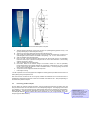
1
ICES Planning Group on Northeast Atlantic Pelagic Ecosystem Surveys (PGNAPES) ICES Planning Group of Temperate International Pelagic Surveys (PGTIPS) MANUAL FOR HYDRO ACOUSTIC SURVEYING IN THE NORTHEAST ATLANTIC !!!!!!! DRAFT ONLY till PGNAPES 2008 Version 2.1 May 2008 International Council for the Exploration of the Sea Conseil International pour l’Exploration de la Mer H. C. Andersens Boulevard 44–46 · DK-1553 Copenhagen V · Denmark Telephone + 45 33 38 67 00 · Telefax +45 33 93 42 15 www.ices.dk · [email protected] !!!!!! Table of Contents 1 INTRODUCTION ..............................................................................................................................5 2 SURVEY COORDINATION ..............................................................................................................6 2.1 2.2 2.3 2.4 2.5 3 Survey planning ............................................................................................................................................ 6 Survey coordinator........................................................................................................................................ 6 Coordinating vessel ...................................................................................................................................... 6 Information exchange ................................................................................................................................... 6 Cruise plan.................................................................................................................................................... 7 SURVEY DESIGN ............................................................................................................................7 3.1 3.2 4 Survey area................................................................................................................................................... 7 Survey implementation ................................................................................................................................. 8 ACOUSTIC SAMPLING .................................................................................................................10 4.1 4.2 4.3 4.4 4.3.1 4.3.2 4.4 5 BIOLOGICAL SAMPLING..............................................................................................................24 5.1 5.2 5.2.1 5.2.2 5.2.3 5.2.4 5.3 6 Sampling plankton ...................................................................................................................................... 28 Processing plankton samples .................................................................................................................... 29 HYDROGRAPHICAL SAMPLING ..................................................................................................30 7.1 8 Trawling....................................................................................................................................................... 24 Biological sampling procedure ................................................................................................................... 24 Total catch treatment ............................................................................................................................ 25 Length measurements .......................................................................................................................... 26 Aging: Collection and reading of otoliths and scales ........................................................................... 26 Maturity stages ...................................................................................................................................... 27 Deepsea species ........................................................................................................................................ 28 PLANKTON SAMPLING ................................................................................................................28 6.1 6.2 7 Mounting acoustic equipment .................................................................................................................... 10 Calibration ................................................................................................................................................... 10 Inter-ship comparison (’Intercalibration’).................................................................................................... 13 Echosounder operation .............................................................................................................................. 14 Operation procedure for Simrad EK500............................................................................................... 14 Operation procedure for Simrad EK/ER60........................................................................................... 15 Interpretation of acoustic images - ”Scrutiny” ............................................................................................ 16 CTD operation............................................................................................................................................. 30 DATA ANALYSIS ...........................................................................................................................31 8.1 8.2 PGTIPS approach....................................................................................................................................... 31 PGNAPES approach .................................................................................................................................. 33 9 CRUISE REPORTS ........................................................................................................................35 9 DATA HANDLING ..........................................................................................................................35 10.1 PGNAPES web based database................................................................................................................ 35 10.1.1 Overview and exchange format........................................................................................................... 35 10.1.2 PGNAPES database table description ................................................................................................. 36 10.1.3 Example of data export from Access.................................................................................................... 36 10.1.4 Internet access to PGNAPES database............................................................................................... 38 10.2 PGTIPS -Fishframe- webbased database ................................................................................................ 39 11 REFERENCES.............................................................................................................................39 APPENDIX A. VESSEL DETAILS..........................................................................................................41 APPENDIX B. ANGLE SENSITIVITY.....................................................................................................44 APPENDIX C. MATURITY CLASSIFICATION FOR HERRING.............................................................45 APPENDIX D. MESH SIZE MEASUREMENTS .....................................................................................48 APPENDIX E. PGNAPES DATABASE FORMAT..................................................................................49 APPENDIX F. PGNAPES DATABASE EXTRACTION CODES ............................................................52 1 Introduction This manual was developed through the ICES Planning Groups on Northeast Atlantic Pelagic Ecosystem Surveys (PGNAPES) and the Planning Group of Herring surveys (PGTIPS) as a guide to the methodologies that should be adhered to during the planning, execution and analysis phases of ICES coordinated survey programs. The results of the surveys discussed in this document are provided in area and time based management units in an attempt to move towards an ecosystem approach in the group. The surveys described here are the following: PGNAPES surveys The first survey within this group is termed the “International blue whiting spawning stock survey”, for the time being and only in this document, further referred to as IBSSS, and aimed at assessing the spawning stock biomass of blue whiting during the spawning season in March-April as well as to determine the spatial distribution at this time of year. This estimate is used as a tuning index by ICES to determine the size of the population. The spawning areas of blue whiting west of the British Isles have most actively been surveyed by Norway and Russia. Some coordination of these survey activities took place over a number of years, until the Russian spawning stock survey was discontinued in 1996. Russia resumed the blue whiting spawning stock survey in 2001. There was, however, no further coordination between Norwegian and Russian surveys. In the Norwegian Sea and Barents Sea the joint survey in late spring (late April-early June) is termed the “International ecosystem survey in the Nordic Seas”, for the time being and only in this document, further referred to as IESNS, aimed at observing the pelagic ecosystem in the area, with particular focus on Norwegian Spring Spawning herring, blue whiting, zooplankton and hydrography. In 2003 ACFM recommended that a coordinated survey be organised covering the main spawning grounds of blue whiting. Other countries than those presently taking part in these surveys were invited to take part. The coordination of blue whiting surveys is taken care of by an extended ICES Planning Group on Northeast Atlantic Pelagic Ecosystem Surveys (PGNAPES), including also the blue whiting spawning survey during spring. PGTIPS surveys The survey targeting the largest stock within this group is the North Sea Hydro Acoustic Survey for Herring and Sprat (HERAS) in July. It traditionally delivers indexes for North Sea autumn- and springspawners spawners and sprat to the ICES Herring Assesment Working Group (HAWG). Closely connected to HERAS is the West of Scotland Herring Survey, which deals with autumnspawners west of Scotland (ICES area VIA) during the same period. Listed in the table below are the contributions since 2004 by country to the surveys coordinated through ICES led PGNAPES and PGTIPS planning groups. Table 1.1. Survey contributions. Country Denmark Faeroe Islands Germany Iceland Ireland Norway Russia The Netherlands France Spain Scotland England IBSSS Expertise Vessel Expertise Vessel Vessel Vessel & Expertise Vessel Vessel Funding Funding Expertise Expertise Survey IESNS Vessel Vessel Expertise Vessel Vessel Vessel Expertise Expertise Expertise HERAS Vessel Vessel Vessel Vessel Vessel - For all surveys mentioned above at least the following research methods are being applied: • Hydro acoustic sampling • Trawl sampling • Plankton sampling • Hydrographic sampling For a more detailed description of the work carried out by the planning groups and to review current reports please refer: PGTIPS (former PGHERS):http://www.ices.dk/iceswork/wgdetailacfm.asp?wg=PGHERS PGNAPES: http://www.ices.dk/iceswork/wgdetailacfm.asp?wg=PGNAPES 2 Survey coordination 2.1 Survey planning The main forum for survey planning are the PGNAPES/PGTIPS meetings the year before the survey. Planning will usually start before the meeting, and continue until the time of the survey. By the time of the meeting, participating countries must decide the resources that they can offer for a survey at the level of detail that allows the group to effectively plan the survey. Details about the resources include: • Vessel(s) • Vessel time (effective survey days) • Possible/impossible dates and areas of operation • Possibilities for sharing expertise through exchange of personnel Based on the available resources for the survey, allocation of survey effort in terms of areas and dates is decided during the PGNAPES and PGTIPS meetings. 2.2 Survey coordinator Survey coordinator should be appointed for each coordinated survey, preferably during the PGNAPES meeting the year before the survey. Survey coordinator then has the responsibility to carry planning further, for example to update the survey plan as more detailed information on commitments becomes available. Survey coordinator is the main contact person for information exchange before, during and after the survey, until finishing the survey report; similarly, survey coordinator must keep other participants updated about the planning. It is also the responsibility of the survey coordinator to find suitable dates and venue for post-survey meeting, if such meeting is arranged. Contact details for survey vessels involved are given in Appendix A. 2.3 Coordinating vessel During the survey, one vessel will act as the coordinating vessel. Usually this will be the vessel where the survey coordinator is. Coordinating vessels is the hub for information exchange during the survey. Contact details for a number of vessels can be found in the table below. A coordinating vessel will be chosen during the survey planning phase. Contact details for survey vessels involved are given in Appendix A. 2.4 Information exchange PGNAPES Data exchange during and after the survey is relatively smooth due to improved adherence to the PGNAPES data exchange format. Further improvements to the data exchange and database format were discussed. It was agreed that proposed changes of data formats will be sent in before the start of the survey in order for all vessels to use the most up to date format for data exchange. An important change in the database format was to switch from common PGNAPES species naming to the use of the standard three-letter species code used by ICES. All 2006 data will be imported into the database shortly and made available for the survey participants on the web. PGTIPS The North Sea – and the West of Scotland survey are coordinated by PGTIPS. Aggregated data survey data are uploaded in the Fishframe database at least a month before the meeting date (normally end of January). During the meeting the joined estimates and the survey report are prepared for the HAWG. The groups is trying to develop a database containing raw international survey data. However regional differences in survey methods, induced by the highly variable circumstances by area, causes the process of raising the data to aggregated level to be different. Thus the data collected in the different national areas are not compatible and the national participants do not give a high priority to the upload of raw data (which is complicated anyway), knowing that they will have to be dealt with separately anyway. At PGTIPS the coverage for the July surveys are planned. During the surveys there is daily radio contact between the national vessels. 2.5 Cruise plan An annual cruise plan requires at least the following items: • Expertise needed during the survey o Scrutiny o Fish taxonomist o Oceanographer (technical, interpretation) o Acoustic technician (calibration, operation) o IT technician (Unix, windows, Ingres, network) • Trajectories to be survey • Stations to be sampled (CTD, Plankton) • Additional sampling requirements • Coordination between vessels • Deadlines for (partial) data results and reports 3 Survey design 3.1 Survey area PGNAPES IESNS (to be updated by PGNAPES members) IBSSS In 2004–2005, PGNAPES produced a plan for achieving the optimum coverage that could be achieved for the spawning area blue whiting surveys. This plan was followed in the surveys in spring 2005 and 2006. Based on experiences gained, the overall timing of the survey (from mid-March to mid-April) appears appropriate, although a further review of coordinated survey timing is undertaken each year. The spatial confines of the survey, although not fixed, are defined as core spawning areas and secondary target areas as suggested in 2005 (Figure 3.1). Every year the target areas will be allocated to ships, but the highest priority will always be target area 1 (this area has usually hosted about half of blue whiting biomass in the survey area). The survey must follow the standardised survey protocol given in this report. I. Barent Sea II. Central Norwegian Sea III. Icelandic Zone I. II. III. IV. V. South Porcupine North Porcupine Hebrides Southern Faroese Rockall and Hatton Banks Figure 3.1. Survey sub-areas used in the IESNS and IBSS PHTIPS The international area of the North Sea Hydro Acoustic survey is every year the same, based on where herring and sprat have been found historically. The survey is roughly divided in 5 national areas (see figure below). These areas may be different from year to year for logistic reasons, but also to get to know each others border area, sometimes overlap and inter calibrations. The survey effort is basically two east-west transect through each ICES rectangle, However high density area are covered with a double intensity at the cost of areas with low concentrations (see figure 3.2). A B Figure 3.2. A: Survey area layouts for all participating vessel in the 2008 acoustic survey of the North Sea and adjacent area’s. (IE = Celtic Explorer; WSC = West of Scotland charter; SCO = Scotia; NOR = Johan Hjort; DK = Dana; NL = Tridens; GER = Solea). B: Figure … Survey effort in the 2008 acoustic survey of the North Sea and adjacent areas. (Red = 7.5 nautical miles spacing; Magenta 15 n. mi.; Cyan = 30 n. mi.). 3.2 Survey implementation Transect design Area coverage Pre-agreed target area coverage is designed to maximise survey effort and avoid duplication. It is dependent on the pre-agreed survey areas as assigned during the survey planning phase and should be adhered to wherever possible. Agreement: Variations from pre-agreed target areas should only be undertaken after consultation with the assigned survey coordinator. Orientation This is specific to the type of survey being undertaken. Two aspects should be considered in choosing the direction of transects. Transects should preferably run perpendicular to the greatest gradients in fish density, which are often related to gradients in bottom topography and hydrography. This means that transects will normally run perpendicular to the coast. The second aspect considers the direction in which the fish are migrating. If there is evidence of rapid displacement of the fish throughout the area, it is advisable to run transects parallel to the direction of migration. This survey design will minimise the bias caused by double counting. PGNAPES note: For IBSSS: The survey direction is historically from south to north which is NOT in opposition to the known migration patterns. Since inter-vessel time gaps can be as much as several weeks either survey direction would lead to a bias in the stock distribution and stock estimate and therefore it was decided to continue the historical approach. However, a strong effort has been made in 2007 to compress the overall survey time window to avoid double counting. PGTIPS note: For HERAS: The northern North Sea is survey in a south-north direction while the centre and southern North Sea are surveyed in a north-south direction. A detailed simulation study of the effects of motion on the survey design of North Sea herring is available in Rivoirard et al. (2000). Design PGNAPES: Due to the extent of geographical coverage carried out during the IBSSS, a parallel transect design has been adopted during this survey. Based on a review carried out by Rivoirard et al., (2000), as referred to by Simmonds and MacLennan (2005), in instances where transect length is twice that of transect spacing a parallel design should be used as the best means of reducing variance. Spacing • PGNAPES - Transect spacing as agreed during the PGNAPES survey planning phase should be no less than 30nmi or no greater than 40nmi where possible to maintain the integrity of the international time series. • PGTIPS - Transects are spaced at a maximum distance of 30 nautical miles and a maximum distance of 7.5nautical miles. Survey progression in time It should be carried out as determined during the survey planning phase (PGNAPES, PGTIPS) and adhered to wherever possible. Live communication with the survey coordinator is essential. Contact details for survey vessels involved are given in Appendix A. Ship’s speed During the survey speed should be maintained at 10–12 knots where possible. At higher speeds, problems are encountered with engine noise or propeller cavitation. These problems, however, depend on the vessel and the positioning of acoustic transducers. In rough weather, the ship’s speed may be reduced as required in order to avoid problems with air bubbles under the ship and resultant loss of signal, although this problem is somewhat alleviated by the use of a dropped keel mounted transducers. Acoustic recording depth PGNAPES: Is set to 750 meters. No blue whiting or herring is expected to be at greater depths. PGTIPS: Is set to the bottom for North Sea surveys. To be updated by PGTIPS members. Day/night operations It is recommended – if time permits during the survey – to study the diurnal behaviour of fish schools, in order to determine at what time during the 24hr period the fish may not be available to the echosounder. Listed below is the current survey operand: • PGNAPES - 24 hour operations • PGTIPS - During North Sea West of Scotland and Irish herring surveys operations are conducted during the hours of daylight in the areas covered by the German, Dutch, Scottish and Irish vessels. Surveys in the Danish and Norwegian areas are executed according to a 24 hours scheme. 4 Acoustic sampling 4.1 Mounting acoustic equipment Transducer The standard transducer used in fisheries acoustics is the 38kHz ES38B from Kongsberg Simrad. In order of preference, it is advisable to mount the transducer in a dropped keel, a towed body or on the hull of the vessel. Steps should be taken to ensure that the flight of the towed body is stable and level, this should ideally be achieved with the aid of a motion sensor. Drop keel mounting Modern research and certain commercially chartered vessels are now equipped with a retractable drop keel on which acoustic sensors may be mounted (Figure 4.1). Figure 4.1. Drop keel mounting (left panel) and difference in performance with hull mounting (right panel). Source: http://www.uib.no/gosars/english/background/special_features/dropkeel_more.html Towed body mounting A tow body is an independent towed unit suspended from the main survey platform with a mounted transducer (Fig. 4.2). As the unit is towed alongside the vessel the survey depth is a function of cable length and vessel speed. Figure 4.2. Towed body as used by FRS Aberdeen and IMARES (left panel) and image of a typical towing depth (right panel). Source:http://www.acoustics.washington.edu/~gauthier/Research/Sitka/towfish1.jpg 4.2 Calibration There are a number of transducer parameters that require knowledge of the sound speed in water. The theoretical context is given in Bodholt 2002. It is essential that a CTD cast is used to determine the temperature and salinity of the water so that sound speed can be calculated (see Appendix 2 and MacLennan & Simmonds 2005 for equations) and entered into the EK500 or the EK/ER60. Calibration of the transducer should be conducted at least once during the survey. Calibration procedures are described in the Simrad EK500 manual, the EK/ER60 manuals and by Foote et al. (1987). Ideally, the procedure as described in the Simrad manual should be followed with certain exceptions (see below). Minimum target range for the calibration of a split beam 38 kHz echosounder is 10 metres, although greater distances are recommended (about 20 m), because centering of the target below the transducer is facilitated if the target is suspended at a greater depth. An average integrated value for the sphere, taken when it is centrally located, should be taken as the measured NASC. The calculations should be then performed a number of times (two or three) in an iterative procedure such that the values of measured NASC and theoretical NASC should converge, as described in the Simrad manual. A choice is then made as to whether the Sv Transducer gain should be changed, rendering absolute NASC, or alternatively, the Sv Transducer gain can be unaltered and a correction factor applied to the NASC. Only one strategy should be applied during a cruise, such that for example, the latter option is to be employed when calibration is only possible after the cruise has started. If possible, the transducer should be calibrated both at the beginning and the end of the survey; with a mean correction factor applied to the data. If a new calibration differs less than 0.2 dB, the sounder system functions acceptably. If it differs more than 0.2 dB, the system should be thoroughly inspected. There are a number of parameters which require knowledge of the speed of sound in water. It is therefore recommended that appropriate apparatus be used to determine the temperature and salinity of the water so that sound speed can be calculated (see MacLennan & Simmonds 1992 for equations) and entered into the EK500 or the EK/ER60. A number of calibration parameters and results (tabulated in the table below) should be included as a minimum in the final survey report. Some of these parameters not included in the Simrad operators manual and are defined below and will be specific to certain operating systems only. 4.2.1 Calibration procedure for Simrad EK/ER60 echosounder The calibrating procedure for the Simrad EK and ER60 are clearly laid out in the users manual and should be followed as such. The determination of sound speed for the ER60 is calculated automatically in the environment dialogue box, when the parameters of temperature and salinity are inputted from CTD casts. During the actual calibration itself, Simrad recommend no less than 150 data points from the standard target sphere per frequency. Outlying points above or below the target reference TS value can be removed as required to further refine the accuracy of the result before final acceptance of the data set. Updating the beam pattern is the final stage of the calibration procedure and will result in an alteration of the beam pattern parameters. The Simrad ER60 allows the beam pattern to be adjusted by loading the results of previous calibrations if erroneous values are entered by mistake. A calibration report for all survey calibrations should be included in the final cruise report. Caution! Before starting a calibration make sure that the transducer has been given time to adjust its temperature to the surrounding water temperature. The absorption coefficient on the EK/ER60 can be set to 1 decimal place. Calculations using Temperature of 10.5 degrees, salinity of 34.5 ppt depth of 60m, ph 7.5 gives an absorption of 9.8dB/km at 38kHz (from Echoview calculator using Francois and Garrison (1982) formula). The angle sensitivity can be found in Install/Transceiver installation/Transducer parameters. The LOBE program or a similar program should be used for calibration. Calculations concerning angle sensitivity can be found in Appendix B. The transducer settings of the EK/ER60 can be found in Install/Transceiver installation/Transducer parameters. To get the calibration report from EK/ER60 : Open the calibration program: C:\Program Files\Simrad\Scientific\EK/ER60 \Bin\Calibration.exe Open the file created with the calibration of your primary transducer and Print as .PDF gives you the possibility to have the first part of the file, containing calibration settings and results as an image in stead of a table. The format is fixed and it can be used in reports easily. 4.2.2 Calibration procedure for Simrad EK500 echosounder It is evident that all versions of the EK500 up to and including version 5.* do not take account of the receiver delay in the calculation of target range (see Fernandes & Simmonds 1996). This is particularly important when calibrating at short range (10 m) as it can lead to a systematic underestimate of biomass of 3%. The correct range to the target should therefore be applied in calibration (see below). The equivalent two way beam angle (ψ) should also be corrected for sound speed according to Bodholt (1999). Receiver delay, ∆t: This is very specific mainly to the echosounder band-pass filters and to a lesser extent to the transducer bandwidth, the standard target and the pulse duration which may affect the peak value. Target, bandwidth and pulse duration specific values for the Simrad EK400 are given in Foote et al. (1987, their Table 1). Values for the EK500 can be measured. Bethke (2007) provided a result for the narrow bandwidth. For the wide bandwidth (3.8 kHz) Simrad recommends using 3 sample distances (10 cm). This equates to a value: ∆t = 1.07 ms for narrow bandwidth (∆r = 0.8 m) ∆t = 0.39 ms for wide bandwidth (∆r = 0.3 m) The range to half peak amplitude, rm: This is the measured range between the start of the transmit pulse and the point on the leading edge of the echo at which the amplitude has risen to half the peak value (m). This is usually determined from experience with the readings from an oscilloscope display. For example, for a 38.1 mm tungsten carbide standard target insonified at 38 kHz at a colour Threshold setting of -70 dB (Sv colour min.), it is measured as from the top of the transmit pulse to the leading edge of the pink colour on the target sphere echo. However, range to sphere = rsph may then be calculated to verify the measured results: rsph = rm − ∆r = rm − c × ∆t 2 Note that in the firmware version 5.2 and 5.3 a correction of 3 samples is already included. A simple check can be carried out. Two calibrations at the same environmental conditions but at different ranges have to show the same results. Correction factor for pre-calibration NASC’s on EK500: 1 K= ∆G 10 5 Where: ∆G = Calibrated Sv Transducer Gain – Default Sv Transducer gain Correction factor for pre-calibration Sv’s on EK: K = 10 log10 ( sAcorrection factor ) A calibration report as shown in Tale 4.1 should be completed at the end of each calibration . Calibration report Frequency (kHz) Transducer serial no. Vessel Date Place Latitude Longitude Bottom depth (m) Temperature (°C) Salinity (ppt) Speed of sound (m.s-1) TS of sphere (dB) Pulse duration (s) Equivalent 2-way beam angle (dB) Receiver delay (s)* Default Sv transducer gain Iteration no. Time Range to half peak amplitude (m)* Range to sphere (m) Theoretical NASC (m2.nmile-2) Measured NASC (m2.nmile-2) 1 2 3 1 2 3 Calibated Sv transducer gain DeltaG = New gain - Old gain Correction factor for pre-calibration NASC's on EK Correction factor for pre-calibration Sv's Default TS transducer gain Iteration no. Time Measured TS Calibrated TS gain Table 4.1: Calibration report sheet used with EK500 calibration Note:* All parameters may not be necessary when using the Simrad EK/ER60 echosounder. 4.3 Inter-ship comparison (’Intercalibration’) The advantage of inter-ship comparison is that it will demonstrate any gross difference in acoustic performance. The inter-ship comparison is NOT an absolute calibration, but it is a useful means of checking that there is no great difference in the respective measurement capabilities, which might occur for instance if one vessel suffered more fish avoidance due to having a worse noise signature, and thus consistently indicated a lower abundance for the same fish ensemble. If the comparison nevertheless reveals a large difference, the equipment on both ships should be recalibrated as soon as possible, in accordance with the procedures described in section 4.2. The inter-ship comparison works best when: • It is done in an area where there are substantial quantities of fish in layers, or dispersed aggregations of varying density. • Moving in formation (figure 4.3), keeping around a 400m offset astern not being in each others wake not detecting the other vessels’ echosounder taking the lead in turns in case one ship is more sensitive to weather or avoidance behaviour than the other. • Covering a time window of 2-6 hours depending on the spatial distribution and density of fish in that area • Keeping constant radio contact to ensure satisfactory cooperation Figure 4.3. Typical inter-vessel comparison track lines where both vessels take the lead position in turns. Integration periods need to be synchronized so that they relate to the same portion s of the cruise track. Thus the following ship must record the echo-integrals over time periods which are delayed relative to those of the leader. Keeping track of the log counter of the default way to do this. Treatment of results Standard Ricker regression techniques are used in data analysis (see the figure below). These procedures are available within PGNPES as R codes. If the 95% confidence limits do not include unity, as in the example below this suggests that one ship is producing biased results and the reason for this discrepancy should be investigated. Figure 4.4 Results from an inter-vessel comparison ‘vessel A‘ against ‘vessel B’. The regression slope is 0.56 showing a significant difference between the vessels. The upper panels show sequential data along the cruise track, the lower panels are scatter plots comparing concurrent measurements on the two vessels. (The left panels show original values whereas the right panels show these same values on a log scale. 4.4 Echosounder operation There are a number of settings that are made during calibration that have a direct influence on the fundamental operation for echo-integration and target strength measurement and therefore affect logged data. Once set according to the particular transducer these should NOT be changed during the survey. It is recommended that each year the same settings be used for the survey in order to facilitate comparison across years. 4.3.1 Operation procedure for Simrad EK500 Apart from the settings obtained during the calibration for most settings the default values from the manufacturer may be used, or alternatively the operator can choose his own settings depending on the circumstances. It is recommended that each year the same settings be used for the printer in order to facilitate comparison of echograms. The settings changed by the calibration have a direct influence on the fundamental operation for echointegration and target strength measurement and therefore affect logged data at stable environmental conditions. Once set according to the particular transducer, these should NOT be changed during the survey. These important settings are listed in Table 4.2. The minimum detection level on the bottom detection menu depends on the water depth and bottom type. At depths less than 100 m and hard bottoms, the Threshold level may be set at –30 dB: this will enable the instrument to detect dense schools close to the bottom. At depths greater than 100 m or soft bottoms, the Threshold has to be lowered (-60 dB), otherwise the upper layer of the bottom will be counted as fish as well. However, misinterpretation can be repaired by the operator during the scrutinising procedure. In the operation menu it is recommended to use as short a regular ping interval as possible. It is not advisable to use a ping rate of 0.0 seconds (variable interval according to depth) as this brings about irregular sample (ping) numbers per equivalent distance sampling unit which may bias the analysis with the EchoView program. A bottom margin of the order of 0.5 m is recommended for the layer menus. In shallow areas (<100 m) this can be somewhat reduced. The Sv minimum for echo integration and presentation of the echogram should be set at –70 dB. Increasing the Sv minimum will reduce the integration values if the herring occur in scattering layers or in loose aggregations. This setting is less important when the data is collected by a post processing package such as Simrad’s BI500 or Sonardata’s EchoView software as the Threshold can be determined in post processing. Users were asked to compile a list of variables that must be held constant to maintain comparable survey conditions. Table 4.2. Important calibration and survey settings for the EK500, which should not be changed during the survey. Those marked * indicate settings that are specific to the transducer / transceiver. /OPERATION MENU/Ping Mode /OPERATION MENU/Ping Interval /OPERATION MENU/Transmit Power /OPERATION MENU/Noise Margin /TRANSCEIVER MENU/Transceiver-1 Menu /TRANSCEIVER MENU/Transceiver-1 Menu/Transducer Type* /TRANSCEIVER MENU/Transceiver-1 Menu/Transducer Depth /TRANSCEIVER MENU/Transceiver-1 Menu/Absorption Coef. /TRANSCEIVER MENU/Transceiver-1 Menu/Pulse Length /TRANSCEIVER MENU/TRANSCEIVER-1 MENU/BANDWIDTH /TRANSCEIVER MENU/TRANSCEIVER-1 MENU/MAX. POWER* /TRANSCEIVER MENU/TRANSCEIVER-1 MENU/2-WAY BEAM ANGLE* /TRANSCEIVER MENU/TRANSCEIVER-1 MENU/SV TRANSD. GAIN* /TRANSCEIVER MENU/TRANSCEIVER-1 MENU/TS TRANSD. GAIN* /TRANSCEIVER MENU/TRANSCEIVER-1 MENU/ABSORPTION COEF.* /SOUND-VELOCITY MENU/PROFILE TYPE /SOUND-VELOCITY MENU/VELOCITY MIN /SOUND-VELOCITY MENU/ VELOCITY MAX /TRANSCEIVER MENU/Transceiver-1 Menu/3 dB Beamw.Along* /TRANSCEIVER MENU/Transceiver-1 Menu/3 dB Beamw.Athw.* /TRANSCEIVER MENU/TRANSCEIVER-1 MENU/ANGLE SENS.ALONG* /TRANSCEIVER MENU/TRANSCEIVER-1 MENU/ANGLE SENS.ATHW.* /TRANSCEIVER MENU/TRANSCEIVER-1 MENU/ALONGSHIP OFFSET* /TRANSCEIVER MENU/TRANSCEIVER-1 MENU/ATHW.SHIP OFFSET* Table 4.3. Settings for the EK500, which could be changed (*if the environmental condition change) /OPERATION MENU/Noise Margin /TRANSCEIVER MENU/Transceiver-1 Menu/Transducer Depth /TRANSCEIVER MENU/Transceiver-1 Menu/Absorption Coef.* /TRANSCEIVER MENU/TRANSCEIVER-1 MENU/2-WAY BEAM ANGLE* /TRANSCEIVER MENU/TRANSCEIVER-1 MENU/SV TRANSD. GAIN* /TRANSCEIVER MENU/TRANSCEIVER-1 MENU/TS TRANSD. GAIN* /TRANSCEIVER MENU/TRANSCEIVER-1 MENU/ABSORPTION COEF.* /SOUND-VELOCITY MENU/VELOCITY MIN* /SOUND-VELOCITY MENU/ VELOCITY MAX* /TRANSCEIVER MENU/Transceiver-1 Menu/3 dB Beamw.Along* /TRANSCEIVER MENU/Transceiver-1 Menu/3 dB Beamw.Athw.* /TRANSCEIVER MENU/TRANSCEIVER-1 MENU/ANGLE SENS.ALONG* /TRANSCEIVER MENU/TRANSCEIVER-1 MENU/ANGLE SENS.ATHW.* /TRANSCEIVER MENU/TRANSCEIVER-1 MENU/ALONGSHIP OFFSET* /TRANSCEIVER MENU/TRANSCEIVER-1 MENU/ATHW.SHIP OFFSET* 4.3.2 Operation procedure for Simrad EK/ER60 The following steps should be checked: Settings in header menu: Install /Transceiver 1. Check if all frequency channels appear in green text. If not, choose correct transducer in “transducer/selection”. /Navigation 1. Select serial port of GPS device. If nothing present or other, check “port management” in Install – port control. 2. Select serial port of speed information (probably GPS) 3. Select distance calculation method (probably from speed). This box is also used to set the starting number of the overall distance of the survey. /Environment 1. Set the temperature and salinity of the calibration site Output file 1. Directory: enter data recording directory 2. Raw data/file size: decide on the length of individual datafiles (based on distance or file length) Operation normal 2. Mode: active 3. Set pulse duration, sample interval bandwidth combination. This pulse duration should be equal to the one used in the calibration file. 4. Choose power which to use 5. Set depth of transducer from surface level Operation ping control Choose a ping interval which does not give an error or warning. Input of calibration data After completing the above steps you should now be able to view correct echograms of the installed frequencies. Right click on the single echo window which opens the single target detection dialog. Then click “calibration”. In the calibration window, open the calibration file made during calibration. Click “update beam data” to upload calibration data into the echosounder. The echosounder should then be ready for use. 4.4 Interpretation of acoustic images - ”Scrutiny” The process of echogram scrutinisation is a largely subjective process that should be at the very least carried out in the presence of someone who is experienced not only with the process but also with the survey area and the target species. Species aggregation tactics may vary greatly between species in addition to temporal and geographical variation. As a result the allocation of NASC to species always needs support of trawl-information. However, it should be noted that catch composition is influenced by the fish behaviour in response to the gear. It is therefore necessary to judge whether the catch-composition is a true reflection of the real species composition of the logged school or layer data and whether the allocated percentage species composition needs to be further investigated. An effort should be made to scrutinize to the species level, where possible, and adhering to ICES threeletter species codes for data submissions. Probability classifications are being used in the North Sea herring survey (“definitely”, probably”” and “possibly” classes). During mixed species analysis e.g. during coastal surveys, if it proves impossible to accurately determine mixed species aggregations to species level then mixed ‘codes’ should only be submitted to the group through prior agreement. Methods of species allocation are often highly specific to the survey being undertaken. The method used depends largely upon the schooling behaviour of the target species, and the mixing with other species. For example: In the North Sea and Division VIa the species allocation is based mainly on the identification of individual schools on the echogram. In the Skagerrak-Kattegat and Baltic the identification is based on composition of trawl catches. A few typical target species echograms are shown below. It is obvious that during the scrutinising process subjective decisions have to be made. However, joint sessions of scientists from participating countries who scrutinised each others data has shown that the deviation between the estimated quantities of herring are within the range of 10%, provided that trawl information of the recordings is available (Reid et al. 1998). The scrutinizing is based on combination of visual clues in the echograms, information from single echoes, disappearance of echoes when changing lower integration Threshold, trawl catches, and possibly comparing echoes from different frequencies. This is an expert process prone to errors and subject to a large degree of subjectivity. Often it is useful to look observations over some tens of miles at time, as some continuity that facilitates scrutinizing can usually be expected. Through a process of personnel exchange on surveys and dedicated workshops it is hoped to further develop the existing knowledge base within both PGNAPES and PGTIPS on fish behavior directly relating to echogram scrutinisation. Echogram scrutinisation used to be done by measuring the increment of the integrator line on the printed paper output of the echogram. This was a simple and efficient way of scrutinising if one deals with single species schools and if there are no problems with bottom integration. More generally, computer based post-processing systems such as the Simrad BI60 or Sonardata Echoview systems are currently being used for scrutinising. It is recommended that one depth-range be used for the whole area in the printer output and on postprocessing systems. This will ensure that similar echo traces from all parts of the survey area will have the same appearance and hence are visually more comparable. For all internationally coordinated surveys, a range of ICES three letter species codes have been applied through a common database to ease the flow of data between participant countries. Use of trawl information The allocation of echo-traces to species is governed by the results of trawl hauls. In many cases these are considered together with observations from the netsonde and the echogram during the haul. In some cases it is not possible to assign schools (echo traces) to species directly e.g. where the haul contains a mixture of species and no clear differentiation can be made between the observed schools. In such situations the integral is assigned to a species mixture category according to the trawl results. This is defined as percentage by number or weight taking into account the correct conversion to scattering length; post processing software is then used to apply weights and lengths. There are two main problems with using trawl data to define “acoustic” mixtures: • • Different species are known to have different catchabilities when encountering fishing gear, so the exact proportions in the trawl are unlikely to be an exact sample of the true mixture. For instance herring are likely to be faster swimmers than blue whiting. • PGTIPS: For instance herring are likely to be faster swimmers than Norway pout A target species may also be encountered within a multi-species mixed layer. In some instances the non-target species may be small enough to pass through the gear meshes, thus providing a bias in the trawl catch to the actual content of the school/layer. Mesh size calculations are given in Appendix D. • PGTIPS: Herring are often found in a mixture with “0” group pout, which are mostly lost through the meshes. This may also occur with other small gadoids. In this case the exact proportions are unavailable and the operator must make an informed guess Target species specifications Herring (Clupea harengus) and Sprat (Sprattus sprattus) Remarks: In the western and northern part of the area covered by the survey, most of the herring occur in welldefined schools, often of a characteristic shape as pillar-shaped large dense schools or as layers of very small and dense school at the surface. In the northern and central part, schools of Norway pout and herring are difficult to distinguish from each other. In low density areas of the western area mixed layers and aggregation of small schools consisting of gadoids and herring may occur. Sprat marks in the North Sea and VIa appear mostly as quite large, typical, pillar-shaped marks, usually slightly more diffuse than herring and usually in shallow water. Examples of typical echograms: Comment [sy1]: We could decide to leave examples out. Distinct - Northern North Sea Scattered and mixed - German Bight Surface layer - Norwegian Sea (IESNS). Threshold: -80dB. Blue whiting (Micromesestius poutassou) Distinct layers – West of British Isles (IBWSSS). Threshold: -70dB. Remarks: Fluffy schools to layers - Norwegian Sea (IESNS). Threshold: -70dB. Sandeel (Ammodytes marinus, Ammodytes tobianus) 38 Khz echogram (left panel) and the 200 kHz echogram (right panel) in the North Sea herring spawning survey. Threshold: -70dB. Meso-pelagics Remarks: Meso-pelagic fish species is a name often used for all unidentified backscatter layers in deeper waters (300m – 750m) not likely to be plankton. Examples of typical echograms: Krill Mackerel (Scomber scombrus) Remarks: Mackerel will hardly be detected by the 38kHz transducer but will lit up weak on the 200kHz. Examples of typical echograms: Horse mackerel (Trachurus trachurus) Examples of typical echograms: Description: Pearlside (Maurolicus müelleri) Examples of typical echograms: Description: Software post-processing procedures Echoview software post-processing procedures General checklist: 1. Put selected template in Echoview template folder. 2. Create new EV file selecting the correct template (if one may exist for this type of survey). All species names, virtual variables used and other settings will be copied from this template. 3. Add datafiles. Tip: create an Echoview file not containing too much raw data files (e.g. one day fileset). Tip: open cruisetrack for first check. Just check to see if cruise track is in the correct place and no files are missing. If not this might be due to freak start so add extra file at the beginning of file set. 4. Save as, using cruise and daily file name, into a logic directory structure. 5. Update calibration settings in all frequencies to be used. Check if this is set to automatically”. 6. Block out bad data (define analysis area). Tip: open cruisetrack while blocking out bad data. Minor bottom integrations can cause a huge amount of unwanted biomass. Potential sections to block out: • Period with no daylight. • All trawling activity. The restart position can be estimated in the Cruise Track Window, where the track crosses start position on restarted survey. Any other periods not to be included such as extra stations, steaming periods or sections between transect. 7. Assign bottom and surface lines (below bottom and entire near field need to be blocked out). For a standard 38kHz near field is set to approximately 7m. 8. Scrutiny (see below) 9. Check export settings (if not already in the template) and export LSSS software post-processing procedures BI500/BI60 software post-processing procedures Thresholding remove unwanted echoes and keep target species An advantage of using a post-processing systems like BEI or EchoView is the ability to change the Threshold value of the received echoes. By changing the Threshold the non-target-species (plankton in particular) can be filtered out. The Threshold used may differ, depending on a variety of conditions, including the water depth (more care should be taken at greater depth) and the particular size of fish. Examples of conditions where certain Thresholds have been applied using the BEI and Echoview post processing systems are described below; they should not be used without verification. Several institutes have developed or contributed to image processing systems for post processing of echograms. This can extract a range in school descriptors; energetic, morphometric and positional, which can be used to define the characteristics of schools of a particular species. These techniques are based on a license module called “Virtual echogram” often accompanied by the “School detection” module. In general such systems can differentiate most observed schools to species; however, these are usually the schools which an experienced survey operator can also discriminate by more traditional methods. These systems are likely to become more valuable in the future when they can be fed with multi-frequency data. At the beginning of the survey it is advisable to experiment to find the right Thresholds specific to the conditions encountered during the survey. This can be achieved by isolating schools and changing the Threshold to leave only the target species. Notes should be made to track the action taken specific to each survey. Thresholding using the BEI post processing system The main principle has been to use as little threshhold as possible at any time, but experience show that for herring down to approximately 50 meters about -60db is suitable. However, at extremely high levels as experienced in coastal waters a Threshold of up to -54 db maybe required in order to remove unwanted plankton. When starting a new 5-mile, first a layer is entered which defines the lower depth of the vertical herring distribution. This depth is found by looking for herring schools as discrete jumps in the integrator line and include the lowest school. We then set the Threshold at a level where all the plankton is removed. This is done by varying the Threshold and looking for changes in the coloring of the upper level. Herring schools will often appear as very tiny red dots, size only a few pixels, hardly visible. Note that this Threshold applies only for the upper channel, down to approx 50 meters. A note is made of the NASC when the correct Threshold is found. This value is noted and is given to herring after the Threshold has been reduced again to -85 db. The Threshold is lowered again to -85 db, herring is given the noted value and the rest, up to 100 % is given to plankton In deeper waters (below 50m), the procedure for this depth is similar as for the upper layer: The Threshold is reduced until the plankton disappears from the screen, normally till about 69db, sometimes as low as -66db. That NASC is kept for blue whiting and mesopelagic fishes. Normally 20-30 percent is given to mesopelagics and the rest to blue whiting, depending on the ration in the nearest trawl hauls. The rest, up to 100 % is then given to plankton. During blue whiting spawning stock surveys, plankton can filtered out using –82 dB as the reference Threshold level below which all increase in backscattering is assumed to come from targets of no interest. When increasing the Threshold, one expects plankton and mesopelagics to disappear, usually around –69/66/63 dB, unless these are very dense. As a rough rule of thumb, if one has a registration that contains blue whiting and that does not coincide with dense plankton / mesopelagics registrations, proportion of NASC that remains when the Threshold is increased to –66 dB can allocated to blue whiting. However, further adjustment may be applied if there is evidence that registrations contain further non-blue whiting echoes, especially in deeper layers where echoes may get cluttered. If small individuals of blue whiting are present, a lower Threshold may be appropriate. Thresholding using the BI60 post processing system PGTIPS In stratified waters (mainly in the northern - and northeastern part of the survey area) there is often a layer of plankton in the upper 50 m. In this layer, very small, dense schools of herring may be found. Normally all the plankton is filtered out at –42 dB. The remaining NASC may be assigned to herring if clear schools are still visible and, of course, trawl information indicates that herring are present. In the range of 30–60 m the same procedure may be used. Here NASC are normally assigned to schools of fish after filtering out plankton by putting the Threshold in the range of –48 to –51 dB. In the layer below 60 m a Threshold of –54 to –60 dB may be applied. In the deeper parts of the area (>150m) a lower Threshold than –60 dB may be applied. At these depths, often close to the bottom, herring schools are normally, larger and easier to recognize. After scrutinizing, the whole analysis area can be allocated to “plankton and fish” in order to define “plankton” after subtracting the individual regions (fish). Also this method will give you the opportunity to have all surveyed cells in your output files. Multi-frequency use The echosounder frequency routinely used for abundance estimation is 38 kHz. However, many vessels now operate multiple transducers with working frequencies of 18, 120 and 200 kHz. At present these data are used more for species recognition than for abundance estimation. For instance, herring and mackerel may have different target strengths at different frequencies. Mackerel is backscatter more strongly visible at 200 kHz than at 38 kHz (Fig. 4.5). 38 kH z Stronger at 38 kH z 200 kH z Stronger at 200 kH z Figure 4.5. Echogram showing example of multi-frequency approach. To process the data for extraction of schools the variable computation method available in Echo View is being used by many labs. The method has been used in 2001–2003 and was developed under the EU program SIMFAMI. Previously when processing by hand (2000 and before) a small ‘background’ value for scattered fish was removed from integrator layers with many fish schools. It was noted that fish schools appear consistently on 38, 120 and 200kHz echograms while other features such as plankton may be strong on some frequencies and weak on others. Use of single target TS distribution data The SIMRAD EK500 or EK/ER60 used with a split-beam transducer allows the collection of TS values for all single targets detected in the beam. A TS distribution can then be produced for each EDSU. In some situations there may be two species present in an area with substantially different TS values, and this could be used to determine the species allocation. Again, this data must be used with caution. There are doubts about the precision of the TS detection algorithm, particularly in older firmware releases. By definition, single targets are unlikely to be detected from fish in schools. As schools are often the main subject for herring acoustic surveys, TS data may be unrepresentative for the population. However, where the survey encounters diffuse mixtures, there may be value in such data. PGNAPES During blue whiting spawning stock surveys, TS distribution is often useful in separating blue whiting from mesopelagics in the upper layers. If blue whiting is present, one usually expects to see a prominent peak somewhere around –35 dB. Allocation to mixed layers or mixed schools Sometimes fish occur mixed with other species in aggregations of smaller schools. In this case, species allocation is based on the composition of trawl catches. Those schools are separated from other fish using the standard scrutinising procedures (see above) and/or the allocation of the proportion of the different target species on the basis of catch composition. Important! The weight-based catch composition does not always resembles the acoustic image of the schools/layers targeted. See an example below. Table 4.3. Catch composition in kilograms converted to catch composition in sA values. The sA correction factors are taken from Simmonds and McLennan 2007. Catch composition sA correction fctor (kg) (Simmonds &McLennan 2007) sA Catch composition (sA) Whiting 10.0% 1 0.100 37.34% Herring 40.0% 2.4 0.167 62.23% Sandeel 50.0% 426.6 0.001 0.44% Total 90.0% 0.268 100.00% PGNAPES This procedure is normally not applied during the PGNAPES surveys but can be used if necessary. 5 Biological sampling 5.1 Trawling Proper species allocation of the acoustic records is not possible if no trawl information is available. The general rule is to make as many trawl hauls as possible, especially if echo traces are visible on the echosounder after a blank period. If surface schools are known to occur in the area it is often advisable to take occasional surface trawls even in the absence of any significant marks. The principal objective is to obtain a sample from the school or the layer that appears as an echo trace on the sounder by means of directed trawling (figure 5.1). The type of trawling gear used is not important as long as it is suitable to catch a representative sample of the target-school or layer. Gear details for survey vessels involved are given in Appendix A. Figure 5.1 Schematic overview of how to shoot the gear when back trawling. Information about the most important dimensions of the trawls used should be included in the survey report from each of the participating vessels. During trawling it is important to take note of the traces on the echosounder and the netsonde in order to judge if the target-school entered the net or if some other traces contaminate the sample. It is recommended that notes be made on the appearance and behaviour of fish in the net during every haul. If a target is missed during a haul, the catch composition should not be used for species allocation. 5.2 Biological sampling procedure The first step of trawl catch anaylsis is to determine species composition. This can be carried by breaking the total catch into species components by weight either by exhaustive sampling, sub-sampling (raising to the total catch) or by a combination of both. Second step is to record biological parameters of the target species within the catch (age, sex, sexual maturity and individual weight measurements). Table 5.1. Sampling levels for all target species. O=otoliths, S=scales, L=length, M=maturity, G=gender. Sprat Blue whiting Herring Dealfish Mackerel Horse mackerel Snake pipefish IBSSS IESNS HERAS PGTIPS West of Scotland herring survey PGTIPS West of Scotland herring survey (Irish) PGTIPS PGNAPES PGNAPES OLMG LMG L L LG OLMG SLMG LMG L L LG OLMG OLMG L L LG OLMG OLMG L L LG OLMG OLMG L L LG 5.2.1 Total catch treatment The Condition and Quality of the catch should be recorded by the person in charge of the biological sampling in consultation with the officer in charge or the fishing master according to a standard classification (Table 5.2). Condition: Quality: Inspecting the gear when it comes back on deck. Observe how the fishing was carried out and how the gear performed. Table 5.2. Condition and quality categories. Condition Condition of the gear after the haul is finished Not inspected No damage or minor damage of the gear, nothing of consequence to selection and catch. Gear is damaged. Some fish may have escaped the codend. Trawl has long gashes, or large pieces of net are missing, codend intact. Codend torn, very little catch. Codend torned, very little catch. Gear completely destroyed or lost Quality Indicates to what degree the catch represents the quantity of fish in the area, judged according to the manner in which the gear was used and the behaviour of the gear. Not observed The trawl has been set at a predetermined position, the trawl sensors have shown that the registrated schools have been hit. The trawl has been set at a predetermined position; trawl sensors show problems with the gear, e.g. faulty door distance, or other indications of malfunction. The trawl has been aimed at an acoustic registration; trawl sensors show problems with the traw, it has not been fishing properly due to technical problems, or the catch is not representative due to large quantities of corals, jellyfish or mud. Code blank 1 2 3 Code blank 1 2 3 In general, the complete catch should be worked up with respect to species composition If the catch contains specimens which differ significantly from the main catch, e.g., by size or low abundance, these may be set aside from the total catch, before handling the remaining catch. Decisions regarding the further handling of the catch depend on whether it is possible to get a representative sample without sorting the total catch. The final sample amount of each species taken out is either the total amount or a representative subsample of that species in the catch. Since net sorting by size is known to occur it is advisable that subsamples are drawn from different parts of the catch. The word sample should be understood as the number of specimens of a species extracted from a catch for closer examination, e.g., Individual sampling (or biological sampling) is a detailed study of each specimen where various biological parameters are measured; length, weight, sex, maturity and age. The number of fish in the catch is found by dividing the total weight of this group by the mean weight. The mean weight is found by taking the weight of the sample divided by the number in the sample. Catch_number = Catch_weight x (sample_number)/ (sample_weight). For herring and blue whiting a representative number of individuals, 100 fish per species if possible should be examined for: Length (measured in ½ cm intervals) Weigth (measured in grammes) Sex Maturity (maturity key is given in section 5.5) Age (in winter rings) (herring using scale and blue whiting using otoliths) Comment [L2]: During surveys only 50 specimens are taken per species and haul onboard some vessels! 5.2.2 Length measurements Representative length measurements of between 150-250 individuals should be taken. • Herring and sprat: are measured to the 0.5 cm below. • All other species: to the whole cm below. The length measured should be the total length of the fish, rounding down towards the nearest length interval. . 5.2.3 Aging: Collection and reading of otoliths and scales Collection Scales in herring Figure 5.2. Picture with zone indication on herring where scales should be taken A blotting paper within numbered squares is soaked in water and placed on a tray where the scales are temporarily deposited.. A sufficient number of scales should be taken from each herring to obtain about 4-5 good specimens for age reading. Before the scales are taken, submerge the herring in sea water and carefully stroke the body from front backwards to remove any loose scales that may have come from other fish. After length, weight, sex and maturity of those fish had been determined the scales are mounted on microscope slides. Each slide will contain the scales of 2 individual fish. The slides must be numbered with permanent ink beforehand. The first and last slide should also contain information on cruise number, station and date. The scales are cleaned with water from any adhering tissue and dirt, placed on a microscope slide that had been prepared with a layer of gelatine (use tweezers). The scale is slightly curved and must be placed on the slide with the convex side upwards. If the scales cannot be prepared on slides immediately after sampling, they must be frozen immediately to prevent them from drying. Otoliths If possible 2 otoliths should be taken of each individual. If age determination of herring is done by scale reading a number of otoliths should also be taken for comparison (100-200 over different trawl hauls per cruise. Otolith and scale reading Otoliths and scales may be read onboard using standard procedures for otoltih reading of blue whiting or scale reading of herring or they may be examined at a later stage in the institute laboratories. Reading Herring otoliths and scales Count the number of hyaline zones (winter zones; dark in reflected light) on the otoliths, number of zones on the scales. Figure 5.3 shows an example on a herring scale and how the number of winter ring can be read. January 1 is the date on which the fish becomes one year older. If otoliths or scales from a fish caught in the autumn have started a new winter zone, this zone should not be counted (or measured). If otoliths or scales from a fish caught in the spring have not yet started the winter zone, this should be assigned a year more than the number of zones, i.e., the edge is counted (and measured) as a winter zone. Figure 5.3. Herring scale Blue whiting otoliths It is difficult to give strict rules for the determination of zones, the width of rings and zones and the distance between them must be appraised continuously. In otoliths of young fish (<2 years) it may be difficult to distinguish between the first winter zone and «Bower’s zone» («Bailey’s zone») and other rings («checks»), particularly for I-group fish caught in the year’s first quarter. The results of measurements of the first winter zone cover, on average, 53 measuring units at calibration 12 (12 marks per 2 mm). This may be used as a guide. In older fish the first zone that is counted is normally distinct. «Bower’s zone» and other «checks» on the inside are distinguished from the other zones because they appear thinner and are often broken. Figure 5.4 shows an example on a blue whiting otolith and how the number of winter ring can be read. Figure 5.4. Blue whiting otolith 5.2.4 Maturity stages Maturity of herring and blue whiting should be determined according to fixed scales, although reporting of the data varies according to participants. See Appendix C for details. The 8 point scale is based on Bowers and Holliday (1961). A conversion between the 8 point scale and the 4 point scale is presented in Appendix C. Detailed manual to determine gonad maturity of blue whiting is currently being compiled by the Marine Institute (Ireland) and will be available to the group by the year end 2007. Reference: Power et al. 2007, Manual to determine gonad maturity of blue whiting, Marine Institute publication. In press. This chapter needs to be checked and updated. • Propose to include color photographs of the different stages. • It should be made absolutely clear whether we mean maturation of the fish of maturation of the gonad. Comment [L3]: Scale and otolith reading is and should also be done by experienced people who are familiar with SOPs. Thus these paragraphs can be omitted. 5.3 Deepsea species A deep-sea species photo guide has been created during the blue whiting surveys of 2007 and 2008. This photo guide will be available as a stand alone document to all PGNAPES and PGTIPS coordinated surveys. A word of caution is appropriate here: All the determinations have been done on board aided by available literature and equipment. All identifications are based on Muus and Nielsen (1999) and the three volume compilation by Whitihead et al. (1986). If in doubt also http://www.fishbase.org (FishBase 2008) was consulted. Most if not all of the identification are, therefore, correct. However, due to the catch methods some of the species were not in a state that they could be identified immediately, and discriminating features had to be taken from various individuals of a group of specimens of which we were confident to represent one species. It is, thus, possible that inconsistencies might occur. The user of the guide is encouraged not to view it as a final version but as a product in development and help to expand and improve the list of know species of the investigation area. The following references have been used: 1. 2. 3. Froese, R. and D. Pauly. Editors. 2008. FishBase. http://www.fishbase.org version (01/2008). World Wide Web electronic publication. Muus, B.J. and J.G. Nielsen, 1999. Sea fish. Scandinavian Fishing Year Book, Hedehusene, Denmark. 340 p. Whitehead, P.J.P., M.-L. Bauchot, J.-C. Hureau, J. Nielsen and E. Tortonese (eds.), 1986. Fishes of the North-eastern Atlantic and the Mediterranean. UNESCO, Paris. Vols. I-III: 1473 p. (FNAM) During each cruise it is recommended to compile a list of species which are regularly caught containing o scientific names o point specific features which discriminate them of other related species o photographs Also make sure to include instruction to identify all species to the exact species name and if this is not possible samples should be taken for later indentification ashore. 6 Plankton sampling 6.1 Sampling plankton The standard equipment for zooplankton sampling is the WP2 net (Fig. 6.1), with 180 or 200 µm mesh size and 56 cm aperture. The net is hauled vertically from 200 m or the bottom to the surface at a speed -1 of 0.5 m s . It is important not to stop the haul or lower the speed until the net is above the sea surface. Figure 6.1. Image of a typical WP2 net and a description of its parts. A. "Nansen release mechanism" (heavy duty version) for operating/closing plankton net by a 0.8 kg drop messenger (not used during the survey). B. Three 6 mm Nylon lines with bridle and snap hook (length: 85 cm). C. Ring of AISI 316 stainless steel tubing with 3 loops for bridle and weight lines, 2 loops for an optional digital counter located in the middle of the opening. I.D. �57 cm = area of 0.25 m2. D. AISI 316 stainless steel clamping fixture. E. Part a net: 180 - 200 micron Monodur Nytal (Nylon) net with 6 loops for the 6 mm (diameter) Nylon line closure rope. Cylindrical net length is 95 cm. Part b net is identical to a, but conically shaped. The length is 166 cm. F. AISI 316 stainless steel clamping fixture. G. Net bucket, based on the Hensen design. The bucket is made of a 160 mm (diameter) Polypropylene tubing with a plastic draining tap, 6 openings, (Total area of 315 cm2), covered by 180 - 200 micron net material of AISI 316 stainless steel, 1 round supporting rack bucket and 3 loops for lead weights. H. 3 Nylon lines for the weight with bridle and snap hook. I. Lead weight of 25 kg The WP-2 plankton net can be equipped with a digital flow meter (Optional) to determine the amount of water passing through the plankton net. After each haul the contents of the net are gently washed with seawater into the net bucket which is subsequently emptied and rinsed into a sieve with a suitable mesh width of 180 – 200 µm depending on the mesh in the plankton sampler. 6.2 Processing plankton samples At each station two plankton samples are taken. The first sample size fractioned into 2000, 1000 and 180 µm fractions which are oven dried at 70° C and subsequently weighed . The weighing must be done in a laboratory on land, but samples must be dried onboard and frozen for storage and transportation. Before weighing, samples must be dried again for at least 6 hours. The second sample is fixed in 4% formaldehyde-seawater solution buffered with sodium tetraborate to a pH of approximately 8 for later analyses (species determination). Comment [L4]: The old manual mention no specific buffer. However, it is advisable that the working group agrees on a standard buffering agent that is used by each participant. 7 • • • 7.1 Hydrographical sampling Expand the hydrography section with instructions on how the CTD should be operated, discriminating between operations (speed, depth) and measurements (temperature, conductivity, fluorescence and oxygen) International coordinated spatial resolution? More coordinated approach within the group as to CTD coverage during coordinated surveys to be included in the meetings and manual CTD operation PGNAPES At the Norwegian Sea survey a CTD profile should be taken every 60 nm at each plankton station. Temperature and salinity should be monitored from the surface layer and from the near-bottom or deepest layer regularly for calibration of the CTD sonde. It is important to select relatively homogenous layers to take the samples in to obtain good calibration accuracy. All countries agreed on performing hydrographic CTD downcasts down to a maximum depth of 1000m. Figure 7.1. A SBE 9plus Underwater Unit with sensors for C, T, and P and a submersible pump optional auxiliary sensors (left panel) and and SBE 11plus V2 Deck Unit (right panel). During the blue whiting survey at the spawning grounds CTD profiles should be taken at least every 60 nm. Temperature and conductivity/salinity shall be monitored from the surface to a maximum depth of 1000 m. Water samples for calibration of the CTD probe shall be taken regularly. Measured variables • Temperature • Depth / pressure • Conductivity • Oxygen • Fluorescence Comment [L5]: Hydrographers ! Please specify what regularly means! 8 Data analysis 8.1 PGTIPS approach To be updated Theory This section describes the calculation of numbers and biomass by species from the echo-integrator data and trawl data. Most of this section is taken from Simmonds et al. 1992. The symbols used in this section are defined in the text but for completeness they are listed together below: Fi K <σi> Ei Em ci TS TSn TSw ai, bi an , bn aw, bw af, bf L W Lj fij wi Ak Q Qi Estimated area density of species i Equipment physical calibration factor Mean acoustic cross-section of species i Partitioned echo-integral for species i Echo-integral of a species mixture Echo-integrator conversion factor for species i Target strength Target strength of one fish Target strength of unit weight of fish Constants in the target strength to fish length formula Constants in formula relating TSn to fish length Constants in formula relating TSw to fish length Constants in the fish weight-length formula Fish length. Total length in ½ cm. Weight in grams Fish length at midpoint of size class j Relative length frequency for size class j of species i Proportion of species i in trawl catches Area of the elementary statistical sampling rectangle k Total biomass Total biomass for species i The objective is to estimate the density of targets from the observed echo-integrals. This may be done using the following equation from Foote et al. (1987): Fi = ( K )Ei < σi > (1) The subscript i refer to one species or category or target. K is a calibration factor, <σi> is the mean acoustic cross-section of species i, Ei is the mean echo-integral aalocated to the species in the judging prpcess and Fi is the estimated area density of species i. The quantity is the number or weight of species i, depending on whether σi is the mean cross-section per fish or unit weight. ci= (K/<σi>) is the integrator conversion factor, which may be different for each species. Furthermore, ci depends upon the size-distribution of the insonified target, and if this differs over the whole surveyed area, the calculated conversion factors must take the regional variation into account. K is determined from the physical calibration of the equipment, which is described in section 1 above. K does not depend upon the species or biological parameters. Several calibrations may be performed during a survey. The measured values of K or the settings of the EK500 may be different but they should be within 10% of one another. Conversion factors for a single species The mean cross-section <σi> should be derived from a function which describes the length-dependence of the target-strength, normally expressed in the form: TS = ai + bi Log10 ( L) (2) Where ai and bi are constants for the i’th species, the recommended target strength relationships for herring surveys in the Norwegian Sea and blue whiting surveys in the North east Atlantic area is given below. Target Strength Equation Coefficients Species bi Herring 20.0 Blue whiting 21.8 Mackerel 20 Horse mackerel 20 Physoclist species 20.0 ai -67.5 -72.8 -84.9 -71.2 -71.9 The equivalent formula for the cross-section is: σ i = 4π 10( ( ai +bi Log ( L ) ) / 10 ) (3) The mean cross-section is calculated as the σ average over the size distribution of the insonified fish. Thus Lj is the mid-point of the j’th size class and fij is the corresponding frequency as deduced from the fishing samples by the method described earlier. The echo-integrator conversion factor is ci= K/<σi>. The calculation may be repeated for any species with a target strength function. < σ i >= 4π ∑ f ij 10 ((a i ) ) +b Log ( L j ) / 10 i (4) j Note that it is the cross-section that is averaged, not the target-strength. The arithmetic average of the target-strengths gives a geometric mean, which is incorrect. The term “mean target-strength” may be encountered in the literature, but this is normally the target-strength equivalent to <σi>, calculated as 10log10(<σi>/4π). Some authors refer to TS as 10 log(σbs) the definition of σ is different from σbs and should not be confused. Conversion factors for mixed species layers or categories Sometimes several species are found in mixed concentrations such that the marks on the echogram due to each species cannot be distinguished. From inspection of the echogram, the echo-integrals can be partitioned to provide data for the mixture as one category, but not for the individual species. However, further partitioning to species level is possible by reference to the composition of the trawl catches (Nakken and Dommasnes, 1975). Suppose Em is the echo-integral of the mixture, and wi is the proportion of the i’th species, calculated from fishing data. It is necessary to know the target-strength or the acoustic cross-section, which may be determined in the same manner as for single species above. The fish density contributed by each species is proportional to wi. Thus the partitioned fish densities are: Fi = ( ∑ wi <σ > ) Em i i wK (5) i The wi may be expressed as the proportional number or weight of each species, according to the units used for <σi> and ci. Consistent units must be used throughout the analysis, but the principles are the same whether it is the number of individuals or the total weight that is to be estimated. Using weight-length relationships The abundance is expressed either as the total weight or the number of fish in the stock. When considering the structure of the stock, it is convenient to work with the numbers at each age. However, an assessment of the commercial fishing opportunities would normally be expressed as the weight of stock yield. Consistent units must be used throughout the analysis. Thus if the abundance is required as a weight while the target-strength function is given for individual fish, the latter must be converted to compatible units. This may be done by reference to the weight-length relationship for the species in question. For a fish of length L, the weight W is variable but the mean relationship is given by an equation of the form: W = af L f b (6) Where af and bf are taken as constants for one species. However, af and bf could be considered as variables varying differently with stock and time of year as well as species. Suppose the target-strength of one fish is given as: TSn = an + bn log10 ( L) (7) The corresponding function TSw, the target-strength of unit weight of fish has the same form with different constants: (8) TSw = aw + bw log10 ( L) The number of individuals in a unit weight of fish is (1/W), so the constant coefficients are related to the formulae: bw = bn − 10b f aw = an − 10 log10 (a f ) (9) (10) Abundance estimation So far the analysis has produced an estimate of the mean density of the insonified fish, for each part of the area surveyed, and for each species considered. The next step is to determine the total abundance in the surveyed area. The abundance is calculated independently for each species or category of target for which data have been obtained by partitioning the echo-integrals. The calculations are the same for each category: Qi = n ∑AF k k =1 i (11) The total biomass for all species is: Q= ∑Q i (12) i The Fi are the mean densities and Ak are the elements of the area that have been selected for spatial averaging. The may be calculated from the shape of an area or measured, depending upon the complexity of the area. The presence of land should be taken into account, possibly by measuring the proportions of land and sea. 8.2 PGNAPES approach In this section we describe how acoustic and trawl data are combined to yield age- and length-stratified stock abundance estimates for individual species. The methodology is in general terms described by Toresen et al. (1998) and in more technical terms and detail by Simmonds & MacLennan (2005). Theory The core of the analysis is the conversion of acoustic backscattering density estimates (expressed in 2 2 units m /nm , and variously denoted as sA or NASC) to estimates of fish density, relying on knowledge on average length of the fish and their length-dependent acoustic target strength. Acoustic target strength of fish varies with fish size and various other characteristics of individual fish, but in practice only length dependence is taken in to account. This is expressed with the so-called target strength (TS) relationship TS = ai + bi Log10 ( L) . (1) where L denotes length and ai and bi are regression coefficients for species i. Some canonical coefficients are in the table below; these values apply when length is expressed in centimetres: Target Strength Equation Coefficients Species bi ai Herring 20.0 -67.5 Blue whiting 21.8 -72.8 Mackerel 20 -84.9 Horse mackerel 20 -71.2 Physoclist species 20.0 -71.9 Acoustic cross-section of a single fish <σi> (units: metre squared) is given by the equation σ i = 4π 10( ( ai +bi Log ( L ) ) / 10 ) (2) a/10 b/10 where the term in the exponent is the TS relationship. This can be simplified to 4π10 L (division by 10 is an anachronism coming from the conversion of length from centimetres to metres). For blue whiting and herring, the simplified equations resulting from the canonical TS coefficients are <σblue whiting> = 6.59 · 10-7 L2.18 and <σherring> = 8.11 · 10-7 L2.0. However, for blue whiting a slightly different equation is actually used: <σblue whiting> = 6.72 · 10-7 L2.18. The origin of this discrepancy (implying ai = -72.72 dB) is shrouded in mystery. All we can say is that using about 2% too high coefficient results in underestimation of blue whiting numbers by that amount relative to the “correct” coefficient. Fish density ρ in numbers per square nautical mile is now obtained as ρ = sA /<σ> (3) Estimated numbers are converted to biomass estimate by multiplying them with mean individual weight. Age and length distributions are obtained by spreading total numbers to age and length classes using corresponding probability density distributions derived from trawl samples. Implementation Here we describe the practical implementation of the above calculations, also including how spatial dimension of the data is accounted for. In national surveys, details may differ, and corresponding cruise reports should be consulted for more information. The acoustic data as well as the data from trawl hauls are analysed with a SAS based routine called “BEAM” (Totland and Godø 2001) to make estimates of total biomass and numbers of individuals by age and length in the whole survey area and within different sub-areas (i.e., the main areas in the terminology of BEAM). Strata of 1º latitude by 2º longitude were used. The area of a stratum are adjusted, when necessary, to correspond with the area representatively covered by the survey track. For blue whiting, this is particularly important in the shelf break zone where high densities of blue whiting quickly drop to zero at depths less than about 200 m. To obtain an estimate of length distribution within each stratum, samples from the focal stratum are used. If the focal stratum was not sampled representatively, also samples from the adjacent strata are used. In such cases, only samples representing a similar kind of registration that dominated the focal stratum were included. Because this includes a degree of subjectivity, the sensitivity of the estimate with respect to the selected samples was crudely assessed by studying the influence of these samples on the length distribution in the stratum. No weighting of individual trawl samples was used because of differences in trawls and numbers of fish sampled and measurements. The number of fish in the stratum is then calculated from the total acoustic density and the length composition of fish. 2 2 Species-specific acoustic density (sA, m /n.mile ) for each stratum is estimated as the weighted mean of species-specific density estimates reported by all vessels from a certain stratum, with length of cruise track behind each value being used as the weighting factor. Splitting total acoustic densities to speciesspecific densities is at the responsibility of reporting vessels. Acoustic densities are nominally expressed at the spatial resolution of 5 nautical miles, but in practice there has been a deal of variation around this norm. In future surveys the standard spatial resolution is 1 nautical mile. For conversion from acoustic density (sA, m /n.mile ) to fish density (ρ) the relationship ρ = sA /<σ>, 2 where <σ> is the average acoustic backscattering cross section (m ). The total estimated abundance by stratum is redistributed into length classes using the length distribution estimated from trawl samples. Biomass estimates and age-specific estimates are calculated for main areas using age-length and length-weight keys that are obtained by using estimated numbers in each length class within strata as the weighting variable of individual data. 2 2 BEAM does not distinguish between mature and immature individuals, and calculations dealing with only mature fish are therefore carried out separately after the final BEAM run separately for each sub-area. Proportions of mature individuals at length and age are estimated with logistic regression by weighting individual observations with estimated numbers within length class and stratum (variable ’popw’ in the standard output dataset ’vgear’ of BEAM). The estimates of spawning stock biomass and numbers of mature individuals by age and length were obtained by multiplying the numbers of individuals in each age and length class by estimated proportions of mature individuals. Spawning stock biomass is then obtained by multiplication of numbers at length by mean weight at length; this is valid assuming that immature and mature individuals have the same length-weight relationship. 9 Cruise reports North Sea herring survey • cruise reports should be produced following a standardised format • cruise reports appear as appendix in the international report Blue whiting survey • Cruise reports aren’t used internationally. • Cruise reports are not included in the international report The following can be included in the cruise report: Itinerary of the survey Map showing o Cruise track o Trawling station location o CTD station location o Plankton station location (if collected) Materials and methods o Acoustic data (A calibration report for all survey calibrations should be included in the final cruise report). o Hydrographical and zooplankton data o Biological data Results o Distribution and density of the acoustic data o Size and age distribution of the catches o Age-and size-stratified stock estimate(s) o Hydrographic conditions and zooplankton biomass 9 Discussion o Acoustics o Scrutiny of the acoustic data o Trawling o Other relevant issues (e.g., weather) Data Handling Each individual country is responsible for working up its own survey data before entering these in the international database. It is imperative that the results are submitted in PGNAPES format to the ”Faroese Fisheries Lab.” (FFL) as quickly as possible after each survey. This to facilitate the processing of numbers for the combined survey report. Submit data to Leon Smith ,e-mail: [email protected] 10.1 PGNAPES web based database 10.1.1 Overview and exchange format At the PGSPFN meeting in Bergen 2001 the group agreed to set up a common database for the data collected in Norwegian Sea since 1996 by the different nations. This was due to the fact that the data handling was becoming more and more difficult, as the amount of data collected is huge. Already then a draft database design was made. In 2007 a database web server (Oracle 10g express edition) was set up at “Faroese Fisheries Lab.” The PGNAPES group has committed itself to submit all relevant cruise data to this central database, to achieve easy access to the complete time series. The PGNAPES data base was developed on an Microsoft Access platform, and the Access-version is very usefull during a survey, facilitating the collection and organisation of data and ensuring the quality and integrety of the dataset. Another great benefit is that the tableexports fits right into the central database on the internet. Data files can be interchanged between the vessels in the *.csv format (comma-separated-values) with tables arranged as described by the PGNAPES database format. Data submission deadlines for all participant countries need to be established for uploading of herring and blue whiting acoustic data to the PGNAPES database. At present not all countries submit data in the required format on a pre-agreed timescale. In some cases data from previous years is still outstanding. It is therefore recommended that a deadline be determined with a person responsible in each country. It will then be the responsibility of this nominated person to submit the data in the agreed format on the pre-agreed timescale within 1 week of survey completion unless pre-agreed with PGNAPES database coordinator. After the deadline all responsible persons for the individual surveys will send an update of their data submission. 10.1.2 PGNAPES database table description Tables and table constraints: Appendix E lists all variables with the correct notation. Parameters in bold indicate primary key variables, and used together they form a unique key from the logbook to the other sheets, except to the acoustic table. The acoustic table can be linked to the logbook by the cruise identifier together with country, vessel, Cruise, log, year and month. 10.1.3 Example of data export from Access As the PGNAPES participating nations have agreed on using the new database format it is recommended to use the PGNAPES database as a working tool while on a cruise. Using the database actively, putting all relevant cruise data into the base during the cruise will ensure data integrity, and that exports of data will come out right. To make exports from the base will ensure that data exported are ready to import into the other participants databases. Exporting plankton, hydrography´, biology, or catch data always implies the export of the logbook table as it is the parent table of these underlying tables. Exporting acoustic values always implies the export of the Acoustic tables as the acoustic table is a parent table of the acousticvalues table. Is important to have the structure of the database in mind when exporting and supplying other participants with exported data. Exporting data from access: 1. 2. 3. 4. 5. 6. A C Mark the table you want to export (Figure A) Go to File/export (Figure B) Save as “TEXT format, supply file name Save as delimited Make sure it is comma delimited (Figure C), and include Fields Names on first row is tagged (Figure D) Press finish B D The fileformat is ordinary ASCII-format. The datavalues within the fileare arranged as CommaSeparated-Values (*.csv) as shown in the example below. "Country","Vessel","Cruise","Station","StType","Year","log","Month","Day","Hour","Min","Lat","Lon","BottDepth","WinDi r","WinSpeed" "FO","OW2252","0332","03320001","HYDR-300-HCSBC",2003,,5,3,1,11,61.83,-7.00,77,45,15 "FO","OW2252","0332","03320001","PLKT-400-HWP2B",2003,,5,3,1,45,61.83,-7.00,77,45,15 "FO","OW2252","0332","03320002","HYDR-300-HCSBC",2003,,5,3,3,20,61.66,-7.30,130,45,15 10.1.4 Internet access to PGNAPES database Data are stored in an Oracle 10g Express edition database (freeware). The database server is based in the ”Faroese Fisheries Lab.” (FFL) Tórshavn Faroe Islands. By executing SQL queries through the Application Express web-interface, the user can extract data in any form. URL: http://oracle.frs.fo/apex Usernames and passwords are individual pr. nation. User access is limited to select data from the database. Insert , update and delete operations can only be performed by the schema owner (pgnapes_owner). Log in on first page: A B Select the SQL button (Figure .. A) and select the SQL Commands button (Figure… B). Then write or paste your SQL statement into the SQL text box and press the RUN button. Number of rows displayed are default 10, but can be changed in the Display drop down field. Saving SQL-statements It is possible to save your SQL statements, by pressing the ”SAVE” button.. Retrieve your saved SQL’s by pressing the ”Saved SQL” button. Its recommended to copy and paste the SQL statements on page 7 and onwards, to get a feel of the system. Exporting from database It is possible to download data from the database. After the SQL is executed the link “.csv export” pops up below the results pane. By clicking the CSV export link data will be downloaded to your computer. The user will be prompted, to choose to look at the data or to store the data locally. Note that the format of the browser output and CSV file (decimal sign, thousands separator, text qualifier, etc.) depends on the language settings of your browser (Internet Explorer ’Internet options/language). Standard Query Language Writing SQL statements is relatively easy. Basically a select statement is divided into 3 parts. • Select clause: What do you want to see. • From clause: From which table(s) are you selecting data • Where clause: Conditions on data selected. Example codes are listed in Appendix F. CAUTION: Always remember to check the results. SQL returns exactly what you wrote in the SQL-statement. And that is not always the same as the results you wanted..... Tutorials are easily found on the web http://www.w3schools.com/sql/default.asp http://www.sqlcourse.com/ http://www.1keydata.com/sql/sql.html http://www.geocities.com/SiliconValley/Vista/2207/sql1.html 10.2 PGTIPS -Fishframe- webbased database Survey data are checked and stored in the North Sea clone of the FishFrame system (www.Fishframe.org ). Each country is responsible for uploading: • • Stage 3 data a. Abundance (AB files) b. Stock details (SD files) Stage 1 data a. Trawl information (AF files) b. Scrutinized NASC’s (AA files) After uploading the data, each country should double check the data through the data browser and reports. When the data are satisfactory, they should be “released”. The joined estimate is then calculated by FishFrame and unsampled rectangles are interpolated. The FishFrame user manual (Jansen & Degel, 2007a) and Exchange format description (Degel & Jansen, 2006) contains the necessary information on data upload formats and how to upload, check, release, calculate, interpolate, tabulate, map and report in FishFrame. For documentation of the calculations please refer to Jansen & Degel (2007). 11 References Bethke, E. 2007. Working paper - Filter Delay and Calibration Error. Bethke, E.: A simple general approach to codend selectivity of trawls and its application to the data of Fiorentino et al. (1998) for Hake (Merlucius merlucius). Fisheries Research 70 (2004) 113-119 Bodholt, H., 2002. The effect of water temperature and salinity on echo sounder measurements. ICES Symposium on Acoustics in Fisheries, Montpellier June 2002 Paper No 123. Bodholt, H. (1999). The effect of temperature and salinity on split-beam target strength measurement. Working Document presented to the FAST WG, St. Johns, Canada, 1999. Available from the author at [email protected] Bowers, A. B. and Holliday, F. G. T. (1961). Histological changes in the gonad associated with the reproductive cycle of the herring (Clupea harengus L.). Marine Research Series 5(HMSO Edinburgh): 16. Conti, S. G., Demer, D. A., Soule, M. A., Conti, J. H. E. 2005. An improved multiple-frequency method for measuring in situ target strengths. ICES Journal of Marine Science, 62: 1636 -1646 Degel, H and Jansen, T, (2006). FishFrame 4.3 Exchange Format Description. www.FishFrame.org, 22 December 2006. Fernandes, P. G. and E. J. Simmonds (1996). Practical approaches to account for receiver delay and the TVG start time in the calibration of the Simrad EK500. ICES CM 1996/B:17, 8p. Foote, K.G., H.P. Knudsen, G. Vestnes, D.N. MacLennan and E.J. Simmonds. 1987. Calibration of acoustic instruments for fish density estimation: a practical guide. ICES Coop. Res. Rep. 144, 57pp. Francois, R. E. and G. R. Garrison (1982). “Sound absorption based on ocean measurements. Pt 1 Pure Water and Magnesium Sulphate contributions.” J.Acoust.Soc.Am. 72(3). Jansen, T, Degel, H (2007) and the users of FishFrame. FishFrame 4.3 User Manual. www.FishFrame.org, 28 January 2007. MacLennan, D.N. and E.J. Simmonds. 2005 Fisheries Acoustics 2 2005, Oxford: 437pp. nd edition. Blackwell Science Ltd MacLennan, D.N. and E.J. Simmonds. 1992 Fisheries Acoustics. Chapman and Hall, London and New York: 325pp. MacLennan, D. N., Fernandes, P. G. and Dalen, J. (2001). A consistent approach to definitions and symbols in fisheries acoustics. ICES Journal of Marine Science,in press. Nakken, O. and A. Dommasnes. 1975. The application of an echo integration system in investigations of the stock strength of the Barent Sea capelin 1971-1974. ICES CM 1975/B:25, 20pp. Reid, D. G. and E. J. Simmonds (1993). “Image analysis techniques for the study of fish school structure from acoustic survey data.” Can. J. Fish. Aqu. Sci. Reid, D.G., P.G. Fernandes, E. Bethke, A. Couperus, E. Goetze, N. Hakansson, J. Pedersen, K.J. Staehr, E.J. Simmonds, R. Toresen and E. Torstensen. 1998. On visual scrutiny of echograms for acoustic stock estimation. ICES CM 1998/J:3, 6pp. Rivoirard, J., Simmonds, E.J., Foote, K.F., Fernandes, P.G. and Bez, N. (2000). Geostatistics for estimating fish abundance. Blackwell Science Ltd., Oxford. , Simmonds E.J, F Gerlotto, P G Fernandes, D N MacLennan, 2000. Observations and Extraction of three dimensional information on fish schools. Proceedings on the meeting of the annual Journal of Acoustical Society of America, Berlin June 2000 Simmonds, E.J., N.J. Williamson, F. Gerolotto and A. Aglen. 1992. Acoustic survey design and analysis procedures: a comprehensive review of current practice. ICES Coop. Res. Rep. 187: 130pp. Wileman, D. 1991. Codend Selectivity: Updated review of available data. Study contract No. 1991/15 Danish Institute for Fisheries Technology and Aquaculture. ICES 2002, PGHERS Manual for Herring Acoustic Surveys in ICES Division III, IV and VIa. Appendix A. Vessel details Survey vessels and specifications of participants involved in surveys coordinated through PGNAPES and PGTIPS. Johan Hjort Norway LDGJ country callsign email bridge bridge fax general acoustic room gsm mobile gsm fax INMARSATA phone INMARSATA fax INMARSATB phone INMARSATC phone Iridium VSAT DSC Internet connection type weblink contacts weblink technical specs Power (kW) Equipment Blue whiting survey NE Atlantic ecosystem survey Herring Surveys [email protected] Bjarni Saemundsson Iceland TFEA 55.8 [email protected] Atlantniro Russia Celtic Explorer Ireland EIGB Fridtjof Nansen Russia UANA Dana Denmark OXBH [email protected] [email protected] [email protected] [email protected] +8-954-210-3640 [email protected] + 475 590 6400 + 475 590 6401 + 871 763 574328 +354 8536847 087 967 8520 +45 40435479 or +45 30272529 +45 30250363 +871 1610205 +871 1610207 +871 321938420 +87761289064 + 581 4257 13910 + 881 63141 3581 +45 98944448 (in Hirtshals only) +45 98945048 (in Hirtshals only) +581 4257 00913 +881631450453 +871 763 066 743 acoustic Echo sounder type Primary Frequency (kHz) Primary transducer Other Frequencies (kHz) Transducer installation Post processing software Log interval (nm) transducer depth upper integration limit Integration threshold (dB) Using sonar systematically? hydrographics CTD device Water sampler Maximum sample depth (m) surface recorder Fishing gear Circumference (m) Vertical opening (m) Mesh size in codend (mm) Typical towing speed (kn) Fishing gear type nr of panels Fishing gear Circumference (m) Vertical opening (m) Mesh size in codend (mm) Typical towing speed (kn) type nr of panels doorspread headline groundrope sweeps length Circumference (m) Vertical opening (m) mesh in panel 1 mesh in panel 2 mesh in panel 3 mesh in panel 4 mesh in panel 5 mesh in panel 6 Mesh size in codend (mm) Typical towing speed (kn) continuous web web 2900 Simrad EK 60 38 ES 38B - SK 18, 120, 200 dropped keel BEI mail 2/day web web 1593 Simrad EK60 38 ES38B 18, 120 10 15 Seabird SBE 911 plus 313 20 22 3.0-4.0 PSN205 4 28 50.4 55.4 99.5 84.3 205 15 400 200 160 80 50 10 3.3-4.0 Seabird SBE 911 plus SBE 32 1000 Seabird SBE21E 1000 continuous web web 2550 Simrad ER 60 38 ES 38B - Serial 18, 120, 200 Drop keel Sonardata Echoview 1 8.7 15 -70 no Seabird SBE 911 plus Rosette sampler 1000 716 50 16 3.3-4.0 768 48 20 3.5-4.0 web web Simrad EK 500 38 ES38B 120 Hull mounted Sonardata Echoview 1 5 10 -80 no continuous web web Simrad EK 60 38 ES38B 70 Hull mounted BI60 5 10 716 40 24 3.3-3.9 Single pelagic trawl 8 75 40 70.6 330 11 1600 800 400 200 100 50 20 3.5-4.0 219384000 mail 2/day web web 2400 Simrad EK 60 38 ES 38B 18, 120 towed body BI500 Echoview 1 4 10 -70 no Seabird SBE 911 plus yes 1000 397 22 16 3.0-4.5 Fotö trawl 4 16 3.3-4.0 Arni Frideriksson Iceland TFNA 69.6 [email protected] country callsign email bridge bridge fax general acoustic room gsm mobile gsm fax INMARSATA phone INMARSATA fax INMARSATB phone INMARSATC phone Iridium VSAT DSC Internet connection type weblink contacts weblink technical specs Power (kW) Equipment Magnus Heinason Faeroer OW2252 Tridens Netherlands PBVO [email protected] [email protected] [email protected] +47 55906440 + 871 623 104120 Solea Scotia Germany DBFI Scotland MXHR6 [email protected] [email protected] + 653 629 972 +49 160 977 296 14 +871 324 403 310 +871 324 403 315 +871 761 651 777 +871 600 273 653 + 44 7775 83 5096 + 44 7921 249 323 + 871 323 497 310 + 871 323 497 311 +31 20 7178827 +47 55906443 +47 55906442 +354 8540535 +298 286092 +298 286082 +874325150710 +871 623104121 + 581 4211 41759 +881621427705 +31 20 7178825 acoustic hydrographics Blue whiting survey Fishing gear NE Atlantic ecosystem survey Fishing gear North Sea herring survey G.O. Sars Norway LMEL Fishing gear Echo sounder type Primary Frequency (kHz) Primary transducer Other Frequencies (kHz) Transducer installation Post processing software Log interval (nm) transducer depth upper integration limit Integration threshold (dB) Using sonar systematically? CTD device Water sampler Maximum sample depth (m) surface recorder Circumference (m) Vertical opening (m) Mesh size in codend (mm) Typical towing speed (kn) type nr of panels Circumference (m) Vertical opening (m) Mesh size in codend (mm) Typical towing speed (kn) type nr of panels doorspread headline groundrope sweeps length Circumference (m) Vertical opening (m) mesh in panel 1 mesh in panel 2 mesh in panel 3 mesh in panel 4 mesh in panel 5 mesh in panel 6 Mesh size in codend (mm) Typical towing speed (kn) mail 2/day web web 4408 Simrad EK 500 38 ES38B 18, 120 drop keel BI500 1 8.5 11 -70 no Seabird SBE 911 plus SBE xx 1000 Seabird SBE21E continuous web web 2940 Simrad EK 60 38 ES 38B - SK 18, 70, 120, 200 Drop keel BEI 1 8 15 -80 no Seabird SBE 911 plus light mail 1/day web 1000 Hull mounted Sonardata Echoview 5 (varying) 3 7 -70 no Seabird SBE 911 plus SBE 12 750/1000 continuous web web 2940 Simrad EK 60 38 ES 38B 200 Towed body Sonardata Echoview 1 7 12 -80 no Seabird SBE 911 plus SBE 12 750 586 25-35 22 3.0-4.0 640 38-48 40 3.0-4.0 1120 30-70 ±20 3.5-4.0 586 25-35 22 3.0-4.0 640 38-48 40 3.0-4.0 1325 Simrad EK 500 38 ES38B web web web 3.3-4.0 3.3-4.0 Gloria 1024 55 40 3.5-4.0 4 72 72 160 130 486 33 3200 1620 400 200 100 38 10 3.3-4.0 2000 M Pel. Trawl 4 45 64 72 100 140 400 16 800 400 200 120 80 20 3.3-4.0 Characteristics of trawl gear used in the North Sea and Celtic Sea herring surveys. “Mesh sizes in all panels” are listed for panels from the mouth of the net to the cod end; the number of entries is not an indication of the number of panels as adjacent panels may have the same mesh size. This table has partly been integrated into the vessel details table (non-highlighted parts). Country Vessel Power Code Name kW Type Panels Headl Groundr Sweeps Length Circum B/P 2/4 m m m m m Mesh sizes in all Codend Height Spread panels (wings) m m mm mm mm mm mm mm mm DEN DAN2 3420 Fotø P 60.4 66.4 121 GFR WAH3 2900 GOV GOV B 2 36.0 52.8 110.0 51.7 76.0 200 160 120 80 50 GFR WAH3 2900 PS205 PSN205 P 4 50.4 55.4 99.5 84.3 205.0 400 200 160 80 50 GFR SOL 588 AAL B 2 31.0 29.7 63.5 57.5 119.0 160 120 80 40 GFR SOL 588 PS388 Krake P 4 42.0 42.0 63.5 59.8 142.4 400 200 80 NED TRI2 2940 P 4 64.0 72.0 100.0 140.0 400 800 400 200 120 NOR GOS 1700 3532 P 4 72.0 72.0 160.0 130.0 NOR GOS 1700 SCO SCO2 P 4 38.0 38.0 70–115 IRE CEX P 4 58.0 58.0 Aalhopser 2000 M Pel. Trawl Akratral [bottom trawl] 3000 PT160 Pel. Sampl. Trawl 3000 PMT Pel. midwater trawl 397 3200 1600 800 400 200 100 16 4 23 15 28 6 19 10 10 21 20 16 45 10 80 486.4 3200 1620 400 200 100 38 10 33 87.0 256.0 600 400 200 100 38 38 12 32 40.0 330.0 3200 1600 400 200 100 50 20 15 45 B 55.0 800 Appendix B. Angle sensitivity The angle sensitivity, beamwidth, transducer gain and the two-way beam angle are “pumping” according to changes of sound speed (see Bodholt 2002 for equations). A key parameter is the angle sensitivity. This parameter is used to convert the measured electrical phase shift into the calculated and displayed angles of a target, which are used for TS compensation. Data sheets giving measurements of Amplitude versus Phase for individual transducers can be obtained from Simrad on request. . From Figure 1? we can measure an electrical phase shift of 155.5° between the 3dB points. If the corr esponding beamwidth of that transducer is 6.86°, the angle sensitivity is calculated as 155.5°/6.86° = 22.86 (instead of the default value of 21.9). The angle sensitivity of individual transducers can differ from the default value. Conti (et al. 2005) report values of 1 – 2.4 %, however, for the presented example the deviation was larger than 4 %. The use of an incorrect angle sensitivity has a significant influence on the TS compensation while the influence on the sA value is relatively small. The sA value depends on the square of the angle sensitivity. In this case, using the default value instead of the measured angle sensitivity introduces an error of about 10 % to the measurements. If the specific angle sensitivity is not known, the default value for the angle sensitivity and the given two-way beam angle should be used. These parameters have to be converted from the environmental conditions, given in the transducer sheet (obtained at a given temperature in a fresh-water container), into a parameter set for the instantaneous environmental conditions by the equations given in Bodholt 2002. Angle sensitivity: n= c0 c The angle sensitivity has to be converted for EK 500 and EK 60 before the calibration is carried out. Two-way beam angle: ψ =ψ0 c2 c0 2 This two-way beam angle should be used even if the calibration results in a different value. If the specific angle sensitivity is known only this parameter has to be converted to changed environmental conditions. In this case the two-way beam angle should be calculated: β1 × β 2 5800 ψ [dB] = 10log Were β1 and β2 are the values measured by the calibration program. If the environmental conditions of two calibrations differ or differ from the measurement conditions a conversion of angle sensitivity, beam width, transducer gain and two-way beam angle is needed. Now the index (e.g. c0) means sound speed at calibration condition: Beam width: u = u0 2 c c0 Appendix C. Maturity classification for herring Male herring Netherlands & Germany 0= undefined Norway Scotland & Denmark* Ireland 0= undecided / not checked 1= immature (a) juvenile phase, gonads thread-like, thin, completely transperent and colourless; sex difficult to determine 1= Virgin herring gonads very small – threadlike; 2-3 mm broad; testes whitish or grey brown 1= Virgin individuals: small sexual organs close under vertebral column whitish or greyish brown in colour, knife shaped testes 23 cm long and 0.66 mm thick. 1= virgin (Immature) testes are long, very thin, translucent and transparent ribbons lying along an unbranched blood vessel; no sign of development; round 2= immature (b) end somewhat larger in volume; sex easier determined; still transparent with hint of colour 2= maturing (M) 3= maturing (a) ribbons are already opaque but developed in larger, reddish colour; volume; distinct veins; smooth and transparent testes white or with white spots, firm; can occupy or development has half body cavity or more clearly started, 4= maturing (b) whitish/creamy colour gonads larger in volume; of the gonades; gonads distinct veins; testes light are more and more grey or white; milt thick filling in the body cavity; and slow-flowing sperm/milk still cannot 5= maturing (c) be extruded using testes are grey or white; moderate pressure The gonads are not yet running, however, a light pressure on the abdomen causes the milt to run 3= spawning (Running) 6= spawning sperm/milk is flowing running gonads when out or is extruded using light pressure is applied moderate pressure to the fish body 4= spent (S) 7= spent gonads are shrunken, gonads loose; contain drained, transparent remaining milt and reddish; residues of sperma/milk; showing no development 2= Virgin herring with small 2= Maturing Virgins. Slightly sexual organs larger than stage 1, still height of testes is about 3-8 transparent colouration. mm; testes a reddish grey colour 3= maturing gonads occupy about half of the ventral cavity; breadth of the sexual organs is between 1 and 2 cm; testes reddish grey or greyish 4= maturing gonads are almost as long as the body cavity; testes whitish 3= Sexual Organs become more swollen, occupying about half of the ventral cavity 4= Gonads become more swollen, filling two thirds of ventral cavity, milt whitish 5= maturing 5= Sexual Organs filling gonads fill the body cavity; ventral cavity, milt is white in testes are milky white; sperm colour but not yet running does not flow but can be extruded by pressure 6= spawning ripe gonads; testes sperm flow freely 6= milt running – Spawning white; 7= spent gonads baggy and bloodshot; testes may contain remains of sperm. The body cavity may contain bloody fluid. At this stage there can be difficulty in deciding sex; if the gonads are spread out it is easier to view the leading edge – sharp for male and rounded for female 8= resting 8= recovering *Dutch Code (I-M-R-S) gonads small; difficult to testes are firm and larger than between brackets distinguish from stage 2- virgin herring in Stage 2. The 3 walls of the gonads are striated laterally and blood vessels are prominent. Gonads are wine-red in colour. (This stage passes into Stage 3) 7= Spents, testes slack, baggy and bloodshot 8= Recovering spents. Blood vessels showing. Female herring Netherlands & Germany 0= undefined 1= virgin ovaries are thin, whitish, translucent and long ribbons; no sign of development; pointed end 2= maturing ribbons are already larger, reddish colour; lightly ribbed and milky or development has clearly started, eggs are becoming larger; ovaries are more and more filling in the body cavity; eggs still cannot be extruded using moderate pressure Norway Scotland & Denmark* Ireland 0= undecided / not checked 1= immature (a) 1= Virgin herring 1= Virgin individuals: thread-like, thin, gonads very small – threadlike; 2-3 small sexual organs close under vertebral completely transperent mm broad; ovaries wine red and colourless; sex column difficult to determine Wine in colour, torpedoshaped ovaries about 23 cm long and 0.66 mm thick 2= immature (b) 2= Virgin herring with small gonads 2= Maturing Virgins. somewhat larger in the height of ovaries is about 3-8 Slightly larger than stage volume; sex easier mm; eggs not visible to the naked 1, still transparent. determined; still eye but can be seen with a transparent with hint of magnifying glass; ovaries bright red colour colour 3= maturing (a) 3= maturing 3= Sexual Organs opaque but developed in gonads occupy about half of the become more swollen, volume; distinct veins; ventral cavity; breadth of the occupying about half of ovaries with yellow/white sexual organs is between 1 and 2 the ventral cavity eggs in lamellae; can cm; eggs are small but can be occupy half body cavity distinguished with the naked eye; or more the ovaries are organs 4= maturing (b) 4= maturing 4= Ovaries become gonads larger in volume; gonads are almost as long as the more swollen, filling two distinct veins; ovaries body cavity; eggs larger than in 3, thirds of ventral cavity, yellowish or white, can varying in size and opaque; ovaries eggs not transparent. occupy 2/3 or more of the orange or pale yellow in colour body cavity depending on fish condition; Eggs distinct, feel like grain, becoming transparent in the front part of the gonad 5= maturing (c) 5= maturing 5= Sexual Organs filling ovaries fill the entire body gonads fill the body cavity; eggs are ventral cavity, ovaries cavity; most eggs large and round; some are with some large transparent transparent; ovaries are yellowish; transparent eggs eggs do not flow 6= spawning 6= spawning 6= Roe running – running gonads when ripe gonads; eggs transparent; Spawning light pressure is applied eggs flow freely 3= spawning eggs are freely extruding or developed eggs are extruding using moderate pressure to the fish body 4= spent 7= spent gonads are shrunken, gonads loose; drained, not translucent, remaining eggs reddish, lightly ribbed; residues of eggs; showing no development 7= spent some gonads baggy and bloodshot; ovaries are empty or only contain a few residual eggs; body cavity may contain bloody fluid. At this stage there can be difficulty in deciding sex; if the gonads are spread out it is easier to view the leading edge – sharp for male and rounded for female 8= resting 8= recovering gonads small; eggs not ovaries are firm and larger than visible; difficult to virgin herring in Stage 2. Eggs are distinguish from stage 2- not visible to the naked eye. The 3 walls of the gonads are striated vertically and blood vessels are prominent. Gonads are wine-red in colour. (This stage passes into Stage 3) 7= Spents, ovaries slack with residual eggs, baggy and bloodshot 8= Recovering spents, no eggs visible. Blood vessels showing. Maturity classification for blue whiting Stage blank Females Undecided/not checked F Males Undecided/not checked F 1 Immature Ovaries transparent and white. No visible eggs. Spent (new maturation) + First-time spawner Ovaries transparent orange/red, somewhat spotted Maturing Ovaries orange/pink. Opaque eggs barely visible. <1/4 <1/4 Maturing Ovaries harder orange/pink. Opaque eggs distinctly visible. Maturing/mature Ovaries orange/pink. Some hyaline eggs. 2/3 Immature Testes are thin and transparent. «Ribs» almost invisible. Spent (new maturation) + First-time spawner Testes transparent pink/white, with some rolls or loops Maturing Testes are in the process of becoming opaque pink/whit. Some blood vesssels with «bags». Curl when squeezed. Maturing Testes opaque, white, plump. 1 Spawning/running Ovaries pink/white. Mainly hyaline eggs. Easy to squeeze out. Spent Ovaries spotted pink/red, bloody. Some eggs remaining. 1 Maturing/mature Testes opaque creme-white. Tightly curved bags or rolls. Spawning/running Testes opaque creme-white. Easy to squeeze out. Spent Testes yellow-white and bloody. Small crinkled band. 2 3-4 5 6 7 8 F = Gonad length in relation to body cavity size. Conversion from 8 to 4 stage key 8 point scale 4 point scale I (Immature) 1 2 3 M (Mature) 4 5 R (Running) 6 S (Spent and resting) 7 8 1/3 1/2 >3/4 <1/2 1/2 2/3 3/4 1 <3/4 Appendix D. Mesh size measurements Measurements of herring selectivity with commercial vessels and midwater trawls gave for a mesh opening of 40 mm a selection length factor (SL) in the range 3.9 to 4.4 with an average of 4.18 (Wileman 1991). The selection range was generally wider, from 34 to 51 mm, with an average of 40 mm. The selection range factor is therefore: SR = sr i The l50 value has to be sufficient below the smallest herring of age group 1 (length about 12 cm): i= l50 SL An un-weighted sample is needed also for the smallest fish length lmin: lmin = l 50 − sr Extrapolating these values we get for the mesh opening needed: i= lmin SL + SR Calculating the mesh opening to achieve a l50 value (the length were 50 % of the fish is retained in the trawl) sufficient below 12 cm a mesh opening i (inside measure of the stretched mesh between the knots) of smaller than 23 mm is needed. Details about the equations are given in Bethke (2004). Some dimensions of the trawls used by the participants are given in Appendix A. Appendix E. PGNAPES database format Logbook: Country Vessel Cruise Station StType Year Log Month Day Hour Min Lat Lon BottDepth WinDir WinSpeed Post code, 2 chars according to countries table Call sign, 2 or 6 digits acc. to Vessels table Cruise identifier National station number Geartype/activity: one line per activity at the same station: National definition of station type YYYY (4 digits) Value from the acoustic log (Nm) MM DD HH, time GMT 0-24 MM Decimal degrees, negative latitude south 0° ”0.0000 ” Decimal degrees, negative longitude west of 0° “0.0 000” Bottom depth (m) Compass degrees m/s Acoustic: Country Vessel Cruise Log Year Month Day Hour Min AcLat AcLon Logint Frequency Sv.Threshold Post code, 2 chars according to countries table Call sign, 2 or 6 digits acc. to Vessels table Cruise identifier Min 4 digits (Nm) YYYY (4 digits) MM DD HH, time GMT 0-24 MM Decimal degrees, negative latitude south 0° “ 0.0000” The position refers to the beginning of the interval. Decimal degrees, negative longitude west of 0° “0.0000” The position refers to the beginning of the interval. Nm, Log_end-Log start KHz DB AcousticValues: Country Vessel Cruise Log Year Month Day Species ChUppDepth ChLowDepth SA Post code, 2 chars according to countries table Call sign, 2 or 6 digits acc. to Vessels table Cruise identifier Min 4 digits (Nm) YYYY (4 digits) MM DD Species code: HER, BLU,… Upper channel depth (m) Rel. to surface Lower channel depth (m) Rel. to surface Acoustic readings (m2/nm2) Hydrography: Country Vessel Cruise Station StType Year Depth Temp Sal QF Post code, 2 chars according to countries table Call sign, 2 or 6 digits acc. to Vessels table Cruise identifier National station numbers Geartype/activity: National definition of station type YYYY (4 digits) Depth of measurement (m) °C (at least 2 decimals) Salinity (psu, at least 3 decimals) Quality of salinity data: 0-5 (IGOSS quality flags) Plankton: Country Vessel Cruise Station StType Year UppStatDepth LowStatDepth SumDryWt Frac2000 Frac1000 Frac180 Krill Fish Shrimp Post code, 2 chars according to countries table Call sign, 2 or 6 digits acc. to Vessels table Cruise identifier National station numbers Geartype/activity: National definition of station type YYYY (4 digits) Upper station depth (m) Lower station depth (m), if only one depth then same as upper Plankton mg dry weigth/m2 in each interval Size graded values, 2000 my sieve 1000 my sieve 180 my sieve From 2000 my sieve -"-"- Catch: Country Vessel Cruise Station StType Year Species Catch Towtime Wirelength TowSpeed Trawldepth Post code, 2 chars according to countries table Call sign, 2 or 6 digits acc. to Vessels table Cruise identifier National station numbers Geartype/activity: National definition of station type YYYY (4 digits) Species code: HER, BLU,… Kg Minutes (m) Knots (m) Biology: Country Vessel Cruise Station StType Year Species Length Weight AgeScale AgeOtholit Sex Maturation StomFullness StomachWt Recnr Post code, 2 chars according to countries table Call sign, 2 or 6 digits acc. to Vessels table Cruise identifier National station numbers Geartype/activity: National definition of station type YYYY (4 digits) Species code: HER, BLU,… Cm with one decimal (dot as decimal sign) G Year from scale readings Year from otolith Empty means not sexed, 1= Female, 2= Male, 0= not possible to determine sex Maturation scale: Herring 1-8, Blue whiting 1-7 Stomach fullness, visual scale 1-5 (ICES) Weight of stomach with content (g) Serial number identifying the fish Support tables: Countries: CountryID Countryname Postal code:FO,DE,NL,NO,IS,RU,SE,IE,DK Countryname Values in Countries table: CountryId Countryname FO Faroe Islands DE Germany NL Netherlands NO Norway IS Iceland RU Russia SE Sweden IE Ireland DK Denmark Vessels: VesselID Vesselname Callsign Vesselname Values in Vesseltable: VesselID SEPI TFJA TFNA TFEA LLZG LDGJ OW2252 LHUW DBFR PBVO LMEL OXBH UANA UHOB EIGB Vesselname Argos Arni Fridriksson (old) Arni Fridriksson Bjarni Sæmundsson G.O. Sars (old) Johan Hjort Magnus Heinason Michael Sars Walter Herwig III Tridens G.O.Sars (new) Dana Fridtjof Nansen Atlantniro Celtic Explorer IGOSS: QF Interpretation Quality Flag Interpretation Species: SpeciesID SpeciesName NODC Scientific name Name_NO 3 character code Species name in English NODC-code Scientific name latin Norwegian Name Gear: STtype GearType Geardescription Geartype/activity: National definition of station type PLANKTON,CTD, or TRAWL (mandatory) Informative desription of gear Appendix F. PGNAPES database extraction codes Copy and paste these selects into the SQL-query webinterface. Planktonstations Trawlstations CTDstations select l.* from logbook l,stationtypes s where l.sttype=s.sttype and s.geartype='PLANKTON' select l.* from logbook l,stationtypes s where l.sttype=s.sttype and s.geartype='TRAWL' select l.* from logbook l,stationtypes s where l.sttype=s.sttype and s.geartype='CTD' Herring : SA sum pr acoustic log Herring: Average SA per statistical square Select a.country,a.vessel,a.cruise,a.log,a.y ear,a.month,a.day,a.Hour,a.min,a.a clat,a.aclon,nvl(sum(b.SA),0) "HER SA sum pr Acoustic log" from acoustic a,acousticvalues b where a.country=b.country(+) and a.vessel=b.vessel(+) and a.cruise=b.cruise(+) and a.log=b.log(+) and a.year=b.year(+) and a.month=b.month(+) and a.day=b.day(+) and b.species(+)='HER' group by a.country,a.vessel,a.cruise,a.log,a.y ear,a.month,a.day,a.Hour,a.min,a.a clat,a.aclon SELECT b.Rect, b.lat, b.lon, b.Area_sqnmi, Sum((c.logint*a."WHB SAsum pr Acoustic log"))/(Sum(c.logint)) "SA_weighted by nmlog", Count(c.Logint) "CountOfLogint" FROM (select a.country,a.vessel,a.cruise,a.log,a.year,a.month,a.day,a.Hour,a.min,a.aclat,a.acl on,nvl(sum(b.SA),0) "WHB SAsum pr Acoustic log" from acoustic a,acousticvalues b where a.country=b.country(+) and a.vessel=b.vessel(+) and a.cruise=b.cruise(+) and a.log=b.log(+) and a.year=b.year(+) and a.month=b.month(+) and a.day=b.day(+) and b.species(+)='HER' group by a.country,a.vessel,a.cruise,a.log,a.year,a.month,a.day,a.Hour,a.min,a.aclat,a.acl on) a, ICESsquares b, Acoustic c WHERE a.country=c.country(+) and a.vessel=c.vessel(+) and a.cruise=c.cruise(+) and a.log=c.log(+) and a.year=c.year(+) and a.month=c.month(+) and a.day=c.day(+) and ((c.AcLat Between b.lat_min And b.lat_max) AND (c.AcLon Between b.lon_min And b.lon_max)) GROUP BY b.Rect, b.lat, b.lon, b.Area_sqnmi order by b.rect Blue whiting : SA sum pr acoustic log Blue whiting: Avg SA pr statistical square select a.country,a.vessel,a.cruise,a.log,a.year,a.mo nth,a.day,a.Hour,a.min,a.aclat,a.aclon,nvl(su m(b.SA),0) "WHB SAsum pr Acoustic log" from acoustic a,acousticvalues b where a.country=b.country(+) and a.vessel=b.vessel(+) and a.cruise=b.cruise(+) and a.log=b.log(+) and a.year=b.year(+) and a.month=b.month(+) and a.day=b.day(+) and b.species(+)='WHB' group by a.country,a.vessel,a.cruise,a.log,a.year,a.mo nth,a.day,a.Hour,a.min,a.aclat,a.aclon SELECT b.Rect, b.lat, b.lon, b.Area_sqnmi, Round(Sum((c.logint*a."WHB SAsum pr Acoustic log"))/(Sum(c.logint)),2) "SA_weighted by nmlog", Count(c.Logint) "CountOfLogint" FROM (select a.country,a.vessel,a.cruise,a.log,a.year,a.month,a.day,a.Hour,a.min,a.aclat, a.aclon,nvl(sum(b.SA),0) "WHB SAsum pr Acoustic log" from acoustic a,acousticvalues b where a.country=b.country(+) and a.vessel=b.vessel(+) and a.cruise=b.cruise(+) and a.log=b.log(+) and a.year=b.year(+) and a.month=b.month(+) and a.day=b.day(+) and b.species(+)='WHB' group by a.country,a.vessel,a.cruise,a.log,a.year,a.month,a.day,a.Hour,a.min,a.aclat, a.aclon) a, ICESsquares b, Acoustic c WHERE a.country=c.country(+) and a.vessel=c.vessel(+) and a.cruise=c.cruise(+) and a.log=c.log(+) and a.year=c.year(+) and a.month=c.month(+) and a.day=c.day(+) and ((c.AcLat Between b.lat_min And b.lat_max) AND (c.AcLon Between b.lon_min And b.lon_max)) GROUP BY b.Rect, b.lat, b.lon, b.Area_sqnmi order by b.rect Select all data from a table Records in database, overview Select * from <tablename> Select a.country,a.year,a.cruise,a.log,b.catch,c.bio,d.hydr,e.acoustic,f.acousticval,g.pl from (select country,year,cruise,count(station)LOG from logbook group by country,year,cruise order by country,year,cruise) a, (select country,year,cruise,count(station)catch from catch group by country,year,cruise order by country,year,cruise) b, (select country,year,cruise,count(station)bio from biology group by country,year,cruise)c, (select country,year,cruise,count(station)hydr from hydrography group by country,year,cruise)d, (select country,year,cruise,count(log) acoustic from acoustic group by country,year,cruise) e, (select country,year,cruise,count(log) acousticval from acousticvalues group by country,year,cruise) f, (select country,year,cruise,count(station) pl from plankton group by country,year,cruise) g where a.country=b.country (+)and a.year=b.year(+) and a.cruise=b.cruise(+) and a.country=c.country(+) and a.year=c.year(+) and a.cruise=c.cruise(+) and a.country=d.country(+) and a.year=d.year(+) and a.cruise=d.cruise(+) and a.country=e.country(+) and a.year=e.year(+) and a.cruise=e.cruise(+) and a.country=f.country(+) and a.year=f.year(+) and a.cruise=f.cruise(+) and a.country=g.country(+) and a.year=g.year(+) and a.cruise=g.cruise(+) order by a.country,a.year,a.cruise