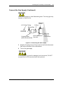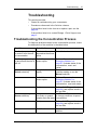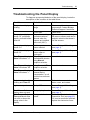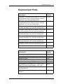
1
TurboVap II User’s Manual Copyright 2010, Biotage AB. All rights reserved. P/N 128099 Rev. 00 Preface 2 Preface Copyright This manual is published by Biotage AB, 10430 Harris Oaks Blvd. Suite C, Charlotte, NC 28269 U.S.A. Copyright 2010, Biotage AB. All rights reserved. Reproduction by any means or in any form of this manual or the products it describes is prohibited. Trademarks Biotage and TurboVap are trademarks of Biotage. Microsoft and Windows are either registered trademarks or trademarks of Microsoft Corporation in the United States and/or other countries. All other trademarks and registered trademarks are the property of their respective holders. Content The information in this manual may contain typographical errors or technical inaccuracies and is subject to change without notice. Modifications may also be made to the product described in this manual at any time. Proper Equipment Operation The TurboVap II Concentrator uses a patented gas vortex shearing technique to concentrate samples quickly. It is a microprocessor-controlled instrument for simultaneous, automated concentration of multiple samples with unattended operation, convenience, and speed. It is the customer's responsibility to design suitable methods for evaporation of their own samples. WARNINGS • • • The TurboVap II is NOT designed for in vitro testing or for use with highly corrosive samples. To reduce the risk of electric shock, do not remove the cover. No user serviceable parts are inside. Refer to qualified service personnel if help is required. Use this product only in the manner described in this manual. If the equipment is used in a manner not specified by the manufacturer, the protection provided by the equipment may be impaired. AVERTISSEMENTS • • P/N 128099 Rev. 00 Pour réduire le risque de choc électrique, ne pas retirer le couvercle. Ce produit ne contient aucune pièce pouvant être réparée par l’utilisateur. Au besoin, confier l’appareil à un réparateur qualifié. Ce produit ne doit être utilisé que comme décrit dans ce manuel. Si cet appareil est utilisé d’une manière autre que celle spécifiée par le fabricant, la protection fournie par l’appareil peut être entravée. TurboVap II User’s Manual Biotage AB Preface 3 Product Safety Warning The TurboVap II power switch is the same kind of power switch used on most laboratory equipment such as gas chromatographs, spectrophotometers, liquid chromatographs, and computers. The TurboVap products are safely used in the laboratory when “Good Laboratory Practices” are followed as with any other lab equipment. All fans are brushless motor fans and will not ignite vapors. The TurboVap is not classified as “Explosion Proof” and its use is at the discretion and risk of the operator or laboratory supervisor/manager. Your TurboVap product has been designed with safety as a foremost consideration. These products are equipped with a non-arcing fan, solid state electronics, and provisions for vapor collection. Do not change the configuration of the TurboVap II ventilation system. Please consult with Biotage if you have any questions or concerns. WARNING TurboVap products are NOT classified as “Explosion Proof.” The power switch is an arcing source and could ignite explosive vapors if present. Contact Biotage 1-Point Support Biotage 1-Point Support provides expert services including telephone troubleshooting of products, repair instructions, service dispatching and replacement part information. Before you call: Check the online Help and the manual for a probable cause and solution to your question. Have the following information available for the customer support representative: • Workstation serial number(s) • If applicable, the error displayed on the LCD display To reach the Biotage 1-Point Support: US: 1-800-446-4752 or [email protected] Europe and Rest of the World: +46 18 56 57 11 or [email protected] Japan: +81 422 28 1233 or [email protected] Biotage Product Repair Depot The Biotage Product Repair Depot offers product repair services, upgrades, refurbishment and installation at reasonable costs and with quick turnaround for all customer-owned equipment and accessories. For further information or to obtain a quotation for services, contact the Depot: US: 1-800-446-4752 or [email protected] Europe and Rest of the World: +46 18 56 57 11 or [email protected] Japan: +81 422 28 1233 or [email protected] Features of the Biotage Product Repair Depot: • Factory-trained repair technicians • Two week turnaround from receipt at Biotage P/N 128099 Rev. 00 TurboVap II User’s Manual Biotage AB Preface 4 Shipping: Customers are responsible for shipments both to and from Biotage, specifying the carrier and choice of service. Return Policy: To ensure a safe environment for all our technicians, it is mandatory for each returned product to include our chemical questionnaire stating contact chemicals, chemicals used during application and cleaning steps taken prior to shipment. Processing: Once the product is returned, it is evaluated for necessary repairs. The customer is contacted with an estimate and may choose to go ahead with the repair or decline service. If service is denied, a minimum evaluation charge may apply. Upon completion of the repair, a purchase order or appropriate means of payment is required before return shipment. Service and Customer Support Plans Biotage offers a full range of services to ensure your success. From our original factory warranty through a comprehensive line of customer support plans, Biotage AB offers you Field Service Engineers and In-house Specialists who are dedicated to supporting your hardware, software and application development needs. US: 1-800-446-4752 or [email protected] Europe and Rest of the World: +46 18 56 57 11 or [email protected] Japan: +81 422 28 1233 or [email protected] Our programs can include such useful services as: • preventative maintenance • diagnostic servicing performed on-site by Biotage AB field service engineers • extended use of the Biotage AB 1-Point Support Center • automated, remote troubleshooting • software updates • after-hour, weekend and holiday support • repair depot servicing • parts, labor and travel expense coverage • other customized services upon request FCC This device complies with part 15 of the FCC (United States Federal Communications Commission) Rules. Operation is subject to the following two conditions: • This device may not cause harmful interference, and • This device must accept any interference received, including interference that may cause undesired operation. CE This device complies with all CE rules and requirements. P/N 128099 Rev. 00 TurboVap II User’s Manual Biotage AB Preface 5 NOTE Changes or modifications to this equipment not expressly approved by the party responsible for compliance could void the user’s authority to operate the equipment. REMARQUE Tout changement ou modification apporté à cet instrument non expressément approuvé par l’entité responsable de la conformité peut annuler l’autorisation d’opérer l’appareil accordée à l’utilisateur. Table of Symbols Table 1 contains symbols that identify particularly important information and alert you to the presence of hazards. These symbols may appear in this manual and/or on the product it describes. Table 1. Important Symbols Symbol Symbole Description Description DANGER: An imminently hazardous situation, which, if not avoided, will result in death or serious injury. DANGER: Situation présentant un danger imminent qui, s’il n’est pas éliminé, peut entraîner des blessures graves, voire la mort. WARNING: Caution, risk of danger. Refer to the User’s documentation. AVERTISSEMENT: Attention, danger potentiel. Se reporter à la documentation de l’utilisateur. NOTE: A cautionary statement; an operating tip or maintenance suggestion; may result in instrument damage if not followed. REMARQUE: Énoncé indiquant une précaution à prendre, un conseil de fonctionnement ou une suggestion d’entretien; son non-respect peut provoquer des dommages à l’instrument. Hazardous voltage; risk of shock injury. Tension dangereuse; risque de blessure par électrocution. Crush hazard. Risk of body parts, hair, jewelry, or clothing getting caught in a moving part. Danger d’écrasement. Faire attention que les parties corporelles, les cheveux, les bijoux ou les vêtements ne soient pas pris dans une pièce mobile. Risk of puncture injury. Risque de blessure par piqûre. Risk of eye injury; wear safety glasses. Risque de lésion oculaire; porter des lunettes de sécurité. P/N 128099 Rev. 00 TurboVap II User’s Manual Biotage AB Preface 6 Table 1. Important Symbols (Continued) Symbol Symbole Description Description Risk of exposure to biohazards. Risque d’exposition à biohazards. Risk of fire. Risque d’incendie. Risk of poison. Risque d’empoisonnement. Risk of explosion. Risque d’explosion. Hazardous fumes. Émanations dangereuses. Hot surface; risk of burns. Surface chaude; risque de brûlures. Protective ground symbol. Symbole de terre de protection. Ground symbol. Symbole de terre. Fuse. Fusible. Alternating current. Courant alternatif. On (supply). Marche (alimentation). Off (supply). Arrêt (alimentation). CE compliance mark. Marque de conformité CE. Signifies that the unit has passed safety tests for grounding, power line transience, and current leakage. Signifie que l’appareil a réussi les tests de sécurité pour la mise à la terre, le courant transitoire de ligne d’alimentation et la perte de courant. Input. Entrée. Output. Sortie. P/N 128099 Rev. 00 TurboVap II User’s Manual Biotage AB Preface 7 Table 1. Important Symbols (Continued) Symbol Symbole Description Description Equipment labels are color coded: Les étiquettes de l’appareil sont codées couleur: Yellow Red Blue Green Jaune Rouge Bleu Vert P/N 128099 Rev. 00 Caution, risk of danger Stop Mandatory action Safe condition or information Attention, danger potentiel Arrêter Intervention obligatoire Condition sûre ou informations de sécurité Helpful hints, additional information Conseils utiles, informations supplémentaires TurboVap II User’s Manual Biotage AB Table of Contents 8 Table of Contents Preface .................................................................................................................... 2 Introduction .......................................................................................................... 11 Gas Vortex Shearing Action .............................................................................. 11 Automated Evaporation ..................................................................................... 12 Sensors............................................................................................................. 12 Adjustable ......................................................................................................... 12 Convenience ..................................................................................................... 13 Mild Conditions.................................................................................................. 13 Multiple Sample Processing .............................................................................. 13 Requires No Hood ............................................................................................. 13 Independent Operation ...................................................................................... 13 Vapor Removal ................................................................................................. 13 TurboVap II Hardware ........................................................................................... 14 TurboVap II - Front ............................................................................................ 14 TurboVap II - Rear ............................................................................................ 16 Front Panel Controls ......................................................................................... 18 Endpoint Selections and Functions .............................................................. 18 Cell Selections and Functions ...................................................................... 20 Installing the TurboVap II Concentrator .............................................................. 21 Unpacking the TurboVap II ................................................................................ 21 Parts Supplied................................................................................................... 21 Other Required Items ........................................................................................ 21 Site Preparation Requirements.......................................................................... 22 Installing the TurboVap II .................................................................................. 24 Select the Location for the TurboVap II ........................................................ 24 Clean the Glassware ................................................................................... 24 Remove the Sensors for Operation Above 60°C (if necessary) .................... 24 Confirm That Your Racks and Sample Tubes Match .................................... 24 Connect the Gas Supply .............................................................................. 24 Fill the Water Bath ....................................................................................... 26 Connect the Power Cord .............................................................................. 27 Turn On the Power ...................................................................................... 27 Power-Up Diagnostics ................................................................................. 27 Determine Optimal Concentration Conditions .................................................... 28 Determine Appropriate Water Bath Temperature ............................................... 28 Precautions When Setting Water Bath Temperature .................................... 28 Setting the Water Bath Temperature............................................................ 29 Determine Appropriate Gas Pressure & Time Settings ...................................... 30 Setting the Gas Pressure ............................................................................. 30 Determine the Appropriate Endpoint and Time Settings .................................... 31 Endpoint Selection Notes............................................................................. 31 When to Use Each Method .......................................................................... 32 P/N 128099 Rev. 00 TurboVap II User’s Manual Biotage AB Table of Contents 9 Time - Concentrating for a Specified Time ................................................... 32 Sensor - Concentrating Until the Sensor Detects the Endpoint .................... 33 Sensor and Time - Concentrating for a Set Time Past Endpoint Detection ... 34 Manual - Concentrating Until the Start/Stop Button is Pressed..................... 35 Optimizing Recoveries with 1mL Sample Stem Tubes ....................................... 36 Final Concentration Conditions Established for Your Sample ............................ 37 Operation .............................................................................................................. 38 Preparing the Unit ............................................................................................. 38 Starting the Concentration................................................................................. 39 Stopping the Concentration ............................................................................... 40 Notes About Stopping .................................................................................. 40 When the Endpoint is Reached .................................................................... 40 To Silence the Alarm ................................................................................... 40 Cell Light Behavior ...................................................................................... 40 Time Display Behavior ................................................................................. 41 Manual Operation ........................................................................................ 41 Removing the Sample Tube from the Unit ......................................................... 42 Removing the Sample from the Tube ................................................................ 42 Shutting Down ................................................................................................... 43 Maintenance .......................................................................................................... 44 Daily Maintenance............................................................................................. 44 Routine Maintenance ....................................................................................... 45 Sensor Maintenance ......................................................................................... 46 Water Bath Maintenance ................................................................................... 46 Glassware Maintenance .................................................................................... 46 Replacing the Fuses.......................................................................................... 47 Cleaning the Water Bath ................................................................................... 48 Refilling the Water Bath..................................................................................... 49 Removing and Replacing the Sensors ............................................................... 50 Remove the Covers and Unplug the Connectors.......................................... 50 Remove the Sensors ................................................................................... 51 Replace the Rack and Covers to Operate Without Sensors ......................... 51 Operating Requirements When Sensors Are Removed ................................ 52 Installing the Sensors .................................................................................. 52 Changing the Rack ............................................................................................ 53 Before Changing the Rack ........................................................................... 53 Changing a Rack from 0.5 mL to 1.0 mL (Installing Spacer)......................... 54 Changing a Rack from 1.0 mL to 0.5 mL (Removing Spacers) ..................... 55 Long Term Storage ........................................................................................... 56 Troubleshooting ................................................................................................... 57 Troubleshooting the Concentration Process ...................................................... 57 Troubleshooting the Panel Display .................................................................... 59 Troubleshooting the Unit ................................................................................... 60 Procedure for Dislodging Bubbles ..................................................................... 61 Software Diagnostics......................................................................................... 62 Power Up Diagnostics.................................................................................. 62 P/N 128099 Rev. 00 TurboVap II User’s Manual Biotage AB Table of Contents 10 Cell Diagnostics ........................................................................................... 64 Faulty Valve................................................................................................. 66 Expected Sensor Optical Output Values ...................................................... 66 Incorrect Sensor Values............................................................................... 66 Specifications ....................................................................................................... 67 Environmental ................................................................................................... 67 Power................................................................................................................ 67 Dimensions ....................................................................................................... 67 Replacement Parts................................................................................................ 68 Index ...................................................................................................................... 71 P/N 128099 Rev. 00 TurboVap II User’s Manual Biotage AB Introduction 11 Introduction The TurboVap II Concentration Workstation is a microprocessorcontrolled concentrator that provides automated sample evaporation, unattended operation, convenience, and speed. The concentrator uses a patented gas vortex shearing action to maintain high evaporation rates under mild thermal conditions regardless of sample height in the tubes. This section of the manual describes the features of the TurboVap II evaporator. Figure 1. TurboVap II Gas Vortex Shearing Action The evaporator uses a patented “gas vortex shearing action” that maintains high evaporation rates regardless of sample height in the tubes. A helical flow of air (see Figure 2) is created by the stream of gas directed into each sample tube. The helical flow sets up a vortexing action that provides for sample homogeneity and continuous rinsing of the tube wall. The vapor-laden gas exits via an unobstructed path up the center portion of the tubes and is removed by an exhaust fan to the exhaust port in the back of the unit. Sample Tube Gas Vortex Shearing Action Gas Nozzle Water Bath Optical Sensor Stem Figure 2. Gas Vortex Shearing Action P/N 128099 Rev. 00 TurboVap II User’s Manual Biotage AB Introduction 12 Automated Evaporation The TurboVap II uses an integrated microprocessor to automatically time the concentration, control the water bath temperature, automatically turn off the gas, and perform operational diagnostics. Sensors Optical sensors in the water bath enable the TurboVap II to automatically stop the concentration when the sample level in the tube passes below the optical sensor. The final volume of the concentration, either 0.5 mL or 0.75 mL, depends on the size of the sample tube being used. The optical sensor tracks any slow changes in the optical density of the sample to assure that darkening or brightening samples do not stop the concentration prematurely. Once the sample passes below the optical sensor and remains below the sensor for a few seconds, the TurboVap II stops the concentration or starts the timer to concentrate for additional time. The stem size of the concentrator tubes determines the final volume when using the sensor endpoint. Tubes with a 0.5 mL stem concentrate to 0.5 mL; tubes with a 1.0 mL stem concentrate to 0.75 mL and have a calibrated mark on the tube for you to reconstitute to 1.0 mL. Adjustable The TurboVap II enables you to: • concentrate for a set time, • use the sensor endpoint to detect a level of 0.5 mL or 0.75 mL, • continue concentrating for a set time after reaching the sensor endpoint, • concentrate until stopped manually, • optimize the concentration rate by adjusting the gas pressure and water bath temperature. NOTE • P/N 128099 Rev. 00 Time, temperature, and gas pressure can be changed at any time. TurboVap II User’s Manual Biotage AB Introduction 13 Convenience The TurboVap II enables you to start a run of samples and leave the instrument unattended. When the concentration has finished, the gas turns off automatically and the concentrator sounds an alarm every 30 seconds until the samples are removed or Start/Stop is pressed. Mild Conditions The water bath provides sufficient warming without harming sample recovery. Multiple Sample Processing The concentrator nozzle block has six nozzles that extend into the tubes to supply gas for concentration. This allows up to six samples to be processed simultaneously. Requires No Hood The flip-down cover and exhaust system permit the unit to be placed on the bench rather than taking up valuable hood space. Independent Operation Concentration for each cell can be independently started or stopped at any time. Vapor Removal The solvent vapors are removed by an exhaust fan to the exhaust port in the back of the unit. From the exhaust port, the venting hose must be routed to a suitable outside ventilation system. P/N 128099 Rev. 00 TurboVap II User’s Manual Biotage AB TurboVap II Hardware 14 TurboVap II Hardware TurboVap II - Front Nozzle Block Concentrator Tube Front Panel Water Bath and Rack Gas Regulator Knob Power Switch Figure 3. TurboVap II Hardware, Front View Front Panel Controls the setup and operation of the concentrator. See “Front Panel Controls” on page 18 for details. Nozzle Block Directs the stream of gas into the sample tubes to create the gas vortex shearing action. Concentrator Tube (or sample tube) Holds the sample for concentration. Two types of tubes are available for detecting endpoints of 0.5 mL or 0.75 mL. Water Bath Warms the sample during concentration. The water bath operates over a temperature range of ambient to 90°C. The TurboVap II evaporator is not designed to cool, but the water bath temperature can be brought down as much as 15°C by using the evaporation as a cooling source. Cooling ability varies with the evaporation rate. WARNING Fire and burn hazard. DO NOT operate the TurboVap II without water in the water bath. P/N 128099 Rev. 00 TurboVap II User’s Manual Biotage AB TurboVap II Hardware 15 Rack Holds sample tubes during concentration. Cover Operation automatically pauses when the water bath cover is opened and resumes when the cover is closed. After an evaporation, open the cover to prevent condensation within the unit. Gas Regulator Knob Set the external gas supply to the instrument to be between 30 psi and 80 psi. Use the regulator knob to adjust the internal pressure (0 to 20 psi) for a desired helical gas flow directed at each of the sample tubes. The pressure gauge on the front panel displays the internal gas pressure. The gas is routed through a stainless steel manifold to each sample tube. WARNING • • To avoid injury to yourself, damage to the instrument, or loss or samples, DO NOT exceed 20 psi maximum gas pressure in the TurboVap II. Never use hydrogen or other flammable gases. The wrong gas may explode or catch on fire. Power Switch Turns the power on or off. WARNING The power switch is an arcing source and could ignite excessive explosive vapors if present. DO NOT change the position of the unit’s on/off power switch when explosive vapors are present. P/N 128099 Rev. 00 TurboVap II User’s Manual Biotage AB TurboVap II Hardware 16 TurboVap II - Rear Alarm Volume Control Service Panel Quick-Disconnect Gas Inlet Exhaust Port Power Entry Port Figure 4. TurboVap II Hardware, Rear View Alarm Volume Control The Alarm Volume control knob is located on the back of the TurboVap II. Turn the knob in either direction to change the volume of the alarm. • A repeating beep indicates a completed run. • A long beep indicates interrupted operation. • A short beep indicates a recognized key input. Quick-Disconnect Gas Inlet Connects the gas supply to the unit. The fitting has an internal shutoff that allows you to disconnect the concentrator from the gas supply without turning off the gas supply. WARNING • • To avoid injury to yourself or damage to the instrument, DO NOT exceed 80 psi maximum inlet pressure. Never use hydrogen or other flammable gases. The wrong gas may explode or catch on fire. Service Panel Provides service access to the sensor connectors. P/N 128099 Rev. 00 TurboVap II User’s Manual Biotage AB TurboVap II Hardware 17 Exhaust Port Solvent vapors are removed by an exhaust fan and routed to the exhaust port on the back of the unit. You must route the venting hose from the exhaust port to a proper ventilation system venting to the outside. The TurboVap II's design ensures that vapors are properly contained and are removed automatically from the laboratory environment when the system is operating properly. WARNING • • Exhaust gases may be hazardous and can contaminate the surrounding air. Consult the Material Safety Data Sheets (MSDS) for all of the solvents used. Use the exhaust hose provided to vent the gas to a hood or other ventilation device. Do not operate if the exhaust system is not working properly. Power Entry Port Supplies power to the unit and houses the fuses. WARNING • • P/N 128099 Rev. 00 To avoid the risk of fire or electrical shock, plug the power cord securely into a properly grounded outlet. Replace fuses ONLY with the same type and rating. TurboVap II User’s Manual Biotage AB TurboVap II Hardware 18 Front Panel Controls The control panel allows you to control concentration in the six tube positions. (Samples are not required in each position.) The microprocessor constantly monitors the control panel settings, enabling you to change the settings at any time during evaporation. Lights indicate when each cell is evaporating or has reached the selected endpoint. The Cell buttons enable you to stop the evaporation manually if desired. The two displays on the front panel can display the pressure, bath temperature, or time remaining. Figure 5. TurboVap II Control Panel Endpoint Selections and Functions Endpoint Select Button Selects the mode used to determine the endpoint of concentration. • Time (minutes) - to concentrate for the period of time in minutes specified by the Endpoint Time setting on the panel • Sensor- to concentrate until sensor detects a level of 0.5 or 0.75 mL (depending upon the style concentrator tube) • Sensor and Time - to concentrate past the 0.5 or 0.75 mL setting by the amount of time in minutes specified by the Endpoint Time setting on the panel • Manual - to concentrate until the operator presses the Start/Stop button for each cell P/N 128099 Rev. 00 TurboVap II User’s Manual Biotage AB TurboVap II Hardware 19 Bath Temperature Pushwheel Sets the desired water bath temperature. Endpoint Time Pushwheel Sets the desired time in minutes (total concentration time or additional time after sensor endpoint detection). Select Displayed Condition Button Selects the condition to be represented in the four digits displayed by the Condition and Value displays. • All - cycles the current conditions for pressure, water bath temperature, and time elapsed in the display fields. • Pressure - displays the current gas pressure in psi and bars. • Temperature - displays the current water bath temperature in C. • Time Elapsed - displays the time elapsed for each concentration process in minutes. • Diagnostics - displays the cell diagnostics. Condition and Value Display Examples When... Then... Pressure is selected the digits alternate between “xxPi” (psi) and “x.xbr” (bars), where xx is replaced with the actual value. Example: At 10 psi, the display alternates between the two displays shown below: Temperature is selected the digits show “xxC” where x is replaced with the actual value in C. Example: At 38C, the display shows: Note: The display blinks if the water bath temperature is more than 2 higher or lower than the set temperature. P/N 128099 Rev. 00 TurboVap II User’s Manual Biotage AB TurboVap II Hardware 20 When... Then... Time Elapsed is selected the digits show “#=xx” in sequence for all cells where # is replaced by the cell number and x is replaced with the actual value in minutes. Example: For a sample in cell position 5 where 12 minutes of concentration has elapsed, the display shows: Note: • “SE” appears in the Value display during the sensor portion of a Sensor & Time concentration. • “” appears in the Value display whenever the time exceeds 99 minutes during a Sensor or Manual concentration. • “--” appears in the Value display if the cell has been stopped or was not started. All is selected The digital display cycles through the pressure, temperature, and time elapsed readings. Diagnostics is selected The digits display the selected diagnostics (see “Software Diagnostics” on page 62). Cell Selections and Functions P/N 128099 Rev. 00 Selections Functions Start/Stop buttons Used to start or stop concentration. Note: Upon power up, the Start/Stop buttons will not work until an endpoint is selected. Cell Light When OFF, that cell position is not performing concentration. When ON, that cell position is currently performing a concentration. When BLINKING, that cell position has reached its endpoint. TurboVap II User’s Manual Biotage AB Installing the TurboVap II Concentrator 21 Installing the TurboVap II Concentrator Unpacking the TurboVap II Unpack the shipping container and verify that all items listed below are included. If any parts are damaged or missing, contact Biotage (see page 3). Parts Supplied The Biotage TurboVap II Concentration Workstation comes with the following parts: • Concentrator Unit • Water Bath Rack • Rack Adapter Kit for 1.0 mL stem glassware (already installed in 1.0 mL units) • Power Cord(s) - 220V models include two power cords, one for EU and one for UK • Venting Hose • 1/4” ID Gas tubing • Bag of two 1/4” Barb Fittings (1/8” NPT and 1/4” NPT) • Coupling Insert • Clear Bath Kit • Water Bath Siphon Pump • Plastic Water Bath Closures (six) • Startup Glassware (six pieces) - for ASE TurboVap II, see Other Required Items below. • Auxiliary Rack • User’s Manual CD • Reference Card Other Required Items • Startup Glassware for ASE TurboVap II must be purchased from Dionex at 1-800-346-6390 • Inert Gas Supply (nitrogen) • Distilled Water • Timer P/N 128099 Rev. 00 TurboVap II User’s Manual Biotage AB Installing the TurboVap II Concentrator 22 Site Preparation Requirements You must have an appropriate location with available gas and electrical sources and adequate ventilation as specified by these site preparation requirements before installing the TurboVap II concentrator. Space: Minimum bench space for the concentrator and any accessories: • Height: 12 inches (30.5 cm) • Width: 21.2 inches (53.8 cm) • Depth: 12 inches (30.5 cm) • Open Cover: 20 inches Work Area: Flat, level, stable surface Compressed Gas Supply: Clean, dry, regulated, nitrogen or other suitable gas, regulated to 30 psi minimum, 80 psi maximum. Biotage suggests using the supplied tubes and fittings. Devices added to the inlet supply line (such as moisture traps or filters) must not drop the pressure below 30 psi (2.1 bars) measured at the TurboVap II inlet fitting. NOTES • • Use of compressed air could contribute to the oxidation of some phenolic compounds and reduce sample recoveries. A ¼” line is recommended. Larger tubing might be necessary to maintain pressure if devices such as moisture traps and filters are added to the line. WARNING • • P/N 128099 Rev. 00 To avoid injury to yourself or damage to the instrument, DO NOT exceed 80 psi maximum supply pressure. Never use hydrogen or other flammable gases. The wrong gas may explode or catch on fire. TurboVap II User’s Manual Biotage AB Installing the TurboVap II Concentrator 23 Exhaust Duct: Requires a 2 inch diameter venting hose (exhaust duct tubing is supplied). The exhaust duct MUST go to a suitable ventilation system vented outside the laboratory. WARNING Exhaust gases may be hazardous. Consult the Material Safety Data Sheets (MSDS) for all of the solvents used. Power: 100/120VAC model 220/240 VAC model 100/120VAC +/- 10% 220/240 VAC +/- 10% 50 - 60 Hz 50 - 60 Hz Fuses: 100/120VAC model 220/240 VAC model (1) 10A, T250V (P/N 39164) (2) 5A, T250V (P/N 44412) Bath Capacity: • 6.4L maximum distilled water. DO NOT overfill. Gas Supply Fitting: To fit 1/4” ID gas tubing, for connection of gas supply Clear Bath Additive: 2 oz. kit supplied with unit WARNING Exposure to liquids may cause bacterial or viral hazards. Liquids can also be corrosive, flammable and/or toxic. Use good laboratory operating procedures when dealing with liquids. Refer to the MSDS (Material Safety Data Sheet) for detailed information. • • • • P/N 128099 Rev. 00 Avoid direct contact with liquids. Wear protective gloves and safety glasses. Dispose of liquids and containers properly. Do not overfill containers. TurboVap II User’s Manual Biotage AB Installing the TurboVap II Concentrator 24 Installing the TurboVap II Select the Location for the TurboVap II Select a flat, stable, dry bench space within 12 feet of adequate ventilation, and available sources of electricity and gas. NOTE While a laboratory hood is an ideal location for installation of the TurboVap, any location adequately vented through a proper ventilation system to the outside is acceptable. DO NOT vent the TurboVap through a trap. Clean the Glassware Glassware should be cleaned before use in the TurboVap II. Clean and rinse the glassware according to your laboratory protocol. Residue remaining on either the inside or outside of the stem can impact sensor operation. Remove the Sensors for Operation Above 60C (if necessary) If you will be operating the TurboVap II at temperatures above 60C, you must remove the sensors. See “Removing and Replacing the Sensors” on page 50 for detailed instructions on removing the sensors. Confirm That Your Racks and Sample Tubes Match Confirm that the sample tubes you are using are compatible with the racks. Connect the Gas Supply Determine if an inline carbon trap is necessary and then connect your gas supply using the ¼ inch tubing supplied. To connect the gas supply: 1 Turn off the gas supply. 2 Connect one end of the 1/4” ID gas tubing to the gas supply and connect the other end to the barbed fitting on the Coupling Insert (see Figure 6 on page 25). P/N 128099 Rev. 00 TurboVap II User’s Manual Biotage AB Installing the TurboVap II Concentrator 25 Connect the Gas Supply (Continued) WARNING Never use hydrogen or other flammable gases. The wrong gas may explode or catch on fire. 1/4” ID Gas Tubing O-Ring Release Button Barbed End Quick-disconnect Coupling Insert (with internal shutoff) Gas Inlet Side View of back of Concentrator Figure 6. Connecting the Gas Supply 3 Snap the Coupling Insert (O-ring end) into the Quick-disconnect Gas Inlet on the back of the concentrator. 4 Turn on the gas supply. WARNING To avoid injury to yourself or damage to the instrument, DO NOT exceed 80 psi (5.52 bars) maximum inlet pressure. P/N 128099 Rev. 00 TurboVap II User’s Manual Biotage AB Installing the TurboVap II Concentrator 26 Install the Exhaust Tubing If the concentrator is not placed in a hood: 1 Slide one end of the venting hose over the exhaust port. 2 Route the hose to a suitable external air ventilation system or hood. Ensure that the ventilation system is operating whenever the TurboVap II is in use. WARNING • Health hazard. Gas fumes exiting this instrument can contaminate the air you breathe. Maintain proper ventilation. Use only venting hoses with appropriate length and internal diameter (I.D.) to avoid excessive pressure drop. • The following hoses can be used to vent the TurboVap II: Maximum Hose Length Internal Diameter 12.5 ft (3.8m) 2 inch (5cm) I.D. 30 ft (9.1m) 2.5 inch (6.4cm) I.D. 60 ft (18.2m) 3 inch (7.6cm) I.D. Fill the Water Bath When you are filling the water bath, make sure that: • placing the sample tubes in the water bath does not cause an overflow. • the water level in the bath is as high as the initial solvent level in the sample tube. To fill the water bath: 1 Place a concentrator tube in five positions. 2 Pour about 1 Liter of distilled water into the bath through the empty position. 3 Add 15 drops of Clear Bath. 4 Add distilled water until the water’s surface is as high as the initial solvent level in the sample tube. WARNING To avoid the risk of fire or burn injuries, do NOT operate the TurboVap II without water in the bath. P/N 128099 Rev. 00 TurboVap II User’s Manual Biotage AB Installing the TurboVap II Concentrator 27 Connect the Power Cord 1 Plug the power cord securely into the receptacle on the back of the unit. Make sure the plug is fully inserted. 2 Connect the 3-pronged end to an appropriate power source. WARNING To avoid the risk of fire or electrical shock, plug the power cord into a properly grounded outlet. Turn On the Power To turn on the concentrator, turn ON the switch located on the lower left side of the TurboVap. When the power is turned on, the PowerUp diagnostics described below will run automatically. Note: Upon power up, the Start/Stop button for the six cells will not work until an endpoint has been selected. Power-Up Diagnostics When the power is turned ON, the following diagnostics occur: Display Test - During the first four seconds after power up, all display lights are lit. Confirm that all lights are working properly. Also during this time, raising and lowering the cover sounds the beeper to confirm the cover switch is functioning. Normal operation begins after four seconds. P/N 128099 Rev. 00 TurboVap II User’s Manual Biotage AB Determine Optimal Concentration Conditions 28 Determine Optimal Concentration Conditions You should determine the settings that will best concentrate your samples before operation. You should determine the desired: • water bath temperature • gas pressure • endpoint selection To prepare the TurboVap II: 1 Turn the evaporator's power ON. NOTE: The unit should always be ON whenever it contains samples so that the fan can remove exhaust. 2 Turn the gas supply ON. 3 Set the pressure on the gas supply regulator to 0 (zero) psi. 4 Remove all tubes from the evaporator. Determine Appropriate Water Bath Temperature Since the concentrator’s high evaporation rates eliminate the need for a high temperature water bath, the bath operates over a mild temperature range of ambient to 95C. This eliminates hot spots and improves sample recovery for more volatile compounds. The water bath also can be brought down below room temperature by using evaporative cooling. Cooling ability varies with the concentration rate. Precautions When Setting Water Bath Temperature Remove the sensors if you intend to set the water bath temperature at or above 60C. See “Removing and Replacing the Sensors” on page 50 for detailed instructions on removing the sensors. WARNING • • P/N 128099 Rev. 00 Do not operate at a temperature greater than 60C unless the sensors have been removed from the bath. Do not operate the unit without water in the water bath. TurboVap II User’s Manual Biotage AB Determine Optimal Concentration Conditions 29 NOTES • • Open the cover and leave the power on after concentration until the fan chamber is dry. If operating with a high water bath temperature (for example, concentrating water samples), condensation may form on the inside cover, drip through the vents into the fan chamber, and cause corrosion if the cover is left closed. When the concentrator is not in use, place plastic closures over the bath positions and keep the lid open. If power is left on, the bath heater automatically turns off after the lid has been opened for one hour. When selecting the water bath temperature, consider the following: • Faster evaporation occurs as the water bath temperature is increased. However, highly volatile analytes can be lost if allowed to sit for extended periods of time in a warm bath. • You can select a water bath temperature just below the boiling point of the solvent in the sample tube. Boiling the solvent affects sensor operation and can risk loss of sample. • You can use a water bath temperature above the boiling point of your solvent if the gas pressure is high enough to create a cooling effect over the solvent. Using a higher water bath temperature speeds the concentration and can increase recoveries. For example: the bath temperature may be 42C but the solvent temperature could be less than 42C if the gas flowing over the solvent causes cooling. • A temperature setting of “00” turns off the heaters. Setting the Water Bath Temperature 1 Set the water bath temperature using the numeric pushwheel. 2 Place plastic closures over any empty water bath positions. 3 Press the Select Displayed Condition button until Temperature is selected. 4 Allow the bath to come to temperature (display stops blinking) before using the concentrator. NOTE As the bath warms up, bubbles may form around the sensor. If given enough time (approximately 1/2 hour), bubbles should dissipate. In most cases, sample tube insertion will free bubbles. P/N 128099 Rev. 00 TurboVap II User’s Manual Biotage AB Determine Optimal Concentration Conditions 30 Determine Appropriate Gas Pressure & Time Settings When selecting the gas pressure, keep in mind that: • higher gas pressure causes faster evaporation rates • excessively high operating pressure can cause loss of analyte due to splashing • for the best results, always use the highest gas pressure possible without causing splashing • as the sample volume decreases during a concentration, increase the operating pressure. This will reduce the overall concentration time. • To avoid damage, supply inlet pressure to the instrument must not exceed 80 psi (5.52 bars). • For proper operation, pressure to the instrument must be at least 30 psi (2.07 bars) and operating pressure within the TurboVap II usually should be between 8 and 15 psi (0.6 and 1.0 bars). WARNING • • To avoid injury to yourself or damage to the instrument, do NOT exceed 80 psi maximum supply pressure. To avoid injury to yourself or damage to the instrument, do NOT exceed 20 psi maximum pressure in the TurboVap II. Setting the Gas Pressure 1 Pull the regulator knob out and turn it fully counterclockwise to start at a pressure of zero. 2 Press the Select Displayed Condition button until Pressure is selected. The Condition and Value displays alternate between a pressure reading in psi and in bars. 3 Press the Endpoint Select button until Manual is selected. 4 Place a concentrator tube with a typical starting volume of sample or solvent into one of the concentrator positions. P/N 128099 Rev. 00 TurboVap II User’s Manual Biotage AB Determine Optimal Concentration Conditions 31 Setting the Gas Pressure (Continued) 5 Press the Start/Stop button for the cell position. 6 Slowly turn the regulator knob clockwise to increase the gas supply pressure until a swirling action without splashing is observed. The reading is normally between 8 and 15 psi (0.6 and 1.0 bars). Push the knob in to lock in place. 7 If you will be using any of the endpoint selections that require a time setting, use a stopwatch or clock to time how long it takes to evaporate the sample to the desired endpoint. The Time Elapsed display can be used, but it will not show times more than 99 minutes. 8 When you are ready to stop concentration, press the Start/Stop button for the cell position. Note: It is normal for the pressure reading to rise slightly when concentration is complete (gas is not flowing). 9 Make necessary adjustments to water bath temperature and gas pressure to achieve the best settings, then record this information along with the final Endpoint Time (if required). Determine the Appropriate Endpoint and Time Settings There are four ways to complete concentration. • concentrating for a set time (in minutes) • concentrating until the sensor detects a liquid level • concentrating for a set time after the sensor detects a liquid level • concentrating until the operator presses Start/Stop (manual mode) A description of each method follows. Endpoint Selection Notes • All selection lights flash after power up until a selection is made. • The endpoint selection applies to all cells. • Endpoint Select cannot be changed during concentration. P/N 128099 Rev. 00 TurboVap II User’s Manual Biotage AB Determine Optimal Concentration Conditions 32 When to Use Each Method The following table gives some example of when you would choose a particular endpoint selection. Use... When... Time (minutes) • the sensors are removed because the water bath temp. is >60C. • sample coats the glass or darkens too rapidly. • sample evaporates too slowly. • a volume greater than 0.5 or 0.75 mL is desired as the endpoint. Sensor You want full automation of sample concentration to a fixed endpoint volume (acceptable for most samples at a water bath temperature under 60C). Sensor and Time You want to concentrate past the endpoint of the glassware (0.5 mL or 0.75 mL) or to dryness (acceptable for some samples at a water bath temperature under 60C). Manual • water bath temp. is >60C so the sensors are removed • sample coats the glass or darkens too rapidly • you need to concentrate for a time greater than 99 minutes Time - Concentrating for a Specified Time To concentrate for a set time, select the Time endpoint. Perform the following steps to set the front panel. 1 Press the Endpoint Select button until Time is selected. 2 Use the Endpoint Time wheels to set the desired time, in minutes, for concentration. 3 Press the Start/Stop button for the desired cell position(s). P/N 128099 Rev. 00 TurboVap II User’s Manual Biotage AB Determine Optimal Concentration Conditions 33 Reading the Time Elapsed Display During a Timed Concentration To view the actual time elapsed for each sequential cell position during a timed concentration, select either Time Elapsed or All. The Condition display shows the cell position, and the Value display shows the time elapsed. Example: Figure 7. Time Elapsed - Time Endpoint When the concentration is finished, Time Elapsed continues to show the time until the cover is raised and closed, or the Start/Stop button is pressed, at which time the Time Elapsed display shows “-”. Sensor - Concentrating Until the Sensor Detects the Endpoint To use the optical sensors to concentrate to a volume of either 0.5 mL or 0.75 mL, select the Sensor endpoint. The volume at which concentration stops depends on the stem length of the concentrator tube. Perform the following steps to set the front panel. 1 Press the Endpoint Select button until Sensor is selected. 2 Press the Start/Stop button for the cell position(s). Reading the Time Elapsed Display During a Sensor Detect Concentration To view the time elapsed during a concentration using the Sensor endpoint, select either Time Elapsed or All. The Condition display shows the cell position, and the Value display shows the time elapsed. Example: Figure 8. Time Elapsed - Sensor Endpoint P/N 128099 Rev. 00 TurboVap II User’s Manual Biotage AB Determine Optimal Concentration Conditions 34 Sensor Endpoint Considerations Two conditions affect optical sensing: Water Bath- If the water bath temperature is set above 60C, the sensors must be removed. See “Removing and Replacing the Sensors” on page 50 for detailed instructions on removing the sensors. Sample Clarity - clear, slowly darkening or opaque (at 940 nm) samples reliably concentrate using the Sensor endpoint selection. Samples which darken too rapidly as concentration proceeds may actuate the sensor prematurely. If this happens, press the Start/Stop button for the sensor to start with a new baseline reading and continue concentration. If starting a new baseline is unacceptable, determine concentration time and use the Time (minutes) option, or operate manually by using the Manual selection. Sensor and Time - Concentrating for a Set Time Past Endpoint Detection To continue concentration after the sensor detects a 0.5 or 0.75 mL endpoint (depending on glassware), select the Sensor and Time endpoint. Perform the following steps to set the front panel. 1 Press the Endpoint Select button until Sensor and Time is selected. 2 Use the Endpoint Time wheels to set the desired time, in minutes, for concentration to continue AFTER endpoint detection. 3 Press the Start/Stop button for the cell position(s). Reading the Time Elapsed Display when Concentrating for a Set Time Past Endpoint Detection While performing a concentration using the Sensor and Time endpoint, the Value display shows the letters “SE” until the endpoint is reached. Once the endpoint is reached, the elapsed time after the endpoint is displayed in the Value field as shown in Figure 9. Figure 9. Time Elapsed - Sensor and Time Endpoint P/N 128099 Rev. 00 TurboVap II User’s Manual Biotage AB Determine Optimal Concentration Conditions 35 Sensor and Time Endpoint Considerations The same considerations exist for this selection as for the SENSOR selection. See “Sensor Endpoint Considerations” on page 34. Manual - Concentrating Until the Start/Stop Button is Pressed To operate manually, select the Manual endpoint. Perform the following steps to set the front panel. 1 Press the Endpoint Select button until Manual is selected. 2 Press the Start/Stop button for the cell position(s). Reading the Time Elapsed Display During a Manual Concentration To display the actual time elapsed for each sequential cell position while performing a manual concentration, select either Time Elapsed or All. The Condition display shows the cell position, and the Value display shows the time elapsed as shown in Figure 10. Figure 10. Time Elapsed - Manual If the elapsed time exceeds 99 minutes, the Value display is replaced with “”. as shown in Figure 11. Figure 11. Time Elapsed - Manual, more than 99 minutes P/N 128099 Rev. 00 TurboVap II User’s Manual Biotage AB Determine Optimal Concentration Conditions 36 Optimizing Recoveries with 1mL Sample Stem Tubes To achieve the best recoveries: • Clean and bake the sample tubes according to the standard cleaning techniques for your method. • Adjust the concentration conditions as needed: • Operate at a gas pressure between 8 and 15 psi (0.6 and 1.0 bars). • If the concentrator tubes are initially FULL, start with a low gas pressure, and increase the pressure as the volume in the tube decreases. • Select a water bath temperature carefully. For methylene chloride acceptable temperatures can range from 40-45C. • Remove samples promptly, once the endpoint is achieved. • Use the proper technique for removing the samples from the concentrator tubes. 1mL tubes used with the 1mL concentration rack can eliminate the need for traditional triple quantitative transfer techniques. The final crude or cleaned up extract can be taken to 1mL directly in the TurboVap concentrator tube. 1 Choose Sensor for your Endpoint Selection; set gas pressure at 10 psi and the bath temperature at 39C. 2 Working on the bench or in a fume hood, add the sample to the TurboVap tubes. Do not add samples to the tubes while the tubes are in the TurboVap. 3 Start the concentration. 4 When the alarm sounds, remove the sample tube from the water bath. Failure to remove the tube promptly may result in analyte loss. 5 With a Pasteur pipette, add solvent to the 1mL line. P/N 128099 Rev. 00 TurboVap II User’s Manual Biotage AB Determine Optimal Concentration Conditions 37 Optimizing Recoveries with 1mL Sample Stem Tubes (Continued) 6 Take the entire 1 mL sample into the Pasteur pipette and rinse the lower 25% of the TurboVap tube (i.e. 2 inches above the cone shape on the cylinder wall) ten to fifteen times as shown in Figure 12. Rinse the lower 25% of the tube Bring to a volume of 1.0 mL Sample Figure 12. Rinsing the Concentrator Tube 7 Solvent evaporation during this rinsing will have reduced the volume. Add fresh solvent to bring the sample to 1 mL. Rinse the tube walls two more times and transfer the sample to an autosampler vial. Final Concentration Conditions Established for Your Sample After experimenting with the selections presented in this section, you should have established your settings for the following concentration conditions: Water Bath Temperature Endpoint Selection: • Time (minutes) • Sensor • Sensor and Time • Manual Gas Pressure Use this information when following the routine operation steps provided in the next section. P/N 128099 Rev. 00 TurboVap II User’s Manual Biotage AB Operation 38 Operation This section describes how to operate the TurboVap II Concentration Workstation using the following procedures: • preparing the unit (see below) • starting the concentration process (see page 39) • stopping (if running in manual mode or need to interrupt) (see page 40) • removing the sample tube (see page 42) • removing the concentrated sample (see page 42) • shutting down after operation (see page 43) Preparing the Unit Prepare the concentrator by performing the following steps. 1 Check that the incoming gas supply is turned on and has sufficient reserve for the sample run. 2 Confirm that the water bath rack accommodates your sample tube’s stem size. 3 Check the water level in the water bath. It should be about as high as the initial solvent level in the sample tube. 4 With the cover down, turn the unit on and set the Bath Temperature pushwheel. 5 Select the Temperature display and allow time for the water bath to come to temperature (temperature display stops blinking). Note: If using sensors, dislodge bubbles from around the optics. 6 Place clean concentrator tubes in the auxiliary rack and add sample. 7 Remove the plastic closures from the concentrator positions to be used. 8 Open the cover and place the concentrator tube (with sample) in the water bath. 9 Close the cover. P/N 128099 Rev. 00 TurboVap II User’s Manual Biotage AB Operation 39 Starting the Concentration Starting concentration involves the following steps: 1 Press Endpoint Select until the desired mode is selected. 2 If applicable, set the Endpoint Time pushwheel to the desired time. 3 Press Select Displayed Condition until Pressure is selected. Pull out the regulator knob, adjust the gas pressure as needed, and push in to lock the knob in place. 4 Press the cell position Start/Stop button. The corresponding cell light comes on. NOTE Time, temperature, and gas pressure may be changed at any time. Display During Operation While the concentrator runs, the Condition and Value displays reflect the status of whichever condition is selected - Pressure, Temperature, Time Elapsed, Diagnostics, or All. Gas Flow During Operation When you are concentrating using the Sensor or Sensor & Time selection, the gas flow may stop and start several times as the meniscus of the sample approaches the sensor optics. If the pressure drops below 3 psi (0.2 bars) during a concentration, the unit will beep rapidly, alerting you to check the incoming gas supply. P/N 128099 Rev. 00 TurboVap II User’s Manual Biotage AB Operation 40 Stopping the Concentration When... Then... running manually (last endpoint selection) Press Start/Stop button for the corresponding cell. you need to pause the concentration process Lift the cover. (Lowering the cover resumes operation). you need to stop the Press Start/Stop button for the concentration corresponding cell. process (This resets the time.) unconditionally Notes About Stopping • Starting & stopping is independent for each cell. • If concentration is stopped and restarted, the time is cleared and a new elapsed time begins - it does not continue from where it was stopped. • Opening the cover turns off the gas flow and suspends timing; lowering the cover resumes operation. Note: Timing is not cleared as when Start/Stop is pressed. • It is normal for the gas pressure to rise slightly when concentration finishes or is stopped (gas is not flowing). When the Endpoint is Reached When a cell reaches its selected endpoint, the light next to its Start/Stop button blinks and the beeper sounds briefly every thirty seconds. To Silence the Alarm To silence the beeper, raise the cover. Note: If there is a rapid beeping or continuous beep, refer to the diagnostics section and check inlet pressure. Cell Light Behavior The light for each cell that has reached its endpoint will continue to blink when the cover is raised, indicating which cells require attention. When the cover is lowered, all blinking lights turn off. P/N 128099 Rev. 00 TurboVap II User’s Manual Biotage AB Operation 41 Time Display Behavior When the concentration is finished, Time Elapsed continues to show the time until the cover is raised and closed, or the Start/Stop button is pressed, at which time the Time Elapsed display shows “-”. Manual Operation If operating the concentrator manually, the cell light blinks when you press the cell’s corresponding Start/Stop button. Pressing the Start/Stop button again turns the light off. P/N 128099 Rev. 00 TurboVap II User’s Manual Biotage AB Operation 42 Removing the Sample Tube from the Unit 1 Promptly remove the concentrator tube from the water bath and place it in the auxiliary rack. Note: Prompt removal of the completed tube is important since • highly volatile compounds can be lost if allowed to sit for an extended period of time. • steam from the water bath could condense on the cover and may drip into sample tubes if they are left in place. WARNING • • Avoid spilling solvents into the water bath. If solvents do spill into the water bath, follow MSDS safe handling instructions and immediately change the water in the water bath. Rinse the unit with distilled water.Refer to MSDS (Material Safety Data Sheets). To avoid injury to yourself or damage to the instrument, handle broken glass (broken tubes) with care. 2 If your initial sample volume exceeded the tube capacity, add remaining sample to the tube after it has been transferred to the auxiliary rack - not while the tube is still in the water bath - and repeat the concentration process. 3 Place plastic closures over empty bath positions. 4 Clean the concentrator tubes between samples according to your laboratory practice. 5 Add distilled water to the bath, if necessary. Removing the Sample from the Tube The gas vortex shearing action automatically rinses the vertical side walls as evaporation occurs, but for optimum recoveries, you should rinse the lower, angled portion of the concentrator tube to recover any sample left behind. See “Optimizing Recoveries with 1mL Sample Stem Tubes” on page 36. P/N 128099 Rev. 00 TurboVap II User’s Manual Biotage AB Operation 43 Shutting Down When the unit is no longer in use: 1 Replace the plastic closures in each cell position. 2 Leave the cover open to keep moisture from accumulating on the inside cover. NOTES • • After concentration, keep the cover open and the unit on until the fan chamber is dry. If operating with a high water bath temperature (for example, concentrating water samples), condensation may form on the inside cover, drip through the vents into the fan chamber, and may cause corrosion over time. When concentrator is not in use, place plastic closures over the bath positions and keep the lid open. If power is left on, the bath heater automatically shuts off after the lid has been opened for one hour. 3 Clean the concentrator tubes according to your laboratory practice. 4 Turn off the power and incoming gas supply. (optional) P/N 128099 Rev. 00 TurboVap II User’s Manual Biotage AB Maintenance 44 Maintenance This section contains the following maintenance procedures: • “Daily Maintenance” on page 44 • “Routine Maintenance ” on page 45 • “Sensor Maintenance” on page 46 • “Water Bath Maintenance” on page 46 • “Glassware Maintenance” on page 46 • “Replacing the Fuses” on page 47 • “Cleaning the Water Bath” on page 48 • “Refilling the Water Bath” on page 49 • “Removing and Replacing the Sensors” on page 50 • “Changing the Rack” on page 53 • “Long Term Storage” on page 56 Daily Maintenance • During Power Up diagnostics, confirm all displays are accurate. • Check to ensure water bath is full and clean. • Check that your tank has enough nitrogen for daily operation. WARNING Never use hydrogen or other flammable gases. The wrong gas may explode or catch on fire. • Avoid spilling any solvents on the control panel. • Avoid spilling any solvents in the water bath. WARNING Exposure to liquids may cause bacterial or viral hazards. Liquids can also be corrosive, flammable and/or toxic. Use good laboratory operating procedures when dealing with liquids. Refer to the MSDS (Material Safety Data Sheet) for detailed information. • • • • P/N 128099 Rev. 00 Avoid direct contact with liquids. Wear protective gloves and safety glasses. Dispose of liquid and container properly. Do not overfill containers. TurboVap II User’s Manual Biotage AB Maintenance 45 Routine Maintenance The routine maintenance procedures listed below should be performed every one to three months, or as necessary. • Empty, clean and refill the water bath (see page 48). • Perform Power Up Diagnostics and Cell Diagnostics (see page 62). To perform routine maintenance on the TurboVap II Concentration Workstation, use the following procedures for each part listed: Part Action Panel Avoid contact with solvents. To clean, use a mild cleaning solution on a damp cloth. Do not spray cleaner directly onto the control panel. Exterior Clean exterior surfaces with a damp cloth and mild cleaning solution when necessary. Water Bath Maintain a water level approximately equal to or greater than the initial level of solvent in the tubes. Clean the water bath as needed. Sample Tubes Only use CLEAN concentrator tubes. To avoid interference with sensor endpoint detection, clean glassware stems are very important. The tubes are Pyrex and can be baked at 450°C. Clean the tubes according to your lab practice. General Operation Periodically test the lights, sensors, gas pressure, and valves. Fan Chamber If condensation has dripped through the vents into the fan chamber as a result of running at high water bath temperatures, keep the cover open and the unit on until the running fan dries the chamber. Typical Yearly Consumables • Sample Tubes: 6 tubes are included. Additional tubes can be purchased in cases of 12 tubes. • Sensors: 6 sensors are installed. Additional sensors can be purchased individually or in quantities of 6 or more with a discount. • Auxiliary rack: 1 included with the unit. Additional racks can be purchased. P/N 128099 Rev. 00 TurboVap II User’s Manual Biotage AB Maintenance 46 Sensor Maintenance The sensors in the TurboVap II are optical sensors. Sensors have a wear life of up to 1 year with average use and up to 6 to 9 months for labs that may be operating 2 shifts daily. Six sensors come installed and ready to operate. To prolong the life of the sensors, keep the water bath clean and free from solvent spills. The sensors may be quickly damaged by solvent in the water. To check sensor operation, follow the “Cell Diagnostics” on page 64. As routine maintenance, run the sensor diagnostics periodically to confirm proper operation. Water Bath Maintenance Always use distilled or de-ionized water. Add Clear Bath additive whenever the water is changed. WARNING Exposure to liquids may cause bacterial or viral hazards. Liquids can also be corrosive, flammable and/or toxic. Use good laboratory operating procedures when dealing with liquids. Refer to the MSDS (Material Safety Data Sheet) for detailed information. • • • • Avoid direct contact with liquids. Wear protective gloves and safety glasses. Dispose of liquids and containers properly. Do not overfill containers. Periodically change the water in the bath. With average use, change the water at least every 2 months, or sooner if it becomes cloudy. The cleaner the water is, the better the sensors operate. If residue begins to build up in the bath, the sensors may give false readings. Glassware Maintenance Clean and rinse the TurboVap sample tubes following your laboratory protocol. Residue remaining on either the inside or outside of the stem can impact sensor operation. P/N 128099 Rev. 00 TurboVap II User’s Manual Biotage AB Maintenance 47 Replacing the Fuses Fuse Requirements: 100/120VAC model 220/240 VAC model (1) 10A, T250V (P/N 39164) (2) 5A, T250V (P/N 44412) WARNING • • Electrical shock hazard. Turn the power switch off and disconnect the power supply before changing the fuses. For continued fire protection, replace fuses only with ones of the same type and rating. 1 Turn OFF the AC power and unplug the power cord. 2 Locate the Power Entry Port fuse holder on the side of the unit. 220/240V units have two fuse holders in the power entry port. Always replace both fuses at the same time. 3 Use a flatblade screwdriver to turn the fuse holder(s) from horizontal to vertical (see Figure 13). 4 Remove the fuse holder and fuse. 5 Remove the fuse from the fuse holder and replace it with one of the same type and rating. Fuse Holder (locked) Fuse Holder (unlocked) Fuse Holder Fuse Figure 13. Replacing the Fuses 6 Replace the fuse holder(s) in the power entry port. 7 Plug in the power cord and turn on the AC power. P/N 128099 Rev. 00 TurboVap II User’s Manual Biotage AB Maintenance 48 Cleaning the Water Bath Turbid water may affect sensor operation. The addition of Clear Bath (a biological growth retardant) helps eliminate the need for frequent cleaning. Keep the water in the bath clean to ensure excellent recoveries. Tools required: • Phillips screwdriver • Water Bath Siphon Pump supplied with unit • Cleaning supplies • Clear Bath To clean the water bath: 1 Turn the unit off and unplug the power cord. 2 Remove all glassware. 3 Remove the Phillips head screws that secure the top plate and remove the plate. 4 Carefully lift the rack out of the bath. If you want to disconnect the rack so it can be completely removed, remove the sensors. 5 Siphon the water out of the bath by following these steps: a Close siphon bulb vent. b Place siphon’s suction tube in water bath. c Place drain tubing in sink. d Squeeze siphon bulb to start. 6 Wipe and rinse the bath walls. Siphon the rinse water out of the bath. 7 Clean the rack by rinsing with water. 8 Replace the rack in the water bath. 9 Replace the top plate and see “Refilling the Water Bath” on page 49. WARNING Fire and burn hazard. Do NOT operate the TurboVap II without water in the water bath. P/N 128099 Rev. 00 TurboVap II User’s Manual Biotage AB Maintenance 49 Refilling the Water Bath To refill the water bath: 1 Place concentrator tubes in five positions. 2 Pour about 1 Liter of distilled water through the empty position. 3 Add 15 drops of Clear Bath. 4 Add more distilled water until the water level is as high as the initial solvent level in the sample tube without causing an overflow when all six tubes are in position. 5 Plug in the power cord and turn the power on. 6 Allow 20-30 minutes for the bath to reach temperature, for the air to come out of solution, and for most of the bubbles to dissipate. 7 Dislodge any remaining bubbles (see “Procedure for Dislodging Bubbles” on page 61). P/N 128099 Rev. 00 TurboVap II User’s Manual Biotage AB Maintenance 50 Removing and Replacing the Sensors This section describes how to remove and replace the sensors. You must remove all of the sensors from the bath whenever the water bath temperature is set at or above 60C. Normal maintenance procedures require replacing each worn sensor as required. You should complete the Sensor Test in “Cell Diagnostics” on page 64 whenever you replace a sensor. Tools Required Tools used in this procedure are: • Flatblade screwdriver • Phillips head screwdriver • Wire cutters • Indelible marker Remove the Covers and Unplug the Connectors Follow these disassembly steps before removing the optical sensors: 1 Remove all glassware from the unit. 2 Turn the concentrator’s power off and unplug the power cord. 3 Use the flatblade screwdriver to remove the rear service panel screws. Set the screws and service panel aside. 4 Unplug the six sensor connectors from their receptacles on the sensor interconnect board. Note that the receptacles and connectors are numbered 1-6. If you are replacing a single sensor, only disconnect and remove the one that needs to be replaced. 5 Use wire cutters to carefully cut any ty-wraps from the sensor wires. 6 Use the Phillips head screwdriver to remove the four screws that hold the black top plate to the water bath. Set the screws aside. 7 Remove the top plate and set it aside. P/N 128099 Rev. 00 TurboVap II User’s Manual Biotage AB Maintenance 51 Remove the Sensors 1 Gently lift the rack out of the bath and allow the water to drain. Perform steps 2-5 for one sensor at a time. 2 Locate the sensors on the underside of the rack. Use the flatblade screwdriver to remove the two screws that hold the sensor to the sensor mount (see Figure 14), and set the screws aside. Store the screws in a safe place if you will replace the sensors at a later date. Screws (2) Sensor Sensor Mount Figure 14. Removing the Sensor 3 Slide the sensor out of the mount, then use an indelible marker to mark the sensor with the appropriate cell position. 4 Remove the sensor wires from the retaining clips on the bottom and side of the rack. 5 Feed the connector-end of the sensor wires up through the hole in the left corner of the unit’s top surface and set the sensor aside. Replace the Rack and Covers to Operate Without Sensors Continue with these steps if you plan to operate the TurboVap II with water bath temperatures at or above 60C. Otherwise follow the instructions for installing a new sensor on page 52. 1 Replace the rack in the bath, making sure the four holes on the top of the rack align with the holes on the upper lip of the bath. 2 Position the black top plate over the rack, making sure the cutout on the underside of the plate faces the back of the unit. 3 Secure the top plate with four Phillips screws. 4 Replace the rear service panel with the flathead screws. 5 Plug in the power cord and turn the unit on. P/N 128099 Rev. 00 TurboVap II User’s Manual Biotage AB Maintenance 52 Operating Requirements When Sensors Are Removed You must only use Time (minutes) and Manual endpoint selections when the sensors are removed. Installing the Sensors To reinstall all of the sensors or to replace a single sensor, follow the steps below. Match the cell position with the correct sensor number and reverse the removal steps. 1 If the sensors are new, use an indelible marker to mark the cell position on the new sensor’s connector. 2 Slide each sensor into the sensor mount, making sure that the holes in the sensor align with the holes in the mount. 3 Use the screws previously removed to fasten the sensor to the mount. Make sure that the sensor’s wires run in the same direction as the existing sensors. 4 Fit the sensor wires into the rack’s retaining clips. 5 Feed the connector through the back corner of the unit and plug the connector into the properly numbered receptacle on the interconnect PC board. 6 Replace the rack in the bath, making sure the four holes on the top of the rack align with the holes on the upper lip of the bath. 7 Position the black top plate over the rack, making sure the cutout on the underside of the plate faces the back of the unit. 8 Secure the top plate with four Phillips screws. 9 Replace the rear service panel and secure with the flathead screws. 10 Fill the water bath, plug in the power cord, turn the unit on, and dislodge any bubbles that may have formed around the sensor optics. 11 Confirm correct sensor placement and connection by completing the “Cell Diagnostics” on page 64. P/N 128099 Rev. 00 TurboVap II User’s Manual Biotage AB Maintenance 53 Changing the Rack This section provides instructions for changing your concentrator’s rack to accommodate sample tubes with a different stem size. Start with the procedure below and then change the rack using the appropriate instructions, either: • “Changing a Rack from 0.5 mL to 1.0 mL (Installing Spacer)” on page 54 • “Changing a Rack from 1.0 mL to 0.5 mL (Removing Spacers)” on page 55 Tools and Kits Required Tools and parts used in these procedures are: • Flatblade screwdriver • Phillips head screwdriver • Rack Adapter Kit - provided with unit, and used in Procedure 1 • Six plastic water bath closures that come with concentrator Before Changing the Rack Follow these preliminary steps whenever you need to change tube sizes. 1 Turn the concentrator’s power off and unplug the power cord. 2 Remove any tubes from the concentrator. 3 Use the Phillips screwdriver to remove the four screws that hold the black top plate to the water bath. Set the screws aside. 4 Remove the top plate and insert the six plastic closures at each location on the plate. 5 Remove the back panel and carefully cut the tie wraps that hold the wires connectors to the interconnect board. 6 Carefully lift the rack out of the water bath. 7 Place the black top plate across the top of the water bath, then lay the rack on top of the plate with the sensors facing up. This orientation will prevent the possibility of sensor mount fasteners falling into the water bath. P/N 128099 Rev. 00 TurboVap II User’s Manual Biotage AB Maintenance 54 Changing a Rack from 0.5 mL to 1.0 mL (Installing Spacer) To change a 0.5 mL rack to a 1.0 mL rack, you must install four spacers on each optical sensor mount to move the sensor to the correct height. 1 Place one hand inside the rack and under one of the sensors to capture the nuts and washers. Use the flatblade screwdriver to remove the four screws that hold the sensor mount to the rack. Set the fasteners aside. 2 Install a spacer beneath each sensor mount screw location and fasten the sensor to the rack with the fasteners just removed (see Figure 15). This raises the sensor to the correct height for 1.0 mL stems. Figure 15. Installing the Sensor Spacers 3 Repeat steps 1 and 2 at each sensor location. 4 Lift the rack and remove the top plate. Reinsert the rack in the water bath, making sure the four holes on the top of the rack align with the holes on the lip of the water bath. 5 Position the top plate, making sure the cutout on the underside of the plate faces the back of the unit and goes over the sensor wires. 6 Fasten the top plate to the bath with the four Phillips screws previously removed. Remove the six plastic closures. 7 Reconnect the power cord and turn the unit on. Replacing the rack in the water bath may trap air bubbles around the sensor. If given enough time (approximately 1/2 hour after bath has reached operating temperature), bubbles should dissipate. In most cases, sample tube insertion will free bubbles. Otherwise, refer to “Procedure for Dislodging Bubbles” on page 61. P/N 128099 Rev. 00 TurboVap II User’s Manual Biotage AB Maintenance 55 Changing a Rack from 1.0 mL to 0.5 mL (Removing Spacers) To change a 1.0 mL rack to a 0.5 mL rack, you must remove the four spacers from the optical sensors to move the sensors down to the correct height. 1 Place one hand inside the rack and under one of the sensors to capture the nuts and washers. 2 Use the flatblade screwdriver to remove the four screws that hold the sensor mount to the rack (see Figure 16) and set the fasteners aside. 3 Remove the four spacers and set them aside for future use. Re-fasten the sensor to the rack with the fasteners just removed. Figure 16. Removing the Sensor Spacers 4 Repeat steps 1 and 2 at each sensor location. 5 Lift the rack and remove the top plate. Reinsert the rack within the water bath, making sure the four holes on the top of the rack align with the holes on the lip of the water bath. 6 Position the top plate, making sure the cutout on the underside of the plate faces the back of the unit and goes over the sensor wires. 7 Fasten the top plate to the bath with the four Phillips screws previously removed. Remove the six plastic closures. 8 Reconnect the power cord and turn the unit on. Replacing the rack in the water bath may trap air bubbles around the sensor. If given enough time (approximately 1/2 hour after bath has reached operating temperature), bubbles should dissipate. In most cases, sample tube insertion will free bubbles. Otherwise, refer to “Procedure for Dislodging Bubbles” on page 61. P/N 128099 Rev. 00 TurboVap II User’s Manual Biotage AB Maintenance 56 Long Term Storage If the TurboVap will be stored for an extended period of time: 1 Turn the unit off and unplug the power cord. 2 Remove all glassware. 3 Turn off and disconnect the air/gas supply. 4 Empty the bath. 5 Wipe the bath walls with an appropriate cleaner. Rinse and resiphon the water from the bath. 6 Remove, clean, and replace the rack. 7 Leave the cover open until the inside is completely dry. 8 When dry, close the cover. 9 Cover the unit to prevent dirt or dust accumulation. P/N 128099 Rev. 00 TurboVap II User’s Manual Biotage AB Troubleshooting 57 Troubleshooting This section provides: • Charts for troubleshooting your concentrator. • Procedures referenced in the Solution columns. If the solution listed in the chart is to replace a part, see the page 68. If the solution listed is to contact Biotage 1-Point Support, see page 3. Troubleshooting the Concentration Process To diagnose problems related to the concentration process, locate the description of the condition in the table below. Condition Probable Cause Solution Gas flow keeps turning on and off near the end of concentration Meniscus of sample Normal behavior. approaches the sensor optics Gas flow keeps turning Air bubbles around the Perform “Procedure for on and off and the tube is sensor optics Dislodging Bubbles” on still full page 61, evaluate status of the concentration, reset, and restart. Stops prematurely (using Sample darkens too Sensor selection) rapidly Doesn’t stop (using Sensor selection) P/N 128099 Rev. 00 Restart to establish a new baseline reading or use the Manual selection. Air bubbles around sensor optics Perform “Procedure for Dislodging Bubbles” on page 61, evaluate status of the concentration, reset and restart. Faulty or worn sensor Perform Cell Diagnostics (see page 64), and replace sensor if the test fails. Sample concentrates Use Time or Manual selection too slowly or opaque or change conditions to speed sample coats the glass concentration. Faulty or worn sensor Perform Cell Diagnostics (see page 64), and replace sensor if the test fails. Turbid bath water Clean and use Clear Bath additive. TurboVap II User’s Manual Biotage AB Troubleshooting 58 Condition Probable Cause Solution Concentration rate too slow Low water bath temperature Increase bath temperature. Low gas pressure Increase pressure. High water bath temperature Decrease bath temperature. High gas pressure Decrease gas pressure. No concentration at only one tube Plugged nozzle or defective valve Contact Biotage 1-Point Support (see page 3). Sample splashing High gas pressure Decrease gas pressure. Low recovery of sample Sample boiling Decrease bath temperature. Sample left too long after completion of concentration At the end of concentration, remove the sample promptly. Sample splashing Decrease gas pressure. Improper sample removal Reconstitute to 1.0 mL and use this volume to rinse the angled part of the tube and stem several times. Concentration rate too fast Gas pressure drops when concentration starts P/N 128099 Rev. 00 Normal behavior. TurboVap II User’s Manual Biotage AB Troubleshooting 59 Troubleshooting the Panel Display To diagnose unexpected behavior of the panel display, locate the description of the condition in the table below. Condition Probable Cause Solution Temperature display blinking Temperature not in range Allow enough time to come to temperature. Contact Biotage Technical Support if continues. Cover open Close cover. Temperature display shows “St” unit beeps rapidly, and bath heater shuts off Temperature setting exceeds maximum allowed when the sensors are installed in the unit (60C). Decrease temperature setting OR remove sensors and use an endpoint selection that doesn’t use the sensors. Temperature display shows “Lo” Bath temperature sensor shorted Contact Biotage 1-Point Support (see page 3). Temperature display shows “hi” Bath temperature sensor open or unplugged Contact Biotage 1-Point Support (see page 3). Time Elapsed display in Value field shows “” Elapsed time has Normal behavior. exceeded 99 minutes using Manual endpoint selection Time Elapsed display in Value field shows “SE” Using Sensor & Time endpoint selection Normal behavior. Time Elapsed display in Value field shows “--” Start/Stop was pressed during concentration, or cell position has not been started Normal behavior. Endpoint selection lights blinking and Time=00 Power failure occurred Evaluate the concentration status, reset, and restart. Light out on panel Faulty LED Contact Biotage 1-Point Support (see page 3). Condition or Value display does not work Faulty display board Contact Biotage 1-Point Support (see page 3). Bath Temp or Endpoint Time pushwheel does not work or shows the wrong value in the display Faulty pushwheel switch Perform the Pushwheel Connection Test (see page 63). If it is not a connection problem, replace the electronics cover. P/N 128099 Rev. 00 TurboVap II User’s Manual Biotage AB Troubleshooting 60 Troubleshooting the Unit To diagnose problems with the unit, locate the description of the condition in the table below. Condition Probable Cause Solution Unit inoperative Power switch off Check that power switch is turned on. Loose power cord Check that power cord is fully seated. Faulty fuse Replace fuse. Faulty control board Contact Biotage 1-Point Support (see page 3). Turbid bath water Bacterial growth Clean and use Clear Bath additive. Beeping rapidly after setting conditions (also, Temperature display shows “St” and bath heater shuts off) Temperature setting exceeds maximum allowed when the sensors are installed in the unit (60C) Decrease temperature setting OR remove sensors and use an endpoint selection that doesn’t use the sensors. Beeping rapidly during concentration Pressure to unit has dropped below 3 psi (0.2 bars) Check gas supply. Continuous beep Bath temp above 97C Turn off unit and contact Biotage 1-Point Support (see page 3). Condensation or fan chamber corrosion Running at a high water bath temperature P/N 128099 Rev. 00 TurboVap II User’s Manual At the end of concentration, lift the cover and leave the unit on until the chamber under the vents on the top of the unit is dry. Biotage AB Troubleshooting 61 Procedure for Dislodging Bubbles As the water bath begins to warm up, air comes out of solution and bubbles may form around the sensor’s optics. Also, whenever you have removed the water bath rack for servicing, replacing the rack may trap air bubbles. In most cases, sample tube insertion frees any bubbles trapped around the sensor’s optics. In cases where bubbles trapped in the sensor’s optics affect the concentration process (described in the Diagnostic chart), perform the following steps to dislodge the bubbles: 1 Grasp the sample tube, and using a pumping motion, raise and lower the tube about one inch. Pump the tube up and down several times. 2 Perform step 1 on each cell position. 3 Test the sensors by performing the Cell Diagnostics test (see page 64). P/N 128099 Rev. 00 TurboVap II User’s Manual Biotage AB Troubleshooting 62 Software Diagnostics The concentrator software provides diagnostic capabilities to test the function of hardware and check the software version. The following diagnostics are provided: Power-Up Diagnostics to • test the lights and cover switch on the unit • check the software version running the unit • test the Endpoint Time and Bath Temperature pushwheel connections • check the gas pressure Cell Diagnostics to • test the sensors • test the valves To enter the TurboVap II Concentrator’s diagnostics mode: 1 Turn the power on. 2 Within four seconds of turning the power on, press the Select Displayed Condition button. Exit the diagnostics mode at any time by pressing the Endpoint Select button. Power Up Diagnostics The Power Up diagnostics are available each time the power is turned on. Within the first four seconds of turning on the unit, the lights are tested and you can check the: • the cover switch, • the software version, • the pushwheel connections and • the gas pressure. Display Test For the first four seconds after power up, all display lights are lit. Confirm that no lights are out. If any lights are out, check to make sure all connectors are seated. If condition persists, order the Electronics Cover Replacement Kit. (See “Replacement Parts” on page 68) P/N 128099 Rev. 00 TurboVap II User’s Manual Biotage AB Troubleshooting 63 Cover Switch Test Raise and lower the cover during the first four seconds after turning the power on to test the cover switch. The TurboVap will beep each time the cover is opened or closed. If a beep does not sound, contact Biotage 1-Point Support (see page 3). Software Version Press the Select Displayed Condition button within the first four seconds to display the software version in the Condition and Value displays. The software version may be requested when calling Biotage for assistance. Pushwheel Connection Test The Bath Temperature and Endpoint Time pushwheel connections should be tested after replacing the control board or electronics cover. After displaying the software version for 3 seconds, the Condition and Value displays reflect the pushwheel settings. To test the pushwheel connections: 1 Press the set buttons to set each pushwheel to all ten values. The corresponding display “tracks” the switch. 2 If the displays do not reflect the pushwheel settings, the cables may not be connected in the right orientation or at the right receptacle. If setting the pushwheel affects the wrong side of the corresponding display, then cables are plugged into the correct receptacle, but in the wrong orientation. Figure 17. Wrong Orientation If setting the pushwheel affects the display for the other pushwheel, then cables are plugged into the wrong receptacle. Figure 18. Wrong Receptacle P/N 128099 Rev. 00 TurboVap II User’s Manual Biotage AB Troubleshooting 64 Gas Pressure Test Press and release the Select Displayed Condition button after testing the pushwheel connections. The Pressure light turns on and the Condition and Value displays alternately show the pressure in psi and bars. Check the gas pressure after replacing the control board or valves, or if you are experiencing low sample recoveries, sample splashing, or erratic concentration rates. To view the gas pressure: 1 Set the gas pressure for the Valve Test to 5 psi (0.3 bars) by pulling the regulator knob out and turning the knob (turn the knob clockwise to increase pressure, counter-clockwise to decrease pressure). 2 When the pressure reads 5 psi, push the regulator knob in to retain the setting of 5 psi (0.3 bars). This prepares the unit for the valve test. If the display shows a zero gas pressure, check the following and take the necessary action. • the gas source is turned on • the gas is connected to the concentrator • the Quick-disconnect Fitting that connects the internal gas tubing to the Control Board is connected • there are no leaks in the gas tubing Cell Diagnostics Any time after the Display Test or other diagnostics have run, even during operation, cell diagnostics can be performed to test the sensors and the valves. To run the Cell Diagnostics tests: 1 Lift the concentrator’s cover and remove any tubes. 2 Turn on the unit, and within four seconds, press the Select Displayed Condition button. The Condition and Value displays show the current software revision, for ex.:r 1.0. After 3 seconds, the displays show the current pushwheel settings. 3 Set the gas pressure to 5 psi (described in the Display Test). 4 Test the Sensor Temperature Rating: Press the Cell One button and keep it depressed for the next step. The Condition and Value displays show the maximum bath temperature rating for cell one’s sensor, for ex.: 60C. The light next to the Cell One button turns on, and the valve for cell one activates. P/N 128099 Rev. 00 TurboVap II User’s Manual Biotage AB Troubleshooting 5 65 Test the Valves: Use Figure 19 to locate cell one’s nozzle and place your finger at the nozzle’s opening to confirm gas flow, indicating a functional valve. Gas flows out of cell one’s nozzle. Figure 19. Testing the Valves 6 Test the Sensors: a Release the Cell One button. The gas turns off, and the sensor location and optical output is displayed in the Condition and Value displays. Note: The sensors must be immersed in the water bath for this test. No bubbles may be present. Figure 20. Sensor Test Display 7 Record the sensor output value. 8 Place a clean, empty tube into cell position 1 and record the new display value. With a clean, empty tube in place, the value should be less than 67% of the value recorded in step 6. 9 Repeat steps 4-8 for the remaining cells and valves. The results described for steps 4-8 are duplicated for each cell selected. 10 When all valves and sensors are tested, press Endpoint Select to exit the diagnostic. Normal operation resumes. P/N 128099 Rev. 00 TurboVap II User’s Manual Biotage AB Troubleshooting 66 Faulty Valve If a valve fails step 5 in the procedure above, order an Air Valve Replacement Kit. Expected Sensor Optical Output Values The table below lists the expected sensor values recorded in step 6 when the sensors are in water, without bubbles. When... Then... no tube is in place value should be between 90 and 410 empty tube is in place value should be less than 67% of the value with no tube in place Note: Then number flashing in the first digit field indicates the sensor position. Incorrect Sensor Values The table below describes the possible causes for incorrect sensor values. When... Then... the sensor temperature rating value seen in step 3 is 95C instead of the rated value OR the optical output value recorded in step 6 is too high or low There are bubbles around • Perform the Bubble Dislodging Procedure the sensor optics OR the (see page 61) and repeat water level in the bath is the test. below the level of the sensor OR the sensor: • Check the water bath level and repeat the test • may be improperly if water is added. connected the sensor position flashing in the first field does not match the actual cell position and you should • has become defective. • Check the sensor connection and repeat the test. The sensor is not connected to the correct location on the interconnect board. Check the sensor connection and repeat the test. After these conditions are ruled out, replace the sensor. P/N 128099 Rev. 00 TurboVap II User’s Manual Biotage AB Specifications 67 Specifications Environmental Operating Temperature 59° to 95°F (15° to 35°C) Operating Humidity 0% to 85% relative humidity, noncondensing Storage Temperature 50° to 122°F (10° to 50°C) Storage Humidity 0% to 85% relative humidity, noncondensing Altitude Up to 2000M Indoor Use Only Power Input Voltage 100/120VAC +/- 10% 220/240 VAC +/- 10% Line Frequency 50 - 60 Hz Fuses 100/120VAC: (1) 10A, T250V (P/N 39164) 220/240 VAC: (2) 5A, T250V (P/N 44412) Dimensions Height: 12" (30.5cm) Width: 21.2" (53.8cm) Depth: 12" (30.5cm) Height with cover open: 20 inches (50.8cm) Weight: 40.5 lbs. (18.47 Kg.) - empty water bath Time Range: 1 to 99 min. or 0.1 to 9.9 hrs. *** NOT for in vitro testing *** P/N 128099 Rev. 00 TurboVap II User’s Manual Biotage AB Replacement Parts 68 Replacement Parts Description Part Number TurboVap II 110V with 200 mL Rack for 1.0 mL stem 103187 recommended unit for 200mL volumes; includes glassware, aux. rack and venting hose TurboVap II 220V with 200 mL Rack for 1.0 mL stem 103192 recommended unit for 200mL volumes; includes glassware, aux. rack and venting hose TurboVap II 110V with 50 mL Rack for 1.0 mL stem includes glassware, aux. rack and venting hose 103189 TurboVap II 220V with 50 mL Rack for 1.0 mL stem includes glassware, aux. rack and venting hose 103194 TurboVap II 110V with 200 mL Rack for 0.5 mL stem 103186 includes glassware, aux. rack and venting hose TurboVap II 220V with 200 mL Rack for 0.5 mL stem 103190 includes glassware, aux. rack and venting hose P/N 128099 Rev. 00 TurboVap II 110V with 50 mL Rack for 0.5 mL stem includes glassware, aux. rack and venting hose 103188 TurboVap II 220V with 50 mL Rack for 0.5 mL stem includes glassware, aux. rack and venting hose 103193 Startup Kit 103207 Accessories Part Number Auxiliary Rack for 50 mL tubes 42566 Auxiliary Rack 200 mL tubes 42567 Bubble Dislodger 42675 Clear Bath, Water Bath Additive, 8 oz. bottle 44316 Air Regulator & Gauge (200/50) 44526 Rack Adapter kit to convert 0.5- > 1.0mL to add spacers to rack to accommodate 1.0mL stem 46462 Plastic Closures, 200 mL (6/bag) — to cover unused positions 46463 Plastic Closures, 50 mL (6/bag) — to cover unused positions 46464 TurboVap II User’s Manual Biotage AB Replacement Parts Glassware Part Number Tube, 200 mL with 1.0mL stem (12 ea.) 128133 Tube,50 mL with 1.0mL stem (12 ea.) 128138 Tube, 50 mL with 0.5mL tip (12 ea.) 128135 Tube, 200 mL with 0.5mL stem (12 ea.) 128134 Replacement Kits Part Number Sensor Replacement Kit 45713 Rack Gasket Replacement Kit, 50 mL 46379 Rack Gasket Replacement Kit, 200 mL 46380 Control Board Replacement Kit 46382 Electronics Cover (with keypad) Replacement Kit 103205 Air Valve Replacement Kit 46385 Glass Panel Replacement Kit 46386 Bath Replacement Kit 46985 Rack for 200 mL tube — includes spacers & top plate; sensors not included 47082 Rack for 50 mL tube — includes spacers & top plate; sensors not included 47083 Part Number Replacement Parts Fitting, ¼ barb x 1/8 male NPT — connects gas tubing to gas source. (for ¼ connection see 43145) 38635 Fitting, ¼ barb x ¼ male NPT — connects gas tubing to gas source. (for 1/8 connection see 38635) 43145 2 inch Venting Hose, 12.5 feet 43067 Fitting, coupling, panel mount — gas inlet coupling on back of unit 44015 Fitting, coupling, insert — connects gas tubing to inlet coupling 44016 Door Sensor Actuator Magnet 44111 Tubing Kit ¼ ID x 3/8 OD P/N 128099 Rev. 00 69 Bevaline, TurboVap II User’s Manual 10 feet 44504 Biotage AB Replacement Parts Replacement Parts 70 Part Number Top Plate (black) for 200 mL tube (either stem size) 45887 P/N 128099 Rev. 00 Air Regulator 46337 Bath Siphon 46381 Paint, Dark Grey Touch Up 46392 Top Plate (black) for 50 mL tube (either stem size) 46448 Fan Assembly 46453 TurboVap II User’s Manual Biotage AB Index Index Numerics 0.5 mL sample tube ordering. . . . . . . 1.0 mL sample tube ordering. . . . . . . using . . . . . . . . . . . . . . . . . . . . . . . . . . . . . . . . . . . . . . . . . . . . . . . . . . . . . . . . . . . . . . . . . . . . . . . . . . 12 69 12 69 36 A Accessories, ordering . . . . . . . . . Alarm stopping . . . . . . . . . . . . . . . . volume control. . . . . . . . . . . . ALL selected display . . . . . . . . . . Automated evaporation features . . . . 68 . . . . . . . . . . . . 40 16 20 12 B Baking glassware . . . . . . . . . . Bath capacity . . . . . . . . . . . . . Bath Temperature precautions . . . . . . . . . . . . pushwheel . . . . . . . . . . . . . setting . . . . . . . . . . . . . . . . testing pushwheel . . . . . . . troubleshooting pushwheel Bevaline . . . . . . . . . . . . . . . . . Boiling solvent . . . . . . . . . . . . Bubbles dislodging . . . . . . . . . . . . . troubleshooting . . . . . . . . . . . . . . 36 . . . . . 23 . . . . . . . . . . . . . . . . . 28 . . . 19 . 29, 38 . . . 63 . . . 59 . . . 69 . . . 28 . . . . . 61 . . . . . 66 C . . . . . . . . . . 23 64 35 20 53 maintenance . . . . . . . . . . . . . . ordering . . . . . . . . . . . . . . . . . refilling bath . . . . . . . . . . . . . . troubleshooting . . . . . . . . . . . . Compressed gas supply required . Concentration determining conditions . . . . . . starting . . . . . . . . . . . . . . . . . . stopping . . . . . . . . . . . . . . . . . troubleshooting . . . . . . . . . . . . Concentrator tube choosing size . . . . . . . . . . . . . cleaning . . . . . . . . . . . . . . . . . full . . . . . . . . . . . . . . . . . . . . . hardware . . . . . . . . . . . . . . . . placing in bath . . . . . . . . . . . . removing promptly . . . . . . . . . removing sample . . . . . . . . . . Condensation . . . . . . . . . . . . . . . . Consumables, yearly . . . . . . . . . . Control panel . . . . . . . . . . . . . . . . Coupling connecting . . . . . . . . . . . . . . . ordering . . . . . . . . . . . . . . . . . Cover Cell light blinking . . . . . . . . . . description . . . . . . . . . . . . . . . features . . . . . . . . . . . . . . . . . leaving open . . . . . . . . . . . . . . pausing concentration. . . . . . . resuming operation . . . . . . . . . stopping beeper . . . . . . . . . . . testing switch . . . . . . . . . . . . . water bath . . . . . . . . . . . . . . . Capacity of bath . . . . . . . . Cell diagnostics . . . . . . . . Cell position time elapsed . Cell selection buttons . . . . Changing rack. . . . . . . . . . Cleaning exterior . . . . . . . . . . . . glassware . . . . . . . . . . panel . . . . . . . . . . . . . . water bath . . . . . . . . . . Clear Bath adding . . . . . . . . . . . . . included . . . . . . . . . . . . . . . . . . . . . . . . . . . . . . . . . . . . . . . . . . . . . . . . . . . . . . . . . . . . . . . . 45 . 24, 36 . . . 45 . . . 48 P/N 128099 Rev. 00 TurboVap II User’s Manual . . . . . . . . 48 . . . . . . . . 23 71 . . . . . . . . . . . 46 . 68 . 49 . 57 . 22 . . . . . . . . . 28 . 39 . 40 . 57 . . . 12 . . . 36 . . . 36 . . . 14 . . . 38 . . . 42 36, 42 . . . 60 . . . 45 . . . 18 . . . 24 . . . 69 . . . 40 . . . 15 . . . 13 . . . 43 . . . 40 . . . 40 . . . 40 . . . 63 29, 43 D Daily maintenance . . . . . . . . . Dark samples . . . . . . . . . . . . . troubleshooting . . . . . . . . . Diagnostics display test . . . . . . . . . . . . gas pressure test . . . . . . . pushwheel connection test software . . . . . . . . . . . . . . software version test. . . . . test cover switch . . . . . . . . Dimensions . . . . . . . . . . . . . . . . . . . . 44 . . . . . . 32 . . . . . . 57 . . . . . . . . . . . . . . . . . . . . . . . . . . . . . . . . . . . . 62 . 64 . 63 . 62 . 63 . 63 . 67 Biotage AB Index Dislodging bubbles . . . . . . . . . . . . . . 61 Display ALL selected . . . . . . . . . . . . . . . . 20 troubleshooting . . . . . . . . . . . . . . 59 Displaying elapsed time for Manual endpoint 35 elapsed time for Time endpoint . . 33 time for Sensor and Time endpoint 34 Distilled water capacity. . . . . . . . . . . . . . . . . . . . 23 filling bath . . . . . . . . . . . . . . . . . . 26 refilling bath . . . . . . . . . . . . . . . . 49 required. . . . . . . . . . . . . . . . . . . . 21 rinsing bath . . . . . . . . . . . . . . . . . 42 E Elapsed time displaying . . . . . . . . . . . . . Manual endpoint . . . . . . . . Endpoint determining appropriate. . . selecting Manual . . . . . . . . selecting Sensor . . . . . . . . selecting Sensor and Time selecting Time . . . . . . . . . . Endpoint select button . . . . . . Endpoint selection choosing . . . . . . . . . . . . . . notes . . . . . . . . . . . . . . . . . Endpoint Time pushwheel . . . . . . . . . . . . . setting . . . . . . . . . . . . . . . . testing pushwheel . . . . . . . Environmental specifications. . Evaporation rate . . . . . . . . . . . Exhaust port location . . . . . . . Exhaust, installing tubing . . . . Exterior, cleaning . . . . . . . . . . . . . 33, 34 . . . . . 35 . . . . . . . . . . . . . . . . . . . . . . . . . . . . . . 31 35 33 34 32 18 . . . . . 32 . . . . . 31 . . . . . . . . . . . . . . . . . . . . . . . . . . . . . . . . . . . . . . . . 19 39 63 67 .11 17 26 45 Front view . . . . . . . Fumes . . . . . . . . . . Fuse specifications Fuses included . . . . . . replacing. . . . . . requirements . . P/N 128099 Rev. 00 . . . . . . . . . . . . . . 14 . . . . . . . . . . . . . . 26 . . . . . . . . . . . . . . 67 . . . . . . . . . . . . . . 23 . . . . . . . . . . . . . . 47 . . . . . . . . . . . . . . 47 G Gas connecting . . . . . . . . . . . . . . . . inlet pressure . . . . . . . . . . . . . . required . . . . . . . . . . . . . . . . . . requirements . . . . . . . . . . . . . . selecting pressure . . . . . . . . . . suggested pressure . . . . . . . . . troubleshooting flow . . . . . . . . . Gas flow stopping during operation Gas inlet . . . . . . . . . . . . . . . . . . . . Gas pressure determining appropriate . . . . . . setting . . . . . . . . . . . . . . . . . . . testing . . . . . . . . . . . . . . . . . . . Gas supply fitting . . . . . . . . . . . . . . Gas vortex shearing action. . . . . . . Glassware installing . . . . . . . . . . . . . . . . . . maintenance . . . . . . . . . . . . . . . ordering . . . . . . . . . . . . . . . . . . routine maintenance . . . . . . . . . . . . . . . . . . . 24 . 22 . 21 . 22 . 36 . 36 . 57 . 39 . 16 . . . . . . 30 . 30 . 64 . 23 . 11 . . . . . 24 . 46 . 68 . 45 H Hardware . . . . . . . front view . . . . rear view. . . . . Helical flow. . . . . . hi . . . . . . . . . . . . . Hood not required . . . . . . . . . . . . . . . . . . . . . . . . . . . . . . . . . . . . . . . . . . . . . . . . . . . . . . . . . . . . . . . . . . . . . . . . . . . 14 . . . 14 . . . 16 . . . 11 . . . 59 24, 26 I F Fan condensation . maintaining . . ordering. . . . . Features . . . . . . . Flashing endpoint Front panel . . . . . 72 . . . . . . . . . . . . . . . 60 . . . . . . . . . . . . . . . 45 . . . . . . . . . . . . . . . 70 . . . . . . . . . . . . . . . .11 selection lights . . . 31 . . . . . . . . . . . . . 14, 18 Inlet supply line Installation . . . . Installing location. . . . power cord . sensors. . . . spacers. . . . TurboVap II User’s Manual . . . . . . . . . . . . . . . . . 22 . . . . . . . . . . . . . . . . . 24 . . . . . . . . . . . . . . . . . . . . . . . . . . . . . . . . . . . . . . . . . . . . . . . . . . . . . . . . . . . . . . . . . 24 . 27 . 52 . 54 Biotage AB Index Introduction. . . . . . . . . . . . . . . . . . . . .11 L Lights cell lights . flashing . . testing . . . Lo . . . . . . . . . . . . . . . . . . . . . . . . . . . . . . . . . . . . . . . . . . . . . . . . . . . . . . . . . . . . . . . . . . . . . . . . . . . . . . . . . 40 31 62 59 M Maintenance . . . . . . . . . . . . . . daily . . . . . . . . . . . . . . . . . routine . . . . . . . . . . . . . . . . Manual endpoint definition . . . . . . . . . . . . . . selecting . . . . . . . . . . . . . . sensors removed . . . . . . . . Manual operation . . . . . . . . . . Maximum gas supply pressure Minimum gas supply pressure. . . . . . 44 . . . . . 44 . . . . . 45 . . . . . . . . . . . . . . . . . . . . . . . . . . . . . . 18 35 52 41 22 22 N Nozzle block . . . . . . . . . . . . . . . . . . . 14 O Operation . . . . . . preparing . . . . resuming . . . . Optimal recovery. . . . . . . . . . . . . . . . . . . . . . . . . . . . . . . . . . . . . . . . . . . . . . . . . . . . . . . . . . . . . 38 38 40 36 Panel, cleaning . . . . . . . Parts . . . . . . . . . . . . . . . front view . . . . . . . . rear view . . . . . . . . . Parts supplied . . . . . . . . Pausing concentration . Power installing cord . . . . . required. . . . . . . . . . switch location. . . . . switch type . . . . . . . troubleshooting . . . . turning on . . . . . . . . Power entry port . . . . . . Power specifications . . . Preparing for operation . Pressure . . . . . . . . . . . . . . . . . . . . . . . . . . . . . . . . . . . . . . . . . . . . . 45 . 14, 68 . . . 14 . . . 16 . . . 21 . . . 40 . . . . . . . . . . . . . . . . . . . . . . . . . . . . . . . . . . . . . . . . . . . . . . . . . . . . . . . . . . . . . . . . . . . . . . . . P P/N 128099 Rev. 00 . . . . . . . . . . . . . . . . . . 27 23 15 15 60 27 17 67 38 determining appropriate display . . . . . . . . . . . . . gas supply . . . . . . . . . . selecting display . . . . . . testing . . . . . . . . . . . . . Pushwheels Bath Temperature . . . . . connection test . . . . . . . Endpoint Time . . . . . . . troubleshooting . . . . . . . Pyrex . . . . . . . . . . . . . . . . . 73 . . . . . . . . . . . . . . . . . . . . . . . . . . . . . . . . . . . . 30 . 19 . 22 . 39 . 64 . . . . . . . . . . . . . . . . . . . . . . . . . . . . . . . . . . . . 19 . 63 . 19 . 59 . 45 Q Quick-disconnect gas inlet . . . . . . . . . 16 R Racks. . . . . . . . . . . . . changing. . . . . . . . ordering . . . . . . . . replacing. . . . . . . . required . . . . . . . . Rear view . . . . . . . . . . Recoveries, tips . . . . . Regulator knob parts . . . . . . . . . . . setting . . . . . . . . . Removing sample . . . . . . . . . sample tube . . . . . sensors. . . . . . . . . spacers. . . . . . . . . Replacement kits . . . . Replacement parts . . . Replacing fuses . . . . . Required supplies . . . Resuming operation . . Routine maintenance . . . . . . . . . . . . . . . . . . . . . . . . . . . . . . . . . . . . . . . . . . . . . . . . . . . . . . . . . . . . . . . . . . . 15 53, 55 . . . 68 . . . 51 . . . 24 . . . 16 . . . 36 . . . . . . . . . . . . 15 . . . . . . . . . . . . 30 . . . . . . . . . . . . . . . . . . . . . . . . . . . . . . . . . . . . . . . . . . . . . . . . . . . . . . . . . . . . . . . . . . . . . . . . . . . . . . . . . . . . . . . . . . . . . . . . . . . . . . . . . . . . . . . 42 . 42 . 51 . 55 . 69 . 68 . 47 . 21 . 40 . 45 . . . . . . . . . . . . . . . . . . . . . . . . . . . . . . . . . . . . . . . . . . . . . . . . . . . . . . . . . . . . . . . . . . 53 . . . 36 . . . 14 . . . 68 . . . 42 36, 42 . . . 24 S Sample tube changing sizes . . cleaning . . . . . . . hardware . . . . . . ordering . . . . . . . removing . . . . . . removing sample required . . . . . . . TurboVap II User’s Manual . . . . . . . Biotage AB Index routine maintenance . . . . . . . . . . 45 SE . . . . . . . . . . . . . . . . . . . . . 20, 34, 59 Select Displayed Condition button . . 19 Selecting desired endpoint . . . . . . . . . . . . . 32 Temperature display . . . . . . . . . . 38 Sensor and Time endpoint . . . . . . . . 34 considerations . . . . . . . . . . . . . . . 35 definition . . . . . . . . . . . . . . . . . . . 18 elapsed time . . . . . . . . . . . . . . . . 34 Sensor endpoint considerations . . . . . . . . . . . . . . . 34 definition . . . . . . . . . . . . . . . . . . . 18 displaying time . . . . . . . . . . . . . . 33 selecting . . . . . . . . . . . . . . . . . . . 33 Sensors bubbles . . . . . . . . . . . . . . . . . . . . 61 features . . . . . . . . . . . . . . . . . . . . 12 incorrect values . . . . . . . . . . . . . . 66 installing . . . . . . . . . . . . . . . . . . . 52 maintenance . . . . . . . . . . . . . . . . 46 operating without . . . . . . . . . . . . . 52 optical output values . . . . . . . . . . 66 removing . . . . . . . . . . . . . . . . . . . 51 removing and replacing . . . . . . . . 50 testing . . . . . . . . . . . . . . . . . . . . . 64 troubleshooting . . . . . . . . . . . . . . 66 unplugging . . . . . . . . . . . . . . . . . 50 wires . . . . . . . . . . . . . . . . . . . . . . 54 Service panel . . . . . . . . . . . . . . . . . . 16 closing. . . . . . . . . . . . . . . . . . . . . 52 opening . . . . . . . . . . . . . . . . . . . . 50 Setting gas pressure . . . . . . . . . . . . . 30 Setting water bath temperature . . . . . 29 Shearing action. . . . . . . . . . . . . . . . . .11 Shutting down . . . . . . . . . . . . . . . . . . 43 Siphon ordering. . . . . . . . . . . . . . . . . . . . 70 using . . . . . . . . . . . . . . . . . . . . . . 48 Site preparation . . . . . . . . . . . . . . . . 22 Software version, displaying . . . . . . . 63 Solvent boiling point . . . . . . . . . . . . . 28 Solvent spills . . . . . . . . . . . . . . . . . . 46 Solvent vapors . . . . . . . . . . . . . . . . . 13 Space required . . . . . . . . . . . . . . . . . 22 Spacers installing . . . . . . . . . . . . . . . . . . . 54 P/N 128099 Rev. 00 ordering . . . . . . . . removing . . . . . . . Spare parts. . . . . . . . . Specifications . . . . . . . Specifications, power . Spills in bath . . . . . . . Splashing . . . . . . . . . . Starting concentration Stopping alarm . . . . . . . . . . concentration . . . . troubleshooting . . . . . . . . . . . . . . . . . . . . . . . . . . . . . . . . . . . . . . . . . . . . . . . . . . . . . . . . . . . . . . . . . . . . . . . . . . . . . . . . . . . 74 . . . . . . . . . 69 . 55 . 68 . 67 . 23 . 46 . 57 . 39 . . . . . . . . . . . . 40 . . . . . . . . . . . . 40 . . . . . . . . . . . . 57 T Temperature determining appropriate . . . . . display . . . . . . . . . . . . . . . . . . high temperatures. . . . . . . . . . precautions. . . . . . . . . . . . . . . selecting best . . . . . . . . . . . . . selecting display . . . . . . . . . . . Sensor endpoint . . . . . . . . . . . setting . . . . . . . . . . . . . . . . . . specifications . . . . . . . . . . . . . testing sensor rating . . . . . . . . troubleshooting . . . . . . . . . . . . troubleshooting display . . . . . . Testing cell diagnostics . . . . . . . . . . . . cover switch test . . . . . . . . . . . display test . . . . . . . . . . . . . . . gas pressure. . . . . . . . . . . . . . pushwheels . . . . . . . . . . . . . . sensors. . . . . . . . . . . . . . . . . . valves . . . . . . . . . . . . . . . . . . . Time determining appropriate . . . . . displaying for Sensor endpoint displaying for Time endpoint . . range . . . . . . . . . . . . . . . . . . . sensors removed . . . . . . . . . . Time elapsed display . . . . . . . . . . . . . . . . . . displaying . . . . . . . . . . . . . . . . Manual endpoint . . . . . . . . . . . Time endpoint definition. . . . . . . . . . . . . . . . . TurboVap II User’s Manual . . . . . . . . . . . . . . . . . . . . . . . . . 28 . 19 . 50 . 28 . 36 . 38 . 34 . 29 . 67 . 64 . 58 . 59 . . . . . . . . . . . . . . . 64 . 63 . 62 . 64 . 63 . 64 . 64 30, 31 . . . 33 . . . 33 . . . 67 . . . 52 . . . 20 33, 34 . . . 35 . . . 18 Biotage AB Index selecting . . . . . . . . . . . . . . troubleshooting pushwheel Troubleshooting . . . . . . . . . . . concentration . . . . . . . . . . mechanical . . . . . . . . . . . . panel display . . . . . . . . . . . Tubing connecting. . . . . . . . . . . . . ordering. . . . . . . . . . . . . . . required. . . . . . . . . . . . . . . Turn on power. . . . . . . . . . . . . . . . . . . . . . . . . . . . . . . . . . . . . . . . . . . 32 59 57 57 60 59 . . . . . . . . . . . . . . . . . . . . 24 69 22 27 75 U Unpacking. . . . . . . . . . . . . . . . . . . . . 21 V Valves, testing . . . . . . . . Ventilation required . . . . . Venting hose required . . . Volume control for alarm . Vortex . . . . . . . . . . . . . . . Vortex shearing. . . . . . . . . . . . . . . . . . . . . . . . . . . . . . . . . . . . . 64 22, 23, 26 . . . . . 23 . . . . . 16 . . . . . .11 . . . . . .11 Water bath . . . . . . . . . . . . . . cleaning . . . . . . . . . . . . . determining temperature . filling . . . . . . . . . . . . . . . . maintenance . . . . . . . . . . refilling . . . . . . . . . . . . . . routine maintenance . . . . setting temperature . . . . . suggested temperature . . temperature precautions . Water bath covers . . . . . . . . . Water bath temperature . . . . troubleshooting . . . . . . . . Water level, checking . . . . . . Weight . . . . . . . . . . . . . . . . . . . . . . . . . . . . . . . . . . . . . 14 . . . . . 48 . . . . . 28 . . . . . 26 . . . . . 46 . . . . . 49 . . . . . 45 . . . . . 29 . . . . . 36 . . . . . 28 29, 43, 54 . . . . . 12 . . . . . 58 . . . . . 38 . . . . . 67 W P/N 128099 Rev. 00 TurboVap II User’s Manual Biotage AB Biotage, AB 10430 Harris Oaks Blvd, Suite C Charlotte, NC 28269 TEL +1 704 654 4900 Toll Free +1 800 446 4752 FAX +1 704 654 4917 http://www.biotage.com