1
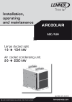
Application guide
Installation, operating and
maintenance manual
AQUALEAN AWC/AWH
Providing indoor climate comfort
MIL118E-0413 08-2013
Original manual translation
WARNING: Read this manual before installation, reparation o maintenance works.
TABLE OF CONTENTS
POINTS TO BEAR IN MIND PAGE 2
DATA PAGE FOR COMMISSIONING UNIT PAGE 3
1.- GENERAL CHARACTERISTICS
PAGE
4
5
6
6
7
7
8
9-12
13
14
15
1.1.- PRODUCT RANGE
1.2.- GENERAL DESCRIPTION
1.3.- PHYSICAL DATA
1.4.- ELECTRICAL SPECIFICATIONS
1.5.- ELECTRICAL CONNECTIONS
1.6.- OPERATING LIMITS
1.7.- FAN SPECIFICATIONS
1.8.- CAPACITY TABLES
1.9.- CORRECTION FACTORS
1.10.- DIMENSIONS
1.11.- OPTIONS
2.- INSTALLATION
2.1.- PRE - INSTALLATION
2.2.- UNIT INSTALLATION
PAGE
17
18-19
3.- COMMISSIONING AND OPERATION
3.1.- PRELIMINARY CHECKS BEFORE FIRST INSTALLATION
3.2.- PRELIMINARY CHECKS AT FIRST INSTALLATION
4.- MAINTENANCE
4.1.- PREVENTIVE MAINTENANCE
4.2.- CORRECTIVE MAINTENANCE
PAGE
20
20-21
PAGE
22
22
Lennox have been providing environmental solutions since 1895, our AQUALEAN (AWC/AWH) range continues to
meet the standards that have made LENNOX a household name. Flexible design solutions to meet your needs and
uncompromising attention to detail. Engineered to last, simple to maintain and Quality that comes as standard.
For information on local contacts at www.lennoxeurope.com.
All the technical and technological information contained in this manual, including any drawing and technical descriptions provided by us, remain the property of Lennox and must not be used (except in the operation of this product),
reproduced, issued to or made available to third parties without the prior written agreement of Lennox.
1
POINTS TO BEAR IN MIND
DANGER AND WARNING SIGNS
Abrasive
surfaces
Low
temperatures
High
temperatures
Risk of injury by
moving objects
Electrical
voltage
Risk of injury by
rotating objects
ELECTRICAL CONNECTIONS
Make sure to switch off the power before installing, repairing or carrying out maintenance on the unit,
in order to prevent serious electrical injury.
Keep local and national legislation in mind when installing the unit.
ATTENTION - WARNING
Electrical shock hazard can cause injury or death. Before attempting to perform any service or maintenance on the unit, turn OFF
the electrical power.
The air filter cleaning operations do not require technical service; however when an electrical or mechanical operation is
required call an Engineer.
FILTER CLEANING
Check the air filter and make sure it is not blocked with dust or dirt
If the filter is dirty, wash it in a bowl neutral soap and water, drying it in the
shade before inserting it in the unit.
Standard Guidelines to Lennox equipment
All technical data contained in these operating instructions, including the diagrams and technical description remains the property
of Lennox and may not be used (except for the purpose of familiarizing the user with the equipment), reproduced, photocopied,
transferred or transmitted to third parties without prior written authorization from Lennox.
The data published in the operating instructions is based on the latest information available. We reserve the right to make modifications without notice.
We reserve the right to modify our products without notice without obligation to modify previously supplied goods.
These operating instructions contain useful and important information for the smooth operation and maintenance of your equipment.
The instructions also include guidelines on how to avoid accidents and serious damage before commissioning the equipment and
during its operation and how to ensure smooth and fault-free operation. Read the operating instructions carefully before starting
the equipment, familiarize yourself with the equipment and handling of the installation and carefully follow the instructions. It is
very important to be properly trained in handling the equipment. These operating instructions must be kept in a safe place near the
equipment.
Like most equipment, the unit requires regular maintenance. This section concerns maintenance and management personnel.
If you have any queries or would like to receive further information on any aspect relating to your equipment,
do not hesitate to contact us.
2
DATA PAGE FOR UNIT COMMISSIONING
UNIT:
SERIAL Nr:
CONTROL PANEL IDENTIFICATION CODE:
INSTALLATION ADDRESS:
INSTALLER:
INSTALLER TEL:
INSTALLER ADDRESS:
DATE OF COMMISSIONING:
CHECKS:
SUPPLY VOLTAGE:
RATED VOLTAGE OF THE UNIT:
YES NO
UNIT ON SHOCK ABSORBERS
DRAINAGE WITH TRAP
MAIN POWER SUPPLY CONNECTION
CONTROL PANEL CONNECTION
COMPRESSOR OIL LEVEL INDICATOR
DATA INPUT:
COOLING CYCLE
HEATING CYCLE
Air intake temperature to the indoor coil:
Air intake temperature to the indoor coil:
High pressure:
High pressure:
Low pressure:
Low pressure:
ELECTRIC POWER CONSUMPTION (Amps)
Compressor 1
Indoor fan
Compressor
Indoor fan
Options installed:
Comments:
3
1.- GENERAL CHARACTERISTICS
1.1.- PRODUCT RANGE
A
W
C
007
S
S: 1 Circuit
C: Cooling only
H: Heat pump
Unit
AQUALEAN
N
M
1
M
Type of refrigerant
M: R-410A
---
Approximate cooling
capacity in kW
T: 230V/1/50
M: 400V/3/50
Number
of revision
COOLING ONLY UNITS
V / Ph / 50 Hz
NOMINAL CAPACITY kW
NOMINAL POWER INPUT kW
COOLING
COOLING
AWC 007
230 V - 1Ph
6.75
1.69
AWC 008
230 V - 1Ph
8
2.05
AWC 010
230 V - 1Ph
10.2
2.55
11.2
2.8
14.5
3.37
17
4.15
19
4.75
NOMINAL CAPACITY kW
NOMINAL POWER INPUT kW
MODEL
AWC 012
AWC 015
AWC 018
AWC 020
230 V - 1Ph
230 V - 3Ph
400 V - 3Ph
230 V - 3Ph
400 V - 3Ph
230 V - 3Ph
400V - 3Ph
230 V - 3Ph
400V - 3Ph
HEAT PUMP UNITS
MODEL
V / Ph / 50 Hz
AWH 007
COOLING
HEATING
COOLING
HEATING
230 V - 1Ph
6.75
8
1.69
2.1
AWH 008
230 V - 1Ph
8
9.5
2.05
2.5
AWH 010
230 V - 1Ph
10.2
12.3
2.55
3.2
11.2
13.5
2.8
3.6
AWH 012
230 V - 1Ph
400 V - 3Ph
AWH 015
400 V - 3Ph
14.5
17
3.37
4.6
AWH 018
400V - 3Ph
17
19.5
4.15
5.1
AWHW 020
400V - 3Ph
19
22
4.75
6
4
1.- GENERAL CHARACTERISTICS
1.2.-GENERAL DESCRIPTION
The air conditioner, horizontal compact, water condensed type AQUALEAN, are specially designed for small and average installation, office, house, etc.
On standard version the unit cleans, filters, cools and dehumidifies the air (AWC), and in addition heats if it is heat
pump unit (AWH). You are able to incorporate option elements such as electrical heater.
CABINET
The cabinet is made of galvanised steel with compact
dimensions and features allow the unit to be positioned in
almost any location.
Internally the unit incorporates thermal acoustic insulation.
25mm A2,s1,d0 / M0 insulation in air section
Thermal/acoustic insulation in compressor area
AIR FILTER
A polypropylene washable air filter is incorporated in the
unit it is accessible for maintenance operations.
ELECTRIC CIRCUIT
The electrical box includes all the components and terminal blocks needed for the installation. It includes a printed
board and reversible working mode in heat pump units. In
addition alarm, ON/OFF remote and dry contact for water
pump are available too.
AIR EXCHANGER
Made of copper tubing with aluminum swirl fins, they are
designed and specially dimensioned to obtain the maximum output.
REMOTE CONTROL
CLIMATIC™ 60 microprocessor based control is providing the following functions :
- 7 scheduling time zones per day over 7 days to allow
energy consumption and sound level management according to the building use and environmental constraints.-Airflow regulation to adapt unit operation to the installation requirements.
- Master/slave or cascade control of 2, up to 10 units
operating in parallel with operating time equalization and
automatic change-over in case of a unit fault.
COMPRESOR
Scroll compressor for all models, all of them with internal
thermic protection. It is mounted on vibration-absorbent
blocks both on the inside and outside, statically and dynamically balanced.
FAN
The units include a centrifugal fan motor with 3 fan
speeds management.
WATER EXCHANGER
The unit includes an exchanger plate, compact and resistant made on stainless steel, specially selected for this
type of unit.
COOLING/HEATING CIRCUIT
Made of welded dehumidifying copper tube with access
connections.
Cooling only units (AWC):
They include dehydrator filter, liquid recipient, and electronic expansion valve, high pressure switch and low
pressure transducer.
Heat pump units (AWH):
They include as expansion system an electronic expansion valve, high pressure switch and low pressure transducer. They includes a 4 ways valve and liquid receiver.
To work properly in heating mode, the unit includes check
valve, restrictor and filter drier.
OPTIONS
The unit leaves the factory with R410A refrigerant.
WATER CIRCUIT
It includes water threaded connections H-G.
5
• Electrical heater mounted on fan discharge.
• Flow switch
• Water filter.
• Main switch
• Compressor acoustic jacket
• Three phase protection (three phase units).
• Low water loop temperature
• Water diferential pressure switch
• MODBUS / BACNET / LONWORKS Communications
• DS60 Service display
• Airflow configuration
1.- GENERAL CHARACTERISTICS
1.3.- PHYSICAL DATA
AWC 007 AWC 008 AWC 010 AWC 012 AWC 015 AWC 018 AWC 020
AWH 007 AWH 008 AWH 010 AWH 012 AWH 015 AWH 018 AWH 020
UNIT MODEL
Total cooling capacity
kW (*)
6.75
8.00
10.20
11.20
14.50
17.00
19.00
Total heating capacity
kW (**)
8.00
9.50
12.30
13.50
17.00
19.50
22.00
Nominal absorbed power
Cooling
kW (*)
1.69
2.05
2.55
2.80
3.37
4.15
4.75
Nominal absorbed power
Heating
kW (**)
2.10
2.50
3.20
3.60
4.60
5.10
6.00
m3/h
1430/1010
1620/1250
2100/1550
2200/1620
2610/1850
3100/2060
3500/2450
Max. available static pressure(1)
Pa
150
125
150
150
150
150
150
Nominal water flow
l/h
1450
1730
2190
2410
3070
3640
4090
Water pressure drop
kPa
25
30
40
48
40
45
55
Net weight
Kg
69/71
70/72
109/111
111/113
113/116
148/151
148/151
dB(A)
49/51
50/52
48/51
49/51
49/53
46/51
47/54
Height
mm
441
441
491
491
491
531
531
Width
mm
886
886
1180
1180
1180
1600
1600
Depth
mm
492
492
623
623
623
703
703
1” G
1” G
1” G
1” G
1” G
1” G
1” G
Air flow (max./min.)
Cooling / heating
Sound pressure level (LP) (2) Low/High speed
Dimensions
Hydraulic connections
(*) Exchanger air inlet temperature: 27ºC DB / 19ºC WB.
Exchanger water inlet temperature: 30ºC.
(**) Exchanger air inlet temperature: 20ºC DB.
Exchanger water inlet temperature: 20ºC.
(1) With admissible minimum air flow.
(2) Sound pressure level has been tested at a distance of 2 m from
the unit, with duct in aspiration and air discharge, normal absorption in accordance with room size and unit capacity.
DB.- Dry bulb temperature
WB.- Wet bulb temperature
1.4.- ELECTRICAL SPECIFICATIONS
AWC 007 AWC 008 AWC 010 AWC 012 AWC 015 AWC 018 AWC 020
AWH 007 AWH 008 AWH 010 AWH 012 AWH 015 AWH 018 AWH 020
UNIT MODEL
1 Ph
VOLTAGE
MAXIMUM ABSORBED
POWER
MAXIMUM RUNNING
CURRENT
230V/1Ph
-
-
-
3 Ph
-
-
-
Compressor
kW
2.57
3.15
3.82
4.62 / 4.31
5.46
5.93
7.26
Indoor fan
kW
0.147
0.147
0.250
0.250
0.250
0.315
0.315
TOTAL
kW
2.72
3.30
4.07
4.87 / 4.56
5.71
6.25
7.58
Maximum
running current
A
14.4
17.6
24.6
28.6 / 10.6
12.9
14.7
17.9
Starting current
A
61.6
68.6
100.6
130.6 / 45.6
54.1
66.9
77.9
6
400V 3Ph
1.- GENERAL CHARACTERISTICS
1.5.- ELECTRICAL CONNECTIONS
3
1 - Power supply
2 - Power supply with electrical heater
3 - Connection control
EH
E.Box
1
2
FOR ELECTRICAL CONNECTION REFER TO WIRING DIAGRAM IN THE UNIT.
Nº DE CABLES X SECCION
MODEL
VOLTA
50Hz
1
2
AWC/H 007
230V / 1Ph
3 X 2,5mm²
3 X 10mm²
AWC/H 008
230V / 1Ph
3 X 2,5mm²
3 X 10mm²
AWC/H 010
230V / 1Ph
3 X 6mm²
3 X 16mm²
230V / 1Ph
3 X 6mm²
3 X 16mm²
400V / 3Ph+N
5 X 2,5mm²
5 X 6mm²
AWC/H 015
400V / 3Ph+N
5 X 2,5mm²
5 X 6mm²
AWC/H 018
400V / 3Ph+N
5 X 4mm²
5 X 10mm²
AWC/H 020
400V / 3Ph+N
5 X 4mm²
5 X 10mm²
AWC/H 012
3
5 X 1 mm² Apantallado
Local and national legislation has to be taken into account when the unit will be installed.
INSTALLATION GUIDE FOR CONTROL CABLE (TO AVOID INTERFERENCES):
• Use the screened 15 m cable supplied with terminal (3 wires + screen).
• Wire the cable separated from electrical power wiring by a physical distance of 500 mm.
• Wire the cable separated from halogen lamps/fluorescent tube lighting... by a phyisical distance of 500 mm.
• Wire the cable separated from radio frequency sources such as radio transmitter... at least 500 mm.
NEVER WIND THE REMAINING CABLE AROUND, CUT THE CABLE BY THE TERMINAL END.
1.6.- OPERATING LIMITS
Water inlet temperature
COOLING MODE
Water inlet temperature
HEATING MODE
45ºC
25ºC
22ºC
15ºC
10C
21/15ºC
32/23ºC
17ºC
Air inlet temperature into indoor section D.B/W.B
20ºC 24ºC
Air inlet temperature into indoor section D.B/W.B
WB.- Wet bulb temperature
DB.- Dry bulb temperature
7
1.- GENERAL CHARACTERISTICS
1.7.- FAN SPECIFICATIONS
AWH 007
AIR FLOW m3/h
37
50
75
100
HIGH SPEED
1430
1400
1375
1315
MEDIUM SPEED
1300
1250
1240
1185
LOW SPEED
1170
1140
1125
1070
AWH 008
AIR FLOW m3/h
1065
1050
-
1010
-
-
AVAILABLE STATIC PRESSURE Pa.
37
50
75
100
125
150
1550
1475
1395
1300
-
MEDIUM SPEED
1550
1500
1480
1420
1350
1260
-
LOW SPEED
1430
1400
1375
1315
1250
-
-
25
37
50
75
100
125
150
HIGH SPEED
2100
2075
2050
1990
1925
1850
1750
MEDIUM SPEED
1915
1900
1885
1830
1790
1700
-
LOW SPEED
1685
1680
1675
1640
1600
1550
-
25
37
50
75
100
125
150
HIGH SPEED
2200
2180
2150
2025
1925
1800
1550
MEDIUM SPEED
2025
2000
1985
1875
1775
1650
-
LOW SPEED
1825
1815
1780
1700
1620
-
-
25
37
50
75
100
125
150
HIGH SPEED
2610
2550
2480
2350
2185
2000
1750
MEDIUM SPEED
2575
2560
2450
2300
2150
1970
1730
LOW SPEED
2350
2300
2250
2150
2025
1850
-
25
37
50
75
100
125
150
HIGH SPEED
3100
2980
2960
2815
2650
2450
2210
MEDIUM SPEED
2910
2850
2800
2610
2450
2300
2100
LOW SPEED
2615
2550
2500
2375
2230
2060
-
25
37
50
75
100
125
150
HIGH SPEED
3500
3400
3300
3100
2900
2600
2300
MEDIUM SPEED
3250
3200
3100
2940
2750
2550
2300
LOW SPEED
3100
3030
3960
2815
2650
2450
-
AWH 020
AIR FLOW m3/h
1165
1125
1585
AWH 018
AIR FLOW m3/h
1245
25
AWH 015
AIR FLOW m3/h
150
1620
AWH 012
AIR FLOW m3/h
125
HIGH SPEED
AWH 010
AIR FLOW m3/h
AVAILABLE STATIC PRESSURE Pa.
25
AVAILABLE STATIC PRESSURE Pa.
AVAILABLE STATIC PRESSURE Pa.
AVAILABLE STATIC PRESSURE Pa.
AVAILABLE STATIC PRESSURE Pa.
AVAILABLE STATIC PRESSURE Pa.
8
1.- GENERAL CHARACTERISTICS
1.8.- CAPACITY TABLES
AWC/AWH 007 Nominal air flow 1.250 m3/h
Water inlet
temperature
ºC
10
15
20
25
30
35
40
Water
pressure drop
kPa
Water flow
l/h
Minimum
Nominal
Maximum
Minimum
Nominal
Maximum
Minimum
Nominal
Maximum
Minimum
Nominal
Maximum
Minimum
Nominal
Maximum
Minimum
Nominal
Maximum
Minimum
Nominal
Maximum
1010
1450
2070
1010
1450
2070
1010
1450
2070
1010
1450
2070
1010
1450
2070
1010
1450
2070
1010
1450
2070
15
25
40
15
25
40
15
25
40
15
25
40
15
25
40
15
25
40
15
25
40
COOLING CAPACITY AWC/AWH
Total capacity
EER
Sensible/Total
kW
------7,43
7,51
7,55
7,20
7,28
7,33
6,94
7,03
7,08
6,66
6,75
6,81
6,36
6,45
6,51
6,04
6,13
6,20
------6,27
6,56
6,83
5,31
5,57
5,80
4,49
4,72
4,91
3,80
4,00
4,14
3,25
3,41
3,52
2,82
2,96
3,02
HEATING CAPACITY AWH
Total capacity
Total power
kW
input kW
------0,66
0,66
0,66
0,67
0,66
0,66
0,68
0,67
0,67
0,69
0,68
0,68
0,70
0,69
0,69
0,71
0,71
0,70
6,28
6,49
6,62
7,03
7,24
7,40
7,77
8,00
8,17
8,51
8,75
8,95
-------------------
3,43
3,48
3,52
3,62
3,67
3,70
3,76
3,80
3,82
3,85
3,88
3,89
-------------------
AWC/AWH 008 Nominal air flow 1.500 m3/h
Water inlet
temperature
ºC
10
15
20
25
30
35
40
Water
pressure drop
kPa
Water flow
l/h
Minimum
Nominal
Maximum
Minimum
Nominal
Maximum
Minimum
Nominal
Maximum
Minimum
Nominal
Maximum
Minimum
Nominal
Maximum
Minimum
Nominal
Maximum
Minimum
Nominal
Maximum
1210
1730
2470
1210
1730
2470
1210
1730
2470
1210
1730
2470
1210
1730
2470
1210
1730
2470
1210
1730
2470
20
30
50
20
30
50
20
30
50
20
30
50
20
30
50
20
30
50
20
30
50
COOLING CAPACITY AWC/AWH
Total capacity
EER
Sensible/Total
kW
------8,85
8,95
9,01
8,55
8,65
8,71
8,23
8,33
8,40
7,90
8,00
8,07
7,55
7,65
7,73
7,18
7,29
7,37
------5,86
6,09
6,30
5,05
5,26
5,45
4,34
4,54
4,69
3,73
3,90
4,03
3,21
3,36
3,46
2,78
2,91
2,98
HEATING CAPACITY AWH
Total capacity
Total power
kW
input kW
------0,66
0,65
0,65
0,66
0,66
0,66
0,67
0,67
0,67
0,68
0,68
0,68
0,69
0,69
0,69
0,70
0,70
0,70
Nominal capacity conditions: Exchanger air inlet temperature: 27ºC DB/19ºC WB for cooling y 20ºC WB for heating mode.
(DW:dry bulb WB:wet bulb)
For another working conditions use correction factor tables.
9
7,56
7,79
7,93
8,41
8,65
8,81
9,25
9,50
9,68
10,08
10,34
10,55
-------------------
3,43
3,47
3,51
3,59
3,63
3,66
3,72
3,75
3,77
3,79
3,82
3,83
-------------------
1.- GENERAL CHARACTERISTICS
1.8.- CAPACITY TABLES
AWC/AWH 010 Nominal air flow 1.900 m3/h
Water inlet
temperature
ºC
10
15
20
25
30
35
40
Water
pressure drop
kPa
Water flow
l/h
Minimum
Nominal
Maximum
Minimum
Nominal
Maximum
Minimum
Nominal
Maximum
Minimum
Nominal
Maximum
Minimum
Nominal
Maximum
Minimum
Nominal
Maximum
Minimum
Nominal
Maximum
1530
2190
3130
1530
2190
3130
1530
2190
3130
1530
2190
3130
1530
2190
3130
1530
2190
3130
1530
2190
3130
25
40
65
25
40
65
25
40
65
25
40
65
25
40
65
25
40
65
25
40
65
COOLING CAPACITY AWC/AWH
Total capacity
EER
Sensible/Total
kW
------11,19
11,30
11,37
10,85
10,97
11,04
10,48
10,60
10,68
10,07
10,20
10,29
9,63
9,76
9,86
9,15
9,29
9,39
------6,05
6,29
6,53
5,20
5,42
5,62
4,46
4,66
4,83
3,83
4,00
4,14
3,30
3,45
3,56
2,89
3,01
3,09
HEATING CAPACITY AWH
Total capacity
Total power
kW
input kW
------0,68
0,67
0,67
0,68
0,68
0,68
0,69
0,69
0,69
0,70
0,70
0,70
0,72
0,71
0,71
0,73
0,73
0,72
9,77
10,06
10,24
10,85
11,17
11,39
11,96
12,30
12,55
13,10
13,46
13,75
-------------------
3,56
3,60
3,64
3,73
3,77
3,80
3,86
3,90
3,92
3,96
3,99
4,01
-------------------
AWC/AWH 012 Nominal air flow 2.000 m3/h
Water inlet
temperature
ºC
10
15
20
25
30
35
40
Water
pressure drop
kPa
Water flow
l/h
Minimum
Nominal
Maximum
Minimum
Nominal
Maximum
Minimum
Nominal
Maximum
Minimum
Nominal
Maximum
Minimum
Nominal
Maximum
Minimum
Nominal
Maximum
Minimum
Nominal
Maximum
1690
2410
3440
1690
2410
3440
1690
2410
3440
1690
2410
3440
1690
2410
3440
1690
2410
3440
1690
2410
3440
30
48
75
30
48
75
30
48
75
30
48
75
30
48
75
30
48
75
30
48
75
COOLING CAPACITY AWC/AWH
Total capacity
EER
Sensible/Total
kW
------12,37
12,50
12,59
11,96
12,10
12,18
11,52
11,66
11,75
11,06
11,20
11,30
10,57
10,71
10,82
10,06
10,20
10,31
------6,05
6,29
6,50
5,20
5,42
5,61
4,46
4,66
4,82
3,83
4,00
4,13
3,29
3,45
3,55
2,87
3,00
3,07
------0,66
0,66
0,66
0,67
0,67
0,67
0,68
0,68
0,67
0,69
0,68
0,68
0,70
0,70
0,69
0,71
0,71
0,71
HEATING CAPACITY AWH
Total capacity
Total power
kW
input kW
Nominal capacity conditions: Exchanger air inlet temperature: 27ºC DB/19ºC WB for cooling y 20ºC WB for heating mode.
(DW:dry bulb WB:wet bulb)
For another working conditions use correction factor tables.
10
10,74
11,05
11,25
11,94
12,26
12,50
13,15
13,50
13,77
14,38
14,75
15,05
-------------------
3,52
3,56
3,59
3,67
3,70
3,72
3,77
3,80
3,81
3,84
3,86
3,87
-------------------
1.- GENERAL CHARACTERISTICS
1.8.- CAPACITY TABLES
AWC/AWH 015 Nominal air flow 2.450 m3/h
Water inlet
temperature
ºC
10
15
20
25
30
35
40
Water
pressure drop
kPa
Water flow
l/h
Minimum
Nominal
Maximum
Minimum
Nominal
Maximum
Minimum
Nominal
Maximum
Minimum
Nominal
Maximum
Minimum
Nominal
Maximum
Minimum
Nominal
Maximum
Minimum
Nominal
Maximum
2150
3070
4390
2150
3070
4390
2150
3070
4390
2150
3070
4390
2150
3070
4390
2150
3070
4390
2150
3070
4390
25
40
60
25
40
60
25
40
60
25
40
60
25
40
60
25
40
60
25
40
60
COOLING CAPACITY AWC/AWH
Total capacity
EER
Sensible/Total
kW
HEATING CAPACITY AWH
Total capacity
Total power
kW
input kW
COOLING CAPACITY AWC/AWH
Total capacity
EER
Sensible/Total
kW
HEATING CAPACITY AWH
Total capacity
Total power
kW
input kW
------16,02
16,20
16,31
15,49
15,67
15,79
14,92
15,10
15,23
14,32
14,50
14,63
13,68
13,87
14,00
13,01
13,20
13,34
------6,41
6,67
6,89
5,56
5,79
5,98
4,79
5,00
5,17
4,11
4,30
4,44
3,51
3,69
3,80
3,01
3,17
3,26
------0,67
0,67
0,67
0,68
0,67
0,67
0,68
0,68
0,68
0,70
0,69
0,69
0,71
0,70
0,70
0,72
0,72
0,71
13,59
13,99
14,26
15,06
15,49
15,80
16,54
17,00
17,35
18,04
18,52
18,92
-------------------
3,39
3,43
3,46
3,54
3,58
3,61
3,66
3,70
3,72
3,76
3,79
3,81
-------------------
AWC/AWH 018 Nominal air flow 2.800 m3/h
Water inlet
temperature
ºC
10
15
20
25
30
35
40
Water
pressure drop
kPa
Water flow
l/h
Minimum
Nominal
Maximum
Minimum
Nominal
Maximum
Minimum
Nominal
Maximum
Minimum
Nominal
Maximum
Minimum
Nominal
Maximum
Minimum
Nominal
Maximum
Minimum
Nominal
Maximum
2540
3640
5200
2540
3640
5200
2540
3640
5200
2540
3640
5200
2540
3640
5200
2540
3640
5200
2540
3640
5200
30
45
70
30
45
70
30
45
70
30
45
70
30
45
70
30
45
70
30
45
70
------18,55
18,72
18,81
18,03
18,21
18,31
17,44
17,63
17,75
16,80
17,00
17,14
16,09
16,31
16,46
15,33
15,55
15,72
------5,86
6,07
6,25
5,15
5,34
5,50
4,51
4,69
4,83
3,93
4,10
4,22
3,43
3,58
3,68
3,00
3,13
3,21
------0,66
0,66
0,66
0,67
0,66
0,66
0,67
0,67
0,67
0,68
0,68
0,68
0,69
0,69
0,69
0,70
0,70
0,70
Nominal capacity conditions: Exchanger air inlet temperature: 27ºC DB/19ºC WB for cooling y 20ºC WB for heating mode.
(DW:dry bulb WB:wet bulb)
For another working conditions use correction factor tables.
11
15,55
16,00
16,28
17,25
17,73
18,07
18,98
19,50
19,89
20,74
21,30
21,75
-------------------
3,36
3,42
3,45
3,56
3,62
3,65
3,75
3,80
3,84
3,91
3,96
4,00
-------------------
1.- GENERAL CHARACTERISTICS
1.8.- CAPACITY TABLES
AWC/AWH 020 Nominal air flow 3.100 m3/h
Water inlet
temperature
ºC
10
15
20
25
30
35
40
Water flow
l/h
Minimum
Nominal
Maximum
Minimum
Nominal
Maximum
Minimum
Nominal
Maximum
Minimum
Nominal
Maximum
Minimum
Nominal
Maximum
Minimum
Nominal
Maximum
Minimum
Nominal
Maximum
Water
pressure drop
kPa
2860
4090
5840
2860
4090
5840
2860
4090
5840
2860
4090
5840
2860
4090
5840
2860
4090
5840
2860
4090
5840
35
55
80
35
55
80
35
55
80
35
55
80
35
55
80
35
55
80
35
55
80
COOLING CAPACITY AWC/AWH
Total capacity
EER
Sensible/Total
kW
------20,89
21,12
21,25
20,23
20,46
20,60
19,52
19,75
19,90
18,76
19,00
19,16
17,96
18,20
18,36
17,11
17,36
17,53
------5,68
5,88
6,04
5,01
5,20
5,34
4,40
4,57
4,70
3,83
4,00
4,11
3,33
3,48
3,58
2,88
3,02
3,10
HEATING CAPACITY AWH
Total capacity
Total power
kW
input kW
------0,65
0,65
0,65
0,66
0,66
0,66
0,67
0,67
0,66
0,68
0,67
0,67
0,69
0,68
0,68
0,70
0,69
0,69
17,65
18,13
18,45
19,53
20,06
20,42
21,44
22,00
22,42
23,37
23,97
24,44
-------------------
3,43
3,46
3,48
3,54
3,57
3,58
3,63
3,65
3,66
3,69
3,71
3,72
-------------------
Nominal capacity conditions: Exchanger air inlet temperature: 27ºC DB/19ºC WB for cooling y 20ºC WB for heating mode.
(DW:dry bulb WB:wet bulb)
For another working conditions use correction factor tables.
Dissipated heat for cooling mode:
The heat to dissipate in the water exchanger for cooling mode is near to: Total capacity + total power input.
Absorbed heat for heating mode:
The heat absorbed in the water exchanger for heating mode is near to: Total capacity - total power input.
Water pressure drop has been calculated without water filter an option. With this option, the water pressure drop
(kPa) is:
WATER PRESSURE DROP WITH WATER FILTER AWC/AWH
AWC 007 AWC 008 AWC 010 AWC 012 AWC 015 AWC 018 AWC 020
AWH 007 AWH 008 AWH 010 AWH 012 AWH 015 AWH 018 AWH 020
UNIT
Water flow
Minimum
l/h
20
25
30
35
35
40
45
Nominal
l/h
30
35
50
55
55
60
75
Maximum
l/h
45
60
80
90
80
100
115
12
1.- GENERAL CHARACTERISTICS
1.9.- CORRECTION FACTORS
AIR FLOW
The data in the capacity tables, have been calculated for nominal air flow; with maximum/minimum air flows use these correction
factors:
UNITS
ACW 007
ACW 008
ACW 010
ACW 012
ACW 015
ACW 018
ACW 020
COOLING
AIR FLOW
HEATING
Total capacity
kW
Sensible
capacity kW
Total power
input kW
Total capacity
kW
Total power
input kW
Maximun
1430
1,02
1,06
1,02
1,02
0,96
Nominal
1250
1,00
1,00
1,00
1,00
1,00
Minimum
1010
0,96
0,92
0,97
0,99
1,08
Maximun
1620
1,01
1,03
1,01
1,01
0,98
Nominal
1500
1,00
1,00
1,00
1,00
1,00
Minimum
1250
0,96
0,93
0,98
0,98
1,06
Maximun
2100
1,02
1,04
1,03
1,01
0,98
Nominal
1900
1,00
1,00
1,00
1,00
1,00
Minimum
1550
0,96
0,92
0,98
0,97
1,07
Maximun
2200
1,02
1,03
1,03
1,01
0,98
Nominal
2000
1,00
1,00
1,00
1,00
1,00
Minimum
1620
0,96
0,92
0,98
0,97
1,09
Maximun
2610
1,01
1,03
1,01
1,01
0,98
Nominal
2450
1,00
1,00
1,00
1,00
1,00
Minimum
1850
0,94
0,89
0,97
0,96
1,12
Maximun
3100
1,01
1,03
1,01
1,01
0,98
Nominal
2800
1,00
1,00
1,00
1,00
1,00
Minimum
2060
0,92
0,87
0,97
0,95
1,12
Maximun
3500
1,01
1,03
1,02
1,01
0,98
Nominal
3100
1,00
1,00
1,00
1,00
1,00
Minimum
2450
0,94
0,89
0,98
0,96
1,12
AIR INLET
COOLING MODE AWC/AWH. The data in the capacity tables has
been calculated for air inlet temperature: 27ºC DB and 19ºC WB.
For another conditions use these correction factors.
Air inlet
temperature
(D.B.)
Air inlet
temperature
(W.B.)
21
15
24
17
TC (kW)
0,88
Air inlet
temperature
(D.B.)
SC (kW)
0,89
15
Power input (kW)
0,99
TC (kW)
0,94
SC (kW)
27
19
32
21
23
17
0,94
Power input (kW)
1,00
TC (kW)
1,00
SC (kW)
29
HEATING MODE AWH. The data in the capacity tables
has been calculated for air inlet temperature: 20ºC DB. For
another conditions use these correction factors.
20
22
1,00
Power input (kW)
1,00
TC (kW)
1,07
SC (kW)
0,99
Power input (kW)
1,00
TC (kW)
1,13
SC (kW)
1,04
Power input (kW)
1,01
24
TC (kW)
1,03
Power input (kW)
0,91
TC (kW)
1,02
Power input (kW)
0,95
TC (kW)
1,00
Power input (kW)
1,00
TC (kW)
0,99
Power input (kW)
1,04
TC (kW)
0,98
Power input (kW)
1,08
TC: Total capacity
SC: Sensible capacity
D.B.: Dry bulb
W.B.: Wet bulb
13
1.- CARACTERÍSTICAS GENERALES
1.10.- DIMENSIONS
20
163,5
239,5
89
9
23,5
213,5
126,5
100
792
10
40
363
40
80
9
53
269,3
25
8
COMPRESSOR
COIL
AIR FILTER
WATER EXCHANGER
ELECTRICAL BOX
DRIP TRAY
INLET WATER
OUTLET WATER
POWER SUPPLY
DRAINAGE TUBE
STANDARD
OPTION
1
2
3
4
5
6
7
8
AWC/AWH 007-008
89
7
64,7
886,2
18,3
829,4
18,3
500
231,9
32,5
60
3
4
2
6
492
427
10
1
32,5
5
792
AWC/AWH 010-012-015
20
271
91
15
261
23,5
294,5
404
1083
25
180,3
105
9
37
269,3
25
8
7
88
59,3
1180
25
1130
60,6
25
699
323,4
23
2
3
2
4
6
623
577
10
1
23
5
1083
7
128,5
338,5
23,5
505
25
236
1503
294,5
447
34
20
176,5
269
127
9
25
8
34
AWC/AWH 018-020
90
98,5
1600
25
25
1550
1082
359,8
23
61,2
2
3
4
657
703
6
10
1
23
5
1503
14
1.- GENERAL CHARACTERISTICS
1.11.- OPTIONS
COMPRESSOR ACOUSTIC JACKET
Each compressor is fitted with a compressor acoustic jacket this provides attenuation of the compressor noise that
radiates from the unit when in operation.
THREE PHASE PROTECTION (THREE PHASE UNITS)
Located at the electrical box of the unit, it assures that unit will not begin operation if connection phases of compressor
are not correct. Should this occur, then just switch two phase connections.
ELECTRICAL HEATERS
COOLING MODE AWC/AWH
UNIT
007
008
010
012
015
018
020
Standard
2
3 (1F-3F)
5
Medium
5
5(1F-3F)
9
High
9 (3F)
12
HEATING MODE AWH
UNIT
Standard
007
008
2
010
012
015
3 (1F-3F)
018
020
5
Electrical
heater
INSTALLATION
Supply sensor is delivered outside the unit and not fixed when electrical heater is selected as option.
It should be installed in the duct using the sheet metal fixation delivered with the unit. See picture below for the installation.
350
WATER FILTER
This option is supplied loose.
The water filter must be fitted in the water inlet of the unit, it protects the unit against particles (greater than 1 mm)
getting inside the water circuit, and prevents the water interchanger gets dirty.
With water filter water pressure drop has a different value (see table page 12).
FLOW SWITCH
This option is supplied loose.
The flow switch stops the unit if water flow is lower than the minimum.
15
1.- GENERAL CHARACTERISTICS
1.11.- OPTIONS
MAIN SWITCH
The main switch is equipped with a gadget, which allows opening the panel of the electrical box, when it is on OFF
position.
Verify that the main switch is large enough to handle the current for the unit.
LOW WATER LOOP TEMPERATURE
Addition of a 3-way valve and high pressure transducer to operate the unit below 15°C (down to 0°C).
The controler will monitor the 3-way valve.
The 3-way valve is supplied loose (pressure transducer factory mounted).
WATER DIFERENTIAL PRESSURE SWITCH
This option is supplied loose.
The differential pressure switch stops the unit if there is not water flow.
MODBUS / BACNET / LONWORKS COMMUNICATION
The control board is equipped with a RS485 serial communication port to allow remote management through communication bus.
According to the wished communication protocol, our control board can be fi tted with ModBUS®, LonWorks® or BacNET® communication interface
DS60 (Service display)
This display provides access to the full controler menu to set all parameters.
24V customer display located at 30 meters maximum from the unit. Remote customer parameter reading and
modification
Service
Display
AIRFLOW CONFIGURATION
Supply airflow configuration can be changed on site.
For models AWC / AWH 018-020 additional sheet metal and support for the fan are not needed.
See picture below for airflow configuration
Option
Standard
16
2.- INSTALLATION
2.1.- PRE - INSTALLATION
Prior to install the equipment, make sure of the following points:
• Leave enough space for access to air supply, water section, power supply and condensed outlet.
• The water section must have the correspondent valves.
• Easy extraction of the air filter.
• Easy access to lateral panel for easy accessibility to all services of the unit.
• Unit must be mounted with antivibration.
• The electrical section must be done following legal normative
• Check that the tension is the same as installation place.
• Keep in mind power supply for maximum consumption for each unit.
• Check water quality, across analysis according to local normative. If quality of water is not good, it may be necessary to install a device to decalcify.
• The water must be analysed; the water circuit installed must include all items necessary for treatment of the water:
filters, additives, intermediate exchangers, bleed valves, vents, isolating valves etc... depending on the results of the
water analysis.
We do not advise operation of the units with open loops which can cause problems with oxygenation, or
operation with untreated ground water.
Use of untreated or improperly treated water can cause deposits of scale, algae and sludge or cause corrosion and
erosion. It is advisable to call in a qualified water treatment specialist to determine what kind of treatment will be
necessary. The manufacturer cannot accept liability for damage caused by the use of untreated or improperly treated
water, salt water or brine.
Here are our non exhaustive recommendations given as an indication:
• No NH4+ ammonium ions in the water, they are very detrimental for copper. <10mg/l
• Cl- Chloride ions are detrimental for copper with a risk of perforations by corrosion by puncture. < 10 mg/l.
• SO42- sulphate ions can cause perforating corrosion.< 30 mg/l.
• No fluoride ions (<0.1 mg/l).
• No Fe2+ and Fe3+ ions with dissolved oxygen. Dissolved iron < 5 mg/l with dissolved oxygen < 5 mg/l. Over
those values, it means a corrosion of steel which may generate a corrosion of copper parts under deposite of Fe –
this is mainly the case with shell and tube heat exchangers.
• Dissolved silicon: silicon is an acid element of water and can also lead to corrosion risks. Content < 1mg/l.
• Water hardness: TH >2.8 K. Values between 10 and 25 can be recommended. This will facilitate scale deposit
that can limit corrosion of copper. TH values that are too high can cause piping blockage over time.
• TAC< 100.
• Dissolved oxygen: Any sudden change in water oxygenation conditions must be avoided. It is as detrimental to
deoxygenate the water by mixing it with inert gas as it is to over-oxygenate it by mixing it with pure oxygen. The
disturbance of the oxygenation conditions encourages destabilisation of copper hydroxides and enlargement of
particles.
• Specific resistance – electric conductivity: the higher the specific resistance, the slower the corrosion tendency.
Values above 3000 Ohm/cm are desirable. A neutral environment favours maximum specific resistance values.
For electric conductivity values in the order of 200-6000 S/cm can be recommended.
• pH: pH neutral at 20°C (7 < pH < 8)
It is very important that the unit works with water flows between maximum and minimum values according to the tables. You
have to calculate water pump and install regulation valve if they are needed, in order to be sure that the unit works with water
flow values indicated in the tables. Specially for heat pump units AWH in heating mode, if the unit works with water flow below
specified values, the unit can be seriously damaged, water exchanger can be frozen.
17
2.- INSTALLATION
2.2.- UNIT INSTALLATION
• Las unidades deben ser instaladas por personal cualificado.
Make sure to disconnect power supply before carrying out any type of work on the unit.
Hidraulic circuit:
• Make sure that water connections are correct, water inlet (down side), water outlet (upper side).
Water filter in the inlet water connection has to be used. The step of the mesh should be less
than Å 1.5 mm which avoids welded and dirty get to the unit.
Lennox offers this element as an option.
• Install cut off valves at inlet and outlet water connections, because of in case of repairs, the hydraulic circuit can be
independent.
Use flexible components for the hydraulic connection between the unit and the installation in
order to prevent the transmission of vibrations.
• Install water inlet and water outlet connections with a differential gauge device in order to see the pressure difference
between
the outlet an inlet connections.
• At the end Install an adequate water pump, and all the necessary elements for the installation
AIR FLOW:
Airflow can be adjusted though the unit remote display between maximum/nominal/minimum
With “AUTO” the controller regulates the airflow between maximun and minimum values to assure the correct unit
operation mode.
DRAINAGE TUBE
• Use the flexible tube connected to the drip tray as a drainage tube. Cause a siphon with this tube in order to avoid
the inlet of scents from the installation to the unit.
Install a siphon from the drainage tube of the drip tray with a difference in height of 80 mm to prevent from not evacuating due to the negative pressure created by the fans. The pipe will slope down 2% to make it easier for the condensates to drain off.
Min. 80mm
2%
Inspection and
cleaning stopper.
18
2.- INSTALLATION
2.2.- UNIT INSTALLATION
INSTALLATION PROCESS
• After supply the power to the unit and connect inlet/outlet water:
- Connect the gauges in high pressure and low pressure side.
- Use a temperature probe in the compressor gas pipe and another ones in the inlet and outlet water pipes.
- Start water pump.
- Make sure to close the unit all panels have to be correctly situated.
- Start the unit and make sure that the thermostat temperature adjustment is correct.
- Check the correct water flow with a differential gauge device connected between the inlet and outlet water connections in order to know the pressure difference. Check it according to the capacity table values.
In addition, you can know the correct water flow with Dt measurement (inlet temperature ºC - outlet temperature
ºC).
This value has to be the same as the value calculated with this formula:
a) Cooling mode
[Cooling capacity (kW) + Total power input (kW)] x 860
∆t =______________________________________________
Water flow (l/h)
a) Heating mode
[Heating capacity (kW) + Total power input (kW)] x 860
∆t = ____________________________________________
Water flow (l/h)
All the data water flow, cooling / heating capacity and power input are on the capacity tables according to each
model and the working conditions.
• After a few minutes, when the unit will be stabilised, you have to verify:
- High and low pressure values and in addition saturation temperatures according to the correct working mode of
the unit.
- Gas reheating values are below 12ºC.
If it is not correct, please check expansion system and refrigerant leaks.
If the compressor noise is very high and in addition, high and low pressure values are similar,
it can be possible a wrong phase electrical connection. In this case, please change the
connection for two phases.
- Outlet and inlet water temperature are correct according to the water flow which is between specified values.
• After verify the correct working mode, please stop the unit, disconnect the gauges and temperature probes. and
clean water filter.
The unit can be work properly until next maintenance revision.
19
3.- COMMISSIONING AND OPERATION
3.1.- PRELIMINARY CHECKS BEFORE STARTUP
- Check that the power supply is the same as stated on the Rating Plate which is in agreement with the electrical diagram for the unit and that cable sizes are correct.
- Check that tightness of the electrical connections to their terminals and to ground.
- Check with your hand that the fans are turning freely.
- Check the control panel connections.
(If the connection is incorrect, the unit will not operate and the control panel display will not light).
3.2.- PRELIMINARY CHECKS AT STARTUP
To start the unit, follow the instructions given in the User Manual for the control supplied with the unit
(requiring operation in any of the modes, cooling, heating, or automatic).
After a time delay, the unit will start.
With the unit operating, check that the fans are turning freely and in the correct direction.
CHECK THAT THE COMPRESSOR IS ROTATING IN THE CORRECT DIRECTION.
- If you have the option phase rotation indicator, use it to check the correct rotation.
- If you do not have three phase return lock, check the correct direction of rotation. The suction pressure decreases and the discharge
pressure increases when the compressor is started.
- If the connection is incorrect, rotation will be reversed, causing a high noise level and a reduction in the amount of current consumed.
If this occurs, the compressor’s internal protection system will operate to shut down the unit. The solution is to disconnect, reverse
two of the phases and connect again.
WITH OPERATING UNIT, CHECK:
- Low pressure and high pressure.
- Use the evaporating and liquid temperature to calculate superheat and subcooling.
- Adjust the refrigerant charge and/or expansion valve according to the preceding values.
COMPRESSOR OIL LEVEL
The oil level must always be checked. When the compressor is at rest, the level should be between 1/4 and 3/4
in the sight glass, while when running the level should be between 3/4 and full.
In the event of having to add oil, remember the type of oil is synthetic POE.
The original oil charge in the compressor is ICI Emkarate RL32-3MAF. This type of oil must also be used when replacing the oil
completely.
When only topping up, RL32-3MAF or Mobil EAC Artic 22C can be used.
20
3.- COMMISSIONING AND OPERATION
3.2.- PRELIMINARY CHECKS AT STARTUP
The unit must be installed in accordance with local safety codes andregulations and can only be used in a well
ventilated area. Please readcarefully the manufacturer’s
instructions before starting this unit
All work on the unit must be carried out by a qualified
and authorised employee.
Non-compliance with the following instructions may result
in injury or serious accidents.
Work on the unit:
The unit shall be isolated from the electrical supply by disconnection and locking using the main isolating switch.
Workers shall wear the appropriate personal protective
equipment (helmet, gloves, glasses,etc.).
Electrical system:
Electrical connections can become loose during transport. Please check them before starting-up the unit Compressors with specific rotation direction. Check the correct
rotation direction of the fan before closing the compressor
circuit breakers. If the direction is incorrect, the phases
must be reversed at the head of the main switch. Work on
electric components shall be performed with the power off
(see below) by employees having valid electrical qualification and authorisation.
Refrigerating circuit(s):
After more than 12 hours of power cut, the cranckcase
heater (compressor) should be powered for 5 hours before any return to service. Non-compliance with this instruction can cause deterioration of the compressors.
Monitoring of the pressures, draining and filling of the system under pressure shall be carried out using connections
provided for this purpose and suitable equipment.
21
To prevent the risk of explosion due to spraying of coolant and oil, the relevant circuit shall be drained and
at zero pressure before any disassembly or unbrazing
of the refrigerating parts takes place.
There is a residual risk of pressure build-up by degassing the oil or by heating the exchangers after the circuit
has been drained. Zero pressure shall be maintained
by venting the drain connection to the atmosphere on
the low pressure side.
The brazing shall be carried out by a qualified brazier.
The brazing shall comply according to code ASME section IX following the procedures specific.
Before starting up
-Test the circuit to the maximum working pressure(see
the nameplate)
-Verifify the operation of the high pressure swich.
-Check the piping and the components of the refrigerant
circuit.
Replacing components:
In order to maintain CE marking compliance, replacement of components shall be carried out
using spare parts, or using parts approved by Lennox.
Only the coolant shown on the manufacturer’s nameplate shall be used, to the exclusion of all other
products (mix of coolants, hydrocarbons, etc.).
CAUTION:
In the event of fire, refrigerating
circuits can cause an explosion
and spray coolant gas and oil.
4.- MAINTENANCE
4.1.- PREVENTIVE MAINTENANCE
PREVENTIVE MAINTENANCE PREVENTS COSTLY REPAIRS.
THIS REQUIRES PERIODIC INSPECTIONS:
- GENERAL STATE OF THE CASING:
Furniture, paint, damage due to shocks, rust spots, levelling and supporting, condition of the shock absorbers, if installed, screwed panels, etc.
- ELECTRICAL CONNECTIONS:
State of hoses, tightness of screws, earthing, current consumption of the compressor and fans and check that the unit is receiving the correct voltage.
- COOLING CIRCUIT:
Check that the pressures are correct and that there are no leaks. Check that there is no damage to the pipe insulation, that the condition of the coils
is good and that they are not blocked by bits of paper or plastic drawn in by the air flow, etc.
- COMPRESSOR:
If a sight glass is fitted, check the oil level.
Check the condition of the silentbloc mountings.
- FANS:
Check that fans turn freely and in the correct direction without excessive noise.
- CONTROL:
Check Set Points and normal operation.
4.2.- CORRECTIVE MAINTENANCE
IMPORTANT
MAKE SURE THAT THE UNIT IS FULLY DISCONNECTED FROM THE POWER SUPPLY WHEN CARRYING OUT
ANY TYPE OF WORK ON THE MACHINE.
If any component in the cooling circuit is to be replaced, follow these recommendations:
- Always use original replacement parts.
- If the component can be isolated, it is not necessary to remove the entire refrigerant charge, if the component cannot be isolating and the refrigerant charge is removed, it should be removed through the Schrader valves located in the outdoor section. Create a slight vacuum as a safety
measure.
- Regulation prohibits the release of refrigerant into the atmosphere.
- If cuts must be made in the pipe work, use pipe cutters. Do not use saws or any other tools that produce filings.
- All brazing must be carried out in a nitrogen atmosphere to prevent corrosion forming.
- Use silver alloy brazing rod.
- Take special care that the flame from the torch is directed away from the component to be welded and cover with a wet rag to prevent overheating.
Direction of the flame
Silver alloy welding rod
Wet rag
Nitrogen
Component to be welded
- Take very special care if 4-way or check valves are to be replaced since these have internal components that are very heat-sensitive such as plastic, teflon, etc.
- If a compressor is to be replaced, disconnect it electrically and un-braze the suction and discharge lines. Remove the securing screws and
replace the old compressor with the new one. Check that the new compressor has the correct oil charge, screw it to the base and connect the lines
and electrical connections.
- Evacuate above and below through the Schrader valves of the outdoor unit until -750 mm Hg is reached.
Once this level of vacuum has been reached, keep the pump running for at least one hour.
DO NOT USE THE COMPRESSOR AS A VACUUM PUMP.
- Charge the unit with refrigerant according to the data on the Rating Plate for the unit and check that there are no leaks.
PRECAUTIONS TO BE TAKEN WHEN USING OF R-410A Refrigerant:
R-410A refrigerant is used in the unit; the following standard precautions for this gas should therefore be taken:
- The Vacuum Pump must have a Check Valve or Solenoid Valve fitted.
- Pressure Gauges and Hoses for exclusive use with R-410A Refrigerant should be used.
- Charging should be carried out in the Liquid Phase.
- Always use scales to weigh-in charge
- Use the Leak Detector exclusive for R-410A Refrigerant.
- Do not use mineral oil, only synthetic oil to ream, expand or make connections.
- Keep pipes wrapped before using them and be very thorough about any possible dirt (dust, filings, burrs, etc.).
- When there is a leak, collect what remains of the charge, create a vacuum in the unit and completely recharge with new R-410A Refrigerant.
- Brazing should always be carried out in a nitrogen atmosphere.
- Reamers should always be well sharpened.
22
www.lennoxeurope.com
BELGIUM, LUXEMBOURG
www.lennoxbelgium.com
PORTUGAL
www.lennoxportugal.com
Due to Lennox’s ongoing commitment to quality,
the Specifications, Ratings and Dimensions are
subject to change without notice and without
incurring liability.
CZECH REPUBLIC
www.lennox.cz
RUSSIA
www.lennoxrussia.com
Improper
installation,
adjustment,
alteration,
service or maintenance can cause property
damage or personal injury.
Installation and service must be performed by a
FRANCE
www.lennoxfrance.com
SLOVAKIA
www.lennoxdistribution.com
GERMANY
www.lennoxdeutschland.com
SPAIN
www.lennoxspain.com
GREAT BRITAIN
www.lennoxuk.com
UKRAINE
www.lennoxrussia.com
NETHERLANDS
www.lennoxnederland.com
OTHER COUNTRIES
www.lennoxdistribution.com
POLAND
www.lennoxpolska.com
MIL118E-0413 08-2013
Original manual translation
qualified installer and servicing agency.