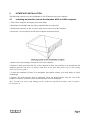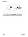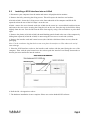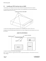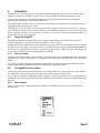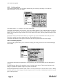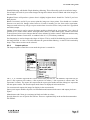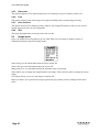
1
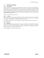
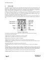
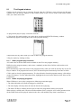
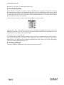
SCSI
(inc CDFS)
USER GUIDE
for use on all Acorn RISC OS computers
SCSI
(inc CDFS)
USER GUIDE
for use on all Acorn RISC OS computers (except A4)
Published by Castle Technology
Issue 6th October 1997
SCSI User Guide
Copyright © 1994/5/6/7 Castle Technology
All rights reserved
SCSI
Copyright © 1989/97 Castle Technology
All rights reserved
CDFS
Copyright © 1990, 1991 Next Technology Corporation Limited.
All rights reserved.
Copyright © 1993 Acorn Computers Limited.
All rights reserved.
All trademarks acknowledged
No part of this book may be reproduced by any means without the prior written consent of the
copyright holder. The only exceptions are as provided for by the Copyright (photocopying) Act or for
the purpose of review.
Ore Trading Estate Woodbridge Road Framlingham Suffolk IP13 9LL UK
Telephone: (Sales) 01728 621222 (Support) 01728 621631 Facsimile: 01728 621179
e-mail: [email protected] or [email protected]
web: http://www.castle-technology.co.uk
SCSI
1.1
1.2
1.3
Contents
Introduction
Typographical conventions
Getting Started
Page
3
3
3
2
2.1
2.2
2.3
2.4
2.5
INTERFACE INSTALLATION
Installing an Interface into an Archimedes
Installing a SCSI interface into an A30x0
Installing an SCSI interface into an A4000
Installing an SCSI interface into an A5000
Installing a SCSI interface into a Risc PC
4
4
6
7
9
11
3
3.1
3.2
3.3
3.4
3.5
3.6
ADDING SCSI DEVICES
Termination
SCSI ID's
External SCSI devices
Internal SCSI devices in the Archimedes
Internal devices in the A5000
Internal devices in the RISC PC.
12
12
13
13
14
15
16
4
4.1
4.1.1
4.1.2
4.1.3
4.2
4.3
4.4
4.5
SCSI CONFIGURATION AND SOFTWARE
!Setup
SCSI Devices window
SCSI Disc Management window
Harddisc Formatting window
*Devices
Configuring your computer manually
SCSI from the desktop
Debugging
17
17
17
18
19
20
21
22
22
5
INTRODUCTION
25
6
6.1
6.1.1
6.1.2
6.1.3
CONFIGURING THE COMPUTER
Setting up PC Soft to read CD-ROM discs
Loading PC Soft
Loading the MS-DOS CD-ROM support software
Recommended changes to configuration files
25
26
26
26
27
7
7.1.1
7.1.2
7.1.3
7.2
7.2.1
7.2.2
7.2.3
USING CD-ROM DISCS
Using CDFS
If you are not using CDFS
Reading PC-format CD-ROM discs using PC Soft
Performance limitations
VGA images
Sound
Windows
28
28
28
28
29
29
29
29
8
8.1
CDPLAYER
The Keypad window
30
31
CDFS
8.1.1
8.1
8.1.1
8.1.2
8.2
8.3
Other program play functions
The Keypad window
Other program play functions
Notes on playing programs
The Setup window
Quitting CDPlayer
31
31
31
31
32
32
9
9.1
9.1.1
9.2
9.2.1
9.2.2
9.2.3
9.2.4
9.2.5
9.2.6
9.2.7
9.2.8
9.3
CHANGEFSI
Using ChangeFSl
Picture formats
ChangeFSl in more detail
Menu options
Scaling options
Processing options
Output options
Reprocess
Fast
Save Choices
Quit
Image menu
33
33
33
33
33
34
34
35
36
36
36
36
36
10
10.1
USING THE COMMAND LINE
Configuring CD-ROM drives from the command line
37
38
11
11.1
11.2
Altering the default configuration of your system under PC Soft
The device driver
MS-DOS CD-ROM Extensions
39
39
39
PHOTOVIEW
12
12.1
12.2
12.3
12.4
12.5
12.6
12.7
Introducing PhotoView
Installing PhotoView on your hard drive
Starting PhotoView
Loading the contact sheet
Loading an image
Displaying the image
Quitting PhotoView
Troubleshooting
43
43
43
43
44
45
46
46
Appendix 1
Castle Technology's end-user licence conditions
47
SCSI user guide
SCSI USER GUIDE
(Note: A technical reference manual is available separately)
1.1
Introduction
Thank you for purchasing a Castle Technology Storm SCSI interface. This User Guide covers the
installation of interfaces & devices and the associated configuration of your Acorn computer.
1.2
Typographical conventions
The following conventions will be used in this guide:
♦
Applications are referred to using italic type eg:
!Edit
♦
Items that should be typed in by the user are in monospaced type - eg:
Press Insert
♦
Specific keys are represented between triangular brackets in Sans Serif type eg:
Press <ENTER>
♦
Chapter references are shown in Sans Serif bold for example:
See chapter headed Specifications
1.3
Getting Started
You will need to install a SCSI interface into your computer, then fit and connect your SCSI device(
s). Finally before you can use your new SCSI device you will need to set the Configuration options to
enable the computer, SCSI interface and SCSI devices to communicate correctly.
Installing a SCSI Interface and SCSI device is relatively simple provided you have the basic tools (a
selection of screwdrivers is all that is required). However if you feel unable to fit any of the SCSI
Devices please contact your local dealer for assistance (your dealer may ask for a small fitting
charge). Alternatively please contact Castle Technology who can provide a full fitting service.
A quick reference guide is supplied separately to help with the !Setup configuration software.
Various amendment sheets may also be supplied from time to time.
2
INTERFACE INSTALLATION
The following sections cover the installation of a SCSI interface into your computer.
2.1
Installing an Interface into an Archimedes A300 or A400 computer
1. Turn off the computer and unplug it from the mains
2. Disconnect the monitor and any other peripherals that are connected.
3. Position the computer so that you have ready access to the rear of the computer.
4. Locate the 5 screws that fix the lid of the computer and remove them.
5. Remove the lid by sliding it towards the rear of the computer.
6. Remove a back panel from the rear of the computer to allow the interface to be inserted into the
computer from the rear (Note: If fitting a hard drive at the same time please refer to drive fitting
section of this user guide).
7. Locate the backplane (if there is no backplane fitted please contact your local dealer or Castle
Technology).
8. Remove the SCSI interface from is packaging. Insert the SCSI interface from the rear of the
computer so that the connector on the interface locates on to the backplane.
Note: To reduce the risk of static damage use the conductive bag that the interface came in to place
the interface on.
SCSI user guide
9. Secure the interface into the computer by using the screws provided (if required a ½ width
blanking panels are available free from Castle Technology).
10. If fitting an internal SCSI device fit the 50 way ribbon cable to the interface - ensure that the
cable is attached the correct way round (pin 1 - the stripe on the ribbon cable - is clearly indicated on
the interface card by a white spot or arrow at one end of the connector.
11. Replace the lid and screws, attach any other peripherals and switch on your computer.
12. The hardware installation is now complete. Please see section headed SCSI software.
2.2
Installing a SCSI interface into an A30x0
1. Disconnect your computer from the mains and remove all peripherals inc monitor.
2. Remove the lid by removing the fixing screws. This will expose the interface card sockets.
A3010 & A3020 - locate the 3 fixing screw at the front underside of the computer and lift the lid
upwards so that the rear of the lid "snaps" out at the rear.
A3000 - remove the screw located under the A3000 (in the centre in a recessed hole) and then locate
and remove the two screws securing the fixing devices to the rear. Press the tags in and lift the lid up
slightly from the rear. Free the lid from the three front tags by using a flat screwdriver to prise them
apart.
3. Remove the plastic (A3010 & A3020) & metal blanking panels found at the rear of the computer by
sliding them upwards (A3010 & A3020) or unscrewing the two screws at each side (A3000).
4. Remove the interface card and 2 metal screws (the A3010 & A3020 need these screws) from the
packaging.
Note: Use the conductive bag that the kit came in to place the interface on. This reduces the risk of
static damage.
5. Place the SCSI interface card over the interface card sockets with the panel facing the rear of the
computer. Then with the pins located over the sockets push the interface card firmly downwards so
that the pins enter and locate into the sockets.
6. Refit the lid - the opposite to above.
7. The hardware installation is now complete. Please see section headed SCSI software.
SCSI user guide
2.3
Installing an SCSI interface into an A4000
1. Disconnect your computer from the mains and detach all peripherals from the computer.
2. Locate the 4 screws that fix the lid to the base of the A4000 (these are found underneath the
computer) and remove the screws.
3. Grasp the lid firmly and slide it towards the rear of the computer so that it comes free.
4. Remove the metal blanking panel found at the rear of the computer by unscrewing the two screws
at each side.
5. Remove the interface card from the packaging.
Note: Use the conductive bag that the kit came in to place the interface on. This reduces the risk of
static damage.
SCSI user guide
6. Place the SCSI interface card over the interface card sockets with the panel facing the rear of the
computer. Then with the pins located over the sockets push the interface card firmly downwards so
that the pins enter and locate into the sockets.
7. Refit the lid as described in the computer's "Welcome Guide" and switch on the computer.
8. The hardware installation is now complete. Please see section headed SCSI software.
SCSI user guide
2.4
Installing an SCSI interface into an A5000
1. Disconnect your computer from the mains and detach all peripherals from the computer.
2. Locate the 4 screws that fix the lid to the base of the A5000 (these are found underneath the
computer) and remove the screws.
3. Grasp the lid firmly and slide it towards the rear of the computer so that it comes free.
4. Remove the metal blanking panels found at the rear of the computer by unscrewing the two screws
at each side of the blanking panel.
5. Remove the interface card from the packaging.
Note: Use the conductive bag that the kit came in to place the interface on. This reduces the risk of
static damage.
SCSI user guide
6. Remove a back panel from the rear of the computer to allow the interface to be inserted into the
computer from the rear (Note: If fitting a hard drive at the same time please refer to drive fitting
section of this user guide).
7. Locate the backplane.
8. Remove the SCSI interface from is packaging. Insert the SCSI interface from the rear of the
computer so that the connector on the interface locates on to the backplane.
Note: To reduce the risk of static damage use the conductive bag that the interface came in to place
the interface on.
9. If fitting an internal SCSI device fit the 50 way ribbon cable to the interface - ensure that the cable
is attached the correct way round (pin 1 - the stripe on the ribbon cable - is clearly indicated on the
interface card by a white spot or arrow at one end of the connector.
10. The hardware installation is now complete. Please see section headed SCSI software.
SCSI user guide
2.5
Installing a SCSI interface into a Risc PC
1. Switch of the computer and disconnect any peripherals, inc monitor etc.
2. Locate the two fixing lugs situated at the rear of the top of the computer. Twist the lugs to the rear
and remove by pulling upwards.
3. Remove the lid by raising it up from the rear and pulling rearwards.
4. Remove one of the blanking panels (RFI gaskets) from the rear of the computer.
5. Remove the SCSI interface from its packaging and insert through the rear panel and push it into
the interface socket on the backplane.
Note: with Storm DMA32 cards, full speed DMA support is only available in one of the bottom 2
backplane slots.
Note: To reduce the risk of static damage use the conductive bag that the interface came in to place
the interface on.
6. If fitting an internal SCSI device fit the 50 way ribbon cable to the interface - ensure that the cable
is attached the correct way round (pin 1 - the stripe on the ribbon cable - is clearly indicated on the
interface card by a white spot or arrow at one end of the connector. Then refer to the section of this
user guide headed Internal SCSI devices in a RISC PC.
7. Screw the Interface backpanel to the computer with the screws previously removed.
8. Refit the lid and fixing lugs and reconnect all peripherals and monitor etc.
9. The hardware installation is now complete. Please see section headed SCSI software.
3
ADDING SCSI DEVICES
All Acorn 32-bit RISC computers can have a variety of SCSI devices attached. The A30x0 range are
limited to having mostly external devices as there is limited expansion room inside the computer (
except for an internal 2½" IDE hard drive). This section looks at connecting a variety of SCSI devices
to your computer.
A total of seven SCSI devices can be attached to any one of Castle Technology's SCSI interfaces.
Where room allows up to 4 interfaces can be fitted, giving the user the potential to connect up to 28
different SCSI devices.
3.1
Termination
The subject of SCSI bus termination is frequently a source of great confusion, so some definitions
are needed.
SCSI bus: this refers to all the data cables connecting your SCSI devices and interface together, both
inside and outside the computer. Devices and interface are daisy chained together one after another
with a series of cables.
SCSI device: this refers equally to any SCSI unit, e.g. hard disc or scanner, and the SCSI interface.
When connecting SCSI devices together it is important that each end of the SCSI bus is terminated
using specific terminator units plugs, or terminators fitted on SCSI devices.
Normally terminator packs are fitted to, or electronic terminators are enabled on, the first and last
SCSI devices on the SCSI bus. Devices between the two MUST have their terminator packs removed
or electronic terminators disabled.
If a SCSI device has cabling arriving at it, BUT not leaving from it, it should be terminated; all other
devices on the bus MUST be un-terminated.
If a terminated SCSI device is removed from the SCSI bus, then the resultant SCSI bus MUST again
be correctly terminated.
If there is no device at the physical end of the cable, that cable end MUST still be terminated, using a
terminator pack.
There are three types of terminator commonly used.
1. External terminator packs - these are packs with a centronics type 50 way plug or a 25 way D plug
which are fitted externally to the rear of SCSI device casings.
2. Internal terminator resistor packs - these are fitted to the SCSI device and must be removed when
the SCSI device is not at either end of the SCSI bus. Please see the leaflet supplied with the device
for more details (some SCSI devices are fitted with DIP switches to power the terminator packs as
well as the SCSI IDs).
3. Internal active terminators - these may be fitted to either SCSI device or SCSI interface. They are
enabled or disabled either by software control from the computer, or by setting a jumper or switch on
the device.
Castle Technology SCSI interfaces have traditionally been fitted with removable terminator packs.
Castle Technology are moving over to active terminators controlled by software. If the card has 2 16
pin sockets normally fitted with light brown or grey chips, it has removable terminator packs.
Otherwise it will have active terminators fitted. Active terminators are controlled with the !Setup
software (see section 4).
SCSI user guide
3.2
SCSI ID's
Each SCSI device must have an unique ID for the SCSI interface it is connected to. These IDs range
from 00 to 07 (higher numbers are reported where multiple SCSI interfaces are used).
SCSI interfaces are normally ID 07 though this is not vital, and any other free ID may be used.
Other Devices can have any ID from 00 to 06, but no two devices can have the same ID. It is
important to set the ID of a SCSI device before connecting it to the SCSI interface. Full details on
how to set the Device ID will normally be supplied with the device. Please see the section headed
*Devices for further details.
Highest priority is given to the highest numbered ID, and lowest to ID 0. Traditionally the highest ID
is the Host (computer). Castle Technology SCSI interfaces default to an ID of 7 for the Host, and
provide 1 SCSI hard disc icon for a SCSI drive at ID 0.
3.3
External SCSI devices
External SCSI devices such as CD ROMs, hard drives, scanners etc. can be fitted to all Acorn
computers. These devices must be fitted in an external case with a suitable power supply, fan and
connectors. The SCSI devices should also have a suitable high quality screened connecting SCSI
cable. A SCSI interface is required and should be fitted to your computer (please contact Castle
Technology if you do not have a SCSI interface).
CAUTION: Many Castle Technology interfaces use the same type of socket as the parallel
printer port. Connection of a standard printer cable to the SCSI port WILL CAUSE DAMAGE
to the interface. Please be careful to avoid this.
On the rear panel of the SCSI interface there will be an external connector designed to take an
external device.
To connect the external SCSI device:
1. Ensure that the Termination and ID of the SCSI device is set correctly - please see paragraphs
headed SCSI IDs and Termination above for more details.
2. Switch off your computer and connect one end of the cable to the SCSI interface and the other end
to SCSI device.
3. Plug in the mains lead and switch on the SCSI device and then the computer.
SCSI user guide
3.4
Internal SCSI devices in the Archimedes
One internal device can be fitted inside an Archimedes computer (A310, A410, A540). This device
can be one 3½" or smaller size and fits beside the floppy disc drive. (Replacement front panels are
available for those who wish to have externally accessed devices - such as Syquest removable
drives).
To fit a 3½" device proceed as follows:
1. Remove the lid of the computer as described above.
2. Remove any interfaces etc and then the backplane.
3. Fit the drive into the carrier (supplied with drive) and carefully fit it into the slot between the fan
and the floppy drive.
4. Connect the 50 way data cable to the drive
5. Locate and fit the archimedes's spare power supply connector to the drive (the power lead is
attached to the archimedes's power supply).
Refit the backplane, interfaces and lid and proceed to the section headed Configuring your computer.
SCSI user guide
3.5
Internal devices in the A5000
The A5000 is able to take two extra 3½" devices. One mounted internally and the other also
mounted internally but also accessible from the outside (useful for Syquest removable drives etc).
These drives are mounted underneath the installed 3½" floppy drive:
1. To fit a drive into an A5000 remove the lid as detailing in Interface Installation - A5000 above.
2. Remove the backplane and drive carrier bracket by unscrewing the single screw found in the
middle of the carrier and lift upward.
3. To fit a drive in position Drive 1, fix it in place with the screw provided
4. To fit a drive in position Drive 2 place the drive over the pre-punched holes in the bottom of the
A5000 case and secure the drive with the fixing screws provided.
5. Connect the data cable (supplied with the interface) and power cables (attached to the A5000's
power supply).
6. Refit the drive carrier and lid and connect the power.
7. The hardware installation is now complete.
SCSI user guide
3.6
Internal devices in the RISC PC.
The RISC PC is able to take a number of 5¼" and 3½" drives. Gaining access to the inside of the
Risc PC is covered in the section headed "Interface installing - Risc PC".
1. Having gained access to the inside of the Risc PC, the section (slice) that the device is to be
mounted in has to be removed.
2. Remove all interface cabling to existing peripherals and lift the section clear from the Risc PC.
3. Remove the blanking facia from the slot where the SCSI device is to be placed.
4. Remove the new SCSI device from the packaging.
5. Ensure that the terminators are fitted to the SCSI device (if the SCSI device is at the end of the
SCSI cable).
6. Ensure that a suitable ID is chosen and set for the SCSI device - see device leaflet.
7. Turn the Risc PC's "slice" upside down and slide the SCSI device up till the front two mounting
holes locate over the nipples provided. Locate the two rear fixing holes and the SCSI devices
corresponding fixing threads and secure the SCSI device using the mounting screws provided.
8. Fit the 50 way SCSI cable and 4 pole power cable (from Risc PCs power supply) to the SCSI
device.
9. Refit all the cables & interfaces etc to the Risc PC, ensuring that the SCSI interface is placed so
that the data cable does not foul.
10. Refit the lid and other peripherals and connect to the mains.
11. The hardware installation is now complete.
SCSI user guide
4
SCSI CONFIGURATION AND SOFTWARE
Having connected your SCSI device(s) to the SCSI interface, the following checks should be made
before the SCSI device(s) can be used:
1. Check whether the SCSI device(s) has been installed correctly and is responding on the SCSI bus.
For this, use either the !Setup application (4.1 below), or the *Devices command (4.2 below).
2. Configure your computer so that the SCSI device(s) can be used. For a hard disc, use either the !
Setup application (4.1 below), or the SCSIFSLink option (4.3 below).
The application !Setup is supplied on the SCSI Utilities disc. From time to time software is updated:
new versions can be obtained from our web site at:
http://www.castle-technology.co.uk/upgrades.html
4.1
!Setup
To run !Setup double click the !Setup icon on the SCSI Utilities disc. A separate Quick Reference
Guide is supplied to help navigate the various screens in !Setup.
4.1.1
SCSI Devices window
Clicking on the Setup icon on the icon bar will display the SCSI Devices window. This window is also
used as the primary SCSI diagnostic tool. This window provides a continuously updated display from
the *Devices command; it is also possible to update the Host ID of the SCSI interface, and to control
the termination of cards with electronic termination.
Before proceeding further, ensure that each device connected to the SCSI interface is shown uniquely
on a separate line.
Note: an ID of 0:4:0 means the device is connected to SCSI card 0 (the first or only card), that it has a
device ID of 4, and responds as unit 0 within the device.
See section 4.5 below for debugging suggestions if each device does not occupy a unique line, or a
device reports unexpected information.
SCSI user guide
4.1.2 SCSI Icon Management window
This window is entered by clicking the Icon Management button at the top right of the SCSI Devices
window (which will normally start 'greyed out' for a short while). The resulting window is used to
control the 'linkage' or 'mapping' between hard disc icons on the icon bar, and SCSI Discs or
partitions. (It is used to alter the settings of the SCSIFSLink variable in 4.3 below.) It provides a
continuously updated list of all SCSI disc partitions visible. A typical display might be as follows:
The above shows 2 partitions on ID 0 : 0 : 0, of 294 and 221 Mb in size and formatted for Acom use.
Partition 1 (Castle 1) is currently mapped to drive SCSI::5. Additionally there is a device at 0 : 4 : 0
of size 219Mb, formatted for Acom use, and mapped to icon SCSI::4.
This information is also shown in the 'SCSI Discs on Icon bar area above: icon SCSI::4 is shown as :
4 0:4_0, i.e. SCSI::4 is mapped to card 0, device 4, partition 0.
To the right of each entry is a draggable disc icon. To add an icon for this partition on the icon bar,
drag it's draggable disc icon to the 'SCSI Discs on Icon bar' area. To remove an icon from the icon
bar, drag the corresponding icon out of the 'SCSI Discs on Icon bar' area.
SCSI user guide
4.1.3
Harddisc Formatting window
This window is entered by clicking the Format button to the right of any formattable device within the
SCSI Devices window.
This window is used to initialise or modify the format of a hard disc and to adjust the size of any
partitions on it.
Menu entries are available to split the disc into separate partitions, merge partitions back together,
name partitions prior to formatting, to define whether a partition is used for Acorn or DOS usage, and
to low level format the whole device.
MAKE CHANGES WITH CARE, AS MODIFICATIONS, ONCE COMMITTED WITH
THE 'FORMAT ALL MARKED' BUTTON, WILL COMPLETELY DELETE ANY DATA
ON THE DISC.
SCSI user guide
4.2
*Devices
When *Devices is typed at the command line, the computer will report what SCSI interface(s) and
SCSI devices are connected to the SCSI bus.
Press the key F12 and type the following:
*Devices
The computer will respond with the following typical result:
*Devices
Device Type
Capacity
Vendor
00
Direct -access
515.96 Mb
CONNER
04
Direct -access
219.99 Mb
SyQuest
07
Host
Castle
Product
Revision
CFA540S
OFAE
EZ230S
6828
SCSI 16bit I/F
2.92
Note: the Device ID is shown in a different manner here compared to the SCSI Devices window in 4.1
above. For example, ID 04 shown by *Devices is shown as ID 0:4:0 by !Setup.
Device
This heading shows the SCSI device's !D. If one interface is installed in your computer this will range
from 00 to 07 (2nd interface 08 to OF etc). Typically the SCSI interface will have an ID of 07 although
this can be altered.
Other devices will have other IDs. Ideally the first hard drive should have the ID 00, this is because
the SCSI software will default to Configuring device 00 to SCSI:4.
Type
This heading reports the type of drive under the following headings for example:
Direct Access
Read only
Scanner
Processor
Host
Hard drive, removable hard drive (Syquest) etc.
CD ROM
Scanning device
Other SCSI interface installed in another computer
Interface installed in users computer
Capacity
Indicates the size of the media supplied. Usually formatting will slightly reduce the available Mega
Bytes (Mb). In the case of a CD ROM the capacity reported indicates the amount of data on the CD
ROM disc (a capacity of ??????Mb indicates that there is no CD ROM disc in the drive).
Vendor
Shows the manufacturer, publisher or developer of the SCSI Device.
Product
Reports the product code or name of the SCSI product.
Revision
Reports the revision level of the software installed on the SCSI device.
SCSI user guide
4.3
Configuring your computer manually
Configuring your computer is essential so that it knows what SCSI device to talk to. Linking the RISC
OS SCSI logical drive to the SCSI ID (see *Devices above) allows the computer to address a particular
SCSI device. So configuring the computer ensures that the computer talks to the right device at the
right time. There are four SCSI configuration settings (or 5 with active terminators):
SCSIFSLink
SCSIFSLink configures any direct access SCSI device to a known RISC OS logical drive. The syntax
is a follows.
*Configure SCSIFSLink x y z
Where:
x = the RISC OS drive (4, 5, 6 , 7, 0, 1, 2, or 3)
y = the SCSI device ID (00 to 07)
z = the partition number (0 to 6)
So if you wish to configure partition 3 of a SCSI device with an ID of 00 to the RISC OS logical drive
SCSI::4 then:
Press F12 and type:
*Configure SCSIFSlink 4 00 3 <RETURN>
To remove an icon,e.g. the icon for SCSI::6, then:
Press F12 and type:
*Configure SCSIFSlink 6 FF <RETURN>
SCSIFSDirCache
The Acorn filing system keeps a copy of the drive's directory map in memory. This configuration
option specifies the amount of memory reserved for this information. On a power-reset this is set to
16k; on large memory machines a slight speed increase may be obtained using a larger value.
Eg: *Configure SCSIFSDirCache 80k <RETURN>
SCSIFSB uffers
Current versions of the SCSI software do not use this feature. This should always be set to zero.
SCSIFSDrive
This option configures the SCSI drive that RISC OS will access by default. This is most useful when
setting the drive from which the computer will Boot from. On a power-reset this is set to 4.
Eg: *Configure SCSIFSDrive 4 <RETURN>
SCSITerm
This option configures the SCSI active termination, when fitted, on or off. On a power-reset
termination is enabled.
Eg: *Configure SCSITerm - on <RETURN>
Eg: *Configure SCSITerm -off <RETURN>
Note: All the above Configuration settings will be set only after performing a <CTRL BREAK>.
Current settings can be discovered by pressing the key F12 and typing *Status
Temporary changes can be made by using the command *SCSITermOn, or *SCSITermOff
SCSI user guide
respectively.
4.4
SCSI from the desktop
Once the configuration and formatting have been completed a SCSI Icon will appear on the Icon bar.
Each Icon will represent a hard drive or partition of a hard drive. Clicking on any of the Icons will
bring up the Directory viewer for that drive or partition. Files, directories and applications can be used,
copied, deleted etc in the normal way.
4.5
Debugging
This section contains a series of commonly asked questions with relevant answers.
Q. I do not have any SCSI discs, but there is a SCSI disc icon present: how do I remove it?
A. Using !Setup, click the Remove All button in the Icon Management window
Q. *Devices shows the same device at most or all IDs.
A. The offending device has the same ID as the Host ID. Change it's ID (or the Host ID) to an unused
ID.
Q. I get an error: 'SWI &403C3 Unknown'.
A. The SCSIHandler module has died. Try typing '*rmreinit scsihandler <RETURN>'
at the command line. Either the problem will disappear, or a message 'SCSI Bus
Unterminated' will be reported. See the section on SCSI bus termination if this occurs.
Q. The computer now takes a very long time to boot.
Al. If you do not have a CDROM, type '*unplug cdf sdriver <RETURN>' at the F12
command line.
A2. If you have a SCSI disc, check that it is fumed on, and use !Setup to check that the SCSI disc is
responding.
Q. I have an internal SCSI hard drive, and an external SCSI scanner/drive/CDROM. They work
OK connected separately, but not when all connected at the same time.
A. See section 3.1 on SCSI Termination.
Q. How do I get my computer to boot from the SCSI drive?
A. Press the F12 key and then type the following:
*configure filesystem scsi <RETURN>
*configure boot <RETURN>
*configure scsifsdrive 4 <RETURN>
*scsi <RETURN>
*dir :4 <RETURN>
*opt 4,2 <RETURN>
The changes will take effect from the next time the computer is switched on or after typing
<CONTROL BREAK>.
SCSI user guide
THE CD-ROM FILING
SYSTEM USER GUIDE
The product described in this manual is subject to continuous development and improvement. All
information of a technical nature and particulars of the product and its use (including the information
and particulars in this manual) are given by Acom Computers Limited in good faith. However, Acom
Computers Limited cannot accept any liability for any loss or damage arising from the use of any
information or particulars in this manual.
ACORN, the ACORN logo and ARCHIMEDES are trademarks of Acom Computers Limited.
All other trademarks are acknowledged.
Copyright © !990, 1991 Next Technology Corporation Limited.
All rights reserved.
Copyright © 1993 Acorn Computers Limited.
All rights reserved.
Published by Acom Computers Limited
SCSI user guide
CD ROM user guide
CDFS
(Note: A technical reference manual is available separately)
5
INTRODUCTION
Thank you for purchasing your new CD ROM drive from Castle Technology.
Your CD Drive needs to be fitted to your computer (see sections above for fitting instructions) and
requires CDFS (Compact Disc Filing System) software to make it usable.
CDFS is licensed from Acorn Computers Ltd and the bulk of this chapter describes CDFS and how to
us the CD ROM once it is connected.
The CDFS sections of this manual were originally created by Acorn but is published by Castle
Technology for use by its customers.
6
CONFIGURING THE COMPUTER
The CD-ROM Filing System (CDFS) enables you to access data on a CD-ROM from the RISC OS
desktop. It is usually resident in a ROM on your SCSI expansion card, and is loaded automatically
when you power on your computer. The CDFS icon bar menu enables you to configure your computer
to suit the CD-ROM system attached to it.
This section tells you how to configure your computer so that you can use CD-ROMs; you only need
to do so when adding or removing drives.
For details of how to use CDFS once you have configured it, see Using CD-ROM discs on page 10.
Configuring your RISC OS computer from the desktop. To ensure the fastest boot up time, the
following procedure should be followed:
1 Ensure all the peripherals and cables are connected.
2 Switch on the monitor, then the CD-ROM drive. The CD-ROM drive should always be switched on
before the computer.
3 Switch on the computer. CDFS will look to see if a CD-ROM drive is connected.
4 The CDFS CD-ROM icon will be displayed on the Icon Bar. Click on this icon to determine which
type of CD-ROM is currently held in the drive drawer - CD-ROM, Photo CD or Audio CD.
5 To configure the number of CD-ROM drives you have attached to your computer, click Menu on
the CD-ROM icon. The CDFS icon bar menu will be displayed:
6 Choose Configure, Drives then enter the number of drives connected. If only one drive is connected,
this step may be left out, but the boot-up time will be slower:
CD ROM user guide
7 To configure the CD-ROM buffers, click Menu on the CD-ROM icon. Choose Configure, Buffers
then click on the required buffer size - 16K is normally sufficient, unless you are swapping discs a lot,
in which case 32K or 64K would be better:
8 Reset the computer to implement the new configuration.
6.1
Setting up PC Soft to read CD-ROM discs
Many CD-ROM titles are written in PC format, so to get the best out of these, PC Soft should be used
in the computer. (PC Soft used to be known as the Acorn PC Emulator.) The copy of PC Soft you use
must be version 1.6 or later.
If you are using MS-DOS, you must have version 3.3 or higher, with CD-ROM extensions.
If you are using DR-DOS, you must have a version with CD-ROM extensions. At the time of going to
press, such versions were not yet available - but this is likely to change. You should see your supplier
for details of DR-DOS compatibility, availability, and installation.
6.1.1
Loading PC Soft
Load PC Soft as instructed in the PC Soft Guide accompanying it. Set the configuration of the
emulated PC, using the Configure option from the PC icon bar menu. Choose EGA and ECD for titles
using this screen mode, with 128K of memory for computers with 2MB of RAM, and 256K for those
with more RAM. Choose VGA for titles using this screen mode. (Versions 1.6 and 1.7 do not support
VGA, but you can choose EGA+ for a partial emulation of VGA mode.)
By default, the CD-ROM drive will be configured as drive F. Additional drives will be named G, H
and so on. However, if you have four hard drive drives configured (drives C-F) then the CD-ROM
drive will install itself as drive G, and additional drives follow on from there.
Now run PC Soft. Switch to Single task mode (from the icon bar menu) to be able to display a full
screen, and for faster response.
6.1.2
Loading the MS-DOS CD-ROM support software
PC Soft (version 1.6 or later) when sold with MS-DOS is accompanied by a CD-ROM Support disc.
The software on this disc enables you to access the CD-ROM drive while you are running DOS.
CD ROM user guide
The software has its own installation program, to make it easy for you to install it on your computer.
This program alters your DOS AUTOEXEC.BAT and CONFIG.SYS files and copies Microsoft MSDOS CD-ROM extensions and the CD-ROM device driver.
If you usually boot DOS from a floppy disc, you first need to format a new system floppy disc on
which to install the software. To do this, put a floppy disc in the drive and type:
FORMAT A: /S
When the format completes, remove this disc from the drive.
To install the software, put the disc labelled CD-ROM Support disc into the drive. Type:
A: INSTALL
This starts the installation program. Follow the instructions given on the screen.When prompted for a
drive letter on which to install this software:
* If you boot DOS from a floppy disc, type A. When the installation program prompts for your boot
disc, insert the newly-formatted system disc, and press Space. When you are prompted to insert the
disc containing MSCDEX.EXE, put the CD-ROM Support disc back in the drive.
* If you boot DOS from a hard drive, type the hard drive drive letter (typically C).
When the installation program has finished, reboot DOS from your hard drive, if you have one, or else
put your newly-created system disc back in the drive and hold down Ctrl and Alt and press Delete to
do this.
During the reboot cycle a message should be displayed on the screen similar to the following:
MSCDEX Version 2.20 (Copyright ) Microsoft Corp. 1986
Drive F: = Driver CDFSEM unit 0
This indicates that the driver is loaded and the CD-ROM drive has been allocated the letter F: for
access purposes from DOS.
Your computer will now behave like a PC with a CD-ROM drive attached. There is a summary of
common PC commands in the PC Soft Guide.
6.1.3
Recommended changes to configuration files
We recommend that you check that the following statements exist in the CONFIG.SYS and
AUTOEXEC.BAT files and amend or add them as necessary as some DOS formatted CD-ROM discs
require these settings before they can be used.
In the CONFIG.SYS file we recommend you add these lines:
FILES=20 BUFFERS=20
In the AUTOEXEC.BAT file your PATH should include the pathnames below, in the order given:
PATH=C:\;C:\DOS;F:\
(Hard drive users.)
PATH=A:\;A:\DOS;F:\
(Floppy drive users.)
Of course, your PATH may also include other pathnames you have previously added
CD ROM user guide
7
USING CD-ROM DISCS
You can use CD-ROM drives either with CD-ROM discs formatted for use with RISC OS, or with
CD-ROM discs produced to run under MS-DOS. For the latter, you will need a copy of PC Soft to
get full benefit.
7.1.1
Using CDFS
CDFS appears to the user very much like ADFS - all the usual RISC OS Filer commands are
available, although you cannot of course save to a CD-ROM. If a write command is made to the CDROM drive, an error message will be displayed.
To open a directory display on a CD-ROM which has been inserted in the drive, click on the CDROM drive icon on the icon bar. The contents of the CD-ROM will be displayed by the RISC OS
Filer:
RISC OS directory displays can be opened for PC CD-ROMs. PC file names are translated to a
format compatible with the RISC OS environment. You can view text files using Edit in the same
way as usual, and use ChangeFSl (see page 18) to convert a wide range of graphics images to RISC
OS sprites, which you can then view using Paint. However, to run the programs included on such
discs, you will need to use PC Soft (see Reading PC-format CD-ROM discs using PC Soft below).
7.1.2
If you are not using CDFS
CDFS claims some memory each time you power on your computer. If you are not using CDFS and
need this extra memory, you can disable CDFS by typing
*unplug CDFS
*Unplug CDFSDriver
*Unplug CDFSFiler
and then resetting your computer. When you need CDFS again, you can reinstall the three modules
by using *RMReInit for each one in a similar way, and then rebooting.
7.1.3
Reading PC-format CD-ROM discs using PC Soft
Place a CD-ROM disc in the drive, and type
F:
(or whatever drive letter your CD-ROM drive is configured as).
You can now access PC-format discs in the normal way.
Consult the guide that comes with each title for information on playing CD-ROM discs.
Do not try to access a CD-ROM through RISC OS (including via CDPlayer) and through PC Soft at
the same time.
CD ROM user guide
7.2
Performance limitations
7.2.1 VGA images
Version 1.6 and 1.7 of the Acorn PC Emulator (the old name for PC Soft) do not fully support the
VGA Bios. EGA+ is a partial implementation of VGA, but some VGA images on PC format CD-ROM
discs cannot be displayed fully. The title screens of some discs are designed to be displayed in VGA
mode, so such discs may not start off very well. This does not, however, necessarily mean that the rest
of the disc cannot be read correctly. Often the application will continue of its own accord, or require
Space or Retum to be pressed. In some cases the lack of VGA support will prevent the disc from
running under the emulator at all.
Version 1.8 of PC Soft does support VGA.
7.2.2
Sound
Titles which attempt to play sound through the computer's own sound system can cause program
errors, unless you first configure sound in the program to be off. Most titles are able to play CD-quality
sound through a CD-ROM drive, so this problem does not often arise.
Titles which attempt to mute one audio channel (left or right), whilst playing the other channel, can
cause program errors.
7.2.3 Windows
Certain CD-ROM applications contain their own version of Windows on the CD-ROM itself. These
versions have often been modified in some way, and do not always work correctly. We recommend
that you do not use a version of Windows supplied on CD-ROM, but an appropriate Windows
application available separately from a PC dealer.
Note that Windows 3.1 will not run under PC Soft.
CD ROM user guide
8
CDPLAYER
The CDPlayer application allows you to play and control audio CDs using your computer and a CDROM drive. CDPlayer simulates all the functions of a CD audio player with all the normal functions
such as play, stop, track search, cue and review. It also has a very comprehensive programming
facility. All the functions, including drive select, are controlled using the mouse.
CDPlayer is supplied on floppy disc. It is already set up to use a CD-ROM drive that has a SCSI ID
of 6, and that is connected to the first SCSI expansion card fitted to your computer. If you wish to
use a drive with a different SCSI ID, or if you have fitted multiple SCSI expansion cards to your
computer, you should first read The Setup window on page 17.
To start the application, double-click on the CDPlayer icon; this loads the program and displays its
icon on the icon bar. Click on its icon to display the main CD Player window, used to control the
CD:
The basic set of controls work in the same way as those of a conventional audio CD player.
Play starts the audio CD playing.
Pause stops the CD playing, but holds it in its current position.
Stop stops the CD playing, and returns to the start of the CD.
Eject stops the CD and ejects it from the CD player.
Skip backwards and Skip forwards move to the previous or next tracks respectively.
Rewind and Fast forward move backwards or forwards through the audio track, speeding up as you
hold down the button.
Moving the Slider takes you quickly to any point on the CD.
Track number shows the number of the track currently playing, or (as above) 00 if nothing is
playing.
Playing time gives you three choices of display. It normally shows the time the disc has been
playing. Clicking on this number changes the display to show the time the individual track has been
playing; clicking again shows the time left on the disc; clicking again returns to the original display.
Total tracks/time gives the total number of tracks on the CD, and its total playing time.
Display keypad displays the keypad, the use of which is described in the next section.
CD ROM user guide
8.1
The Keypad window
Clicking on the triangle icon or choosing Keypad from the CD Player menu will open the Keypad
window. You can use this window to select which tracks on the CD you wish to hear and in which
order you wish to hear them:
To program the player to play a selection of tracks
1 Click on the first track number you wish to hear, and then on MEM. The Memory window
automatically appears, showing the tracks in the program memory:
2 Repeat this for any other tracks you wish to add to the program memory.
3 Play the tracks by clicking on Play.
8.1.1
Other program play functions
ALL adds a list of all the audio tracks available on the CD to the program memory.
RND clears the program memory, and creates a randomly ordered list of all the audio tracks to the
program memory.
RPT continuously repeats the tracks in the program memory until you click on the Stop key in the CD
Player window. If no program has been set, the CD instead repeats continuously from start to finish.
CLR is used to clear the program memory. To clear all tracks from the program memory, click Adjust
on the CLR button. To clear individual tracks, highlight the desired tracks and then click Select on the
CLR button.
8.1.2
Notes on playing programs
When CDPlayer is set to play a program, the following restrictions apply:
* The slider and slider bar cannot be dragged or clicked on.
* The time display will only show the time the disc has been playing.
* The main CD Player window must be open to allow the programmed tracks to be played.
When playing a mixed mode CD (mixed audio and data tracks), using the ALL button guarantees that
all the audio tracks will be played, otherwise the drive will normally stop when it encounters a
CD ROM user guide
data track, even if there are subsequent audio tracks.
8.2 The Setup window
Each CDPlayer can be used to control a single CD-ROM drive at one time, which is selected using
the Setup window. CDPlayer is supplied already set up to use a CD-ROM drive that has a SCSI ID
of 6, and that is connected to the first SCSI expansion card fitted to your computer. You'll only need
to change the Setup if you wish to use a drive with a different SCSI ID, or if you have fitted multiple
SCSI expansion cards to your computer.
To open the Setup window, choose Setup from CDPlayer's icon bar menu:
Click on the + and - icons until the correct device, unit and card numbers are shown for the CDROM drive you wish to use. If you're not sure what the numbers should be for a particular drive, you
can find them out by typing at the command line:
CDFS:CDDevices (see page 25).
It is not advisable to keep switching CDPlayer from one drive to another using the Setup window.
This operation should only be performed when CDPlayer is first started. If you need to control more
than one drive, you should start the CDPlayer application as many times as you require and change
each copy's setup individually before use.
8.3 Quitting CDPlayer
To quit the CDPlayer application, choose Quit from its icon bar menu.
9
CHANGEFSI
ChangeFSI is a useful program for converting and displaying image files of various formats. These
images can then be converted into sprites for viewing with RISC OS applications such as Paint.
In case you're wondering, ChangeFSl stands for 'Change Floyd Steinberg Integer' (ChangeFSl
performs Floyd Steinberg error diffusion dithering).
You should make sure that your conversion and subsequent use of an image does not infringe on any
copyright that the image may be under.
ChangeFSl provides the ability to read, scale the data to improve the picture, change the x and/or y
size, sharpen the picture and write the result using error diffusion dithering in one step (so it provides
the best possible quality). All operations are carried out with 32-bit fixed point numbers (three per
pixel in the case of a colour picture).
9.1
Using ChangeFSl
ChangeFSl is supplied on floppy disc. Before using the application, you should copy it either to
another floppy disc, or to your computer's hard drive - if one is fitted.
Double click on the application to start ChangeFSl. Its icon will be loaded onto the icon bar. Display
the file icon for the image you wish to process, and drag the icon onto the ChangeFSl application on
the icon bar. ChangeFSl will attempt to interpret the file to give a RISC OS sprite, displaying the
result. You can then save the resultant image as a sprite file.
9.1.1
Picture formats
ChangeFSl will convert many types of images. These include the PC graphics formats TIFF, PCX, PIC
and IMG, the Amiga format IFF, the Compusery GIF format and the JPEG JFIF file interchange
format.
For a full list of image formats explained in greater detail, you should read the file FSIInfo provided
inside the application (shift double-click on !ChangeFSl to display the files).
9.2
ChangeFSl in more detail
This section describes the ChangeFSl menu trees in detail. Most users won't need to use these options
as ChangeFSl is already set up to give good results with most types of image files.
If you want to know how ChangeFSI and its options are used in greater detail you should read the
information file, FSIInfo, provided inside the application (shift double-click on !ChangeFSl to display
the files).
9.2.1
Menu options
Once you have loaded ChangeFSl onto the icon bar, click Menu over the icon to display the main
options menu:
CD ROM user guide
9.2.2 Scaling options
The Scaling options allow you to choose which scale you wish for your image. You can also
transform, rotate or mirror the image:
The option Scale 1:1 1:1 will give you a full sized image.
Choosing Custom allows you to specify your own scaling options. If you wish the image to 'scale to
exact pixel size', fill in the left boxes only and leave the right boxes blank. The Scale to fill option
allows you to scale the image so that it covers the entire screen area; this may distort the aspect ratio
of the image.
The Ignore Source Pixel Size box allows you to ignore any source information about the pixel size.
This can be useful if you have images that use a non-standard pixel size.
The Rotate and Mirror options perform rotations and mirror operations on the source image.
9.2.3 Processing options
The Processing options allow you to control the image processing used in the conversion and display
of the image:
You'll notice that all of these options are 'off by default; you will not normally need to change these
settings.
Expand Dynamic Range will expand the range of colours in the image. This normally brightens the
image. It expands the dynamic range of a picture to full scale.
Histogram Equalisation will most often result in a worse picture but it can be used to recover detail
from an otherwise useless image. Alternatively you can use it to look at information locked in a small
part of the input scale.
CD ROM user guide
Disable Dithering will disable Floyd-Steinberg dithering. This will usually result in an inferior image.
Invert Input will result in your colour images having their colours inverted. Black and white image are
also inverted.
Brighten Picture will produce a picture that is slightly brighter than it should be. Useful if you have
dark pictures.
Black Correction is useful if you want to print the image on a laser printer. You should use a number
between zero and 128, though values between 32 and 64 usually give the best result: experiment.
Images treated in this way will give a poor result when viewed on screen. Only works for 1 bpp (black
and white) output.
Gamma Correction is used to correct the image quality as displayed on your monitor. Low values of
gamma (0 to 1) make colours darker and high values (above 1) make them lighter. Gamma correction
is most often used to correct images that have been scanned in with a scanner. Different monitors may
need different Gamma Corrections. A standard value is 2.2 (TV industry standard).
Pre-sharpening is used to sharpen the edges of objects. This is useful if the dithering process has made
the image blurred. A value of 24 will counteract the general dither blurring. A value of 20 is noticeably
sharp. Values down to nine can be selected.
9.2.4
Output options
The Output options control the screen mode the picture is created for:
The 1, 2, 4, 8 buttons represent the screen colours that you can use. The numbers represent bits per
pixel. 8 bits represent 256 colours, 4 bits represent 16 colours, 2 bits represent 4 colours and 1 bit
represents 2 colours. The square box represents the square pixel modes and the oblong box represents
the non-square modes. The actual output mode chosen is displayed in the mode box.
Use current mode outputs the image for display in the current mode.
Ignore pixel aspect disables all pixel size information and assumes both source and output pixels are
square.
Monochrome and Colour give an image in black and white or colour.
Special allows the use of special file suffixes. These are explained fully in the on-line documentation
file FSIInfo.
CD ROM user guide
9.2.5
Reprocess
This option reads the file in again and processes it according to any new options you have set.
9.2.6
Fast
This option speeds up the processing of the image by blanking the screen during processing.
9.2.7
Save Choices
This option will save any changes you have made to the ChangeFSl options so that you can use the
options again next time you run ChangeFSl.
9.2.8
Quit
This quits the application, removing it from the icon bar.
9.3
Image menu
Once your image has been produced you can click Menu over the image to display a menu of
information about the input and output image:
Sprite Info gives the information about the Sprite output file.
Source Info gives the information about the source file.
Range Info gives you information about the dynamic range of the image.
Zoom allows you to change the magnification of the image. This is not the same as scaling the source
image.
Save Sprite allows you to save the image as a Sprite file.
Reprocess allows you to process the image again using any options you have changed on the main
menu.
CD ROM user guide
10
USING THE COMMAND LINE
CDFS * Commands
CDFS supports all standard RISC OS filing system * Commands that do not try to write to disc; for
details of these, see your RISC OS 3 User Guide. CDFS also provides some new commands of its own,
detailed below. Many of these commands require an optional drive parameter, if you omit this, CDFS
defaults to using its current drive (initially drive 0).
*CDDevices
*CDDevices displays all the CD devices connected, their product name, capacity, SCSI ID (displayed
as device, LUN, and card) and firmware revision.
*CDDevices
*CDFS
*CDFS selects the CD-ROM filing system as the current filing system.
*CDFS
*CDSpeed
*CDSpeed displays or sets the read speed of the given CD-ROM drive.
*CDSpeed [drive] [speed]
*Configure CDROMBuffers
*Configure CDROMBuffers sets the configured amount of memory reserved for CD-ROM buffering (
maximum 512K).
*Configure CDROMBuffers sizeK
*Configure CDROMDrives
*Configure CDROMDrives sets the configured number of CD-ROM drives recognised at power on.
*Configure CDROMDrives n
*Eject
*Eject ejects the disc from the given CD-ROM drive.
*Eject [drive]
*Lock
*Lock locks the disc in the given CD-ROM drive, disabling the Eject button.
*Lock [drive]
*Play
*Play plays from the specified audio track to the end of the disc in the given CD_ROM drive.
*Play track [drive]
*PlayList
*PlayList lists the tracks - whether audio or data - on the disc in the given CD-ROM drive, together
with their start time and the total CD time.
*PlayList [drive]
*PlayMSF
CD ROM user guide
*PlayMSF plays a piece of audio from the disc in the given CD-ROM drive. The start and stop times
are specified in minutes, seconds and frames from the start of the disc.
*PlayMSF mins:secs:frames mins:secs:frames [drive]
*Stop
*Stop stops playing the disc in the given CD-ROM drive.
*Stop [drive]
*Supported
*Supported lists the drive types recognised by CDFS.
*Supported
*Unlock
*Unlock re-enables the Eject button on the given CD-ROM drive, reversing the effect of any earlier
*Lock command.
*Unlock [drive]
*WhichDisc
*WhichDisc displays the unique ID number for the current CD-ROM drive.
*WhichDisc
10.1
Configuring CD-ROM drives from the Command
To configure the number of CD-ROM drives, type:
*Configure CDROMDrives n
where n is the number of drives (from 0 to 28). You can set n to 0, which obviously sets the
configuration to 0 CD-ROM drives.
You may want to configure the size of the CD-ROM buffers, especially if you expect to be using a
variety of CDs. Type:
*Configure CDROMBuffers sizeK
where sizeK represents the size of the buffers in KB, a number in the range 0-512.
The configuration chosen will be stored in the CMOS RAM; reset the computer to implement it. The
computer should boot up into the desktop. A 'CD-ROM' icon should appear in the icon bar, the
number of icons representing the number of CD-ROM drives attached.
Important: Incorrectly setting the number of drives causes the boot up procedure to take longer.
CD ROM user guide
11
11.1
Altering the default configuration of your system under PC Soft
The device driver
The DOS device driver CDFS_DRV.SYS is configured by entering a statement such as this in
CONFIG.SYS:
DEVICE = C:\DRIVERS\CDFS_DRV.SYS /D:MSCD001 /N:1
Parameter switches are:
Parameter
Use
/N:
This restricts the number of drives that can be used from PC Soft, for example, if you have 4 CDROM drives and you use the switch /N:2, then only the first two drives will be usable from PC Soft.
If this switch is not specified then all of the drives will be accessible.
/D:
This switch allows the device driver name to be changed. You are advised not to change this switch
as it must then also be changed for MSCDEX.EXE.
11.2
MS-DOS CD-ROM Extensions
The file containing the MS-DOS CD-ROM extensions is called MSCDEX.EXE. This is configured
by entering a statement such as this in AUTOEXEC.BAT:
C:\DRIVERS\MSCDEX /D:MSCD001 /L:F
Parameter switches are:
Parameter
Use
/D:
Specifies the CD-ROM device driver name - for example MSCD001 - which must match that used
in CONFIG.SYS.
/L:
Specifies the drive letter of the first CD-ROM drive
/M:
Specifies the number of cache buffers for MSCDEX.EXE (8 - 15), the default being 8.
/V:
Displays verbose message during boot-up, detailing memory usage and diagnostic information.
/S:
Instructs MSCDEX.EXE to patch DOS to allow CD-ROM drive sharing on an MS-NET based
network server.
This parameter is not used by PC Soft.
/E:
Instructs MSCDEX.EXE to use extended memory if available.
CD ROM user guide
CD ROM user guide
PHOTOVIEW
Acorn PhotoCD Sample Application
Copyright © 1994 Acorn Computers Limited. All rights reserved.
Copyright © 1994 Eastman Kodak Company. All rights reserved.
Issue 1, February 1994
Acorn PhotoCD Sample Application
CD ROM user guide
CD ROM user guide
PHOTOVIEW
12
Introducing PhotoView
PhotoView is a PhotoCD sample application which allows you to access the images on a PhotoCD
disc. Using PhotoView to view and manipulate an image you can - choose the display resolution of
the selected image - rotate the image through 0, 90, 180 and 270
- flip the image in the vertical plane prior to rotation
- export the image in a choice of image formats
- save the image, or a selected area or the image, in a choice of image formats.
12.1
Installing PhotoView on your hard drive
To install PhotoView on your hard drive:
1. Create a new directory called SampleApp on your hard drive, and open it by double-clicking on it.
2. Place the SCSI and CD-ROM Utilities disc in your floppy disc drive. (This disc is supplied with
both the Acorn SCSI Card and the Acorn CDFS upgrade kits.)
3. Click on the floppy disc drive icon on the icon bar to display the root directory of the Utilities disc.
4. Drag the !PhotoView icon into the SampleApp directory on your hard drive.
5. Remove the floppy disc from the drive.
You can now run PhotoView from your hard drive.
12.2
Starting PhotoView
To run PhotoView from your hard drive, double-click on the !PhotoView icon in your hard drive
SampleApp directory.
The PhotoView icon will appear on the icon bar.
12.3
Loading the contact sheet
The contact sheet is a PhotoCD directory display which contains a number of thumbnail images. A
thumbnail is a small representation of an image; there is one thumbnail for each image stored on the
PhotoCD disc. Thumbnails are numbered in order corresponding to the number of the stored image
on the PhotoCD disc.
To open the contact sheet, click on the PhotoView icon on the icon bar. Alternatively, if you have
more than one PhotoCD available, press Menu over the PhotoView icon bar icon, and choose the
directory you want from the Source submenu:
CD ROM user guide
The contact sheet for the selected PhotoCD is opened on the desktop.
12.4
Loading an image
Choose the image you wish to load by clicking on its thumbnail. This opens a control window
containing the same thumbnail.
You use the control window to choose image display settings prior to displaying the image itself.
Within the control window you can set the
- resolution at which the image will be displayed
- orientation in which the image will be displayed
- palette to be used to generate the image
- use of dithering in the image generation.
The control window also displays the colour details (the colour depth in bpp, and the display
resolution in dpi) of the current display mode.
Note that you cannot alter the current display mode within the control window.
CD ROM user guide
* Changing the image's resolution
It is a good idea to work with a low resolution image in the desktop, and then export at a higher
resolution if required. The higher the resolution of an image, the larger the size of that image, and the
longer it takes to load and manipulate.
To change the resolution at which the image will be displayed, click on the menu icon to the right of
the box containing the current resolution setting. Choose the new resolution from the list displayed.
* Changing the image's orientation
By default, orientation is set to 0 for a landscape image, and 90 or 270 for a portrait image. To change
the orientation at which the image will be displayed, click on the menu icon to the right of the box
containing the current orientation setting. The list of orientations displayed includes four options with
which you can flip the image in the vertical plane prior to rotation. Choose the new orientation from
this list.
* Changing the default palette
By default, the palette used to generate the image is the default WIMP palette for the current display
mode. To change the palette, click on the menu icon to the right of the box containing the current
palette details, and choose another palette from the list displayed.
* Enabling and disabling dithering
By default, dithering during image generation is enabled. If you wish to change this setting, simply
click on the button displaying the current setting. The legend on this button will toggle between a tick
and a cross to indicate whether dithering is enabled or disabled.
12.5
Displaying the image
Set the display options you wish to use, bearing in mind that the higher the resolution setting, the
larger the size of the image, and the longer it will take to load and manipulate.
You can then display the image. If at this point you do not wish to continue, click on the control
window's Cancel button.
To display the image, click on the OK button.
Once you have displayed the image, further options become available via the Image menu. To display
the Image menu, click Menu anywhere within the displayed image window. The menu has the
following options:
- Image info gives image details extracted from information pressed on the PhotoCD disc at the point
at which the disc was pressed.
If the disc was pressed in a single session, the Last Modified box contains a dash, otherwise it
contains the date when the last session was written.
If a copyright file is contained on the disc, the copyright filename is shown in the appropriate box.
You can view the copyright information by clicking in the Read Rights button at the bottom of the
window. If no copyright file is present, the Read Rights button is greyed out.
- Save displays a Save box which allows you to save the image as a sprite file appropriate to the
current display mode.
- Export displays the Export menu which offers you a choice of formats in which to export the current
image.
- Resolution allows you to define the resolution at which the image is to be saved to disc.
- Orientation allows you to define the orientation at which the image is to be saved to disc.
- 24 bit sprite allows you to save the currently selected image as a 24 bit sprite. 24 bit sprites give
professional quality output on an appropriate printer (or other output device); This output is the best
you can get.
CD ROM user guide
- Scale view displays the Scale view control panel which allows you to specify the scale of the image
view. You can choose from the six pre-defined scale options or type in your preferred scale. You can
click on the arrowheads to make fine adjustments to the scale.
12.6
Quitting PhotoView
To quit PhotoView, press Menu over the PhotoView icon on the icon, bar and choose Quit.
12.7
Troubleshooting
You may encounter loading and display difficulties if you do not have enough free memory for the
display. You need, for example, a colour card with 24MB of free memory to display an image at 16
base and 24bbp colour depth.
Warning messages are displayed when insufficient memory is available, and PhotoView will adjust
the screen display accordingly:
- If you are loading the contact sheet, PhotoView will display as many thumbnails as it is able. Those
images which could not be displayed are marked N/A.
- If you are attempting to display an image, PhotoView will offer you a scrolling partial image.
If you are warned that you are short of memory, you are advised to quit PhotoView, and then to quit
further running applications in order to free up more memory, before restarting PhotoView.
CD ROM user guide
Appendix 1 - Castle Technology's end-user licence conditions
Definitions
The following expressions have the meanings given here:
'Castle Technology' either the owner or the intellectual property rights in the Software or having the
right to grant the licences of the Software.
'Documentation' the printed user manual supplied with the Software.
'Software' the program contained in object code form on the disc(s) or other material supplied with
these conditions.
'Owner' any third party who retains any intellectual property rights in the Software.
Licence
1. Castle Technology grants you a non exclusive, non-transferable licence of the Software ('The
Licence').
2.1 You may make two copies of the whole but not part of the Software for back-up purposes only
and for no other purpose whatsoever PROVIDED THAT copyright notices contained in and on the
Software are reproduced and included in and on such copies.
2.2 You may not otherwise copy reproduce, adapt, vary or modify the Software nor communicate
the Software, the copies thereof or the Documentation to any third party for any reason whatsoever.
3. The licence fee which is expressed to be exclusive of VAT and other taxes and duties is payable
within the number of days specified in Castle Technology's invoice unless otherwise agreed in
writing with Castle Technology.
4. This licence entitles you to receive free of charge a corrective support service, reports of "errors"
and "patches" and a defective Software replacement service within the Warranty period.
Term
5. This licence shall commence when you break the seal and shall continue in effect unless you
terminate it by destroying the Software, copies thereof and the Documentation or fail to comply with
these conditions.
6. Castle Technology may terminate this Licence if you are in breach of any of these conditions and
on such termination you shall destroy the Software, any copies thereof and the Documentation and
shall pay to Castle Technology all costs and expenses incurred.
Limited warranty and disclaimer of liability
7. You acknowledge that Software is not in general error free and the existence of such errors shall
not constitute a breach of this licence.
8. If you discover a material error which substantially effects the use of the Software and you notify
Castle Technology within 90 days of the dispatch of the licence to you ('the Warranty Period')Castle
Technology shall at its sole option refund the licence fee to you or se all reasonable endeavours to
correct the error provided that such error has not arisen as a result of a breach by you of these
conditions.
9. Castle Technology shall not be liable to you for any loss or damage whatsoever arising and
howsoever caused in relation to your use of the Software or your inability to use the Software except
to the extent that such liability may not be lawfully excluded.
10. You acknowledge that all intellectual property rights used or embodied in or in connection with
the Software shall be and shall remain the sole property of Castle Technology and /or the owner.
General
11. This Licence shall be construed in accordance with and governed by the laws of England and
Wales.
CD ROM user guide