1
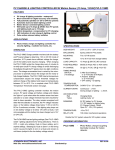
40 AMP, 12/24V IN-LINE PV CHARGE & LIGHTING CONTROLLER
PVLC-40
FEATURES
v
v
v
v
v
v
v
v
v
v
v
PV charge & lighting controller - waterproof
Micro-controller for digital accuracy and reliability
Fully automatic operation on 12V or 24V DC systems
Automatic dusk and dawn lighting control
All night, or adjustable time-off for area lighting with
pre-dawn lighting for signs
Will handle up to 40 Amps @ 28VDC from PV panels
and lighting loads up to 40 Amps
Built-in low voltage disconnect, max load 40 Amps
Built-in temperature compensation for PV charging
LED indication of solar charge & lighting control
Selectable operation for sealed/flooded batteries
Pulse action reduces battery sulfation
APPLICATIONS
v
SPECIFICATIONS
Photo Voltaic charge and lighting controller for:
area lighting and large roadside signs.
OPERATION
The PVLC-40 charge controller monitors both the battery and
PV panel voltage to determine: 12V or 24V DC mode of
operation, if PV panels have sufficient voltage for charge,
and if the battery bank requires charging. When charging
the PVLC-40 cycles the charge relay every 4 minutes to reverify open circuit PV charge voltage to avoid discharging the
batteries through the PV panels when low light conditions
occur. The charge re-connection time is varied by the microprocessor to optimally reduce the charge rate for nearly or
fully charged batteries. The PVLC-40 internal temperature
compensation adjusts the charge threshold voltages for
optimum charge of the battery bank based on temperatures
between 08C to 458C. For a complete chart refer to the
PVCM-10 or PVCM-20 data sheets.
The PVLC-40 lighting controller monitors PV panel voltage
and initiates the “light-on” cycle when a dusk voltage
threshold has been reached and energizes the lighting relay.
It remains energized until either the time selection is
reached, the PV voltage indicates dawn, or the battery
voltage drops below 11.0V (or 22.0V) DC for 5 continuous
minutes. If the lighting relay drops out on low battery voltage
or is below 12V (24V) at dusk, it will not re-energize until the
battery has been charged up to 12V (or 24V) DC. If a “sign”
time range (7,8,9) is selected, the lighting relay will turn on
for the number of hours selected after dark and turn on again
two hours before dawn the next morning. The PVLC-40
must operate through one full 24 hour day/night cycle after
power up before the lighting relay will turn on 2 hours before
dawn. Selecting (6) “all night” on the timing switch causes
the lights to remain on dusk to dawn (subject to the low
battery voltage cutout).
If the timing switch selection is “zero” (0) the PVLC-40 will
operate as a PV charge controller with low voltage
disconnect. The lighting relay will immediately turn on and
will turn off when battery voltage falls below 11.0V or 22.0V
DC. The dusk to dawn lighting functions are bypassed in the
Low Voltage Disconnect mode.
SIZE/WEIGHT:
ENCLOSURE:
MOUNTING:
POWER:
LOAD CAPACITY:
CONNECTION:
3.3"W x 5.5"L x 1.65"H
Epoxy potted in PVC plastic
Two 1/2" #8 screws
8 to 30 V DC from storage battery
40 Amps @ 28V DC (NO contact)
1/4" Bolt Connectors
Ring Connector Molex #BCL814PL
1/4" Spade Battery Negative (-)
FLOODED BATTERY On @ 12.7V DC, Off @ 14.2V DC
PV CHARGE:
@ Room temperature 20-258C
SEALED BATTERY
PV CHARGE:
TIMING RANGE
SWITCHES:
(10 Settings)
TEMPERATURE
COMPENSATION: 0.040V/8C for 12V systems
CURRENT DRAW:
(Values same
for 12V & 24V)
LED INDICATION:
Red
Yellow
MINIMUMS:
TEMPERATURE:
Continuous - [ 5.3mA
During charge or lighting 60mA Nominal,
Higher for LVD Mode “0"
Charging Mode
Lighting Cycle ‘on’
9.5V DC battery for PV charge
11V DC battery for lighting relay
PV Charge Current - 80mA
Open PV - 16V (12V system)
-30 to 758C
RELAY LIFE:
100 million mechanical operations
Double the 12V system values for 24V system values
ORDERING INFORMATION
PVLC-40 -
ATKINSON ELECTRONICS, INC.
Web Site: www.atkinsonelectronics.com
*Blue Jumper Clipped*
On @ 12.4V DC, Off @ 13.9V DC
6 After Dusk Settings (2 Hrs to All Night)
3 Sign Settings (2 Hrs Before Dawn)
1 Low Voltage Disconnect Option
See next page for adjustments
Photo-Voltaic charge & Lighting
Controller module. Relay contacts
rated for 40 Amps @ 28V DC.
REV 12/03
Distributed by:
40 AMP, 12/24V IN-LINE PV CHARGE & LIGHTING CONTROLLER
PVLC-40
PVLC-40 TEMPERATURE THRESHOLDS
PVLC-40 SWITCH - LIGHTING ADJUSTMENTS
Below
08C
On @ 13.3V, Off @ 15.0V
Between
0-58C On @ 13.3V, Off @ 14.8V
Between
5-108C On @ 13.1V, Off @ 14.6V
Between
10-158C On @ 12.9V, Off @ 14.4V
Between
15-308C On @ 12.7V, Off @ 14.2V
Between
30-358C On @ 12.7V, Off @ 14.0V
Between
35-408C On @ 12.6V, Off @ 13.8V
Between
40-458C On @ 12.6V, Off @ 13.6V
Above
458C
On @ 12.7V, Off @ 14.2V
*Gel Cell Batteries - 0.3V Lower
Pos.
Pos.
Pos.
Pos.
Pos.
Pos.
Pos.
Pos.
Pos.
Pos.
“0"
“1"
“2"
“3"
“4"
“5"
“6"
“7"
“8"
“9"
-
Low Voltage Disconnect
On for 2 hrs after dusk
On for 3 hrs after dusk
On for 4 hrs after dusk
On for 6 hrs after dusk
On for 8 hrs after dusk
On from dusk to dawn
On for 6 hrs after dusk, 2 hrs before dawn
On for 4 hrs after dusk, 2 hrs before dawn
On for 2 hrs after dusk, 2 hrs before dawn
INSTALLATION AND STARTUP INSTRUCTIONS
1.
2.
3.
4.
5.
6.
7.
Connect the PV panel and lighting load negative wires to the negative battery post. Connect the PVLC-40 B(+) terminal to
the Battery positive post (user supplied wire and 50 Amp fuse) and the PV panel + wire to the PVLC-40 PV terminal. Wait
to connect the PVLC-40 B(-) terminal to battery negative post.
Adjust the desired time range on the switch per PVLC-15 switch lighting options.
Now connect the PVLC-40 B(-) to the battery negative post to power up the PVLC-40. Verify that the initial battery voltage
is greater than 11V or 22V, and PV voltage is greater than 14V or 28V.
Twelve seconds after power up, the charge relay (red LED) will click the number of times per the switch position with “0"
being 10. If the switch did not get set to the desired position, disconnect the PVLC-40’s B(-) negative wire and reset switch.
Reconnect the PVLC-40's B(-) negative wire and verify the desired timing range. If the open circuit PV voltage is above 16V
(32V) and the battery voltage is below the “turn on” threshold, then the PV charge relay will energize, charging the battery.
Every 4 minutes the PV relay will drop-out momentarily to test for the presence of adequate PV charge sunlight.
To test the lighting function, disconnect the PV wire from terminal, after a short delay( 5-7 seconds) the lighting relay (yellow
LED) should energize the lighting load.
Now disconnect the PVLC-40 B(-) wire and reconnect the PV wire to PV terminal, and then reconnect the black wire.
Mount the PVLC-40 securely with screws and coat the switch with silicone to insure that the entire module is waterproof.
Waterproof the electrical connections with silicone or grease.
Note:
The PVLC-40 is powered by either the battery or PV voltage, which ever is greater. The charge relay is only powered
from the PV voltage. If there is insufficient PV voltage when powering up the PVLC-40, the charge relay will only click
once after a 12 second delay. If there is sufficient PV voltage( >16V/32V), then after a 12 second delay the PV relay
will click out the switch position with “0" being 10 clicks, it then checks the Battery voltage, if its below the “turn on”
threshold, the charge relay energizes after a delay of 5 seconds. If battery voltage is above the turn on threshold, then
it will wait until it drops below the threshold. If the switch setting is in the zero (0) position, both relays will energize.
WIRING DIAGRAM - LIGHTING CONTROL APPLICATION
The PVLC-40 charges the battery from the solar PV panel during the day. At dusk the PVLC-40 senses the low PV panel voltage
and turns on the light for the selected time period. The light will automatically turn off at dawn. In the Sign option, the PVLC-40
also turns on the light two hours before dawn.
ATKINSON ELECTRONICS, INC.
Web Site: www.atkinsonelectronics.com
REV 12/03
Distributed by:
40 AMP, 12/24V IN-LINE PV CHARGE & LIGHTING CONTROLLER
PVLC-40
TROUBLESHOOTING TIPS
Problem
Solution
-
Module doesn’t click on and there is sunlight on the PV panels.
Verify that the battery voltage is less than 12.75V (or 25.5V on a 24V DC system) and that the open PV voltage
is greater than 16V or (32V). If both conditions are met, wait for a 4 minute delay period.
Problem
Solution
-
Module clicks every several minutes.
This is the normal operating sequence.
Problem
Solution
-
Module charges for a few seconds then shuts off for 4 minutes.
The Batteries are fully charged and the charge current was at maximum output.
It may also mean that the Batteries have a poor connection or a bad cell with high internal resistance.
Problem
Solution
-
Module switches on for 1 or 2 minutes and then is off for a much longer period of time.
This is also normal if the battery is at or nearly fully charged and the PV charge current is at or near maximum.
Problem
-
Solution
-
The battery load has been left on and the storage battery has discharged below 8V DC. The PV system is not
charging when the load is turned off.
The PVLC-40 needs at least 9.5V DC from the battery to operate properly. Place the panel in direct sunlight
and jumper the battery and PV terminals for a few minutes, thus bypassing the charge controller allowing the
battery voltage to rise to at least 9.5V DC. Disconnecting the jumper will allow the PVLC-40 to charge the
battery up to normal levels.
Problem
Solution
-
The module is set for lighting control and at dusk fails to turn on lights.
The PVLC-40 checks the battery voltage at dusk to see if batteries are greater than 12V (or 24V) DC, sufficient
to run lights. If not, lock out lighting relay until the solar panels have charged battery above 12V DC (24V DC).
LOW VOLTAGE DISCONNECT APPLICATION
When using the PVLC-40 in a low voltage disconnect application rather than lighting control, set the switch to the “zero” (0)
position. Such applications include solar powered instrumentation or a telecommunications site where sensitive electronic
equipment could be damaged by low battery voltage. The startup instructions may be followed, the only difference is the load
relay will turn on and stay on except for a low battery voltage condition. The presence of PV voltage has no effect on the LVD
operation. A sister product, PVLVD-15, provides more flexibility in low voltage disconnect solar PV applications.
ATKINSON ELECTRONICS, INC.
Web Site: www.atkinsonelectronics.com
REV 12/03
Distributed by: