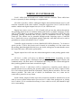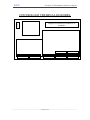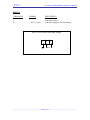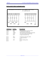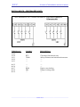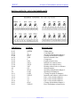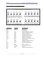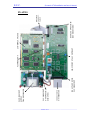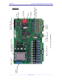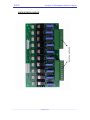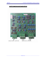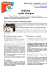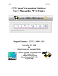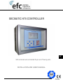
1
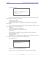
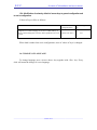
SECMATIC-970 CONTROLLER EN Self-contained and centralized Dryers and Thawing units. INSTALLATION AND USER'S MANUAL MI 970 0700 Cod. 0814819 E.F.C. Secmatic-970 Installation and User's Manual. GENERAL TABLE OF CONTENTS 1st. Part: Recommendations on wiring 2nd. Part: Control 3rd. Part: Miscellaneous _____________________________________________________________________________________ 2 out of 71 E.F.C. Secmatic-970 Installation and User's Manual. 1st. PART RECOMMENDATIONS ON WIRING _____________________________________________________________________________________ 3 out of 71 E.F.C. Secmatic-970 Installation and User's Manual. SECMATIC – 970 GENERAL RECOMMENDATIONS ON WIRING Wiring is to be classified in three different levels. Level 1: Low level analogical and digital signals. - Analogical inputs: ambient probes, Analogical outputs: 0-10 volt. Digital inputs: thermal relay safeties, pressure switches, Computer network communications. Level 2: Alternating current supply and operation. - Digital outputs: command of contactors, solenoids, servomotors, relays ... Controller supply. Level 3: Large power motor and equipment supply. Cables of the same level can be assembled in trunkings or conduits, except for controller supply that is to be laid separately in another conduit. Controller supply will be as much straight as possible from general supply, from a star distribution by means of either a separate hose per machine (parallel supply of several machines is to be avoided) or from three terminals specially prepared for that purpose in electric panel of each dryer. Minimum gap between trunkings will be 20 cm. If this is not possible, cables should be laid in a common trunking with three compartments which have to be separated by means of a grounded metal barrier. Conduits enclosing level 1 cables must not be laid parallel to conduits with level 3 cables at a distance smaller than 1.5 m. If cables of different levels have to intersect, keep them at 90-degrees angles. When these recommendations are difficult to be met, parallel runs must not be longer than 1.5 m. All level 1 cables (low level) should be shielded. _____________________________________________________________________________________ 4 out of 71 E.F.C. Secmatic-970 Installation and User's Manual. WIRING IN CONTROLLER Level 1 cables (low level) and level 2 cables reach the controller. These cables have to arrive separately in three trunkings or compartments. All cables of probes, safeties, analogical outputs and communications (level 1) will reach the controller in the same conduit. Controller supply hose (level 2) will be laid in another conduit and digital outputs hose (level 2) in a different one. Supply hose (three wires: L1, L2/N, Ground) will get into the cabinet through the first packing gland on the left. Within cabinet and fixed to available fastenings on side wall, it will be taken up to supply connector. Ground wire of this hose will be the only grounding entering controller and its only point of attachment will be the supply connector. The cabinet can be grounded through anchor fastening screws. Controller box is fitted with a screw with ground symbol (right side wall) that will not be used to ground but to connect all shields of level 1 cables. Controller supply must have a ferrite, B64290-K82-X830 (Siemens), 7 to 8 turns or spirals (on the 3 wires); this ferrite can be located in its trunking or in the corner near the packing gland through which the hose gets inside, taking into account that the nearer the control the more efficient the performance. Digital outputs hose will enter the cabinet through the second packing gland on the left. All level 1 cables will arrive in different shielded hoses depending on their provenance: ambient probes, distribution box probes, safeties, analogical outputs and communications. All these hoses will distribute their entry into the cabinet through the three packing glands located more towards the right. Shields of level 1 cable hoses will be connected to controller metal cabinet at ground terminal (screw showing the ground symbol on right side wall). Length of cable to be left without shield should be minimized. Shield junction should be the best and shortest possible. The other end of shield (in distribution box, etc.) must not be connected to ground or to any frame. Inside cabinet, length of cables up to their connectors should be minimized to avoid cable in excess within cabinet and to prevent level 1 cables from getting near or joining level 2 cables. If it is considered necessary to leave cable in excess, this should be kept in its own trunking. _____________________________________________________________________________________ 5 out of 71 E.F.C. Secmatic-970 Installation and User's Manual. WIRING BETWEEN CONTROLLER AND DISTRIBUTION BOX, ELECTRIC PANEL AND AMBIENT PROBE BOX All the aforementioned recommendations have to be taken into account too when making this wiring, always avoiding joining or mixing cables of different level or controller supply. Two separate hoses leave ambient humidity and temperature probe box: one of them shielded, with ambient humidity and temperature probes, towards controller, the other with two wires of maximum and minimum safety thermostats to electric panel. Path in common of these two hoses should be minimized and, if possible, these hoses should be kept separated from probe box itself. Shields of hoses leaving distribution box towards controller have to be insulated in this end as they are grounded in controller. _____________________________________________________________________________________ 6 out of 71 _____________________________________________________________________________________ 7 out of 71 CANALETA 1 (NIVEL 2) SEPARAR LOMUCH MAS POSIBLE TO BE KEPT APART AS AS POSSIBLE BORNAS 72 ...... 77 y 84.....89 BORNAS 24 ...... 28 BORNAS 4 ...... 23 y 41.....60 CADA MANGUERA SOLO LLEVARA UN SOLO TIPO DE SEÑAL COMUNICACIONES (manguera apantallada) SALIDAS DIGITALES (manguera) BORNAS 61.....65 SALIDAS ANALOGICAS (manguera apantallada) BORNAS 66 ...... 71 y 78.....83 ENTRADAS PT100 (manguera apantallada) ENTRADAS 0/10 VOLTIOS Y 4/20 mA. (manguera apantallada) BORNAS 0. 1. 2 BORNAS 29 ...... 40 ENTRADAS DIGITALES (manguera apantallada) TERMINAL OF CABINET WHERE BORNE DEL ARMARIO AL SHIELDS. QUE SE DEBEN TO CONNECT HOSE DE CONECTAR LAS PANTALLAS DE LAS THE OTHER END OF SHIELD MANGUERAS. EL OTRONOT EXTREMO DE LA PANTALLATO NO SE MUST BE CONNECTED CONECTARA A NINGUN PUNTO. ANY POINT. IMPORTANT. IMPORTANTE NOT TO MIX CABLES IN TRUNKING 3 NO MEZCLAR CABLES DE LA CANALETA 3 (NIVEL 1) (LEVEL 1) WITH CABLES OF OTHER CON CABLES DE OTRAS CANALETAS (NIVEL 2) TRUNKINGS (LEVEL 2). ALIMENTACION 220V (manguera) CANALETA 2 (NIVEL 2) EL CABLE DE ALIMENTACION SUJETARLO CON BRIDAS EN LA SUJECCIONES DISPONIBLES EN LA PARED LATERAL DEL ARMARIO NO CABLE IN EXCESS TO BE LEFT IN EN NO LENGTH DEJAR NADA DE CABLE SOBRANTE ELTHE INTERIOR DEL ARMARIO. CABINET. SHORTEST ONE TO BE IN ITS TRUNKING. DEJAR LO MINIMO EN SU RESPECTIVA CANALETA CANALETA 3 (NIVEL 1) E.F.C. Secmatic-970 Installation and User's Manual. E.F.C. Secmatic-970 Installation and User's Manual. WIRING IN DRYER (DISTRIBUTION BOX) Use the distribution box only for low level signals (level 1). Therefore, the twowire hose of maximum and minimum safety thermostats must not be taken to this box but directly to electric panel. If this hose is to share a trunking with ambient humidity and temperature probes, it would be advisable to add a ferrite in these two wires just outside the electric panel, to avoid any interferences of this line being induced on probe cables (Siemens B64290-K82-X830 ferrite with at least 7 or 8 turns or spirals). Shields of hoses coming from probes of compressor discharge and suction temperature, of suction and discharge pressure switches and of contacts of micro relays should be attached at unit frame directly at distribution box inlet with the best and shortest possible junction. Under no circumstances can the other end of shield be in contact with frame or ground. There must not be a connection with a ground cable between the electric panel and distribution box. This connection already exists through frame. . WIRING IN DRYER (ELECTRIC PANEL) Install RC filters in all coils of contactors, relays and micro relays. These filters are to be those recommended by manufacturer of each actuator. Otherwise, a filter with the following characteristics is to be used: RC : Condenser 220nF X type. Winded resistance, 3W, 47 to 220 ohm. Other type of resistance could be pierced and this would eliminate filter efficiency. Filters must be installed in micro relays also, although usually they are not in operation, nevertheless, all of them make a connection at the same time whenever there is a voltage start. _____________________________________________________________________________________ 8 out of 71 E.F.C. Secmatic-970 Installation and User's Manual. WIRING IN DRYER (MACHINES) Cables of probes (like those of compressor suction and discharge temperature, etc.) must be prevented from joining or fastening to level 2 cables (like valve operations, etc.). They must be kept apart as much as possible. All valves have to be fitted with RC filters. WIRING FOR COMMUNICATIONS BETWEEN SEC-970 AND COMPUTER. Communication cable between controller and computer must be a four-wire shielded cable, two wires for transmission and two for reception, and interlaced in twos, separate shields for each couple and one shield common for both couples. This communication cable transmits an RS-422 signal that by means of a converter becomes an RS-232 signal to enter computer. Converter recommended by E.F.C. is WESTERMO MA-45. _____________________________________________________________________________________ 9 out of 71 E.F.C. Secmatic-970 Installation and User's Manual. 2nd. Part CONTROL _____________________________________________________________________________________ 10 out of 71 E.F.C. Secmatic-970 Installation and User's Manual. TABLE OF CONTENTS 1. DESCRIPTION...................................................................................... 13 2. GETTING IN CONTACT WITH YOUR SECMATIC-970................. 14 2.1 LIQUID CRYSTAL DISPLAY (LCD) .......................................................................... 15 2.2 CONTROL KEYBOARD ............................................................................................ 16 2.3. SIGNAL LAMPS AND ON/OFF. KEY ....................................................................... 17 3. MAIN DISPLAY ................................................................................... 18 4. MAIN MENU ........................................................................................ 21 5. AUTOMATIC CONTROL .................................................................... 23 5.1.START-UP OF DRYER CONTROLLED BY HUMIDITY. ................................................. 23 5.1.1 Access to main menu ..................................................................................... 23 5.1.2. Selection of automatic running..................................................................... 24 5.1.3. Selection of control type by humidity ........................................................... 25 5.1.4. Selection and change of setpoints................................................................. 26 5.1.5. Control start-up ............................................................................................ 27 5.2. START-UP OF DRYER CONTROLLED BY HUMIDITY_GV......................................... 27 5.3. START-UP OF DRYER CONTROLLED BY TIME ......................................................... 28 5.4. START-UP OF DRYER CONTROLLED BY HUMIDITY AND TIME. ................................ 28 5.5. START-UP OF DRYER AS A WET CURING ROOM ...................................................... 28 5.6. START-UP OF DRYER AS A STORAGE ROOM ........................................................... 29 5.7. START-UP OF THAWING UNIT CONTROLLED BY STANDARD THAWING ................... 29 5.8. START-UP OF THAWING UNIT CONTROLLED BY PROBE THAWING. ......................... 29 6. PROGRAMMED CONTROL .............................................................. 30 6.1 SELECTION OF PROGRAMME NUMBER. ................................................................... 30 6.2 SELECTION OF STEP NUMBER AND ITS LENGTH....................................................... 30 6.3 APPLICATION OF PROGRAMMED CONTROL TO THAWING UNIT ................................ 31 7. INPUTS AND OUTPUTS STATUS ..................................................... 31 7.1 SELF-CONTAINED UNITS......................................................................................... 32 7.2 CENTRALIZED UNITS .............................................................................................. 34 8. GRAPHS ................................................................................................ 36 9.- FAILURES ........................................................................................... 37 9.1. FAILURES AND CODES ........................................................................................... 38 10. DEFROST ENABLING / DISABLING.............................................. 39 11. PERMIT / PROHIBIT OUTSIDE AIR ............................................... 40 12. PERMIT / PROHIBIT RENEWALS.................................................. 41 12.1. PERMIT CYCLIC RENEWAL................................................................................... 41 12.2. FORCED RENEWAL. ............................................................................................. 42 12.3. PERMIT LIMITED RENEWAL. ................................................................................ 42 _____________________________________________________________________________________ 11 out of 71 E.F.C. Secmatic-970 Installation and User's Manual. 13. DISPLAY OF LOSSES ...................................................................... 44 14. AIR DISTRIBUTION DAMPERS ..................................................... 45 15. TEMPERATURE ALARM AND ACCESS PERMIT TO MODIFICATIONS ............................................................................47 15.1 - TEMPERATURE ALARM AND ACCESS PERMIT TO MODIFICATIONS BY USER.. ...... 47 15.2 - ENERGY SAVING (OFF-PEAK HOURS). ................................................................ 48 15.3 - LOADING CONFIGURATION BY DEFAULT OR RESETTING HISTORY FROM 'USER'S CONFIGURATION' DISPLAY .................................................................................... 50 15.4 - MODIFICATION OF VALUES BY DEFAULT OF ACCESS KEYS TO GENERAL CONFIGURATION AND TO USER'S CONFIGURATION. ...................................................... 52 16. CHANGE OF LANGUAGE................................................................ 52 _____________________________________________________________________________________ 12 out of 71 E.F.C. Secmatic-970 Installation and user's Manual 1. DESCRIPTION The SECMATIC-970 controller is a microprocessor-based equipment consisting of several modules, specially designed to manage drying rooms or thawing rooms. It allows either the indefinite automatic operation or a programmed operation with the possibility of setting and storing ten programmes of more than 15 phases each. It is fitted with many types of control, among which the most important are: - Drying control: (not available in thawing units): - By Humidity. - By Humidity_GV. - By Time. - By Humidity and Time. - Wet curing control: (not available in thawing units) - Storage room control. - Outside air utilization (not available in thawing units) - Air renewals (not available in thawing units ) Thawing control: (not available in dryers) - Standard - By probes All drying controls are fitted with a temperature control during process. A liquid crystal display (LCD) allows the following values of dryer, among others, to be seen: - Ambient values. - Setpoint values. - Type of control and of mode (automatic or programmed). - Signalling of activations. - Failures and alarms, including history. - Graphs of last two hours. _____________________________________________________________________________________ 13 out of 71 E.F.C. Secmatic-970 Installation and user's Manual 2. GETTING IN CONTACT WITH YOUR SECMATIC-970 Control panel of SECMATIC-970 controller is divided into three main sections: - Liquid crystal display (LCD). - Control keyboard. - Signal lamps including the run / stop lit pushbutton. _____________________________________________________________________________________ 14 out of 71 E.F.C. Secmatic-970 Installation and user's Manual 2.1 Liquid crystal display (LCD) It allows the display and control of parameters, setpoints and message from unit and dryer. Main display _____________________________________________________________________________________ 15 out of 71 E.F.C. Secmatic-970 Installation and user's Manual 2.2 Control keyboard Up Arrow × : It allows moving upwards in menus to select the different options. It allows increasing numerical values of setpoints. Down arrow Ø : It allows moving downwards in menus to select the different options It allows decreasing numerical values of setpoints. Right arrow Ö : Once the setpoint to be modified has been selected, it allows moving to numerical field to modify it. Left arrow Õ : It allows returning from numerical field of modified setpoint. <E> key : It allows validating or entering one of the options in menus. It allows validating value of a modified setpoint. <F> key: It allows access to main menu from main display. <Esc> key: It allows getting out (Escape) from any point to main display. _____________________________________________________________________________________ 16 out of 71 E.F.C. Secmatic-970 Installation and user's Manual 2.3. Signal lamps and key ON/OFF. VENTILATION REFRIGERATION HEATING DEFROST FAILURE ON / OFF (PAUSE) Ventilation: It shows that fan is in operation. Refrigeration: It shows that unit is under refrigeration process to recover set temperature. Heating: It shows that unit is under heating process to recover set temperature. Defrost: It shows that unit is defrosting. Failure: It shows that there is a failure in unit or dryer. ON / OFF (Pause) : Connection / disconnection of all digital outputs. _____________________________________________________________________________________ 17 out of 71 E.F.C. Secmatic-970 Installation and user's Manual 3. MAIN DISPLAY Essential information for unit control is contained in main display. To have access to main display it is enough to press <Esc> key from any menu of controller. Display is divided into five areas: 1. Control type Type of control that rules dryer is displayed here. 2. Humidity control Ambient humidity and drying setpoints are displayed here. 3. Temperature control. Ambient temperature and its setpoint are displayed here. 4. Failures and alarms. There are two types of indications during normal operation: _____________________________________________________________________________________ 18 out of 71 E.F.C. Secmatic-970 Installation and user's Manual a.- If control is automatic, it indicates time elapsed since process start-up. b.- If control is programmed, it shows: - Number of current programme. - Number of current phase. - Time elapsed in current phase. - Remainder time for the new phase to start. If there is a failure in operation, it is shown in this area of display. Failure alarm will not disappear until any key of control keyboard is pressed. 5. Signalling VENTILATION REFRIGERATION HEATING DEFROST FAILURE DRYING (not available in thawing units) AIR RENEWAL HUMIDIFICATION Ventilation: It means that fan is in operation. Refrigeration: It means that unit is under refrigeration process to recover set temperature. Heating: It means that unit is under heating process to recover set temperature. Drying: It means that unit is in the drying cycle. (not available in thawing units) Humidification: It means that unit is in humidification cycle. Defrost: It means that unit is defrosting. Unfreezing: It means that unit is in unfreezing cycle. (Not available in dryers) Failure: It means that there is a failure in unit or dryer. _____________________________________________________________________________________ 19 out of 71 E.F.C. Secmatic-970 Installation and user's Manual Outside air / renewal: If this signal is enabled together with drying signal, it means that drying cycle is being carried out with outside air. Otherwise, it means that air in room is being renewed. (Outside air is not available in thawing units) REMARK: Upon placing controller under voltage, the display shown below appears, where we can see ambient temperature and humidity, reference of controller and a message requiring us to press <F> key to have access to main menu This display will also appear when there is no control started in controller. . _____________________________________________________________________________________ 20 out of 71 E.F.C. Secmatic-970 Installation and user's Manual 4. MAIN MENU MAIN MENU Automatic control Programmed control Inputs / Outputs status Graphs Failures *Energy saving Activate Defrost cycle *Permit outside air Permit cyclic renewal Activate forced renewal Permit limited renewal *Display of losses (1) (2) (2) (2) *) Not available in thawing units Main menu allows access to unit different controls. To have access to main menu, press <F> key from main display. We can see that AUTOMATIC CONTROL appears automatically selected in reverse video. With <Up arrow> and <Down arrow> we can move on menu to select the desired option, afterwards we will press <E> key that will allow us to validate the option chosen. 1. Automatic control. From this option there is access to changes of control type and setpoints. 2. Programmed control It allows the design and execution of programmes that permit changes of setpoints in time. 3. Inputs/outputs status It allows us to know whether the different controller inputs or outputs are enabled (solenoids, contactors, ...) 4. Graphs It makes possible to see a graph of ambient humidity and temperature for the last two running hours. _____________________________________________________________________________________ 21 out of 71 E.F.C. Secmatic-970 Installation and user's Manual 5. Failures It contains a history of failures showing moments, referred to an hour counter, when the different anomalies occurred and where repaired. 6. Energy saving. (Not available in thawing units) 7. Activate / deactivate defrost cycle It allows: - activating manual defrost - deactivating a defrost cycle in operation. 8. Permit / prohibit outside air (only if validated) (Not available in thawing units) Drying by means of outside air used to reduce energy consumption is either permitted or prohibited. 9. Permit / prohibit cyclic renewal (only if validated) Operation of cyclic renewals during processes is either permitted or prohibited . 10. Permit / prohibit forced renewal (only if validated) The immediate air renewal is either permitted or prohibited 11. Permit / prohibit limited renewal (only if validated) Limitation in air renewals depending on temperature difference between outside air and temperature set in dryer is either permitted or prohibited _____________________________________________________________________________________ 22 out of 71 E.F.C. Secmatic-970 Installation and user's Manual 5. AUTOMATIC CONTROL The automatic control of dryer can be carried out in different ways: - Drying control: - By Humidity. - By Humidity_GV. - By Time - By Humidity and time. - Control of wet curing. - Control of storage room. The automatic control of thawing unit can be carried out in different ways: - Control of standard thawing - Control of thawing by probes - Control of storage room As this is the most commonly used control we will explain in depth drying controlled by humidity. Starting up of dryer with remaining types of controls is carried out in a similar way. 5.1. Start-up of dryer controlled by humidity. 5.1.1 Access to main menu If there is any control started, main display is to be accessed firstly by pressing <Esc> key. If no control is started or when controller is being put under voltage, the following display appears where we can see ambient temperature and humidity, controller reference and a message requesting us to press <F> key to have access to main menu. When pressing <F> key we have access to main menu. _____________________________________________________________________________________ 23 out of 71 E.F.C. Secmatic-970 Installation and user's Manual MAIN MENU Automatic control. Programmed control Inputs / outputs status Graphs Failures Energy saving Activate defrost cycle Permit outside air Permit cyclic renewal Activate forced renewal Permit limited renewal Display of losses (1) (2) (2) (2) 5.1.2. Selection of automatic operation We can see that AUTOMATIC CONTROL appears automatically selected in reverse video. With up arrow and down arrow we can move on menu and select an option. Then, we press <E> key what will allow us to validate the option chosen. In main menu we select the option AUTOMATIC CONTROL and validate it by pressing the <E> key. A display similar to the following will appear: AUTOMATIC CONTROL Control type . Humidity Temperature setpoint CTEM 3.0º High humidity limit HR2 85.2% Low temperature limit HR1 80.0% Cyclic time Start-up control The sentence CONTROL TYPE will appear selected. _____________________________________________________________________________________ 24 out of 71 E.F.C. Secmatic-970 Installation and user's Manual With <Right arrow> key we can move to field which will allow us to select control type as required. AUTOMATIC CONTROL Control type. Humidity Temperature setpoint CTEM 3.0º High humidity limit HR2 85.2% Low humidity limit HR1 80.0% Cyclic time Start-up control 5.1.3. Selection of control type by humidity With <Up arrow> and <Down arrow> keys control type with which we want dryer to be managed is selected. These control types are as follows: - Drying control: - By humidity. - By humidity_GV. - By time. - By Humidity and time. - Wet curing control. (only if validated) - Storage room control. We choose control by humidity and we press <E> key. Setpoints necessary for operation will appear automatically. Finally, we press <Left arrow> key to go back to text fields. _____________________________________________________________________________________ 25 out of 71 E.F.C. Secmatic-970 Installation and user's Manual 5.1.4. Selection and change of setpoints Having selected control by humidity we have to enter the following setpoints: - CTEMP Temperature - HR2 High humidity limit. - HR1 Low humidity limit. - VVE Fan speed.(1 or 2) (Not available) - TVM Fan running cyclic time. - TVP Fan stop cyclic time. - TRM Air renewal running cyclic time. - TRP Air renewal stop cyclic time. Air renewals are possible only if there are the necessary dampers and in addition they are permitted from main menu. The way to enter the different setpoints is similar to the one described to enter control type. In numerical fields, if <Up arrow> or <Down arrow> key is kept held down, increase or decrease of digits will be quicker. To have access to cyclic time menu, firstly we have to select the option CYCLIC TIMES and then validate it with <E> key. AUTOMATIC CONTROL Control type. Humidity Temperature setpoint CTEM 3.0º High humidity limit HR2 85.2% Low humidity limit HR1 80.0% Cyclic time Start-up control From cyclic time menu it is possible to return to previous menu by selecting the option SETPOINTS. Cyclic time *Fan speed Fan running time Fan stop time Renewal running time Renewal stop time Setpoints VVE TVM TVP TRM TRP 1 1'00’’ 10'00’’ 5'00’’ 24H'00’ Start-up control * (Not available) _____________________________________________________________________________________ 26 out of 71 E.F.C. Secmatic-970 Installation and user's Manual 5.1.5. Control start-up Dryer start-up will be carried out by selecting and validating the option CONTROL START-UP and then pressing <ON /OFF> key located next to signal lamps. Once unit has been started-up we press <Esc> key to return to main display. AUTOMATIC CONTROL Control type. Humidity Temperature setpoint CTEM 3.0º High humidity limit HR2 85.2% Low humidity limit HR1 80.0% Cyclic time Start-up control 5.2. Start-up of dryer controlled by humidity_GV- The difference between this control and the previous one is just that if humidity decreases 4 points with respect to low humidity setpoint, the humidification and ventilations outputs are enabled until humidity has reached the low humidity setpoint plus 1 point. If HRroom <= HRmin – 4% until HRroom > HRmin + 1% V and GV are enabled For that purpose, the following steps are to be taken: 1. Main menu is to be accessed. 2. Select and validate the automatic control. 3. Select and validate control type by Humidity_GV. 4. Enter setpoints necessary for operation - CTEMP Temperature - HR2 High humidity limit. - HR1 Low humidity limit. - VVE Fan speed.(1 or 2, if it is a two-speed motor) (Not available) - TVM Fan running cyclic time. - TVP Fan stop cyclic time. - TRM Air renewal running cyclic time. - TRP Air renewal stop cyclic time. 5. Start-up control. _____________________________________________________________________________________ 27 out of 71 E.F.C. Secmatic-970 Installation and user's Manual 5.3. Start-up of dryer controlled by time 1. Main menu is to be accessed 2. Select and validate the automatic control. 3. Select and validate control type by time. 4. Enter setpoints necessary for operation - CTEMP Temperature - TSM Drying running time. - TSP Drying stop time. - VVE Fan speed. (Not available) - TVM Fan running cyclic time. - TVP Fan stop cyclic time. - TRM Air renewal running cyclic time. - TRP Air renewal stop cyclic time. 5. Start-up control. 5.4. Start-up of dryer controlled by humidity and time 1. Main menu is to be accessed 2. Select and validate the automatic control. 3. Select and validate control type by humidity and time. 4. Enter setpoints necessary for operation - CTEMP Temperature - HR2 High humidity limit. - HR1 Low humidity limit. - TSM Drying running time. - TSP Drying stop time. - VVE Fan speed. (Not available) - TVM Fan running cyclic time. - TVP Fan stop cyclic time. - TRM Air renewal running cyclic time. - TRP Air renewal stop cyclic time. 5. Start-up control. 5.5. Start-up of dryer as a wet curing room. 1. Main menu is to be accessed 2. Select and validate the automatic control. 3. Select and validate control type as a curing room. 4. Enter setpoints necessary for operation - CTEMP Temperature - HR2 High humidity limit. - HR1 Low humidity limit. - VVE Fan speed. (Not available) - TVM Fan running cyclic time. - TVP Fan stop cyclic time. - TRM Air renewal running cyclic time. - TRP Air renewal stop cyclic time. 5. Start-up control. _____________________________________________________________________________________ 28 out of 71 E.F.C. Secmatic-970 Installation and user's Manual 5.6. Start-up of dryer as a storage room 1. Main menu is to be accessed 2. Select and validate the automatic control. 3. Select and validate control type as a storage room. 4. Enter setpoints necessary for operation - CTEMP Temperature - VVE Fan speed. (Not available) - TVM Fan running cyclic time. - TVP Fan stop cyclic time. 5. Start-up control. 5.7. Start-up of dryer controlled by standard thawing. 1.- Main menu is to be accessed 2.- Select and validate the automatic control. 3.- Select and validate control type by standard thawing. 4.- Enter setpoints necessary for operation - CTEMP Temperature - HR2 High humidity limit (if humidifier is available) - HR1 Low humidity limit. (if humidifier is available) - TVM Fan running cyclic time. - TVP Fan stop cyclic time. 5.- Start-up control. 5.8. Start-up of dryer controlled by probe thawing 1.- Main menu is to be accessed 2.- Select and validate the automatic control. 3.- Select and validate control type by humidity and time. 4.- Enter setpoints necessary for operation - CTEMP Temperature - HR2 High humidity limit (if humidifier is available) - HR1 Low humidity limit. (if humidifier is available) - CTSP Product surface temperature. - CTIP Product internal temperature. - TVM Fan running cyclic time. - TVP Fan stop cyclic time. 5.- Start-up control. _____________________________________________________________________________________ 29 out of 71 E.F.C. Secmatic-970 Installation and user's Manual 6. PROGRAMMED CONTROL 6.1 Selection of programme number From main menu we select the option PROGRAMMED CONTROL and validate it by pressing <E> key. Automatic control Programmed control Inputs/outputs status Graphs Failures Activate defrost cycle Permit outside air Permit cyclic renewal Activate forced renewal Permit limited renewal Then, we select number of programme we want to create, modify or edit by means of <Up arrow> or <Down arrow> keys . Then, we validate with <E> key. PROGRAMME = 01 6.2 Selection of number of step and its length. PROGRAMME = 1 STEP =O1 Control type Humidity Temperature setpoint CTEM High humidity limit HR2 Low humidity limit HRl Cyclic time LENGTH= 00h00’ 13.2 º 80.0 % 76.0 % Start-up control We select step to be modified and then its length by always pressing <E> key after any modification. A length of time equal to zero will mean that this step is the last one of programme and that dryer will remain running indefinitely with the setpoints of the said step. _____________________________________________________________________________________ 30 out of 71 E.F.C. Secmatic-970 Installation and user's Manual It is possible to create 9 programmes of 25 steps each. Once number of programme, number of step and length have been chosen, we move onto PROGRAMME and by means of <Down arrow> key we go over setpoints we want to modify. Modification of setpoints is similar to the one in AUTOMATIC CONTROL. PROGRAMME = 1 Control type STEP =O1 Humidity LENGTH= 00h00’ PROGRAMME = 1 Control type STEP =O1 Humidity LENGTH= 00h00’ PROGRAMME = 1 STEP =O1 Control type Humidity LENGTH= 00h00’ 6.3 Application of programmed control in Thawing unit. The best way to carry out a controlled thawing process is to use the "Thawing control by probes" and to create a programme with the steps considered necessary depending on type of product, load, speed, etc. (see 5.8) A standard thawing process is described below (values mentioned are a reference and user must modify them depending on his requirements): - CTEMP - CTSP - CTIP 16ºC (this value should decrease in successive steps as thawing progresses) 4ºC (this value can be kept in all steps) 1ºC (this value can be kept in all steps) And a last step (time=0= indefinite), of "Storage control" (see chapter 5.6), to store unfrozen products at, for example, 3ºC. Times to be set to carry out thawing should be adjusted depending on mass, product and several other factors, (it is usual to operate in thawing processes with times adding up between 24 and 72 hours, depending on the above mentioned factors, but "each person has his own way of thinking" and this point is not binding). This “control of thawing by probes”, has two essential characteristics. The first one is that as soon as CTSP or CTEM are reached machine stops providing heat. The second one is that as soon as CTIP is reached by product internal Temperature, step is considered finished and with no need to wait for step total time to elapse, it will automatically jump to the following step that in last control would be "control of storage". This means that as soon as thawing has finished it goes directly to storage without waiting for timed fixed to elapse. 7. INPUTS AND OUTPUTS STATUS _____________________________________________________________________________________ 31 out of 71 E.F.C. Secmatic-970 Installation and user's Manual 7.1 Self-contained unit From main menu we select the option INPUTS AND OUTPUTS STATUS and we validate it by pressing the <E> key. Automatic control Programmed control Inputs / outputs status Graphs Failures Energy saving Activate defrost cycle Permit outside air Permit cyclic renewal Activate forced renewal Permit limited renewal Display of losses Then, a display where status, enabled or not, of different outputs of controller, is accessed. OUTPUTS STATUS 01 Alarm 02 Fan 03 CP1A 60% 04 CP1C 05 VSD 06 Compressor 07 VSL 08 VSCI 09 VSCE 10 VSC Analogical inlets <F> Yes/No Yes/No Yes/No Yes/No Yes/No Yes/No Yes/No Yes/No Yes/No Yes/No 11 GV Yes/No 12 CP2A 0% Yes/No 13 CAEI Yes/No 14 CAE2 Yes/No 15 VSE-CI Yes/No 16 Vl Yes/No 17 V2 Yes/No 18 V3 Yes/No 19 CP2C Yes/No 20 VSE-CE Yes/No By pressing <F> key, we reach a display with all values of analogical inputs. ANALOGICAL INPUTS 01 Ambient Temperature 02 Ambient humidity .: 03 Outside Temperature : 04 Outside Humidity : 05 Compressor suction pressure. 06 Compressor discharge pressure 07 Compressor suction temp. 08 Compressor discharge temp. 09 Sample weight 10 Auxiliary inlet Analogical inputs <F> 35.8º 75.7% -4.6º 48.5% 15.4k 14.4k 34.8º 34.6º 9.45 kg 7.5% _____________________________________________________________________________________ 32 out of 71 E.F.C. Secmatic-970 Installation and user's Manual By pressing <F> key again we will have access to display of Product surface temperature and Product internal temperature probes. ANALOGICAL INPUTS 11 Product surface temperature 12 Product internal temperature: 3.8º -2.7% Digital inputs <F> We press <F> key again to have access to status of digital inputs. DIGITAL INPUTS 01 Compressor pressure switch. 02 Failure in Fan thermal relay 03 Room thermostat 04 Air-cooled cond. thermal relay 05 Compressor thermal relay 06 Oil lacking in compressor 07 Compressor klixon Yes/No Yes/No Yes/No Yes/No Yes/No Yes/No Yes/No Analogical outputs <F> Finally, by pressing again <F> key, we can see display of output analogical values. ANALOGICAL OUTPUTS Analogical output 1 Analogical output 2 Analogical output 3 Analogical output 4 52.5% 10.0º 0.0% 100% Return to Main menu <Esc> From any of above displays it is possible to return to main display by pressing <Esc> key. _____________________________________________________________________________________ 33 out of 71 E.F.C. Secmatic-970 Installation and user's Manual 7.2 Centralized unit From main menu we select the option INPUTS AND OUTPUTS STATUS and we validate it by pressing the <E> key. Automatic control Programmed control Inputs / outputs status Graphs Failures Energy saving Activate defrost cycle Permit outside air Permit cyclic renewal Activate forced renewal Permit limited renewal Display of losses Then, a display where status, enabled or not, of different outputs of controller, is accessed. OUTPUTS STATUS 01 Alarm 02 FaN 03 CPB1 04 CPB2 05 VSD 06 SGF1 07 SGF2 08 SGC1 09 SGC2 10 SWC Analogical inputs <F> Yes/No Yes/No Yes/No Yes/No Yes/No Yes/No Yes/No Yes/No Yes/No Yes/No 11 GV 12 SH 13 CAEI 14 CAE2 19 Aux.fan Yes/No Yes/No Yes/No Yes/No Yes/No By pressing <F> key, we reach a display with all values of analogical inputs. ANALOGICAL INPUTS 01 Ambient temperature 02 Ambient humidity 03 Outside temperature 04 Outside humidity 07 Cooling battery inlet temp. 08 Cooling battery outlet temp. 09 Sample weight 10 Auxiliary inlet Analogical inputs <F> 3.2º 83.5% 15.1º 80.3% -9.3º -6.2º 9.2 kg 0.0% _____________________________________________________________________________________ 34 out of 71 E.F.C. Secmatic-970 Installation and user's Manual By pressing again <F> key we will have access to display of Product surface temperature and Product internal temperature probes. ANALOGICAL INPUTS 11 Product surface temperature 12 Product internal temperature: 3.8º -2.7% Digital inputs <F> We press <F> key again to have access to status of digital inputs. DIGITAL INPUTS 02 Failure of fan thermal relay 03 Room thermostat 08 Engine room locking Yes/No Yes/No Yes/No Analogical outputs <F> Finally, by pressing again <F> key, we can see display of output analogical values. ANALOGICAL OUTPUTS Analogical output 1 Analogical output 2 Analogical output 3 Analogical output 4 52.5% 10.0º 0.0% 100% Return to Main menu <Esc> From any of above displays it is possible to return to main display by pressing <Esc> key _____________________________________________________________________________________ 35 out of 71 E.F.C. Secmatic-970 Installation and user's Manual 8. GRAPHS From main menu we select the option GRAPHS and we validate it by pressing the <E> key. MAIN MENU Automatic control Programmed control Inputs / outputs status Graphs Failures Energy saving Activate defrost cycle Permit outside air Permit cyclic renewal Permit forced renewal Permit limited renewal Display of losses We have access then to display of maximum bands that on large scale shows, in two graphs, ambient humidity and temperature existing in dryer for the last 2 hours. By pressing <F> key, scale of above graphs can be enlarged to the utmost. From this point, we either press <F> key to return to previous display (Maximum bands) or we press <Esc> key to have access to main display. _____________________________________________________________________________________ 36 out of 71 E.F.C. Secmatic-970 Installation and user's Manual 9.- FAILURES From main menu we select the option FAILURES and validate it by pressing the <E> key. MAIN MENU Automatic control Programmed control Inputs / outputs status Graphs Failures Energy saving Activate defrost cycle Permit outside air Permit cyclic renewal Activate forced renewal Permit limited renewal Display of losses Display of failure history is then accessed. FAILURES Machine hours 23782 Al.Ambient temp. 23782 23782 A2.Ambient humidity 11719 12345 A3.Outside temp. 3459 4534 A4.Outside humidity 659 1244 *A5.Comp. suction pressure 319 0 *A6.Comp. discharge press. 123 145 A7.Comp. suction temp. 89 89 A8.Comp. discharge temp. 19 19 A9.Sample weight 19 0 *D1.Compressor pressure switch 17 19 Previous Failures <F> FAILURES Machine hours 23782 D2.Fan thermal relay 12 D3.Room thermostat.: 11 *D4.Aircooled cond.thermal relay 8 *D5.Compressor thermal relay 8 *D6.Oil lacking in compr. 5 *D7.Klixon Compressor : 1 **D8 Engine room locking 8 12 15 0 9 5 2 0 Return to Main menu <Esc> *) Not available in centralized units **) Not available in self-contained units Display contains the last 10 failures occurred. Failures are ordered in reverse chronological order. In right top part there is an hour counter. This is enabled whenever SECMATIC970 controller is under voltage. By pressing <F> key, we can obtain up to four displays with 10 failures each, this means that a history with the last 40 failures occurred is available. Failure and its code are shown, followed by appearance and disappearance moment referred to hour counter of unit operation. _____________________________________________________________________________________ 37 out of 71 E.F.C. Secmatic-970 Installation and user's Manual 9.1. Failures and codes A9 A11 A12 Failure in ambient temperature probe. Failure in ambient temperature humidity. Failure in outside temperature probe. Failure in outside humidity probe. Failure in compressor suction pressure probe. Failure in compressor discharge pressure probe. Failure in compressor suction temperature probe or Failure in cooling battery inlet temperature probe. Failure in compressor discharge temperature probe or Failure in cooling battery outlet temperature. Failure in sample weight probe. Failure in product surface temperature. Failure in product internal temperature. D1* D2 D3 D4* D5* D6* D7* D8** D9 D10 Compressor high and low pressure switch enabled. Fan thermal relay enabled. Room temperature safety thermostats enabled. Air-cooled condenser thermal relay enabled. Compressor thermal relay enabled. Oil pressure switch enabled. Compressor klixon enabled. Engine room locking enabled. Damper closing safety enabled. High temperature failure. Al A2 A3 A4 A5* A6* A7 A8 *) Not available in centralized units. **) Not available in self-contained units _____________________________________________________________________________________ 38 out of 71 E.F.C. Secmatic-970 Installation and user's Manual 10. DEFROST ENABLING / DISABLING Defrost cycle is automatic. However, if, at any time, it is advisable to carry it out at once, we will select the option ENABLE DEFROST CYCLE from main menu and we will validate it by pressing <E> key. MAIN MENU Automatic control Programmed control Inputs / outputs status Graphs Failures Energy saving Enable defrost cycle Permit outside air Permit cyclic renewal Enable forced renewal Permit limited renewal Display of losses Whenever defrosting is being carried out, it is possible to end it by hand from main menu. The option DISABLE DEFROST CYCLE is selected and then it is validated with <E> key. MAIN MENU Automatic control Programmed control Inputs / outputs status Graphs Failures Energy saving Disable Defrost Cycle Permit outside air Permit cyclic renewal Activate forced renewal Permit limited renewal Display of losses _____________________________________________________________________________________ 39 out of 71 E.F.C. Secmatic-970 Installation and user's Manual 11. PERMIT / PROHIBIT OUTSIDE AIR (Not available in thawing units) Only if your controller is fitted with the possibility of drying with outside air. The option of outside air allows saving energy provided there are good conditions when drying cycle takes place with outside air instead of with machine. From main menu, the option PERMIT OUTSIDE AIR is selected and then it is validated by pressing <E> key. MAIN MENU Automatic control Programmed control Inputs / outputs status Graphs Failures Energy saving Activate defrost cycle Permit outside air. Permit cyclic renewal Activate forced renewal Permit limited renewal Display of losses If, after the option of operation with outside air has been selected, we wish to cancel it to carry out drying with machine, we have to select, from main menu, the option PROHIBIT OUTSIDE AIR and validate it by pressing <E> key. MAIN MENU Automatic control Programmed control Inputs / outputs status Graphs Failures Energy saving Activate defrost cycle Prohibit outside air. Permit cyclic renewal Activate forced renewal Permit limited renewal Display of losses _____________________________________________________________________________________ 40 out of 71 E.F.C. Secmatic-970 Installation and user's Manual 12. PERMIT / PROHIBIT RENEWALS 12.1. Permit cyclic renewal . It is possible to renew air of dryer in a cyclic way. For that purpose, in the first place, this operation is to be permitted. From main menu we select the option PERMIT CYCLIC RENEWAL and we validate it by pressing <E> key. MAIN MENU Automatic control Programmed control Inputs / outputs status Graphs Failures Energy saving Activate defrost cycle Permit outside air Permit cyclic renewal Activate forced renewal Permit limited renewal Display of losses Once the cyclic renewal has been permitted, it is possible to prohibit it from main menu. We select the option PROHIBIT CYCLIC RENEWAL and we validate it with <E> key. MAIN MENU Automatic control Programmed control Inputs / outputs status Graphs Failures Energy saving Activate defrost cycle Permit outside air Prohibit cyclic renewal Activate forced renewal Permit limited renewal Display of losses _____________________________________________________________________________________ 41 out of 71 E.F.C. Secmatic-970 Installation and user's Manual 12.2. Forced renewal. It is possible to renew the air in dryer in a forced way. From main menu we select the option PERMIT FORCED RENEWAL and we validate it by pressing <E> key. MAIN MENU Automatic control Programmed control Inputs / outputs status Graphs Failures Energy saving Activate defrost cycle Permit outside air Permit cyclic renewal Activate forced renewal Permit limited renewal Display of losses Once the forced renewal has been permitted, it is possible to prohibit it from main menu. We select the option PROHIBIT FORCED RENEWAL and we validate it with <E> key. MAIN MENU Automatic control Programmed control Inputs / outputs status Graphs Failures Energy saving Activate defrost cycle Permit outside air Activate cyclic renewal Prohibit forced renewal Permit limited renewal Display of losses 12.3. Permit limited renewal. It is possible to limit air renewals, both cyclic and forced, by making them enable only if outside temperature is close to set temperature in dryer. If, after limited renewal has been permitted, we try to renew air while outside temperature is out of range, outside air signalling will remain blinking. . From main menu we select the option PERMIT LIMITED RENEWAL and we validate it by pressing <E> key. _____________________________________________________________________________________ 42 out of 71 E.F.C. Secmatic-970 Installation and user's Manual MAIN MENU Automatic control Programmed control Inputs / outputs status Graphs Failures Energy saving Activate defrost cycle Permit outside air Permit cyclic renewal Activate forced renewal Permit limited renewal Display of losses Once the limited renewal has been permitted, it is possible to prohibit it from main menu. We select the option PROHIBIT LIMITED RENEWAL and we validate it with <E> key. MAIN MENU Automatic control Programmed control Inputs / outputs status Graphs Failures Activate defrost cycle Permit outside air Permit cyclic renewal Activate forced renewal Prohibit limited renewal Display of losses _____________________________________________________________________________________ 43 out of 71 E.F.C. Secmatic-970 Installation and user's Manual 13. DISPLAY OF LOSSES Several data concerning product losses can be displayed. From main menu we select the option DISPLAY OF LOSSES and press the <E> key. MAIN MENU Automatic control Programmed control Inputs / outputs status Graphs Failures Activate defrost cycle Permit outside air Permit cyclic renewal Activate forced renewal Permit limited renewal Display of losses The following display is shown when Losses are displayed. Display of losses Accumulated loss Loss speed per day Reference initial weight Reference current weight 20.6% 0.08% / D 8.6S k 7.58 k - Total loss since process start-up. - Loss speed for the last 24 hours. - Weight at process start-up. - Current weight. _____________________________________________________________________________________ 44 out of 71 E.F.C. Secmatic-970 Installation and user's Manual 14. AIR DISTRIBUTION DAMPERS Distribution dampers have to be adjusted at start-up. The adjustment has to result in the correct air distribution or sweeping within room. (This is essential to achieve the best homogeneity in product.) There are different systems to properly adjust these dampers, for example, with an anemometer, etc. Whenever fan is running, air distribution dampers have to be running. Their running philosophy is as follows: Running is exactly the same in all types of controls (Self-contained, centralized or tandem). Configuration of the following data will be made in "Distribution and defrost" display: • • • • • • Percent. of CP1 minimum opening CP1 (%MIN_CP1) Range of edition = 0 – 50% Value of load by default = 17% Percent. of CP1 maximum opening (%MAX_CP1) Range of edition = 50 – 100% Value of load by default = 100% Percent. of CP2 minimum opening (%MIN_CP2) Range of edition = 0 – 50% Value of load by default = 17% Percent. of CP2 maximum opening CP2 (%MAX_CP2) Range of edition = 50 – 100% Value of load by default = 100% Time of total run Range of edition = 0´30” – 4´00 Value of load by default = 2´30” Time of stop at each end Range of edition = 1” – 60” Value of load by default = 2” There are 4 available outputs to enable damper opening and closing: • Opening CP1 (CP1A) • Closing CP1 (CP1C) • Opening CP2 (CP2A) • Closing CP2 (CP2C) • The basic purpose intends to carry out the following: To have the possibility of balancing the air as much as possible (unbalance can be the result of conduit laying and other reasons), by limiting each damper maximum and minimum opening, so that flow is limited. _____________________________________________________________________________________ 45 out of 71 E.F.C. Secmatic-970 Installation and user's Manual • The basic running intends to carry out the following: Assuming different opening values in both dampers and a stroke time for both servomotors, basic running must make CP1 close while CP2 opens and conversely. Shortest closing time damper must meet some waiting time for synchronization to be correct. Display of damper running status: <Left arrow> + <Down arrow> By holding down at the same time <Left arrow> + <Down arrow> keys from main synoptic chart we reach a display where damper running status can be seen. It shows how positioning is being made. On which side positioning is taking place (side 1 or side 2) Whether it is a standard operation, a readjusting operation or initial adjusting. In addition, percents of opening of both dampers (closing, opening or stopped) are shown at any time. Counter of number of operations since last readjustment is shown as well. _____________________________________________________________________________________ 46 out of 71 E.F.C. Secmatic-970 Installation and user's Manual 15. TEMPERATURE ALARM AND ACCESS PERMIT TO MODIFICATIONS. 15.1 - Temperature alarm and access permit to modifications by user This alarm and this permit are configured in display 'USER'S CONFIGURATION' that can be accessed from main display by holding down at the same time <Left arrow> + <Right arrow> keys. USER'S CONFIGURATION KEY = 235 Before the possible configuration options appear it is necessary to enter user's key. This key is different from the one for general configuration. If a faulty key is entered, control returns to main display. Once correct key has been entered: USER'S CONFIGURATION CLAVE = 235 High temperature hysteresis HTA=OFF Modification permit....YES With <Down arrow> key we move onto 'Hysteresis..." line and then its status can be modified by pressing <Up arrow> and <E> keys. In case of OFF, no high temperature failure control is carried out; if there is any value, this value would be of hysteresis over temperature setpoint and in the case room temperature is higher than CTEM + HTA, we will receive a failure alarm but this will NOT stop machine. With <Down arrow> key we move onto 'Modification permit...' line. Its status is modified by pressing <E>key. If 'Modification permit .....NO', no data can be modified, no action whatsoever, like start or stop a control, can be carried out, not even <ON/OFF> key would have any effect. It will be possible to increase or decrease data but these values cannot be validated by pressing <E> key. _____________________________________________________________________________________ 47 out of 71 E.F.C. Secmatic-970 Installation and user's Manual 15.2 - Energy saving (off-peak hours). From 'USER'S CONFIGURATION' display, by holding down <F> key: USER'S CONFIGURATION KEY = 235 High temperature hysteresis HTA=OFF Modification permit....YES Energy saving....NO If we change to Æ 'Energy saving...YES', in main menu, a new line Æ 'Energy saving' will appear that will permit access to the following display: ENERGY SAVING Hour / Day Monday Tuesday Wednesday Thursday Friday Saturday Sunday 12h45’ / Wednesday 7-10 12-15 7-10 12-15 7-10 12-15 7-10 12-15 7-10 12-15 7-10 12-15 7-10 12-15 17-19 17-19 17-19 17-19 17-19 17-19 17-19 Temperature safety band +/- 3.0º Humidity safety band 4.0% Display includes: Current hour and day. Weekly table for saving hours. Safety bands. Value of current hour and day is not controlled by a clock that will keep running during supply cuts, therefore, hour can be delayed with respect to actual hour a period of time equivalent to the time unit has been kept without supply. Any installation fitted with a commercial computer will avoid this problem since from time to time computer will update hour as well as day, saving table and bands. _____________________________________________________________________________________ 48 out of 71 E.F.C. Secmatic-970 Installation and user's Manual Programming of a day, in the hour table, consists of 3 sections or intervals where energy saving it to be carried out; thus, a section 7-15 means that the energy saving will start at 7 o'clock and will end at 15 o'clock. In the hour table a value of 0 to 24 h can be edited as well as xx that will mean that this interval does not exist. Safety bands are limits that if exceeded, will make saving stop. Value of these temperature limits is equal to value of temperature setpoint ± temperature safety band. Actually, humidity safety band is not a true band as it is just a limit over high humidity setpoint (HR2) in drying controls (humidity, humidity and time, and losses) or under low humidity setpoint (HR1) in curing and thawing unit controls. With <Up arrow> and <Down Arrow> keys we move over the different line headings. With <Right arrow> key edition fields are accessed. Once inside one of these fields value will be modified with <Up arrow> and <Down arrow> keys and it will be validated with <E> key. In edition fields of hour table, if <Right arrow> key is kept held down, all table fields will scroll quickly. The edition of several days with the same intervals can be carried out by making a copy of intervals of the day before. For that purpose, it is necessary to go onto heading of the day on which we wish to make a copy and hold down <E> key for 1 sec. Thus copy of intervals of day of previous line is made. Evidence of saving being carried out is by means of the quick blinking of <ON/OFF> key. Energy saving operation: Control will begin saving process provided the following conditions exist: - Current hour within a saving interval. - Temperature and humidity within safety bands. - Humidity > HR2 - 2 ºC (drying controls) or - Humidity < HR1 (curing or thawing controls). Control will stop saving when the following conditions exist: - Current hour out of a saving range. - Temperature or humidity out of safety bands. If control has discontinued saving because temperature or humidity are out of safety bands, the unit will resume saving as soon as temperature reaches its setpoint and humidity is < HR2 - 2 ºC (drying controls) or humidity is > HR1 (curing or thawing controls). _____________________________________________________________________________________ 49 out of 71 E.F.C. Secmatic-970 Installation and user's Manual In time and storage control types only the temperature safety band it to be taken into account. The evidence that saving is in process is given by the quick blinking of <ON/OFF> key. If control is stopped or on stand-by but within a saving interval, blinking will also take place. During saving process, actuations will be shown in display, although actually they will not take place as long as the saving condition is maintained, unless it is question of fan running by cyclic times or a cyclic or forced air renewal. During saving process, fan will be running by cyclic times and cyclic or forced renewals can be made. While saving is being carried out, the use of outside air is not permitted. However, it will be permitted, if while being in a saving interval, saving has been discontinued because it is out of safety bands. 15.3 - To load configuration by default or reset history from 'USER'S CONFIGURATION' display. Press <F> key 4 times: USER'S CONFIGURATION KEY = 235 High temperature hysteresis HTA=OFF Modification permit...YES Energy saving....NO Failure history resetting Graphs history resetting Load configuration by default The operation will be carried out when positioning cursor on history resetting lines and pressing <E> key . By positioning cursor on loading line and pressing <E> key: Load configuration by default. Are you sure? E = YES Esc = NO _____________________________________________________________________________________ 50 out of 71 E.F.C. Secmatic-970 Installation and user's Manual By pressing <E> key: Load configuration by default. Are you sure? E = YES Esc = NO Configuration loaded Load is carried out in the same way as load in general configuration except for the following values (that keep their value): Serial line speed, Address General configuration key. User's key. Machine hours, compressor or cooling battery running hours, heating battery running hours. Code of machine (year, purchase order number and machine number, except number of version which is actually loaded) Language Automatic or programmed programmes. Energy saving: hour, day, table and safety bands. Reset counters When making this load, the following configurations remain configured as: Modification permit... YES Energy saving...NO Consequently, if we wish not to permit modifications or validate energy saving, we should enter again user's configuration to modify its status. By pressing <E> key: COMPUTER CONFIGURATION Transmission speed (Bauds) = 9600 Address in networks = 5 These two values can be modified if incorrect. By pressing <Esc> key it will initiate and control will show main display. _____________________________________________________________________________________ 51 out of 71 E.F.C. Secmatic-970 Installation and user's Manual 15.4 - Modification of values by default of access keys to general configuration and to user's configuration. Values of keys will be as follows: General configuration key Value with which keys will initiate when loading from general configuration or when changing of version or when memory is lifted or when holding down memory delete pushbutton for some seconds. . Check with E.F.C. User's configuration key 235 When load is made from user's configuration, none of values of keys is changed. 16. CHANGE OF LANGUAGE. To change language press <Arrow down> key together with <Esc> key. Every click will mean the change to a new language. _____________________________________________________________________________________ 52 out of 71 E.F.C. Secmatic-970 Installation and user's Manual 3rd. PART MISCELLANEOUS _____________________________________________________________________________________ 53 out of 71 E.F.C. Secmatic-970 Installation and user's Manual SECMATIC MISCELLANEOUS INDEX CONTROLLER TERMINAL HOLDERS ................................................ 55 SUPPLY ..................................................................................................................... 56 SERIAL LINE OF COMMUNICATIONS ................................................................ 56 DIGITAL INPUTS ..................................................................................................... 58 DIGITAL OUTPUTS ................................................................................................. 59 ANALOGICAL INPUTS .......................................................................................... 61 ANALOGICAL OUTPUTS ...................................................................................... 63 PLATES ..................................................................................................... 66 BASEPLATE ............................................................................................................. 68 PLATE OF DIGITAL OUTPUTS ............................................................................. 69 PLATE OF ANALOGICAL INPUTS AND OUTPUTS............................................ 70 PERSONNEL TRAINING ........................................................................ 71 _____________________________________________________________________________________ 54 out of 71 E.F.C. Secmatic-970 Installation and user's Manual CONTROLLER TERMINAL HOLDERS. 1 2 3 Diagram of location of Secmatic 970 terminals. 78.........83 84.........89 41........50 51........60 61.........65 66.........71 72.........77 4........13 14........23 24.........28 29.........34 35.........40 _____________________________________________________________________________________ 55 out of 71 E.F.C. Secmatic-970 Installation and user's Manual SUPPLY TERMINALS 1 2-3 SYMBOL DESCRIPTION Controller ground. Controller supply at 220v alternating. 220v (+/-10%) SELF-CONTAINED DRYERS: Supply 1 2 3 220v _____________________________________________________________________________________ 56 out of 71 E.F.C. Secmatic-970 Installation and user's Manual SERIAL LINE OF COMMUNICATIONS SELF-CONTAINED DRYERS: Serial Line TX+ TX- 24 25 RX+ RX- 26 27 28 Display _____________________________________________________________________________________ 57 out of 71 E.F.C. Secmatic-970 Installation and user's Manual DIGITAL INPUTS SELF-CONTAINED UNITS TERMINALS SYMBOL DESCRIPTION 34-29 34-30 34-31 34-32 34-33 PAC RTV TMM RTA RTC Safety high and low pressure switch. Centrifugal fan thermal relay. Safety maximum and minimum thermostat. Air-cooled condenser thermal relay. Compressor thermal relay. 40-35 40-36 40-37 40-38 40-39 PFA KXC Compressor oil pressure switch. Compressor Klixon. Free. Damper locking safety. Free. SBC _____________________________________________________________________________________ 58 out of 71 E.F.C. Secmatic-970 Installation and user's Manual DIGITAL INPUTS - CENTRALIZED UNITS TERMINALS SYMBOL DESCRIPTION 34-29 34-30 34-31 34-32 34-33 --RTV TMM ----- ---. Centrifugal fan thermal relay. Safety maximum and minimum thermostat. ---. ---. 40-35 40-36 40-37 40-38 40-39 ----BSM SBC --- ---. ---. Engine room locking. Damper locking safety. ---. _____________________________________________________________________________________ 59 out of 71 E.F.C. Secmatic-970 Installation and user's Manual DIGITAL OUTPUTS - SELF-CONTAINED UNITS TERMINALS 41-42 43-44 45-46 47-48 49-50 51-52 53-54 55-56 57-58 59-60 4-5 6-7 8-9 10-11 12-13 14-15 16-17 18-19 20-21 22-23 SYMBOL AVERIA V CP1A CP1C VSD C VSL VSCI VSCE VSC GV CP2A CAE1 CAE2 VSE-CI V1 V2 V3 CP2C. VSE-CE DESCRIPTION Failure output . Centrifugal fan. Opening of distribution damper 1. Closing of distribution damper 1. Defrost solenoid valve. Compressor. Liquid solenoid valve. Internal-con solenoid valve. Outside-con solenoid valve. Heating solenoid valve or Heaters. Steam generator. Opening of distribution damper 2. Opening of air dampers. Closing of outside air dampers. Internal cond. balance solenoid valve. Fan 1 of air-cooled condenser. Fan 2 of air-cooled condenser. Fan 3 of air-cooled condenser. Closing of distribution damper 2. Ext-Cond balance solenoid valve. _____________________________________________________________________________________ 60 out of 71 E.F.C. Secmatic-970 Installation and user's Manual DIGITAL OUTPUTS - CENTRALIZED UNITS TERMINALS SYMBOL DESCRIPTION 41-42 43-44 45-46 47-48 49-50 51-52 53-54 55-56 57-58 59-60 4-5 6-7 8-9 10-11 12-13 14-15 16-17 18-19 20-21 22-23 AVERIA V CP1A CP1C VSD SGF1 SGF2 SGC1 SGC2 SWC GV CP2A CAE1 CAE2 Failure output. Centrifugal fan. Opening of distribution damper 1. Closing of distribution damper 1. Defrost solenoid valve. Cold glycol solenoid valve 1. Cold glycol solenoid valve 2. Hot glycol solenoid valve 1. Hot glycol solenoid valve 2. Hot water solenoid valve or Heaters. Steam generator. Opening of distribution damper 2. Opening of air dampers. Closing of outside air dampers. FRIO CALOR Cal.Aux. CP2C. SGF1(6)+SGF2(7). SGC1(8)+SGC2(9)+SD(5). SWC(10). Closing of distribution damper 2. _____________________________________________________________________________________ 61 out of 71 E.F.C. Secmatic-970 Installation and user's Manual ANALOGICAL INPUTS - SELF-CONTAINED UNITS TERMINALS 66-67-68 69-70-71 SYMBOL DESCRIPTION TI HRI Room temperature (Pt100) Room relative humidity (Pt100) 72 73 74 75 76 77 TSP TIP PP EA 24v/100mA output Product surface temperature (0/10v ó 2/10v) Product internal temperature (0/10v ó 2/10v) Sample weight (0/10v) Auxiliary input (0/10v) Common 78-79-80 81-82-83 TD TA Compressor discharge temperature (Pt100) Compressor suction temperature (Pt100) 84 85 86 87 88 89 TE HRE PAC PDC 24v/100mA output Outside temperature (0/10v) Outside relative humidity (0/10v) Compressor suction pressure (4/20mA) Compressor discharge pressure (4/20mA) Common _____________________________________________________________________________________ 62 out of 71 E.F.C. Secmatic-970 Installation and user's Manual ANALOGICAL INPUTS - CENTRALIZED UNITS TERMINALS 66-67-68 69-70-71 SYMBOL DESCRIPTION TI HRI Room temperature (Pt100) Room relative humidity (Pt100) 72 73 74 75 76 77 TSP TIP PP EA 24v/100mA Output Product surface temperature (0/10v or 2/10v) Product internal temperature (0/10v or 2/10v) Sample weight (0/10 V) Auxiliary input (0/10v) Common 78-79-80 81-82-83 TSBF TEBF Cooling battery outlet temperature (Pt100) Cooling battery inlet temperature (Pt100) 84 85 86 87 88 89 TE HRE ----- 24v/100mA output Outside temperature (0/10v) Outside relative humidity (0/10v) ----Common _____________________________________________________________________________________ 63 out of 71 E.F.C. Secmatic-970 Installation and user's Manual ANALOGICAL OUTPUTS - SELF-CONTAINED UNITS TERMINALS 61 62 63 64 65 SYMBOLS DESCRIPTION Free. Free. Free. Free. Common. Analogical outputs will be 0/10 V with jumpers (SW1, SW2, SW3, SW4) installed and 0/1 V with jumpers removed Analogical outputs will be assigned by configuration to any of analogical inputs. _____________________________________________________________________________________ 64 out of 71 E.F.C. Secmatic-970 Installation and user's Manual ANALOGICAL OUTPUTS - CENTRALIZED UNITS TERMINALS 61 62 63 64 65 SYMBOL DESCRIPTION Free. Free. Free. Free. Common. Analogical outputs will be 0/10 V with jumpers (SW1, SW2, SW3, SW4) installed and 0/1 V with jumpers removed. Analogical outputs will be assigned by configuration to any of analogical inputs. _____________________________________________________________________________________ 65 out of 71 REACTANCE FOR FLUORESCENT CONNECTOR TO MOTHERBOARD FLUORESCENT OFF SWITCH (10 MINUTES) FLUORESCENT SUPPLY TRANSFORMER MULTIPLE CONNECT. CABLE DISPLAY SWITCH IN REVERSE VIDEO LCD DISPLAY PLATE LIQUID CRYSTAL CONTRAST FLUORESCENT E.F.C. Secmatic-970 Installation and user's Manual PLATES _____________________________________________________________________________________ 66 out of 71 DIGITAL OUTPUTS FLUORESCENT SUPPLY CONNECTION ANALOGICAL OUTPUTS ANALOGICAL INPUTS CONNECTION FOR DISPLAY AND KEYBOARD PLATE OF ANALOGICAL I/O SEE PAGE 9/10 RESET BUTTON S-970 BOTTOM VIEW. THESE ARE THREE PLATES THAT CAN BE SEEN SEPARATELY ON PAG. 7/10, 8/10 & 9/10 PLATE OF DIGITAL OUTPUTS. SEE PAGE 8/10 7/10 MOTHER BOARD PLATE SEE PAGE SUPPLY 220V~50/60Hz E.F.C. Secmatic-970 Installation and user's Manual _____________________________________________________________________________________ 67 out of 71 SUPPLY 220V~50/60Hz GROUNDING COMMUNICATION RS-422 DIGITAL INPUTS CONNECTION FOR DISPLAY AND KEYBOARD CONFIGURATION MICROSWTICH EPROM RAM BATTERY RESET BUTTON BASEPLATE CPU PLATE (MOTHERBOARD) DIGITAL OUTPUTS FLUORESCENT SUPPLY CONNECTION Ó Ó E.F.C. Secmatic-970 Installation and user's Manual _____________________________________________________________________________________ 68 out of 71 E.F.C. Secmatic-970 Installation and user's Manual DIGITAL OUTPUTS PLATE OF DIGITAL OUTPUTS _____________________________________________________________________________________ 69 out of 71 E.F.C. Secmatic-970 Installation and user's Manual PLATE OF ANALOGICAL INPUTS AND OUTPUTS ANALOGICAL OUTPUTS ANALOGICAL INPUTS _____________________________________________________________________________________ 70 out of 71 E.F.C. Secmatic-970 Installation and user's Manual PERSONNEL TRAINING TRAINING OF PERSONNEL RESPONSIBLE FOR THE STARTUP , MAINTENANCE AND REPAIR. Given the electric power used and how unit operates, personnel who is going to carry out above operations must be familiar with both the electrical system and the refrigeration system. This knowledge has to be confirmed by training courses or recognised specific knowledge. SAFETY MATERIAL TO BE USED DURING THE OPERATIONS OF START-UP, MAINTENANCE AND REPAIR. It will be necessary to tell apart operations in electrical system and in refrigeration system. In any case, material used must be in accordance with system to be checked. Likewise, the exacting compliance of safety measures concerning electric contacts and protections, is required. RESIDUAL RISKS Given unit construction and how they are delivered, it is assumed that there are no risk areas, taking into account particularly, that personnel responsible for any intervention must be familiar with unit. Nevertheless and as they are important, the following should be mentioned: Fan and its transmission are covered with a metal housing that can be removed with the appropriate tool, in that case it is necessary to remove voltage and to take care not to introduce any extremities or sharp objects into fan, motor or transmission. The electric panel, in its condition as a power supply centre, must be handled without voltage and with total lack of sharp objects. To handle it, use indicators of unit status to avoid the accidental start-up. _____________________________________________________________________________________ 71 out of 71