1
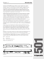
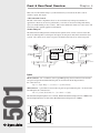
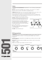
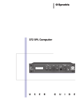
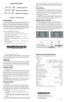
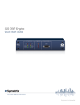
User’s Guide
501
501 Peak-RMS
Compressor/Limiter
Table of Contents
1
Chapter 2 Operator Safety Summary
2
Chapter 3 Fast Setup
3
Chapter 4 Front & Rear Panel Overview
4
Chapter 5 Dynamic Range Processing
8
Chapter 6 Applications
10
Chapter 7 Troubleshooting
12
Chapter 8 Specifications
13
Chapter 9 Warranty & Service
14
Appendix A Notes on the 501-01 (Option 1)
16
501
Chapter 1 Introduction
Rev B.00, June 17th, 1999
Symetrix part number 53501-0B00
Subject to change without notice.
©1999, Symetrix, Inc. All right reserved.
Symetrix is a registered trademark of Symetrix, Inc.
Mention of third-party products is for informational
purposes only and constitutes neither an endorsement
nor a recommendation. Symetrix assumes no
responsibility with regard to the performance or use
of these products.
Under copyright laws, no part of this manual may be
reproduced or transmitted in any form or by any
means, electronic or mechanical, including photocopying, scanning, recording or by any information
storage and retrieval system, without permission, in
writing, from Symetrix, Inc.
i
6408 216th St. SW
Mountlake Terrace, WA 98043 USA
Tel (425) 778-7728
Fax (425) 778-7727
Email [email protected]
Chapter 1
Introduction
The Symetrix 501 Peak/RMS compressor/limiter is a precision dynamic range controller
intended for use in the most demanding professional audio applications. The 501 is two
dynamics controllers in one unit. Separately controlled, simultaneous RMS detection and
peak limiting is provided so that the limiter can be set to prevent spikes and allow the
compressor to control the signals without applying more than the desired amount of gain
reduction. The 501 performs both duties with unsurpassed distortion and noise specifications. A full complement of controls gives the operator the ability to perfectly tailor dynamic
response. This isn’t a one slider device, you are in control.
Standard engineering practice often calls for the use of low ratio compression, as a creative
device, to achieve dynamic characteristics that are more pleasing to the ear. Since the 501’s
compressor is RMS responding (like the human ear) it’s easy to get a consistent, more
listenable sound. The RMS compressor section is designed to provide both manual and
automatic (program controlled) attack and release times. The wide range of the ratio and
threshold controls make the 501 usable over a 50 dB range. RMS detection, high headroom
input circuits and output drivers, give the 501 its well known sonic excellence.
However, an RMS compressor alone does not prevent clipping distortion or tape saturation.
For this reason, standard practice also dictates the use of a peak limiter, as a protection
device, to take control of transient peaks that would otherwise cause overload distortion. The
peak limiter catches even the fastest transient spikes, with its exceedingly quick 2000 dB/msec
attack time.
With both types of processing in the same package, the 501 provides both creative and
protective dynamic range control. This is one reason why the 501 has become a first choice
for vocal applications. It is also widely known as the compressor/limiter choice for bass
players, allowing the low frequency notes to sound close and full, while protecting the
player’s amp from overloading during sharp slaps and pounding of the bass strings. With
this type of performance and reliability the 501 has become the audio experts’ tool of necessity.
Backed by over two decades of audio processor design experience, the Symetrix 501 can only
be called “performance elegance” in the classic sense of audio quality and reliability.
We recommend that you read this manual cover-to-cover. You will find the answers to most
of your questions inside. Should you have any comments or questions, please do not
hesitate to contact us at the numbers/addresses below. Your calls are always welcome.
Fax:
(425) 778-7727
Email:
[email protected]
501
Phone: (425) 778-7728
Website:www.symetrixaudio.com
PEAK LIMITER
RMS COMPRESSOR/LIMITER
THRESHOLD (dBm)
-20
501
PEAK-RMS
COMPRESSOR/
LIMITER
ATTACK (dB/mSEC)
+10
.4
12
RATIO (X:1)
30
3
0
-40
RELEASE (dB/SEC)
1.5
-10
-30
.25
AUTOMATIC
ATTACK/RELEASE
MANUAL
IN
12
300
5
ACTIVE
2.2
12
1.4
STEREO
BYPASS
MONO
+2
CONNECT
IN
BYPASS
BYPASS
∞
OUTPUT
THRESHOLD (dBM)
STEREO SIDECHAIN
SLAVE
5.5
60
+20
POWER
GAIN REDUCTION (dB)
+6
-6
+14
-10
OUTPUT GAIN (dB)
0
+8
-4
25
-12
20
15
12
10
8
6
4
3
2
+12
-20
+20
CLIP
ACTIVE
Front panel
P RE S S
117 VAC
220 VAC
FUSE:
.5 AMP (117VAC)
.25 AMP (220VAC)
FUSE
SIDE-CHAIN INSERTION
STEREO
MFG. BY SYMETRIX,INC.
LYNNWOOD, WA.,USA
FABRIQUÉ AUX E.-U. PAR SYMETRIX INC., LYNNWOOD, WASHINGTON.
RÉFÉREZ TOUTE RÉPARATION À UN TECHNICIEN QUALIFIÉ.
OUTPUT
TO EQ
FROM EQ
INTERCONNECT
(OR EXT.CNTRL.)
(TIP,RING,SLEEVE)
INPUT
Rear panel
1
Operator Safety Summary
Equipment Markings
CAUTION
RISK OF ELECTRIC SHOCK
DO NOT OPEN
TO REDUCE THE RISK OF FIRE OR
SHOCK DO NOT EXPOSE
WARNING: ELECTRIC
THIS EQUIPMENT TO RAIN OR MOISTURE
DE CHOC ELECTRIQUE
AVIS: RISQUE
NE PAS OUVRIR
SEE OWNERS MANUAL. VOIR CAHIER D’INSTRUCTIONS.
No user serviceable parts inside. Refer servicing to qualified service personnel.
Il ne se trouve a l’interieur aucune piece pourvant entre reparée l’usager.
S’adresser a un reparateur compétent.
The lightning flash with arrowhead symbol within an
equilateral triangle is intended to alert the user of the
presence of uninsulated “dangerous voltage” within
the product’s enclosure that may be of sufficient
magnitude to constitute a risk of electric shock to
persons. The exclamation point within an equilateral
triangle is intended to alert the user of the presence of
important operating and maintenance (servicing)
instructions in the literature accompanying the
product (i.e. this manual).
Caution To prevent electric shock, do not use the
polarized plug supplied with the unit with
any extension cord, receptacle, or other
outlet unless the blades can be fully
inserted.
Terms
Several notational conventions are used in this
manual. Some paragraphs may use Note, Caution,
or Warning as a heading. Certain typefaces and
capitalization are used to identify certain words.
These are:
501
Note
Caution
Warning
CAPITALS
Boldface
Identifies information that needs
extra emphasis. A Note generally
supplies extra information to help
you to better use the 501.
Identifies information that, if not
heeded, may cause damage to the
501 or other equipment in your
system.
Identifies information that, if
ignored, may be hazardous to your
health or that of others.
Controls, switches or other markings
on the 501’s chassis.
Strong emphasis.
Important Safety Instructions
Please read and keep these instructions. Heed
and follow all warnings and instructions.
Install in accordance with the manufacturer’s
instructions.
Power Source This product is intended to
operate from a power source that does not apply
more than 250V rms between the power supply
conductors or between either power supply
conductor and ground. A protective ground
2
Chapter 2
connection, by way of the grounding conductor
in the power cord, is essential for safe operation.
Grounding The chassis of this product is
grounded through the grounding conductor of
the power cord. To avoid electric shock, plug the
power cord into a properly wired receptacle
before making any connections to the product. A
protective ground connection, by way of the
grounding conductor in the power cord, is
essential for safe operation. Do not defeat the
safety purpose of the grounding plug. The
grounding plug has two blades and a third
grounding prong. The third prong is provided for
your safety. When the provided plug does not fit
your outlet, consult an electrician for replacement
of the obsolete outlet.
Danger from Loss of Ground If the protective
ground connection is lost, all accessible conductive parts, including knobs and controls that may
appear to be insulated, can render an electric
shock.
Proper Power Cord Use only the power cord
and connector specified for the product and your
operating locale. Use only a cord that is in good
condition. Protect the power cord from being
walked on or pinched, particularly at plugs,
convenience receptacles, and the point where
they exit from the apparatus.
Proper Fuse The user accessible fuse is a part of
the attached AC connector. The fuseholder
accepts 5 x 20mm diameter fuses. For 117VAC
operation, the correct value is 0.5A, 250VAC,
standard. For 230VAC operation, the correct
value is 0.25A, 250VAC, standard.
Operating Location Do not operate this equipment under any of the following conditions:
explosive atmospheres, in wet locations, in
inclement weather, improper or unknown AC
mains voltage, or if improperly fused. Do not
install near any heat source such as radiators,
heat registers, stoves, or other apparatus
(including amplifiers) that produce heat. Unplug
this apparatus during lightning storms or when
unused for long periods of time.
Stay Out of the Box To avoid personal injury (or
worse), do not remove the product covers or
panels. Do not operate the product without the
covers and panels properly installed. Only use
accessories specified by the manufacturer. Clean
only with a damp cloth.
User-serviceable parts There are no user
serviceable parts inside the 501. In case of failure,
refer all servicing to the factory. Servicing is
required when the 501 has been damaged in any
way, such as when a power supply cord or plug
is damaged, liquid has been spilled or objects
have fallen into the apparatus, the apparatus has
been exposed to rain or moisture, does not
operate normally, or has been dropped.
Chapter 3
Fast Setup
Installation
The 501 is designed for mounting in a standard 19" rack, and requires only 1 rack space (1-3/4").
The 501’s “inputs,” “outputs” and SIDE-CHAIN connectors should be wired to a patch bay for ease
of operation. If you have two 501’s, you may permanently wire their STEREO INTERCONNECT jacks if
desired. The TO EQ, FROM EQ, and SIDE-CHAIN INSERTION output/input connection need not be
normalled, because it can be front panel activated with the SIDE-CHAIN switch.
Follow these instructions to get your 501 up-and-running as quickly as possible. The intent of this
section is fast setup. Refer to later chapters for explanation of the 501’s controls and functions.
n
o
p
q
r
s
t
u
v
This Fast Setup does not use the STEREO SLAVE or SIDECHAIN functions.
Connect to the output of the signal source to be processed to the input of the 501..
Connect output of the 501 to the input of the next device in the signal chain.
Push in the AUTOMATIC ATTACK/RELEASE button (sets automatic operation)
Activate the RMS Compressor/Limiter by pushing in it's IN button.
Activate the Peak limiter by pushing in it's IN button.
To find a beginning setting for the RMS COMP/LIMITER THRESHOLD, patch the 501 into your
system and feed a signal slightly above normal program level to its input. Turn the RMS
COMP/LIMITER THRESHOLD control counterclockwise until the top (2dB) LED is lighted during
peaks in the program.
Set the RMS COMP/LIMITER RATIO control to about 5:1.
To find a beginning setting for the PEAK LIMITER THRESHOLD, patch the 501 into your system
and feed a signal slightly above normal program level to its input. Turn the PEAK LIMITER
THRESHOLD counter-clockwise until the green THRESHOLD LED is illuminated during peaks in
the program.
Use the 501’s OUTPUT GAIN control to match the output level to equipment following it in
the signal chain, and to make up any gain loss that results from compression.
The LED meter will not be lighted unless the 501 is attenuating signals, and attenuation will
not occur unless at least one of the THRESHOLD controls is set to a level that will initiate
activity in either the RMS section or peak limiter. The meter is fast responding, and will
accurately track the attenuation of the VCA’s.
The green threshold indicators will be lighted whenever signals reach either the RMS or the
peak threshold, even though the 501 may not be attenuating those signals.
w
Now read the rest of this manual.
3
501
Note:
Front & Rear Panel Overview
Chapter 4
This section of the manual will give you the information you need about the 501’s controls,
switches, inputs and outputs.
A Word About the Controls
The 501’s full control complement allows it to be used effectively in the greatest number of
applications. However, the level of performance you are able to extract from it depends entirely
upon your understanding of those controls. This section defines the function of each control, and
Section 4 provides specific applications information.
The Block Diagram
The functional block diagram below illustrates the signal flow into, inside of, and out of the 501.
The levels and impedances at the inputs and outputs are designed to match all common line level
systems. All connectors are on the rear panel, all switches and controls are on the front panel.
P RESS
BALANCED
INPUT
BALANCED
OUTPUT
VCA
GAIN REDUCTION DISPLAY
PEAK
RMS
THRESHOLD LEDS
BALANCED/
UNBALANCED
INPUT
PEAK AND RMS
DETECTORS
TO
EQ
FRONT PANEL
CONTROLS
FROM
EQ
SIDE-CHAIN
INSERTION
UNBALANCED
OUTPUT
STEREO
INTERCONNECT
STEREO
SLAVE
Inputs
501
Phone connector - 1/4" 3-conductor (stereo type) TRS (tip-ring-sleeve) connector located on the
rear panel accepts balanced unbalanced signals. As shown in the block diagram below,
the connections are:
Tip = + (high) Ring = - (low) Sleeve = ground (shield).
XLR connector - 3-pin female located on the rear panel accepts balanced signals. As shown in the
block diagram, the connections are:
Pin 1 = ground (shield) Pin 2 = - (low) Pin 3 = + (high)
The unbalanced input impedance is 23.1k ohms. Maximum unbalanced input level is +20dBm. The
balanced input impedance is 16.7k ohms. Maximum balanced input level is +26dBm.
4
P RE S S
INPUT
Outputs
Connectors - 1/4" 2-conductor (mono type) TS (tip-sleeve) connector located on the rear panel. It
provides unbalanced low impedance output signals. The connections are:
Tip = + (high) Sleeve = ground (shield)
3-pin male XLR connector located on the rear panel
provides balanced output signals. As shown in the
block diagram, the connections are:
Pin 1 = ground (shield)
Pin 2 = - (low)
OUTPUT
Pin 3 = + (high)
The unbalanced output impedance is 51 ohms.
Maximum unbalanced output level is +20dBm. The
balanced output impedance is 51 ohms. Maximum
balanced output level is +26dBm into 600 ohms.
Sidechain Insertion
TO EQ - 1/4" 2-conductor (mono type) TS (tip-sleeve) connector that provides the send (output)
from the 501’s side-chain.
Output impedance is 51 ohms. Maximum output level is
+20dBm. Minimum load impedance is 600 ohms.
When the SIDECHAIN INSERTION connectors are used as a
send/receive patch point, the 501’s activity can be made
frequency dependent.
SIDE-CHAIN INSERTION
TO EQ
FROM EQ
(OR EXT.CNTRL.)
Stereo Interconnect
Phone connector - 1/4" 3-conductor (stereo type) TRS (tip-ring-sleeve) connector located on the
rear panel provides the necessary connection for operating two 501’s as a tracking stereo pair. A
standard stereo cord equipped with TRS (stereo type) connectors may be used. Stereo operation is
enabled by the STEREO SLAVE switch (see next section.)
STEREO
INTERCONNECT
(TIP,RING,SLEEVE)
5
501
FROM EQ - 1/4” 2-conductor (mono type) TS (tip-sleeve)
connector that provides the return (input) to the 501’s
sidechain. Input impedance is 9.1k ohms. Maximum input
level is +20dBm.
Switches
AUTOMATIC ATTACK/RELEASE - Puts the 501 into, or out of, automatic program dependent
operation.
IN (RMS) - Switches the 501’s RMS Compressor/Limiter control circuitry in or out. Must be
depressed, to the “in” position, or there will be no comp/limiter activity.
STEREO SLAVE - Enables stereo mode operation by switching one unit of a pair of 501’s to slave
mode. For stereo operation, only one of a pair may be switched to slave mode.
Depressing STEREO SLAVE initiates stereo operation between two 501’s that are linked via their
STEREO INTERCONNECT jacks. Releasing STEREO SLAVE returns the units to separate (mono) operation, even though they may remain interconnected.
Sidechain - Enables operation of the SIDE-CHAIN from
the front panel, allowing permanent connection of an
equalizer to the 501’s TO EQ and FROM EQ connectors.
Depressing the SIDE-CHAIN switch puts any device
connected to the SIDE-CHAIN INSERTION (TO EQ and FROM
EQ) connectors into the control circuit path, while
releasing it disconnects that circuit path, returning the
501 to “normal” operation.
STEREO SIDECHAIN
SLAVE
IN
2
STEREO
BYPASS
MONO
CONNECT
IN
BYPASS
BYPASS
IN (Peak) - Switches the 501’s peak limiter circuitry in
or out. Must be depressed, to the “in” position, to
activate peak limiting.
POWER- Switches AC mains on/off.
RMS Compressor/Limiter
501
THRESHOLD - Sets the level above which the RMS comp/limiter activity is initiated. The associated green LED illuminates when the level at the input equals the RMS compressor/limiter’s
threshold level.
ATTACK - Sets the time required for the onset of RMS compressor/limiter activity (from 12dB/
msec. to .25dB/msec.).
RELEASE - Sets the time required for the RMS compressor/limiter to return to unity gain (from
300dB/sec. to 5dB/sec.).
RATIO - Sets the RMS compressor/limiter’s ratio from 1.4:1 to 20:1.
6
RMS COMPRESSOR/LIMITER
THRESHOLD (dBm)
-20
0
-40
RELEASE (dB/SEC)
RATIO (X:1)
1.5
30
5.5
-10
-30
ACTIVE
ATTACK (dB/mSEC)
+10
3
.4
12
.25
AUTOMATIC
ATTACK/RELEASE
MANUAL
IN
60
12
300
5
2.2
12
1.4
∞
BY
Peak Limiter
THRESHOLD - Sets the peak limiter threshold from -10dBm to
+20dBm.
PEAK LIMITER
The associated green LED illuminates when the level at the input
equals the peak limiter’s threshold level.
THRESHOLD (dBM)
+2
ASS
+8
+14
-4
+20
-10
ACTIVE
Output and Metering
OUTPUT GAIN - Sets the 501’s output stage gain from -20dB to +20dB.
CLIP - Illuminates when output levels rise to within 6dB of the onset of clipping. The red LED
associated with the OUTPUT GAIN control indicates the onset of clipping in the 501’s output stage.
Reduce output gain if the red CLIP LED is lighted.
The LED GAIN REDUCTION
(dB) metering arrangement indicates the actual
level change (attenuation) being created by
the VCA. With signals
present, the LED’s will be
lighted whenever signals
are above either the RMS
or peak threshold.
OUTPUT
OUTPUT GAIN (dB)
GAIN REDUCTION (dB)
0
+6
-6
25
-12
20
15
12
10
8
6
4
3
2
+12
-20
+20
CLIP
The 501 is designed to be used post-preamp, at a place in the system where the signals have
already been amplified to line levels. But, “line level” is a generic term that’s been used at one time
or another to describe signals ranging anywhere from -40dBm to +20dBm. As a result there’s really
no way for us to predict what the actual operating levels in your system will be. The very wide
range of the 501’s two THRESHOLD controls allows you to make it work with any “line level.”
(Microphones and guitars, for example, are not line level and should not be plugged directly into
the 501. Doing so will not damage the unit, but will result in excessive noise.)
The overall level in any signal chain is determined to a large extent by the transient content of the
program material. Transients are very short duration signals. Peak reading LED type meters will
usually respond to transients, but VU meters are designed to indicate average levels and therefore
will not respond to transients. As a result, transients are long gone before a VU meter can respond.
Likewise, the 501’s peak limiter will respond to very short duration signals, while the RMS section
will not.
Drums, and percussive instruments like piano or banjo, generate the kind of very large transients
which are not shown in their entirety by a VU meter, but which may nonetheless be controlled by
the 501’s peak limiter. Signals from these instruments may trigger the 501 when the THRESHOLD
controls are set at 0 (or above), even though your VU meter says the level never goes above 0. On
the other hand, instruments like violins do not create large transients, so the correlation between
the VU meter reading and the green threshold indicator appears to be more accurate.
7
501
Signal Levels
Dynamic Range Processing
Chapter 5
The Model 501 Peak/RMS compressor limiter is a precision dynamic range controller intended for
use in professional audio applications. This section of the manual provides a general discussion
of dynamic range processing, and some specifics on compressors and limiters.
Defining Dynamic Range
To begin a discussion of dynamic range processors it’s necessary to have a working definition of
dynamic range. The term is really self-descriptive, but has two distinctly different uses:
1.
To describe the actual range of signal fluctuations that are going through the equipment,
and
2.
To define the maximum allowable range of signal fluctuations that can be put through the
equipment.
The usual unit of measure for audio signals is the decibel (dB).
Dynamic Range as a Specification
The maximum usable range of operation for a particular circuit or piece of gear is the distance in dB
between its noise floor and its maximum output level. In this context, dynamic range is used as an
equipment specification.
Noise floor is defined as the lower limit of a circuit’s operating level, and is a function of its selfgenerated electrical noise. Very noisy (poorly designed) circuits have a high noise floor, while quiet
(well designed) circuits have a low noise floor. Maximum output level is the upper limit of the operating
range, and is the level at which clipping begins.
To put levels in perspective they must be referenced to some nominal operating level, like 0dBm - that’s
why noise specs are stated as minus something. Since maximum output level is usually greater than
0dBm, it’s stated as plus something. The difference between the noise floor and the onset of clipping is
the dynamic range.
Dynamic Range of Sound and Signals
501
The other definition of dynamic range describes level changes, or the range over which signals
actually fluctuate. The signals under discussion here are electrical representations of sounds, so it
follows that sound has dynamic range. The dynamic range of the human voice, from a whisper to a
shout, is well over 100dB. That means a microphone will convert the sound of a voice going from a
whisper to a shout into an electrical output signal, whose dynamic range is well over 100dB.
Why Dynamic Range Processors are Necessary
For signals to stay below distortion and above noise, their actual dynamic range must be kept within the
specified dynamic range of the circuits through which those signals flow. Unfortunately, the actual
dynamic range of real world signals often exceeds the available dynamic range of even the best
equipment.
For example, the dynamic range of the best analog tape recorders is around 80dB, while digital recorders
top out at around 96dB. As good as these machines are, there’s still not quite enough room for very
wide dynamic range signals. In order to maintain a 60dB signal-to-noise ratio (to keep the signals 60dB
above the noise floor), the dynamic range of signals stored on the analog tape machine would have to
be restricted by 20dB, while the digital recorder would be restricted by 36dB. A compressor or limiter is
often used to reduce dynamic range by setting an upper limit on signal levels.
The Threshold Concept
The “threshold” is the level at which a dynamic range processor’s activity begins. In operation,
the dynamic range processor’s sensing circuitry constantly “looks at” the incoming signal and
compares it to a reference level, which is called the threshold level. In practice that reference level
is set by the operator with the threshold control. Compressors and limiters respond only when
signals at their input are above threshold.
8
The Voltage Controlled Amplifier (VCA)
The gain reduction capability of a dynamic range processor derives from one of the amplifier
circuits inside the unit, whose gain is controlled by a DC voltage. That part of the circuit is called a
voltage controlled amplifier, or VCA. Inside the 501, a separate buffered audio signal is sent to a
group of circuits that comprise the peak and RMS detectors. The detectors turn the AC audio
signal into DC control voltages, which are sent to the VCA under the direction of the front panel
controls. The VCA then, is actually governed by signals that are derived from the audio signal,
and placed under operator control via the front panel controls.
Compressors and Limiters
Compressors and limiters are designed to reduce the dynamic range of their output whenever the
input signal is above threshold. Compressors decrease signal levels by some ratio, which is
usually adjustable. In other words, the ratio of the input level to the output level can be changed
by the user. A compressor operating with a 2:1 ratio would allow only a 1dB increase in output
level for every 2dB increase in input level.
Limiters usually have a nonadjustable ratio that is very high (greater than 10:1), and is sometimes
infinity:1. At 10:1, the limiter allows only a 1dB increase in the output level for every 10dB increase
in the input level, while at infinity:1 the limiter will not allow the output level to increase no matter
what happens with the input level.
Limiters can be thought of as very high ratio, high threshold compressors. They are intended to
“stay out of the way” until the level goes above threshold. However, above threshold their action
is very definite, providing an operator adjustable ceiling on levels.
Sidechain Processing
Look at the section “Block Diagram” on page 4. Notice the circuit that is taken from the audio
signal at the input, routed through the “TO EQ” and “FROM EQ” connectors, sent through the
peak and RMS detector circuits, then on to the VCA via the front panel control circuits. This
control signal is derived from, but totally separate from, the audio signal path.
The detector circuitry measures both the peak level and the RMS level of the audio signal, then
puts out control voltages that are directly proportional to those values. But, the control signal that
comes out of the detectors contains no audio. That means the character of the signal that’s on its
way to the detector circuits can be processed outside the 501 without actually processing the
signal that’s going through the VCA (the audio signal itself). This presents some very interesting
possibilities for changing or improving the operation of the unit.
The best use of the sidechain is to make the action of the 501 frequency dependent, that is, to make
it respond more (or less) to certain frequencies. Because the detector simply puts out a control
voltage in response to the input signal, removing certain frequencies from the signal before they
reach the detector prevents the detector from using those frequencies to create the control voltage.
On the other hand, boosting certain frequencies in the sidechain makes the system more responsive when those frequencies are present.
Since the audio signal and the control signal remain completely separate (even while the control
circuit tells the VCA whether to turn the gain up or down), you can equalize the sidechain without
actually equalizing the signals in the main audio path. See the chapter “Applications” for specific
information on the use of EQ in the sidechain.
9
501
The sidechain is a patch point in the control circuit of a dynamic range processor that provides
access to the part of the circuitry that tells the VCA what to do. The 501’s sidechain signal is
routed through a pair of rear panel connectors that allow it to be processed outside the unit, much
like the send/return patch point in a mixer’s input channel allows signals to be routed through a
compressor/limiter.
Applications
Chapter 6
By virtue of its separate RMS compressor/limiter and peak limiter, the 501 offers precision dynamic
range control over a very wide range of signals. In addition, the availability of program-controlled
automatic attack and release times makes the 501 very easy to use in situations where the nature of
the signals is unpredictable, or the operator is unable to make changes manually.
The term “program-controlled” means the 501 changes the way it responds to various types of
signals by analyzing them at the input, then adjusting its attack and release times to match the
characteristics of those signals.
In automatic mode, the 501 responds quickly to signals with high transient content like drums,
piano, banjo, and percussive synthesizer sounds. With signals like strings, that have a low
transient content, it responds gently.
RMS Compressor/Limiter vs. Peak Limiter
The RMS section of the 501 is intended to provide the general “gain riding” type of dynamic range
control that is normally applied to vocals, electric bass, solo guitar, voice-overs, etc. It is designed
to be kind to your signals, and to provide unnoticeable gain reduction even at high ratios, when
properly used.
Above threshold, the dynamic range of the output (vs. the input) will be reduced by the ratio
indicated on the front panel. At higher ratios (above 12:1) the RMS section will behave more like a
limiter than a compressor. This type of operation can be combined with the peak limiter to provide
very effective “brick wall” limiting in situations where over-modulation is dangerous, illegal, or
both. In any case, when the 501 is used appropriately, and the various controls are set carefully,
natural sounding gain control is easily achieved.
The peak limiter is intended to allow the operator to set an absolute maximum upper limit on levels
in the signal chain. Its ratio is preset at infinity:1, and its time constants (attack and release) are
intentionally quick. Above threshold the peak limiter allows no further increase in level. But
remember, the peak limiter is not designed to be kind to your signals when it’s used for more than
10dB of gain reduction.
Experience has shown that the peak limiter is best used to achieve small amounts of gain reduction
(on the order of 6dB to 8dB). The RMS compressor/limiter is best used, in conjunction with the
peak limiter, to achieve greater amounts of gain reduction.
501
General Purpose Gain Reduction
When the 501 is operated at low ratios with material that contains occasional peaks, or when the
RMS compressor/limiter is used with an intentionally slow attack time, it is often appropriate to use
the peak limiter to set a ceiling. While the RMS compressor/limiter goes about its job of smoothing
the general dynamics, the peak limiter prevents transients from overloading the signal chain.
For general purpose smoothing, set the ratio between 5:1 and 12:1. Set the threshold so maximum
gain reduction is around 10dB. The 501’s automatic mode is very useful for this kind of work, and
will usually provide more natural sounding results than manual adjustment of the attack and
release times.
When peak limiting is desired, set the peak limiter’s threshold so the green threshold indicator
illuminates about 3dB below the desired maximum level.
Using the Sidechain
The TO EQ and FROM EQ sidechain access jacks allow an equalizer to be inserted in the control
circuit of the 501. Remember that the activity of the 501 can be made more or less sensitive to
certain frequencies, when an equalizer is used to boost or cut those frequencies in the sidechain.
However, even though its activity may have been initiated by a certain frequency or group of
frequencies, the 501 treats all frequencies the same once compression or limiting has begun.
10
However, with very careful setting of the threshold controls, the 501 can perform frequency
selective compression. As an example, suppose a tape being processed has been recorded with
too much cymbal sound on the drum tracks. By using an equalizer to make the compressor more
sensitive to the cymbal frequencies, it will compress “sooner” whenever the cymbals are played.
This happens because the frequency range occupied by the cymbals is made “louder” than the rest
of the signals in the sidechain.
Because the cymbals are being compressed while the rest of the drums are not, the relative balance
between the cymbals and the rest of the drums is changed, making the drums seem louder. Conversely, if the track has too little cymbal sound, the equalizer could be used to either cut the cymbal
frequencies, or to boost the rest of the spectrum. The same kind of change in relative balance will
be achieved.
Stereo Operation with Two 501’s
It is often necessary to have two identical channels of compression or limiting available for stereo
mixdown, or for processing stereo material. For stereo operation, two units must be linked via their
rear panel “stereo interconnect” jacks, and one of them must be put into slave mode with the front
panel “stereo slave” switch.
The 501 whose STEREO SLAVE switch is in the “out” position becomes the master unit. With the
exception of the OUTPUT GAIN controls, all functions of both 501’s are now controlled by the master
unit. Slave unit THRESHOLD LEDs may flash even though the THRESHOLD control is not active. To
use an equalizer in the sidechain, it is only necessary to put one EQ into the sidechain of the
master unit.
501
Depressing the STEREO SLAVE switch on both units will render both inactive. One unit must be
operated as the slave, the other as the master.
11
Troubleshooting
Chapter 7
Make the following tests one at a time to isolate a problem you think may be caused by the 501 (or
any other unit).
1.
Make sure the unit is plugged in, the power switch is turned on and the pilot LED is
lighted.
2.
Bypass the device in question by directly connecting the cable feeding the input to the
cable feeding the output with a double female adapter. Listen to the system with this
direct connection in place. If signal passes through this direct connection, but not
through the unit, the trouble is with the unit.
3.
Check INPUT, OUTPUT and SIDECHAIN wires and connectors carefully.
Note
Most malfunctions are wire or connector related.
4.
Plug headphones directly into outputs to see if there is signal present. If you cannot hear
the signal at the unit’s output, work your way back through the chain until you can hear it. (If you
get all the way back to the input without hearing anything, get competent help.)
Use the following table to analyze difficulties before calling Symetrix or a technician for help.
What to check - what to do
1. No sound at output
Is the unit turned on? Is there something in the sidechain that’s
not turned on?
2. No compress/limit action
Is the “channel in” switch depressed? Is there something in the
sidechain that’s not turned on? Is the “comp/limit threshold”
set low enough for the present signal level?
3. Low or distorted output
Be sure gear patched into the sidechain is turned on. Check
INPUT, OUTPUT and SIDECHAIN connectors for shorts. Is
something patched into the signal chain before or after the 501?
Is the 501 powered up?
4. Distortion or crackling
sound at output
Check level and signal at input. Is it too high? Is it distorted?
501
Problem
12
Chapter 8
Specifications
501 Specifications
Input/Output
Inputs
XLR-female, >20-kilohms line-level
Balanced Bridging, >20-kilohms Unbalanced Bridging
TRS-female paralleled with XLR connector
Outputs
200-Ohm Source Impedance, Balanced, XLR-male
TS-female (Unbalanced) Transformer Balanced Optional
100-Ohm Source Impedance
Maximum Input Level
+20 dBu, Balanced
Maximum Output Level
+26 dBm Balanced (600 Ohms)
(onset of clipping/1% THD)
+20 dBm Unbalanced (600 Ohms)
Sidechain
100-Ohm Source Impedance
7-kilohm Input Impedance
Separate TS, Unbalanced, Send and Receive jack
Connectors
Input: XLR-3F, ¼" TRS
Output: XLR-3M, ¼" TS
Sidechain: ¼" TS (two)
Compressor
Type
Manual Attack Time
Manual Release Time
Auto-Release Time
Threshold
Ratio
Limiter
Attack Time
Release Time
Threshold
Ratio
RMS responding, soft-knee
Variable: .25 to 12 dB/ms
Variable: 5 to 300 dB/sec
Program dependent
-40 dBu to +10 dBu
1.4:1 to ∞:1
Performance Data
Frequency Response
20 Hz to 20 kHz (+0, -1 dB)
THD+Noise
0.025 %, +0 dBm in, +0 dBm out, 10 dB gain reduction,
1 kHz, 30 kHz low-pass filter
<0.09 %, +0 dBm in, +0 dBm out,
10 dB gain reduction, 20 kHz (distortion
products primarily 2nd harmonic)
Equivalent Input Noise (EIN) Better than -85.5 dBu, 600-Ohm Source
Impedance, Unity Gain Better than -95.5 dBu,
600-Ohm Source Impedance, 20 dB gain reduction
Physical
Size (hwd) 1.74 x 19 x 4.75 inches, 4.42 x 48.3 x 12.065 centimeters
Weight
7 lbs (15.4kg) shipping
Electrical
Power Requirements
117V nominal, 120V AC,
60 Hz, 12.5 watts maximum
230V nominal, 240V AC, 50 Hz, 12.5 watts maximum
Note:
The maximum operating ambient temperature is 25
degrees C.
In the interest of continuous product improvement, Symetrix, Inc.
reserves the right to alter, change, or modify these specifications
without prior notice.
2000 dB/ms (approximately 1/2 cycle at 50 kHz)
110 dB/sec
-10 dBu to +20 dBu
∞:1
501 Architects and Engineers Specifications
The unit shall have a RMS responding compressor section with separate controls for ratio,
threshold, attack, and release. A front panel switch shall be provided to engage the auto attack/
release time mode. The ratio shall be adjustable from 1.4:1 to infinity:1. The peak limiter shall have
a fixed infinity:1 ratio, fixed attack rate of 2000dB/ms, and adjustable threshold (-10dBm to +20dBm).
The inputs shall be active balanced bridging designs terminated with 3-pin XLR (AES/IEC standard
wiring), and ¼" TRS. The input circuitry shall incorporate RFI filters. The output shall be an active
balanced design, terminated with 3-pin XLR (balanced output, AES/IEC standard wiring), and a ¼"
TS jack (unbalanced output). The active-balanced output shall be capable of delivering +26 dBm,
balanced, into a 600 Ohm load. A transformer-coupled output shall be available as an option. There
shall be separate ¼" TS female connectors provided for the sidechain send and return.
The unit shall be capable of being linked with another like unit for stereo operation. In this mode,
the overall gain reduction of the two channels shall be based upon the mono-sum of the two input
signals and each unit shall receive identical gain-reduction control signals. The stereo-link function
shall be controllable via a front-panel switch.
Overall frequency response shall be 20Hz to 20kHz (0dB, -1dB). THD shall not exceed .025% with
10dB gain reduction, 600 ohm load, 1kHz tone at 0dBm. The equivalent input noise (EIN) shall be 85.5dBU or better at unity gain with a 600 Ohm source over a 22-20kHz noise bandwidth.
The AGC shall be capable of operating by means of its own built-in power supply connected to
117V nominal AC (105-130V) 50/60 Hz (230V nominal, 207-253V AC, 50 Hz where applicable).
The unit shall be a Symetrix Incorporated model 501 Peak RMS Compressor/Limiter.
13
501
The compressor/limiter shall be a single channel unit that reduces the dynamic range of wideband,
wide range audio signals. It shall have separate compressor and peak limiter sections and occupy a
single rack space (1U).
Warranty & Service
Chapter 9
501 Limited Warranty
Symetrix, Inc. expressly warrants that the product will be free from defects in material and workmanship for one (1) year. Symetrix's obligations under this warranty will be limited to repairing or
replacing, at Symetrix's option, the part or parts of the product which prove defective in
material or workmanship within one (1) year from date of purchase, provided that the Buyer
gives Symetrix prompt notice of any defect or failure and satisfactory proof thereof. Products
may be returned by Buyer only after a Return Authorization number (RA) has been obtained
from Symetrix. Buyer will prepay all freight charges to return the product to the Symetrix
factory. Symetrix reserves the right to inspect any products which may be the subject of any
warranty claim before repair or replacement is carried out. Symetrix may, at its option, require
proof of the original date of purchase (dated copy of original retail dealer's invoice). Final
determination of warranty coverage lies solely with Symetrix. Products repaired under warranty
will be returned freight prepaid by Symetrix via United Parcel Service (surface), to any location
within the Continental United States. At Buyer's request the shipment may be returned via
airfreight at Buyer's expense. Outside the Continental United States, products will be returned
freight collect.
The foregoing warranties are in lieu of all other warranties, whether oral, written, express,
implied or statutory. Symetrix, Inc. expressly disclaims any IMPLIED warranties, including
fitness for a particular purpose or merchantability. Symetrix's warranty obligation and
buyer's remedies hereunder are SOLELY and exclusively as stated herein.
This Symetrix product is designed and manufactured for use in professional and studio audio
systems and is not intended for other usage. With respect to products purchased by consumers for personal, family, or household use, Symetrix expressly disclaims all implied warranties, including but not limited to warranties of merchantability and fitness for a particular
purpose.
This limited warranty, with all terms, conditions and disclaimers set forth herein, shall extend
to the original purchaser and anyone who purchases the product within the specified warranty
period.
Warranty Registration must be completed and mailed to Symetrix within thirty (30) days of the
date of purchase.
501
Symetrix does not authorize any third party, including any dealer or sales representative, to
assume any liability or make any additional warranties or representation regarding this product
information on behalf of Symetrix.
This limited warranty gives the buyer certain rights. You may have additional rights provided
by applicable law.
Limitation of Liability
The total liability of Symetrix on any claim, whether in contract, tort (including negligence) or
otherwise arising out of, connected with, or resulting from the manufacture, sale, delivery,
resale, repair, replacement or use of any product will not exceed the price allocable to the
product or any part thereof which gives rise to the claim. In no event will Symetrix be liable for
any incidental or consequential damages including but not limited to damage for loss of
revenue, cost of capital, claims of customers for service interruptions or failure to supply, and
costs and expenses incurred in connection with labor, overhead, transportation, installation or
removal of products or substitute facilities or supply houses.
14
Servicing the 501
If you have determined that your 501 requires repair services and you live outside of the
United States please contact your local Symetrix dealer or distributor for instructions on how
to obtain service. If you reside in the U.S. then proceed as follows:
At the Symetrix factory, Symetrix will perform in-warranty or out-of-warranty service on any
product it has manufactured for a period of five years from date of manufacture.
Before sending anything to Symetrix, contact our Customer Service Department for a return
authorization (RA) number. The telephone number is (425) 778-7728, Monday through Friday,
8AM (800 hours) though 4:30 PM (1630 hours), Pacific Time.
In-Warranty Repairs
To get your 501 repaired under the terms of the warranty:
1.
Call us for an RA number.
2.
Pack the unit in its original packaging materials.
3.
Include your name, address, daytime telephone number, and a brief
statement of the problem.
4.
Write the RA number on the outside of the box.
5.
Ship the unit to Symetrix, freight prepaid.
We do not accept freight collect shipments.
If you choose to send us your product in some sort of flimsy packaging, we’ll have to charge
you for proper shipping materials. If you don’t have the factory packaging materials, then do
yourself a favor by using an oversize carton, wrap the unit in a plastic bag, and surround it
with bubble-wrap. Pack the box full of Styrofoam peanuts. Be sure there is enough clearance in
the carton to protect the rack ears (you wouldn’t believe how many units are returned with
bent ears). We won’t return the unit in anything but Symetrix packaging for which we will have
to charge you. Of course, if the problem turns out to be operator inflicted, you’ll have to pay
for both parts and labor. In any event, if there are charges for the repair costs, you will pay for
the return freight. All charges will be COD unless you have made other arrangements (prepaid,
Visa or Mastercard).
Out-of-Warranty Repairs
If the warranty period has passed, you'll be billed for all necessary parts, labor, packaging
materials, and freight charges. Please remember, you must call for an RA number before
sending the unit to Symetrix.
15
501
Just do these five things, and repairs made in-warranty will cost you only one-way freight
charges. We’ll prepay the return (surface) freight.
Notes on the 501-01 (Option 1)
Appendix A
501
The 501-01 is identical to the 501 except that the Option 1 type uses a transformer in place of the
electronically balanced output in the 501 standard unit. The Option 1 configuration is shown on a
schematic available from our Technical Service department. Two differences define the two
configurations: In the 501-01 the output coupling capacitors are omitted. In their place is the
above-mentioned output transformer. Also, R103 or R104 will be found factory-selected to trim the
DC offset voltage at either end of the output transformer primary to zero volts DC.
16
17
501
501
18
Symetrix, Inc.
6408 216th St. SW
Mountlake Terrace, WA, 98043
USA
Tel: (425) 778-7728
Fax: (425) 778-7727
Website: http://www.symetrixaudio.com
Email: [email protected]