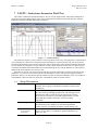
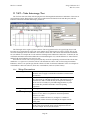
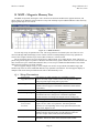
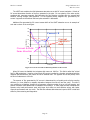
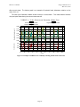
1
Relative Inductance Analyzer (RIA)
User’s Manual
Integral Solutions Int'l
– RIA-2008 version 1.2.2 –
March 31, 2010
Copyright ©2009-2010 Integral Solutions Int'l
All rights reserved
Integral Solutions Int'l
3000 Olcott St
Santa Clara, CA 95054
Phone: (408) 653-0300
Fax: (408) 653-0309
Web: http://www.us-isi.com/
E-mail: [email protected]
While every effort has been made to verify the accuracy of the information contained in this publication, this publication may contain
technical and/or typographical errors. Please contact Integral Solutions Int’l to report any errors in this publication.
RIA User’s Manual
Integral Solutions Int’l
March 31, 2010
Contents
1 INTRODUCTION ....................................................................................................................................... 6 1.1 2 INSTALLATION......................................................................................................................................... 8 2.1 2.2 2.3 2.4 2.5 2.6 3 SETUP PARAMETERS ............................................................................................................................. 34 RESULTS ............................................................................................................................................... 35 EXAMPLE PRINTOUT ............................................................................................................................. 36 CYCET – COIL-YOKE COUPLING EFFICIENCY TEST ................................................................. 37 8.1 8.2 8.3 9 SETUP PARAMETERS ............................................................................................................................. 32 RESULTS ............................................................................................................................................... 33 EXAMPLE PRINTOUT ............................................................................................................................. 33 LSATF – INDUCTANCE SATURATION FIELD TEST ...................................................................... 34 7.1 7.2 7.3 8 SETUP PARAMETERS ............................................................................................................................. 30 RESULTS ............................................................................................................................................... 31 EXAMPLE PRINTOUT ............................................................................................................................. 31 LSATI – INDUCTANCE SATURATION I-BIAS TEST....................................................................... 32 6.1 6.2 6.3 7 SETUP PARAMETERS ............................................................................................................................. 28 RESULTS ............................................................................................................................................... 29 LSAT – INDUCTANCE SATURATION TEST ..................................................................................... 30 5.1 5.2 5.3 6 STARTING SOFTWARE ........................................................................................................................... 20 INSTALLING HGAS ............................................................................................................................... 21 RUNNING TESTS ................................................................................................................................... 22 WRITER SPECIFIC TESTS ....................................................................................................................... 23 RIA-2008 CUSTOM STRESS .................................................................................................................. 24 RUNTIME LICENSE ................................................................................................................................ 25 RUNNING RIA ON BLAZERX6 AND WAFER .......................................................................................... 26 RIA-2008 SETUP ....................................................................................................................................... 28 4.1 4.2 5 REQUIREMENTS ...................................................................................................................................... 8 ARRIVAL CHECKLIST ............................................................................................................................ 10 CONNECTIONS ...................................................................................................................................... 10 CONNECTION DIAGRAM ....................................................................................................................... 12 RUNNING 1ST TIME ................................................................................................................................ 13 INSTALLING RIA UPGRADE .................................................................................................................. 14 TESTER BASICS ...................................................................................................................................... 18 3.1 3.2 3.3 3.4 3.5 3.6 3.7 4 RELATED DOCUMENTATION ................................................................................................................... 7 SETUP PARAMETERS ............................................................................................................................. 37 RESULTS ............................................................................................................................................... 38 EXAMPLE PRINTOUT ............................................................................................................................. 39 YDT – YOKE DEFECT TEST ................................................................................................................. 40 9.1 9.2 9.3 SETUP PARAMETERS ............................................................................................................................. 40 RESULTS ............................................................................................................................................... 40 EXAMPLE PRINTOUT ............................................................................................................................. 41 10 TMFT – TILTED MAGNETIC FIELD TEST ....................................................................................... 42 10.1 10.2 10.3 SETUP PARAMETERS ............................................................................................................................. 42 RESULTS ............................................................................................................................................... 42 EXAMPLE PRINTOUT ............................................................................................................................. 43 Page 2
RIA User’s Manual
Integral Solutions Int’l
March 31, 2010
11 YAT – YOKE ANISOTROPY TEST ...................................................................................................... 44 11.1 11.2 11.3 SETUP PARAMETERS ............................................................................................................................. 44 RESULTS ............................................................................................................................................... 45 EXAMPLE PRINTOUT ............................................................................................................................. 45 12 YAT SWEEP – YOKE ANISOTROPY BIAS SWEEP TEST .............................................................. 46 12.1 12.2 12.3 SETUP PARAMETERS ............................................................................................................................. 46 RESULTS ............................................................................................................................................... 47 EXAMPLE PRINTOUT ............................................................................................................................. 47 13 YHDFT – YOKE HYSTERESIS-DOMAIN FIELD TEST ................................................................... 48 13.1 13.2 13.3 SETUP PARAMETERS ............................................................................................................................. 48 RESULTS ............................................................................................................................................... 48 EXAMPLE PRINTOUT ............................................................................................................................. 49 14 YHDIT – YOKE HYSTERESIS-DOMAIN I-BIAS TEST .................................................................... 50 14.1 14.2 14.3 SETUP PARAMETERS ............................................................................................................................. 50 RESULTS ............................................................................................................................................... 50 EXAMPLE PRINTOUT ............................................................................................................................. 51 15 MMT – MAGNETIC MEMORY TEST.................................................................................................. 52 15.1 15.2 15.3 SETUP PARAMETERS ............................................................................................................................. 52 RESULTS ............................................................................................................................................... 53 EXAMPLE PRINTOUT ............................................................................................................................. 53 16 WRITER_RES – WRITER RESISTANCE TEST ................................................................................. 54 16.1 16.2 16.3 SETUP PARAMETERS ............................................................................................................................. 54 RESULTS ............................................................................................................................................... 54 EXAMPLE PRINTOUT ............................................................................................................................. 55 17 CALIBRATION......................................................................................................................................... 56 17.1 17.2 17.3 INDUCTANCE ........................................................................................................................................ 56 MAGNET ............................................................................................................................................... 57 MAGNET ALIGNMENT........................................................................................................................... 59 18 TOOLS ....................................................................................................................................................... 60 18.1 18.2 18.3 18.4 QPS SPLITTER OPTION ......................................................................................................................... 60 ISI2010 DIAGNOSTICS .......................................................................................................................... 61 HALL EFFECT CARTRIDGE .................................................................................................................... 61 QUAD-POLE MAGNET CALIBRATION ADAPTOR ................................................................................... 62 19 TROUBLESHOOTING ............................................................................................................................ 63 19.1 FAQ ..................................................................................................................................................... 63 20 APPENDIX A – RIA MEASUREMENTS............................................................................................... 64 20.1 20.2 20.3 20.4 20.5 20.6 20.7 20.8 20.9 PERPENDICULAR WRITE HEAD STRUCTURE ......................................................................................... 64 INDUCTANCE SATURATION USING DC WRITE CURRENT – LSATI TEST .............................................. 67 INDUCTANCE SATURATION IN MAGNETIC FIELD – LSATF TEST (PATENT PENDING) ............................ 69 CYCET: COIL-YOKE COUPLING EFFICIENCY TEST (PATENT PENDING) ............................................... 73 YDT: YOKE DEFECT TEST (PATENT PENDING) ..................................................................................... 75 YAT: YOKE ANISOTROPY TEST (PATENT PENDING) ............................................................................. 77 MMT – MAGNETIC MEMORY TEST (PATENT PENDING) ........................................................................ 81 YHDFT AND YHDIT: YOKE DOMAIN TESTS (FIELD AND WRITE CURRENT) (PATENT PENDING) ......... 82 APPENDIX ............................................................................................................................................. 84 Page 3
RIA User’s Manual
Integral Solutions Int’l
March 31, 2010
21 APPENDIX B - RIA FAQ ......................................................................................................................... 85 22 APPENDIX C – GEN3 PROBE CARD RIA COMPATIBILITY ......................................................... 89 23 LIMITED WARRANTY........................................................................................................................... 90 Page 4
RIA User’s Manual
Integral Solutions Int’l
March 31, 2010
Figures
FIGURE 1-1 – TESTER FOOTPRINT ............................................................................................................................................... 6 FIGURE 1-2 – COMPLETE SYSTEM ............................................................................................................................................... 6 FIGURE 2-1 – RIA SYSTEM CONNECTIONS ................................................................................................................................ 12 FIGURE 3-1 – RIA CONFIGURATION (CH0 VS CH1) .................................................................................................................. 19 FIGURE 3-2 – SYSTEM MENU SELECTION .................................................................................................................................. 20 FIGURE 3-3 – ADD-INS Æ SELECTED MODULES ....................................................................................................................... 20 FIGURE 3-4 – INSTALLING AN HGA .......................................................................................................................................... 21 FIGURE 3-5 – INSTALLING AN HGA .......................................................................................................................................... 21 FIGURE 3-6 – HEAD SELECTION ................................................................................................................................................ 21 FIGURE 3-7 – RUNNING THE TESTS ........................................................................................................................................... 22 FIGURE 3-8 – ADD-INS ............................................................................................................................................................. 23 FIGURE 3-9 – ADAPTIVE PARAMETERS ..................................................................................................................................... 23 FIGURE 3-10 – RIA-2008 CUSTOM STRESS ............................................................................................................................... 24 FIGURE 3-11 – RIA-2008 RUNTIME LICENSE ............................................................................................................................ 25 FIGURE 3-12 – RIA2008 SERIAL NUMBER ................................................................................................................................ 25 FIGURE 3-13 – RIA2008 EVALUATION ..................................................................................................................................... 25 FIGURE 3-14 – RIA ON BLAZER ................................................................................................................................................ 26 FIGURE 3-15 – ALTERNATIVE TEST SITE ................................................................................................................................... 26 FIGURE 3-16 – RIA ON BLAZERX5 PRODUCTION TEST ............................................................................................................. 27 FIGURE 3-17 – RIA AND BARCONT ........................................................................................................................................... 27 FIGURE 4-1 – RIA-2008 SETUP ................................................................................................................................................ 28 FIGURE 5-1 – LSAT TEST ........................................................................................................................................................ 30 FIGURE 5-2 – LSAT EXAMPLE ................................................................................................................................................. 31 FIGURE 6-1 – LSATI PARAMETERS .......................................................................................................................................... 32 FIGURE 6-2 – LSATI EXAMPLE PRINTOUT................................................................................................................................ 33 FIGURE 7-1 – LSATF PARAMETERS ......................................................................................................................................... 34 FIGURE 7-2 – LSATF EXAMPLE PRINTOUT ............................................................................................................................... 36 FIGURE 8-1 – CYCET PARAMETERS ........................................................................................................................................ 37 FIGURE 8-2 – CYCET EXAMPLE PRINTOUT .............................................................................................................................. 39 FIGURE 9-1 – YDT PARAMETERS ............................................................................................................................................. 40 FIGURE 9-2 – YDT EXAMPLE PRINTOUT................................................................................................................................... 41 FIGURE 10-1 – TMFT PARAMETERS ......................................................................................................................................... 42 FIGURE 10-2 – TMFT EXAMPLE PRINTOUT .............................................................................................................................. 43 FIGURE 11-1 – YAT PARAMETERS ........................................................................................................................................... 44 FIGURE 11-2 – YAT EXAMPLE PRINTOUT................................................................................................................................. 45 FIGURE 12-1 – YAT SWEEP PARAMETERS ................................................................................................................................ 46 FIGURE 12-2 – YAT SWEEP EXAMPLE PRINTOUT ..................................................................................................................... 47 FIGURE 13-1 – YHDFT PARAMETERS ...................................................................................................................................... 48 FIGURE 13-2 – YHDFT EXAMPLE PRINTOUT............................................................................................................................ 49 FIGURE 14-1 – YHDIT PARAMETERS ....................................................................................................................................... 50 FIGURE 14-2 – YHDIT EXAMPLE PRINTOUT ............................................................................................................................ 51 FIGURE 15-1 – MMT PARAMETERS .......................................................................................................................................... 52 FIGURE 15-2 – MMT EXAMPLE PRINTOUT ............................................................................................................................... 53 FIGURE 16-1 – WRITER_RES PARAMETERS............................................................................................................................... 54 FIGURE 16-2 – WRITER_RES EXAMPLE PRINTOUT .................................................................................................................... 55 FIGURE 18-1 – ISI2010 DIAGNOSTICS MENU ............................................................................................................................ 61 FIGURE 18-2 – HALL-EFFECT CARTRIDGE ................................................................................................................................ 61 FIGURE 18-3 – QUAD-POLE MAGNET CALIBRATION ADAPTOR .................................................................................................. 62 FIGURE 18-4 – GAUSSMETER PROBE ......................................................................................................................................... 62 Page 5
RIA User’s Manual
Integral Solutions Int’l
March 31, 2010
1 Introduction
The Relative Inductance Analyzer utilizes high
resolution inductance measurement to characterize the
write head statically. The writer can be analyzed by
applying programmable current, magnetic field and
magnetic field angle. The principle of the RIA
measurement suite is characterization of the magnetic
part of write head inductance and changes of inductance
while applying specific combinations of external multidirectional magnetic fields and DC write currents. The
system includes the RIA module, 4-pole magnet and
QST-2002 system.
The QST-2002 system performs standard
measurements on the read head, including transfer curve,
resistance and noise. Typically on QST2002 writer is
used for stressing the read/write head. QST2002 can
enable DC or high frequency writing for any duration of
time. For RIA measurements, the writer connection from
the cartridge is diverted to the RIA module, which is
responsible for resistance and inductance measurements.
The RIA module is responsible for supplying the
write current and measuring inductance of the writer.
This module is connected to the computer via USB port.
In HGA configuration, the module has a satellite
daughter board that is installed on the 2xHGA Gen2
base. In Bar/Wafer configuration, the RIA module
connects to the probe card directly (special configuration
may be needed – see Appendix C).
The Quad-pole magnet option includes the magnet,
the longitudinal coil power supply QMS-1050B, and the
QPS splitter module. The option can change the field
angle from 0 (transverse) to 90 (longitudinal), to 180
degrees (opposite transverse).
Figure 1-1 – Tester Footprint
Figure 1-2 – Complete System
The option includes complete test suite of software, including:
• Quasi97 – field proven test environment, that includes logging, grading, production mode etc.
• RIA-2008 module – contains the collection of tests for Quasi97 software
• QPS Splitter module – for manually setting and rotating the field
• RIA module – for manual inductance measurement
The system is running Windows XP. The computer communicates to all devices on the tester through the USB
interface and serial port interface.
Bar/Wafer Level: The option is also available for Bar configuration, on high frequency FMR option or low
frequency probe card. When using RIA with 2xBar Gen3 LF (standard) probe cards the capacitors C38, C39, C42,
C43, C46, C47, C50, C51 will need to be removed. This will disable the feature 'MR Clamp During Write'.
On wafer LF probe card (FAB 114730), capacitors C31, C50, C42, C43 should be removed.
For RIA usage the probe card should only use 2pt probing for WR connection.
Page 6
RIA User’s Manual
1.1
Integral Solutions Int’l
March 31, 2010
Related Documentation
This manual concentrates on the RIA option, and the tests it introduces. It can be used as a reference to look up
the test algorithms, meaning of test parameters and test results. In addition to this, the following literature is
recommended:
Quasi97 Software
Contains detailed description of all menus in Quasi97 software,
User’s Manual
along with procedures on how to set up test parameters, log data,
and run the QST in production and engineering modes.
QST External Modules
Description of additional tests provided with the QST and Quasi97
User’s Manual
software.
RIA Measurements
A comprehensive guide on how to interpret results from various
tests. See Appendix A.
RIA FAQ
Common questions and answers about RIA system
Configuring BlazerX6
Options
BlazerX6 User’s
Manual Supplement
If RIA is used on Blazer, refer to this manual on how to set it up.
Page 7
RIA User’s Manual
Integral Solutions Int’l
March 31, 2010
2 Installation
2.1
Requirements
•
•
•
115VAC +/- 9%, 50-60Hz, Single Phase
11.5A peak current, 7A RMS
The tester can only run on Windows XP. This is installed on the PC, but if the PC is provided by the
customer this requirement must be taken care of.
RIA is powered through an external power supply (included), while QPS splitter option uses only power
provided through USB. QMS-1050B also requires separate power. Complete system uses 5AC outlets (computer,
monitor, QPS-1050, QMS-1050B, RIA-2008) and 5USB ports on the computer (keyboard, mouse, QST-2002, RIA2008, QPS Splitter).
RIA-2008 is considered an add-on, QST-2002 and other hardware that this option will be installed with may
have additional requirements. Refer to the documentation provided with that equipment for more information. The
system is designed to be assembled on a desk.
Nominal dimensions:
QST-2002 with quad-pole
magnet (HGA Version)
20”(L) x 10”(W) x 13”(H)
QPS-1050
QMS-1050B
17”(L) x 16”(W) x 6”(H)
RIA-2008
13”(L) x 8”(W) x 4”(H)
QPS Splitter
6”(L) x 6”(W) x 2.5”(H)
Page 8
RIA User’s Manual
Integral Solutions Int’l
March 31, 2010
The magnet does not require cooling. The QPS-1050, QMS-1050B and QST-2002 have slots on the bottom for
air intake, which should not be blocked. RIA and QPS Splitter box do not require any cooling.
Page 9
RIA User’s Manual
2.2
Integral Solutions Int’l
March 31, 2010
Arrival Checklist
The RIA System is an add-on, so the items included in the shipment may differ from the list below. The
following list is a guide of what items should be present in order for the RIA system to work properly:
1) QST-2002 Electronics
a. USB Cable Type A (flat)
b. M-F 14-pin Round Cable
c. BNC Field Control Cable
d. M-M DB9 Cable
2) QPS-1050 Power Supply
a. AC Power Cable
b. 9pin round to 2-pin flat Transverse Coil Cable
3) QMS-1050B Magnet Power Supply
a. AC Power Cable
b. BNC Field Control Cable (transverse field)
c. M-M DB9 Cable (transverse field)
d. BNC Field Control Cable (longitudinal field)
e. M-M DB9 Cable (longitudinal field)
f. 9pin round to 3-pin flat Longitudinal Coil Cable
4) QPS Splitter
a. USB Cable Type B (square)
5) RIA-2008 Controller
a. USB Cable Type B (square)
b. 40-pin Ribbon cable
6) RIA Module
7) Quad-pole Magnet
2.3
Connections
QST-2002
USB
14-pin round
Air Inlet
BNC (Field 1)
DB9
QPS-1050
3pin AC Power
14-pin round
9-pin round
BNC
DB9
QMS-1050B
3pin AC Power
9-pin round
BNC
DB9
QPS Splitter
USB
DC Power Inlet
Input BNC
To computer (digital IO)
To QPS-1050 (DC power for QST-2002)
To compressed air inlet (for pneumatic actuator)
To QPS Splitter Input BNC (field output control)
To QPS Splitter Input DB9 (QPS communication)
To 115VAC outlet
To QST-2002 (DC power for QST-2002)
To quad-pole magnet 2-pin Female connector for Transverse coils
To QPS Splitter Output BNC X (field output control)
To QPS Splitter Output DB9 X (QPS communication)
To 115VAC outlet
To quad-pole magnet 2-pin Male connector for Longitudinal coils
To QPS Splitter Output BNC Y (field output control)
To QPS Splitter Output DB9 Y (QPS communication)
To computer (digital IO)
No Connect
To QST-2002 Field 1 output
Page 10
RIA User’s Manual
Input DB9
Output BNC X
Output DB9 X
Output BNC Y
Output DB9 Y
Output BNC Z
Output DB9 Z
RIA Controller
DC Power Inlet
USB
40pin Ribbon
RIA Module
40pin Ribbon
SMA
Quad-pole Magnet
2-pin Female
2-pin Male
Integral Solutions Int’l
March 31, 2010
To QST-2002 DB9
To QPS-1050 BNC
To QPS-1050 DB9
To QMS-1050B BNC
To QMS-1050B DB9
No Connect
No Connect
To 48V power supply (included)
To Computer (digital IO)
To RIA Module, mounted on 2xHGA Cartridge
To RIA Controller
To 2xHGA Cartridge
To QPS-1050 9-pin round connector
To QMS-1050B 9-pin round connector
Page 11
RIA User’s Manual
2.4
Integral Solutions Int’l
March 31, 2010
Connection Diagram
Figure 2-1 – RIA System Connections
Page 12
RIA User’s Manual
2.5
Integral Solutions Int’l
March 31, 2010
Running 1st Time
1)
2)
3)
4)
5)
6)
7)
8)
9)
10)
11)
Turn ON the PC, monitor.
Check that the operating system boots up with no problems.
Turn ON the QPS-1050, ensure that the Power LED is ON.
Turn ON the QMS-1050B, ensure that the Power LED is ON.
Turn ON the QST-2002, ensure that the LED on the front panel is ON.
Turn ON the RIA module. Ensure that the LED on the front panel is ON.
Check the LED in the back of the QPS Splitter box (next to USB port) is on.
Start Quasi97, select a setup file.
In the system menu select 2xHGA G2.
In the Add-InsÆAvailable Modules, add item “RIA-2008.Application”.
In the Add-InsÆSelected Modules, add a new item and selection “RIA-2008.Application”. Close the
dialog box. At this point the software should detect RIA module and the QPS Splitter option.
12) In the System menu, change the maximum field to 3500 Oe.
13) The RIA system is single channel, even though the cartridge can have two HGA connector boards
installed, only one of them can be connected to the RIA Module. To avoid confusion it may make
sense to disable the other channel in the ToolsÆOptions menu.
Note: You may need to repeat steps 11, 12 and 13 every time you create a new setup file.
14) Click START in Quasi97. Add an instance of LSATF test and run it. This will check the that the
hardware is operating properly. The outcome of the test will depend on the head installed, so at this
step it only matters if there are any errors. Check the Active LED on the QPS-1050 – it should turn on
for a short time and then go off before the test is over.
15) Change the Field Angle parameter in LSATF test to 90 degrees and run the test. Now the Active LED
on the QMS-1050B should turn on and off.
16) Mount a real head on the HGA cartridge.
17) Run Transverse Test with default parameters – check amplitude and resistance reading.
18) Run SMAN test; check that the average noise amplitude is higher than 30uV. The actual noise level
will be higher and will depend on the head. If the noise is lower, then some connection is missing.
19) In Writer Resistance test, set the current to 40mA and run the test. The test should show correct writer
resistance.
Once this checklist is complete the tester is operational and is ready for use. If there are any problem, review the
connections or contact ISI support.
Page 13
RIA User’s Manual
2.6
Integral Solutions Int’l
March 31, 2010
Installing RIA Upgrade
If RIA upgrade was ordered, then user will have to install additional components before the system can be used.
This is not required is the complete RIA system was ordered.
1. Remove the old magnet from
QST-2002 baseplate, by
removing the 4 screws on
each side of the magnet.
2. Put on the new magnet.
3. The quad-pole magnet is
mounted by 4 screws (2 on
each side). Use the outside
holes for this. To install the
magnet insert one pair of
screws first, then shift the
magnet to the back of the
tester and install the second
pair. Use the short shoulder
wrench supplied with the
tester.
4. Push the magnet towards the
tooling and tighten the screws
lightly. The Y position of the
magnet will depend on the
type of cartridge installed (UP
or DOWN).
Page 14
RIA User’s Manual
Integral Solutions Int’l
March 31, 2010
5. Remove the 2xHGA G2
tooling from the QST-2002.
6. Install the quad-pole tooling
adapter on the baseplate.
7. Substitute the 50pin ribbon
cable with the longer one
supplied in the upgrade kit.
8. Install the 2xHGA G2 tooling
back on QST.
9. Remove the white pomalux
cover from the 2xHGA
tooling.
Page 15
RIA User’s Manual
Integral Solutions Int’l
March 31, 2010
10. Install the new cartridge onto
the 2xHGA base
11. Connect the SMA cable from
RIA Module to the HGA
Cartridge (screw on the
connector, until tight).
12. Install the RIA module onto
the 2xHGA board. The 40pin
ribbon connector should point
to the back of the QST-2002.
13. Loosen the hardstop (refer to
QST-2002 manual for
hardstop adjustment)
14. Move the cartridge all the way
towards the magnet. The
cartridge should be as close as
possible to the magnet but not
touching the poles.
15. Tighten the hardstop at this
position.
Page 16
RIA User’s Manual
Integral Solutions Int’l
March 31, 2010
16. Adjust the position of the
magnet, so that the head is in
the center spot between the 4
poles.
17. Connect the RIA module to
the RIA controller box, using
a 40pin ribbon cable supplied.
Note that the RIA controller
has to be off, plugging it in
while the power is on may
result in equipment damage.
Page 17
RIA User’s Manual
Integral Solutions Int’l
March 31, 2010
3 Tester Basics
In order to turn on the RIA system, all of its components must be powered on, including RIA Controller, QMS1050B, QPS-1050, QST-2002. All of those and the QPS Splitter modules have an LED indicating of whether the
power is on.
The system consists of three functional components. The first, QST-2002, is test electronics module, that is
responsible for supplying reader bias current, measuring reader resistance, amplitude, noise characteristics and so
on. The QST-2002 needs QPS-1050 to work and the transverse field magnet. The magnet can be connected directly
to the QPS-1050 or through the QPS Splitter box. Originally QST-2002 is connected to the writer to apply write
stress and measure writer resistance, but it could not measure writer inductance.
The second component is the RIA module, which is responsible for measuring inductance. The RIA component
connects to the specially modified cartridge via SMA cable. There is a separate software module that controls it,
which is automatically loaded with RIA-2008 test suites, and is available through Add-InsÆPeripherals menu in
Quasi97.
Third component is the quad-pole magnet, which includes the second magnet power supply and the QPS
Splitter module. The QPS Splitter is responsible for setting the field angle, but it can also set fixed (static) fields.
The QPS Splitter module is controlled by QPS Splitter.exe application. This application is automatically loaded with
RIA-2008 test suite.
The main software module to run the tester is Quasi97. In order to enable RIA capability, user must add “RIA2008.Application” to the Add-InsÆSelected Modules. This adds a suite of writer tests to the setup file, as well as
the field angle and writer specific stress options. Adding “RIA-2008.Application” is required for every new setup
file.
The system also uses 2xHGA Gen2 base for standard reader measurement, so SystemÆTester Configuration
must be set to 2xHGA G2. The maximum field setting in the System menu must be set higher to about 3000-3500
Oe in order for the tests to work.
Add-InsÆPeripherals gives you access to RIA controller and QPS Splitter application menu. These menus are
primarily for diagnostics, but can be used to manually set field vectors, calibrate inductance values and so on. This
user’s manual contains two sections describing these options in more detail.
User can also start QPS Splitter.exe application on its own - to control the field and angle outside of Quasi97.
The “QPS Splitter.Application” can also be added to the Quasi97ÆAdd-InsÆSelected Modules to enable field
angle stress without activating RIA software. Without RIA-2008.Application module or QPS Splitter.Application
modules, the quad-pole magnet can still be used and will apply transverse field.
RIA system is used to characterize the writer, and the a few QST-2002 capabilities were removed due to
electronics hardware design. When working with RIA, the high frequency tests, such as SMAN, Popcorn and others
are not functional. User can still run tests utilizing the low frequency channel, such as Transverse and Quasi-Static
test. At any time the system can be converted back to restore full reader measurement functionality.
RIA module can be connected only to one channel at a time. User has a choice of installing UP or DOWN HGA
connector board. For one type of board, the reader will need to be connected to channel 0 (closest to the front of the
machine) and for the other type – reader will be connected to channel 1. Both 3pin cable and ribbon cable need to
connect to the same channel. The RIA Module SMA cable stays in the same place. Refer to the figure below for
details.
Warning! The 4pin writer cable on the 2xHGA cartridge should be disconnected for all RIA tests. 2xHGA
writer preamp chip, if connected to the writer, will interfere with inductance measurement.
Page 18
RIA User’s Manual
Integral Solutions Int’l
March 31, 2010
HGA Connector
Connection points
RIA CH0
RIA CH1
Figure 3-1 – RIA configuration (CH0 vs CH1)
Page 19
RIA User’s Manual
3.1
Integral Solutions Int’l
March 31, 2010
Starting Software
Full (Typical) installation of Quasi97 is required for the tester to work. In addition to Quasi97, the RIA-2008
module should be installed. The RIA-2008 software requires runtime license, refer to runtime license section for
more details.
To start the software, double click on Quasi97 icon on the desktop. Next step is to select a setup file from the
list (click “Select Setup” button). If there is no setup, refer to Quasi97 User’s manual on how to create or add a setup
to the list. After opening a setup file, check the system menu. In the setup file, the tester configuration should be set
to “2xBAR Gen2 / 2xHGA Gen2”. If the setup file is adapted from other tester configuration, then change tester
configuration to “2xHGA Gen2”.
Figure 3-2 – System Menu Selection
The next step is to add RIA2008.Application to the setup file. This will add a group of writer related tests to the
test tree.
Figure 3-3 – Add-Ins Æ Selected Modules
The Total # of Heads should be set to 2 in the system menu. Also the maximum field might need to be changed
to about 3000 Oe. The actual maximum field that the system can go to depends on the magnet. To determine that
value, go to Calibration menu, and check field gain. FieldGain*10 is the maximum field in Oe that the system can
support.
Page 20
RIA User’s Manual
3.2
Integral Solutions Int’l
March 31, 2010
Installing HGAs
Once the hardware detection is complete and setup file is open, it is now safe install HGAs on the tester. The
cartridge cannot be removed from the 2xHGA base, so an HGA has while cartridge is on the tester. Slide the
2xHGA board away from the magnet until it hits hard stop. If the air is connected to QST-2002, then simply click
“STOP” and let actuator move the tooling away from the magnet. At this point the bias is turned off and it is safe to
open the HGA connector lid and put in the new head.
2
1
Figure 3-4 – Installing an HGA
For easier placement, the HGA should be placed on the pole and then pivot the tale to the pogo-pins. After
placing the HGA, close the lid (pull the locking lever back again to close the lid). The cartridge should be installed
while the bias is off. Click START button in Quasi97 to turn on the read bias to the head. Note that the write bias
will be off by default until user runs the test.
User has to select appropriate channel in order to get valid results. The picture above shows HGA connector
installed on CH0. CH1 position is the furthest from the front of the machine. To choose a different head, simply
switch the head selector on the lower right corner of the screen to a different number.
Figure 3-5 – Installing an HGA
If the software cannot select one of the heads, then the head is disabled in the options menu (under Heads). It
could be disabled by the operator or by the HGA Reliability driver. The driver can disable heads if it does not detect
one of the boards. The channel must be enabled in the ToolsÆOptions menu.
Figure 3-6 – Head Selection
Page 21
RIA User’s Manual
3.3
Integral Solutions Int’l
March 31, 2010
Running Tests
To run the test, click “START” button. Select the head that you would like to run the test on. Select the test
from the button toolbar or the test tree (refer to Quasi97 manual for more information), then click Run Test. The test
will run and show the results on its menu. You can select a different test and click “Run Test” again. The required
condition to run a test is that the bias is turned on (“START” button is pressed).
Current Test
Test Menu
Test Results
START Button
Run Test Button
HEAD SELECT
Figure 3-7 – Running the Tests
To log results, open the log file (FileÆOpen Log File) and set up the data logging options. Statistics, Raw Data,
Plots are some of the options available for logging. You can run multiple tests at once, by using the Production Test.
The production test will run a sequence of tests defined on the production menu on each enabled channel. Refer to
“External Tests Users Manual” for more information on the test details.
Page 22
RIA User’s Manual
3.4
Integral Solutions Int’l
March 31, 2010
Writer Specific Tests
The RIA-2008 adds more tests to the test tree. The tests include
LSAT, LSATF, YHDFT, YDT, MMT etc. These modules are
described in more details in the sections to follow.
All writer tests, except for Writer_Res, require measuring writer
inductance at high magnetic field, where the writer inductance is
saturated. All inductance measurements will be normalized to this
value (LSATOffset). This is achieved by using parameters from
“RIA-2008 Setup” module. Unlike other tests, “RIA-2008 Setup”
cannot have multiple setups, and is automatically added to adaptive
parameters for every new instance of the test. Every RIA-2008 test
measures saturation value at the beginning and then uses this value to
calculate inductance results. In the production sequence, the
LSATOffset will be calculated only once for the sequence of tests.
All of RIA-2008 tests support adaptive parameters, and sweep
test. User can change one or more of its parameters prior to running,
based on some formula from the user. For example:
Figure 3-8 – Add-Ins
Figure 3-9 – Adaptive Parameters
Many standard Quasi97 tests will show “Write Current”, “Write Enable” or “Write DC (mS)” and so on. These
writer related stress options and parameters are not used. For all RIA measurements, writer is disconnected from the
QST-2002 and connected to the RIA module. Writer resistance can be measured only through the Writer_Res test,
available in RIA-2008 software.
Page 23
RIA User’s Manual
3.5
Integral Solutions Int’l
March 31, 2010
RIA-2008 Custom Stress
RIA-2008 module also adds a few stress options that can be used to control the quad-pole magnet and the writer
during any test. These stress options allow to enabling write current output, setting write current, setting field angle,
setting fixed field on one of the axis.
Figure 3-10 – RIA-2008 Custom Stress
Field Control.Field Angle(XY;XZ)
This stress option allows to set field vector angle on the quad-pole magnet. The stress expects two values,
separated by semicolon. The first is XY angle, which is the angle in transverse-longitudinal plane. Valid settings
include -180 to +180 degrees. For example “90;0” will change to longitudinal field output.
The XZ angle is reserved for future use and should be set to 0. The Field Angle stress will remain for the
duration of the test, unless the test has field angle as a parameter.
Field Control.Static Field X-Pole (Oe)
This sets the transverse coil set to a fixed field output. Whether the setting will be applied or not, depends on
“static field overrides angle” setting in the QPS Splitter application and is described in more detail there. X-pole is
the transverse output, Y-pole is the longitudinal and the Z-pole is not supported. The static field can be set to any
value from negative to positive max field.
RIA-2008.Write Bias Enable
Use this stress to turn on write current to the writer. Valid settings include 0 – to turn off write current, and 1 –
to turn on write current.
RIA-2008.Write Bias Value
Use this stress to change the write current value. If the write current is turned off (write bias enable = 0), this
stress will not do anything. Write current can be positive, negative or zero. The maximum value for the write current
is 125mA.
Page 24
RIA User’s Manual
3.6
Integral Solutions Int’l
March 31, 2010
Runtime License
The RIA-2008 software needs a runtime license to operate. The license is stored in the RIA-2008.lic file,
located in the c:\program files\integral solutions int’l\RIA-2008. The license is locked to the serial number of the
RIA controller module and RIA-2008 software version. So each RIA system will have its own .lic file, and some
software upgrades will also require purchasing a new run time license. Once the runtime license is purchased, it does
not expire for that particular RIA-2008 version and RIA system.
Figure 3-11 – RIA-2008 Runtime License
To purchase the run-time license, you need to contact ISI sales, and provide the application name (“RIA2008”), the version of the application (for example “1.1.8”), and the serial number of the RIA module. The version
of the application can be found in the WindowsÆControl panelÆadd/remove modulesÆRIA-2008. Another way is
to right click “RIA-2008.dll” file, then click properties and check the version number.
The serial number of the RIA module is outside of the box, next to the power connector. The serial number can
also be found when opening the ISI2010 Diagnostics menu. To do this, select Quasi97ÆAdd-insÆPeripherals. The
following menu will be shows, with the serial number of the RIA circled:
Figure 3-12 – RIA2008 Serial Number
This information can be submitted to ISI, and ISI will send out the RIA-2008.lic file. At that point user should
overwrite the file with the new one in c:\program files\integral solutions int’l\RIA-2008. Note that the older RIA2008.lic file should be moved to a safe location in case there is a need to downgrade to previous version of software.
Obtaining a two-week evaluation license is possible. Contact ISI sales for more information.
Figure 3-13 – RIA2008 Evaluation
Page 25
RIA User’s Manual
3.7
Integral Solutions Int’l
March 31, 2010
Running RIA on BlazerX6 and Wafer
The option is also available for Bar configuration, on high frequency FMR option or low frequency probe card.
When using RIA with 2xBar Gen3 LF (standard) probe cards the capacitors C38, C39, C42, C43, C46, C47, C50,
C51 will need to be removed. This will disable the feature 'MR Clamp During Write'.
On wafer LF probe card (FAB 114730), capacitors C31, C50, C42, C43 should be removed.
For RIA usage the probe card should only use 2pt probing for WR connection.
There are two modes of running the RIA on Blazer: one using the normal test location with either the HF probe
card or LF probe card; and the second method is using the stress location or ESD bridge. The first method is straight
forward – conventional probe card is used, but instead of the preamp chip, the RIA is connected to the writer probes.
The LF probe card set up requires a special writer intermediate board with SMC connectors, while HF probe card
already has SMC connector that can be used by RIA. Although in the later case user must ensure that the HF probe
card is aligned to writer pads and not the reader – alignment is not automatic.
or
Figure 3-14 – RIA on Blazer
The second method requires installation of the second probe card just above the trays. See “Aligning Stress
Probe card” in BlazerX5-X6 user’s manual for more details on how to set this up. In this case reader testing is not
compromised, because standard 2 channel read/write probe card can be used. However, the test set up is more
complicated, where the user has to align the stress probe card and in Quasi97 enable “Alternative Test Site”.
Figure 3-15 – Alternative Test Site
With this setting, production test will have two test sequences, for test site and stress site. User should add RIA
tests to the alternative test site. When running production test, the system will go through all heads on the bar at the
test site and will then switch to stress site, where it will run RIA tests on all the heads that have passed grading so
far.
Page 26
RIA User’s Manual
Integral Solutions Int’l
March 31, 2010
Figure 3-16 – RIA on BlazerX5 Production Test
In engineering mode, through Barcont, user can switch to stress location and then select heads through Quasi97
and run RIA tests on each head individually.
Figure 3-17 – RIA and Barcont
In wafer application, operator should use special intermediate board assembly, with SMC connector going to
writer pogo-pins. The RIA should be connected to the SMC connector on the intermediate board and
RIA2008.application should be enabled in Quasi97ÆAdd-insÆSelected Modules. User would then be able to align
the probes to the writer pads and commence testing as usual.
Page 27
RIA User’s Manual
Integral Solutions Int’l
March 31, 2010
4 RIA-2008 Setup
RIA-2008 Setup contains the setup parameters for measuring baseline inductance of the head. The purpose of
this test is to measure raw inductance of the write head while it is saturated. It cannot run on its own, but other RIA2008 tests will use it to calculate the LSATOffset parameter. LSATF and other test will subtract the LSATOffset
from the inductance value before reporting the results.
Figure 4-1 – RIA-2008 Setup
In the background, the RIA-2008 Setup is added as a variable to the “Dependent Parameters” in Quasi97, which
works almost the same way as Adaptive Parameters; but is not visible to user and cannot be turned off by the user.
So every time user runs RIA-2008 test, Quasi97 will measure LSATOffset by setting write current, field and number
of iterations as they are defined in this menu. In production sequence the LSATOffset is measured only once.
4.1
Setup Parameters
Iterations
Saturation Field
(Oe)
Write Current (mA)
Preconditioning
Only
The number of measurements to take to calculate AVG inductance.
Minimum is 1 and maximum is 1000, with the default set to 10.
Each measurement will be shown under the DATA tab, and on the
plot. The LSATOffset will be the average of those measurements.
The field in Oe at which all tests should measure the saturated writer
inductance. This is limited to maximum field, specified in the system
menu. Writer inductance changes with external field, but the
response is not linear. At higher fields the response (inductance vs
field) is almost flat – this is where the head is saturated. This field
value should be used to for LSATOffset calculation.
The write current to be applied during the test. Typically this is not
necessary, the field alone is enough to get the saturation value.
This option allows user to define more complex stress and use that
instead of Saturation field and Write Current parameters. If this
option is enabled, the preconditioning will run first, then the test will
measure inductance using specified number of iterations, then the
test will restore field and write current parameters to whatever it was
before the test.
Page 28
RIA User’s Manual
4.2
Integral Solutions Int’l
March 31, 2010
Results
The test generates Inductance rH result, which is then used as LSATOffset in other test.
Inductance rH
Inductance value, which should be similar to nH.
Page 29
RIA User’s Manual
Integral Solutions Int’l
March 31, 2010
5 LSAT – Inductance Saturation Test
LSAT simply presets field and write current and measures inductance of the head several times. Then statistics
are calculated from raw data and added to the results. Each data point in this test is relative inductance value – one
compared to the inductance of the saturated writer. For example RIA-2008 Setup defines 3000 Oe as the saturation
field for inductance measurement (LSATOffset). If LSAT test measures at 1000 Oe field, each data point in the
LSAT test will be the difference in inductance value between 1000Oe field and 3000Oe field.
If LSAT test is set up to measure to 3000Oe, then the results will be centered around 0 rH. This is because in
our example, the saturation value is also measured at 3000 Oe. This test maybe useful for sweep test.
Figure 5-1 – LSAT Test
This test is multi-setup capable, which means that user can create more than one setup of this test in one MDS
file. LSAT also does not clear results automatically, which allows user to see different runs superimposed on the
plot.
5.1
Setup Parameters
Iterations
Field (Oe)
Write Current (mA)
Preconditioning
Only
The number of measurements to take to calculate AVG inductance.
Minimum is 1 and maximum is 1000, with the default set to 10.
Each measurement will be shown under the DATA tab, and on the
plot.
The field in Oe at which the test should measure the writer
inductance. This is limited to maximum field, specified in the system
menu. Writer inductance changes with external field, but the
response is not linear. At higher fields the response (inductance vs
field) is almost flat – this is where the head is saturated. This field
value should be used to for LSATOffset calculation.
The write current to be applied during the test. Typically this is not
necessary, the field alone is enough to get the saturation value.
However, this test is also the place where user can measure writer
resistance. If write current value is set to 0, then the write resistance
result will be invalid.
This option allows user to define more complex stress and use that
instead of Saturation field and Write Current parameters. If this
option is enabled, the preconditioning will run first, then the test will
measure inductance using specified number of iterations, then the
test will restore field and write current parameters to whatever it was
before the test.
Page 30
RIA User’s Manual
5.2
Results
Inductance rH
5.3
Integral Solutions Int’l
March 31, 2010
The change in inductance from the value measured in with RIA2008 Setup parameters.
Example Printout
Figure 5-2 – LSAT Example
Page 31
RIA User’s Manual
Integral Solutions Int’l
March 31, 2010
6 LSATI – Inductance Saturation I-Bias Test
The LSATI is Inductance Saturation I-Bias Test. The test sweeps write current (hence the I in the name) and
measures inductance at each write current value. Before displaying the results, the test subtracts the LSATOffset
from each data point, which is inductance measured with “RIA-2008 Setup” parameters.
Figure 6-1 – LSATI Parameters
Write current can be negative, positive and zero. The sweep pattern can be set by specifying from, to and
increment, or by setting discrete values. The sweep pattern can go from negative to positive or back. The test can
extract the write current where the inductance value reaches certain value. This is called critical value, and the
threshold or thresholds are user-defined. For example the test can return the write current where inductance is 50%.
To do this, the test will find the maximum and minimum inductances measured during the test, scale the difference
as 100% and will find the write current where inductance is closest to 50%.
More than one critical value can be specified, but the need to be separated by semicolon. If the critical value
number has “%” sign next to it, then the software will determine the value to look for first (using min and max
inductance). If there is no percent sign, then the software will look for the actual inductance value. For example 0.5
would indicate 0.5rH to the software, while 30% would indicate (Lmin+0.3*(Lmax-Lmin)).
6.1
Setup Parameters
Average
Field (Oe)
Field Angle (deg)
Write Current
From, To and
Increment
Discrete
Critical Value(s) %
This is how many measurements to take at each write current. Note
that this parameter does not apply to LSATOffset calculation
(extracted from LSATOffset).
The DC field to be applied during the whole test.
The angle of the field to be applied during the test. 0 degrees is
considered Transverse; 90 degrees is considered Longitudinal
(counter-clockwise if looking at the magnet from the tooling side).
The sweep parameters for the test. The From can be positive
negative or zero, and so is To parameter. Increment parameter can
not be set to 0mA.
If this option is turned ON, then the From To and Inc are ignored,
and the semicolon separated values from the adjacent textbox are
used. For example -50;-25;0;1;2;3;4;5;6;10;12;16.
Avoid using the same write current twice. The software will allow it
and the data generated will be valid, but the plot may have extra
lines in it.
Semicolon separated critical values. The values can be numeric, or a
number followed by the “%” symbol. The difference is explain the
introduction for this test.
Page 32
RIA User’s Manual
Rescale
Graph (rH)
6.2
An option scale all results, considering minimum inductance
measured during the test as 0 and maximum as 1.
This option allows to user to choose whether to plot the Slope or the
Inductance. This has no effect on the statistical results or Data.
Results
Inductance rH
rH Slope
Critical Bias <#>
6.3
Integral Solutions Int’l
March 31, 2010
Relative Inductance value, which should be similar to nH. This is the
statistical result (Ave, Max, Min etc) from the rH in raw data. The
rH in raw data is the relative inductance at each write current. Each
data point is the delta between the inductance measured and the
LSATOffset parameter.
The relative inductance slope. This is the statistical results from RH
slope at each write current.
For each critical value, the test will add a “Critical Bias <#>” result.
For example the first critical value will be “Critical Bias 1”. The
returned result will be in mA.
The <#> does not depend on the critical value parameter, but on the
placement in the string. For example for critical values “0.5;20%;”,
“Critical Bias 1” is the write current where rH=0.5; and “Critical
Bias 2” is the write current where rH=20% of the range.
Example Printout
Figure 6-2 – LSATI Example Printout
Page 33
RIA User’s Manual
Integral Solutions Int’l
March 31, 2010
7 LSATF – Inductance Saturation Field Test
The LSATF is Inductance Saturation Field Test. The test sweeps magnetic field and measures inductance at
each field value. Before displaying the results, the test subtracts the LSATOffset from each data point, which is
inductance measured with “RIA-2008 Setup” parameters.
Figure 7-1 – LSATF Parameters
The field can be negative, positive and zero. The sweep pattern can be set by specifying from, to and increment,
or by setting discrete values. The sweep pattern can go from negative to positive or back. The test can extract the
field where the inductance value reaches certain value. This is called critical value, and the threshold or thresholds
are user-defined. For example the test can return the field (Oe) where inductance reaches 50%. To do this, the test
will find the maximum and minimum inductances measured during the test, scale the difference as 100% and will
find the field where inductance was closest to 50%.
More than one critical value can be specified, but they need to be separated by semicolon. If the critical value
number has “%” sign next to it, then the software will determine the value to look for first (using min and max
inductance). If there is no percent sign, then the software will look for the actual inductance value. For example 0.5
would indicate 0.5rH to the software, while 30% would indicate (Lmin+0.3*(Lmax-Lmin)).
7.1
Setup Parameters
Average
Write Current (mA)
Field Angle (deg)
Field
From, To and
Increment
This is how many measurements to take at each field. Note that this
parameter does not apply to LSATOffset calculation (extracted from
LSATOffset).
The write current to be applied during the test. Note that the head
may start to heat up with high enough current. The heating process is
somewhat slow and as a result this may be interpreted as a change
due to field. To avoid this, use preconditioning parameters to preset
current and delay and allow the head to reach its operating
temperature.
The angle of the field to be applied during the test. 0 degrees is
considered Transverse; 90 degrees is considered Longitudinal
(counter-clockwise if looking at the magnet from the tooling side).
The sweep parameters for the test. The From can be positive
negative or zero, and so is To parameter. Increment parameter can
not be set to 0Oe.
Page 34
RIA User’s Manual
Discrete
Critical Value(s) %
Rescale
Graph (rH)
7.2
Integral Solutions Int’l
March 31, 2010
If this option is turned ON, then the From To and Inc are ignored,
and the semicolon separated values from the adjacent textbox are
used. For example -2000;-2500;0;100;200;300;400;500;.
Avoid using the same field twice. The software will allow it and the
data generated will be valid, but the plot may have extra lines in it.
Semicolon separated critical values. The values can be numeric, or a
number followed by the “%” symbol. The difference is explain the
introduction for this test.
An option to scale all results, considering minimum inductance
measured during the test as 0 and maximum as 1.
This option allows to user to choose whether to plot the Slope or the
Inductance. This has no effect on the statistical results or Data.
Results
Inductance rH
rH Slope
Critical Field <#>
Relative Inductance value, which should be similar to nH. This is the
statistical result (Ave, Max, Min etc) from the rH in raw data. The
rH in raw data is the relative inductance at each write current. Each
data point is the delta between the inductance measured and the
LSATOffset parameter.
The relative inductance slope. This is the statistical results from rH
slope at each write current.
For each critical value, the test will add a “Critical Field <#>” result.
For example the first critical value will be “Critical Field 1”. The
returned result will be in Oe.
The <#> does not depend on the critical value parameter, but on the
placement in the string. For example for critical values “0.5;20%;”,
“Critical Field 1” is the field current where rH=0.5; and “Critical
Field 2” is the magnetic field where rH is 20% of the range.
Page 35
RIA User’s Manual
7.3
Integral Solutions Int’l
March 31, 2010
Example Printout
Figure 7-2 – LSATF Example Printout
Page 36
RIA User’s Manual
Integral Solutions Int’l
March 31, 2010
8 CYCET – Coil-Yoke Coupling Efficiency Test
The CYCET test is a combination of LSATF and LSATI tests. The test sweeps transverse magnetic field and
measures inductance at each field value. Then the test determines the field where the inductance value reached
“Critical Value” threshold. Then the test sets that critical field and sweeps write current at that field, according to
user setup. Before displaying the results, the test subtracts the LSATOffset from each data point, which is
inductance measured with “RIA-2008 Setup” parameters.
Figure 8-1 – CYCET Parameters
The sweep pattern for the field can be set by specifying from, to and increment, or by setting discrete values.
The sweep pattern can go from negative to positive or back. The test can extract the field where the inductance value
reaches critical value. The critical field value is set by user.
More than one critical value can be specified, but they need to be separated by semicolon. If the critical value
number has “%” sign next to it, then the software will determine the value to look for first (using min and max
inductance). If there is no percent sign, then the software will look for the actual inductance value. For example 0.5
would indicate 0.5rH to the software, while 30% would indicate (Lmin+0.3*(Lmax-Lmin)).
If there is more than one critical value in the field sweep, only the very first one in the list will be used to run
the second stage of the test (write current sweep). However, all critical values will be found by the test and added as
results “Critical Field <#>”.
The write current sweep will occur at the “Critical Field 1” found by software. Write current sweep pattern can
also be set by through from, to and increment; or by setting discrete values. The sweep pattern can go from negative
to positive or back, the increment can remain positive all the time.
Write sweep critical values can also be set. These will be used to calculate Critical Bias <#> results. The critical
value returned will be the closest point found on the curve, no matter if it occurred first or second. So if the one
point is 40% and the second point is 48%, while critical value is at 45%, then the second point will be considered
critical value at 45%. This is especially important to understand for cases where the waveform changes direction
(not just the slope).
The test generates two sets of data: at 0mA write current and various fields; and at critical field but various
write currents. Under the raw data tab, both of these will appear. To see the field sweep portion user can select “vs
Field” in the “Graph” combo box. To see the write current sweep, user can select “vs Bias” in the “Graph” combo
box. The Inductance statistical result shown under the “Results” tab, will be calculated only from the second set of
data (write current sweep at critical field value).
8.1
Setup Parameters
Average
This is how many measurements to take at each field (during the first
stage of the test) and then at each write current (during the second
stage of the test).
Page 37
RIA User’s Manual
Graph
vs Field / vs Bias
Field
From, To and
Increment
Discrete
Field
Critical Value(s) %
Write Current
From, To and
Increment
Discrete
Critical Value(s) %
8.2
Integral Solutions Int’l
March 31, 2010
This option allows user to choose whether to plot the first stage of
the test (field sweep) or the second stage (write current sweep). Note
that this value is saved to the setup file, so even though this has no
effect on raw data and statistics – it does have an impact on what
kind of plot will be saved.
The sweep parameters for the test. The From can be positive
negative or zero, and so is To parameter. Increment parameter
cannot be set to 0Oe.
If this option is turned ON, then the From To and Inc are ignored,
and the semicolon separated values from the adjacent textbox are
used. For example -2000;-2500;0;100;200;300;400;500;.
Avoid using the same field twice. The software will allow it and the
data generated will be valid, but the plot may have extra lines in it.
Semicolon separated critical values. The values can be numeric, or a
number followed by the “%” symbol.
The second stage of the test (write current sweep), will be done at
the Critical Field 1.
The sweep parameters for the test. The From can be positive
negative or zero, and so is To parameter. Increment parameter
cannot be set to 0mA. This controls the second stage of the test, after
the critical field value is determined.
If this option is turned ON, then the From To and Inc are ignored,
and the semicolon separated values from the adjacent textbox are
used. For example -50;-25;0;1;2;3;4;5;6;10;12;16.
Avoid using the same write current twice. The software will allow it
and the data generated will be valid, but the plot may have extra
lines in it.
Semicolon separated critical bias values. The values can be numeric,
or a number followed by the “%” symbol.
Results
Inductance rH
Critical Field <#>
Critical Bias <#>
Relative Inductance value, which should be similar to nH. This is the
statistical result (Ave, Max, Min etc) from the rH in raw data. The
rH in raw data is the relative inductance at each write current. Each
data point is the delta between the inductance measured and the
LSATOffset parameter.
For each critical field value, the test will add a “Critical Field <#>”
result. For example the first critical value will be “Critical Field 1”.
The returned result will be in Oe.
The <#> does not depend on the critical value parameter, but on the
placement in the string. For example for critical values “0.5;20%;”,
“Critical Field 1” is the field current where rH=0.5; and “Critical
Field 2” is the magnetic field where rH is 20% of the range.
For each critical write current value, the test will add a “Critical Bias
<#>” result. For example the first critical value will be “Critical Bias
1”. The returned result will be in mA.
Page 38
RIA User’s Manual
8.3
Integral Solutions Int’l
March 31, 2010
Example Printout
Figure 8-2 – CYCET Example Printout
Page 39
RIA User’s Manual
Integral Solutions Int’l
March 31, 2010
9 YDT – Yoke Defect Test
The Yoke Defect Test is similar to LSATF test, but takes two curves: at Transverse and Longitudinal
orientations. The test also shows the delta between the two curves, calculates statistics on the delta and shows it on
the plot.
Figure 9-1 – YDT Parameters
The field can be negative, positive and zero. The sweep pattern can be set by specifying from, to and increment,
or by setting discrete values. The sweep pattern can go from negative to positive or back, the increment can stay
positive.
9.1
Setup Parameters
Average
Write Current (mA)
Field
From, To and
Increment
Discrete
9.2
This is how many measurements to take at each field.
The write current to be applied during the test. Note that the head
may start to heat up with high enough current. The heating process is
somewhat slow and as a result this may be interpreted as a change
due to field. To avoid this, use preconditioning parameters to preset
current and delay and allow the head to reach its operating
temperature.
The sweep parameters for the test. The From can be positive
negative or zero, and so is To parameter. Increment parameter
cannot be set to 0Oe.
If this option is turned ON, then the From To and Inc are ignored,
and the semicolon separated values from the adjacent textbox are
used. For example -2000;-2500;0;100;200;300;400;500;.
Avoid using the same field twice. The software will allow it and the
data generated will be valid, but the plot may have extra lines in it.
Results
T-Inductance rH
Relative Inductance statistics measured while running transverse
field sweep. The rH in raw data is the relative inductance at each
transverse field. Each data point is the delta between the inductance
measured and the LSATOffset parameter.
Page 40
RIA User’s Manual
L-Inductance rH
Delta-Inductance
rH
Hysteresis
9.3
Integral Solutions Int’l
March 31, 2010
Relative Inductance statistics measured while running longitudinal
field sweep. The rH in raw data is the relative inductance at each
longitudinal field. Each data point is the delta between the
inductance measured and the LSATOffset parameter.
At each raw data point, the delta between T-Inductance and LInductance is calculated and added as a third column (delta
inductance). The statistical results from delta-inductance are added
as Delta-Inductance rH result.
Hysteresis is the area between transverse and longitudinal curves,
calculated using Riemann sum method. The units are rH*Oe.
Example Printout
Figure 9-2 – YDT Example Printout
Page 41
RIA User’s Manual
Integral Solutions Int’l
March 31, 2010
10 TMFT – Tilted Magnetic Field Test
The TMFT measures inductance at two user specified field angles. The write current, magnetic field, and the
field angle can be specified in the test. The plot shows two points: positive and negative, for inductance
measurement at positive angle and at negative angle.
Figure 10-1 – TMFT Parameters
The frequency sweep is not supported by the RIA system, and these parameters cannot be enabled.
10.1 Setup Parameters
Average
Write Current (mA)
Field Angle (deg)
Saturation Field
(Oe)
This is how many measurements to take at each field. Note that this
parameter does not apply to LSATOffset calculation (extracted from
LSATOffset).
The write current to be applied during the test.
The angle of the field to be applied during the test. 0 degrees is
considered Transverse; 90 degrees is considered Longitudinal
(counter-clockwise if looking at the magnet from the tooling side).
The test will apply +/- field angle. So if the value is 30, then one
value will be measured at +30 degrees and another at -30degrees.
This is the field magnitude to be used in the test.
10.2 Results
Pos Tilt rH
Neg Tilt rH
Delta Tilt rH
Relative Inductance value at positive field angle, which should be
similar to nH units. This point is a difference between the inductance
measured at the positive field angle and the LSATOffset parameter
measured with “RIA-2008 Setup” parameters.
Relative Inductance value at negative field angle, which should be
similar to nH units. This point is a delta between the inductance
measured at the negative field angle and the LSATOffset parameter
measured with “RIA-2008 Setup” parameters.
The difference between Pos Tilt rH and Neg Tilt rH.
Page 42
RIA User’s Manual
Integral Solutions Int’l
March 31, 2010
10.3 Example Printout
Figure 10-2 – TMFT Example Printout
Page 43
RIA User’s Manual
Integral Solutions Int’l
March 31, 2010
11 YAT – Yoke Anisotropy Test
The YAT test rotates the field, while keeping the same field magnitude and measures inductance of the writer at
each field angle. Before displaying the results, the test subtracts the LSATOffset from each data point, which is
inductance measured with “RIA-2008 Setup” parameters.
Figure 11-1 – YAT Parameters
The field angle can be negative, positive and zero. The sweep pattern can be set by specifying from, to and
increment, or by setting discrete values. The sweep pattern can go from negative to positive or back. The test can
extract the field angle where the inductance value reaches critical value. The critical value threshold or thresholds
are user-defined. For example the test can return the field angle where inductance reaches 50%. To do this, the test
will find the maximum and minimum inductances measured during the test, scale the difference as 100% and will
find the field where inductance was closest to 50%.
More than one critical value can be specified, but they need to be separated by semicolon. If the critical value
number has “%” sign next to it, then the software will determine the value to look for first (using min and max
inductance). If there is no percent sign, then the software will look for the actual inductance value. For example 0.5
would indicate 0.5rH to the software, while 30% would indicate (Lmin+0.3*(Lmax-Lmin)).
11.1
Setup Parameters
Average
Write Current (mA)
Field Magnitude
Oe
Field Angle Sweep
Discrete
This is how many measurements to take at each field. Note that this
parameter does not apply to LSATOffset calculation (extracted from
LSATOffset).
The write current to be applied during the test. Note that the head
may start to heat up with high enough current. The heating process is
somewhat slow and as a result this may be interpreted as a change
due to field. To avoid this, use preconditioning parameters to preset
current and delay and allow the head to reach its operating
temperature.
The magnitude of the field vector to be applied during the test.
The sweep parameters for the test. The From can be positive
negative or zero, and so is To parameter. Increment parameter
cannot be set to 0Oe.
0 degrees is considered Transverse; 90 degrees is considered
Longitudinal (counter-clockwise if looking at the magnet from the
tooling side).
If this option is turned ON, then the From To and Inc are ignored,
and the semicolon separated values from the adjacent textbox are
used. For example -90;-45;0;10;20;30;40;50.
Page 44
RIA User’s Manual
Critical Value(s) %
Integral Solutions Int’l
March 31, 2010
Semicolon separated critical values. The values can be numeric, or a
number followed by the “%” symbol. The difference is explain the
introduction for this test.
11.2 Results
Relative
Inductance rH
Critical Field Pos
<#>
Critical Field Neg
<#>
Inductance value, is the statistical result (Ave, Max, Min etc) from
the rH in raw data. The rH in raw data is the relative inductance at
each field angle. Each data point is the delta between the inductance
and the LSATOffset parameter.
The field angle where the critical value was found. The software
discriminates between positive and negative angles – this result
reports the value found among positive field angles, including 0.
For each critical value, the test will add a “Critical Field Pos <#>”
result. For example the first critical value will be “Critical Field Pos
1”. The returned result will be in degrees.
The field angle where the critical value was found. The software
discriminates between positive and negative angles – this result
reports the value found among negative field angles, including 0.
For each critical value, the test will add a “Critical Field Pos <#>”
result. For example the first critical value will be “Critical Field Pos
1”. The returned result will be in degrees.
11.3 Example Printout
Figure 11-2 – YAT Example Printout
Page 45
RIA User’s Manual
Integral Solutions Int’l
March 31, 2010
12 YAT Sweep – Yoke Anisotropy Bias Sweep Test
This is a implementation of YAT test which also sweeps write current. At each field angle during the sweep, the
test will sweep through write currents. At each write current, the test measures the width of the waveform at a user
defined threshold.
Figure 12-1 – YAT Sweep Parameters
The test can plot all field angle curves superimposed, if graph rH (3D) is selected, or just plot the angle width.
This plotting option can be changed after the test runs. With the 3D option, inductance waveforms are plotted using
different accent of the same color. The test also supports displaying multiple results. With this the new result will be
plotted using a different color.
12.1 Setup Parameters
Average
Field Magnitude
(Oe)
Field Angle Sweep
Discrete
Field Angle
Critical Value(s) %
Write Current
From, To and
Increment
Discrete
This is how many measurements to take at each field.
The magnitude of the field vector to apply during the test.
The sweep parameters for the test. The From can be positive
negative or zero, and so is To parameter. Increment parameter
cannot be set to 0Oe.
0 degrees is considered Transverse; 90 degrees is considered
Longitudinal (counter-clockwise if looking at the magnet from the
tooling side).
If this option is turned ON, then the From To and Inc are ignored,
and the semicolon separated values from the adjacent textbox are
used. For example -90;-45;0;10;20;30;40;50.
Semicolon separated critical values. The values can be numeric, or a
number followed by the “%” symbol.
The sweep parameters for the test. The From can be positive
negative or zero, and so is To parameter. Increment parameter
cannot be set to 0mA. Write current sweep occurs at each field
angle.
If this option is turned ON, then the From To and Inc are ignored,
and the semicolon separated values from the adjacent textbox are
used. For example -50;-25;0;1;2;3;4;5;6;10;12;16.
Page 46
RIA User’s Manual
Graph
rH(3D) / Angle
Measure Angle
Width @
Integral Solutions Int’l
March 31, 2010
User can select to plot the full set of data: rH(3D) vs field vs write
current); or Angle Width vs Write Current.
This is the inductance threshold, which will be used to find two field
angles: positive and negative. The field angle width result, is the
delta between positive and negative field angles.
More than 1 field angle width threshold can be specified, which
simply generate more results: Angle Width 2, Angle Width 3, etc.
The first field angle width will be used to calculate “Critical Field
Angle” result.
12.2 Results
Critical Field
Angle
Angle Width <#>
This is the difference between positive and negative angles in
degrees, where the threshold crossed “measure angle width @”
parameter. This value will be calculated for each write current sweep
and placed into raw data. Then the statistics of “Critical Field Angle”
result will be calculated.
The second and subsequent “Measure Angle Width @” parameters
will generate “Angle Width 2”, “Angle Width 3” and so on results.
This results cannot be displayed on the plot.
12.3 Example Printout
Figure 12-2 – YAT Sweep Example Printout
Page 47
RIA User’s Manual
Integral Solutions Int’l
March 31, 2010
13 YHDFT – Yoke Hysteresis-Domain Field Test
The YHDFT applies positive and negative fields for a specified number of cycles and monitors writer
inductance. The test reports writer inductance at positive field, negative field and the difference between them. Fixed
write current value can be applied during this test. User can also specify field angle and the number of
measurements to take an average from in each cycle.
Figure 13-1 – YHDFT Parameters
13.1 Setup Parameters
Cycles
Average
Write Current (mA)
Field Magnitude
(Oe)
Field Angle (deg)
The number of times to toggle the field (one cycle is set positive
field and then set negative field).
This is how many measurements to take an average from at each
cycle and field. Each point on the plot will represent an average of
several measurements.
The write current to be applied during the test. Default value is 0mA.
Note that the head may start to heat up with high enough current.
The heating process is somewhat slow and as a result this may be
interpreted as a change due to field. To avoid this, use
preconditioning parameters to preset current and delay and allow the
head to reach its operating temperature.
The magnitude of the field to apply in each cycle. This value must be
positive.
The angle of the field to be applied during the test. 0 degrees is
considered Transverse; 90 degrees is considered Longitudinal
(counter-clockwise if looking at the magnet from the tooling side).
13.2 Results
Inductance Pos rH
Inductance Neg rH
Relative Inductance value at positive field. This is the statistical
result (Ave, Max, Min etc) from the rH in raw data. Each data point
is the delta between the inductance measured and the LSATOffset
parameter. This is plotted in yellow color.
Relative Inductance value at negative field. This is the statistical
result (Ave, Max, Min etc) from the rH in raw data. Each data point
is the delta between the inductance measured and the LSATOffset
parameter. This is plotted in blue color.
Page 48
RIA User’s Manual
Inductance Delta
rH
Hysteresis
Integral Solutions Int’l
March 31, 2010
The difference between inductance value measured at positive field
and negative field. This is also plotted in red color.
The area between the positive and negative inductance curves.
13.3 Example Printout
Figure 13-2 – YHDFT Example Printout
Page 49
RIA User’s Manual
Integral Solutions Int’l
March 31, 2010
14 YHDIT – Yoke Hysteresis-Domain I-Bias Test
The YHDIT applies positive and negative write current for a specified number of cycles and monitors writer
inductance. The test reports writer inductance at positive, negative write current and the difference between them.
Fixed field can be applied during this test. User can also specify field angle and the number of measurements to take
an average from in each cycle.
Figure 14-1 – YHDIT Parameters
14.1 Setup Parameters
Cycles
Average
Write Current (mA)
Field Magnitude
(Oe)
Field Angle (deg)
The number of times to toggle the field (one cycle is set positive
field and then set negative field).
This is how many measurements to take an average from at each
cycle and field. Each point on the plot will represent an average of
several measurements.
The write current to be applied during the test. Default value is
50mA. This value must be positive.
The magnitude of the field to apply in each cycle. Default value is 0.
The angle of the field to be applied during the test. 0 degrees is
considered Transverse; 90 degrees is considered Longitudinal
(counter-clockwise if looking at the magnet from the tooling side).
14.2 Results
Inductance Pos rH
Inductance Neg rH
Inductance Delta
rH
Hysteresis
Relative Inductance value at positive write current. This is the
statistical result (Ave, Max, Min etc) from the rH in raw data. Each
data point is the delta between the inductance measured and the
LSATOffset parameter. This is plotted in yellow color.
Relative Inductance value at negative write current. This is the
statistical result (Ave, Max, Min etc) from the rH in raw data. Each
data point is the delta between the inductance measured and the
LSATOffset parameter. This is plotted in blue color.
The difference between inductance value measured at positive write
current and negative write current. This is also plotted in red color.
The area between the positive and negative inductance curves.
Page 50
RIA User’s Manual
Integral Solutions Int’l
March 31, 2010
14.3 Example Printout
Figure 14-2 – YHDIT Example Printout
Page 51
RIA User’s Manual
Integral Solutions Int’l
March 31, 2010
15 MMT – Magnetic Memory Test
The MMT sweeps field, field angle or write current in one direction and then in the opposite direction, and
shows if there is any difference between the two sweeps. The test helps expose residual inductance value caused by
applying field, angle or write current.
Figure 15-1 – MMT Parameters
Test can only sweep one parameter at a time. The sweep parameter is selected by the user. There are write
current, field angle and field settings, but one of those will not be used depending on what sweep parameter is
selected. For example if field sweep is selected, then “Field (Oe)” will not be used.
The sweep pattern can be set by specifying from, to and increment, or by setting discrete values. The sweep
pattern can go from negative to positive or back, the increment can stay positive all the time. As a result the test will
show forward sweep as a solid medium thickness line; reverse sweep as a dashed medium thickness line, and the
difference between the two as a thick solid line.
The test supports multiple setups, so if for example user needs to sweep both the field and the angle, then
another setup of the test can be added and different sweep parameter selected there. Test also supports display of
multiple results on the same plot. Different runs will be discriminated by color.
15.1 Setup Parameters
Sweep Field/
Angle/WriteCurrent
Average
Write Current (mA)
Field Angle (deg)
Field (Oe)
Sweep
From, To and
Increment
Discrete
Graph (rH)
This tells the test which parameter user would like to sweep.
Choices are Field, Angle or Write Current. For the parameter that is
being swept, but single setting will be grayed out.
This is how many measurements to take at each field. Note that this
parameter does not apply to LSATOffset calculation (extracted from
LSATOffset).
The write current to be applied during the test.
The angle of the field to be applied during the test. 0 degrees is
considered Transverse; 90 degrees is considered Longitudinal
(counter-clockwise if looking at the magnet from the tooling side).
The field magnitude to be used in the test.
The sweep parameters for the test. The From can be positive
negative or zero, and so is To parameter. Increment parameter
cannot be set to 0. Depending on the sweep option chosen, then units
will be in Oe, degrees or mA.
If this option is turned ON, then the From To and Inc are ignored,
and the semicolon separated values from the adjacent textbox are
used. For example -2000;-2500;0;100;200;300;400;500;.
This option allows to user to choose whether to plot the Slope or the
Inductance. This has no effect on the statistical results or Data.
Page 52
RIA User’s Manual
Integral Solutions Int’l
March 31, 2010
15.2 Results
Inductance Pos rH
Inductance Neg rH
Inductance Delta
rH
Hysteresis
Relative Inductance value measured in forward sweep. This is the
statistical result (Ave, Max, Min etc) from the rH in raw data. Each
data point is the delta between the inductance measured and the
LSATOffset parameter. This is plotted in medium thickness solid
line.
Relative Inductance value measured in reverse sweep. This is the
statistical result (Ave, Max, Min etc) from the rH in raw data. Each
data point is the delta between the inductance measured and the
LSATOffset parameter. This is plotted in medium thickness dashed
line.
The difference between the Inductance Pos and Inductance Neg
results.
The area between the forward and reverse inductance curves.
15.3 Example Printout
Figure 15-2 – MMT Example Printout
Page 53
RIA User’s Manual
Integral Solutions Int’l
March 31, 2010
16 Writer_Res – Writer Resistance Test
The Writer_Res test measures resistance of the writer by using RIA-2008 hardware. User can set write current,
field and the number of iterations.
Figure 16-1 – Writer_Res Parameters
16.1 Setup Parameters
Iterations
Field (Oe)
Write Current (mA)
The number of measurements to take to calculate AVG resistance.
Minimum is 1 and maximum is 1000, with the default set to 3. Each
measurement will be shown under the DATA tab, and on the plot.
The field in Oe at which the test should measure the writer
resistance. This is limited to maximum field, specified in the system
menu.
The write current to be applied during the test.
16.2 Results
Resistance (ohm)
Writer resistance.
Page 54
RIA User’s Manual
Integral Solutions Int’l
March 31, 2010
16.3 Example Printout
Figure 16-2 – Writer_Res Example Printout
Page 55
RIA User’s Manual
Integral Solutions Int’l
March 31, 2010
17 Calibration
17.1 Inductance
Inductance calibration is performed at the factory and does not need to be recalibrated by user. Even though the
absolute value may differ from tester to tester, the RIA-2008 tests produce relative inductance results which
correlate from system to system. If additional normalization is needed, it is recommended to use custom results, or
normalization parameters in Quasi97. The following brief explanation of the calibration process is for reference
only.
The inductance calibration involves mounting two inductors (3nH and 4nH) of known value to the end of the
SMA cable. There is a button “Calibrate Inductance” in the ISI2010 software, that runs the calibration procedure. To
calibrate:
1) Mount one 3nH inductor
2) Open ISI2010Æ
2xMB16ÆRIA diagnostics
menu
3) Click Calibrate Inductance
button
4) Click OK button
5) Mount the 6.5nH inductor
6) Click OK button
7) Click “Write to eeprom” to
save the calibration values.
Page 56
RIA User’s Manual
Integral Solutions Int’l
March 31, 2010
17.2 Magnet
The magnet has two calibration factors: one for transverse coil and the other one for longitudinal. The
calibration factors can be found on a sticker outside of the magnet. These are stored in the QPS Splitter eeprom and
are set in Quasi97 automatically.
When receiving the upgrade, it may be necessary to update the field gain factor in the QST-2002ÆMainboard
eeprom. This will help avoid “Maximum Field out of range” error message during loading of a setup file. To do this:
1) Go to Quasi97ÆDiagnostics
2) Double click in the center of the menu and enter the password: “Quasi97”
3) In the mainboard eeprom (on the left), change the “Magnet Gain” to 350, or whatever it says on the the
quad-pole magnet sticker.
4) Also change magnet resistance to 0.
5) Click Write EEPROM button to save this.
Field calibration for the Quad-pole magnet cannot be done in Quasi97 - use QPS Splitter software instead. To
access QPS Splitter menu, run QPS Splitter application by itself, or go to Quasi97ÆAdd-InsÆPeripheralsÆField
Splitter. Then go to “Diagnostics” menu from there to calibrate the magnet.
1) Change Magnet Gain1 to 100.
2) Change Magnet Gain2 to 100.
3) Go to Field Control main
menu and enable “Set Field
Locally” checkbox
4) Set XY angle to 0 (transverse
field)
5) Set Magnitude to 100
6) Click “Set Angle and Field”
button.
Page 57
RIA User’s Manual
Integral Solutions Int’l
March 31, 2010
7) Insert the special gaussmeter
tool into the magnet in the
transverse field orientation.
8) Note the measurement on the
gaussmeter (A).
9) Set the XY Angle to 180
degrees.
10) Click “Set Field and Angle”
11) Note the measurement on the
gaussmeter (B).
12) Calculate (abs(A)+abs(B))/2
and put the result into the field
splitter Diagnostics menu Æ
Magnet1 Gain.
13) Insert the gaussmeter probe in
the longitudinal orientation
14) Set XY Angle to 90 degrees
15) Click “Set Field and Angle”
16) Note the readout on the
gaussmeter (C)
17) Set XY Angle to -90 degrees.
18) Click “Set Field and Angle”
19) Note the measurement on the
gaussmeter (D).
20) Calculate (abs(A)+abs(B))/2
and put the result into the field
splitter Diagnostics menu Æ
Magnet2 Gain.
21) Click “Write EEPROM” in
the field Splitter Diagnostics
Menu.
22) Restart the software.
Page 58
RIA User’s Manual
Integral Solutions Int’l
March 31, 2010
17.3 Magnet Alignment
The magnet position will depend on the type of cartridge installed: UP or DOWN. The height of the magnet is
also adjustable. The following procedure shows how to adjust the magnet:
1) The magnet is held by 4
screws at the base. Loosen all
4 screws as shown on the
picture.
2) Move the magnet such that
the head in the tooling is in
the midpoint between the 4
poles.
3) Tighten the screws. One of the
screws may be hard to access,
use a shorter wrench to access
it.
4) On the back of the magnet
loosen the 4 screws.
5) Use the Vertical alignment
screwn (V) to move the
magnet UP and DOWN.
V
6) Use the HGA to determine the
best height of the magnet.
7) After the magnet alignment is
done, secure the 4 screws on
the back of the magnet.
Page 59
RIA User’s Manual
Integral Solutions Int’l
March 31, 2010
18 Tools
18.1 QPS Splitter Option
Refer to External Tests manual for more information on this option.
Page 60
RIA User’s Manual
Integral Solutions Int’l
March 31, 2010
18.2 ISI2010 Diagnostics
The RIA Controller module diagnostics can be engaged in standalone mode by using ISI2010 Diagnostics
shortcut. This will bring up a menu where RIA eeproms and control register can be found. Navigate to
ISI2010Æ2xMB16 to open its diagnostics menu.
Figure 18-1 – ISI2010 Diagnostics Menu
18.3 Hall Effect Cartridge
The standard hall effect cartridge will not work with the new magnet, because the gap is much smaller than on
standard HSA magnet.
Figure 18-2 – Hall-Effect Cartridge
Page 61
RIA User’s Manual
Integral Solutions Int’l
March 31, 2010
18.4 Quad-Pole Magnet Calibration Adaptor
This tooling helps position the gaussmeter probe at the center of the uniform field and at the right angle to the
generated field. This adaptor is made especially for HGA quad-pole magnet. The gausmeter probe can be inserted in
transverse or longitudinal directions.
Figure 18-3 – Quad-pole Magnet Calibration Adaptor
Figure 18-4 – Gaussmeter Probe
Page 62
RIA User’s Manual
Integral Solutions Int’l
March 31, 2010
19 Troubleshooting
19.1 FAQ
XXXXX Board not
detected
The inductance level at
higher write currents
becomes higher
During Initialization the QST 2002 reads all board EEPROM’s and
verifies board communications. No system has every board we have
built so it is to be expected that some boards will not be detected
during startup. If the board not detected is a board you believe you
have please contact ISI.
This can occur if the 4-pin writer cable is connected on the cartridge.
In this case the preamp chip will interfere with RIA measurements.
The 4-pin writer cable on the 2xHGA cartridge should not be
connected when running RIA tests.
Page 63
RIA User’s Manual
Integral Solutions Int’l
March 31, 2010
20 Appendix A – RIA Measurements
Introduction to RIA
Measurements
Integral Solutions International
Revision 10/28/2008
ISI Confidential Information
20.1 Perpendicular Write Head Structure
A simplified sketch of perpendicular head is shown in Fig. 1.
Figure 1. Perpendicular write head structure
The Read sensor is located in the left part of this figure and the Write head is on the right. The Write
head can be represented as a coil wrapped around the magnetic yoke. As write current is applied to the
coil magnetic flux is induced in the yoke. This flux propagates to the recording pole and generates
perpendicular magnetic field at the pole surface, adjacent to the magnetic media. This field has
perpendicular direction. Modern write heads generate more than 10000 Oe (1 Tesla) field at the ABS of
the pole. This field is sufficient to exceed coercivity and to reverse magnetization of recording media
(transition recording). Magnetic flux propagates to the media through the soft underlayer (green layer)
to the return pole (right region of write head).
A more detailed cross-section structure of the typical perpendicular recording head is shown in the
next figure. The write coil is wrapped around the main pole (main yoke) – a massive piece of magnetic
material above the recording pole. The main pole is usually recessed from the ABS. In some designs the
coil is wrapped around the upper (horizontal layer of the) yoke, closing the gap between the trailing,
Page 64
RIA User’s Manual
Integral Solutions Int’l
March 31, 2010
main, and return poles. In some head designs the trailing and return poles are not magnetically
connected to the main pole (floating poles).
Upp
er yoke
Co
il
Ma
in pole
Trailin
g pole
Trailing
shield
Retur
n pole
Recording
pole
Figure 2. Perpendicular write head cross-section structure
The trailing pole is connected to the trailing shield. The trailing shield edge is adjacent to the
recording pole with pole-shield separation ranging from 30 to 200 nm. The trailing shield closes part of
the magnetic flux from the recording pole to the trailing pole. As a result, the effective field in the media
is tilted from perpendicular direction which can be advantageous for media switching.
Approximate cross-track geometry of the main pole, coil, and recording pole is shown in the figure
below. The transition between the wide main pole and narrow recording pole is provided by the
triangular flare region. The function of the flare is to concentrate magnetic flux in the recording pole.
Flare shape, angle, and dimensions vary for different head designs. Many heads feature double flare
angles which optimize flux conduction to the recording pole region.
Page 65
RIA User’s Manual
Integral Solutions Int’l
March 31, 2010
Main
C
fl
Recording
pole
Figure 3. Simplified cross-track geometry section of recording pole
Page 66
RIA User’s Manual
Integral Solutions Int’l
March 31, 2010
20.2 Inductance Saturation using DC Write Current
– LSATI test
DC write current supplied to the write coil generates magnetic flux in the yoke and saturates the
head. As the write current value is increased, higher saturation is achieved and inductance is decreased.
This basic effect is demonstrated using LSATI RIA test, shown below.
LSATI.1 - Inductance Saturation I-Bias Test
head21 @ 11:06:07 AM
1.6
1.5
Relative Inductance rH
1.4
1.3
1.2
1.1
1.0
0.9
0.8
0.7
0.6
0.5
0
5
10
15
20
25
30
35
40
DC Write Current (mA)
45
50
55
60
55
60
LSATI.1 - Inductance Saturation I-Bias Test
head19 @ 11:03:31 AM
1.75
Relative Inductance rH
1.50
1.25
1.00
0.75
0
5
10
15
20
25
30
35
40
DC Write Current (mA)
45
50
Figure 4. LSATI current sweep for efficient (top) and less efficient (bottom) sliders of the same design.
The DC current required to achieve a 50% decrease of inductance varies from 40 mA (top) to 47 mA
(bottom)
For smaller DC currents the change of inductance is small and noisy. This is related to multi-layer
magnetic structures in the pole/flare regions and random changes of domain configuration. For larger
currents inductance roll-off is more pronounced. Highly efficient write head saturates faster. For
example, the top graph shows significant drop of inductance for I=40 mA, while the bottom graph
requires approximately 47.5 mA for the same change of inductance. This indicates that the head, shown
Page 67
RIA User’s Manual
Integral Solutions Int’l
March 31, 2010
on the top graph, is more efficient – it develops larger yoke flux for the same amount of write current
and, therefore is capable of generating stronger field.
Some heads have significant yoke hysteresis, resulting in non-repeatable inductance measurements.
This is caused by domain “lock-up” in the yoke. An example of such domain problem is shown below;
multiple sweeps of write current from -60 to +60 mA result in non-repeatable inductance values within
the range between -40 and – 20 mA. Domain lock-up problem can translate into non-repeatable
transition recording for a certain polarity and write current range, and result in BER degradation.
2
1.8
Relative Inductance
1.6
1.4
Domain
problem
1.2
1
0.8
0.6
-60
-40
-20
0
Current, m A
20
40
60
Figure 5. Example of Yoke domain LSATI sweeps.
The LSATI test can be exercised together with the application of an external magnetic field of
arbitrary orientation to the write head. This method generates a number of write head signatures that
can be important for write head diagnostics, such as enhanced coil–yoke coupling sensitivity, preferable
domain orientation in the yoke, and others.
Page 68
RIA User’s Manual
Integral Solutions Int’l
March 31, 2010
20.3 Inductance Saturation in Magnetic Field – LSATF test (patent
pending)
External magnetic field applied to the write head penetrates the yoke and causes multiple effects –
shifting domain walls, rotation of magnetization, and yoke saturation. The LSATF measurement is
different from the DC current saturation described in the previous section. Yoke saturation caused by DC
current is localized in the main pole area, while in this test the entire head is exposed to a uniform
magnetic field. The LSATF test provides a higher level of details related to head saturation.
An example of LSATF transverse magnetic field sweep from -2500 to 2500 Oe is shown below.
LSATF.1 - Inductance Saturation Field Test
head7 @ 9:11:43 AM
1.75
Relative Inductance rH
1.50
1.25
1.00
0.75
0.50
0.25
0.00
-2500
-2000
-1500
-1000
-500
0
500
1000
1500
2000
2500
Field (Oe)
Figure 6. Example of LSATF transverse field sweep, range -2500 to + 2500 Oe.
As seen, inductance peaks at 0 Oe and roll-off is reasonably symmetrical for positive and negative
field values. This is not always the case, as will be shown later. A number of inductance kinks can be
clearly seen in this figure. The first kink (drop of inductance) occurs at approximately 150 Oe, followed
by gradual saturation up to 500 Oe and a flat shoulder between 500-900 Oe.
The first inductance kink corresponds to reconfiguration of the flare region magnetization, mainly due
to shift and rotation of flare domains. Gradual saturation is explained by rotation of magnetization in the
flare and lower main pole regions. The flat shoulder region corresponds to the field range when the flare
region is saturated, while the massive main pole is not reversing its magnetization. Some edge domain
rotation occurs in this region, followed by a sharp decrease of inductance in 950-1300 Oe field range.
This field range corresponds to main pole region saturation.
The typical LSATF plot described above varies for different head designs. Location of kinks, shape,
slope, and inductance level are design-dependent and are unique for each particular head type. The
Page 69
RIA User’s Manual
Integral Solutions Int’l
March 31, 2010
next graph demonstrates an LSATF plot for two different head designs having longer and shorter yoke
length. As seen, the short yoke head has smaller inductance and different kink locations.
2
1.8
Longer yoke
Higher
1.6
Relative Inductance
1.4
1.2
Shorter yoke,
Lower
1
0.8
0.6
0.4
0.2
0
0
500
1000
1500
2000
2500
Field, Oe
Figure 7. Comparison of LSATF plots for two different head designs. Longer yoke head has higher
inductance.
When sliders of the same design are analyzed (e.g. on the bar level) a variation of magnetic
properties becomes evident. The next figure shows LSATF plots taken on the same type of heads.
Relative inductance levels are similar; however the position of the second kink (shown by oval area)
varies from head to head in the range of approximately 150 Oe. These shifts correspond to variation of
the yoke permeability, which can be caused by different reasons (material properties, stress etc). For
this type of write heads the kink position correlates with head performance – the “stiffer” the yoke (larger
field kink) the smaller the overwrite and track width. One particular head has a pronounced difference of
inductance and LSATF plot shape (red plot). This slider qualified as “no writing” in dynamic test.
Page 70
RIA User’s Manual
Integral Solutions Int’l
March 31, 2010
2
Flare Region
1.8
1.6
Main pole
(head to head
permeability
variation)
Relative Inductance
1.4
1.2
1
0.8
0.6
Yoke defect
0.4
0.2
0
0
500
1000
1500
2000
2500
Field, Oe
Figure 8. Variation of LSATF test results on sliders from the same bar.
The next graph illustrates write head with strong field polarity asymmetry.
Normal
head
Strong
Saturation
Asymmetry
1.8
1.6
Relative Inductance
1.4
1.2
1
0.8
0.6
0.4
0.2
0
-2500
-2000
-1500
-1000
-500
0
500
Field, Oe
1000
1500
2000
2500
Figure 9. Asymmetrical head response
This asymmetrical LSATF signature indicates strong tilt of yoke/flare magnetization and possibly a
special type of magnetic defect, where yoke inductance kinks occur at -600 Oe and +1300 Oe. This
results in strong polarity-dependent asymmetry of recorded transitions: one particular direction of write
current is preferable for stronger field generation, while the opposite polarity is not favorable.
Page 71
RIA User’s Manual
Integral Solutions Int’l
March 31, 2010
The LSATF test combines the field-inductance saturation curve with DC current excitation. Polarity of
DC current determines direction of the flux, generated in the yoke. For one polarity of the write current
combined with transverse magnetic field saturation this flux direction coincides with the external field
direction, causing stronger yoke saturation. For the opposite polarity magnetic flux, generated by DC
current is opposite to the external field and yoke saturation is decreased.
Additional flux generated by DC current causes shifts of the LSATF saturation curve. An example of
such test is shown in the next figure.
1.8
1.6
Current = 0
Relative Inductance
1.4
Current
opposite to
field
1.2
1
0.8
Current & Field
0.6
Same direction
0.4
0.2
0
0
500
1000
1500
2000
2500
Field, Oe
Figure 10. LSATF test with two different polarities of DC current
When DC current is disabled, the inductance kink occurs at 1000 Oe. This field is called the “critical
field” in RIA terminology. However, when 30 mA DC current is applied in a direction coincidental with the
magnetic field direction the kink occurs at 600 Oe external field. The opposite DC current polarity shifts
the kink of inductance to 1200 Oe.
The amount of flux generated by DC current is determined by coil quality and coil-yoke coupling
efficiency (i.e. how effective is magnetic interaction between the write coil and the yoke). This test is
very sensitive to coil defects: changes of coil geometry, effective number of turns, coil-yoke spacing, and
position variations cause differences in inductance kink locations. In many cases this test correlates with
dynamic write head performance: parts with larger kink shifts are more effective writers with better
overwrite performance and vice versa. The RIA test software determines and reports LSATF critical field
shifts for parts screening and diagnostics.
Page 72
RIA User’s Manual
Integral Solutions Int’l
March 31, 2010
20.4 CYCET: Coil-Yoke Coupling Efficiency Test (patent pending)
This test is designed for analysis of write coil-yoke interactions. The LSATF test sweeps external
magnetic field, while CYCET test sweeps DC write current when the magnetic field amplitude and angle
are fixed. A simple explanation of the CYCET test is shown in the next figure.
coil
Hext
Figure 11. Illustration of CYCET test principle
When the write head is placed in transverse external magnetic field the yoke is partially saturated
(magnetization direction is shown by red arrows). The write coil generates magnetic flux which opposes
the external field and the main pole saturation is determined by two competing factors: external field and
write current. When DC current is swept from smaller to larger values the yoke saturation is decreased
and inductance value becomes larger. The CYCET test reports inductance changes for different DC
current values. An example of CYCET test for two heads is shown in the next figure.
Page 73
RIA User’s Manual
Integral Solutions Int’l
March 31, 2010
CYCET.1 - Coil-Yoke Coupling Efficiency Test
head18 @ 11:02:35 AM
1.75
1.50
Relative Inductance rH
1.25
1.00
0.75
0.50
0.25
0
5
10
15
20
25
30
35
40
DC Write Current (mA)
45
50
55
60
CYCET.1 - Coil-Yoke Coupling Efficiency Test
head16 @ 11:00:09 AM
1.75
1.50
Relative Inductance rH
1.25
1.00
0.75
0.50
0.25
0
5
10
15
20
25
30
35
40
DC Write Current (mA)
45
50
55
60
Figure 12. CYCET plots for good (top) and low efficiency (bottom) write heads
The top graph corresponds to write head with good coil-yoke efficiency. Relative inductance is
increased by 50% at 10 mA current. The graph at the bottom corresponds to a low efficiency write
head: the same level of relative inductance is achieved at 18 mA. The CYCET plot typically correlates
with dynamic testing results, in that the smaller values of DC current required to achieve a given
inductance level correspond to heads with better OW.
Page 74
RIA User’s Manual
Integral Solutions Int’l
March 31, 2010
20.5 YDT: Yoke Defect Test (patent pending)
This YDT test is complimentary to the LSATF test and reports two inductance field-saturation sweeps,
taken for transverse and longitudinal (cross-track) magnetic field orientations.
2
1.8
1.6
Relative Inductance
1.4
Cross-track
1.2
1
0.8
0.6
perpendicular
0.4
0.2
0
0
500
1000
1500
2000
2500
Field, Oe
Yoke defect
1.8
1.6
Cross-track
Relative Inductance
1.4
1.2
1
0.8
0.6
perpendicular
0.4
0.2
0
0
200
400
600
800
1000 1200
Field, Oe
1400
1600
1800
2000
Figure 13. YDT example for good (top) and defective (bottom) write heads
Depending on the write head design and yoke magnetic properties, perpendicular and longitudinal
saturation modes generate specific LSATF-type signatures. Perpendicular mode is more natural for write
heads (after all this head is designed to generate strong perpendicular field component). Details of
longitudinal saturation depend on yoke domain structure (orientation, tilt, etc.) and dimensions. For
example, smaller cross-track main pole dimensions result in a stronger demagnetization factor and
smaller saturation for the same magnetic field magnitude compared to perpendicular direction.
Page 75
RIA User’s Manual
Integral Solutions Int’l
March 31, 2010
For a given head design the difference of inductance for transverse and longitudinal magnetic field
directions is stable. However, yoke defects, such as variation of yoke dimensions, cavities, and domain
structures result in changes of relative inductance levels. The signature of defect types has to be
established for different head designs. In extreme cases the longitudinal field saturation is almost nonexistent. An example of defective and normal YDT tested heads is shown above. The magnetic field
magnitude of 600-1000 Oe has a certain signature for a normal head, such that both inductance values
are very close at 800 Oe. However, the defective slider has a large inductance gap in this region.
Dynamic testing of this slider resulted in failed OW test and small write signal amplitude.
Page 76
RIA User’s Manual
Integral Solutions Int’l
March 31, 2010
20.6 YAT: Yoke Anisotropy Test (patent pending)
This test is based on unique multidirectional magnetic field capability of the ISI RIA tester. This test
is described below.
Hext
Figure 14. Demonstration of YAT test principle: multiple angle inductance measurement in external
magnetic field.
The YAT test provides relative inductance measurements by sweeping the magnetic field angle,
where the magnitude of magnetic field is fixed. This provides angle dependence of yoke saturation as
the magnetization mode changes from transverse (perpendicular) to cross-track (longitudinal).
The YAT result depends on the magnitude of external magnetic field (refer to the LSATF test
description previously described). If the magnitude is selected in the range which corresponds to the
flare region saturation, but is lower than the main pole saturation, then the magnetic response of the
flare region is highlighted in the test output.
Changes of flare region magnetization have strong dependence on the external magnetic field angle.
As the field angle coincides with the characteristic flare angle the saturation mode changes from
transverse to cross-track. This change of saturation mode is detected by the steep dependence of the
inductance value.
A typical example of YAT test is shown below.
Page 77
RIA User’s Manual
Integral Solutions Int’l
March 31, 2010
YAT.1 - Yoke Anisotropy Test
head7 @ 9:15:23 AM
1.8
1.7
Relative Inductance rH
1.6
1.5
1.4
1.3
1.2
1.1
-75
-50
-25
0
Field Angle
25
50
75
Figure 15. Typical YAT test result. Magnetic field magnitude is 300 Oe; angle sweep from -80 to +80
degrees; transverse field direction corresponds to 0 degrees.
As seen, relative inductance changes are small for the range of angles from -30 to +30 degrees. A
steep jump of inductance occurs at -50 and +55 degrees. The nominal flare angle design for this type of
write head was 60 degrees; changes of flare angles are observed on individual sliders and correspond to
manufacturing variations.
The next figure illustrates YAT tests comparison for different head flare design angles ranging from
25 to 60 degrees. As seen, the typical flare angles are consistently reflected in YAT test result.
Narrow
1
Normalized Relative Inductance
0.95
0.9
0.85
0.8
0.75
Wide
Medium
0.7
0.65
-80
-60
-40
-20
0
20
Field A ngle, degrees
40
60
80
Figure 16. YAT test comparison for 3 different head flare angle designs.
Page 78
RIA User’s Manual
Integral Solutions Int’l
March 31, 2010
YAT measurements of write heads reveal considerable variations of flare geometry: angles, flare
asymmetry, and double-angle features. An example is shown below, comparing two write heads from
the same wafer.
1
Normalized Relative Inductance
0.95
0.9
0.85
Angle 2
0.8
0.75
Angle 1
0.7
0.65
-80
-60
-40
-20
0
20
Field A ngle, degrees
40
60
80
Figure 17. Slider to slider YAT test variation example
As seen, the top trace YAT plot reveals double-angle flare geometry, which is less obvious for the
bottom trace. Application of YAT test for production control can become an important diagnostic tool for
detection of defective flare samples with degraded performance.
Another application of the YAT test is related to finding preferable magnetization orientation of the
flare region (yoke anisotropy). Different head designs may have complicated distribution of yoke
anisotropy direction in the flare region. Parallel to the ABS domain orientation shown in Figure 14 is
considered to be preferable for optimal head performance, however more complicated transverse-parallel
configurations are possible, as well as edge domains may be present.
In some cases magnetic properties of the flare region demonstrate strong angle-dependent
asymmetry, indicating effective tilt of anisotropy. An example of asymmetrical head is shown below.
Page 79
RIA User’s Manual
Integral Solutions Int’l
March 31, 2010
1.1
Normalized Relative Inductance
1.05
1
0.95
anisotropic
0.9
0.85
0.8
0.75
0.7
0.65
-40
isotropic
-30
-20
-10
0
10
Field A ngle, degrees
20
30
40
Figure 18. YAT test comparison for isotropic and anisotropic flare region
The red trace (anisotropic head) demonstrates considerable tilt of inductance measurements for
positive field angles, while the isotropic slider is symmetrical for both positive and negative field angles.
This result demonstrates that the effective magnetization of the flare region is tilted relative to the ABS.
This tilt causes write head asymmetry, resulting in different field strength (amplitude, pulse width) for
transitions of opposite polarity.
Page 80
RIA User’s Manual
Integral Solutions Int’l
March 31, 2010
20.7 MMT – Magnetic Memory Test (patent pending)
Some write heads demonstrate considerable hysteretic effects caused by yoke domains lock-up. In
some cases the hysteretic effect is caused by coupled multi-layer structures in the pole/flare regions.
Excessive hysteresis degrades head performance. The MMT test checks the effect of head memory by
sweeping the magnetic field or DC current in two opposite directions and reporting the difference of two
inductance measurements. An example of this test is shown below.
Figure 19. Example of MMT test output. Transverse magnetic field is swept in two directions. The
bottom trace is the delta inductance between two sweeps.
Transverse magnetic field is first swept from -1000 to + 1000 Oe, and the second sweep is from
+1000 to – 1000 Oe. The inductance traces are shown on the top, the bottom trace reports the
difference of inductance between two measurements. The noisy delta signals in the small field range (250 to +250 Oe) is caused by multilayer lamination of the pole structure. The maximum delta inductance
would be used for head diagnostics, whereas if it exceeds an acceptable level the write head is reported
as hysteretic.
Page 81
RIA User’s Manual
Integral Solutions Int’l
March 31, 2010
20.8 YHDFT and YHDIT: Yoke Domain Tests (Field and write current)
(patent pending)
These tests are also looking at the hysteresis effects and domain lock-ups in the yoke. In order to
detect hysteresis effects, multiple cycles of inductance measurements are run at a remanent state after
consecutive application of DC write current and/or magnetic field.
YHDIT.1 - Yoke Hysteresis-Domain I-Bias Test
Pos-head9 @ 2:31:26 PM
Neg-head9 @ 2:31:26 PM
Delta-head9 @ 2:31:26 PM
Delta Inductance
Relative Inductance rH
0.775
0.750
0.725
0.025
-0.000
0
10
20
30
40
50
Cycle
60
70
80
90
100
YHDIT.1 - Yoke Hysteresis-Domain I-Bias Test
Pos-head12 @ 2:35:09 PM
Relative Inductance rH
0.775
Delta Inductance
Neg-head12 @ 2:35:09 PM
Delta-head12 @ 2:35:09 PM
0.750
0.725
0.700
0.675
0.05
-0.00
-0.05
0
10
20
30
40
50
Cycle
60
70
80
90
100
Figure 20. Example of YHDIT test for 100 consecutive inductance measurement cycles with 45 mA write
current. Top graph – normal head; bottom – strong hysteresis sample. Two traces are shown in each graph
window, bottom trace – inductance difference for two opposite polarities of DC current.
In the above example inductance was measured for 100 consecutive cycles of applying +45 and – 45
mA DC current. The top graph shows normal write head with moderate (10-15 pH) inductance variations
Page 82
RIA User’s Manual
Integral Solutions Int’l
March 31, 2010
after current stress. The bottom graph is an example of hysteretic head, inductance variation on the
order of 0.1 nH.
The next figure illustrates random domain lock-ups in some sliders. This head switches between
noisy and quite states during the current stress exercise.
YHDIT.1 - Yoke Hysteresis-Domain I-Bias Test
Pos-head13 @ 2:36:27 PM
Neg-head13 @ 2:36:27 PM
Delta-head13 @ 2:36:27 PM
Relative Inductance rH
0.800
0.775
0.750
0.725
0.700
0.675
Delta Inductance
0.650
0.05
0.00
-0.05
0
10
20
30
40
50
Cycle
60
70
80
90
100
Figure 21. Example of YHDIT test for randomly switching domain in the write head.
Page 83
RIA User’s Manual
Integral Solutions Int’l
March 31, 2010
20.9 Appendix
While every effort has been made to verify the accuracy of the information contained in this
document, this document may contain technical as well as typographical errors. This document contains
descriptions of products and tests that will evolve over time. Changes and additional information will be
incorporated into new editions of this document over time.
The material discussed in this document is considered Confidential Information of Integral Solutions
International.
For more information on this material please contact:
Integral Solutions Int’l
3000 Olcott Street
Santa Clara, CA 95054
Ph: 408-653-0300
Fax: 408-653-0300
Email: [email protected]
Web: www.us-isi.com
Page 84
RIA User’s Manual
Integral Solutions Int’l
March 31, 2010
21 Appendix B - RIA FAQ
RIA FAQ
Integral Solutions International
Revision 10/28/2008
Q: What is RIA?
A: RIA stands for Relative
Inductance Analyzer. This is a new device, designed by Integral
Solutions International (ISI) for static write head testing and characterization, without need of flying the
head. The principle of the RIA measurement suite is characterization of the magnetic part of write head
inductance and changes of inductance while applying specific combinations of external multi-directional
magnetic fields and DC write currents.
Q: What is write head inductance?
A: Inductance is a basic physical property of the write head.
A simplified write head structure is a
coil wrapped around magnetic material (yoke). If the yoke is removed (e.g. saturated by magnetic field,
or defective) then the write head inductance is decreased. If the yoke dimensions are larger than
nominal, the write head inductance will increase compared to nominal. The value of inductance is
determined by many factors: yoke magnetic material (permeability), domain structure, geometry, etc.
Head inductance changes when DC current and/or magnetic field is applied to the write head. RIA tests
measure these small inductance variations and extract information relevant to write head defects and
performance.
Q: What is relative inductance?
A: Magnetic write head inductance is extremely
small. For most modern write head designs this
inductance is lower than 1 nH (nano Henry = 10-9 Henry). For comparison, parasitic electrical inductance
of interconnect and cables is orders of magnitude higher. Even slight misplacement of the interconnect
cabling can change inductance by several nH.
In order to discriminate between the head inductance and parasitic inductances due to such things as
cabling the parasitic inductance has to be removed. This is achieved by saturating the write head in a
sufficiently strong magnetic field (2500 Oe for ISI RIA system). When the magnetic field is applied, the
write head yoke saturates, and its inductance drops to zero value. The residual measured inductance
value determines the measurement baseline and equals to the total electrical inductance of cabling,
interconnect, probe and the write coil. RIA measurements are taken by subtracting this baseline from the
write head measurement (relative measurement), and thus corresponds to the magnetic inductance
contribution of the write head.
To measure this small write head inductance contribution the RIA provides an extremely high
resolution (+/- 1 pH = 1/1000 nH) relative inductance measurement. This is achieved by applying a
small (about 1 mA) 250 MHz tickling signal to the write head coil and using a proprietary ISI circuitry for
discriminating parasitic and magnetic contributions to inductance.
Q: Can RIA measure absolute inductance?
A: Standard RIA tests report relative inductance values. In a general sense there is a possibility to
calibrate the ISI RIA system to report absolute inductance values. This requires a fixed setup
configuration and a known calibrated sample with small (several nH) inductance value. The calibration
Page 85
RIA User’s Manual
Integral Solutions Int’l
March 31, 2010
should be done with extreme care, keeping in mind that any minor change of the system, such as
disconnecting and connecting cables or replacing the probe will cause baseline shift equal to, or
exceeding the calibration value.
Q: What is the frequency of ISI RIA Measurement? Can this
frequency be changed?
A: Standard ISI RIA system measures a single frequency inductance value at approximately 250
MHz. This is the only frequency point for RIA analysis; the frequency can not be swept.
measurement frequency was carefully selected based on extensive research:
This
- Inductance frequency response of modern write heads is practically uniform from near-DC
to 300-400 MHz range. This means that 250 MHz measurement is similar to inductance
measured at lower or higher frequencies.
- This frequency is within the typical write head operating range of the disk drive.
- 250 MHz frequency provides a high measurement resolution while still allowing the usage of
conventional probes for Wafer/Bar/Slider testing and conventional pogo-pin interconnects for
HGA testing, and also is well within the operating bandwidth of the HGA flexure.
Some frequency modifications (210-380 MHz) are possible, but require hardware redesign by ISI.
Q: What new information can be obtained using RIA testing?
A: The short answer is: almost all information obtained with the RIA system is new. Currently write
heads are not tested statically on Bar/HGA level with the exception of basic resistance and, in some
cases, wafer-level inductance. Resistance and wafer-level inductance testing allow the user to
discriminate major electrical interconnect and coil defects, such as defective (electrically open) or shorted
writers. Otherwise, dynamic spinstand testing remains the only way to characterize write head
performance.
RIA testing provides detailed information about magnetic properties of write heads. A number of
advanced RIA tests are based on inductance changes caused by DC write current and multi-directional
magnetic field.
This allows detailed characterization of yoke magnetic properties and defects
(permeability variations, domain and stress-induced anisotropy, hysteresis, magnetostriction) and coilyoke interactions (efficiency of head magnetic circuit). Slider-to-slider variations of RIA measurements
usually correlate to results of dynamic tests (magnetic write width, overwrite, write asymmetry). A
unique feature of the ISI RIA system is multi-directional magnetic field testing, which allows
characterization of yoke magnetic anisotropy and flare geometry and magnetic response.
All these
features allow early bar-level, or perhaps wafer-level, production detection of write head defects.
Q: Can recording pole defects be characterized using RIA
testing?
A: Recording pole defects (such as corrosion), nose length and pole width variations have strong
impact on write head performance. However, RIA measurements mainly provide information about the
yoke, flare, and write coil. The recording pole is too small (100 nm or less) to be detected using an
inductance method. A rough analogy of inductance is object mass (weight). The typical scale of yoke,
trailing and return poles is comparable to multi-story building, while the recording pole itself is similar to
a tiny TV antenna on the building’s roof. Measurement of this antenna weight vs. the entire building is
virtually impossible (especially taking into account that total head inductance is about 1 nH or less).
While the pole signatures in RIA measurements are extremely small, the issue of pole defect
detection with RIA is still under investigation. In some cases (such as strong pole corrosion) certain
Page 86
RIA User’s Manual
Integral Solutions Int’l
March 31, 2010
inductance-field saturation changes can be detected. Similarly, nose length variations often correlate
with head saturation, however a most plausible interpretation of these results is that the correlation is
mainly caused by changes of domain configuration in the flare region, dependent on the actual pole nose
length.
Q: Can RIA measurements characterize write head rise time
and data rate performance?
A: No. Write head rise time is related to frequency roll-off of inductance, which typically occurs in
1-3 GHz range. This roll-off can be measured with a wide bandwidth network analyzer and high
frequency probes. The ISI RIA system is designed for a single 250 MHz frequency and is not capable of
frequency sweep.
Q: How to setup RIA tests for selecting good/defective write
heads?
A: Inductance changes caused by DC current and magnetic field generate a specific head signature.
This signature contains a number of features, such as inductance kinks, corresponding to saturation of
different yoke regions and their shifts depending on DC current and external field angle. These
signatures are determined by specific head designs – yoke dimensions, material properties, coil design
and others. Understanding and interpreting these detected features often require detailed knowledge of
the head design and micro-magnetic modeling.
Major yoke and coil defects can be usually detected comparing changes of relative inductance with or
without nominal DC current, DC field, or exercising the write coil with simultaneous external field bias.
More detailed analysis (e.g. selecting “weak” writers with insufficient overwrite) requires a wellestablished baseline. This baseline can be generated by comparing a set of normal and defective
structures and exercising standard RIA tests, such as inductance-current saturation, current-field
saturation, coil-yoke coupling, hysteresis, yoke anisotropy, and others. Once a “normal” head signature
is established the defective sliders can be detected by comparing a set of measurements of any test
sample vs. the established baseline.
Once again, remember to compare apples with apples: design modifications of write head material
and geometry will likely require generating a new baseline.
Q: How does the ISI RIA system compare to commercial LCR
meter and Network Analyzers?
What are advantages and
disadvantages of ISI RIA compared with network analyzer
measurements?
A: RIA provides fast (<5ms) and ultra high resolution (about 1 pH = 1/1000 nH) relative inductance
measurement with accuracy of +/- 10 pH. This is far beyond the specs of most LCR meters or Network
analyzers (typical resolution is higher than 0.1 nH). Another advantage of the RIA system is hardware
integration of RIA with standard ISI QST measurements, tooling, and quadrupole magnet control. These
unique features provide highly detailed and fast write head inductance characterization.
One “on paper” disadvantage of ISI RIA implementation is that it provides relative measurements.
However, in reality most of inductance measurements at less than 1 nH level are not absolute. For
example, absolute inductance measurement with Network Analyzer requires special calibration
procedures, such as using special probes and calibration substrates. Further, simply changing the setup
Page 87
RIA User’s Manual
Integral Solutions Int’l
March 31, 2010
from calibration mode to an actual write head measurement may introduce an error comparable to at
least 0.2-0.5 nH or more.
Q: Can RIA testing be performed at Headstack (HSA) or Drive
(HDD) level?
A: No. RIA testing requires a precise connection between the RIA system and the write head under
test. The HSA preamplifier chip is physically placed within the pathway of the head, so there is no direct
connection available. This limits RIA functionality to Wafer, Bar, Slider, or HGA level testing.
Q: Can I install the RIA system to my existing ISI QST-2002
HGA System?
A: Yes. The HGA version of the RIA system requires the Quadrupole Magnet and RIA-specific HGA
tooling, but these components can be purchased as an add-on kit to be installed by the customer onto
any (USB-style) QST-2002 System in the field. To install the RIA system the QST-2002 System must
already be equipped with the Gen2 2xHGA Base and Board Assembly, which can be purchased
separately.
Q: I know the RIA system works with the new ISI BlazerX6 Bar
system. Is the RIA system compatible with my existing ISI
BlazerX5 Bar System?
A: No. The Bar version of the RIA system requires the BlazerX6 tester platform. The BlazerX6
platform can be user-converted between standard Gen3 Bar Testing or Quadrupole Magnet bar testing.
The Bar version of the RIA system can be user-installed, but requires both the BlazerX6 platform and the
Quadrupole Magnet configuration.
Q: What additional RIA test capability is ISI working on?
A: RIA write head testing is a new area of research, and many aspects of the inductance
measurements are still under investigation. The ISI research team is pioneering advanced write head
inductance characterization research, and working on new test applications and measurements. We have
developed new methods for measurement of flare geometry and magnetic response, yoke anisotropy,
coil-yoke coupling and others (Patents Pending). As the new ISI RIA system moves to head engineering
and development areas, new test applications will continue to be developed.
Page 88
RIA User’s Manual
Integral Solutions Int’l
March 31, 2010
22 Appendix C – Gen3 Probe Card RIA compatibility
Gen3 Probe card (p/n 112830) needs to be reworked to become compatible with RIA operation. Please contact
ISI for more details.
QM G3 Probe card (p/n 114650) and Wafer Probe Card (p/n 114730) do not require additional reworks.
Page 89
RIA User’s Manual
Integral Solutions Int’l
March 31, 2010
23 LIMITED WARRANTY
Integral Solutions Int'l, a California Corporation, having its principal place of business at 3000 Olcott St, Santa
Clara, CA 95054 ("Manufacturer") warrants its Quasi-Static Tester model QST-2001 products (the "Products") as
follows:
Limited Warranty
Manufacturer warrants that the Products sold hereunder will be free from defects in material and workmanship
for a period of six (6) months from the date of purchase. If the Products do not conform to this Limited Warranty
during the warranty period (as herein above specified), Buyer shall notify Manufacturer in writing of the claimed
defects and demonstrate to Manufacturer satisfaction that said defects are covered by this Limited Warranty. If the
defects are properly reported to Manufacturer within the warranty period, and the defects are of such type and nature
as to be covered by this warranty, Manufacturer shall, at its own expense, furnish, replacement Products or, at
Manufacturer's option, replacement parts for the defective Products. Shipping and installation of the replacement
Products or replacement parts shall be at Buyer's expense.
Other Limits
THE FOREGOING IS IN LIEU OF ALL OTHER WARRANTIES, EXPRESS OR IMPLIED, INCLUDING
BUT NOT LIMITED TO THE IMPLIED WARRANTIES OF MERCHANTABILITY AND FITNESS FOR A
PARTICULAR PURPOSE. Manufacturer does not warrant against damages or defects arising out of improper or
abnormal use of handling of the Products; against defects or damages arising from improper installation (where
installation is by persons other than Manufacturer), against defects in products or components not manufactured by
Manufacturer, or against damages resulting from such non-Manufacturer made products or components.
Manufacturer passes on to Buyer the warranty it received (if any) from the maker thereof of such non-Manufacturer
made products or components. This warranty also does not apply to Products upon which repairs have been effected
or attempted by persons other than pursuant to written authorization by Manufacturer.
Exclusive Obligation
THIS WARRANTY IS EXCLUSIVE. The sole and exclusive obligation of Manufacturer shall be to repair or
replace the defective Products in the manner and for the period provided above. Manufacturer shall not have any
other obligation with respect to the Products or any part thereof, whether based on contract, tort, strict liability or
otherwise. Under no circumstances, whether based on this Limited Warranty or otherwise, shall Manufacturer be
liable for incidental, special, or consequential damages.
Other Statements
Manufacturer's employees or representatives' ORAL OR OTHER WRITTEN STATEMENTS DO NOT
CONSTITUTE WARRANTIES, shall not be relied upon by Buyer, and are not a part of the contract for sale or this
limited warranty.
Entire Obligation
This Limited Warranty states the entire obligation of Manufacturer with respect to the Products. If any part of
this Limited Warranty is determined to be void or illegal, the remainder shall remain in full force and effect.
Page 90