1
Leveloader Gold
User Guide
May 10, 2012
Leveloader Gold User Guide - Table of Contents
1 Getting Started
1
2 Leveloader Gold
1
3 System Requirements
1
4 Software Installation
2
5 Installing USB Drivers
3
5.1 USB Installation for Windows XP
3
5.2 USB Installation for Windows Vista
5
5.3 USB Installation for Windows 7
7
5.4 Manual USB Installation
9
6 Hardware
10
7 Leveloader Gold Menu
11
7.1 Connect to Levelogger
11
7.2 View Stored Data
12
7.3 Data to PC
12
7.4 Leveloader Setup
13
7.4.1 Time Setup
13
7.4.2 Restore Factory Settings
13
7.4.3 Contrast Control
13
7.4.4 Leveloader Information
13
7.4.5 Erase Most Recent Log
13
8 Levelogger Menu
14
8.1 Real Time - View Only
14
8.2 Data from Levelogger
15
8.3 Info from Levelogger
15
8.4 Edit Levelogger
15
8.4.1 Edit Date/Time
15
8.4.2 Edit Project ID and Location
16
8.4.3 Edit Sampling Rate and Sampling Type
16
8.4.4 Edit Unit
17
8.4.5 Edit Altitude
17
8.5 Load Levelogger Settings Files
17
8.6 Restart Levelogger
18
8.7 Security
18
9 Levelogger Software and Leveloader Gold Software and Firmware Updates
19
19
9.1 Customizable Levelogger Settings File Setup
22
9.2 Erase Data
24
9.3 Clock Synchronization
24
9.4 Password Setup
25
10 Firmware Upgrade Utility
26
Leveloader Gold User Guide
NOTE
In order to use the Leveloader
Gold with Version 4.0.3 (or
higher) Levelogger Software, the
Leveloader must be upgraded to
Firmware Version 2.000 (or higher).
1 Getting Started
This manual explains the capabilities of your Leveloader with the Solinst
Levelogger® product line. To begin using your Leveloader, we strongly recommend
that you install Levelogger Software Version 4.0.3 (or higher). Please visit
www.solinst.com/Downloads/ to download the current version or check for
updates.
2 Leveloader Gold
NOTE
In order to use the Leveloader Gold
with older model Leveloggers
(Mini LT (silver), and LTC (black
ceramic), users will be required to
downgrade the on-board firmware
in the Leveloader to Firmware
Version 1.000 and use Levelogger
Software Version 3.1.1.
The Leveloader Gold is a supplementary accessory within the Levelogger
datalogger series. It has the ability to view, change or add Levelogger logging
settings, launch log sessions, download data, view existing or real time data
and store multiple data files. The Leveloader supports the Levelogger Edge,
Levelogger Junior Edge, LTC Levelogger Junior, Barologger Edge, Model 3002
Rainlogger, Levelogger Gold, Barologger Gold, Levelogger Junior and previous
Levelogger models including: the Mini LT (silver), and the LTC (black ceramic).
The Leveloader is designed to communicate with a PC via Levelogger Software.
3 System Requirements
The minimal hardware and software requirements for software installation and
operation are:
Hardware
Memory: 256MB or more
Software
OS: Windows XP, Vista, or 7
Display: VGA: 800 x 600 pixels, 256 colour
Ports: USB or RS232 Serial Port
Hard Drive space: 64MB
Communication Port Setting for Levelogger Communications:
Bits per second
9600
Data bits
8
Stop bits
1
Flow control
None
Page 1
Leveloader Gold User Guide
4 Software Installation
Web Download
Download the newest version of Levelogger Software by visiting
www.solinst.com/Downloads/
CD Installation
1) Insert the software CD provided.
2) If the installer does not automatically start, to activate the software install click
on the ‘setup.exe’ file located on the software CD.
3)The Software Installation Wizard will guide you through the remaining
installation process. Figure 4-1 shows the Levelogger Installation Wizard.
4) Restart the computer after installation is completed. Default Directory is
C:\Program Files\Solinst\Levelogger4_0
Figure 4-1 Levelogger - InstallShield Wizard
Page 2
Leveloader Gold User Guide
NOTE
After plugging in the USB device, if
the Found New Hardware Wizard
does not automatically appear,
proceed to the Manual USB
Installation instructions in
Section 5.4.
5 Installing USB Drivers
Levelogger Software Version 4.0.3 comes equipped with USB drivers.
5.1 USB Installation for Windows XP
1) Plug the USB device into the computer, and Windows will automatically
detect the connected device.
Click ‘Install’ from a list or specific
location’, then click the ‘Next’ Button. Start the Hardware Installation
Wizard (Figure 5-1).
Figure 4-1 Found New Hardware Pop-up Window
Figure 5-1 Found New Hardware Wizard Window
2) Select the installation option, ‘Include this location in the search’ (Figure 5-2),
then click the ‘Browse’ Button to search for the appropriate directory:
C:\Program Files\Solinst\Levelogger4_0\USB Drivers
Figure 5-2 Found New Hardware Window and Figure 5-3 Browse for Folder Window
Page 3
Leveloader Gold User Guide
Figure 5-4 Found New Hardware Search Window
3) A warning message will then prompt that the software has not passed the
Windows Logo Test. Select ‘Continue Anyway’ (Figure 5-5). This will complete
the installation process. A system restart may be required. Repeat the
steps if the installation fails the first time.
Figure 5-5 Hardware Installation Window
Figure 5-6 Found New Hardware Completed Window
Page 4
Leveloader Gold User Guide
NOTE
After plugging in the USB device, if
the Found New Hardware Wizard
does not automatically appear,
proceed to the Manual USB
Installation instructions in
Section 5.4.
5.2 USB Installation for Windows Vista
1) Plug the USB Optical Reader or PC Interface cable into the desired PC. The
system will automatically detect the connected unit and start the ‘Found New
Hardware’ Wizard.
2)From the provided list select “Locate and install driver software
(recommended)”.
Figure 5-7 Found New Hardware Window
3) On the next screen select, “I don’t have the disc. Show me other options.”
Figure 5-8 Found New Hardware - USB Serial Port Window
Page 5
Leveloader Gold User Guide
4)On the next screen select, “Browse my computer for driver software
(advanced)” option.
Figure 5-9 Found New Hardware Browse Window
5) Select the Browse button and point the navigation window to the provided USB
drivers located within the Levelogger4_0 folder. The default destination is:
C:\Program Files\Solinst\Levelogger4_0\USB Drivers
The selected pathway will be provided within the window, select Next on the
wizard to complete the installation.
Figure 5-10 Search for Driver Software Window
6) Once the installation completes, a system restart may be required. If the
found new hardware wizard prompts again, please repeat steps 1 - 6.
Page 6
Leveloader Gold User Guide
5.3 USB Installation for Windows 7
1) Plug the Leveloader into the desired PC. Windows will automatically detect
the device, but will not install the driver.
2) Press the Windows start button to bring up the start menu, select "Control
Panel", then "Device Manager".
3) Under "Other Devices" there will be a device shown with a yellow warning
symbol. Right click on this device, and select "Update Driver Software".
Figure 5-11 Update Driver Software
4) Select "Browse my computer for driver software".
Figure 5-12 Search for Driver Software
5) Click the Browse button and point the navigation window to the provided
USB drivers located within the Levelogger4_0 folder (See Figure 5-13).
Default destination is:
C:\Program Files\Solinst\Levelogger4_0\USB Drivers
Page 7
Leveloader Gold User Guide
Figure 5-13 Browse for Driver Software
6)Select Next. A window may appear stating "Windows can't verify the
publisher of this driver software", select "Install this driver software anyway".
7) Windows will confirm when the installation is complete. Press Close to close
the window, then go back to the "Device Manager".
Figure 5-14 Driver Software Installation Complete
8) You will repeat steps 3 - 7 to update the USB Serial Port. This will now be
shown under "Other Devices" with a yellow warning symbol.
Figure 5-15 Update USB Serial Port
9) Once this installation is complete, a window will confirm the COM port
assigned to the device.
Page 8
Leveloader Gold User Guide
5.4 Manual USB Installation
NOTE
If you are unsure which is the
correct device in the list, with the
screen visible, safely remove the
device and then reconnect it. The
list should automatically refresh
accordingly.
If your Leveloader is plugged in and the Found New Hardware Wizard fails to
start, then follow these steps:
1. Open the Device Manager. Typically this is found through the path:
Start > Control Panel > System > Hardware > Device Manager
Once the Device Manager is open, a version of the following list(s) will appear:
NOTE
If you do not know the correct
Com Port that was assigned to
your device, re-open the Device
Manager. Expand “Ports (COM &
LPT)” to show the Com Port that has
been assigned.
Figure 5-17 Device Manager
2. Identify the Solinst Leveloader from the list. The device will be categorized
under “Other Devices” or “Universal Serial Bus Controllers”.
3.Highlight the device in the list and right click. You will see an option to
“Update the driver”. This will start the “Hardware Update Wizard”. Now
follow the instructions for your specific Windows version.
Page 9
Leveloader Gold User Guide
NOTE
Do not open the Leveloader case.
Opening the unit will void the
manufacturer’s warranty.
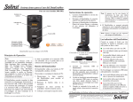
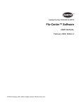
6 Hardware
Figure 6-1 illustrates the Leveloader Gold and the key functions of each component.
ON/OFF
Battery Indicator
24 hr Clock
Display Window
2 Push (Chevron)
Buttons
for Selecting Screen
Options
Push Up/Down Buttons
to scroll through menu
NOTE
Leveloader Gold uses a 9V
battery. If the battery gauge on
the Leveloader is low, replace the
battery with either an alkaline
or lithium. Access the battery by
unscrewing the battery hatch.
USB Connections for
PC Communication
DIN Connector for
RS232 Cable, Optical and
Direct Read Connector
Cables
Figure 6.1 Leveloader Gold
Datalogger
DIN Connector
USB
USB Communications
Cable
Optical
Connector
Direct
Read
Cable
Bottom View showing
Connections
Direct Read
Connector
RS232
Communications
Cable
Figure 6-2 Leveloader Gold Connections
Page 10
Leveloader Gold User Guide
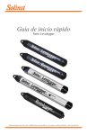
7 Leveloader Gold Menu
22:05
Leveloader Gold Menu
Connect to Logger
View Stored Data
Data to PC
Leveloader Setup
OK
Figure 7-1 Main Menu
Figure 7-1 illustrates the main menu of the Leveloader Gold. The Battery Gauge
depicts the remaining life of the Leveloader’s 9V battery. Battery levels can be
displayed: full, high, medium, low and empty. When the battery icon is empty,
replace the battery immediately.
7.1 Connect to Levelogger
Connect a Levelogger to the Leveloader with the supplied Optical and Direct
Read Connector Cables. A connection can be made directly to a Levelogger
using the Optical Connector, or a Direct Read Cable assembly. Please note that
only one Levelogger should be connected to a Leveloader at a time.
NOTE
The features available within the
Levelogger menu are based on the
type of datalogger connected.
When ‘Connect to Logger’ is selected, the Leveloader will begin to communicate
to the connected datalogger. When communication is successful the Levelogger
Menu will appear. There are six options under the Levelogger menu: ‘Real Time
- View Only’, ‘Data from Levelogger’, ‘Info from Levelogger’, ‘Edit Levelogger’,
‘Load Settings File’ and ‘Restart Levelogger’. Each of these menu options are
described in Section 8.
22:20
Levelogger Menu
Real Time - View Only
Data from Levelogger
Info from Levelogger
Edit Levelogger
Load Settings File
Restart Levelogger
OK
Return
Levelogger Menu
with Levelogger Edge, Junior Edge,
LTC Junior, Rainlogger,
Gold or Junior Connected
22:20
Levelogger Menu
Last Readings
Data from Levelogger
Info from Levelogger
Edit Levelogger
Load Settings File
Restart Levelogger
OK
Return
Levelogger Menu
with Mini LT Connected
(Leveloader Firmware 1.000)
(Leveloader Firmware 2.000 and higher)
Figure 7-2 Levelogger Menu
Page 11
Leveloader Gold User Guide
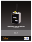
7.2 View Stored Data
‘View Stored Data’ displays a list of stored log files together with the serial
number for each Levelogger file (Figure 7-3). To select a specific log file use the
Up/Down Buttons to highlight the desired log file and select ‘OK’. The next
screen (Figure 7-4) will show the number of readings within the log file and the
complete data set. Use Up/Down Buttons to scroll.
22:10
Log
Log
Log
Log
Log
View Stored Data
ID 1, 1019733
ID 2, 1019755
ID 3, 1018566
ID 4, 1014857
ID 5, 1016321
OK
22:12
View Stored Data
3/200 Readings
Time, cm, Deg C
16:32:25 60.2, 24.78
16:32:27 58.8, 24.75
16:32:29 59.3, 24.77
OK
Menu
Figure 7-3 View Stored Data
Return
Figure 7-4 Next Screen, View Stored Data
Menu
7.3 Data to PC
‘Data to PC’ lists the number of log files stored in the Leveloader (Figure 7-5).
To transfer data from the Leveloader, turn the Leveloader ON, connect the
USB cable from the Leveloader to the PC and open the Levelogger Version 4
(or later) Software. Within the software, select the 'Leveloader' tab (Figure 9-1).
Inside the Leveloader window, click the 'Retrieve Leveloader Settings' icon, then
the download icon to start data transfer from the Leveloader to the PC. To
return to the previous menu, press the right Chevron Button (see Section 9 for
more details).
NOTE
The Leveloader will not turn on
when connected to the PC with
a USB Cable. You must turn the
Leveloader on before connecting,
or unplug from the PC then turn on
and reconnect it.
22:15
Data to PC
3 logs in Leveloader
Ready for data transfer.
Use PC Software
Connect to PC
Figure 7-5 Data to PC Menu
Page 12
Leveloader Gold User Guide
7.4 Leveloader Setup
The Leveloader Setup menu (Figure 7-6) contains five functions: Time Setup,
Restored Factory Settings, Contrast Control, Leveloader Information and Erase
Most Recent Log.
22:17
Leveloader Setup
Time Setup
Restore Factory Settings
Contrast Control
Leveloader Information
Erase Most Recent Log
OK
Menu
Figure 7-6 Leveloader Setup Menu
7.4.1 Time Setup
NOTE
The Leveloader Time can also
be updated automatically by
synchronizing with a PC using
Levelogger Software. Refer to
Section 9.3 for further detail.
The Time Setup menu is used to adjust the date and time settings of the
Leveloader (Figure 7-7). The date/time format is YY/MM/DD HH:MM:SS.
Using the Up/Down buttons, scroll and change the date/time, then select
{SUBMIT} to confirm the changes. To discard the changes, click ‘Menu’ which
also returns to the previous menu.
22:31
Edit Time Setup
05/02/07 16:45:08
{YY/MM/DD HH:MM:SS}
0123456789
{PREV} {NXT} {SUBMIT}
OK
Cancel
Figure 7-7 Time Setup Menu
7.4.2 Restore Factory Settings
This menu is used to restore the default settings of the Leveloader to the original
factory settings. E.g. Contrast Control.
7.4.3 Contrast Control
Contrast Control is used to adjust the brightness of the LCD. The user can also
adjust the contrast for the LCD in the main menu by holding down the top right
Chevron Button and selecting either the Up or Down Button.
7.4.4 Leveloader Information
Leveloader Information shows the firmware version number, memory capacity,
percent available and Solinst website address.
7.4.5 Erase Most Recent Log
Erase Most Recent Log function will delete the latest log file stored in the
Leveloader, to free up memory. When selected, a warning message will prompt
the user to confirm the removal of the log file. To erase all files stored in the
Leveloader use the Levelogger PC Software. (See Section 9.2.)
Page 13
Leveloader Gold User Guide
8 Levelogger Menu
NOTE
The features available within the
Levelogger Menu are based on the
type of datalogger connected.
When ‘Connect to Logger’ is selected, the Leveloader will begin to communicate
with the connected datalogger. When communication is successful the Levelogger
Menu will appear (Figure 8-1). There are six options available: ‘Real Time - View
Only’, ‘Data from Levelogger’, ‘Info from Levelogger’, ‘Edit Levelogger’, ‘Load
Default Settings’ and ‘Restart Levelogger’.
22:20
Levelogger Menu
Real Time - View Only
Data from Levelogger
Info from Levelogger
Edit Levelogger
Load Settings File
Restart Levelogger
OK
Return
Figure 8-1 Levelogger Menu
NOTE
If a Mini LT or Black LTC Levelogger
are connected, the ‘Real Time View
Only’ function will be replaced by
‘Last Readings’. This function will
allow the user to only view the
last data points recorded by the
attached Levelogger
8.1 Real Time - View Only
When ‘Real Time - View Only’ is selected from the Levelogger Menu, the
Levelogger will take a reading immediately and display it in the LCD screen
(Figure 8-2). The display will show the data logger serial number, available
memory and the readings from the data logger’s available channels (level,
temperature and/or conductivity).
22:20
Last Readings #65269
Free Mem 24000Readings
LEVEL
64.7cm
TEMPERA 23.90Deg C
Real Time ON
22:21
Real Time - View Only
Free Mem: 40000Readings
23.90Deg C
105.77 cm
Real Time - View Only
Second (s) 01
{SUBMIT}
Menu
Last Readings Menu (Silver LT)
Real Time ON
Menu
Figure 8-2 Real Time - View Only
22:22
Last Readings
Second (s) 01
{SUBMIT}
OK
22:22
OK
Menu
Figure 8-3 Real Time - Edit Menu
To update the Levelogger readings periodically, select ‘Real Time On’ using the
left Chevron Button. When enabled, input a sampling rate (Figure 8-3). Select
the time increments: seconds, minutes or hours and then the rate: 1-99. Real
Time readings can not be saved.
Menu
Last Readings Edit Menu (Silver LT)
Page 14
Leveloader Gold User Guide
8.2 Data from Levelogger
‘Data from Levelogger’ downloads the stored data from the attached Levelogger.
The screen (Figure 8-4) allows scrolling with the Up/Down buttons through the
stored data, indicates battery level, time, data logger serial number and number
of readings. To save the data to the Leveloader, push the left Chevron Button.
After the data has been saved in the Leveloader memory, the Leveloader will
return to the main menu.
22:23
#1019694 Bat 100%
3/200 Readings
Time, cm, Deg C
16:32:25 60.2, 24.78
16:32:27 58.8, 24.75
16:32:29 69.3, 24.77
Save Log
Menu
Figure 8-4 Data from Levelogger Menu
8.3 Info from Levelogger
When ‘Info from Levelogger’ is selected, a list of the information from the
attached Levelogger will be shown on the screen. The list contains the firmware
version, battery level, number of readings, data logger date, time and data logger
status.
NOTE
The Levelogger must be stopped
in order to change the settings.
To stop the Levelogger, press
BOTH the UP and DOWN Buttons
simultaneously.
Remember to save the log before
re-starting.
8.4 Edit Levelogger
The ‘Edit Levelogger Menu’ displays the attached data logger’s settings. The
Leveloader can adjust many of the Levelogger’s settings, including: Date/Time,
Project ID, Location, Sampling Rate, Sampling Type, Units, and Altitude for
some datalogger types. To adjust any setting, highlight it and click the Edit button.
8.4.1 Edit Date/Time
This menu item is used to synchronize the date and time of the Levelogger with
the Leveloader. To synchronize the time, highlight the Date/Time and click
‘Edit’ in the Edit Levelogger menu.
NOTE
I If there was a password set for
the Leveloader, it will need to be
entered before you can edit the
Levelogger settings. See Section 8.7
for details.
22:24
Edit #1019694
Time (sync to loader)
26/09/2011, 10:24:02
Project ID:
Testing
Location:
Edit
Menu
Figure 8-5 Edit Levelogger Menu
Page 15
Leveloader Gold User Guide
8.4.2 Edit Project ID and Location
Figure 8-6 shows the ‘Edit Project ID’ screen. The current Project ID is shown
on top of the menu as ‘TESTING’. To change the Project ID, highlight the
character to modify by selecting {PREV} or {NXT}. Select a character from the
list below and click ‘Edit’ to modify the highlighted character.
22:25
Edit Project ID:
TESTING
ABCDEFGHIJKLMNOPQRST
UVWXYZ0123456789+-:
{PREV} {NXT} {SUBMIT}
OK
Cancel
Figure 8-6 Edit Project ID Menu
Shading over the character indicates the current character. Press {SUBMIT}
when complete. The Leveloader will send the new setting to the Levelogger. To
discard the changes, click the ‘Cancel’ button before submitting. This will return
you to the Edit Levelogger menu and discard the changes. This type of operation
is also used to modify the Location.
8.4.3 Edit Sampling Rate and Sampling Type
The ‘Edit Sampling Rate’ screen displays the current sampling rate stored in the
Levelogger (Figure 8-7). The following procedure is used to modify the sampling
rate:
NOTE
In ‘Event Based’ sampling, the user
must define what the pressure
change must be for data logging
to occur, as well as define the
sampling rate to determine how
often the data logger checks
pressure changes.
1. Select unit (Seconds, Minutes and Hours) using UP/DN and click Edit.
2. Select duration (1 – 99) using UP/DN and click OK.
3. When {SUBMIT} is highlighted, click OK to confirm all the changes
and the new setting will be sent to the Levelogger.
To cancel the operation, click ‘Cancel’ to return to the Edit Levelogger menu.
These changes can be confirmed by viewing the ‘Edit Levelogger Menu’. The
‘Edit Sampling Type’ screen displays the current sampling type stored in the
Levelogger (Figure 8-8). Use the up/down buttons to scroll through the sampling
types: Linear, Schedule or Event Based. To accept the selection press {Submit}.
22:27
22:26
Edit Sampling Rate:
Second(s)
Linear
05
{SUBMIT}
{SUBMIT}
OK
Edit Sampling Type:
Cancel
Figure 8-7 Edit Sampling Rate Menu
OK
Cancel
Figure 8-8 Edit Sampling Type Menu
Page 16
Leveloader Gold User Guide
8.4.4 Edit Unit
‘Edit Unit’ (Figure 8-9) allows you to change the units that the Levelogger is
using to record LEVEL and TEMPERATURE. Use the Up/Down buttons to
scroll through the units for LEVEL, and press okay when the desired unit is
shown. Repeat this for the TEMPERATURE unit.
22:28
Edit Unit:
LEVEL:
TEMP:
m
C
OK
Cancel
Figure 8-9 Edit Unit Menu
NOTE
Edit Altitude is only available for the
Levelogger Gold and Junior Models.
Levelogger Edge and Levelogger
Junior Edge data can be adjusted
for Altitude post data collection
using the Data Compensation
Wizard. See Levelogger User Guide.
8.4.5 Edit Altitude
‘Edit Altitude’ is very similar in setup to the Edit Project ID operation. The
Leveloader only allows the numerical value of the altitude to be modified, not
the units. Enter the altitude and select {SUBMIT} to confirm the modification.
The units of altitude can only be adjusted using Levelogger Software on a PC.
8.5 Load Levelogger Settings Files
NOTE
Maximum altitude value for the
Levelogger Gold is 5000 m
(16400 ft).
The maximum altitude value for
the Mini LT Leveloggers is 3000 m
(9750 ft).
To use this feature, the ‘Levelogger Settings Files’ must be pre-programmed
using Levelogger PC Software. Details provided in section 9.1.
Once selected, a list of up to 10 customizable settings are shown (Figure 8-10).
By using the Up/Down buttons, the user can select one of the settings and send
it directly to the attached Levelogger. A confirmation message will follow. Then
scroll down to restart the Levelogger
22:29
Load Settings Files
File 1 PumpTest
File 2 SlugTest
File 3 StepTest
File 4 Monitor1
File 5 Monitor2
OK
Menu
Figure 8-10 Load Settings Files Menu
Page 17
Leveloader Gold User Guide
NOTE
Remember the Levelogger must be
stopped to be restarted. To stop the
Levelogger, press BOTH the UP and
DOWN Buttons simultaneously.
8.6 Restart Levelogger
By selecting ‘Restart Levelogger’ the user can start data logging immediately or
with a defined future start time (Figure 8-11). If a future start time is selected
the user must enter the desired start time (Figure 8-12). Please note that if
the Levelogger is already running, then it must first be stopped (Figure 8-13).
Remember to save the data file before restarting the Levelogger.
22:30
Restart Levelogger
#1019694
Start Logging
Future Start Logging
NOTE
Remember to save the log file
before restarting the Levelogger.
Select
22:31
Edit Future Start Time
05/02/07 16:45:08
{YY/MM/DD HH:MM:SS}
0123456789 {Next hour}
{PREV} {NXT} {SUBMIT}
OK
Cancel
Figure 8-11 Levelogger Restart Options
Cancel
Figure 8-12 Edit Future Start Time
22:32
Restart Levelogger
#1019694
Press both UP/DN to
stop the logger
Menu
Figure 8-13 Stopping Levelogger
8.7 Security
NOTE
Remember that the Levelogger
must be stopped to edit settings.
If the Leveloader Gold has been configured with a password (see section 9.4
for details), then an Enter Password screen will appear if the user attempts to
edit the attached Levelogger (Figure 8-14). If password protection is activated,
use the UP/DN buttons to choose letter/function. Press OK to enter each letter
in the password. Use {PREV} and {NXT} to move the cursor in the password
and {SUBMIT} when the password is complete. Click the Menu button to exit
the Enter Password screen. Note that the Levelogger must be stopped to edit
settings.
23:33
Enter Password
ABCDEFGHIJKLMNOPQRST
UVWXYZ0123456789.:/+
{PREV} {NXT} {SUBMIT}
OK
Menu
Figure 8-14 Enter Password Menu
Page 18
Leveloader Gold User Guide
NOTE
Remember that the Leveloader
must be in the ‘Data to PC’ mode
when connecting to the software.
NOTE
9 Levelogger Software and Leveloader Gold
Figure 9-1 shows the main window of Levelogger Software Version 4.0.3.
To access the Leveloader options from the software window, click on the
‘Leveloader’ tab.
To begin communication between the Leveloader and the PC, turn the Leveloader
on and connect the Leveloader using either the supplied USB or RS232 cable.
Select the proper communications port that the Leveloader is connected to
using the drop down ‘Com Port’ selection window. Select the ‘Data to PC’
option from the Leveloader main menu. Click the 'Retrieve Leveloader Settings'
icon
in the software.
Please note that depending on
the computer make, the USB
connection must sometimes
be made before starting the
Levelogger Software.
NOTE
The Leveloader will not turn on
when connected to the PC with
a USB Cable. You must turn the
Leveloader on before connecting,
or unplug from the PC then turn on
and reconnect it.
Figure 9-1 Leveloader Tab
Software and Firmware Updates
NOTE
The 'Leveloader Information'
section of the Leveloader Tab will
display the firmware version that
the Leveloader is currently using.
The software automatically checks for updates each time it is opened. If there
is an update, "Software Update Available" will appear in the top right of the
menu bar. When you click the message, a webpage will open, allowing you to
download the update.
The Software checks for firmware updates once you have connected the
Leveloader to the PC, put it in 'Data to PC' mode and communicated with
the Software. "Firmware Update Available" will appear in the top right corner.
When you click the message, a webpage will open, allowing you to download the
update. See Section 10 for firmware update instructions.
Page 19
Leveloader Gold User Guide
NOTE
By selecting ,
you can
choose the
information you want to include in
the file names of your downloaded
data, e.g. start time, stop time,
location and serial number.
When the Leveloader Gold is connected to the PC, the window on the left of
the Leveloader tab will display the log files that are available for download. To
download data from the Leveloader, select the file(s), then click the download
data icon
.
A destination folder window will open where you can choose the location your
log files will be saved. Click the ‘OK’ button to start the transfer process.
Figure 9-2 Log File Download
Page 20
Leveloader Gold User Guide
NOTE
For more information on the 'Data
Control' tab, see the Levelogger
Series User Guide for Software
Version 4 (or later).
To view the log files, open the 'Data Control' tab. You can open the files using
the open file icon
. From here, you can also print data or export data to
a .csv or .xml file.
Figure 9-3 Data Control Window
Page 21
Leveloader Gold User Guide
NOTE
Remember that the Leveloader
must be in the ‘Data to PC’ mode.
9.1 Customizable Levelogger Settings File Setup
This feature allows you to input up to 10 customized files with pre-defined
settings for the Levelogger series including: Project ID, Location, Sample Mode,
Sample Rate, Channel ID, Units and Offset.
To create a settings file in the 'Leveloader' tab, select the type of Levelogger
you are creating the file for from the drop-down menu, then enter the desired
Levelogger settings file name. The available sampling options will be displayed
for that Levelogger type. Enter the settings to create the customized file
(Figure 9-4). To send the settings file to the Leveloader, click the 'Apply Leveloader
Settings' icon
.
NOTE
Altitude and Density can be set
for the Levelogger Junior, LTC
Levelogger Junior, and Levelogger
Gold and Barologger Gold
dataloggers.
Figure 9-4 Levelogger Default File Settings
Page 22
Leveloader Gold User Guide
Please note that inputs into the ‘Settings Title’ will appear as the settings file title
in the Leveloader (Figure 9-6). To create and add more than one customizable
file, select a new ‘EMPTY’ slot from the drop down menu (highlighted drop
down menu below).
Figure 9-5 Levelogger Settings File - Setup
22:29
Load Settings Files
File 1 PumpTest
File 2 SlugTest
File 3 StepTest
File 4 Monitor1
File 5 Monitor2
OK
Menu
Figure 9-6 Leveloader - Load Settings File Window
Page 23
Leveloader Gold User Guide
9.2 Erase Data
To erase the stored files on the Leveloader Gold, click on the erase icon
located in the 'Leveloader' tab. A message will prompt the user that all of the
data will be erased. Once the data is erased, the attached Leveloader will indicate
that there are 0 logs stored.
9.3 Clock Synchronization
The attached Leveloader’s system time is displayed in the bottom left corner of
the 'Leveloader' tab. To synchronize the Leveloader to the PC clock, simply click
‘Synchronize’.
Figure 9-7 Clock Synchronization
Page 24
Leveloader Gold User Guide
NOTE
A maximum of 6 characters can be
entered for the password.
9.4 Password Setup
Activating the password protection function will prevent unauthorized changes
using the Leveloader, to an attached Levelogger's settings.
In this section of the 'Leveloader' tab, check to enable password protection, enter
your password, then re-enter to confirm (Figure 9-8). To send the password to
.
the Leveloader, click the 'Apply Leveloader Settings' icon
Figure 9-8 Password Setup
Once a password has been set, the 'Password Setup' section will update to look
like Figure 9-9.
Figure 9-9 Password Enabled
To remove a password, enter the current password, uncheck 'Enable Password
Protection on Edit Levelogger', then click the 'Apply Leveloader Settings' icon.
. The 'Password Setup' section will update to look like Figure 9-10.
Figure 9-10 Password Not Enabled
Page 25
Leveloader Gold User Guide
NOTE
Before proceeding with a firmware
upgrade, ensure your Leveloader
is using a new/fully charged 9V
battery. Using a depleted battery
may cause communication
interruption.
DO NOT allow an interruption to
communication between the PC
and Leveloader during a firmware
upgrade. It is important that
the communication between
the PC and the Leveloader is not
interrupted during a firmware/
calibration upload.
PLEASE make sure to close any
other running programs, especially
screen savers, and DO NOT
disconnect the Leveloader before
the upload is finished.
NOTE
The Software checks for firmware
updates once you have connected
the Leveloader to the PC, put
it in 'Data to PC' mode and
communicated with the Software.
"Firmware Update Available" will
appear in the top right of the menu
bar. When you click the message, a
webpage will open, allowing you to
download the update.
10 Firmware Upgrade Utility
The Firmware Upgrade Utility is included with the Levelogger PC Software
and can be used to upload new firmware files into a Leveloader. The firmware
file can be obtained from http://www.solinst.com/Downloads/
To upload new firmware to a Leveloader Gold, follow these steps:
1) Turn the Leveloader ON, scroll to the ‘Data to PC’ option on the
Leveloader Menu and select ‘OK’. Connect the Leveloader to the PC using
the USB or RS232 Communication Cable.
2) Open the Solinst Firmware Update Utility, which is located in the ‘Utility’
folder in the Levelogger4_0 folder. It can also be launched from the
Utilities menu in the Levelogger Software. Pick the Com Port that the
Leveloader is connected to and make sure the Baud Rate is set to 115200.
3) Click the ‘Open’
button, which should open a file dialog asking for
the firmware file (*.ssf) to upload. Navigate to where the firmware file was
saved on your PC, then click on the file and click ‘Open’ (make sure you
have unzipped the downloaded firmware *.ssf file).
4) Check the ‘Firmware File Information’ box to make sure that the opened
file is the right one.
5) Click the ‘Upload Firmware’
process.
button to start the firmware upload
6) If a communication error occurs and is indicated in the Leveloader
Information Window either before the “Verified Program Checksum”
message or after the “Program Information Section”, then restart the
upgrade process.
Figure 10-1 Firmware Upgrade Utility Window
Page 26