1
HSL-WISVCUP
Ragsdale Bodymaker
Servo Cupfeed Control
User's Manual
Systems Engineering Associates, Inc.
14989 West 69th Avenue
Arvada, Colorado 80007 U.S.A.
Telephone: (303) 421-0484
Fax: (303) 421-8108
www.sea-seg.com
01/2004
HSL-WISVCUP
Ragsdale Bodymaker
Servo Cupfeed Control
User's Manual
Copyright © 2001 Systems Engineering Associates, Inc.
All Rights Reserved!
Revised: 27 January 2004
WARNING
To ensure that the equipment described by this User Manual, as well as the equipment
connected to and used with it, operates satisfactorily and safely, all applicable local and national
codes that apply to installing and operating the equipment must be followed. This includes the
National Electrical Code in the USA and other applicable legislation, regulations, and codes in
practice elsewhere. Since codes can vary geographically and can change with time, it is the
user’s responsibility to determine which standards and codes apply, and to comply with them.
FAILURE TO COMPLY WITH APPLICABLE CODES AND STANDARDS CAN RESULT IN
DAMAGE TO EQUIPMENT AND/OR SERIOUS INJURY TO PERSONNEL.
Persons supervising and performing installation or maintenance must be suitably qualified and
competent in these duties, and should carefully study the User Manual and any other manuals
referred to by it prior to installation and/or operation of the equipment.
The manufacturer accepts no liability for any consequences resulting from inappropriate,
negligent or incorrect installation, operation, or adjustment of the equipment.
The contents of the User Manual are believed to be correct at the time of printing; however, no
responsibility is assumed for inaccuracies. In the interests of a commitment to a policy of
continuous development and improvement, the manufacturer reserves the right to change the
specification of the product or it’s performance or the contents of the User Manual without notice.
Copyright © 2001 Systems Engineering Associates, Inc.
All rights reserved!
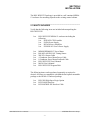
CONTENTS
1. General Description
1.1
1.2
1.3
1.4
1.5
1.6
1.7
1
Features
Functional Description
Cupfeed Cam Servo Motor Control
Alarm Detection
Interlocks to Existing Control System
Interlocks from Existing Control System
Optional High Speed Logic
2. Installation
2.1
2.2
2.3
2.4
2.5
2.6
1
2
2
3
4
4
5
7
What's Included
Power Required
Mounting the HSL-WISVCUP
Wiring the HSL-WISVCUP
Mounting the RSV34-MS1 Resolver
HSL-WISVCUP Software Installation
2.6.1 Windows Based Setup Program Installation
2.6.2 DOS Based Setup Program Installation
2.6.3 SYSdev Program Development Software
Installation
2.6.4 Application Program Installation
7
8
8
8
10
11
11
12
Modify Existing PLC Program
Power Up HSL-WISVCUP
HSL-WISVCUP Set-Up
2.9.1 Default Set-Up Variables
2.9.2 Verify Servo Cupfeed Set-Up Parameters
2.9.3 Verify Main Crank Resolver
2.9.4 Set Main Crank Zero
2.9.5 Verify Cupfeed Cam Resolver
2.9.6 Time Cupfeed Cam to Main Crank
2.9.7 Verify Cupfeed Tracking
2.9.8 Verify Machine Operation
14
15
17
17
18
18
18
19
19
21
21
2.10 Module/Servo Amplifier Installation/Replacement
2.10.1 M4510 Module Installation
2.10.2 P4500 Power Supply Installation
2.10.3 B25A20 Servo Amplifier Installation
2.10.4 Download HSLSCUP Program and Set-Up Data
to M4510
2.10.5 Download SRVCUPR Program and Set-Up Data
to S4520-RDC in Slot01
23
23
25
26
2.7
2.8
2.9
HSL-WISVCUP User’s Manual
13
13
27
28
SYSTEMS Electronics Group
-i-
CONTENTS
3. Tuning the Servo Loop
3.1
3.2
3.3
3.4
3.5
29
Description of PID Servo Loop
Proportional (P) Gain
Integral (I) Gain
Derivative (D) Gain
Tuning the Servo Motor with Machine Running
4. WISVCUP - Windows Based
Set-up Program Reference
29
30
31
32
33
35
4.1
4.2
General Description
The File Menu
4.2.1 The Set-Up Data File
4.2.2 Upload (save) Data
4.2.3 Download Program
4.2.4 Download (restore) Data
4.2.5 Print Report
36
37
38
39
40
42
43
4.3
The Edit Menu
4.3.1 Enable Offline Editing
4.3.2 Set-Up Comm Port
4.3.3 Edit Set-Up Passcode
44
44
45
46
4.4
The View Menu
4.4.1 Target Board Interface
4.4.2 View Online Data
4.4.3 View Offline Data
47
49
49
49
4.5
The Bodymaker Menu
4.5.1 Main Display Window
4.5.2 Set-Up Parameters Window
4.5.3 Machine Timing Window
4.5.4 Shift Data Window
4.5.5 I/O States Window
50
51
52
54
57
59
4.6
The Servo Cupfeed Menu
4.6.1 Set-Up Parameters Window
4.6.2 Tuning Window
4.6.3 Diagnostics Window
4.6.4 Acquire Data Signatures Window
60
61
62
65
67
HSL-WISVCUP User’s Manual
SYSTEMS Electronics Group
- ii -
CONTENTS
5. HSLSCUP - DOS Based
Set-up Program Reference
71
5.1
Main Menu
1: Bodymaker/Trimmer Set-up (M4510 Prog Port)
2: Cupfeed Set-up (S4520 Slot-01 Motion Port)
3: Select Bodymaker (B/M number) to Set-up
71
72
72
73
5.2
Bodymaker/Trimmer Set-up Main Menu
4: Download Program to M4510
73
74
75
76
78
80
83
84
85
5.3 Cupfeed Set-up Main Menu
1: Set Cupfeed Set-up Parameters
2: Time Cupfeed/Position Diagnostics
3: Tune Cupfeed Servo Motor
4: Download Cupfeed Program to S4520
5: Download Cupfeed Set-up Data to S4520
6: Upload (Save) Cupfeed Set-up Data from S4520
6. Recommended Spare Parts
87
7. Trouble-shooting
89
7.1
7.2
7.3
7.4
Cups do not load properly
Cupfeed Cam only turns slowly when Machine
is stroked
Cupfeed Cam does not move
Cupfeed Cam does not track properly
89
89
90
97
LIST OF FIGURES
Figure 1 - Cupfeed Motor Conduit Routing
Figure 2 - M4510 Configuration
Figure 3 - Location of Ram at "Cupfeed Time" Position
Figure 4 - Location of Cupfeed Cam at "Cupfeed Time" Position
Figure 5 - S4520 and S4568 Dip Switch Settings
Figure 6 - S4520 Motion Controller Pin-outs
9
16
19
20
23
34
APPENDICES
Existing PLC Program Modifications Example
Drawings
HSL-WISVCUP User’s Manual
Appendix A
Appendix B
SYSTEMS Electronics Group
- iii -
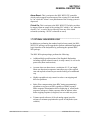
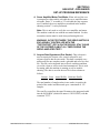
SECTION 1
GENERAL DESCRIPTION
This section describes the features of the HSL-WISVCUP Servo
Cupfeed control package. This includes the functional description,
alarms detected, interlocks between the control package and the
existing control system, etc.
________________________________________________________
1.1 FEATURES
•
Provides Servo motor driven positive cupfeed cam control for
APM Positive cupfeed cam upgrade.
•
Interfaces directly with cupfeed cam servo motor, machine
mounted main crank resolver, and existing control system to
accurately cam cupfeed with main crank in all modes and all
speeds.
•
Immediate cupfeed cam stop at detection of short can or tear-off
protects valuable tooling by preventing the feeding of an
additional cup.
•
Completely automatic synchronization of cupfeed cam with main
crank shaft when clutch is engaged to reduce down-time and
reduce operator manual interaction.
•
Optional high speed logic functions add-on performs additional
high speed control functions of Ragsdale Bodymaker including
cupfeed solenoid control, air strip control, as well as die
protection (short can detection).
•
Alarm detection: cupfeed following fault, cupfeed servo motor
o'temp, cupfeed motor amplifier fault.
•
Provided with Windows and DOS based set-up software
packages. This allows all user selectable parameters to be set
using easy to use menus as well as download the respective
application programs and set-up data.
•
Based on the high performance M4510 PLC/PLS/Motion control
module. This allows easy trouble-shooting and user customization
using SYSdev (DOS-based) programming package.
HSL-WISVCUP User’s Manual
SYSTEMS Electronics Group
-1-
SECTION 1
GENERAL DESRIPTION
________________________________________________________
1.2 FUNCTIONAL DESCRIPTION
The HSL-WISVCUP Bodymaker servo cupfeed control package is an
electronic upgrade package used in conjunction with the Ragsdale
servo positive cupfeed upgrade. It provides complete motion control
of the servo cupfeed cam plus detection of the following alarms:
cupfeed motor over temp, amplifier fault and cupfeed cam following
fault.
The package interfaces directly to the machine mounted cupfeed
servo motor, cupfeed timing sensor, main crank resolver, as well as
the host PLC via discrete DC I/O.
The control system is not a dedicated "black box", but is instead
implemented using the high performance SYSTEMS M4510
PLC/PLS Motion control module. This allows easy customization by
either SEA or the end user. The M4510 module is programmed using
the DOS-based SYSdev programming package. This allows the
module to be programmed in any combination of Ladder or Highlevel (subset of "C"), as well as perform on-line monitoring and
trouble-shooting.
________________________________________________________
1.3 CUPFEED CAM SERVO MOTOR CONTROL
The cupfeed cam motor control is implemented with a high speed
(0.5msec update) PID servo loop. The main crank position is used as
the reference for the servo loop with the cupfeed cam position used as
the feedback. Both main crank position and cupfeed cam positions are
generated with resolvers to provide the highest degree of reliability
and noise immunity. Both resolver format signals are converted to
digital with a resolution of 12-bits (0-4095). The PID servo loop nulls
the error (difference) between the main crank and cupfeed positions to
zero (or as minimal as is practical). Full access to the PID gains
allows the servo loop to be tuned to provide the optimum balance
between acceptable error and minimum running current.
At the detection of a short can or tear-off, the cupfeed cam is
immediately stopped to prevent the feeding of an additional cup
which protects valuable tooling. The cupfeed cam automatically
synchronizes with the main crank when the machine is re-started to
minimize down-time and eliminate manual timing by the operator.
HSL-WISVCUP User’s Manual
SYSTEMS Electronics Group
-2-
SECTION 1
GENERAL DESCRIPTION
The cupfeed cam is activated by the clutch solenoid control of the
existing control system. The "HSL-WISVCUP" is interlocked to the
existing clutch solenoids via redundant positively guided relays with
self-check to maximize safety. The cupfeed servo motor is enabled
via a contactor driven by these relays and thus incorporates the same
level of safety typically provided with dual clutch solenoids with
hardware interlocks.
________________________________________________________
1.4 ALARM DETECTION
The package detects the following alarms:
Cupfeed Following Fault: This alarm occurs when the cupfeed
cam following error (difference between main crank position and
cupfeed cam position) exceeds a user defined preset. This indicates
either binding in the cupfeed cam, miss-tuning of the PID gains,
broken belt, etc.
Cupfeed Amplifier Fault: This fault is generated by the B25A20
Cupfeed amplifier directly. Sources of this fault include: amplifier
output short circuit, amplifier over-voltage, amplifier over
temperature.
Cupfeed Motor Over Temp: Activated by the thermostat in the
cupfeed servo motor. This fault occurs when the temperature of the
motor exceeds 155° C.
The above alarms are available to the host PLC via discrete outputs.
These should be used to stop the machine and indicate the problem
when any one of the alarms occurs. In addition, the alarms are
summed into the "Machine Run Enable" output which is available to
the host PLC via a discrete output. This should be used to stop the
machine when any one of the alarms occurs.
HSL-WISVCUP User’s Manual
SYSTEMS Electronics Group
-3-
SECTION 1
GENERAL DESRIPTION
________________________________________________________
1.5 INTERLOCKS TO EXISTING CONTROL SYSTEM
In addition to the alarms listed in section 1.4, the following interlocks
are +24VDC Discrete signals which should be interlocked to the
existing control system:
Machine Run Enable: This signal is the summation of all the
alarms in section 1.4. When "ON", all alarms are clear and the
machine is enabled to stroke. When "off", one or more of the alarms
is active and the machine must be stopped and disabled from running.
Cupfeed Enable: This signal indicates to the existing system when
the cupfeed is synchronized with the main crank and thus, if the
existing system is ready, cups can be feed into the machine. This
signal typical turns "on" within one stroke after the clutch is engaged
in continuous or inch mode when the cupfeed has synchronized with
the main crank and stays "on" until a short can is detected or the
cupfeed cam is manually moved out of time with the crank.
________________________________________________________
1.6 INTERLOCKS FROM EXISTING CONTROL SYSTEM
The following interlocks must be provided by the existing control
system:
Run Mode (Wire 544): This is an input to the HSL-WISVCUP
controller which should be on when "Cont." or "Inch" mode is
selected. This can be mapped from an output of the existing PLC. See
the suggested existing PLC ladder logic in Appendix A.
Run Mode (Wire 526): This is a hardware interlock which must be
derived directly from the RUN/BAR selector switch of the existing
system. This interlock disables the cupfeed servo motor contactor
when in BAR mode and thus provides the function of safety interlock
when bar mode is selected.
Short Can Alarm: This is an input to the HSL-WISVCUP which
should be mapped from an output of the existing PLC and should be
"on" when a short can is detected by the existing PLC. This input
stops the cupfeed cam immediately and prevents another cup from
being fed into the machine.
HSL-WISVCUP User’s Manual
SYSTEMS Electronics Group
-4-
SECTION 1
GENERAL DESCRIPTION
Alarm Reset: This is an input to the HSL-WISVCUP controller
which can be mapped from an output of the existing PLC and should
be "on" while the "Alarm" reset push-button of the existing system is
depressed.
Clutch On: This is an input to the HSL-WISVCUP which can either
be mapped from an output of the existing PLC which is "on" when the
clutch is "on", or can be derived directly from one of the clutch
solenoids (assuming +24VDC solenoids are used).
________________________________________________________
1.7 OPTIONAL HIGH SPEED LOGIC
In addition to performing the standard cupfeed cam control, the HSLWISVCUP package can be upgraded to perform additional high speed
logic functions of the bodymaker by purchasing the optional HSLWI6 package.
The HSL-WI6 option package performs the following:
•
Additional high speed functions of the Ragsdale Bodymaker
including cupfeed solenoid control, air strip control, as well as die
protection (short can detection)
•
Accurate short can detection to a resolution of 1/4" can length.
Short can detection incorporates immediate stop of the cupfeed
cam and cupfeed solenoid to prevent the feeding of an additional
cup.
•
Highly repeatable air strip control to reduce can stripping and
blow-out problems.
•
Brake Wear compensation (Auto BDC timing programming)
algorithm to stop press at BDC regardless of brake response.
Brake response determination allows displaying of actual brake
response (in degrees). Brake response alarm to indicate when
brake stopping response (in degrees) has exceeded user preset.
•
Trimmer speed reference (0-10volt analog output) provides
reference to trimmer proportional to speed of bodymaker (user
scalable).
HSL-WISVCUP User’s Manual
SYSTEMS Electronics Group
-5-
SECTION 1
GENERAL DESRIPTION
•
Data Acquisition: Total number of good cans produced and total
number of short can faults (for both the current shift and last
shift).
•
Built-in 2 Line X 40 character sealed display with 24 key
membrane keypad allows local viewing of collected data (good
can count, short can count, brake response) by operator and set-up
of some user variables (passcode protected) by authorized
personnel.
•
Built-in PLS provides all machine timing, eliminating need for
additional PLS.
The HSL-WI6 consists of an additional I/O board which is added to
the M4510 module, pre-wired field wiring arm for the I/O board,
D4591 Keypad/Display, HSL-WI6 User manual, and the high speed
logic program "HSLSCUP6" which is loaded into the main processor
of the M4510 (replacing the "HSLSCUP" program).
The HSL-WI6 option package can be used to enhance the
performance of the APM Bodymaker or to reduce the program
modifications required to the existing PLC when upgrading a standard
from a standard cupfeed to the positive cupfeed.
HSL-WISVCUP User’s Manual
SYSTEMS Electronics Group
-6-
SECTION 2
INSTALLATION
The HSL-WISVCUP package is provided in a self contained NEMA
12 enclosure for mounting adjacent to the existing control cabinet.
________________________________________________________
2.1 WHAT'S INCLUDED
Verify that the following items are included when unpacking the
HSL-WISVCUP:
1ea.
HSL-WISVCUP NEMA 12 enclosure including the
following:
1ea. M4510 PLC/PLS module
1ea. P4500 Power Supply
1ea. B25A20 Servo Amplifier
1ea. PS300W-96V Servo Power Supply
1ea.
1ea.
1ea.
1ea.
1ea.
1ea.
1ea.
1ea.
MPM892FRMM-B 3" Servo Motor
Bi4-M12-AP6X-H1141 Timing Sensor
WK 4T-6 Sensor Cable
4-Conductor Servo Motor Power Cable
8-Conductor Servo Motor Feedback Cable
HSL-WISVCUP User's Manual
M4510 User's Manual
HSL-WISVCUP Program Disk
The following items can be purchased separately as required or
desired. All items are compatible with both the back-panel mountable
package or the NEMA 12 enclosed package:
1ea.
1ea.
1ea.
HSL-WI6 High Speed Logic Option
RSV34-MS1 Resolver
RSV-RSCBLE-XX Resolver Cable
HSL-WISVCUP User’s Manual
SYSTEMS Electronics Group
-7-
SECTION 2
INSTALLATION
________________________________________________________
2.2 POWER REQUIRED
The HSL-WISVCUP is powered from 115VAC 50/60HZ and
+24VDC. The 115VAC is used to power the M4510 module and
B25A20 Cupfeed Servo amplifier while the +24VDC is used to power
the +24VDC I/O (sensors, discrete interlocks, etc.). Current required
from the 115VAC line is 2.5 Amps (with a 6 Amp peak at power up).
Current requirements from the +24VDC power source is less than 0.5
Amps.
The input power should be derived from the existing control system
(or at least interlocked with the existing control system) such that
when the main disconnect of the existing control system is turned
"off", all power to the HSL-WISVCUP is also turned "off".
________________________________________________________
2.3 MOUNTING THE HSL-WISVCUP
Mount the HSL-WISVCUP NEMA 12 enclosure in proximity to the
existing control cabinet. Mount the MPM892FRMM-B cupfeed servo
motor on the mounting bracket supplied with the mechanical portion
of the Ragsdale servo cupfeed upgrade package. Mount the Bi4-M12AP6X-H1141 timing sensor on the mounting bracket supplied with
the mechanical portion of the servo cupfeed upgrade package.
________________________________________________________
2.4 WIRING THE HSL-WISVCUP
Referring to the electrical control schematic at the back of this
manual, wire the HSL-WISVCUP as follows:
1) Incoming Power (115VAC - Wires 803, 801, 900 and +24VDC Wires 501 and 500)
2) Interlocks between existing control system and HSL-WISVCUP
(Wires 544, 545, 546, 547, 550-557, FLT1, and FLT2)
3) Clutch interlock wiring (Wires 512, 513, 518, 519, and 526)
4) Cupfeed timing sensor (Wires 510, 501, and 500)
HSL-WISVCUP User’s Manual
SYSTEMS Electronics Group
-8-
SECTION 2
INSTALLATION
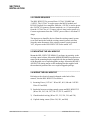
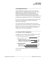
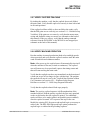
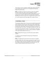
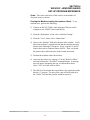
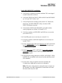
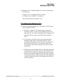
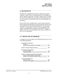
5) Cupfeed Motor - both stator and feedback using supplied 4conductor and 8-conductor cable.
Note: Individual conduit runs (Liguidtight) should be provided
for the 4-conductor motor leads and the 8-conductor resolver
feedback cable to reduce EMI pick-up on the resolver leads.
Figure 1 shows an example of using a "T" conduit fitting to
separate the two conduits. If only one Liquid-tight run is made to
the motor, run it to the nearest junction box and then separate the
two runs.
________________________________________________________________________________
Figure 1 - Cupfeed Motor Conduit Routing
HSL-WISVCUP User’s Manual
SYSTEMS Electronics Group
-9-
SECTION 2
INSTALLATION
6) Main Crank Resolver. If machine is already equipped with a
resolver, parallel resolver wiring with existing PLS (R2 of the
M4510 is reference ground). If machine is not equipped with a
resolver, see section 2.5 – Mounting the RSV34-MS1 Resovlver.
In general, when wiring the HSL-WISVCUP, keep all +24VDC and
resolver wiring away from high voltage wiring.
________________________________________________________
2.5 MOUNTING THE RSV34-MS1 RESOLVER
The HSL-WISVCUP is designed to interface to a resolver (not
encoder) for machine timing. If the machine is not already equipped
with a resolver, then the existing encoder will have to be removed and
an RSV34-MS1 resolver will have to be mounted in it's place. If this
is the case, refer to the RSV34-MS1 data sheet for details on
mounting the resolver. Use the RSV-RSCBLE cable to connect the
resolver to the HSL-WISVCUP. Route the resolver cable in a separate
conduit, away from all other high voltage and control wiring. Wire
the cable directly to the 8-pin resolver connector on the M4510.
HSL-WISVCUP User’s Manual
SYSTEMS Electronics Group
- 10 -
SECTION 2
INSTALLATION
________________________________________________________
2.6 HSL-WISVCUP SOFTWARE INSTALLATION
Follow the steps below to install either the Windows or DOS based
setup programs and PLC application program on a PC used to support
the HSL-WISVCUP control system.
________________________________________________________
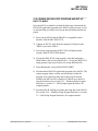
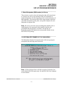
2.6.1 WINDOWS™BASED SETUP PROGRAM
INSTALLATION
The WISVCUP setup program is compatible with Windows
95/98/ME/2000/XP operating systems and is used to:
1) Setup (tune) the user adjustable variables
2) Adjust the timing channel set-points
3) Download the application programs to the M4510 and S4520
4) Download (restore) or upload (save) the user setup variables
5) View “Shift” data.
To install the set-up software, perform the following steps:
1) Insert the HSL-WISVCUP CD into the drive
2) From the Windows desktop, “Click” Start and then select run.
3) From the “Run” dialog box, “Click” the Browse button.
4) Select the drive with HSL-WISVCUP CD. Select the “setup.exe”
file and “Click” Open and then Ok.
5) This will initiate the installation process. Follow the instructions
that appear on the screen to complete the installation process. The
WISVCUP setup program can be executed from the “Systems”
folder located in Programs.
HSL-WISVCUP User’s Manual
SYSTEMS Electronics Group
- 11 -
SECTION 2
INSTALLATION
________________________________________________________
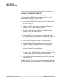
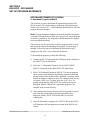
2.6.2 DOS BASED SETUP PROGRAM INSTALLATION
The HSL-WISVCUP set-up software is used to:
1) Download the program to the M4510 module
2) Tune (set-up) the user adjustable variables of the HSLWISVCUP.
3) Download (restore) and upload (save) the user set-up variables
To install the set-up software, perform the following steps:
1) Create one directory off the root for the HSL-WISVCUP called
"HSLSCUP". This will be used to store:
• The "HSLSCUP.EXE" setup program
• The HSL-WISVCUP application programs
• The HSLSCUP set-up data for each bodymaker
Create this directory by typing the following at the DOS prompt:
MD \HSLSCUP<ENTER>
2) Install the disk labeled “HSL-WISVCUP PROGRAMS” into the
drive, switch to that directory and install the “HSL-WISVCUP”
programs by typing the following at the DOS prompt:
CD \HSLSCUP<ENTER>
A:INSTALL<ENTER>
3) Add the HSL-WISVCUP set-up program to your computer's menu
software by creating a selection called "B/M SERVO CUPFEED".
The DOS commands executed for these selections should be:
For the "B/M SERVO CUPFEED" selection:
CD \HSLSCUP
HSLSCUP
CD \
4) To execute the servo cupfeed set-up program, simply select the
corresponding "B/M SERVO CUPFEED" selection from the
menu software's menu.
HSL-WISVCUP User’s Manual
SYSTEMS Electronics Group
- 12 -
SECTION 2
INSTALLATION
________________________________________________________
2.6.3 SYSdev PROGRAM DEVELOPMENT SOFTWARE
INSTALLATION
The SYSdev Program Development software is used to perform online trouble-shooting and program modifications to the HSLWISVCUP. If SYSdev was purchased with the HSL-WISVCUP
package and is not already installed on the your computer, install
SYSdev onto the hard drive of your computer following the steps in
outlined in the SYSdev Program Development manual.
________________________________________________________
2.6.4 APPLICATION PROGRAM INSTALLATION
The application program is a SYSdev based program, loaded into the
M4510 module and the S4520 motion control board. These programs
perform the HSL-WISVCUP logic. The programs are written in a
combination of Ladder logic and High-level. If the user desires to
make program changes or perform on-line monitoring of the programs
that constitute the HSLWISVCUP program, the application programs
will have to be loaded onto the hard drive of the PC used to support
the system. The SYSdev Program Development Software will also
have to be loaded on the PC. To install this program perform the
following:
1) Install the “PROGRAMS” disk into the drive.
2) For each of the " HSLSCUP " directories (created in section
2.6.2), copy all the files from the disk to each of these
subdirectories.
HSL-WISVCUP User’s Manual
SYSTEMS Electronics Group
- 13 -
SECTION 2
INSTALLATION
________________________________________________________
2.7 MODIFY EXISTING PLC PROGRAM
Modify the existing control system PLC program to interface with the
HSL-WISVCUP by incorporating the following into the existing PLC
ladder logic:
1) Add the "Run Mode" output into the existing PLC logic. This
should be "Continuous Mode" OR'd with "Inch Mode" ANDed
with in "Run Mode". Add the "Clutch On" output as well which
should be "on" when the clutch is activated.
2) Add the "Alarm Reset" output. This should be driven directly by
the Alarm Reset push-button of the existing system.
3) Add the "Short Can Alarm" output. This should be driven directly
by the short can alarm detection logic of the existing system and
should go "on" immediately when the short can is detected and
should stay "on" until reset.
4) Add the "Machine Run Enable" input from the HSL-WISVCUP
into the existing system. This sums all the HSL-WISVCUP alarms
into one input that should disable the cupfeed and stop the
machine at BDC. In addition, outputs from the HSL-WISVCUP
are available for each individual alarm. These can be input to the
existing PLC as well so they can be displayed on the existing
alphanumeric display, etc.
5) Add the "Cupfeed Cam In Sync" input from the HSL-WISVCUP
into the existing system. This is "on" when the cupfeed cam is in
sync with the main crank and should be interlocked with the
cupfeed enable logic to prevent the feeding of cups when "off".
Refer to the suggested existing PLC ladder logic at the back of this
manual as an example of how the existing PLC ladder logic might be
modified for the previous interlocks.
HSL-WISVCUP User’s Manual
SYSTEMS Electronics Group
- 14 -
SECTION 2
INSTALLATION
________________________________________________________
2.8 POWER UP HSL-WISVCUP
With the wiring to the HSL-WISVCUP complete, apply power and
verify the following:
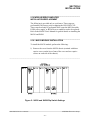
1) Green "PWR" and "RUN" LEDs on M4510 main processor are
"on" and red "FLT" LED is "off".
2) Green "PWR" and "RUN" LEDs on S4520-RDC in M4510 slot 01
are both "on". Green "AMP ENB" LED is "off".
3) LED on B25A20 servo amplifier is "RED" (this is normal when
the amplifier is disabled which it is until the cupfeed motor is
actually running).
4) If the above is not as described, verify that power is applied to
both the M4510 module and the B25A20 amplifier. Also verify all
cables are connected properly the respective modules.
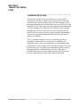
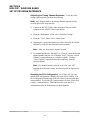
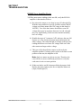
5) Using the set-up program, verify that the M4510 main processor
is loaded with the "HSLSCUP" application program and that the
S4520 in slot 01 is loaded with the "SRVCUPR" application
program. See section 4 or 5 for details on using the setup program
to verify these programs are loaded.
HSL-WISVCUP User’s Manual
SYSTEMS Electronics Group
- 15 -
SECTION 2
INSTALLATION
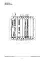
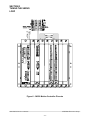
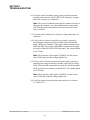
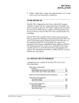
Figure 2 - M4510 Configuration
HSL-WISVCUP User’s Manual
SYSTEMS Electronics Group
- 16 -
SECTION 2
INSTALLATION
________________________________________________________
2.9 HSL-WISVCUP SET-UP
The HSL-WISVCUP is shipped from the factory with the PLC
program "HSLSCUP" loaded in the main processor of the M4510
module (PLC section) and the PLS channel set-point file
"TMGSCUP" loaded in the PLS section of the M4510 module.
Program "SRVCUPR" is loaded in the S4520 motion controller
located in slot 01 of the M4510. These are the standard programs used
to implement the standard HSL-WISVCUP servo cupfeed algorithm.
In some cases, the following user variables and timing channels may
have to be altered to tune the HSL-WISVCUP to the actual
bodymaker it is controlling.
Once the HSL-WISVCUP is installed and the control system is
powered back up, perform the following to set-up and tune the HSLWISVCUP. The set-up is performed using a PC running the set-up
program. See section 4 or 5 for a description of the menus and
variables and how to use the setup program.
________________________________________________________
2.9.1 DEFAULT SET-UP VARIABLES
As shipped, the set-up variables for the S4520-RDC motion control
processor in slot 01 are set to the following defaults:
Cupfeed Stop Position at Short Can:
: 1950
Synchronization Error Limits:
Max Error for "Out of Sync" Disable:
Max Error for Enable Cupfeed Synchronization:
Max Error for "Following Error" Alarm:
: 100
: 500
: 050
Cupfeed Servo PID Gains:
Proportional Gain (P):
Integral Gain (I):
Derivative Gain (D):
: 15.0
: 100
: 25
The above default set-up variables are stored in the data file for
Bodymaker 00.
HSL-WISVCUP User’s Manual
SYSTEMS Electronics Group
- 17 -
SECTION 2
INSTALLATION
________________________________________________________
2.9.2 VERIFY SERVO CUPFEED SET-UP PARAMETERS
Using the set-up program, verify that the user variables of the S4520RDC in slot 01 of the M4510 are set to the defaults as out-lined in
section 2.9.1. If they are not, download the default set-up parameters
for bodymaker #00. These may be changed once the servo cupfeed is
run, but should be set to the defaults to start out. Refer to section 4 or
5 for details on observing these variables and downloading these
variables using the setup program.
________________________________________________________
2.9.3 VERIFY MAIN CRANK RESOLVER
From the "Cupfeed Cam Time/Position Diagnostics" menu of the
setup program, observe the actual main crank position. Verify that the
main crank resolver direction is correct and is linear by barring or
inching the machine forward. The position should increment linearly
through the range of 0 to 4095. If the direction is backwards, reverse
the S1 and S3 leads of the resolver where they connect to the M4510
module. If the position is not linear (increments up then down or does
not increment through full range), verify that the resolver leads are all
connected correctly.
________________________________________________________
2.9.4 SET MAIN CRANK ZERO
Inch the main crank of the bodymaker to back dead center (BDC) and
set the M4510 offset by pressing the "Zero Main Crank" push-button
inside the HSL-WISVCUP enclosure.
HSL-WISVCUP User’s Manual
SYSTEMS Electronics Group
- 18 -
SECTION 2
INSTALLATION
________________________________________________________
2.9.5 VERIFY CUPFEED CAM RESOLVER
From the "Cupfeed Cam Time/Position Diagnostics" menu of the
setup program, observe the actual cupfeed cam position. Verify that
the cupfeed resolver direction is correct and is linear by pulling the
cupfeed cam forward by hand. The position should increment linearly
through the range of 0 to 4095. If the direction is backwards, verify
the resolver is wired per the schematic at the back of this manual. If
the position is not linear (increments up then down or does not
increment through full range), verify that the resolver leads are all
connected correctly.
________________________________________________________
2.9.6 TIME CUPFEED CAM TO MAIN CRANK
Prior to timing the cupfeed cam with respect to the main crank, pull
the cam forward through at least one complete revolution with the
target on the cam passing the timing sensor.
Perform the following to time the cupfeed cam with respect to the
main crank:
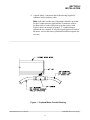
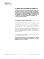
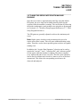
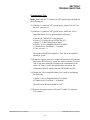
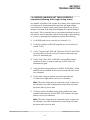
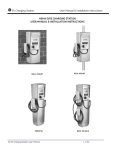
1) Inch or bar the ram to the position where the punch has just
opened to the point where the cup could first be loaded (this is
when the ram is on the back stroke). See figure 3.
________________________________________________________________________________
Figure 3 - Location of Ram at "Cupfeed Time" Position
HSL-WISVCUP User’s Manual
SYSTEMS Electronics Group
- 19 -
SECTION 2
INSTALLATION
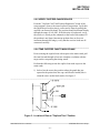
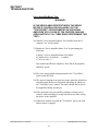
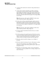
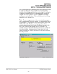
2) Using the "Manual Cupfeed" push-button, feed one cup into the
cupfeed cam and rotate the cam by hand until the cup is fully
loaded into the cam. Rotate the cupfeed cam (with the cup loaded)
into the position where the cup would first be loaded into the cup
locator (see figure 4).
________________________________________________________________________________
Figure 4 - Location of Cupfeed Cam at "Cupfeed Time" Position
________________________________________________________________________________
3) With the cupfeed cam located as described above, press the
"Home Cupfeed Cam" push-button inside the HSL-WISVCUP
enclosure. Make sure the cupfeed cam does not slip from the
"cupfeed time" position when performing this step.
4) At this point in time, the cupfeed cam is timed with respect to the
main crank such that when the machine is running the cupfeed
cam will be in sync with the main crank and load the cup when
the ram has just opened up.
5) The previous steps will automatically set the "Cupfeed Cam
Home Position" by calculating the cupfeed cam offset relative to
the main crank position.
HSL-WISVCUP User’s Manual
SYSTEMS Electronics Group
- 20 -
SECTION 2
INSTALLATION
________________________________________________________
2.9.7 VERIFY CUPFEED TRACKING
By inching the machine, verify that the cupfeed does track (follow)
the main crank. Verify that the cupfeed is correctly in time with crank
in all crank positions.
If the cupfeed oscillates wildly or does not follow the crank, verify
that the PID gains are set correctly (see section 2.9.1 – Default Set-up
Variables). If the gains are set correctly, verify that the motor stator
wiring and feedback wiring are correct (see schematic at the back of
this manual). If they are correct, verify that the analog command
reference from the S4520-RDC to the B25A20 is not swapped (see
schematic at the back of this manual).
________________________________________________________
2.9.8 VERIFY MACHINE OPERATION
Run the machine in normal production (both at low and high speeds
where practical) and verify that the cupfeed cam does track the main
crank in both inch and continuous modes.
Note: After power-up, the cupfeed cam will automatically time itself
when the machine is first run (in inch or continuous). The cupfeed
cam will rotate at a slow speed until it passes the timing sensor and
then will start tracking the main crank.
Verify that the cupfeed cam does stop immediately at the detection of
a short can or tear off (no longer in sync with the ram). The position
the cupfeed will stop at is set by the "Cupfeed Stop Position at Short
Can" parameter (see section 4.6.1 – Windows Setup Program
Reference or section 5.3 – DOS Setup Program Reference).
Verify that the cupfeed solenoid feeds cups properly.
Note: The positive cupfeed sequence is different than that of the
standard cupfeed. With the positive cupfeed, the first can is punched
on the second stroke after the cupfeed is opened. Two additional
strokes will have to be made (with air strip and die protect enabled)
after the cupfeed is turned "off" to process the cups in the cam.
Modify the existing PLC die protect and cupfeed logic as necessary to
achieve this. The HSL-WI6 high speed logic option performs the
cupfeed logic as outlined in the preceding sequence.
HSL-WISVCUP User’s Manual
SYSTEMS Electronics Group
- 21 -
SECTION 2
INSTALLATION
Verify that the Cupfeed Cam is disabled in BAR mode. Activate the
clutch in Bar mode and verify that the C1 contactor for the servo
amplifier is not activated. This makes sure that the Cupfeed servo
motor is disabled while activating the clutch in Bar mode.
The Machine Is Now Set-Up And Ready To Run!
HSL-WISVCUP User’s Manual
SYSTEMS Electronics Group
- 22 -
SECTION 2
INSTALLATION
________________________________________________________
2.10 MODULE/SERVO AMPLIFIER
INSTALLATION/REPLACEMENT
The following is provided only as a reference. These steps are
performed by the factory prior to shipping the HSL-WISVCUP.
These steps need only be performed in the event the M4510 module,
P4500 power supply, or B25A20 servo amplifier need to be replaced.
Refer to the M4500 User's Manual for general details on installing the
M4510 and P4500.
________________________________________________________
2.10.1 M4510 MODULE INSTALLATION
To install the M4510 module, perform the following:
1) Remove the cover from the M4510 chassis (retained with three
captive screws on the lower front of the cover and two captive
screws on each side of the chassis).
________________________________________________________________________________
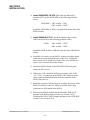
Figure 5 - S4520 and S4568 Dip Switch Settings
HSL-WISVCUP User’s Manual
SYSTEMS Electronics Group
- 23 -
SECTION 2
INSTALLATION
2) Install S4520-RDC (SLOT0-1): Set the slot address dip
switches (SW1) on the S4520-RDC to the following positions
(slot1):
S4520-RDC: SW1 switch1 = "ON"
SW1 switch2 = "OFF"
Install the S4520-RDC in Slot0-1 (second slot from the left) of the
M4510 chassis.
3) Install S4568 (SLOT1-0): Set the slot address dip switches
(SW1) on the S4568 to the following positions (slot0):
S4568:
SW1 switch1 = "OFF"
SW1 switch2 = "OFF"
Install the S4568 in Slot1-0 (fifth slot from the left) of the M4510
chassis.
4) Install the cover back over the M4510, making sure all the board
connectors protrude through the slots in the cover. Tighten the
three captive screws on the lower front of the cover and the two
captive screws on each side of the chassis.
5) Mount the M4510 chassis to the HSL-WISVCUP back panel
using four 8-32 screws.
6) With power "off", install the P4500 power supply cable to the
+5/C/+12/C/-12 connector on the M4510. The connector on the
cable is polarized and should mate with the connector on the
M4510 only one way.
7) Install the respective field wiring arms on all the I/O boards of the
M4510 (I/O slots0-1 and 1-0). Make sure all the field wiring
connectors are fully mated in the M4510.
8) Power-up the M4510 module and download the "HSLSCUP"
program to the M4510 main processor (see section 2.10.4).
Download the "SRVCUPR" program and data to the S4520-RDC
in slot0-1 (see section 2.10.5).
HSL-WISVCUP User’s Manual
SYSTEMS Electronics Group
- 24 -
SECTION 2
INSTALLATION
________________________________________________________
2.10.2 P4500 POWER SUPPLY INSTALLATION
To install the P4500, perform the following steps:
1) Mount the P4500 to the HSL-WISVCUP in the mounting holes
next to the M4510 (left side) using two 8-32 screws.
2) Install the P4500 power supply cable to the +5/C/+12/C/-12
connector on the M4510. The connector on the cable is polarized
and should mate with the connector on the M4510 only one way.
3) With power to the P4500 L, N, G field wiring connector "off",
connect this connector to the P4500 input power connector.
HSL-WISVCUP User’s Manual
SYSTEMS Electronics Group
- 25 -
SECTION 2
INSTALLATION
________________________________________________________
2.10.3 B25A20 SERVO AMPLIFIER INSTALLATION
To install the B25A20 Servo Amplifier, perform the following steps:
1) Set the dip switches on the B25A20 as follows:
1:
2:
3:
4:
5:
6:
7:
8:
9:
10:
Test/Offset
Loop Gain
Current Scaling
Vel Loop Integrator
Duty Cycle Feedback
Velocity Feedback
Velocity Direction
Cont Current Reduction
Integrate Cap
60/120 Phasing
:
:
:
:
:
:
:
:
:
:
OFF
ON
OFF
ON
OFF
OFF
OFF
OFF
OFF
ON
2) Verify both the "Current Limit" and "Ref In Gain"
potentiometers on the B25A20 are turned fully clockwise for
maximum gain (these are multi-turn pots and should be turned
clockwise at least 14 times to ensure they are at the maximum
gain settings).
3) Verify "Loop Gain" potentiometer on B25A20 is turned fully
counter-clockwise (14 times) for minimum loop gain.
4) Remove the cover of the B25A20 and verify that the J1 jumper on
the PC board has been removed (cut out). This is a zero ohm
surface mount resistor. If it has not been removed, carefully cut it
out with a pair of side cutters. This inverts the Inhibit input
turning it into an enable input. Install the cover back on the
B25A20.
5) Mount the B25A20 to the side of the PS300W-96V power supply
using the supplied 8-32 hardware.
6) Wire the MOTOR A, B, and C stator leads to the P2 connector
along with the high power and ground leads. Be sure to connect
the MOTOR A, B, and C stator leads per the schematic at the
back of this manual, otherwise the motor will not run correctly
(jerk or stall).
7) Connect the P1 Molex connector to the P1 connector of the
B25A20.
HSL-WISVCUP User’s Manual
SYSTEMS Electronics Group
- 26 -
SECTION 2
INSTALLATION
________________________________________________________
2.10.4 DOWNLOAD HSLSCUP PROGRAM AND SET-UP
DATA TO M4510
Once the M4510 is installed, perform the following to download the
HSLSCUP application program to the M4510 main processor as well
as download the previously saved set-up data and timing channel setpoints:
1) Power up the M4510 and the IBM PC or compatible used to
interface with the HSL-WISVCUP.
2) Connect an RS-232 cable from the computer COM port to the
"PROG" port on the M4510.
3) Execute the setup program (WISVCUP for Windows based
systems, HSL-SCUP for DOS based).
4) If using the HSL-SCUP setup program, select the bodymaker
(B/M number) that is being interfaced to. If using the WISVCUP
setup program, open a previously saved setup data table file.
5) Select Bodymaker set-up (M4510 PROG PORT).
6) Download the HSLSCUP application program to the M4510. The
current program ident, revision, and checksum for both the
program to be loaded (on disk) and for the program already
loaded in the M4510 will be displayed. Confirm your choice to
start the download. See section 4.2.3 – Windows Setup Program
Reference or section 5.2 – DOS Setup Program Reference for
complete details.
7) Download the PLS timing set-points and setup data to the M4510.
See section 4.2.4 – Windows Setup Program Reference or section
5.2 – DOS Setup Program Reference for complete details.
HSL-WISVCUP User’s Manual
SYSTEMS Electronics Group
- 27 -
SECTION 2
INSTALLATION
________________________________________________________
2.10.5 DOWNLOAD SRVCUPR PROGRAM AND SETUP DATA TO S4520-RDC IN SLOT01
Perform the following to download the SRVCUPR application
program to the S4520-RDC motion control processor as well as
download the previously saved set-up data:
1) Power up the HSL-WISVCUP and the PC used to interface with
the HSL-WISVCUP.
2) Connect an RS-232 cable from the computer COM port to the
"MOTION" port on the S4520-RDC in slot 01.
3) Execute the setup program (WISVCUP for Windows based
systems, HSL-SCUP for DOS based).
4) If using the HSL-SCUP setup program, select the bodymaker
(B/M number) that is being interfaced to. If using the WISVCUP
setup program, open a previously saved setup data table file.
5) Select Cupfeed Set-up (S4520 Slot-01 MOTION PORT).
6) Download the SRVCUPR application program to the S4520.
Confirm your choice to start the download. See section 4.2.3 –
Windows Setup Program Reference or section 5.3 – DOS Setup
Program Reference for complete details.
7) Download the previously saved set-up data to the S4520-RDC.
See section 4.2.4 – Windows Setup Program Reference or section
5.3 – DOS Setup Program Reference for complete details.
8) Verify that the cupfeed cam is timed correctly to the main crank
(see section 2.9.6).
The HSL-WISVCUP is now ready to run, loaded with the application
programs, timing set-points, and set-up data previously saved for the
respective bodymaker.
HSL-WISVCUP User’s Manual
SYSTEMS Electronics Group
- 28 -
SECTION 3
TUNING THE SERVO
LOOP
This section describes the PID servo loop in general (as used with the
cupfeed motor), provides definitions of the PID gains, plus tips on
tuning the servo loop.
Note: The defaults PID gains have been determined to be the
optimum gains. The PID gains should only be changed by qualified
personnel familiar with closed loop servo control. Instability
(oscillation) of the servo motor can result if the PID gains are set
incorrectly.
________________________________________________________
3.1 DESCRIPTION OF PID SERVO LOOP
In the servo cupfeed application, the intention is to have the cupfeed
track (follow) the main crank position as accurately as possible. This
is accomplished using an individual S4520 motion controller
implementing a PID servo loop for the cupfeed cam.
Essentially the PID loop determines the difference between the main
crank position and the actual servo motor position and generates a
torque to null the difference to zero (or as minimal as is practical).
This is done continuously through out the main crank stroke. Full
access to the PID gains allows the servo loop to be tuned to provide
the optimum balance between acceptable error and minimum running
current.
The servo motor control is implemented with a high speed (0.5msec
update) PID servo loop. The main crank position is used as the
reference for the servo loop with the servo motor position used as the
feedback. Both main crank position and servo motor positions are
generated with resolvers to provide the highest degree of reliability
and noise immunity. Both resolver format signals are converted to
digital with a resolution of 12-bits (0-4095).
The PID servo loop is implemented in the S4520 motion control
processor of the M4510. This board interfaces to the servo amplifier
which drives the motor. The S4520 motion controller provides a +/-10
Volt analog signal to the amplifier which is essentially a "torque"
command.
HSL-WISVCUP User’s Manual
SYSTEMS Electronics Group
- 29 -
SECTION 3
TUNING THE SERVO
LOOP
The servo amplifier will supply a current to the servo motor which is
proportional to the +/-10 Volt analog command. The servo motor in
turn generates a torque to the load which is again proportional to this
current. Thus the +/-10 Volt analog signal from the S4520 can be
considered a “torque” command (both positive and negative torque)
to the motor.
The stability and responsiveness of the servo motor is defined by the
combination of the PID gains. These gains determine whether the
servo loop is stable (under-damped, over-damped, or critically
damped) or unstable (oscillatory). Each individual (P), (I), and (D)
gain is used to generate an individual error term. The summation of
these three error terms is the “torque” command that is applied to the
servo amplifier which drives the motor.
In general, the gains are determined empirically by observing the
response of the system (both step response and while running
continuously) and adjusting the gains until the desired response (and
required torque) are achieved. The gains are set using the set-up
program. The following describes the individual (P), (I), and (D)
gains and corresponding error terms.
________________________________________________________
3.2 PROPORTIONAL (P) GAIN
The proportional (P) gain is used to create an error term which is
“proportional” to the difference between the main crank position and
the servo motor position. The higher the proportional error term, the
higher the torque generated to null the error. For a specific amount of
error, the higher the (P) gain, the higher the torque generated.
Note: By itself, the (P) term cannot null the error to zero since a
torque is only generated when there is a difference between the main
crank position and servo motor.
HSL-WISVCUP User’s Manual
SYSTEMS Electronics Group
- 30 -
SECTION 3
TUNING THE SERVO
LOOP
The (P) gain is used in conjunction with the other gains to define the
system stability and responsiveness. The higher the (P) gain, the
higher the responsiveness.
Note: Too high of a (P) gain will cause the system to be unstable
(oscillate) because the system cannot respond quick enough.
Excessive current will also be drawn which is undesirable. Too low a
gain will cause excessive following error to the point of instability
depending on where the (I) gain is set. In general, the (P) gain is used
to overcome high frictional loads (higher (P) for higher friction).
________________________________________________________
3.3 INTEGRAL (I) GAIN
The integral (I) gain is used to create an error term that is proportional
to the cumulative difference (error) between the main crank position
and servo motor position. Thus for a fixed amount of error, the torque
generated due to the integral error term will continue to increase at a
rate proportional to the (I) gain. The higher the integral error term, the
faster the torque generated to null the error will increase. This term is
used to null a fixed error to zero since a torque of whatever amplitude
will be generated to null the error to zero.
Note: Without the other gains ((P) and (D)), the system would be
unstable.
As with the (P) gain, the higher the integral gain, the higher the
responsiveness.
Note: Too high of an (I) gain will cause the system to be unstable
(oscillate) because the system cannot respond quick enough. Too low
an (I) gain will cause excessive following error since at low (I) gains,
the (P) gain would be mostly responsible for nulling the error. The
system will not be unstable if the (I) gain is set to zero.
HSL-WISVCUP User’s Manual
SYSTEMS Electronics Group
- 31 -
SECTION 3
TUNING THE SERVO
LOOP
________________________________________________________
3.4 DERIVATIVE (D) GAIN
The derivative (D) gain is used to create an error term which is
proportional to the rate of change of error between the main crank
position and servo motor position. Thus for a fixed amount of error,
the torque generated due to the derivative error term will be zero (rate
of change is zero). This error term is only generated when the amount
of error is changing. The higher the rate at which the error changes,
the higher the derivative error term. This term is primarily used to
stabilize the servo loop. It is used to reduce ringing in underdamped
responses or to provide fundamental stability to loops that would
otherwise be unstable.
There is a definite comprise between to much (D) gain and not
enough (D). With too little, the system may go unstable or be
marginally stable. Also excess ringing with a corresponding longer
settling time to a step response will occur if the (D) gain is too low. If
the derivative gain is too high, the system response will be reduced
and high frequency oscillations may occur, not to the point of
instability but to the point where higher current will be drawn and
excessive high frequency torque will be applied to the load.
HSL-WISVCUP User’s Manual
SYSTEMS Electronics Group
- 32 -
SECTION 3
TUNING THE SERVO
LOOP
________________________________________________________
3.5 TUNING THE SERVO MOTOR WITH MACHINE
RUNNING
Once the servo motor is approximately tuned (by using the default
PID gains), the servo loop can be further tuned by observing the
response while the machine is running. This can be done by observing
the positive and negative peak position error using the set-up program
(see section 4.6.2 – Windows Setup Program Reference or 5.3 – DOS
Setup Program Reference).
The PID gains are generally adjusted to achieve the minimum peak
errors.
Note: Higher gains, which are used to minimize the error, also
require more motor current. This will cause additional heating in the
motor. Therefore, use the lowest possible gains to achieve acceptable
running error.
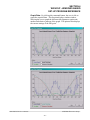
In addition, the "Acquire Data Signatures" selection can be used to
acquire the "current", "error", "actual profile", and "reference profile"
for one stroke while the machine is running. This data is sampled
every millisecond and saved to a text file. This file can be uploaded
into an Excel worksheet and viewed in a chart as well as scaled and
summarized. This allows the corresponding waveforms to be
observed and analyzed.
HSL-WISVCUP User’s Manual
SYSTEMS Electronics Group
- 33 -
SECTION 3
TUNING THE SERVO
LOOP
Figure 6 - S4520 Motion Controller Pin-outs
HSL-WISVCUP User’s Manual
SYSTEMS Electronics Group
- 34 -
SECTION 4
WISVCUP - WINDOWS BASED
SET-UP PROGRAM REFERENCE
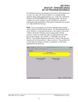
The Windows based set-up program is menu driven, allowing the user
to easily view data, alter set-up variables or set machine timing
(machine offset, timing signal locations, etc.), using a PC running the
Windows (95/98/ME/2000/XP/NT) operating system. The set-up
variables are used to configure and tune the M4510 to match the
configuration and performance of the specific bodymaker (see section
2.9 – HSL-WISVCUP Set-Up).
Note: The set-up program is an on-line communications program
used to interface with the M4510 module. The data displayed and set
in the windows is communicated directly to the module, while in the
“Online” edit mode. Therefore, prior to going online with the
processor, make sure an RS-232 cable is connected from the COM
port on the computer to the "PROG" or “MOTION” port on the
M4510. The variables displayed while in the “Online” edit mode are
read directly from the processor. Data is saved to a “Set-up Data” file
(*.sdt) whenever changes are made to a parameter or if the data is
uploaded from the processor.
HSL-WISVCUP User’s Manual
SYSTEMS Electronics Group
- 35 -
SECTION 4
WISVCUP - WINDOWS BASED
SET-UP PROGRAM REFERENCE
________________________________________________________
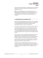
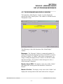
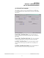
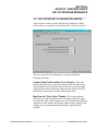
4.1 GENERAL DESCRIPTION
Title Bar: At the top of the window is the “Title Bar”. The title bar
is used to display the name of the working “Set-up Data” file, as well
as, the name of the active “Window”. The title bar is dark if the
window is active and grayed if another window is active. The color
depends on the settings of the Display Properties of the Control Panel.
Status Bar: At the bottom of the window is the “Status Bar”. The
status bar is used to display system messages, online or offline mode,
as well as, the current time and date as set by the operating system.
The system messages panel displays general information about
operation of the system. The Online/Offline mode panel displays the
status of the current set-up program mode of operation. The mode of
operation can be changed by simply double clicking the online/offline
mode panel.
Hot Keys: Hot keys are activated by holding down the “ALT” key
and simultaneously pressing the underlined letter of the desired
function. Almost every function can be activated by either pressing a
series of hot keys or using the “TAB” key to move between fields.
Online/Offline Modes: The set-up program allows the user to
make changes while “Online” with the processor. The “Offline”
mode is used to preset parameters prior to download. All functions
are available to the user while “Online”, however, specific “Online”
functions are disabled in the “Offline” edit mode.
Note: Offline changes can only be made by enabling “Offline
Editing”, accessed under the “Edit” menu.
Getting Help: The entire contents of the user’s manual is contained
within the help file. Pressing Ctrl+H will display the help file
window. Pressing the F1 key will display the contents file. Hot spots
allow jumps to other topics to display additional information as
desired. Selecting About WISVCUP from the Help menu will display
a dialog box listing information about the current revision of the setup
program and how to obtain technical support.
HSL-WISVCUP User’s Manual
SYSTEMS Electronics Group
- 36 -
SECTION 4
WISVCUP - WINDOWS BASED
SET-UP PROGRAM REFERENCE
________________________________________________________
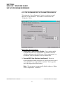
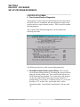
4.2 THE FILE MENU
The “File” menu allows the user to perform the following functions:
•
•
•
•
•
•
•
•
Create a “New” set-up “Data File”.
Open an existing “Data File”.
Save any changes made to the current “Data File” to disk.
Upload (save) Data from the Processor.
Download a SYSdev (.sdv) program to the processor
Download (restore) Data from the current set-up “Data File” to
the processor.
Print a Report of the current set-up parameters.
Exit the set-up program.
HSL-WISVCUP User’s Manual
SYSTEMS Electronics Group
- 37 -
SECTION 4
WISVCUP - WINDOWS BASED
SET-UP PROGRAM REFERENCE
________________________________________________________
4.2.1 THE SET-UP DATA FILE
The set-up “Data File” (.sdt) is a binary access file, designed for fast
file I/O operation. When the set-up program is first invoked, the
default set-up parameters are loaded into memory. If changes are
made to any of the set-up parameters (either online or offline), as well
as shift data, the user will be flagged to “Save Changes” upon exit of
the program.
Note: Any windows based “Set-up” program can open a set-up
“Data File”, however, the data tables will not be properly aligned.
The user will be alerted to the problem if a set-up data file has been
created by either a different set-up program or a different revision of
the software.
The set-up “Data File” is similar to that of a word processing file.
When the program first starts, a default file is loaded and the user is
able to make any changes as desired. The set-up program is unaware
of the settings and parameters that exist within the processor.
Therefore, to normalize the set-up program, the user should define or
open an existing file, then upload “All” variables from the processor.
This allows the user to either create a backup of the data or maintain
an existing file. The user can even open a data file for another
bodymaker, save the file to a new name, make the necessary changes
and simply download the new parameters to another processor.
The following functions can be accessed any time, from any set-up or
display windows.
New: To create a “New” data file, select “New” from the “File”
menu or press “Ctrl + N”. This creates a completely new file, loaded
with the default variables and the word “[unnamed]” is displayed in
the title bar. If any changes were made to the existing file, the user is
prompted to save changes to the existing file.
Open: To “Open” and existing data file, select “Open” from the
“File” menu or press “Ctrl + O”. This displays a dialog box allowing
the user to select an existing data file to open. The name of the file
will be displayed in the title bar. If any changes were made to the
existing file, the user will be prompted to save any changes before
terminating the program.
HSL-WISVCUP User’s Manual
SYSTEMS Electronics Group
- 38 -
SECTION 4
WISVCUP - WINDOWS BASED
SET-UP PROGRAM REFERENCE
Save: To “Save” data file to disk, select “Save” from the “File”
menu or press “Ctrl + S”. This displays a dialog box allowing the
user to select a folder and enter a name for the file. The user will be
notified if the file already exists and the extension “.sdt” will
automatically be added to the file name. If this is a “New” file, the
user will be prompted to enter a file name.
Save As: To save the data file to a new name, select “Save As”
from the “File” menu.. This displays a dialog box allowing the user
to select a folder and enter in a new name for the file. The user will
be notified if the file exists and the extension “.sdt” will automatically
be added to the file name.
Export Shift Data…: This function allows the user to export the
shift data to a “Tab Delimited” text file. This allows the user to easily
use the shift data to produce production reports.
________________________________________________________
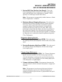
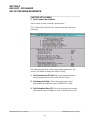
4.2.2 UPLOAD (SAVE) DATA
The “Set-up” program allows the user to upload blow-off parameters,
timing channel set-points and shift data from the M4510 and S4520
into a set-up “Data File”. This function is accessed from the “File”
menu and the user is given the choice of the following options:
HSL-WISVCUP User’s Manual
SYSTEMS Electronics Group
- 39 -
SECTION 4
WISVCUP - WINDOWS BASED
SET-UP PROGRAM REFERENCE
M4510 PLC: This option uploads (reads) set-up parameters,
machine timing set-points and shift data from the M4510, only.
S4520 Motion Control: This option uploads (reads) set-up and
tuning parameters from the S4520 Motion Control Board, only.
________________________________________________________
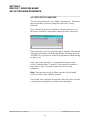
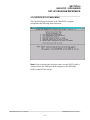
4.2.3 DOWNLOAD PROGRAM
The “Set-up” program allows the user to “Download” any SYSdev
program file to either the M4510 or S4520.
Note: To “Download” a SYSdev program to the processor, the
program must be “Online”. If “Online” mode cannot be achieved,
program download will not be executed. If the program is currently
“Offline”, the user will be prompted to first go “Online”.
HSL-WISVCUP User’s Manual
SYSTEMS Electronics Group
- 40 -
SECTION 4
WISVCUP - WINDOWS BASED
SET-UP PROGRAM REFERENCE
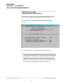
Once selected, and the set-up program “Online” with the processor, a
dialog box will be displayed, allowing the user to select the SYSdev
file to download.
Note: Only the files with the “.sdv” file extension will be displayed.
It is important to keep in mind that only a valid M4510 PLC SYSdev
file can be downloaded through the set-up program. Care should be
taken when selecting a program to download.
Once selected, a message box is displayed informing the user of the
current program, revision and checksum of the program loaded in the
processor, as well as, that of the selected program. The user must
confirm their selection by clicking the “Yes” command button. After
the user confirms their choice, program download is initiated and the
current program download address is displayed. When program
download is complete, the user is prompted to acknowledge. Control
is passed back to the main program and the set-up program remains in
an “Online” edit mode.
HSL-WISVCUP User’s Manual
SYSTEMS Electronics Group
- 41 -
SECTION 4
WISVCUP - WINDOWS BASED
SET-UP PROGRAM REFERENCE
________________________________________________________
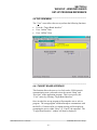
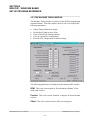
4.2.4 DOWNLOAD (RESTORE) DATA
The set-up program allows the user to download “Set-up”
parameters, timing channel set-points and shift data to the M4510 or
S4520 from the set-up “Data File”. This function is accessed from
the “File” menu and the user is given the choice of the following
options:
M4510 PLC: This option downloads set-up parameters, machine
timing set-points and shift data to the M4510, only.
S4520 Motion Control: This option downloads set-up and tuning
parameters to the S4520 Motion Control Board, only
Note: Only the values contained within the current data file are used.
If the validity of the current data file is questionable, review the data
in an “Offline” mode prior to download.
HSL-WISVCUP User’s Manual
SYSTEMS Electronics Group
- 42 -
SECTION 4
WISVCUP - WINDOWS BASED
SET-UP PROGRAM REFERENCE
________________________________________________________
4.2.5 PRINT REPORT
The “Set-up” program allows the user to generate a “Report” printout
of all the set-up parameters, timing channel set-points and shift data.
This function is accessed from the “File” menu.
At the top of each page, the report displays the name of the set-up file
being printed. At the bottom of each page is the date and time the
document was printed, as well as, the page number.
To printout a report of the settings contained in the set-up “Data File”,
perform the following:
1) From the “File” menu, select “Print Report” or press “Ctrl + P”.
2) This displays the “Print Setup” dialog box, allowing the user to
select a printer, as well as, the paper size and orientation. Once
the user selects “OK”, the report is generated and sent to the
specified printer device.
Note: This function makes use of the windows print manager, which
allows the user to continue with their work while the document is
being printed.
HSL-WISVCUP User’s Manual
SYSTEMS Electronics Group
- 43 -
SECTION 4
WISVCUP - WINDOWS BASED
SET-UP PROGRAM REFERENCE
________________________________________________________
4.3 THE EDIT MENU
The “Edit” menu allows the user to perform the following functions:
•
•
•
Enable/Disable Offline Editing.
Set-up the Comm Port.
Edit the Set-Up Passcode.
________________________________________________________
4.3.1 ENABLE OFFLINE EDITING
This function allows the user to perform “Offline” editing on the
currently loaded set-up data file. This allows the user the ability to
make any necessary changes to the set-up parameters while offline
with the processor.
If offline editing is not enabled, the user is only able to view the setup parameters and shift data. When the program is first invoked, the
default setting is offline editing disabled. The user will need to
specifically select “Enable Offline Editing” from the edit menu (or
press function key F2) to enable/disable this feature.
HSL-WISVCUP User’s Manual
SYSTEMS Electronics Group
- 44 -
SECTION 4
WISVCUP - WINDOWS BASED
SET-UP PROGRAM REFERENCE
________________________________________________________
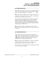
4.3.2 SET-UP COMM PORT
This function allows the user to specify the serial communications
port and rate to communicate with the M4510. The PROG and
MOTION communicates at 9600 baud.
The option to select the 19200 baud rate is to allow the user to
communicate via the S4516 serial communications board. In most
cases, the user will only need to specify the communications port and
leave the baud rate at 9600.
If communication problems occur, make sure there is a secure
connection from the PC to the PLC. Then check the Comm port. In
most cases, the user will only need to select a new Comm port. If
communication problems persist, there may be another program
causing a conflict with the port. Check the port configuration from
the “Settings” folder.
HSL-WISVCUP User’s Manual
SYSTEMS Electronics Group
- 45 -
SECTION 4
WISVCUP - WINDOWS BASED
SET-UP PROGRAM REFERENCE
________________________________________________________
4.3.3 EDIT SET-UP PASSCODE
The edit “Set-up Passcode” is an “Online” function only. This allows
the user the ability to directly change the value of the “Set-up
Passcode”.
Once selected, an input box is displayed, allowing the user to view
the current “Passcode” setting and to change the value if necessary.
If the passcode is set to zero, passcode entry is disabled. The operator
can press the Set-up key on the Keypad/Display and simply press the
<ENTER> key to gain access to the set-up parameters without having
to enter a zero.
If the value of the “Passcode” is set somewhere between 1 and
65,000, “Passcode Entry” is enabled. This requires the operator to
enter in the “Correct” passcode to gain access to the set-up
parameters.
Note: Passcode entry is only in effect when the “Set-up Enable”
selector switch is in the “Disable” position.
If an invalid value is entered, the passcode value will not be reset and
a message box notifying the user of the error is displayed.
HSL-WISVCUP User’s Manual
SYSTEMS Electronics Group
- 46 -
SECTION 4
WISVCUP - WINDOWS BASED
SET-UP PROGRAM REFERENCE
________________________________________________________
4.4 THE VIEW MENU
The “View” menu allows the user to perform the following functions:
•
•
•
View the “Target Board Interface”
View “Online” Data
View “Offline” Data
________________________________________________________
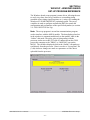
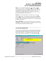
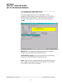
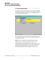
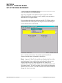
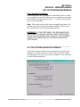
4.4.1 TARGET BOARD INTERFACE
This function allows the user to view fault codes, S3000 network
communication error codes and review the current “Ident” and
“Revision” of the application program. This is accessed by the
“View” menu, by selecting “Target Board Interface”.
Once invoked, the set-up program will prompt the user to select a
program. The setup program will then attempt to communicate with
the M4510. If unsuccessful, a warning message will be displayed,
prompting the user to either “Retry” or “Cancel” the operation. The
“Target Board Interface” window will then be displayed.
HSL-WISVCUP User’s Manual
SYSTEMS Electronics Group
- 47 -
SECTION 4
WISVCUP - WINDOWS BASED
SET-UP PROGRAM REFERENCE
HSL-WISVCUP User’s Manual
SYSTEMS Electronics Group
- 48 -
SECTION 4
WISVCUP - WINDOWS BASED
SET-UP PROGRAM REFERENCE
________________________________________________________
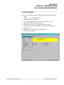
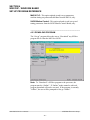
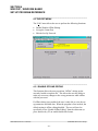
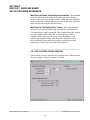
4.4.2 VIEW ONLINE DATA
This function allows the user to go “Online” with either the M4510 or
S4520. This is accessed by the “View” menu, by selecting “Online
Data” or by simply pressing the “F3” function key.
Note: The user can be toggled between “Offline” and “Online” by
simply double clicking on the “Online” or “Offline” panel displayed
in the status bar at the bottom of the window.
Once invoked, the set-up program will to open the Comm port and
attempt to communicate with the processor. If unsuccessful, a
warning message will be displayed prompting the user to either
“Retry” or “Cancel” the operation. If the operation is canceled and
communication with the processor cannot be established the system
will be placed in an “Offline” mode.
Note: Anytime while the set-up program is “Online” with the
processor and communication is interrupted, a warning message will
be displayed.
________________________________________________________
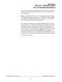
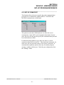
4.4.3 VIEW OFFLINE DATA
This function allows the user to place the set-up program in an
“Offline” mode. This is accessed by the “View” menu, by selecting
“Offline Data” or by simply pressing the “F4” function key. All
values displayed in “Offline” edit mode reflect the actual values
contained in the currently loaded set-up data file.
Note: The program can be toggled between “Online” and “Offline”
by simply double clicking on the “Online” or “Offline” panel
displayed in the status bar at the bottom of the window.
Once invoked, the set-up program will cease communication with the
processor and close the Comm port.
HSL-WISVCUP User’s Manual
SYSTEMS Electronics Group
- 49 -
SECTION 4
WISVCUP - WINDOWS BASED
SET-UP PROGRAM REFERENCE
________________________________________________________
4.5 THE BODYMAKER MENU
The “Bodymaker” menu allows the user to select one of five different
Display/Set-up windows, used to modify set-up parameters, view shift
data, adjust timing channel set-points or receive feedback about the
current status of the control system
Once a window menu item is selected, a check mark is placed next to
the selected item, and the selected window is displayed and the name
is changed in the title bar.
Note: “Read” only variables are displayed in blue with a gray
background. Any variables that can be altered by the user are
displayed in black with a white background. In most cases, a
parameter that can be changed by the user will have associated with it
increment and decrement controls. The user can either click on the
desired parameter to adjust and enter in a new value, or use the
increment or decrement controls to change the value by 1 unit.
HSL-WISVCUP User’s Manual
SYSTEMS Electronics Group
- 50 -
SECTION 4
WISVCUP - WINDOWS BASED
SET-UP PROGRAM REFERENCE
________________________________________________________
4.5.1 THE BODYMAKER MAIN DISPLAY WINDOW
The bodymaker “Main Display” window is used to display the
general state of the control system. This window is selected from the
“Bodymaker” menu.
The following is a list of the functions of the “Main Display”
window.
Messages: The “Messages” display is continuously updated. It
displays alarm and status messages specific to the M4510, as well as,
the current “Online” or “Offline” status of the set-up program. By
simply scrolling the display the user is able to view all active alarm
and status messages. If no alarm or status messages are active, a
default message is displayed.
Machine Speed SPM: This display is only active while “Online”
and displays the current speed of the machine in “Strokes Per
Minute”.
Machine Position: This display is only active while “Online” and
displays the current position to the main crank resolver in degrees.
HSL-WISVCUP User’s Manual
SYSTEMS Electronics Group
- 51 -
SECTION 4
WISVCUP - WINDOWS BASED
SET-UP PROGRAM REFERENCE
________________________________________________________
4.5.2 THE BODYMAKER SET-UP PARAMETERS WINDOW
The bodymaker “Set-up Parameters” window is used to view and
adjust the set-up parameters. This window is selected from the
“Bodymaker” menu.
Brake Wear Compensation:
1) Brake Wear Compensation Enable: This is used to enable
or disable the brake wear compensation. To disabled, click the
checkbox and remove the checked state. If the compensation is to
be enabled, click the checkbox to set the checked state.
2) Desired BDC Stop Position (Low Speed): This is the
desired stopping location (in degrees) for a BDC stop at low speed
when the brake wear compensation is enabled. This is typically
set to 000 degrees (back dead center).
Note: This parameter is automatically disabled whenever “Brake
Wear Compensation” is disabled.
HSL-WISVCUP User’s Manual
SYSTEMS Electronics Group
- 52 -
SECTION 4
WISVCUP - WINDOWS BASED
SET-UP PROGRAM REFERENCE
3) Desired BDC Stop Position (Low Speed): This is the
desired stopping location (in degrees) for a BDC stop at high
speed when the brake wear compensation is enabled. This is
typically set to 000 degrees (back dead center).
Note: This parameter is automatically disabled whenever “Brake
Wear Compensation” is disabled.
4) Maximum Allowed Stopping Response: This defines the
maximum allowed brake response before the "Brake Response
Too Long" alarm is generated. If the actual brake response
(number of degrees from when the brake is activated to the
position where the press ends up at rest when a BDC stop is
performed) is longer than this number, the alarm is generated. If
the actual brake response is less, the alarm is not generated. Set
this parameter to the value where the brake response is considered
too long and service to the brake should be performed (typically
270 to 300 degrees).
Bodymaker Running Speeds:
1) Running Bodymaker Low Speed (SPM): This is the speed
(in strokes per minute) the bodymaker will run when in low (inch)
speed.
2) Running Bodymaker High Speed (SPM): This is the speed
(in strokes per minute) the bodymaker will run when in high
(cont./single) speed.
Trimmer Speed References:
1) Trimmer Maximum Speed (CPM): The "Trimmer Maximum
Speed" is used to scale the 0-10VDC analog output such that
when the bodymaker is running at the speed entered the analog
output is 10 volts. This is typically set to the running high speed
of the Bodymaker or slightly higher.
2) Trimmer Idle Speed (CPM): This parameter determines the
speed the trimmer will run at when the bodymaker is stopped (declutched).
Note: This parameter is used to provide the speed reference
when the bodymaker speed is zero. When the bodymaker is
running, the trimmer speed reference is proportional to the speed
of the bodymaker.
HSL-WISVCUP User’s Manual
SYSTEMS Electronics Group
- 53 -
SECTION 4
WISVCUP - WINDOWS BASED
SET-UP PROGRAM REFERENCE
________________________________________________________
4.5.3 THE MACHINE TIMING WINDOW
The Machine Timing window is used to invoke the PLS programming
command menus. From this window, the user can view or adjust the
following parameters:
•
•
•
•
•
Adjust Timing Channel set-points.
Set the Main Crank resolver offset.
Clear or Recall a PLS timing channel.
View the current PLS configuration
Reset the PLS configuration to default settings.
The following parameters are displayed at the bottom of this window:
RPM: This is the current speed in “Revolutions per Minute” of the
main crank resolver.
Position: This is the current “Position” in degrees of the main crank
resolver.
Offset: This is the current resolver offset (set in degrees).
HSL-WISVCUP User’s Manual
SYSTEMS Electronics Group
- 54 -
SECTION 4
WISVCUP - WINDOWS BASED
SET-UP PROGRAM REFERENCE
Scale: This is the scale factor of the resolver or the number of
divisions in one revolution.
Zeroing the Machine (setting the resolver offset): To set
machine zero, perform the following:
1) Connect an RS-232 SYSdev cable from the COM port on the
computer to the “PROG” port on the M4510.
2) From the “Bodymaker” menu, select “Machine Timing”.
3) From the “View” menu, select “Online Data”.
4) Observe the “Position” field at the bottom of the window. Verify
that as the machine is rotated forward, that the position increases
linearly from 0 through 359 degrees. If not, swap the S1 and S3
leads at the resolver connector on the M4510. Then, verify that
the position does indeed increase with forward movement.
5) Position the machine at back dead center.
6) Auto zero the resolver by entering “0” in the “Resolver Offset”
field and clicking the “Set Offset” command button. A message
box will appear, prompting the user to confirm their choice.
Select “Yes” to set the resolver offset.
7) The M4510 will calculate the actual offset value required to make
this the “0” position. The new offset value will be displayed in
the “Offset” field and the position will then read zero.
HSL-WISVCUP User’s Manual
SYSTEMS Electronics Group
- 55 -
SECTION 4
WISVCUP - WINDOWS BASED
SET-UP PROGRAM REFERENCE
Adjusting the Timing Channel Setpoints: To set any of the
timing signal setpoints, perform the following:
Note: Any changes made to the timing channel setpoints will be
saved as part of the setup data file.
1) Connect an RS-232 SYSdev cable from the COM port on the
computer to the “PROG” port on the M4510.
2) From the “Bodymaker” menu, select “Machine Timing”.
3) From the “View” menu, select “Online Data”.
4) Setpoints for a particular channel are either entered in the field or
adjusted by using the increment/decrement controls.
Note: Only one set-point per channel is used.
5) If a channel needs to be “Recalled” or “Cleared”, enter the desired
channel number into the “PLS Channel” field. Click the “Recall
Channel” command button to recall the set-point. Click the
“Clear Channel” command button the completely clear the
selected channel.
Note: If a channel has been cleared or the “On” and “Off”
setpoints have the same setting, the set-point will be displayed as
“*****”.
Resetting the PLS Configuration: As an aid to the user, the
current PLS configuration is displayed as part of this window. The
PLS configuration should only need to be reset if a new module has
been installed. To reset the PLS configuration, click the “Reset PLS
Config” command button. This function only resets the PLS
configuration to the default settings for the bodymaker.
HSL-WISVCUP User’s Manual
SYSTEMS Electronics Group
- 56 -
SECTION 4
WISVCUP - WINDOWS BASED
SET-UP PROGRAM REFERENCE
________________________________________________________
4.5.4 THE SHIFT DATA WINDOW
This window is used to view the Current Shift data, Last Shift data,
Low and High speed brake responses and to invoke the “End of Shift”
data transfer.
Current Shift - Total Good Cans: This is the total number of
good cans produced so far into the current shift. This is essentially a
can counter.
Current Shift - Total Short Can Faults: This is the total number
of short can faults that have occurred so far into the current shift.
Last Shift - Total Good Cans: This is the total number of good
cans produced in the last (previous) shift. This is essentially a can
counter.
Last Shift - Total Short Can Faults: This is the total number of
short can faults that occurred in the last (previous) shift.
HSL-WISVCUP User’s Manual
SYSTEMS Electronics Group
- 57 -
SECTION 4
WISVCUP - WINDOWS BASED
SET-UP PROGRAM REFERENCE
Note: The current shift data is transferred to the "Last shift" data
when the end of shift input transfers from a "0" to a "1". This can be
at the end of either an 8 or 12-hour shift. This data can also be reset
from this menu by clicking the “Transfer Data” command button.
Lo Speed Brake Response (degrees): This is the number of
degrees from the when the clutch was de-activated (at the BDC (Lo)
timing) to where the bodymaker crankshaft came to rest when a BDC
stop was performed at Low speed. This can be used to determine the
general condition of the brake and whether servicing of the brake is
required.
Hi Speed Brake Response (degrees): This is the number of
degrees from the when the clutch was de-activated (at the BDC (hi)
timing) to where the bodymaker crankshaft came to rest when a BDC
stop was performed at high speed. This can be used to determine the
general condition of the brake and whether servicing of the brake is
required.
Note: The brake response for both high and low speeds is updated
after each BDC stop.
HSL-WISVCUP User’s Manual
SYSTEMS Electronics Group
- 58 -
SECTION 4
WISVCUP - WINDOWS BASED
SET-UP PROGRAM REFERENCE
________________________________________________________
4.5.5 THE I/O STATES WINDOW
The “I/O States” window is provided to display states of the inputs
and outputs. The control boards, the states of the timing channels, as
well as states of the M4510 are shown. This includes the interrupt
inputs (IN0 and IN1), the analog I/O and the resolver. These values
are displayed as read by the M4510 processor.
HSL-WISVCUP User’s Manual
SYSTEMS Electronics Group
- 59 -
SECTION 4
WISVCUP - WINDOWS BASED
SET-UP PROGRAM REFERENCE
________________________________________________________
4.6 THE SERVO CUPFEED MENU
The “Servo Cupfeed” menu allows the user to select one of four
different Display/Set-up windows, used to modify set-up parameters
and tune the servo cupfeed motor.
Prior to making this selection, make sure an RS-232 SYSdev cable is
connected from the COM port on the computer to the MOTION port
on the S4520 motion control board.
Once a window menu item is selected, the selected window is
displayed and the name is changed in the title bar.
Note: In general, “Read” only variables are displayed in blue with a
gray background. Any variables that can be altered by the user are
displayed in black with a white background. In most cases, a
parameter that can be changed will have an associated increment and
decrement control. The user can either click on the desired parameter
and enter in a new value, or use the increment or decrement control to
change the value by one unit.
HSL-WISVCUP User’s Manual
SYSTEMS Electronics Group
- 60 -
SECTION 4
WISVCUP - WINDOWS BASED
SET-UP PROGRAM REFERENCE
________________________________________________________
4.6.1 THE CUPFEED SET-UP PARAMETERS WINDOW
This selection is used to set the cupfeed set-up parameters. When
selected, the servo cupfeed “Set-up Parameters" window is invoked.
The servo cupfeed “Set-up Parameters" window contains the
following selections:
Cupfeed Stop Position at Short Can (Counts): This is the
position the cupfeed cam will stop at when a short can alarm occurs.
This should be set to the trailing edge of the short can check timing
signal such that when a short can is detected, the cupfeed cam will
immediately stop (and not continue following the ram).
Max Error for "Out of Sync" Disable: This is the maximum
amount of error allowed between the ram and the cupfeed to enable
the cupfeed to open. If the running error is less than this threshold, the
cupfeed is in sync with the ram and the cupfeed can be opened. If the
running error is greater than this threshold, the cupfeed will be
disabled.
HSL-WISVCUP User’s Manual
SYSTEMS Electronics Group
- 61 -
SECTION 4
WISVCUP - WINDOWS BASED
SET-UP PROGRAM REFERENCE
Max Error to Enable Cupfeed Synchronization: This threshold
is used to synchronize the cupfeed with the main crank when the
clutch is activated. Once the main crank is within this error threshold
of the cupfeed, the cupfeed will than sync in with the main crank and
then track the ram using the PID servo loop.
Max Error for "Following Error" Alarm: This is the maximum
amount of error allowed between the ram and the cupfeed before a
"Following Error" fault is generated. This is enabled once the cupfeed
is in sync with the main crank. The "Following Error" alarm is
filtered to allow short errors in excess of this threshold to occur
without generating the alarm. This threshold is primarily used to
detect instability in the cupfeed servomotor or peak current limit
conditions (excessive frictional loads in the cupfeed).
________________________________________________________
4.6.2 THE CUPFEED TUNING WINDOW
This selection is used to tune the servo cupfeed motor. When selected,
the servo cupfeed “Tuning" window is invoked.
HSL-WISVCUP User’s Manual
SYSTEMS Electronics Group
- 62 -
SECTION 4
WISVCUP - WINDOWS BASED
SET-UP PROGRAM REFERENCE
Cupfeed Servo PID Gains:
Proportional (P) Gain: The proportional gain is used to create an
error term, which is "proportional" to the difference between the main
crank position and servo motor position. For a specific amount of
error, the higher the (P) gain, the higher the torque generated to null
the error.
Note: By itself, the (P) term cannot null the error to zero since a
torque is only generated when there is a difference between the main
crank position and servomotor.
This (P) gain is used in conjunction with the other gains to define the
system stability and responsiveness. A higher the (P) gain will cause
the servo motor to be more responsive. Too high of a (P) gain will
cause the motor to become unstable (oscillate) because the system
cannot respond quickly enough. Excessive current will also be drawn
which is undesirable. Too low of a gain will cause excessive
following error to the point of instability depending on where the (I)
gain is set. The (P) gain can also be used to overcome high frictional
loads (higher (P) for higher friction).
Integral (I) Gain: The integral gain is used to create an error term,
which is proportional to the cumulative difference (error) between the
main crank position and servo motor position. Thus for a fixed
amount of error, the torque generated due to the integral error term
will continue to increase at a rate proportional to the (I) gain. The
higher the integral error term, the faster the torque generated to null
the error will increase. This term is used to null a fixed error to zero
since a torque of whatever amplitude will be generated to null the
error to zero.
Note: Without the other gains ((P) and (D)), the system would be
unstable.
As with the (P) gain, a higher (I) gain will cause the servo motor to be
more responsive.
Note: Too high of an (I) gain will cause the motor to be unstable
(oscillate) because the system cannot respond quickly enough. Too
low of an (I) gain will cause excessive following error since at low (I)
gains, the (P) gain would than be mostly responsible to null the error.
The system will not be unstable if the (I) gain is set to zero.
HSL-WISVCUP User’s Manual
SYSTEMS Electronics Group
- 63 -
SECTION 4
WISVCUP - WINDOWS BASED
SET-UP PROGRAM REFERENCE
Derivative (D) Gain: The derivative (D) gain is used to create an
error term, which is proportional to the rate of change of error
between the main crank position and servo motor position. Thus for a
fixed amount of error, the torque generated due to the derivative error
term will be zero (rate of change is zero). This error term is only
generated when the amount of error is changing. The higher the rate
at which the error changes, the higher the derivative error term. This
term is primarily used to stabilize the servo loop. It is used to reduce
ringing in under-damped responses or to provide fundamental
stability to loops that would otherwise be unstable.
There is a definite compromise between to much and not enough (D)
gain. With too low, the system may be marginally to completely
unstable. Excess ringing with a corresponding longer settling time to
a step response will occur if the (D) gain is too low. If the (D) gain is
too high, system response will be reduced and high frequency
oscillations may occur. This will not cause instability but higher
current will be drawn and excessive high frequency torque will be
applied to the load.
Cupfeed Actual Running Error:
Instantaneous Absolute Error (Counts): This is the
instantaneous absolute (magnitude) difference between the main
crank position and the cupfeed cam position.
Positive Peak Error (Counts): This is the maximum positive peak
error detected as the cupfeed cam rotates. This is updated once every
1.5 seconds while the machine is running.
Negative Peak Error (Counts): This is the maximum negative
peak error detected as the cupfeed cam rotates. This is update once
every 1.5 seconds while the machine is running.
The above diagnostic error data can be used to judge how well the
cupfeed cam motor is tuned and how well the cupfeed cam is tracking
the main crank.
HSL-WISVCUP User’s Manual
SYSTEMS Electronics Group
- 64 -
SECTION 4
WISVCUP - WINDOWS BASED
SET-UP PROGRAM REFERENCE
Servo Amplifier Test Mode:
When selected, the user is prompted to confirm their choice to enable
servo amplifier test mode. If enabled, the servo amplifier test outlined
in the trouble-shooting section (section 7.3 – Cupfeed Cam Does Not
Move) can be performed.
Note: This is only used to verify the servo amplifier and motor. The
machine cannot be run with the test mode enabled. For this reason
due caution must be used when performing this test.
WARNING!! IN THE TEST MODE, THE SERVOMOTOR IS
EXCLUSIVELY CONTROLLED WITH THE "TEST/OFFSET"
(POT 4) ON THE B25A20. STAY CLEAR OF THE CUPFEED
CAM AT ALL TIMES WHEN IN THE SERVO AMPLIFIER
TEST MODE!!
________________________________________________________
4.6.3 THE CUPFEED DIAGNOSTICS WINDOW
This window displays both the main crank position (0 to 4095) and
cupfeed servo motor position (0 to 4095). This is useful for troubleshooting purposes to observe the resolver feedback is correct for both
(correct direction and linear).
HSL-WISVCUP User’s Manual
SYSTEMS Electronics Group
- 65 -
SECTION 4
WISVCUP - WINDOWS BASED
SET-UP PROGRAM REFERENCE
This window contains the following selections:
Actual Main Crank Position (0-4095): This is the current main
crank position with reference to a scale factor of 4096 for one
complete revolution of the main crank. This is used as the primary
reference for the cupfeed PID servo loop.
Main Crank Offset: This is set automatically when the main crank
position is zeroed.
Actual Cupfeed Cam Position (0-4095): This is the current
cupfeed cam position with a scale factor of 4096 for one complete
revolution of the cupfeed cam. This is used as the feedback to the
cupfeed PID servo loop.
Cupfeed Cam Offset (0-4095): This is set automatically when the
cupfeed is initially timed after power up and is calculated based on
the "Cupfeed Home Position".
Cupfeed Cam Home Position: This is the position of the cupfeed
cam when a cup is loaded into the cup locator. The cupfeed cam is
timed such that it will be in sync with the main crank and load the cup
when the ram has just opened up. The position is set when the user
presses the "Home Cupfeed Cam" push-button inside the HSLWISVCUP enclosure.
Main Crank-to-Cupfeed Absolute Error: This is the absolute
(magnitude) difference between the main crank position and the
cupfeed cam. When the PID servo loop is active, the torque applied to
the cupfeed cam motor will be a function of this error.
HSL-WISVCUP User’s Manual
SYSTEMS Electronics Group
- 66 -
SECTION 4
WISVCUP - WINDOWS BASED
SET-UP PROGRAM REFERENCE
________________________________________________________
4.6.3 THE ACQUIRE DATA SIGNATURES WINDOW
This selection is used to acquire the current, error, actual cam profile,
and reference profile data for one stroke. This data is sampled once
every millisecond for one complete stroke and uploaded from the
processor. This is used for tuning while the machine is running as
well as trouble-shooting.
The total number of samples taken in one stroke is equal to the period
in milliseconds, up to a maximum of 255 samples. This value is
displayed in the “Data Samples per Stroke” field.
The following functions can be executed from this window:
Acquire Data: By clicking this command button, the S4520
initiates collecting the data signatures for one stroke. Once
completed, the data collected is displayed in the chart to the right.
Note: The “Acquire Data” function is only enabled when the set-up
program is “Online” with the processor.
HSL-WISVCUP User’s Manual
SYSTEMS Electronics Group
- 67 -
SECTION 4
WISVCUP - WINDOWS BASED
SET-UP PROGRAM REFERENCE
Print Data: By clicking this command button, the user can obtain a
printout of the data displayed. Once executed, the “Print Setup”
dialog box is displayed, allowing the user to choose a printer device,
as well as, define the size and orientation of the paper. This printout
also displays the current settings of the PID gains.
Save Data: By clicking this command button, the user can save the
data to a “Cupfeed Data” file. This allows the user to easily save
different sets of acquired data signatures.
Open Data: By clicking this command button, the user can open an
existing “Cupfeed Data” file. This allows the user to examine
previously saved acquired data signatures, while not “Online” with
the processor.
Export Data: By clicking this command button, the user can export
the displayed data to a “Text” file format. This allows the data to be
easily used by other windows programs such as Microsoft Excel or
Microsoft Word. Any program that can open a “Text” file format,
can have access to this data.
Note: Data displayed can also be copied to the windows clipboard.
Simply select the desired data, press “Ctrl+C” and the data will be
copied to the windows clipboard. The user can then open another
windows program, such as Microsoft Excel, and paste the contents of
the clipboard into the new worksheet.
HSL-WISVCUP User’s Manual
SYSTEMS Electronics Group
- 68 -
SECTION 4
WISVCUP - WINDOWS BASED
SET-UP PROGRAM REFERENCE
Graph Data: By clicking this command button, the user is able to
graph the acquired data. This function displays another window,
allowing the user to graph the different data signatures against one
another and obtain a printout of the graph. This printout also displays
the current settings of the PID gains.
HSL-WISVCUP User’s Manual
SYSTEMS Electronics Group
- 69 -
SECTION 4
WISVCUP - WINDOWS BASED
SET-UP PROGRAM REFERENCE
(This Page Intentionally Left Blank)
HSL-WISVCUP User’s Manual
SYSTEMS Electronics Group
- 70 -
SECTION 5
HSLSCUP - DOS BASED
SET-UP PROGRAM REFERENCE
The DOS based "HSLSCUP" set-up program is a menu driven
program that allows the user to easily view data or alter the set-up
variables using a laptop or personal computer. In addition, the set-up
program can be used to tune and test the cupfeed servo motor. The
set-up variables are used to configure and tune the control system to
match the configuration and performance of the specific bodymaker
(see section 2.9 – HSL-WISVCUP Set-Up).
Note: The "HSLSCUP" program is an on-line communications
program used to interface with the M4510 module and S4520 Motion
Control board. The data displayed and set in the menus is
communicated directly to the M4510 and S4520. Therefore, prior to
selecting any of the menu selections, make sure an RS-232 cable is
connected from the COM port to the respective port ("PROG" or
"MOTION") port on the M4510.
The following sections are a complete description of the "HSLSCUP"
setup program selections and menus.
________________________________________________________
5.1 MAIN MENU
The main menu of the "HSLSCUP" set-up program incorporates the
following menu selections:
HSL-WISVCUP User’s Manual
SYSTEMS Electronics Group
- 71 -
SECTION 5
HSLSCUP - DOS BASED
SET-UP PROGRAM REFERENCE
________________________________________________________
1: Bodymaker/Trimmer Set-up (M4510 PROG PORT)
This selection is used to interface with the main processor of the
M4510. This includes:
• Set-up of the basic bodymaker and trimmer parameters (HSL-WI6
option).
• Downloading the application program to the M4510.
• Downloading/uploading the set-up data and saving these
parameters on disk.
When selected, the "Bodymaker/Trimmer Set-Up Main Menu" is
invoked (see section 5.2 – Bodymaker/Trimmer Set-Up Main Menu).
________________________________________________________
2: Cupfeed Set-up (S4520 Slot-01 MOTION PORT)
This selection is used to interface with the Cupfeed S4520 motion
control processor in slot-01 of the M4510 chassis. This includes:
• Set-up of the cupfeed motion control parameters.
• Timing of the servo cupfeed motor.
• Tuning the servo cupfeed PID loop gains.
• Downloading the "SRVCUPR" application program to the S4520.
• Downloading/uploading the servo cupfeed parameters and saving
these parameters on disk.
When selected, the "Cupfeed Set-up Main Menu" is invoked (see
section 5.3 – Cupfeed Set-Up Main Menu).
HSL-WISVCUP User’s Manual
SYSTEMS Electronics Group
- 72 -
SECTION 5
HSLSCUP - DOS BASED
SET-UP PROGRAM REFERENCE
________________________________________________________
3: Select Bodymaker (B/M number) to Set-up
This selection is used to select the bodymaker that will be interfaced
to. In most cases, the set-up parameters from one bodymaker to
another bodymaker will vary depending on the actual performance of
that bodymaker. This selection allows the setup program to interface
with all the bodymakers in the plant, saving the set-up data for each
bodymaker in separate files.
Note: Be sure to select the respective Bodymaker number prior to
modifying any of the parameters (this should be the first step
performed when the program is invoked). The data file for
Bodymaker number 00 contains the recommended defaults for the
HSL-WISVCUP package.
________________________________________________________
5.2 BODYMAKER/TRIMMER SET-UP MAIN MENU
The Bodymaker/Trimmer Set-up main menu of the set-up program
incorporates the following menu selections:
Note: All the selections above with the exception of selection 4 are
used with the HSL-WI6 option only. See the HSL-WI6 User's Manual
for more details.
HSL-WISVCUP User’s Manual
SYSTEMS Electronics Group
- 73 -
SECTION 5
HSLSCUP - DOS BASED
SET-UP PROGRAM REFERENCE
________________________________________________________
BODYMAKER/TRIMMER SET-UP MENU
4: Download Program to M4510
This selection is used to download the application program to the
M4510 module. This should only be performed when replacing the
module (see section 2.10.1 – M4510 Module Installation) or when the
program has been changed.
Note: Program download cannot be performed while the bodymaker
is running. All outputs on the M4510 are turned "off" and no program
execution is performed. The bodymaker should therefore be stopped
prior to program download.
This selection can also be used to verify the program ident, revision,
and checksum without downloading the program. Perform steps 1
through 3 below but instead of initiating the download in step 3,
simply press the <ESC> key to abort the download.
To download the program, perform the following:
1) Connect the RS-232 cable from the COM port on the computer to
the "PROG" port on the M4510.
2) Select the "1: Bodymaker/Trimmer Set-up (M4510 PROG
PORT)" selection from the HSL-WISVCUP Main Menu.
3) Select "4: Download Program to M4510". The current program
ident, revision, and checksum for both the program on disk and
already loaded in the module will be displayed. A prompt will be
displayed asking to continue or abort. To continue, press any key
except the <ESC> key. To abort, press the <ESC> key. If a
prompt stating that the "HSLSCUP" file could not be open is
displayed, then the "HSLSCUP" application program is not
installed in the current directory.
4) Once program download is initiated, M4510 program execution
will cease, the current address being downloaded will be
displayed, and the "RUN" LED on the M4510 will flash
continuously.
5) Once the download is complete, the "RUN" LED on the M4510
will illuminate solid and program execution in the M4510 will
resume.
HSL-WISVCUP User’s Manual
SYSTEMS Electronics Group
- 74 -
SECTION 5
HSLSCUP - DOS BASED
SET-UP PROGRAM REFERENCE
________________________________________________________
4.3 CUPFEED SET-UP MAIN MENU
The Cupfeed Set-up main menu of the "HSLSCUP" program
incorporates the following menu selections:
Note: Prior to selecting this selection, make sure the RS-232 cable is
connected from the COM port on the computer to the MOTION
PORT on the S4520 in slot-01.
HSL-WISVCUP User’s Manual
SYSTEMS Electronics Group
- 75 -
SECTION 5
HSLSCUP - DOS BASED
SET-UP PROGRAM REFERENCE
________________________________________________________
CUPFEED SET-UP MENU
1: Set Cupfeed Set-up Parameters
This selection is used to set the cupfeed set-up parameters. When
selected, the "Cupfeed Set-up Parameters" menu is invoked.
The "Cupfeed Set-up Parameters" menu contains the following
selections:
The following selections set the corresponding parameters:
1: Set Cupfeed Cam Stop Position at Short Can Detection:
Cupfeed Stop Position at Short Can (Counts): This is the position
the cupfeed cam will stop at when a short can alarm occurs. This
should be set to the trailing edge of the short can check timing
signal such that when a short can is detected, the cupfeed cam will
immediately stop (and not continue following the ram).
HSL-WISVCUP User’s Manual
SYSTEMS Electronics Group
- 76 -
SECTION 5
HSLSCUP - DOS BASED
SET-UP PROGRAM REFERENCE
2: Set Synchronization Error Limits:
Max Error for "Out of Sync" Disable: This is the maximum
amount of error allowed between the ram and the cupfeed to
enable the cupfeed to open. If the running error is less than this
threshold, the cupfeed is in sync with the ram and the cupfeed can
be opened. If the running error is greater than this threshold, the
cupfeed will be disabled.
Max Error to Enable Cupfeed Synchronization: This
threshold is used to synchronize the cupfeed with the main crank
when the clutch is activated. Once the main crank is within this
error threshold of the cupfeed, the cupfeed will than sync in with
the main crank and then track the ram using the PID servo loop.
Max Error for "Following Error" Alarm: This is the
maximum amount of error allowed between the ram and the
cupfeed before a "Following Error" fault is generated. This is
enabled once the cupfeed is in sync with the main crank. The
"Following Error" alarm is filtered to allow short errors in excess
of this threshold to occur without generating the alarm. This
threshold is primarily used to detect instability in the cupfeed
servo motor or peak current limit conditions (excessive frictional
loads in the cupfeed).
HSL-WISVCUP User’s Manual
SYSTEMS Electronics Group
- 77 -
SECTION 5
HSLSCUP - DOS BASED
SET-UP PROGRAM REFERENCE
________________________________________________________
CUPFEED SET-UP MENU
2: Time Cupfeed/Position Diagnostics
This selection is used to time the cupfeed and zero the main crank in
the S4520 (slot-01). In addition, this menu displays the main crank
position and servo cupfeed motor position. This is useful for troubleshooting purposes.
The "Cupfeed Time/Position Diagnostics" menu contains the
following selections:
The following selections set the corresponding parameters:
1: Zero Main Crank Position (Auto Offset): This selection
zeros the main crank position by calculating the required offset to
make the current position zero. This would be done when a new
S4520 board has been installed. To zero the main crank position,
set the ram at Back Dead Center and select this selection. A
prompt asking "are you sure?" is displayed. Press "Y" to zero the
position, or "N" to abort. The "main crank offset" will be
calculated and the "Actual Main Crank Position" will now read
"0".
HSL-WISVCUP User’s Manual
SYSTEMS Electronics Group
- 78 -
SECTION 5
HSLSCUP - DOS BASED
SET-UP PROGRAM REFERENCE
Note: Activating this selection will zero the main crank position
in the S4520 (slot-01) only. The M4510 main crank position is not
set from this selection. To set both simultaneously, zero the main
crank position per section 2.9.4 – Set Main Crank Zero.
2: Set Cupfeed Cam Home Position: This selection is used to
set the "Cupfeed Cam Home Position". This is the position of the
cupfeed cam when a cup is loaded into the cup locator. The
cupfeed cam is timed such that it will be in sync with the main
crank and load the cup when the ram has just opened up. The
position is set when the user presses the "Home Cupfeed Cam"
push-button inside the HSL-WISVCUP enclosure.
In addition to the selections listed above, the following data is
displayed in the menu:
Main Crank Offset: This is automatically set when the main crank
position is zeroed.
Actual Main Crank Position (0-4095): This is the current main
crank position with reference to a scale factor of 4096 for one
complete revolution of the main crank. This is used as the primary
reference for the cupfeed PID servo loop.
Cupfeed Cam Home Position: This is the position of the cupfeed
cam when a cup is loaded into the cup locator.
Cupfeed Cam Offset (0-4095): This is set automatically when the
cupfeed is initially timed after power up and is calculated based on
the "Cupfeed Home Position".
Actual Cupfeed Cam Position (0-4095): This is the current
cupfeed cam position with a scale factor of 4096 for one complete
revolution of the cupfeed cam. This is used as the feedback to the
cupfeed PID servo loop.
Main Crank-to-Cupfeed Absolute Error: This is the absolute
(magnitude) difference between the main crank position and the
cupfeed cam. When the PID servo loop is active, the torque applied to
the cupfeed cam motor will be a function of this error.
HSL-WISVCUP User’s Manual
SYSTEMS Electronics Group
- 79 -
SECTION 5
HSLSCUP - DOS BASED
SET-UP PROGRAM REFERENCE
________________________________________________________
CUPFEED SET-UP MENU
3: Tune Cupfeed Servo Motor
This selection is used to tune the cupfeed motor.
The "Cupfeed Servo Motor Tune" menu contains the following
selections:
The following selections set the corresponding parameters. See
section 3 for details on tuning the PID servo loop.
1: Set Proportional (P) Gain: This is the proportional gain
(torque proportional to error) of the PID servo loop.
2: Set Integral (I) Gain: This is the integral gain (torque
proportional to cumulative error) of the PID servo loop.
3: Set Derivative Gain (D): This is the derivative gain (torque
proportional to rate of change of error) of the PID servo loop.
HSL-WISVCUP User’s Manual
SYSTEMS Electronics Group
- 80 -
SECTION 5
HSLSCUP - DOS BASED
SET-UP PROGRAM REFERENCE
4: Servo Amplifier/Motor Test Mode: When selected, the user
is prompted to either enable or disable the servo amplifier/motor
test mode. Enter "1" to enable or "0" to disable the step response
test. If enabled, the servo amplifier test outlined in the troubleshooting section 7.3 can be performed.
Note: This is only used to verify the servo amplifier and motor.
The machine cannot be run with the test mode enabled. For this
reason due caution must be used when performing this test.
WARNING: IN THE TEST MODE, THE SERVO MOTOR IS
EXCLUSIVELY CONTROLLED WITH THE
"TEST/OFFSET" (POT 4) ON THE B25A20. STAY CLEAR
OF THE CUPFEED CAM AT ALL TIMES DURING THE
SERVO AMPLIFIER TEST!!
5: Acquire Data Signatures (One Stroke): This selection is
used to acquire the current, error, actual cam profile, and
reference profile data for one stroke. This data is sampled every
millisecond for one complete stroke, uploaded and saved in a text
file. This file can be imported into an Excel worksheet and then
viewed in a chart as well as scaled and summarized. This is used
for tuning while the machine is running as well as troubleshooting. The data is saved in the text file in four columns as
follows:
Current
Error
Actual Profile
Reference Profile
The total number of samples taken in one stroke is equal to the
period of the stroke in milliseconds up to a maximum of 255
samples.
The text file created has the same file name as the program loaded
into the S4520-RDC (default file name is "SRVCUPR") with the
extension "TXT".
HSL-WISVCUP User’s Manual
SYSTEMS Electronics Group
- 81 -
SECTION 5
HSLSCUP - DOS BASED
SET-UP PROGRAM REFERENCE
In addition to the selections listed above and the corresponding
parameters set by these selections, the following diagnostic data is
displayed in the "Cupfeed Servo Motor Tune" menu:
Instantaneous Absolute Error (Counts): This is the current
instantaneous absolute (magnitude) difference between the main
crank position and the cupfeed cam position.
Positive Peak Error (Counts): This is the maximum positive peak
error detected as the cupfeed cam rotates. This is updated once every
1.5 seconds while the machine is running.
Negative Peak Error (Counts): This is the maximum negative
peak error detected as the cupfeed cam rotates. This is update once
every 1.5 seconds while the machine is running.
The above diagnostic error data can be used to judge how well the
cupfeed cam motor is tuned and how well the cupfeed cam is tracking
the main crank.
HSL-WISVCUP User’s Manual
SYSTEMS Electronics Group
- 82 -
SECTION 5
HSLSCUP - DOS BASED
SET-UP PROGRAM REFERENCE
________________________________________________________
CUPFEED SET-UP MENU
4: Download Cupfeed Program to S4520
This selection is used to download the SRVCUPR application
program to the S4520 in slot-01. This should only be performed when
either replacing the S4520 in slot-01 or when the program has been
changed. To download the program, perform the following:
Note: Program download cannot be performed while the bodymaker
is running. Control of the Cupfeed servo motor ceases during program
downloaded. The bodymaker should be stopped before the download
takes place.
1) Connect the RS-232 cable from the COM port on the computer to
the "MOTION" port on the S4520 in slot-01.
2) Select the "3: Cupfeed Set-up (S4520 slot-01 MOTION PORT)"
selection from the HSL-WISVCUP Main Menu.
3) Select "4: Download Cupfeed Program to S4520". The current
program ident, revision, and checksum for both the program on
disk and already loaded in the board will be displayed. A prompt
will be displayed asking to continue or abort. To continue, press
any key except the <ESC> key. To abort, press the <ESC> key. If
a prompt stating that the "SRVCUPR" file could not be opened is
displayed, then the "SRVCUPR" application program is not
installed in the current directory.
4) Once program download is initiated, S4520 program execution
will cease, the current address being downloaded will be
displayed, and the "RUN" LED on the S4520 will flash
continuously.
5) Once the download is complete, the "RUN" LED on the S4520
will illuminate solid and program execution in the S4520 will
resume. Press any key to return back to the "HSLSCUP" main
menu.
HSL-WISVCUP User’s Manual
SYSTEMS Electronics Group
- 83 -
SECTION 5
HSLSCUP - DOS BASED
SET-UP PROGRAM REFERENCE
6) This selection can also be used to verify the program ident,
revision, and checksum without downloading the program.
Perform steps 1 through 3 above but instead of initiating the
download in step 3, simply press the <ESC> key to abort the
download once the ident, revision, and checksum have been
displayed.
________________________________________________________
CUPFEED SET-UP MENU
5: Download Cupfeed Set-up Data to S4520
This selection is used to download the previously uploaded (saved)
cupfeed set-up variables for the currently selected Bodymaker to the
S4520. This should only be performed when replacing the S4520
board in slot-01.
Note: This set-up data consists of the cupfeed set-up parameters only
and not the bodymaker set-up data. To download the cupfeed set-up
data, perform the following:
1) Connect the RS-232 cable from the COM port on the computer to
the "MOTION" port on the S4520 in slot-01.
2) Select the "3: Cupfeed Set-up (S4520 slot-01 MOTION PORT)"
selection from the HSL-WISVCUP Main Menu.
3) Select "5: Download Cupfeed Set-up data to S4520". A prompt
will be displayed asking to continue or abort. To continue, press
any key except the <ESC> key. To abort, press the <ESC> key.
4) Once data download is initiated, the current address being
downloaded will be displayed.
5) Once set-up data download is complete, press any key to return to
the "HSLSCUP" main menu.
HSL-WISVCUP User’s Manual
SYSTEMS Electronics Group
- 84 -
SECTION 5
HSLSCUP - DOS BASED
SET-UP PROGRAM REFERENCE
________________________________________________________
CUPFEED SET-UP MENU
6: Upload (Save) Cupfeed Set-up Data from S4520
This selection is used to save the cupfeed set-up variables from the
S4520 to the hard drive (current directory selected). This should be
performed anytime any of the set-up variables have been changed.
Note: When the set-up variables are changed, they are changed
directly in the S4520, not on the file in the computer.
By uploading (saving) the set-up variables to disk, they can be
downloaded to the S4520 in the event the board must be replaced.
The set-up data consists of the cupfeed set-up parameters for the
currently selected Bodymaker.
To upload the set-up data, perform the following:
1) Connect the RS-232 cable from the COM port on the computer to
the "MOTION" port on the S4520 in slot-01.
2) Select the "3: Cupfeed Set-up (S4520 slot-01 MOTION PORT)"
selection from the HSL-WISVCUP Main Menu.
3) Select "6: Upload (Save) Cupfeed Set-up data from S4520". A
prompt will be displayed asking to continue or abort. To continue,
press any key except the <ESC> key. To abort, press the <ESC>
key.
4) Once data upload is initiated, the current address being uploaded
will be displayed.
Note: The S4520 program execution is not ceased, therefore data
upload can be performed while the machine is running.
5) Once set-up data upload is complete, press any key o return to the
"HSLSCUP" main menu.
HSL-WISVCUP User’s Manual
SYSTEMS Electronics Group
- 85 -
SECTION 5
HSLSCUP - DOS BASED
SET-UP PROGRAM REFERENCE
(This Page Intentionally Left Blank)
HSL-WISVCUP User’s Manual
SYSTEMS Electronics Group
- 86 -
SECTION 6
RECOMMENDED SPARE PARTS
The following are recommended spares for the HSL-WISVCUP.
These parts are available through Systems Engineering Assoc., Inc.
Quantity Part Number
Manuf.
1ea.
1ea.
1ea.
M4510
P4500
S4520-RDC
SEG
SEG
SEG
1ea.
S4568
SEG
1ea.
B25A20
AMC
1ea.
2ea.
PS300W-96V
SH04.31-NSW
SEG
AEG
Description
PLC/PLSProcessor/Chassis
SEG Power Supply
Motion Control CO-CPU
(Resolver)
8 input/8 output
10-30VDC I/O Board
Brushless Servo
Amplifier(12 Amp)
300 Watt Power Supply
Positively Guided Relay
Manufacturers Index:
SEG
CSM
AMC
Systems Electronics Group, Inc.
Custom Servo Motor, Inc.
Advanced Motion Controls, Inc.
HSL-WISVCUP User’s Manual
SYSTEMS Electronics Group
- 87 -
SECTION 6
RECOMMENDED SPARE PARTS
(This Page Intentionally Left Blank)
HSL-WISVCUP User’s Manual
SYSTEMS Electronics Group
- 88 -
SECTION 7
TROUBLE-SHOOTING
The following is provided as a quick reference to aid in the
troubleshooting of the HSL-WISVCUP. Typical faults include: cups
not loading properly, cupfeed cam does not move, cupfeed cam
oscillates wildly or jerks when attempting to follow the main crank,
etc.. The following is a general trouble-shooting procedure which
should minimize the time to determine the source of the fault.
________________________________________________________
7.1 CUPS DO NOT LOAD PROPERLY
If the cupfeed cam appears to track the main crank correctly but cups
do not load properly, most likely the cupfeed cam is out of time.
Perform the following:
1) Verify the main crank zero (see section 2.9.4).
2) Time the cupfeed cam to the main crank (see section 2.9.6).
3) Cupfeed timing sensor may have failed causing the cupfeed cam
to only turn slowly (see section 7.2 below).
________________________________________________________
7.2 CUPFEED CAM ONLY TURNS SLOWLY WHEN
MACHINE IS STROKED
If the cupfeed cam only turns slowly when the clutch is activated and
never syncs in with the main crank, then most likely the cupfeed
timing sensor has failed. Replace the cupfeed timing sensor and try
again. If problem persists, verify the wiring from the sensor to the
HSL-WISVCUP enclosure (see schematic).
HSL-WISVCUP User’s Manual
SYSTEMS Electronics Group
- 89 -
SECTION 7
TROUBLE-SHOOTING
________________________________________________________
7.3 CUPFEED CAM DOES NOT MOVE
(Motor stalled, jerks, or oscillates)
Any number of faults can account for a failure of the cupfeed cam to
move, jerk or oscillate. Prior to replacing any components, perform
the following:
Verify the Problem:
1) Disconnect the Cupfeed Timing sensor cable from the Cupfeed
Timing sensor.
2) With the guards closed (C1 contactor "on"), press the "Home
Cupfeed Cam" push-button inside the HSL-WISVCUP enclosure.
3) The cupfeed cam should smoothly rotate forward about 2
revolutions slowly for about 5 seconds in an attempt to time itself.
After two revolutions, it will stop on a "following fault". This
process is normal and indicates that the servo system (servo
motor, amplifier, cables, etc.) is functioning correctly. The
"following fault" at the end of the two revolutions simply
indicates that the timing sensor was never located. It is not
necessary to perform the following steps if this is the case.
Instead, perform the steps in section 7.4.
4) If, on the other hand, a "following fault" is detected immediately
(without making the two revolutions) once the "Home Cupfeed
Cam" push-button is pressed (the motor may jerk forward or
backwards or may not move at all), then a problem does exist in
the servo system. Perform the following steps to isolate the
problem.
HSL-WISVCUP User’s Manual
SYSTEMS Electronics Group
- 90 -
SECTION 7
TROUBLE-SHOOTING
Verify HSL-WISVCUP Installation:
5) Verify power is applied to enclosure and that CB1 is not tripped
or none of the fuses are blown.
6) Verify that "PWR" and "RUN" LEDs on M4510 and S4520-RDC
are "on" and "FLT" LED is "off".
7) Verify all inputs from existing system (clutch "on", Run mode,
alarm reset, and CRA/CRB/CRC safety (circuits) to HSLWISVCUP function correctly.
8) Verify that the M4510 and S4520-RDC are loaded with the
correct programs (see section 2.10.4 and 2.10.5).
9) Verify dip switches on S4520-RDC and S4568 are set correctly
(see section 2.10.1).
10) Verify PID gains are set correctly (see section 2.9.1).
11) Verify dip switches on B25A20 amplifier are set correctly (see
section 2.10.3).
12) Verify "Current Limit" POT and "Reference In" POT on B25A20
are turned fully clockwise (at least 14 turns or until stop in pot
clicks) for maximum gain.
13) Verify "Loop Gain" POT on B25A20 is turned fully counterclockwise (at least 14 turns or until stop in POT clicks) for
minimum loop gain.
14) Verify all field wiring connectors to M4510, S4520-RDC, S4568,
and B25A20 are installed in the correct location and fully seated
(see schematic).
15) Verify stator wiring at cupfeed cam motor terminals and
C1contactor are tight and are correct (see schematic).
Note: The stator wiring must be connected exactly as shown on
the schematic, any other combination of connections will cause
the motor either to jerk or stall .
HSL-WISVCUP User’s Manual
SYSTEMS Electronics Group
- 91 -
SECTION 7
TROUBLE-SHOOTING
16) Verify the resolver feedback wiring (at the cupfeed cam motor
terminals and connector in HSL-WISVCUP enclosure) are tight
and wired correctly (see schematic).
Note: The resolver feedback wiring must be connected exactly as
shown on the schematic, any other combination of connections
will effect the motor commutation and cause the motor to stall,
jerk, or oscillate.
17) Verify the main crank resolver reference wiring connections (see
schematic).
18) Verify resolver reference signal for servo motor is correct by
measuring the voltage between R1 and R2 on the S4520-RDC
using a DVM (see schematic). This can be measured between the
ORG and WHT wires on the UMSTBHK connector on the upper
left corner of the HSL-WISVCUP back-panel. The voltage should
read 3.7Vrms.
Note: The frequency of this signal is 2500HZ. For this reason,
some DVM's may read this voltage slightly low.
19) Verify resolver reference signal for the main crank is correct by
measuring the voltage between R1 and R2 on the M4510 using a
DVM. This should be measured between the R1 and R2 terminals
on the 8-pin resolver connector on the M4510. The voltage should
read 1.45Vrms.
Note: The frequency of this signal is 2500HZ. For this reason,
some DVMs may read this voltage slightly low.
20) Verify the cupfeed cam and main crank resolvers (see sections
2.9.3 and 2.9.5).
HSL-WISVCUP User’s Manual
SYSTEMS Electronics Group
- 92 -
SECTION 7
TROUBLE-SHOOTING
Commutation Test:
Note: Make sure the C1 contactor is "off" (guards open) through-out
the following test.
21) With the C1 contactor "off" (guards open), jumper 210 to 211 on
the N.O. contact of C1.
22) With the C1 contactor "off" (guards open), enable the "Servo
Amplifier/Motor Test" by performing the following:
a) Invoke the "HSLSCUP" setup program
b) Select "2: Cupfeed Set-up (S4520 Slot-01)"
c) Select "3: Tune Cupfeed Servo Motor"
d) Select "4: Servo Amplifier/Motor Test Mode"
e) "Enable Servo Test Mode" = 1 (enable)
f) "Are you sure" = 1
This enables the B25A20 Amplifier. The LED on the amplifier
should be "green".
23) Rotate the cupfeed cam one revolution by hand and verify that the
LED on the B25A20 stays "green" the entire revolution. If it turns
"red" at any time during the revolution, the commutation is not
correct. If it stays "green" through the entire revolution, the
commutation (HALL signals from the S4520-RDC are OK).
24) Disable the "Servo Amplifier/Motor Test" mode by performing
the following:
a) Select "4: Servo Amplifier/Motor Test Mode"
b) "Enable Servo Test Mode" = 0 (disable)
The LED on the B25A20 should be "red".
25) Remove the jumper between 210 and 211 on the C1 contactor
N.O. contact.
HSL-WISVCUP User’s Manual
SYSTEMS Electronics Group
- 93 -
SECTION 7
TROUBLE-SHOOTING
Servo Amplifier/Motor Test:
WARNING!!
IN THE SERVO AMPLIFIER/TEST MODE, THE SERVO
MOTOR IS CONTROLLED EXCLUSIVELY BY THE
"TEST/OFFSET" POTENTIOMETER ON THE B25A20
AMPLIFIER. STAY CLEAR OF THE CUPFEED CAM AND
SERVO MOTOR AT ALL TIMES WHILE PERFORMING THIS
TEST!!
26) With the "Servo Amplifier/Motor Test" disabled, turn the C1
contactor "on" (close guards).
27) Enable the "Servo Amplifier/Motor Test" by performing the
following:
a) Select "4: Servo Amplifier/Motor Test Mode"
b) "Enable Servo Test Mode" = 1 (enable)
c) "Are you sure" = 1
This enables the B25A20 Amplifier. The LED on the amplifier
should be "green".
28) The servo motor should run proportional to the "Test/Offset"
(pot4) on the B25A20.
29) The motor is running in an open loop torque mode but should run
smoothly either forward or backwards depending on which way
the "Test/Offset" pot is turned. The motor should also be able to
be stopped by nulling out the pot.
30) If the motor does not run smoothly (jerking or running out of
control), either something is wrong with the motor stator wiring,
the motor, or the amplifier.
31) When done with the test, null the "Test/Offset" (pot 4) out such
that the motor is stopped.
HSL-WISVCUP User’s Manual
SYSTEMS Electronics Group
- 94 -
SECTION 7
TROUBLE-SHOOTING
32) Disable the "Servo Amplifier/Motor Test" mode by performing
the following:
a) Select "4: Servo Amplifier/Motor Test Mode"
b) "Enable Servo Test Mode" = 0 (disable)
The LED on the B25A20 should be "red".
Servo Motor Stator Windings Check:
33) If the Servo Amplifier/Motor test is not passed, verify the motor
stator windings as follows:
a) With the C1 contactor "off" (guards open), measure the
impedance of the R, S, and T stator windings against each
other at the T1, T2, and T3 terminals of the C1 contactor. The
impedance from any stator to any other stator should be ~6
ohms.
b) If any stator to any other stator is open, then measure the
impedance of the stators to each other at the R, S, and T
terminals inside the motor. If these measure OK, then one of
the leads of the cable from C1 to the motor is bad. If the
measurements at the motor terminals are not OK, the motor
itself is bad.
c) If the stator-to-stator readings check out OK, then measure the
impedance from each stator to ground. These should read as
an open. If this is not the case, disconnect the motor leads at
the motor and read the impedance from each stator to ground
at the motor terminals. If these read OK, the cable from the C1
contactor to the motor is bad. If the readings are not OK, the
motor itself is bad.
HSL-WISVCUP User’s Manual
SYSTEMS Electronics Group
- 95 -
SECTION 7
TROUBLE-SHOOTING
B25A20 Servo Amplifier Check:
34) If the motor stator windings check out OK, verify the B25A20
amplifier is functional as follows:
a) Re-activate the motor as was done in steps (26) through (29).
With the motor stalled at a specific location, measure the DC
voltage on all three stators (the VDC range on this check is
100VDC). Two of the three stators should have some DC
voltage (these may be anywhere between 5 to 100 volts and
may vary significantly), while one stator should essentially
have no voltage.
b) Disable the motor (C1 contactor "off") and move the cam 180
degrees or so. Re-activate the motor again and measure the
stator voltages. The stator that had no voltage on the previous
reading should now read some DC voltage while one of the
other stators no longer reads a voltage.
c) This test verifies that all three stators are driven by the
amplifier and thus if voltage can be read at each stator at some
position of the cam, the amplifier is OK.
Note: Only two stators are driven at a time. Therefore, the
cam will have to move to different positions to verify that
each stator is active at some position.
d) If this test checks out OK, then most likely the motor is bad.
Replace the motor and retry the Servo Amplifier/Motor test
(steps (26) through (32).
HSL-WISVCUP User’s Manual
SYSTEMS Electronics Group
- 96 -
SECTION 7
TROUBLE-SHOOTING
________________________________________________________
7.4 CUPFEED CAM DOES NOT TRACK PROPERLY
(Intermittent following faults, high running errors)
Any number of problems can account for a failure of the cupfeed cam
to track properly. Intermittent following faults and high running
errors (positive or negative peak errors greater than 40) are due to a
change or variation in the load (thus changing the required tuning of
the system). This is generally due to a mechanical problem (incorrect
belt tension, worn or damaged cupfeed cam bearing or motor bearing,
etc.). Prior to replacing any components, perform the following:
1) Verify PID gains are set correctly (see section 2.9.1).
2) Verify dip switches on B25A20 amplifier are set correctly (see
section 2.10.3).
3) Verify "Current Limit" POT and "Reference In" POT on B25A20
are turned fully clockwise (at least 14 turns or until stop in pot
clicks) for maximum gain.
4) Verify "Loop Gain" POT on B25A20 is turned fully counterclockwise (at least 14 turns or until stop in POT clicks) for
minimum loop gain.
5) Verify all field wiring connectors to M4510, S4520-RDC, S4568,
and B25A20 are installed in the correct location and fully seated
(see schematic).
6) Verify stator wiring at cupfeed cam motor terminals and
C1contactor are tight and are correct (see schematic).
Note: The stator wiring must be connected exactly as shown on
the schematic, any other combination of connections will cause
the motor either to jerk or stall.
7) Verify the resolver feedback wiring at the cupfeed cam motor
terminals and connector in HSL-WISVCUP enclosure are tight
and are correct (see schematic).
Note: The stator wiring must be connected exactly as shown on
the schematic, any other combination of connections will cause
the motor either to jerk or stall.
HSL-WISVCUP User’s Manual
SYSTEMS Electronics Group
- 97 -
SECTION 7
TROUBLE-SHOOTING
8) Verify the main crank resolver reference wiring connections (see
schematic).
9) Verify resolver reference signal for servo motor is correct by
measuring the voltage between R1 and R2 on the S4520-RDC
using a DVM (see schematic). This can be measured between the
ORG and WHT wires on the UMSTBHK connector on the upper
left corner of the HSL-WISVCUP back-panel. The voltage should
read 3.7Vrms.
Note: The frequency of this signal is 2500HZ. For this reason,
some DVMs may read this voltage slightly low.
10) Verify resolver reference signal for the main crank is correct by
measuring the voltage between R1 and R2 on the M4510 using a
DVM. This should be measured between the R1 and R2 terminals
on the 8-pin resolver connector on the M4510. The voltage should
read 1.45Vrms.
Note: The frequency of this signal is 2500HZ. For this reason,
some DVMs may read this voltage slightly low.
11) Verify the cupfeed cam and main crank resolvers (see sections
2.9.3 and 2.9.5).
12) Verify the tension on the cupfeed cam belt. If the belt is too loose
the cam will oscillate which causes the following faults. If it is too
tight, the cupfeed cam bearing will wear prematurely causing a
variation in the load and thus oscillation and following errors.
13) Check the cupfeed cam belt for damage or wear. Replace if
necessary.
14) Check the cupfeed cam bearing. Excessive belt tension or coolant
spray can cause premature wear or damage to the bearing
resulting in oscillation and following faults. Replace cupfeed cam
bearing if necessary.
15) Check the servo motor bearing. Again excessive belt tension or
coolant spray can cause premature wear or damage. Replace servo
motor if necessary.
HSL-WISVCUP User’s Manual
SYSTEMS Electronics Group
- 98 -
APPENDIX A
PLC PROGRAM
MODIFICATIONS EXAMPLE
The following ladder logic is generalized example showing how the
PLC logic of the existing control system PLC should be modified
to interface with the HSL-WISVCUP package.
Note: The following is merely suggested logic and may not accurately
represent the logic of the existing system. It is the ultimate
responsibility of the end user to ensure that the HSL_WISVCUP is
interlocked with the existing system properly.
The variables shown in the ladder logic are defined as follows:
F000
F001: Internal coil of existing PLC.
X0.0
X0.5: Existing Inputs to Existing PLC.
B100.2 - B100.4: New Outputs between existing PLC and
HSL-WISVCUP package.
**************************************************************************
This block shows the additional mode interlocks from the existing
control system to the HSL-WISVCUP that are required. These rungs
should be added to the existing PLC logic.
In addition to the rungs shown, the "Machine RUn Enable" output
(B101.0) from the HSL-WISVCUP should be added as an input to the
existing PLC logic and interlocked to the BDC stop logic. When
B101.0 in "ON" the machine is enabled to run, when it is "off",
the machine should be stopped at BDC.
The "Cupfeed Cam in
also be added as an
logic. When B101.5
ram and the cupfeed
cam is in sync with
conditions permit.
Sync" output (B101.5) from the HSL-WISVCUP should
input and interlocked with the cupfeed snable
is "off", the cupfeed cam is not in sync with the
should be closed, when B101.5 si "ON", the cupfeed
the ram and the cupfeed can be opened when other
Outputs B101.1 thru B101.4 are alarm conditions that can also be added
as inputs to the existing PLC logic to indicate the cupfeed cam fault
if desired. Activation of any one of these alarms will turn the "Machine
Run Enable" output (B101.0) "off".
HSL-WISVCUP User’s Manual
SYSTEMS Electronics Group
- A-1 -
APPENDIX A
PLC PROGRAM
MODIFICATIONS EXAMPLE
Run/
Cont
Not Bar
Run
Mode
Mode
Mode
X000.0 X000.5
B0100.2
0:+--] [--+--] [--+-------+-------+-------+-------+-------+-------+--( )-Cont |RunMode
HSLSCUP
|
|
Inch |
Mode |
X000.1 |
1:+--] [--+
Inch
Alarm
Reset
Alarm
PB
Reset
X000.2
B0100.3
2:+--] [--+-------+-------+-------+-------+-------+-------+-------+--( )-Reset
HSLSCUP
Short
Short
Can
Can
Alarm
Alarm
F000
B0100.4
3:+--] [--+-------+-------+-------+-------+-------+-------+-------+--( )-ShrtCan
HSLSCUP
HSL-WISVCUP User’s Manual
SYSTEMS Electronics Group
- A-2 -