1
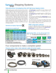
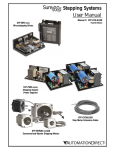
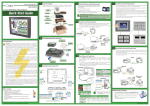
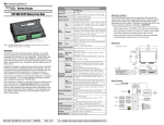
SURESTEP™
ADVANCED
MICROSTEPPING DRIVES
CHAPTER
4
In This Chapter...
Features . . . . . . . . . . . . . . . . . . . . . . . . . . . . . . . . . . . . . . .4–2
Specifications . . . . . . . . . . . . . . . . . . . . . . . . . . . . . . . . . . .4–3
Typical Wiring Diagram . . . . . . . . . . . . . . . . . . . . . . . . . . . .4–4
Connection Locations & Pin-out . . . . . . . . . . . . . . . . . . . . .4–4
Connecting the Motor . . . . . . . . . . . . . . . . . . . . . . . . . . . .4–5
Connecting the Power Supply . . . . . . . . . . . . . . . . . . . . . . .4–6
Connecting the I/O . . . . . . . . . . . . . . . . . . . . . . . . . . . . . . .4–7
SureStep™ Drive Digital Inputs . . . . . . . . . . . . . . . . . . . . . . . . .4–7
Connecting STEP and DIR to 5V TTL Logic . . . . . . . . . . . . . . . .4–7
Connecting STEP and DIR to Logic Other Than 5V TTL Level . . .4–8
Connections to the EN Input . . . . . . . . . . . . . . . . . . . . . . . . . . .4–9
Connecting the Analog Input . . . . . . . . . . . . . . . . . . . . . . . . .4–10
Connecting the Digital Output . . . . . . . . . . . . . . . . . . . . . . . .4–10
Drive Configuration . . . . . . . . . . . . . . . . . . . . . . . . . . . . . .4–11
SureStep™ Pro Software . . . . . . . . . . . . . . . . . . . . . . . . . .4–13
Choosing a Power Supply . . . . . . . . . . . . . . . . . . . . . . . . .4–16
Mounting the Drive . . . . . . . . . . . . . . . . . . . . . . . . . . . . .4–17
Dimensions and Mounting Slot Locations . . . . . . . . . . . . .4–17
Chapter 4: SureStep™ Advanced Microstepping Drives
Features
• Max 5A, 48V and max 10A, 80V models available
• Software configurable
• Programmable microsteps
• Internal indexer (via ASCII commands)
• Self test feature
• Idle current reduction
• Anti-resonance
• Torque ripple smoothing
• Step, analog, & serial communication inputs
4–2
SureStepTM Stepping Systems User Manual
Fourth Edition
12/2012
Chapter 4: SureStep™ Advanced Microstepping Drives
Specifications
SureStep™ Series Specifications – Microstepping Drives
Microstepping Drive
Drive Type
Output Current
Input Voltage
(external p/s required)
Configuration Method
Amplifier Type
Current Control
STP-DRV-4850
Protection
over-voltage, under-voltage, over-temperature,
external output faults (phase-to-phase & phase-to-ground), inter-amplifier shorts
Recommended Input Fusing
Fuse: 4A 3AG delay (ADC #MDL4)
Fuse Holder: ADC #DN-F6L110
Input Circuit
Step/Pulse
Input
Signals Direction
Enable
Analog
Output Signal
Communication Interface
Non-volatile Memory Storage
Idle Current Reduction
Microstep Resolution
Modes of Operation
Phase Current Setting
Features Self Test
Additional Features
Connectors
Maximum Humidity
Storage Temperature
Operating Temperature
Drive Cooling Method
Mounting
Dimensions
Weight
Agency Approvals
Fourth Edition
12/2012
STP-DRV-80100
Advanced microstepping drive with pulse or analog input, serial communication, & indexing capability
0.1–5.0 A/phase (in 0.01A increments)
0.1–10.0 A/phase (in 0.01A increments)
24–48 VDC (nominal) (range: 18-53 VDC)
24–80 VDC (nominal) (range: 18-88 VDC)
SureStep Pro software (included)
MOSFET, dual H-bridge, 4-quadrant
4-state PWM @ 20 kHz
Fuse: 6.25A 3AG delay (ADC #MDL6-25)
Fuse Holder: ADC #DN-F6L110
Opto-coupler input with 5 to 15 mA input current;
Logic Low is input pulled to 0.8 VDC or less; Logic High is input 4 VDC or higher.
optically isolated, differential, 5V, 330Ω;
min pulse width = 250 ns
max pulse frequency = 2MHz
adjustable bandwidth digital noise rejection feature
FUNCTIONS: step & direction, CW/CCW step, A/B quadrature, run/stop & direction, jog CW/CCW,
CW/CCW limits
optically isolated, 5–12V, 680Ω;
FUNCTIONS: motor enable, alarm reset, speed select (oscillator mode)
Range: 0–5 VDC; Resolution: 12 bit; FUNCTION: speed control
optically isolated, 24V, 10 mA max; FUNCTIONS: fault, motion, tach
RS-232; RJ11 (6P4C) receptacle
Configurations are saved in FLASH memory on-board the DSP.
reduction range of 0–90% of running current after delay selectable in ms
software selectable from 200 to 51200 steps/rev in increments of 2 steps/rev
pulse (step) & direction, CW/CCW, A/B quadrature, velocity (oscillator), SCL serial commands
0.1–5.0 A/phase (in 0.01A increments)
0.1–10.0 A/phase (in 0.01A increments)
checks internal & external power supply voltages, diagnoses open motor phases
Anti-resonance (Electronic Damping)
Auto setup
Serial Command Language (SCL) Host Control
Step Smoothing Filter (Command Signal Smoothing & Microstep Emulation)
Waveform (Torque Ripple) Smoothing
Communication: RJ11 (6P4C); Other: removable screw terminal blocks
90% non-condensing
-20–80 °C [-4–176 °F] (mount to suitable heat sink)
0–55 °C [32–158 °F] (mount to suitable heat sink)
natural convection (mount to suitable heat sink)
#6 mounting screws (mount to suitable heat sink)
3.0 x 3.65 x 1.125 inches [76.2 x 92.7 x 28.6 mm]
8 oz [227g] (approximate)
CE, RoHS
SureStepTM Stepping Systems User Manual
4–3
Chapter 4: SureStep™ Advanced Microstepping Drives
Typical Wiring Diagram
Logic Motor
Power Power
5VDC xx VDC
Step Motor
Power Supply
SureStep Typical
Wiring Diagram
–
VDC +
+
VDC –
A+
A–
STPDRV-xxxx
B+
STP-PWR-xxxx
B–
Cable Color Code
Term Wire Pin #
A+
Red
1
A– White
2
B+ Green 3
B– Black
4
Stepper Drive
Extension Cable 12" Motor Pigtail
with Connector
with Connector
STP-EXT(H)-020
Step Motor
STP-MTR(H)-xxxxx
Connection Locations & Pin-out
Removable
Terminals:
ELVP06100
햾 – EN햿 – EN+
헀 – DIR헁 – DIR+
헂 – STEP헃 – STEP+
Ground Terminal
(not visible)
ELVP05100
햸 – GND
햹 – AIN
햺 – +5V
햻 – Out햽 – Out+
ELFP06210
햲 – V+ (Power)
햳 – V- (GND)
햴 – A+ (Motor)
햵 – A- (Motor)
햶 – B+ (Motor)
햷 – B- (Motor)
Removable
Terminal Blocks
For Wiring
Status
LEDs
RS-232
Communication
Interface
Terminal block part #s (shown) are
Amphenol PCD (www.amphenolpcd.com)
RS-232 Comm Port:
(RJ11 6P4C)
햶 – RX
햵 – no connection
햴 – TX
햳 – GND
4–4
External wiring is connected using three separate
pluggable screw terminal connectors. The power
connections share a six position connector, the
digital inputs share another six position connector,
and the analog input and digital output share a five
position connector.
SureStepTM Stepping Systems User Manual
Fourth Edition
12/2012
Chapter 4: SureStep™ Advanced Microstepping Drives
Connecting the Motor
Warning: When connecting a step motor to a SureStep™ advanced microstepping
drive, be sure that the motor power supply is switched off. When using a motor not
supplied by AutomationDirect, secure any unused motor leads so that they can't
short out to anything. Never disconnect the motor while the drive is powered up.
Never connect motor leads to ground or to a power supply. (See the Typical Wiring
Diagram shown in this chapter for the step motor lead color code of
AutomationDirect supplied motors.)
Four lead motors
Four lead motors can only be connected one way, as shown below.
A+
A–
Red
4
lead
motor
White
Green
Black
B+
B–
4 Leads
All AutomationDirect SureStep™ motors are four lead bipolar step motors.
Six lead motors
Six lead motors can be connected in series or center tap. Motors produce more
torque at low speeds in series configuration, but cannot run as fast as in the center
tap configuration. In series operation, the motor should be operated at 30% less
than rated current to prevent overheating.
Grn/Wht
A–
n/c
A+
A–
6
lead
motor
White
A+
Green
n/c
Red
Black
B–
n/c
Red/
Wht
B+
6 Leads Series Connected
Grn/Wht
6
lead
motor
White
Green
Red
Black
B–
B+
Red/
Wht
n/c
6 Leads Center Tap Connected
Step motor wire lead colors vary from one manufacturer to another.
Fourth Edition
12/2012
SureStepTM Stepping Systems User Manual
4–5
Chapter 4: SureStep™ Advanced Microstepping Drives
Eight lead motors
Eight lead motors can also be connected in two ways: series or parallel. Series
operation gives you more torque at low speeds, but less torque at high speeds.
When using series connection, the motor should be operated at 30% less than the
rated current to prevent over heating. Parallel operation allows greater torque at
high speeds. When using parallel connection, the current can be increased by
30% above rated current. Care should be taken in either case to assure the motor
does not being overheat.
Orange
A+
Blk/
Wht
Orange
A+
Org/Wht
8
lead
motor
Blk/Wht
A–
8
lead
motor
Org/
Wht
A–
Black
Black
Red
Red/
Wht
B+
Yel/
Wht
Yellow
Red
Yellow
B–
B+
8 Leads Series Connected
Yel/
Wht
Red/
Wht B–
8 Leads Parallel Connected
Step motor wire lead colors vary from one manufacturer to another.
Connecting the Power Supply
An STP-PWR-xxxx power supply from AutomationDirect is the best choice to
power the step motor drive. If you need information about choosing a different
power supply, refer to the section entitled “Choosing a Power Supply” in this
chapter.
If your power supply does not have a fuse on the output or some kind of short
circuit current limiting feature, you need a fuse between the drive and the power
supply. Install the fuse on the + power supply lead.
+
Fuse *
VDC
–
Step Motor –
Power Supply
+
VDC
* External fuse not req'd when using an
STP-PWR-xxxx P/S; fuse is internal.
Warning: Connect the motor power supply "+" terminal to the drive "+ VDC"
terminal, and connect the power supply "–" terminal to the drive "VDC–" terminal.
Use wire no smaller than 18 gauge, and be careful not to reverse the wires.
Reverse connection will destroy your drive and void the warranty.
4–6
SureStepTM Stepping Systems User Manual
Fourth Edition
12/2012
Chapter 4: SureStep™ Advanced Microstepping Drives
Connecting the I/O
SureStep™ Drive Digital Inputs
The SureStep advanced drives include two high speed 5V digital inputs (STEP and
DIR), and one standard speed 5-12V input (EN).
Internal to the
STP-DRV-xxxx
330액
STEP+
220pF
STEP–
330액
DIR+
220pF
DIR–
680액
EN+
The digital inputs are optically isolated to
reduce electrical noise problems. There is
no electrical connection between the
control and power circuits within the
drive, and input signal communication
between the two circuits is achieved by
infrared light. Externally, the drive’s motor
power and control circuits should be
supplied from separate sources, such as
from a step motor power supply with
separate power and logic outputs.
For bidirectional rotation, supply a source
of step pulses to the drive at the STEP+
and STEP– terminals, and a directional
signal at the DIR+ and DIR– terminals.
EN–
Drive Digital Input Circuit
The ENABLE input allows the logic to turn off the current to the step motor by
providing a signal to the EN+ and EN– terminals. The EN+ and EN– terminal can
be left unconnected if the enable function is not required.
All logic inputs can be controlled by a DC output signal that is either sinking
(NPN), sourcing (PNP), or differential.
Connecting STEP and DIR to 5V TTL Logic
Connecting to an Indexer with Sinking Outputs
+5V OUT
Indexer
with
Sinking
Outputs
DIR
DIR+
DIR–
STP-DRV-xxxx
Drive
STEP+
EN+
STEP–
EN–
N/C
STEP
N/C
Connecting to an Indexer with Sourcing Outputs
Indexer
with
Sourcing
Outputs
COM
DIR–
DIR
DIR+
STP-DRV-xxxx
Drive
STEP–
EN+
STEP+
EN–
N/C
STEP
N/C
Fourth Edition
12/2012
SureStepTM Stepping Systems User Manual
4–7
Chapter 4: SureStep™ Advanced Microstepping Drives
Connecting to an Indexer with Differential Outputs
DIR+
DIR+
Indexer
DIR–
with
Differential
Outputs STEP+
DIR–
STP-DRV-xxxx
Drive
STEP+
EN+
STEP–
EN–
N/C
STEP–
N/C
Many high speed indexers have differential outputs.
Wiring for Encoder Following
Master
Encoder
A+
X1/STEP+
A–
X1/STEP–
B+
X2/DIR+
EN+
B–
X2/DIR–
EN–
STP-DRV-xxxx
Drive
N/C
N/C
Connecting STEP and DIR to Logic Other Than 5V TTL Level
Some step and direction signals, especially those of PLCs, don't use 5 volt logic.
You can connect signal levels as high as 24 volts to a SureStep advanced drive if
you add external dropping resistors to the STEP, DIR and EN inputs.
• For 12V logic, use 820Ω, 1/4W resistors
• For 24V logic, use 2200Ω, 1/4W resistors
Most PLCs can use 24 VDC Logic.
Warning: 5VDC is the maximum voltage that can be applied directly to a high speed
input (STEP and DIR). If using a higher voltage power source, install resistors to
reduce the voltage at the inputs. Do NOT apply an AC voltage to an input terminal.
Connecting to an Indexer with Sink or Source 12-24 VDC Outputs
DIR+
+12-24V
Indexer
with
Sinking
Outputs
ENABLE
STP-DRV-xxxx
DIR–
Drive
DIR
R
STEP
R
R
4–8
STEP+
EN+
STEP–
EN–
Indexer
with
Sourcing
Outputs
ENABLE
(If enable function is used)
SureStepTM Stepping Systems User Manual
COM
DIR–
DIR
DIR+
R
STEP
R
R
STP-DRV-xxxx
Drive
STEP–
EN–
STEP+
EN+
(If enable function is used)
Fourth Edition
12/2012
Chapter 4: SureStep™ Advanced Microstepping Drives
Connecting to a PLC with Sink or Source 12-24 VDC Outputs
–
+
PLC
with
Sinking
Outputs
ENABLE
DIR+
+12-24V
STP-DRV-xxxx
DIR–
Drive
DIR
R
STEP
STEP+
R
R
–
+
+12-24V 12 - 24 VDC
COM
PLC
with
Sourcing
Outputs
EN+
STEP–
COM
EN–
ENABLE
12-24 VDC
DIR–
DIR+
DIR
R
R
STEP
R
(If enable function is used)
STP-DRV-xxxx
Drive
STEP–
EN–
STEP+
EN+
(If enable function is used)
Connecting to Mechanical Switches at 24 VDC
+
DIR+
direction switch
+24VDC
Power
Supply
run/stop switch
(closed = run)
-
DIR-
2200액
STEP+
STP
-DRV
-xxxx
Drive
STEP-
2200액
Connections to the EN Input
The ENABLE input allows the user to turn off the current to the motor by providing
a 5-12 VDC positive voltage between EN+ and EN-. The logic circuitry continues
to operate, so the drive "remembers" the step position even when the amplifiers
are disabled. However, the motor may move slightly when the current is removed
depending on the exact motor and load characteristics.
Warning: 12VDC is the maximum voltage that can be applied directly to the
standard speed EN input. If using a higher voltage power source, install resistors to
reduce the voltage at the input. Do NOT apply an AC voltage to an input terminal.
Connecting ENABLE Input to Relay or Switch
+
5-12VDC
Power
Supply
EN+
switch or relay
(closed = logic low)
-
STP-DRV-xxxx
Drive
EN-
Connecting ENABLE Input to NPN Proximity Sensor
+
5-12VDC
Power
Supply
Fourth Edition
12/2012
EN+
+
-
output
NPN
Proximity
Sensor
EN-
STP-DRV-xxxx
Drive
SureStepTM Stepping Systems User Manual
4–9
Chapter 4: SureStep™ Advanced Microstepping Drives
Connecting ENABLE Input to PNP Proximity Sensor
+
+
5-12VDC
Power
Supply
-
-
EN+
output
PNP
Proximity
Sensor
STP-DRV-xxxx
Drive
EN-
Leave the ENABLE input unconnected if you do not need to disable the amplifiers.
Connecting the Analog Input
The SureStep advanced drives have one 0-5 VDC analog input.
Connecting AI to Analog Signal
0-5V signal
STP-DRV-xxxx
Drive
Internal to the
STP-DRV-xxxx
+5V
+5VDC, 10mA max
330액
AIN
220pF
AIN
signal return
GND
Connecting AI to Potentiometer
+5V
GND
Drive Analog Input Circuit
1-10k액
potentiometer
AIN
GND
STP
-DRV
-xxxx
Drive
Warning: The analog input is NOT optically isolated, and must be used with care.
It may operate improperly and it can be damaged if the system grounds are not
compatible.
Connecting the Digital Output
The SureStep advanced drives have one digital output that has separate + and terminals, and can be used to sink or source current.
Connecting DO to Inductive Load
relay coil
(inductive load)
Internal to the
STP-DRV-xxxx
OUT+
OUT–
Drive Digital Output Circuit
4–10
+
OUT+
STP-DRVxxxx Drive
OUT-
SureStepTM Stepping Systems User Manual
1N4935
suppression
diode
5-24 VDC
Power
Supply
-
Fourth Edition
12/2012
Chapter 4: SureStep™ Advanced Microstepping Drives
Connecting DO as Sinking Output
+
Load
OUT+
5-24 VDC
Power
Supply
STP-DRVxxxx Drive
Connecting DO as Sourcing Output
5-24 VDC
Power
Supply
STP-DRVxxxx Drive
-
OUT-
+
OUT+
OUT-
Load
-
Warning: Do NOT connect the digital output to a voltage greater than 30 VDC.
The current through each DO terminal must not exceed 10 mA.
Drive Configuration
You need to configure your drive for your particular application before using the
drive for the first time. The SureStep advanced microstepping drives include a CD
containing SureStep™ Pro drive configuration software for this purpose. The
software contains instructions for installation on a PC, and instructions for
configuring the drives. Configuration settings include:
• drive model
• motor characteristics
• motion control mode
• I/O configuration
Anti-Resonance / Electronic Damping
Step motor systems have a tendency to resonate at certain speeds. SureStep
advanced drives automatically calculate the system’s natural resonate frequency,
and apply damping to the control algorithm. This greatly improves midrange
stability, allows higher speeds and greater torque utilization, and improves settling
times.
This feature is on by default, but it can be turned off using the “Motor...” icon of
the SureStep Pro software.
Idle Current Reduction
This feature reduces current consumption while the system is idle, and
subsequently reduces drive and motor heating. However, reducing the idle
current also reduces the holding torque.
The percent and delay time of the idle current reduction can be adjusted using the
“Motor...” icon of the SureStep Pro software.
Microstep Resolution
The microstep resolution (steps/rev) can be selected using the “Motion & I/O...”
icon of the SureStep Pro software, and selecting “Pulse and Direction Mode”.
Fourth Edition
12/2012
SureStepTM Stepping Systems User Manual
4–11
Chapter 4: SureStep™ Advanced Microstepping Drives
Modes of Operation
Modes of operation are selectable via the SureStep Pro software “Motion & I/O...”
icon.
• Pulse & Direction Mode
• Pulse & Direction
• CW & CCW Pulse
• A/B Quadrature
• Velocity (Oscillator) Mode
• Serial Command Language (SCL)
Phase Current Setting
Motor phase current settings are available through the SureStep Pro software
“Motor...” icon and the “Running Current” settings.
Serial Command Language (SCL) Host Control
SureStep advanced drives can accept serial commands from a host PC or PLC.
This feature can be selected using the “Motion & I/O...” icon of the SureStep Pro
software, and selecting Serial Command Language.
Step Smoothing Filter (Command Signal Smoothing & Microstep Emulation)
The Step Smoothing Filter setting is effective only in the Step (Pulse) & Direction
mode. It includes command signal smoothing and microstep emulation to soften
the effect of immediate changes in velocity and direction, therefore making the
motion of the motor less jerky. An added advantage is that it can reduce the wear
on mechanical components.
This feature can be modified by using the “Motion & I/O...” icon of the SureStep
Pro software, and selecting “Pulse and Direction Mode”.
Waveform (Torque Ripple) Smoothing
All step motors have an inherent low speed torque ripple that can affect the
motion of the motor. SureStep advanced drives can analyze this torque ripple and
apply a negative harmonic to negate this effect. This feature gives the motor much
smoother motion at low speeds.
This feature is on by default, and is factory preset for standard motors. It can be
turned off or on using the “Motor...” icon of the SureStep Pro software. To set
Waveform Smoothing for custom motors, select “Define Custom Motor...” and the
“Waveform Smoothing” “Wizard...”.
4–12
SureStepTM Stepping Systems User Manual
Fourth Edition
12/2012
Chapter 4: SureStep™ Advanced Microstepping Drives
SureStep™ Pro Software
The SureStep advanced drives STP-DRV-4850 & -80100 are configured using
SureStep Pro™ configuration software, which is included on CD with the drive.
The software is divided into two major sections, “Motion and I/O” and “Motor”
configuration. There are also communication settings, drive selection, and drive
status features.
• Runs on Windows 98, 2000, ME, NT, Vista, XP.
Complete software instructions are included in the “Help” files within the software.
Communication:
Upload and Download from/to the drive. When you connect to a drive, the
Motor, Motion Mode, and Dedicated I/O settings that are currently in the drive
will appear on the right of the screen (as will the Drive and Revision at the top of
the screen). “Upload from Drive” to get all the configuration settings from the
drive or “Download to Drive” to apply all the settings on the PC to the drive.
Fourth Edition
12/2012
SureStepTM Stepping Systems User Manual
4–13
Chapter 4: SureStep™ Advanced Microstepping Drives
Motor Configuration:
Clicking on the “Motor..” icon will bring up the motor configuration screen. You
can choose a motor from the pull-down menu or enter a custom motor (you will
need to enter that motor’s specific information). If you know the inertia mismatch
of the load, you should enter it. If the inertia mismatch is unknown, this entry can
be left at 1. The idle current is default at 50%. Idle current should be used unless
the application will require a constant high holding torque
Motion and I/O:
Selecting this tab will allow you to set the drive’s mode of operation.
• Pulse and Direction:
Used with high-speed pulse inputs (CW/CCW,
Pulse/Direction, Quadrature) generated from a PLC,
encoder, etc.
• Velocity (Oscillator):
Allows the drive to be speed controlled by an analog
signal. The input is 0 – 5V and can be scaled to the
desired maximum speed. Bidirectional motion can
be attained by changing the Offset (under “Advanced
Analog Settings”) to a non-zero value. EX: Setting
this value to 2500mV will command the drive to be
at zero speed when 2.5V are present.
• Serial Command Language (SCL):
Causes the drive to respond to serial commands. A
PLC or PC can issue a variety of commands to
enable simple motion, gearing/following, turn on the
output, wait for an input, etc. See the “SCL Manual”
under the SureStep Pro Help menu. Serial
commands can be tested by selecting the “Drive”
pull-down menu from the menu bar, and then
selecting “SCL Terminal”.
4–14
SureStepTM Stepping Systems User Manual
Fourth Edition
12/2012
Chapter 4: SureStep™ Advanced Microstepping Drives
Drive Pull-down Menu:
This software menu gives you several features to monitor and test the drive.
• Alarm History – Will read back the most recent drive faults
• Clear Alarm – Will clear the current drive fault.
• Restore Factory Defaults – resets the drive to “out of the box” status.
• SCL Terminal – Allows SCL commands to be tested by typing them in.
(HyperTerminal is NOT a good tool for serial commands, because the drive will
“time-out” if you use HyperTerminal to enter strings. SCL Terminal will send the
entire string at once.)
• Self-Test – Rotates the motor clockwise and counterclockwise.
(Tests motor and cabling)
• Status Monitor – Shows the current Drive and I/O status.
• Set Quick Decel Rate – Used when the drive encounters faults or overtravel
limits.
Fourth Edition
12/2012
SureStepTM Stepping Systems User Manual
4–15
Chapter 4: SureStep™ Advanced Microstepping Drives
Choosing a Power Supply
Voltage
Chopper drives work by switching the voltage to the motor terminals on and off
while monitoring current to achieve a precise level of phase current. To do this
efficiently and silently, you'll want to have a power supply with a voltage rating at
least five times that of the motor. Depending on how fast you want to run the
motor, you may need even more voltage. Generally, more is better; the upper
limit being the maximum voltage rating of the drive itself.
If you choose an unregulated power supply, do not allow the “no load” voltage to
exceed the maximum voltage rating of the drive. Unregulated supplies are rated
at full load current. At lesser loads, such as when the motor is not moving, the
actual voltage can be up to 1.4 times the voltage list on the power supply label.
The STP-PWR-xxxx power supplies are designed to provide maximum voltage
while under load, without exceeding the drive’s upper voltage limit when
unloaded.
Use the “...Recommended Component Compatibilty” chart in the “Chapter 1:
Getting Started” to select the appropriate SureStep power supplies for use with
SureStep drives.
Current
The maximum supply current you will need is the sum of the two phase currents.
However, you will generally need a lot less than that, depending on the motor
type, voltage, speed and load conditions. That's because the SureStep drives use
switching amplifiers, converting a high voltage and low current into lower voltage
and higher current. The more the power supply voltage exceeds the motor
voltage, the less current you'll need from the power supply.
We recommend the following selection procedure:
1. If you plan to use only a few drives, choose a power supply with at least twice
the rated phase current of the motor.
2. If you are designing for mass production and must minimize cost, get one power
supply with more than twice the rated current of the motor. Install the motor in
the application and monitor the current coming out of the power supply and into
the drive at various motor loads. This test will tell you how much current you
really need so you can design in a lower cost power supply.
If you plan to use a regulated power supply, you may encounter a problem with
current foldback. When you first power up your drive, the full current of both
motor phases will be drawn for a few milliseconds while the stator field is being
established. After that, the amplifiers start chopping and much less current is
drawn from the power supply. If your power supply thinks this initial surge is a
short circuit it may "foldback" to a lower voltage. With many foldback schemes
the voltage returns to normal only after the first motor step and is fine thereafter.
In that sense, unregulated power supplies are better. They are also less expensive.
SureStep™ STP-PWR-xxxx power supplies from AutomationDirect are the best choices
of DC power supply to use with SureStep™ STP-DRV-xxxx microstepping drives.
4–16
SureStepTM Stepping Systems User Manual
Fourth Edition
12/2012
Chapter 4: SureStep™ Advanced Microstepping Drives
Mounting the Drive
You can mount your drive on the wide or the narrow side of the chassis using #6
screws. Since the drive amplifiers generate heat, the drive should be securely
fastened to a smooth, flat metal surface that will help conduct heat away from the
chassis. If this is not possible, then forced airflow from a fan may be required to
prevent the drive from overheating.
• Never use your drive in a space where there is no air flow or where the ambient
temperature exceeds 40 °C (104 °F).
• When mouting multiple STP-DRV-xxxx drives near each other, maintain at least
one half inch of space between drives.
• Never put the drive where it can get wet.
• Never allow metal or other conductive particles near the drive.
Dimensions and Mounting Slot Locations
0.61
[15.5]
1.98
[50.3]
SureStep
Microstepping
Drive
STP-DRV-4850
STP-DRV-80100
3.39 [86.1]
3.0
[76.2]
1.125
[28.6]
3.65 [92.7]
6X slot 0.16 [4.1]
wide, full R
0.663
[16.8]
Fourth Edition
12/2012
DIMENSIONS
= in [mm]
SureStepTM Stepping Systems User Manual
4–17
Chapter 4: SureStep™ Advanced Microstepping Drives
BLANK
PAGE
4–18
SureStepTM Stepping Systems User Manual
Fourth Edition
12/2012