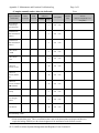
1
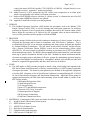
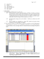
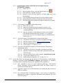
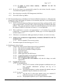
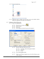
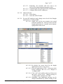
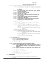
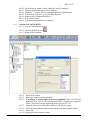
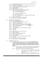
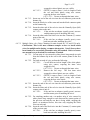
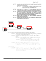
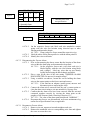
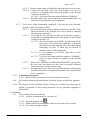
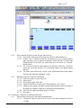
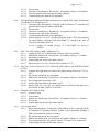
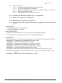
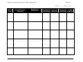
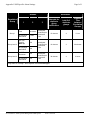
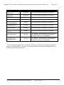
Page 1 of 17 TITLE: SOP FOR ALARM SYSTEMS MANAGEMENT AND RESPONSE CHAPTER: 2-Facility SOP #: SF-2-4.04 Issue Date: Effective Date: SUPERSEDES SOP #: N/A AUTHORED BY: ____________________________________ DATE: Indiana CTSI SSF Director QA APPROCAL: DATE: Quality Compliance Specialist 1. REVISION Significant changes incorporated in this version include: 1.1. Modified Signatory Approval Section 1.2. Updated applicable graphics and icons to reflect new version of Siemens Insight software. Updated Appendix B accordingly. 1.3. Extensively revised Section 6.2 to clarify the procedure for acknowledging alarms and to incorporate the remote desktop feature as an option for logging into the IUPUIR3BIO alarm computer. 1.4. Added Section 6.3 to incorporate responses to BLN (internet) disconnections and field panel transmission failure notifications. Updated Appendices C, F, and H accordingly. 1.5. Updated Section 6.4.1 to include the restart of RENO when making system modifications. 1.6. Modified Section 6.4.3.1.7 in order to clarify when to use each access level. 1.7. Added Section 6.4.3.1.9 for assigning access levels to Insight applications. 1.8. Extensively revised Section 6.4.3.2 to reflect procedural modifications for setting up an administrator on the IUPUIR3BIO computer. 1.9. Added Section 6.4.3.4 for directives on how to remove an administrator from the IUPUIR3BIO computer. 1.10. Modified Sections 6.4.7.1 and 6.4.7.2 to include a disclaimer on wiring units and to specify locations where the referred directives are applicable. 1.11. Added Section 6.4.7.3 to incorporate freezer wiring directives in the additional locations of the SSF Annex and the CTSL labs. 1.12. Modified Section 6.4.7.5 to incorporate the use of signage when a unit has been unalarmed, to remove Section 6.4.7.5.4, and to add verification directives for the dis-alarming of a unit 1.13. Updated Section 6.4.7.6 for the addition of verification directives when re-alarming a unit. 1.14. Added Section 6.4.7.7 to provide directives for alarm function verification if a unit has been repaired, defrosted, or moved to a new location. 1.15. Clarify Section 6.4.8 to describe that this service is provided by a skilled Siemens technician. 1.16. Modified Section 6.5.2 to add that, alternately, a system report may be ran to confirm the presence or absence of alarms for any given day. 1.17. Updated Section 6.6 to add annual verifications for receiving a notification if internet connectivity is lost and if field panel transmission is interrupted. Also, updated to add testing SF-2-4.04 SOP for Alarm Systems Management and Response Page 2 of 17 a unit in the annex (MS B-46) and the CTSL (UH5030 or UH5049). Original directives were modified for clarity. Appendix C updated accordingly. 1.18. Added Section 6.6.10 to incorporate the SSF Annex room temperature as an alarm point which is not applicable to the annual verification procedure. 1.19. Replaced 2008 ISBER reference with that of “current version” to eliminate the need for SOP revision when ISBER Best Practices are updated. 1.20. Appendix E modified to include year and pagination. 2. PURPOSE 2.1. This Standard Operating Procedure (SOP) defines the procedures used in the Indiana CTSI Sample Storage Facility (SSF) to set the alarming and notification parameters for notifying personnel in response to out-of-specification conditions detected by the Siemens alarm system and to define the procedure to be followed by SSF personnel when an alarm notification is received. This procedure satisfies guidance set forth in ISBER 3. PRINCIPLE 3.1. Specimen storage facilities must provide continuous monitoring of critical systems in order to safeguard the specimens and to remain in compliance with “Best Practice” guidances. This is accomplished in the SSF via an electronic monitoring and alarm system designed and installed by Siemens Building Technologies. The SSF alarm system utilizes Siemens’ Insight software with a Remote Notification Option (RENO) system and an acknowledging system called APOGEE Go. All active alarms are identified according to parameters set by SSF in the RENO alarm management console. The RENO Alarm transmits alarm notifications for each individual alarm tag to specific destinations defined by the SSF. Methods for alarm notification include electronic messaging, pagers and phones. Effective systems for maintaining specimen integrity also require that changes are incorporated by a thoughtful, defined, and recorded procedure and alarms are responded to appropriately and, thus, these must also be defined. 4. SCOPE 4.1. The SOP applies to SSF personnel assigned to install wiring, acknowledge and respond to the SSF alarm system notifications and, as directly communicated to via SSF Personnel, applicable investigator personnel. The alarm set point parameters are defined in the applicable equipment or facility SOP. Response to Out of Specification Conditions is managed through SF-1-10 SOP for Out of Specification Response and Notification Management. Applicable alarm points for equipment monitored by the SSF alarm and monitoring system located within or outside of the SSF Facility include: * Mechanical Refrigeration Units * Liquid Nitrogen Freezers * Low Oxygen Alarm * Room C135 and MS-B046 temperature * Electronic LN2 “Stop” Activation * Uninterrupted Power Supplies BLN Network Connections Field Panel Transmission Error 5. MATERIALS (Components of the system are further described in Appendix A) 5.1. Insight Advanced Workstation Alarm System 5.2. RENO Software System 5.3. APOGEE Go Software System 5.4. High Speed Trunk Interface 5.5. Computer and related equipment 5.6. UPS in rooms C158B and C135 SF-2-4.04 SOP for Alarm Systems Management and Response Page 3 of 17 5.7. 5.8. 5.9. 5.10. 5.11. 5.12. Screw Driver Sharpie Tape, electrical Labels for alarm lines Wire, 18 gauge Wire Cutters 6. PROCEDURE 6.1. Management of SSF Personnel “on-call” status 6.1.1. SSF Personnel are “on-call” from approximately 5:30 PM to 7:00 AM on work days and 24 hrs on days SSF personnel are not scheduled to work and as needed to provide 24 hour/7 day per week coverage. If the on-call person is unable to respond it is the responsibility of this person to notify the director or, if unable to reach the director, notify other SSF staff to arrange for alarm response to be covered. 6.1.2. SSF Management manages the on-call schedule. Conflicts are referred to the SSF Director. 6.1.3. On-call schedules are maintained on a shared SSF calendar and current contact information is listed in Appendix D (template). 6.2. SSF Personnel response to an alarm (Either in response to a page that is received displaying the call-back number of “274-2741” or to an email/phone message that is received stating that there is a point in alarm). Refer to the figure below as a reference for the screen display for points in alarm. 6.2.1. Acknowledge the Alarm as directed by one of the alarm notification methods or as defined below. NOTE: Acknowledging an Alarm confirms that you are responding per applicable SOPs! SF-2-4.04 SOP for Alarm Systems Management and Response Page 4 of 17 6.2.1.1. Acknowledging Alarms (APOGEE GO for Insight) from the IUPUIR3BIO computer. 6.2.1.1.1. Login per 6.4.2. 6.2.1.1.2. On the Insight software, select the Alarm Status icon. 6.2.1.1.3. Look under the A column for no bell. 6.2.1.1.4. Absence of the bell icon indicates an alarm point that is not acknowledged. 6.2.1.1.5. Left click on the alarm point that has not been acknowledged. 6.2.1.1.6. Acknowledge the alarm by selecting the bell icon on the top. 6.2.1.1.7. The alarm point resets and the bell reappears under the A column. 6.2.1.2. Call in using a telephone to acknowledge alarms. 6.2.1.2.1. Dial (317) 274-2741. 6.2.1.2.2. Enter user id and password (Assigned in section 6.4.5.6). 6.2.1.2.3. Follow prompts to listen and stop the Remote Notification escalation (RENO). 6.2.1.2.4. Once at a computer, acknowledge the alarm via accessing the IUPUIR3BIO computer directly (Section 6.2.1.1), remotely (Section 6.2.1.4), or by accessing the Apogee Go Web Interface (Section 6.2.1.3). 6.2.1.3. Access the Apogee Go Web Interface to acknowledge alarms. 6.2.1.3.1. Log into the VPN for IU using the IU passphrase and login. 6.2.1.3.2. Enter the intranet website at http://iupuir3bio/insightgo 6.2.1.3.3. Enter the domain name as iupuir3bio. 6.2.1.3.4. Follow steps 6.2.1.1.2 thru 6.2.1.1.7. 6.2.1.4. Access the IUPUIR3BIO computer via Remote Desktop Connection to acknowledge alarms. 6.2.1.4.1. Log into the VPN for IU using the IU passphrase and login. 6.2.1.4.2. Open the “Remote Desktop Connection” program located in the START menu. 6.2.1.4.3. Enter the complete name of the computer: iupuir3bio.ads.iu.edu 6.2.1.4.4. Log in to the computer per 6.4.2. 6.2.1.4.5. Acknowledge the alarm per 6.2.1.1.2 thru 6.2.1.1.7. 6.2.2. Access the alarm log remotely per the Apogee Go Web interface or the Remote Desktop Connection to the IUPUIR3BIO computer and determine if a condition exists that requires immediate action per the applicable SOP (Appendix F) 6.2.2.1. Note: Appendix F serves as a quick reference guide only. Staff should consult applicable facility/equipment/OOS SOPs for further details on response to individual alarms. 6.2.2.2. Appendix F must be re-verified minimally each month and when referenced SOPs are modified. 6.2.2.3. If a referenced SOP is modified, prepare a new version of Appendix F indicating any changes in applicable information and noting the new SOP version in Section 1. SF-2-4.04 SOP for Alarm Systems Management and Response Page 5 of 17 6.2.2.4. If unable to access alarm remotely – REPORT TO SSF TO INVESTIGATE. 6.2.3. Review the Alarm Log (automatically printed for each alarm); describe response, record date/time/signature for response. 6.2.4. Have alarm log reviewed by SSF Management (initial/date). 6.2.5. File in SSF Alarm Log Binder. 6.3. SSF Personnel Response to a Building Level Network (BLN) disconnection or a field panel data transmission failure notification (In response to an immediate page that is received displaying the call-back number of “666”). 6.3.1. NOTE: A BLN disconnection/field panel transmission failure notification WILL NOT trigger an actual alarm; it will only send a system message that is included on the alarm printout. Thus, when personnel are alerted, the acknowledgement of an alarm and/or the stopping of RENO, as described in Section 6.2.1, are not applicable. 6.3.2. When notification is received, wait approximately 5 to 10 minutes for a possible reconnection. A reconnection is apparent if another page is received displaying the call-back number of “0.” 6.3.3. If the there is a reconnection within approximately 10 minutes, no action is necessary. 6.3.4. If there is no reconnection in approximately 10 minutes, REPORT TO SSF TO INVESTIGATE. 6.3.4.1. Refer to Appendix F for necessary actions. 6.3.5. Document response on the alarm log per 6.2.3-6.2.5. 6.4. Modifying the Alarm System: 6.4.1. Complete the Alarm System Change Approval Log (Appendix E) 6.4.1.1. Enter the date the change request is initiated. 6.4.1.2. Enter the type and details of change requested 6.4.1.3. Justify the request 6.4.1.4. Submit for Approval 6.4.1.5. Obtain approval by the SSF Director. 6.4.1.6. Complete the change per the applicable section below. 6.4.1.7. RESTART RENO per Section 6.4.4. 6.4.1.8. Have a different SSF staff member verify that the change was made appropriately. 6.4.2. Logging into the system. 6.4.2.1. As an administrator: 6.4.2.1.1. Enter your IU username, defined passphrase established when you were provided administrator privileges and log on to IUPUIR3BIO. 6.4.2.1.2. The defined passphrase is neither automatically updated with your standard IU log-in credentials nor can it be reset. 6.4.2.2. As an user: 6.4.2.2.1. Log onto the IU ADS logon domain using your standard IU credentials (username and current IU passphrase). 6.4.2.2.2. The passphrase updates as your IU login credentials update. SF-2-4.04 SOP for Alarm Systems Management and Response Page 6 of 17 6.4.2.3. Select the Insight Icon. 6.4.2.4. Application opens to display the alarm status screen as the default with the toolbar (See Appendix B for toolbar icon definitions). 6.4.3. Setting up or deactivating a user. 6.4.3.1. Log in as an administrator. 6.4.3.1.1. 6.4.3.1.2. 6.4.3.1.3. 6.4.3.1.4. Select the user account icon. Select Account. Select New. Select Insight Account and a pop up screen appears. 6.4.3.1.5. Enter the following in the pop up screen: 6.4.3.1.5.1. User name, same as the login for Outlook. 6.4.3.1.5.2. Full Name. 6.4.3.1.5.3. Initials. 6.4.3.1.6. Leave default graphics blank. 6.4.3.1.7. Under Access Groups, assign the access level for all objects as one of the following: SF-2-4.04 SOP for Alarm Systems Management and Response Page 7 of 17 6.4.3.1.7.1. Read-Only (for non-SSF staff who wish to be involved for remote notification purposes only). 6.4.3.1.7.2. Command (non-SSF staff approved by management). 6.4.3.1.7.3. Configure/Edit (for SSF employees). 6.4.3.1.8. Under Preference: 6.4.3.1.8.1. Select Name. 6.4.3.1.8.2. Select the APPLY button. 6.4.3.1.9. For new SSF employees only, change access levels for all Insight applications to “Configure/Edit”: 6.4.3.1.9.1. Single click on the new username just created from the username list. The access levels for the Insight applications are viewable on the bottomright portion of the screen. 6.4.3.1.9.2. By default, the access levels for the Insight applications are set to “No Access.” 6.4.3.1.9.3. Select all applications (CTRL + left mouse click) having privileges that are to be changed to “Configure/Edit.” 6.4.3.1.9.4. Click “edit” in the toolbar at the top of the screen and select “access levels.” Change privilege to “Configure/Edit” and then click “OK.” 6.4.3.1.9.5. Alternately, each application privilege can be changed individually by double clicking on the SF-2-4.04 SOP for Alarm Systems Management and Response Page 8 of 17 application and changing the privilege. 6.4.3.2. To Set up an administrator on the IUPUIR3BIO computer: 6.4.3.2.1. Current administrators may perform this function by logging in using administrator credentials. Current administrators are listed on Appendix I. 6.4.3.2.2. From the start button, select control panel, system, advanced, user profiles and settings. 6.4.3.2.3. Select the “click here” hyperlink. 6.4.3.2.4. Select the “Users” folder. 6.4.3.2.5. Click on “Action” in the toolbar at the top of the screen, then select “New User.” 6.4.3.2.6. Fill out username, full name, and leave description blank. 6.4.3.2.7. Assign password and confirm. 6.4.3.2.8. Uncheck the box “User must change password at next login” and check the box “Password never expires.” 6.4.3.2.9. Click “Create” 6.4.3.2.10. Double click on the newly created member’s name and select the “Member of” tab. 6.4.3.2.11. Select “Add.” Add the following profiles: Administrators, Apogee Users, Distributed COM Users, Remote Desktop Users, and Users. 6.4.3.2.11.1. To select these profiles, select “advanced” and then “find now.” 6.4.3.2.12. Select OK, and then “apply.” 6.4.3.2.13. Remove password protect setting from account: 6.4.3.2.13.1.From the start button, select control panel, display, screen saver. 6.4.3.2.13.2.Uncheck the box that states, “On resume, password protect”. 6.4.3.2.13.3.Click “Apply” and then “OK.” 6.4.3.3. Deactivating a User 6.4.3.3.1. Log in as an administrator or user. 6.4.3.3.2. Right click on user account name. 6.4.3.3.3. Select delete account. 6.4.3.3.4. Select OK. 6.4.3.4. To Remove an administrator from the IUPUIR3BIO computer: 6.4.3.4.1. Current administrators may perform this function by logging in using administrator credentials. Current administrators are listed on Appendix I. 6.4.3.4.2. From the start button, select control panel, system, advanced, user profiles and settings. 6.4.3.4.3. Select the “click here” hyperlink. 6.4.3.4.4. Select the “Users” folder. 6.4.3.4.5. Right click on the user that is to be removed. 6.4.3.4.6. Click on delete and confirm deletion. 6.4.4. Restart RENO 6.4.4.1. This section must be performed by a user logged in with administrator privileges. SF-2-4.04 SOP for Alarm Systems Management and Response Page 9 of 17 6.4.4.2. 6.4.4.3. 6.4.4.4. 6.4.4.5. 6.4.4.6. 6.4.4.7. 6.4.4.8. 6.4.5. On the Siemens Alarm Console, right click on My Computer. From the options that appear select “Manage.” Select the “+” next to Services and Applications to expand the tree. Left click on “Services” to view the drop down list. Right click on “Insight RENOServer.” Left click on restart. Wait until information box is completed. Creating New Staff in RENO. 6.4.5.1. Log in as administrator or user. 6.4.5.2. Click on the RENO icon. 6.4.5.3. Right click on contacts. 6.4.5.4. 6.4.5.5. 6.4.5.6. Select New Contact. Enter new contact’s name and initials. If privileges to acknowledge alarms are permitted, enter a user ID and password. Note that the ID and password MUST contain only numerical values. If privileges are not permitted, proceed to step 6.4.5.10 6.4.5.7. Check the box next to Allow this Contact to call into the system. 6.4.5.8. Select the items that should be heard when the user calls in to the system. 6.4.5.9. Select OK. 6.4.5.10. Right click on the contact’s name. SF-2-4.04 SOP for Alarm Systems Management and Response Page 10 of 17 6.4.5.11. 6.4.5.12. 6.4.5.13. 6.4.5.14. 6.4.5.15. 6.4.5.16. 6.4.5.17. Set up each device that needs to be utilized as a notification device. Select OK once completed. Repeat for each additional device (cell phone, pager, email, etc.) To edit a device right click on the device. Select properties. Make changes and select OK. Add new user to any groups that are applicable. 6.4.5.17.1. Right click on group name. 6.4.5.17.2. Select Add Member. 6.4.5.17.3. Enter a * in the Name field. 6.4.5.17.4. Select Find Now. 6.4.5.17.5. Left click on the device name that needs to be added. 6.4.5.17.6. Select OK. 6.4.5.18. Repeat to add as many devices as needed. 6.4.5.19. Restart Reno to activate modifications. 6.4.6. Creating a New Escalation List 6.4.6.1. Log in as administrator or user. 6.4.6.2. Right click on Escalation List. Refer to point 6.4.6.3. Select New Escalation List. 6.4.6.4. Enter a name for this escalation list in the name field. 6.4.6.5. Complete the Emergency box by selecting the button. 6.4.6.6. Enter a * in the Name field. 6.4.6.7. Select Find Now. 6.4.6.8. Left click on the device name that needs to be added. 6.4.6.9. Select OK. 6.4.6.10. Select OK. 6.4.6.11. Right click on new escalation list name. 6.4.6.12. Select insert stage. 6.4.6.13. Change field Type to Contact Group. 6.4.6.14. Enter a * in the Name field. 6.4.6.15. Select Find Now. 6.4.6.16. Left click on the group name that needs to be added. 6.4.6.17. Select OK. 6.4.6.18. Repeat until escalation list is complete. 6.4.6.19. Restart Reno to activate modifications. 6.4.7. Installation of alarm wires 6.4.7.1. One Unit (for units located in C135 and C156 only). Clarification: This is the most common example on how to install alarm wires for one unit. Not all freezers have been found to be successfully alarmable using this method. Refer to freezer user manual or a professional for assistance as needed. 6.4.7.1.1. Cut one strip of wire encased in white plastic long enough to reach from the banana clip in the wall to the contact points on the unit. 6.4.7.1.2. For both cut ends of wire, perform the following: 6.4.7.1.2.1. Cut off about an inch in length of the white plastic using wire cutters, exposing the inner wires wrapped in foil. 6.4.7.1.2.1.1. Do not cut through the inner wires. 6.4.7.1.2.2. Remove the foil wrap. The four inner wires SF-2-4.04 SOP for Alarm Systems Management and Response Page 11 of 17 wrapped in colored plastic are now visible. GENTLY remove about ½ inch in length of both the red and black plastic using wire cutters, exposing the bare wires inside. 6.4.7.1.2.3.1. Do not cut through the inner wires. 6.4.7.1.3. Insert one end of the red wire into the red connector point on the banana clip. 6.4.7.1.4. Insert the black wire of the same end into the black connector point on the banana clip. 6.4.7.1.5. Insert the other end of the red wire into the Normally Open (NO) contact point on the unit. 6.4.7.1.5.1. If the unit has an adapter (usually green), unscrew and disconnect prior to installing the wires. 6.4.7.1.6. Insert the other end of the black wire into the Common (C) contact point of the unit. 6.4.7.1.6.1. If the unit has an adapter (usually green), screw back into unit after installing the wires. 6.4.7.2. Multiple Units, a.k.a. Daisy Chaining (for units located in C135 and C156 only). Clarification: This is the most common example on how to install alarm wires for multiple units sharing a common alarm point. Not all freezers have been found to be successfully alarmable using this method. Refer to freezer user manual or a professional for assistance as needed. 6.4.7.2.1. Cut one strip of wire encased in white plastic long enough to reach from the banana clip in the wall to the contact points on the first unit. 6.4.7.2.2. For both cut ends of wire, perform the following: 6.4.7.2.2.1. Cut off about an inch in length of the white plastic using wire cutters, exposing the inner wires wrapped in foil. 6.4.7.2.2.1.1. Do not cut through the inner wires. 6.4.7.2.2.2. Remove the foil wrap. The four inner wires wrapped in colored plastic are now visible. 6.4.7.2.2.3. GENTLY remove about ½ inch in length of both the red and black plastic using wire cutters, exposing the bare wires inside. 6.4.7.2.2.3.1. Do not cut through the inner wires. 6.4.7.2.3. Insert the end of the red wire into the red connector point on the banana clip. 6.4.7.2.4. Insert the other end of the red wire into the Normally Open (NO) contact point of unit #1. 6.4.7.2.4.1. If the unit has an adapter (usually green), unscrew and disconnect prior to installing the wires. 6.4.7.2.5. For attaching another unit, cut another strip of wire encased in white plastic long enough to reach between the contact points of the previous unit and the one that is being added, stripping the plastic as mentioned before, this time only stripping the black wires on each end. 6.4.7.2.6. Insert the end of the black wire into the Common (C) contact point of the previous unit. 6.4.7.2.6.1. If the unit has an adapter (usually green), screw back into unit after installing the wires. 6.4.7.1.2.3. SF-2-4.04 SOP for Alarm Systems Management and Response Page 12 of 17 6.4.7.2.7. Insert the other end of the black wire into the Normally Open (NO) contact point of the next unit. 6.4.7.2.7.1. If the unit has an adapter (usually green), screw back into unit after installing the wires. 6.4.7.2.8. Repeat steps 6.4.7.2.5 thru 6.4.7.2.7 (using additional white wires) as necessary until all units are alarmed. Then proceed to next step. 6.4.7.2.9. When there are no more units to add to the daisy chain, cut a final strip of wire encased in white plastic long enough to reach in between the contact points of the final unit and the banana clip in the wall, stripping only the black wires on both ends. 6.4.7.2.10. Insert an end of the black wire into the Normally Open (NO) contact point of the final unit. 6.4.7.2.11. Insert the other end of the black wire into the black connector point on the banana clip (See Figure 1). Figure 1 Freezer 1 NO C Freezer 2 NO C Freezer 3 NO C Red Black 6.4.7.3. One unit (for units located in MS B-46, UH5030, and UH5049). 6.4.7.3.1. Alarm point wires having a blue plastic casing have been pre-installed in the wall by Campus Facility Services. 6.4.7.3.2. Each blue wire contains only 2 wires, encased in white and black plastic. 6.4.7.3.2.1. Strip off the blue, white, and black colored casings of the end of the wire per 6.4.7.1.2. 6.4.7.3.2.2. Attach one wire to the Normally Open (NO) and the other to the Common (C) contact points on the unit. 6.4.7.3.3. The method of “Daisy Chaining” units is not necessary in these locations due to the fact that there were enough alarm points/wires installed for the maximum number of units that the room can hold. 6.4.7.4. Labeling the wires 6.4.7.4.1. On the back of the respective unit, a diagram indicates each of the numbered wire slots available for connections. See Figure 2 and 3 for the most common diagrams. SF-2-4.04 SOP for Alarm Systems Management and Response Page 13 of 17 Wire Slot Diagram Figure 2 X X 1 2 3 4* 5* 6* x x * Indicates slots with no specification 1 = Normally Open 2 = Common 3 = Normally Closed Figure 3 6.4.7.4.2. 6.4.7.4.3. 6.4.7.4.4. Wire Slot Diagram 7 6 5 4* 7= Normally Open 6= Common 5= Normally Closed 3* 2* 1* On the respective freezer unit, label each wire attached to contact points with the wire slot location using electrical tape or other labeling medium and a sharpie. 6.4.7.4.2.1. Wrap each piece of tape around the respective wire. Label the white or blue alarm point wire with the alarm point ID. Identify the wires on all units. 6.4.7.5. Disconnecting the Freezer Alarm 6.4.7.5.1. Prior to disconnecting the alarm, ensure that the location of the alarm wires within the alarm plug are documented as described: 6.4.7.5.1.1. On the respective freezer unit, verify that each wire is labeled legibly with the wire slot location using labels and a sharpie. Label any wires that are not already legibly labeled using the black sharpie and labels. 6.4.7.5.2. Place a sign on the door of the unit stating “FREEZER ALARM DISCONNECTED: Do not use for sample storage” 6.4.7.5.3. Using a suitable screwdriver, loosen the screws holding the alarm wires to the contact points on the freezer unit and remove. 6.4.7.5.3.1. If the unit has an adapter (usually green) unscrew and disconnect prior to removing the wires. 6.4.7.5.4. Connect the alarm wires removed from the unit’s contact points to close the alarm circuit using a wire nut suitable for 18 gauge wire. 6.4.7.5.5. Confirm that the alarm wires have been removed from the unit and connected together correctly by viewing the alarm point on the graphics of the Siemens Alarm Console per Section 6.5.1. 6.4.7.5.5.1. The value of the alarm point should read “NORMAL.” 6.4.7.5.6. Document that freezer was disconnected on freezer maintenance log and/or Out of Specification Form, as applicable. 6.4.7.6. Reconnect to Freezer Alarm 6.4.7.6.1. Remove wire nut, separate wires and straighten each wire. 6.4.7.6.2. Reinsert the numbered wires to corresponding wire slots and tighten the screw to secure the wires. SF-2-4.04 SOP for Alarm Systems Management and Response Page 14 of 17 6.4.7.6.3. 6.4.7.6.4. 6.4.7.6.5. Reinsert alarm adapter (if applicable) and tighten the screws to secure. Confirm that the alarm wires have been hooked up to the unit correctly by viewing the alarm point on the graphics of the Siemens Console per Section 6.5.1. 6.4.7.6.4.1. The value of the alarm point should read “NORMAL.” Document that freezer was reconnected on freezer maintenance log and/or Out of Specification Form, as applicable. 6.4.7.7. Test Freezer Alarm Functionality (applicable if the unit has been defrosted, repaired, or moved to another location). 6.4.7.7.1. Place unit in alarm by using the alarm test function on the unit. If the alarm test function is not available, force unit in alarm by changing unit temperature parameters. 6.4.7.7.2. Verify that the unit will send an alarm to the Siemens system by viewing the corresponding alarm point on the graphics of the Siemens Console per Section 6.5.1. 6.4.7.7.2.1. The value should read “ALARM.” Record actions on the freezer log, or the OOS form if applicable, to document that alarm is activated when the unit exceeds the assigned temperature set point. If alarm does not function as intended, report to SSF Management. 6.4.7.7.2.2. If unit parameters were altered, return them to their previous settings. 6.4.7.7.2.3. Verify that the alarm point has returned to “NORMAL” status by again viewing the graphics on the Siemens Console. 6.4.7.7.3. Remove the “FREEZER ALARM DISCONNECTED” signage from the unit’s door once alarm wires have been successfully connected and unit has been verified to send an alarm. 6.4.7.7.4. Document that freezer alarm was tested and functions within normal parameters on the freezer maintenance log and/or Out of Specification Form, as applicable. 6.4.8. Activating an alarm point 6.4.8.1. Notify Seimens representative for new alarm point activation. 6.4.9. SSF Siemens Alarm Notification Schema: Escalation Groups are defined in Appendix G. 6.4.10. SSF Siemens Alarm Escalation Schema: Settings for escalation per alarm type are defined in Appendix H (Note: alarm parameters are per applicable equipment or facility SOP) 6.5. Monitoring 6.5.1. To view alarm points for monitoring. 6.5.1.1. Log in as an administrator or a user per 6.4.2. 6.5.1.2. Select the graphics icon. 6.5.1.3. Double click on the room number in the tree where the point is located. 6.5.1.4. Read value on graphics display. SF-2-4.04 SOP for Alarm Systems Management and Response Page 15 of 17 6.5.2. Daily, monitor the alarm system for any alarm activity. 6.5.2.1. Tear off the alarm print-off from the previous day, initial and date it. 6.5.2.2. If there were no alarms for that day, document on a piece of alarm printer paper that there were no alarms for that day, initial and date it. Ensure that documentation lists all dates for which there were no alarms (i.e weekend, holiday dates). 6.5.2.3. If it is discovered that an alarm printout was missed a certain day, an activity report may be ran per Section 6.5.3 to determine if there were alarms during that time. 6.5.2.4. File alarm print-offs/activity reports in the OOS/Alarms/Deviations binder located in the Operations Manager’s office. 6.5.3. Running a report for a specific alarm point: 6.5.3.1. Select the System Activity Log icon. 6.5.3.2. Select Query. 6.5.3.3. Select Query again, then Add. 6.5.3.4. Under the Find Now section, in the Type dropdown, select object. 6.5.3.5. Another screen appears and then select the alarm point(s) (select all points if in response to running a report for a missed daily alarm printout).. 6.5.3.6. Enter the date range (maximum range is 30 days). 6.5.3.7. Run report. 6.6. Verification – Annual or as otherwise indicated. 6.6.1. BLN (internet connectivity) disconnection notification. 6.6.1.1. Unplug the internet cable from the back of the alarm computer located in C158B. SF-2-4.04 SOP for Alarm Systems Management and Response Page 16 of 17 6.6.1.2. 6.6.1.3. 6.6.1.4. 6.6.1.5. Record time. Monitor for Notification. Record time. Acceptable if delay is <10 minutes. Plug the internet cable back into the alarm computer. Acknowledging the alarm is not applicable. 6.6.2. Field panel data transmission failure notification for both the SSF Annex (Field Panel #2) and the CTSL (Field Panel #3). 6.6.2.1. Disconnect the cable labeled “Network Cable Field Panel #2” from the field panel located in the SSF Annex (MS B-46). 6.6.2.2. Record time. 6.6.2.3. Monitor for Notification. Record time. Acceptable if delay is <10 minutes. 6.6.2.4. Reconnect the cable to the field panel. 6.6.2.5. Acknowledging the alarm is not applicable. 6.6.2.6. Repeat Steps 6.6.2.2-6.6.2.5 for the field panel of the CTSL, disconnecting the cable labeled “Network Cable Field Panel #3” located in the AOC of University Hospital (UH5033). 6.6.2.6.1. Contact IU Health Security at 317-944-8000 for access to UH5033. 6.6.3. UPS: Test UPS Alarm for both C158B and C135. 6.6.3.1. Unplug the UPS in C158B from the electrical outlet. Record time. 6.6.3.2. Monitor for Notification. Record Time. Acceptable if delay is <3 minutes. 6.6.3.3. Reconnect to main power. 6.6.3.4. Acknowledge the alarm in the alarm system. 6.6.3.5. Repeat Steps 6.6.3.1-6.6.3.4 for the UPS located in C135. 6.6.4. Ultra Low Freezer Alarm for C135, MS B-46 (SSF Annex), and UH5030/UH5049 (CTSL). 6.6.4.1. Program the high alarm set point of an empty backup freezer in C135 to 85ºC. 6.6.4.2. Record time when unit goes into alarm. 6.6.4.3. Monitor for Notification. Record Time. Acceptable if delay is <20 minutes. 6.6.4.4. Re-set high alarm set point to -60ºC. 6.6.4.5. Acknowledge the alarm in the alarm system. 6.6.4.6. Repeat Steps 6.6.4.1-6.6.4.5 for a unit located in MS B-46 and again for a unit located in either UH5030 or UH5049. 6.6.5. Emergency LN2 Stop (E-Stop) 6.6.5.1. Activate E-stop. 6.6.5.2. Record time. 6.6.5.3. Monitor for Notification. Record Time. Acceptable if delay is <3 minutes. 6.6.5.4. Re-activate. 6.6.5.5. Acknowledge the alarm in the alarm system. 6.6.6. Low Oxygen Alarm 6.6.6.1. Reset alarm set points A1-Adj and A2-Adj both to 20.9% on the unit (Refer to PointGard II Operating Manual located in the Operations Manager’s Office for instructions on how to do this). 6.6.6.2. Record time when unit goes into alarm. 6.6.6.3. Monitor for Notification. Record Time. Acceptable if delay is <3 minutes. 6.6.6.4. Re-set alarm points A1-Adj and A2-Adj to 19.5% and 19.0%, respectively. 6.6.6.5. Acknowledge the alarm in the alarm system. SF-2-4.04 SOP for Alarm Systems Management and Response Page 17 of 17 6.6.7. LN2 Freezer Alarm 6.6.7.1. Activate the alarm test feature on an SSF LN2 unit. 6.6.7.2. Record time when unit goes into alarm. 6.6.7.3. Monitor for Notification. Record Time. Acceptable if delay is <20 minutes. 6.6.7.4. Reset the alarm on the freezer. 6.6.7.5. Acknowledge the alarm in the alarm system. 6.6.8. Refrigerator and standard mechanical freezer: Not Applicable 6.6.9. Room C135 Temperature: Not Applicable 6.6.10. Room MS B-46 Temperature: Not Applicable 6.6.11. Record all actions and results for Alarm testing on Appendix C and attach alarm log printout. 7. REFERENCES 7.1. ISBER Best Practices (current version) 7.2. Siemens Insight Rev 3.1.1 DVD 8. DOCUMENTATION 8.1. Records are maintained per SF-1-6 Controlled Document Management SOP. 8.2. All Deviations are managed per the SF-1-9 Deviation Management SOP. 9. APPENDICES The current version of each of the following appendices is used to guide and/or implement this SOP: APPENDIX A: Components of the Insight Alarm System (1 Page) APPENDIX B: Toolbar icons and descriptions (1 Page) APPENDIX C: Maintenance and Function Verification Log (1 Page) APPENDIX D: SSF Alarm Call Personnel Log (Template) (1 Page) APPENDIX E: Siemens Alarm System Change Approval Log (1 Page) APPENDIX F: SSF Siemens Alarm Response Guide (1 Page) APPENDIX G: SSF Siemens Alarm Notification Schema: Escalation Group Design (1 Page) APPENDIX H: SSF Siemens Alarm Escalation Schema: Settings for Escalation per Alarm Type (1 Page) APPENDIX I: Siemens Alarm Console Administrators (1 Page). SF-2-4.04 SOP for Alarm Systems Management and Response Appendix A Page 1of 1 Components of the Insight Alarm System Software Systems: 1.1. Insight Advanced Workstation 1.1.1. Graphical approach to manage and control a building from an easy to use interface. 1.1.1.1. Collect, view, analyze trend information. 1.1.1.2. Store and retrieve long term information. 1.1.2. RENO (Remote Notification Option) 1.1.2.1. Permits user to configure level of detail in the alarm messages sent to each contact person. 1.1.2.2. Permits user to define group notifications. 1.1.2.3. Permits user to define escalation lists for notification. 1.1.3. APOGEE GO (Remote Acknowledging Option) 1.1.3.1. Allows users control and access to Insight information via the internet. 1.1.3.2. Permits users to configure who can view notification points. 1.1.4. High Speed Trunk Interface 1.1.4.1. Interfaces the serial data line to the APOGEE GO Automation System. SF-2-4 SOP for Alarm Systems Management and Response Form Version 02 Appendix B Toolbar Icons and Descriptions SF-2-4 SOP for Alarm Systems Management and Response Form Version 03 Page 1 of 1 Appendix C: Maintenance and Function Verification Log Page 1 of 1 (Complete annually and as otherwise indicated) Type of Alarm or Notification Time Activated Time Notified Difference (Minutes) Actual Year: Acceptable Limit BLN (internet connectivity) disconnection* <1 Yes No Field Panel #2 data transmission failure* <1 Yes No Field Panel #3 data transmission failure* <1 Yes No UPS - Room C158B <3 Yes No UPS - Room C135 <3 Yes No Ultra-Low Freezer (C135) < 20 Yes No Ultra-Low Freezer (MS B46) < 20 Yes No Ultra-Low Freezer (UH5030 OR UH5049) < 20 Yes No E-Stop <3 Yes No Low Oxygen Alarm <3 Yes No LN2 Freezer < 20 Yes No Initials/ Date Comments / Corrective Actions (must be completed if not acceptable) Reviewed By /Date: *Not an actual alarm point. This is a notification that is sent to the alarm printer and pagers and does not require the halting of RENO, nor the acknowledgment of the notification on the Siemens console. SF-2-4 SOP for Alarm Systems Management and Response Form Version 04 Appendix D: Alarm Call Personnel Log Template Name Email Page # Page 1 of 1 Cell Number Other Template Effective Date: __________ Obsolete Date: __________ SF-2-4 SOP for Alarm Systems Management and Response Form Version 02 Appendix E Siemens Alarm System Change Approval Log Page 1of 1 Year__________ Page ____of ____ Request Initiation Date Description of SSF Alarm Modification Requested Rationale for Modification Request Submitted Initials/Date SF-2-4 SOP for Alarm Systems Management and Response Form Version 03 Request Approved Initials/Date Request Change Completed Verified Initials/Date Initial/Date Appendix F SSF Siemens Alarm Response Guide Page 1of 1 SOP Verification (do not exceed 1 Month) YEAR: ________________ SF-2-1 Mechanical Refrigeration Unit Storage Room version SF-2-2 LN2 System and Freezer Room Operations version SF-3-1 Mechanical Refrigeration Units version SF-3-2 LN2 Freezers version Verified By (initials and date) Alarm Point Mechanical Freezer (Ultra Low) Mechanical Freezer (Standard) Refrigerator Value ALARM ALARM Activated Activated Report to SSF and determine cause. ALARM Room Temperature – C135 and MS-B046 ALARM E-Stop Activation Alarm Computer on Battery Power (UPS) BLN Disconnect* Field panel data transmission failure* Report to SSF Refer to SOP SF- 3-1 and 1-10 Appendix D. Report to SSF Refer to SOP SF- 3-1 and 1-10 Appendix D. Report to SSF Refer to SOP SF- 3-2 and 1-10 Appendix D. Contact CFS Report to SSF if not resolved Refer to SOP SF-2-1 Report to SSF, manually close the main LN2 valve or press E-Stop, and notify SSF Director Refer to SOP SF-2-2 Report to SSF and determine cause. Refer to SOP SF-2-2 ALARM Liquid Nitrogen Freezer Low Oxygen Monitor Expected Response Report to SSF Refer to SOP SF- 3-1 and 1-10 Appendix D. ALARM Disconnected: >~10 minutes have passed without a notification that the BLN has been reconnected (Notification per Section 6.3 of this SOP). Field Panel Failure: >~10 minutes have passed without a notification that the BLN has been reconnected (Notification per Section 6.3 of this SOP). Report to SSF. Confirm all equipment is within normal parameters. Restart Siemens Alarm Computer. If this is ineffective in re-establishing a connection, contact the Siemens tech on call (1-800-832-6569) Report to SSF. Confirm all equipment is within normal parameters. Restart Siemens Alarm Computer. If this is ineffective in re-establishing a connection, contact the Siemens tech on call (1-800-832-6569) Reviewed by: *Not an actual alarm point. This is a notification that is sent to the alarm printer and pagers and does not require the halting of RENO, nor the acknowledgment of the notification on the Siemens console. SF-2-4 SOP for Alarm Systems Management and Response Form Version 04 Appendix G SSF Specific Alarm Settings Page 1of 1 Actions Escalation Group 1 On- Call Tech All SSF personnel Phone/pager Notification E-mail On- Call Tech & Back-up N/A Phone/pager Notification N/A All SSF Personnel N/A Group Level 3 Phone/pager Notification 3 Intervals for duplicate group notification total # of duplicate groups Elapsed Time between Escalation Groups Investigator Personnel per Submission Form 15 minutes 4 1 hour Investigator Personnel per Submission Form 10 minutes 3 30 minutes Investigator Personnel per Submission Form 30 minutes 4 2 hours 2 Group 1 Group Level 2 Escalation N/A Loop back to Group 1 and Repeat until acknowledged SF-2-4 SOP for Alarm Systems Management and Response Form Version 02 Appendix H: SSF Siemens Alarm Escalation Schema: Settings for Escalation Per Alarm Type Alarm Point Mechanical Freezer (Ultra Low) Mechanical Freezer (Standard) Alarm Delay Page 1of 1 Notification 15 minutes Per Current Version of Appendix G of this SOP 15 minutes Per Current Version of Appendix G of this SOP Refrigerator 15 minutes Per Current Version of Appendix G of this SOP Liquid Nitrogen Freezer 15 minutes Per Current Version of Appendix G of this SOP Room Temperature: C-135 and MS B-46 1 hour Per Current Version of Appendix G of this SOP Low Oxygen Monitor 1 minute Per Current Version of Appendix G of this SOP E-Stop Activation 1 minute Per Current Version of Appendix G of this SOP Uninterrupted Power Supplies 1 minute Per Current Version of Appendix G of this SOP BLN Disconnection* No delay No escalation. Notification sent to alarm printer and on-call pagers only. Notification of reconnection is sent when connection is re-established. Field panel data transmission failure* No delay No escalation. Notification sent to alarm printer and on-call pagers only. Notification of reconnection is sent when connection is re-established. *Not an actual alarm point. This is a notification sent to the alarm printer and pagers and does not require the halting of RENO since there is no escalation schema, nor the acknowledgement of the notification on the Siemens console. SF-2-4 SOP for Alarm Systems Management and Response Form Version 04 Appendix I: Siemens Alarm Console Administrators Page 1of 1 Current Administrators for the Siemens Alarm Console Name Position Effective Date: Obsolete Date: SF-2-4 SOP for Alarm Systems Management and Response Form Version 02