1
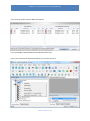
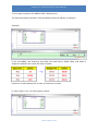
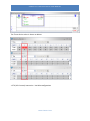
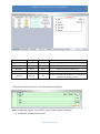
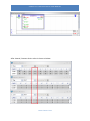
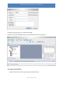
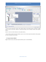
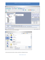
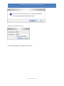
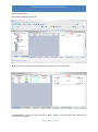
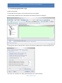
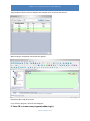
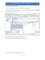
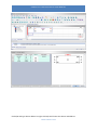
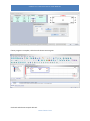
CIMON PLC FUNCTION BLOCK USER MANUAL CIMON PLC Function Block - User Manual - Version : 20150609 WWW.CIMON.COM CIMON PLC FUNCTION BLOCK USER MANUAL 1. SPECIFICATION 1.1. Function Block Specification Items Project Description Remark Max. registered FB 128 User Library Max. used FB Up to CPU memory Language IL / LD Name Max. 32 characters Password Max. 16 characters Password Hint Max. 40 characters Program Capacity 512 steps Description Max. 64 characters 128 FB Maximum Number Input + I/O: 64 Output + I/O : 64 Local Variable : 896Word Name Max. 16 characters Description Max. 16 characters Variable CICON Version PLC CPU Local Variable : Z Dev. Version 6.00 or higher Multiple FB Version 6.00 or higher Multiple FB used Single FB All version Only single FB used • Unless it is Multiple FB, IO variable number will be limited up to 32. 1.2. Required CPU for Function Block (FB Type : Single / Multiple) Series CM1 CM2 CM3 CPU FB Multiple FB XPnA O X XPnB O O CPnA~D O X BP O X PLCS O O Micro-S O O • In order to use FB in CP series, CPU version must be 4.43 or higher. • The multiple Function Blocks are supported in CPU firmware version 6.00 or higher version. • Multiple FB : You can use multiple Function Blocks on one Rung. WWW.CIMON.COM CIMON PLC FUNCTION BLOCK USER MANUAL 1.3. Size of Function Block 1.3.1 Function Block Download option If you use Function Blocks in scan program, the size of project file will be increased according device, variable and description. The Function Block is added in project file when program is complied. Therefore, the step size of project file can be different with downloading steps into PLC. In order to save PLC memory, “FB information” Full Download is disable in CICON Option menu. You may save 50%~80% size with this in general. (If you want to download full information of FBs to CPU module, choose “FB information” Full Download.) • In case of Full Download, below data will be downloaded to CPU module. Function Block information - Name / Password / Hint / Description Function Block Variable – Variable name / IO / Type / Device / Description Scan program for Function Block WWW.CIMON.COM CIMON PLC FUNCTION BLOCK USER MANUAL Etc. 2~3Step • In case of NOT Full Download, below data will be downloaded to CPU module. Function Block information - Password Function Block Variable – IO / Type / Device Scan program for Function Block Etc. 2~3Step 1.3.2 Function Block Upload When you upload program from PLC to CICON, your opened project file in CICON has the same function blocks with uploaded function blocks. If not, uploaded function blocks will have different variable name and description. • If project file has the same FB with uploaded project. - If time stamp is the same, the same function blocks are uploaded. - If time stamp is different, you can overwrite uploaded function blocks to project file. WWW.CIMON.COM CIMON PLC FUNCTION BLOCK USER MANUAL If you click Yes, below Function Block list appears. If you click Replace FB, uploaded Function Block will be used. Even if you overwrite wrong function blocks, you can still recover it. WWW.CIMON.COM CIMON PLC FUNCTION BLOCK USER MANUAL Right-click function block and choose Recovery FB(R) and choose the function block you want to recovery. 1.4. Function Block L Device If you create Function Block, 16Word(256bit) is assigned to L device address automatically. Therefore, user cannot use those L address in other scan program. Series CPU XP1A XP2A Input (64Bit) Output (64Bit) Monitoring L984.0 ~ L987.F L988.0 ~ L991.F L992.0 ~ L999.F L112.0 ~ L115.F L116.0 ~ L119.F L120.0 ~ L127.F L984.0 ~ L987.F L988.0 ~ L991.F L992.0 ~ L999.F L48.0 ~ L51.F L52.0 ~ L55.F L56.0 ~ L63.F L240.0 ~ L243.F L244.0 ~ L247.F L248.0 ~ L255.F XP3A CM1 CP3 CP4 XP1B XP2B XP3B CM2 CM3 BP PLCS PLCS Block 1.5. Limitation of Function Block Diagram in Use 1. Positive Transition-Sensing Contact and Negative Transition-Sensing Contact. If you use both elements in Function Block repeatedly, FB may not recognize them. Instead of Positive and Negative Transition-sensing contact, use Normally Open Contact as below. WWW.CIMON.COM CIMON PLC FUNCTION BLOCK USER MANUAL 2. Array type instruction (Ex: BMOV, DSFR, FIFW and etc.) The Input and Output variable in Function Block use device address in sequence. Example) If you use BMOV, you intend to send D10, D11 and D12 to D100, D101, and D102 in sequence. However, the result will show as below. D10 moves to D100, M100 moves to D101, and X30 moves to D102. In order to figure it out, use Index register as below. WWW.CIMON.COM CIMON PLC FUNCTION BLOCK USER MANUAL Write Offset value 10 to IN1 (D device) and make it index register (R0) to have value in sequence. 3. Timer and Counter If you want to use Timer or Counter in Function Block Diagram, Index Register (Offset R device) must be used. Timer and Counter Instruction (TON, CTU and etc.) only use Timer and Counter device. You can use Index register (R device) with below CPU type. CPU Type Firmware version PLCS Version 6.10 Micro-S Version 6.10 XPnB Version 6.10 XPnE All version CPnE All version WWW.CIMON.COM CIMON PLC FUNCTION BLOCK USER MANUAL • TON (On Delay Timer) Instruction : Variable configuration Variable Name I/O Type Device FLAG Input Bit Operating bit for ON Delay Timer OFFSET Input Word Write Index register number (0~15) SETTING Input Word OUTPUT Output Bit Write Timer set value (TS) (According to PLC parameter, 100ms / 10ms) It will be turned ON, if FLAG bit is remained ON in Setting time. - SETTING : If it is 100ms and you write 30, it will be 3second. • TON (On Delay Timer) Instruction : Function Block scan program Before using Index register, save OFFSET value in Index register (R device). WWW.CIMON.COM CIMON PLC FUNCTION BLOCK USER MANUAL 1) Set OFFSET variable value into R0 2) On Delay Timer is turned ON, Timer will be turned ON. 3) If it remains ON until assigned time at SETTING, OUTPUT will be turned ON. • Timer in Scan program If you use Timer in Function Block, F10(Application Instruction) is recommended to check ON Delay or OFF Delay. For example, if M00 bit is remained ON for 3 seconds (in case of 100ms timer), M10 bit will be turned ON. • Monitoring After a Function Block is downloaded to CPU and it is turned to RUN mode, the function block appears monitoring mode as below. Even though the function block is running, Timer will not work if M00 is OFF. M00 is turned ON and after 3 seconds (in case of 100ms), OUTPUT(M10) will be turned ON as below. WWW.CIMON.COM CIMON PLC FUNCTION BLOCK USER MANUAL The Timer device value is shown as below. • CTU (UP Counter) Instruction : Variable configuration WWW.CIMON.COM CIMON PLC FUNCTION BLOCK USER MANUAL Variable Name I/O Type Device FLAG Input Bit Operating bit for UP Counter OFFSET Input Word Write Index register number (0~15) SETTING Input Word Write Counter set value (CS) RESET Input Bit Counter reset bit OUTPUT Output Bit It will be turned ON, if FLAG bit is turned ON and OFF as Setting counter. -RESET : COUNTER is not cleared automatically. It must be cleared by RESET bit. • CTU (UP Counter) Instruction : Function Block scan program Before using Index register, save OFFSET value in Index register (R device). 1) Set OFFSET variable value into R0 WWW.CIMON.COM CIMON PLC FUNCTION BLOCK USER MANUAL 2) UP Counter is turned ON, Counter will be increased. (If RESET bit is ON, counter will be cleared) 3) If it is turned On and Off as assigned counter at SETTING, OUTPUT will be turned ON. • Counter in Scan program If you use Counter in Function Block, F10(Application Instruction) is recommended to check ON Delay or OFF Delay. For example, if M00 bit is turned On and Off 5times (5th ON time), M10 bit will be turned ON. • Monitoring After a Function Block is downloaded to CPU and it is turned to RUN mode, the function block appears monitoring mode as below. Even though the function block is running, Counter will not work if M00 is OFF. If M00 bit is turned On 5th time, OUTPUT (M10) will be turned ON. WWW.CIMON.COM CIMON PLC FUNCTION BLOCK USER MANUAL The Counter device value is shown as below. If RESET bit (M05) is turned ON, the counter value is cleared. WWW.CIMON.COM CIMON PLC FUNCTION BLOCK USER MANUAL After cleared, Counter device value is shown as below. WWW.CIMON.COM CIMON PLC FUNCTION BLOCK USER MANUAL 2. Create Function Block 2.1. Add new Function Block Create new project. If you want to use more than one Function Block on the same Rung, select FB Extension at the project Option and click OK. WWW.CIMON.COM CIMON PLC FUNCTION BLOCK USER MANUAL Click Function Block Window tab. Right-click the User Library and choose FB(A) • User Library : FB that you create is saved in this folder. You can edit, import and export FB. User Library is belong to project property so if you create new project or open other project, FB will be removed. If you want to use FB that you created at the other project, you can export FB to file or add it to User System Library. If FB in User Library is not used in Scan program, it will be removed when you download project file to PLC. Therefore, export FB to file before downloading project file to PLC. You can also find out deleted FB after uploading PLC to CICON. Click File and choose Import FB backup file. • System Library : This is fixed FB that Cimon provides. You are not able to edit FB in the System Library. • User System Library : If you export FB in User Library to File, you can save it in file or in User System Library. You are not able to edit FB in this folder but you can only delete FB. Type FB Name and click OK. If you want to lock the FB, type password and confirm it. Otherwise, just leave a blank at Password. WWW.CIMON.COM CIMON PLC FUNCTION BLOCK USER MANUAL Variable[?] and program[?] are created under FB002. Question mark [?] will disappear when you set Variable and create scan program. 2.2. Export Function Block Right-click the FB and choose Export FB (Function Block→File). WWW.CIMON.COM CIMON PLC FUNCTION BLOCK USER MANUAL • If you click Yes, FB will be saved in User System Library. User System Library is belong to CICON folder so even if you open a project or create new project, you can always use FB in User System Library. Notice : You are not able to edit FB in User System Library. • If you click No, FB will be saved to folder in your PC. You can also import this FB file to other project file. You can edit FB in User Library. 2.3. Import Function Block Right-click User Library and choose Import FB Library (File → Function Block). WWW.CIMON.COM CIMON PLC FUNCTION BLOCK USER MANUAL Choose the FB file(*.FBS) and click Open. If the same FB name exists in Library, click Yes to change the name. WWW.CIMON.COM CIMON PLC FUNCTION BLOCK USER MANUAL Type the new name and click OK. Function Block (FB005) is just added in User Library. WWW.CIMON.COM CIMON PLC FUNCTION BLOCK USER MANUAL 3. Function Block Variable WWW.CIMON.COM CIMON PLC FUNCTION BLOCK USER MANUAL Double-click Variable. FB Variable configuration pops up. ▶The variable in FB folder is local variable that only works in current FB folder. • Variable Name : The same name with FB or Device address cannot be used. The maximum 16 characters are available. WWW.CIMON.COM CIMON PLC FUNCTION BLOCK USER MANUAL • I/O : From I/O pull-down menu, choose Input, Output or Input/Output. - Input : Read integer value or device address - Output : Write device address only (Integer value is not possible) - I/O(Input and Output) : You can use one device address for both input or output. (Integer value is not possible) ▶ You cannot use below device type for Output and I/O. X / F/ T / TC / TS / C / CC / CS • Type : From Type pull-down menu, choose Bit, Word, Double Word or Float. - B (Bit) : 0 or 1 - W (Word) : 2Byte (Unsigned: 0~65,535 / Signed: -32,768~32,767) - DW (Double Word) : 4Byte (Unsigned: 0~4,294,967,295 / Signed: -2,147,483,648~2,147,483,647) - F (Float) : 4Byte (3..4E +/- 38 : 7Digits) • Device : You cannot set up device address here. When FB is used in scan program(Ladder Logic), you can set device address for each input and output. • Description : Maximum 16characters are available. Add Input : Default Variable name is IN + number that is persistent. 4. Function Block Program WWW.CIMON.COM CIMON PLC FUNCTION BLOCK USER MANUAL 4.1. Develop program(Ladder Logic) Double click Program. Function Block scan program is very similar with main scan program. Instead of END / PEND instruction, FB Program End will be used in FB scan program. To change the option of FB scan editor, click Tool and choose CICON Options and click FB Option tab. If you enter an instruction on a Rung, FB Variable pops up to select Variable. WWW.CIMON.COM CIMON PLC FUNCTION BLOCK USER MANUAL Type Variable or Device name or Double-click Variable name or Device and click OK. When a Rung is completed, red vertical line appears. Example) If IN1 is ON, OUT1 is ON. If you save the program, red mark will disappear. 5. Enter FB in a main scan program(Ladder Logic) WWW.CIMON.COM CIMON PLC FUNCTION BLOCK USER MANUAL 5.1. Enter FB in a Ladder Logic To enter FB in a Ladder Logic, click Project Window and add scan program. Click the desired location on the Rung where you want to enter FB and press Shift+F9 or click Function Block Diagram appears as below. Choose FB in User Library or System Library and click OK. If you click the FB name, detailed variable appears on FB Review. To set device address for FB variable, double-click FB. WWW.CIMON.COM . CIMON PLC FUNCTION BLOCK USER MANUAL Click N/D and type device address or right-click N/D and choose the device and address. WWW.CIMON.COM CIMON PLC FUNCTION BLOCK USER MANUAL If Scan program is complete, click File and choose Save Program. Click Tool and Choose Compile All+Link. WWW.CIMON.COM CIMON PLC FUNCTION BLOCK USER MANUAL Check Message Window in case of error. WWW.CIMON.COM