1
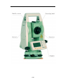
Thank you for choosing NTS02. As your handy construction tool, it will
provide you with the most efficient and economic solutions to your job. To
fully utilize the potential of your instrument and protect your investment,
you need to, as we strongly suggest, thoroughly read this manual before
starting any operations. Should you run into any problems, NWI’s technical
support team will be happy to assist you.
1/62
Contents
Contents ....................................................................................................... 2
1. Precautions for Safety ............................................................................ 4
1.1 NOTE ..................................................................................................... 4
1.2 Definition of Indication ........................................................................ 5
1.3 Safety Standards for Laser ( NTS02 series )....................................... 6
1.4 About User ............................................................................................. 7
1.5 Exceptions from Responsibility ........................................................... 7
2. Preparation before Measurement ......................................................... 8
2.1 About Battery ........................................................................................ 8
2.1.1 Battery Power Symbol ....................................................................... 8
2.1.2 Replace the Battery............................................................................ 9
2.1.3 Recharge the Battery ......................................................................... 9
2.2 Setting Up the Instrument.................................................................. 10
2.3 Centering and Levelling-Up............................................................... 10
3. Basic Functions ..................................................................................... 12
3.1 Nomenclature ...................................................................................... 12
3.2 Basic Key Operation ........................................................................... 14
3.3 Display ................................................................................................. 15
3.4 Mode Diagram .................................................................................... 15
3.5 Power On/Off ...................................................................................... 17
3.6 How to Input Number and Alphabet ................................................ 17
3.7 How to Configure ................................................................................ 18
4. Angle Measurement .............................................................................. 20
4.1 Measure a Horizontal Angle of Two Points ...................................... 20
4.2 Set the Horizontal Angle to a Required Value.................................. 20
5. Distance Measurement ......................................................................... 21
6. Coordinate Measurement .................................................................... 22
6.1 Input the Occupied Point Data .......................................................... 23
6.2 Azimuth Setting ................................................................................... 24
6.3 3D Coordinate Measurement ............................................................. 25
7. Setout Measurement ............................................................................. 26
7. 1 Distance Setout ................................................................................... 27
7.2 Coordinates Setout Measurement ..................................................... 28
8. Area ........................................................................................................ 30
8.1 Area Calculation by Measured Data or Input Data ........................ 30
9. Offset Measurement ............................................................................. 32
9.1 Distance Offset Measurement ............................................................ 32
9.2 Angle Offset Measurement................................................................. 34
2/62
9.3 Plane Offset Measurement ................................................................. 35
9.4 Column Offset Measurement ............................................................. 37
10. MLM .................................................................................................... 38
11. Height measurement (REM) .............................................................. 39
12. Intersection .......................................................................................... 42
13. Point Projection .................................................................................. 46
13.1 Define Baseline .................................................................................. 47
14. Inverse.................................................................................................. 48
15. Roadway .............................................................................................. 49
15.1 Define the Horizontal Curve of Roadway ...................................... 50
15.2 Defining the Vertical Curve of Roadway ........................................ 52
15.3 Roadway setout ................................................................................. 53
16. Fileman ................................................................................................ 55
17. Specifications ....................................................................................... 57
18. Prompt,Warning and Error Messages ........................................... 59
19. Standard Warranty Terms………………………………………….62
3/62
1. Precautions for Safety
1.1 NOTE
◆ Do not look directly into the sun with instrument
Avoid exposing to direct sunlight. Do not look into the sun directly to protect your
eyes and instrument.
◆ Avoid exposing the instrument to vibrations
When transporting, keep the instrument in the case and try your best to avoid
unnecessary vibrations.
◆ Carry the instrument
When carrying the instrument handle must be held tight.
◆ Check the battery power
Before using it, you should ensure the battery is fully charged.
◆ Take out the battery
It is not suggested to take out the battery when the instrument is on, otherwise, the
stored data may be lost. Be sure to power off the instrument before removing
battery.
◆ Set up the instrument on the tripod
When using it please insure the connection between tripod and instrument is firm. It
is better to work with wooden tripod for the measurement accuracy.
◆ Assemble the tribrach on the instrument
The setting of tribrach would influence the accuracy. The tribrach should be check
frequently, the screw which connects the tribrach and alidade must be locked tightly.
And the central fixing screw should be tight.
◆ High temperature condition
Don’t put the instrument in high temperature conditions (50C/122F and up) for a
long time, it is bad for the instruments performance.
◆ Temperature changing sharply
The sharp temperature changing on the instrument or prism will shorten the distance
measurement range, for example, after taking the instrument out from a warm car to
a cold condition, wait for some time, it can be used when it adapts the surrounding
condition.
◆ The noise from the instrument
When the instrument is in work mode, it is normal to hear noise from the motor.
◆ Stored data responsibility
NTS02 should not be held liable for the lost data because of wrong operation.
4/62
1.2 Definition of Indication
For the safety of your product and prevention of injury to operators and other
persons as well as prevention of property damage, be sure to read this manual.
The definitions of the indication are listed below. Be sure you understand them
before reading the manual’s main text.
! WARNING:
Ignoring this indication and making an
operation error could possibly result in death
or serious injury to the operator.
! CAUTION:
Ignoring this indication and making an
operation error could possibly result in
personal injury or property damage.
!
WARNING
● Do not disassemble. Fire, electrical shock or burns can occur.
Only NTS02 authorized distributors can disassemble or rebuilt.
● Do not look directly into the sun. Eye injury or blindness can occur.
● Do not cover the charger. Fire can occur.
● Do not use power cable, socket or plug. Fire or electric shock can result.
● Do not get battery wet. Fire or electric shock can result.
● Do not expose the instrument to burning gas or liquid and do not use the
instrument in coal mine. Blast could be result.
● Do not put the battery in the fire or high temperature condition. Explosion,
damage could result.
● Do not use the battery which is not specified by NTS02. Fire, electric shock or
burn could result.
● Do not use the power cable which is not specified by NTS02. Fire could result.
● Do not short circuit of the battery. Fire could result.
● When this product encounters disturbance of severe Electrostatic Discharge,
perhaps it will have some degradation of performance like switching on/off
automatically and so on.
!
CAUTION
● Do not touch the instrument with wet hand. Electric shock could result.
● Do not stand or seat on the carrying case, and do not turn over the carrying case
arbitrarily, the instrument could be damaged.
5/62
● Be careful of the tripod feet when setup or move it.
● Do not drop the instrument or the carrying case, and do not use defective belt,
agraffe or hinge. Instrument damage could result.
● Do not touch liquid leaking from the instrument or battery. Harmful chemicals
could cause burn or blisters.
● Please assemble the tribrach carefully. If the tribrach is not stable, serious
damage could result.
● Do not drop the instrument or tripod, series damage could result. Before using it,
check the central screw is tight.
1.3 Safety Standards for Laser ( NTS02 series )
The NTS02 total station abides by the class of Laser Product according to IEC
Standard Publication 60825-1 Amd. 2:2001. According this standard, EDM device
is classified as Class 3R Laser Product when reflectless measurement is selected,
when the prism and reflective sheet is selected as target, the output is equivalent to
the safer class 1. Follow the safety instructions on the labels to ensure safe use.
CAUTION: CLASS 3R LASER RADIATION WHEN OPEN
AVOID DIRECT EYE EXPOSURE.
CAUTION: CLASS 2 LASER RADIATION WHEN OPEN
DO NOT STARE INTO THE BEAM
Laser emit
Note for Safety
6/62
!
WARNING
● Never point the laser beam at other’s eyes, it could cause serious injury.
● Never look directly into the laser beam source, it could cause permanent eye
damage.
● Never stare at the laser beam, it could cause permanent eye damage.
● Never look at the laser beam through a telescope or other optical devices, it
could cause permanent eye damage.
1.4 About User
1. This product is for professional use only!
The user is required to be a qualified surveyor or have a good knowledge of
surveying, in order to understand the user manual and safety instructions, before
operating, inspecting or adjusting.
2. Wear required protectors (safety shoes, helmet, etc.) when operating.
1.5 Exceptions from Responsibility
1. The user of this product is expected to follow all operating instructions and
makeperiodic checks of the product’s performance.
2. The manufacturer assumes no responsibility for results of a faulty or intentional
usage or misuse including any direct, indirect, consequential damage and loss of
profits.
3. The manufacturer assumes no responsibility for consequential damage and loss
of profits by any disaster (an earthquake, storms, floods etc.).
4. The manufacturer assumes no responsibility for any damage and loss of profits
due to a change of data, loss of data, an interruption of business etc., caused by
using the product or an unusable product.
5. The manufacturer assumes no responsibility for any damage and loss of profits
caused by usage except for explained in the user manual.
6. The manufacturer assumes no responsibility for damage caused by wrong
transport, or action due to connecting with other products.
7/62
2. Preparation before Measurement
2.1 About Battery
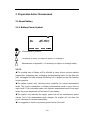
2.1.1 Battery Power Symbol
Vz:
HR:
Save
92°18’22”
187°07’15”
Set0
SetA
P1/2
Measurement is possible
The battery is lower, it is better to replace or recharge it
Measurement is impossible, it is necessary to replace or recharge battery
NOTE:
◆The working time of battery will be effected by many factors, such as ambient
temperature, recharging time, recharging and discharging times. On the data safe
side, we suggest the users recharge the battery full or prepare several full batteries
before operation.
◆The battery symbol only indicates power capability for current measurement
mode. The power consumption in distance measurement mode is more than in
angle mode, if the instrument enters into distance measurement mode from angle
mode, the power maybe auto-off because of lower battery.
◆The symbol only indicates the supply power but not the instantaneous power
change. And if the measurement mode changes, the symbol will not show the
power’s decrease or increase immediately.
◆It is suggested to check every battery power before field work.
8/62
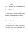
2.1.2 Replace the Battery
1.Remove the battery
①Press the button downward as shown
left
② Remove the battery by pulling it
toward you
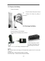
2.1.3 Recharge the Battery
2.Mount the battery
①Insert the battery to the instrument
②Press the top of the battery until you hear a
Click.
As above figures show, connect
the charger and the battery, then
plug the charger into the outlet
of 110V-220V AC power supply, recharging will begin.
NOTE:
◆The indicator light on the charger will illuminate three separate colors for varies mode
conditions:
Solid Red Light—indicates that the charger is working;
Solid Green Light— indicates that the charge has finished;
9/62
Flashing Red Light—indicates no battery on charging, poor connection or some
problems exist.
◆It is recommended to continue charging for 1 or 2 hours after the light turn green.
◆Once the red light flashes constantly after the charger is plugged into the outlet of
110V-220V AC power supply, please remove the battery and reconnected it after 3 or 5
min.
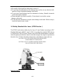
2.2 Setting Up the Instrument
Mount the battery in the instrument before performing this operation because the
instrument will tilt slightly if the battery is mounted after leveling.
I.Set up the tripod first: extend the extension legs to suitable lengths and tighten
the screws on the midsections. Make sure the legs are spaced at equal intervals and
the head is approximately level. Set the tripod so that the head is positioned over
the surveying point. Make sure the tripod shoes are firmly fixed in the ground.
II.Mount the instrument on the tripod head. Supporting it with one hand, tighten
the centering screw on the bottom of the unit to make sure it is secured to the
tripod.
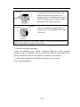
2.3 Centering and Levelling-Up
1.Position tripod legs so that the plummet is aimed to the ground mark point. Turn
the focusing ring of the optical plummet to focus.
2.Turn three footscrews of the tribrach till the center of reticle exactly coincides
with the surveying point in any position.
3.Move the tripod legs to centre the circular level. The instrument is now roughly
leveled-up.
4.Center the bubble in the circular level
10/62
Screw B
Screw A
Loosen the horizontal motion clamp, and
turn the instrument till the plate level is
perpendicular to a line shaped with screws A
and B. Adjust the screws A and B to make
the bubble in the center of the level.
Plate level
Screw C
Screw B
Screw A
Turn the instrument approximately 90 °
Adjust screw C, till the bubble in the center
of the level.
Screw C
Repeat above steps until the bubble remains in the center of the plate level
while the instrument is rotated to any position.
5.Center the surveying point again
Loosen the centering screw slightly. Looking through the optical plummet
eyepiece, slide the instrument over the tripod head until the surveying point is
exactly centered in the reticle. Re-tighten the centering screw securely.
6.Check again to make sure the bubble in the plate level is centered.
If not, repeat procedure 4.
11/62
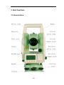
3. Basic Functions
3.1 Nomenclature
12/62
13/62
3.2 Basic Key Operation
Keys
F1 ~ F4
0~9
.
±
Power
★
ENT
ESC
ANG
DIST
CORD
MENU
Description
Select the functions matching the softkeys
1. Input number when numeric input
2. Input characters when alphabetic input
Input a decimal point
Input plus / minus sign
Power On / Off
Enter into setting mode directly
End dialog and save setting to file
Escape to the previous menu or mode;end dialog and not save
1. Enter into angle measurment mode(under basic measurement
mode)
2. Up arrow
1. Enter into dist and angle measurment mode(under basic
measurement mode)
2. Down arrow
1. Enter into coordinate and angle measurment mode(under basic
measurement mode)
2. Left arrow
1. Enter into menu mode(under basic measurement mode)
2. Right arrow
Note: 1. ”Power” indicate
2. Basic measurement is composed of angle and dist and coordinate
measurement mode
3.3 Display
The LCD could display 6 lines with 24 characters per line. In measurement mode,
it displays some common information in above 5 lines and displays soft functions
in the last line.
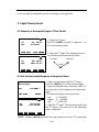
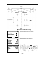
3.4 Mode Diagram
15/62
Vz:
HR:
92°18’22”
187°07’15”
angle mode/basic measurement mode
Save
Set0
[DIST]
SetA
P1/2
--Collection--
[ANG]
1.Select file
▲
2.Setup station
3.Setup BSS
4.Sequence of collection
5.Collection
▼
Dist mode/basic measurement mode
Vz:
92°18’22”
HR:
187°07’15”
SD:
m
HD:
VD:
Save Meas Mode P1/2
[1]
1.Setup station
2.Setup BSS
3.Setout
4.Odd coordinate
5.Intersection
6.Input coordinate
[2]
[CORD] [DIST]
Coordinate mode/basic measurement mode
Vz:
92°18’22”
HR:
187°07’15”
N:
m
E:
Z:
Save Meas Mode P1/3
[3]
[4]
--Menu--
▲
[ESC]
[5]
▼
▲
▼
--Fileman--
1.Fileman
2.Import
3.Export
4.Disk format
5.Disk information
6.Input coordinate
▲
▼
--Program--
1.REM(Height meas)
2.MLM
3.Coor.Z
4.Area
5.Point projecting
6.Roadway
Menu mode
1.Collection
[MENU]
2.Setout
3.Fileman
4.Program
5.parameter
6.Calibration
--Setout--
▲
▼
--Parameter--
1.Units(angle)
▲
2.Units(dist)
---------------------------3.HA mode
4.VA mode
5.EDM mode
▼
--Calibration--
1.Index error
▲
2.Tilt error
---------------------------3.Add Const
4.Mul Const
▼
16/62
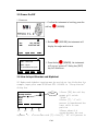
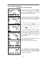
3.5 Power On/Off
I.Power on
1.Confirm the instrument is leveling, press the
red key
Vz:
HR:
Save
92°18’22”
187°07’15”
Set0
SetA
[POWER].
2.Release
[POWER],the instrument will
display the angle mode screen.
P1/2
II. Power off
ENT->Shut92°18’22”
off
Vz:
HR:
187°07’15”
ESC->Quit
3 seconds auto quit
Save
Set0
SetA
3.Press the key
[POWER], the instrument
will pop up “power off” dialog box,[ENT]
key will shut down.
P1/2
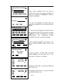
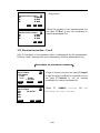
3.6 How to Input Number and Alphabet
All Number and alphabet inputing must be carried out in a dialog box.for
example,input point name SUN1A and STN -123.456 in “Setup station”
dialog box
1.Press [F3],the soft key
prompt will switch
“Alph.”.
2.Press [7],’S’will
present in inputbox and the
caret shift to next
position
3.Pause about 0.4
[F1]
[F2]
[F3]
[F4]
second,because the next
alphabet ‘U’is relational with [7].click [7],’SS’will present in
Setup station
Pt.name
STN
STE
STZ
B.S. Clear Alph. Enter
[F1]
[F2]
[F3]
[F4]
Caret
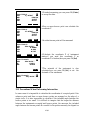
17/62
inputbox,click [7] again ‘ST’will
present in inputbox,click
[7]again,’SU’will present in input box.
4.Click [5], ’SUN’will present in input
box.
5.Press [F3],switch into Number input mode
6.Press [1],’SUN1’ will present in input box
7. Press [F3],switch into Alphabet input mode
8.press [1],’SUN1A’ will present in input box
9.press [F4],the cerat will shift into STN input box,because the STN coordinate is
Number attribute,the prompt “Alph.” automatically switch into “Num.”,
10. input [±],[1],[2],[3],[.],[4],[5],[6] in turn,
11.press [ENT],end dialog
Setup station
Pt.name SUN
STN
STE
STZ
B.S. Clear Num. Enter
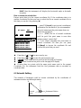
3.7 How to Configure
Press key {★} directly to enter into in any status, and do some basic settings.
Reflector:
Prism
Contrast:
5
◆
[*] Choose file
Light Tilt LASER Factor
Reflector:
1.Backlight
Press [F1], the backlight will be switched on or
off
2.Tilt
Press [F2],the tilt sensor status will be present
Press [F2] again the tilt sensor will be switch on
or off
Prism
[ESC] will quit tilt sensor status display
Contrast:
◆
3.Laser
Tilt:X=-50 5
Press [F3],the “laser func.”dialogbox will
[*] Choose file
appear,press [F3]again the laser beam will emit
Light Tilt LASER Factor
from object lens or sewitch off by
turns.[F1]&[F2] can adjust the brightness of the
Laser func.
plummet laser.
F1 Plumb +
4.Reflecting object
F2 Plumb –
Press the EDM mode will be switched
F3 Point to(switch)
between “prism”,”no prism” and “reflector
F4 Quit
board”
5.LCD contrast
Press ▼▲,will increase or decrease the value of contrast
6.factor
18/62
Temperature:
25
℃
Press:
1013.0 hPa
Prism const:
0 mm
PPM:
4ppm
Signal:
B.S. Clear Sigal Enter
Press [F4], pop up “atmosphere parameter
setting” dialog box,after you input
temperature and atmospheric pressure,the
PPM value will be calculated
automatically.when you press [F3] the EDM
will return current EDM signal.[ESC] will
quit signal show;
Another setting and config is operated by main menu—“parameter”
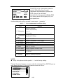
able 3-1 List of measurement condition setting
Options
Item
1. Unitsoption
DMS*/GON/MIL;
Meter*/feet/feetinch;
℃*/℉
hPa*/mmHg
2. Unitsoption
InterFeet*/US Feet
(dist)
3.K option
0﹡/0.14 / 0.20
4.VA display
Zenith﹡/ Horizon 0 / V90 / slope
5.HA display
6.Auto shut off
7.Coord
HAR﹡/ HAL
Never*/5min/10min/20min
N-E-Z﹡/ E-N-Z
8. EDM mode
9.mini readout
Single*/repeat/Continue/Track
0.Language
English*/spaish/portuguese
1”*/5”/10”
NOTE:
◆ Every first options with the symbol “﹡”are the factory setting.
Through the menu function ,you can config the instrument.Press [MENU],pop up
main menu then select [5],the config menu is shown as follow:
--Parameter-1.Units(angle)
▲
2.Units(dist)
---------------------------3.HA mode
4.VA mode
5.EDM mode
▼
19/62
You can config all instrument options according to your appliction
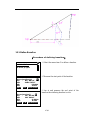
4. Angle Measurement
4.1 Measure a Horizontal Angle of Two Points
Vz:
HR:
Save
92°18’22”
0°00’00”
Set0
SetA
P1/2
1.Sight the 1st target.
Press F2: [SET0] to set the 1st target as 0°at
P1 in the measure mode.
2.Sight the 2nd target. The displayed value is
the included angle between two points.
1st target
Vz:
HR:
Save
2nd target
92°18’22”
187°07’15”
Set0
SetA
P1/2
4.2 Set the Horizontal Angle to a Required Value
Set H.angle
HR:
123.0005
B.S. Clear
Vz:
HR:
Hold L/R
Enter
92°18’22”
123°00’05”
Vmode
1.Take your instrument sight the 1st target.
Press F3: [SETA] at P1 in the measure mode.
2.Input the required value, then press {ENT} to
save the value. And it displays as the horizontal
angle.
The range and format of the input value:
gon:
0 ~ 399.9999
degree: 0 ~ 359.5959
mil:
0 ~ 6399.999
3.Sight the 2nd target. The horizontal angle from
the 2nd target to the value set as the horizontal
angle is displayed.
P2/2
NOTE: Pressing [HOLD] performs the same function as above. The horizontal
20/62
angle is in hold status when “HOLD” is present. Press [HOLD] again to releasse
the holding status.
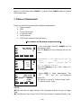
5. Distance Measurement
Please set the following items before distance measurement:
●
Prism constant
●
PPM
●
Grid scale(if need)
●
K option(if need)
●
Select reflector
●
EDM mode setting by the application
【Procedure of distance measurement】
Vz:
92°18’22”
HR:
187°07’15”
SD:
m
HD:
VD:
Save Meas Mode P1/2
>Sigl
92°18’22”
Rept
187°07’15”
Cont
m
Vz:
HR:
SD:
HD:
Track
VD:
Save Meas Mode P1/2
Vz:
85°21’22”
HR:
187°07’15”
SD: #Cont
4.804m
HD:
4.789
VD:
0.389
Save Meas Mode P1/2
1.Aim at the target. Press F2: [MEAS] at P1 in
the measure mode.
Press F1:[Save]will start measuring and save the
result
2.According to the application,you can
select
one
of
“single””repeat””continue”and”tr
ack”to measure distance
Press [F3]:[Mode],pop up a little window for
your selection
3.Press [ESC] to finish measurement. The
“ SD ” , ” HD ”, and ” VD ” will display as
shown left.
“# “indicate “no prism”or “reflector board” mode
“*” indicate “prism” mode
NOTE:
◆Make sure that the target setting in the instrument matches the type of target
used.
◆If the objective lens is dirty, it will affect the accurate of measured results. Dust
21/62
it off with your special brush and wipe it with your special cloth (in your
carrring case) before putting away.
◆If an object with a high reflective factor (metal, white surface) exists between
the instrument and the target when measuring, the accuracy of the measured
results will be affected.
◆An angle is also able to be measured when distance measurement.
◆ # or * means measuring distance,at end of ”single”,”repeat” mode
measuring ,the symbol will disappear automatically. you can press [ESC] finish
measurement then the symbol also disappear.
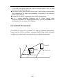
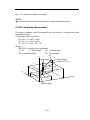
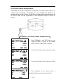
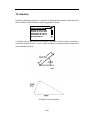
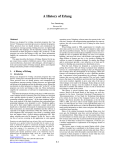
6. Coordinate Measurement
It is possible to find the 3D coordinates of a target by coordinate measurement.
Please input the Station coordinate, instrument height, target height, backsight
coordinate (or azimuth angle) and azimuth before coordinate measurement.
○
N
Z
Target Ht
Inst. Ht
Target point
Occiped point
E
22/62
6.1 Input the Occupied Point Data
【Procedure of inputting occupied point data】
1.Measure the height of target and instrument
with a tape, etc.
92°18’22”
Vz:
HR:
0°00’18”
N: cont
m
E:
Z:
Save Meas Mode P1/3
2.Press F4: [P1/3] at P1 in the measurement
mode to next page
3.Press F3:[STA] to setup station.
Vz:
92°18’22”
HR:
0°00’18”
N: cont
m
E:
Z:
Height BSS STA P2/3
Set station
>STA:
Code
I.H.:
1.800
* file list
Input Search Info
Read
Set bss
>BSS:
Code
T.H.:
1.800
* file list
Input Search Info
Set Save
bss record?
>BSS:
ENT—save
Code
T.H.:
1.800
ESC—Not
save
* file list
Input Search Info
Set Aim
bss at BS?
>BSS:
ENT—set HA
Code
T.H.:
1.800
ESC—Quit
* file list
Input Search Info
Read
Read
4.Press F1:[Input] the station coordinate,note
to input a point name.if the station is a known
point whose information have been saved in
current coordinate file,then you can press
F2:[Search] to call a point (coordinates)
information for the station.if you cannot
remember the point name in current coordinates
file then you can press F4:[Read] to browse the
coordinate file and find out the point that you
need.Press F3:[Info] you can see all the
information of the station if you have got the
point.
5.Press [ENT] to receipt the station data.
6. in like manner you can get a BSS coordinate
7.Press [ENT] ,the instrument will prompt if
you need to save the record or not.
8.and then prompt if you need to setup a
azimuth using the BSS data or not.if you select
Read
23/62
[ENT] then the instrument will display the horizontal angle as Azimuth
evermore.
How to obtain the existed data:
Known point data is in the current coordinate file. If the coordinates data is in
another coordinate file then you have to select the file as current coordinate file.in
this time you can do it by pressing[★]
ST name
B.S.
Alph.
A01
Clear
Pt.(B.COO) 1/15
A001:100.0 100.0
A002:100.0 100.0
A003:100.0 100.0
A004:100.0 100.0
A005:100.0 100.0
Begin End Read Pick
1. press F2:[Search] to get a point (coordinates)
information for the station.if you can remember
the point name,input the point name shown as
the picture on the left:
2.press [ENT]The list of existed coordinate
swill be got;if the point name is error then
system prompt “cannot find”
3. if you cannot remember the point name in
current coordinate file then you can press
F4:[Read] to browse the coordinate file and
find out the point that you need
◆ Press keys { } / { } to move one by one.
◆ Press keys { } / { } to turn the previous/next page.
◆ [Begin]: Press it and the first point on the first page will display.
◆ [End]: Press it and the last point on the last page will display.
◆ If more than two points with the same point name exist in the current
Coordinate file, the instrument finds the first pointname data as recorded by
coordinate date.
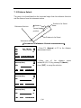
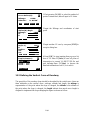
6.2 Azimuth Setting
The azimuth of backsight could be inverse calculated by the coordinates of
instrument station and backsight station.
N
0
Azimuth
Instrument Station
Angle
E
24/62
see “§6.1 Input the occupied point data”.
NOTE:
◆You can input the azimuth angle directly in angle measurement mode.
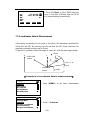
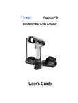
6.3 3D Coordinate Measurement
The target coordinate could be measured after the setting of occupied point and
backsight azimuth.
The formular used to calculate:
N1=N0+S×sinZ×cosAz
E1=E0+S×sinZ×sinAz
Z1=Z0+S×cosZ+IH-TH
Where:
N0-E0-Z0: occupied point coordinates
S:SD
Z:Zenith angle
Az:Azimuth angle
IH:Instrument height
TH:Target height
SD
Z
Zenith angle
IH
Target height
Target (N-E-Z)
HD
N0-E0-Z0
N
E
Azimuth angle
25/62
【Procedure of 3D coordinates measurement】
1.Aim at the target point.
2.Select F2:[Meas] to start. The coordinate
Vz:
92°18’22”
value of the target is displayed.
HR:
0°00’18”
N: cont
m
3.Press F2: [STA] @ P2/3 to re-input the
E:
occupied data if necessary, see Ҥ6.1 Input the
Z:
Save Meas Mode P1/3
occupied point data”.
Input I.H. &T.H.
I.H.:
4.Press F1:[Height] @ P2/3 to re-input the
target height and instrument height if necessary,
T.H.:
m
and press F1: [MEAS] to continue. Follow this
operation
till
all
targets
have
B.S. Clear Save Enter
been measured.
5.Press key [ESC] to stop EDM measuring,
when EDM mode is“Continue”,”Repeat”or “Track”
7. Stake out Measurement
Setout measurement is used to Setout the required point. The difference between
the previously inputted data to the instrument(the Setout data)and the measured
value can be displayed by measuring the horizontal angle, distance or coordinates
of the sighted point.
The horizontal angle difference and distance difference are calculated and diplayed
using the following formulars:
Horizontal angle difference
dHA=Horizontal angle of Setout data – measured horizontal angle
Distance difference
Distance
Displayed item
SD: S-O SD=measured slope distance – slope distance of Setout data
HD: S-O HD=measured horizontal distance – horizontal distance of Setout
data
VD: S-O VD=measured height difference – height difference of Setout data
NOTE:
◆Setout data can be input in various modes: SD, HD, VD, coordinates and REM
measurement.
◆EDM settings could be set in this mode.
26/62
7. 1 Distance Setout
The point to be found based on the horizontal angle from the reference direction
and the distance from the instrument station.
Position to be Setout
distance
Reference direction
Present target
position
Distance to be Setout
Instrument station
【Procedure of distance Setout measurement】
Vz:
92°18’22”
HR:
187°07’15”
SD:
m
HD:
VD:
Offset Setout m/f/iP2/2
Setout(dist)
HD:
B.S.
m
Clear
1.Press F2: [Setout] at P2 in the distance
measurement mode.
2.Select one of the distance setout
modes(HD,SD,VD) by pressing F3:[Mode]
Press [ENT] to accept the selection
Mode Enter
Setout(dist)
SD:
B.S.
m
Clear
Mode Enter
Setout(dist)
VD:
B.S.
m
Clear
Mode Enter
27/62
Vz:
HR:
SD:
dhd:
VD:
Save
92°18’22”
187°07’15”
Meas
m
3.Press F2:[Meas] to Start EDM,when the
error is less than 0.002mm then the EDM
will stop measuring automatically.
Mode P1/2
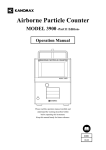
7.2 Coordinates Setout Measurement
After setting coordinates for the point to be Setout, the instrument calculates the
Setout HA and HD. By selecting the HA and then the HD Setout functions, the
required coordinate location can be Setout.
To get the Z coordinate, attach the target to a pole etc, with the same target height.
N
Distanc
0
Back sight
station
ee
Point to be
Setout
Instrument
station
Angle
E
【Procedure of coordinate Setout measurement】
--Menu--
1.Collection
2.Setout
mode.
3.Fileman
4.Program
5.parameter
6.Calibration
▲
1.Press [MENU] in the basic measurement
▼
--Setout--
1.Setup station
2.Setup BSS
3.Setout
4.Polar coordinate
5.Intersection
6.Input coordinate
▲
2.Select “ 3.Setout”.
▼
28/62
Input point for setout
N:
E:
m
Z:
B.S. Clear Search
Enter
3.Input point coordinate that you need to
setout.if the point is in current coordinate file
then you can press F3:[Search] to obtain a
known coordinates.
Pt.name
B.S.
Alph.
4.If you can remember the point then you
input the pointname,else you can press directly
[ENT].
Clear
Pt.(B.coo)1/19
1A: 100.000 120.000
A001: 100.000 100.000
A002:290.000 290.000
A003:101.000 180.000
A004:202.000 270.000
Begin End Read Pick
Input point for setout
N:
100.000
E:
100.000 m
Z:
0.000
B.S.
Enter
Clear
Search
5.The point list will appear.you search the point
that you need in the list,if you find the you press
F4:[Pick] to get the coordinate.else you press
[ESC],system
will
recommend
another
coordinate file for you to get the coordinate.
6.The coordinate information will appear in the
dialog box.Press [ENT] system accept your
input.
Calculate-Setout
HR:
HD:
Dist
HR:
dHR:
HD:
dHD:
dZ:
Meas
HR:
dHR:
dN:
dE:
dZ:
Meas
50°11’39”
156.205
7.System calculate Azimuth DR horizontal
distance HD,then you can select one of two
setout mode—distance or coordinate
Coor.
0°00’18”
-50°11’22”
m
Mode
T.H.
Next
0°00’18”
-50°11’22”
m
Mode
T.H.
Next
8.Distance setout mode, we expect that dHR and
dHD tend to zero.
9.Coordinate setout mode, we expect that dHR
and dN,dE,dZ tend to zero.
29/62
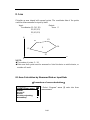
8. Area
Calculate an area shaped with several points. The coordinate data of the points
could be either measured or input by hand.
Input:
Output:
Coordinates: P1 (N1, E1)
Area:S
P2 (N2, E2)
P3 (N3, E3)
…
N
P3
P2
P4
S
P1
P5
E
0
NOTE:
◆The number of points: 3 ~ 20.
◆Make sure these points must be measured or listed clockwise or anticlockwise, or
mistake will result.
8.1 Area Calculation by Measured Data or Input Data
【Procedure of area calculation】
--Program--
1.REM(Height meas)
2.MLM
3.Coor.Z
4.Area
5.Point projecting
6.Roadway
▲
1.Select “Program” menu [4] enter into Area
measurement
▼
30/62
Survey(Area)
Pt01: 100.000 120.000
Input Meas DEL
CALC
Point(Area)
N:
E:
Z:
B.S. Clear Search
m
3.Input a point coordinate or you can press
F3:[Search] to call an existing coordinate.
Enter
Survey(Area)
Pt01: 100.000 120.000
Pt02: 100.000 100.000
Input Meas DEL
2.Area measurement interface is shown as the
picture on the left.you can press F1:[Input] a point
or call an existing point
4.After inputing the coordinate.the coordinate
always is inserted behind the last select bar,and
current coordinate turn into a selected bar.
CALC
Survey(Area)
Vz:
92°18’22”
HR:
187°07’15”
N:
200.000m
E:
290.000
Meas
mode Enter
5.You can press F2:[Meas] to abtain a unknown
point coordinate.this time you have to start
EDM.after distance measurement the unknown
point coordinate is shown as the picture on the left.
6.Press F4:[Eneter] to accept the measured point
coordinate.
Survey(Area)
Pt01: 100.000 120.000
Pt02: 100.000 100.000
Pt03: 200.000 290.000
Input Meas DEL
CALC
Survey(Area)
Area=1000.0sq.m.
Pt01: 100.000 120.000
=:0.1ha.
Pt02:
100.000 100.000
Pt03:
200.000 290.000
=:0.2471acre
Perimeter=431.94m
Input Meas DEL
7.After the numbers of points is more than 2,the
calculation is possible.then you can press
F4:[CALC]the Area and Perimeter of the shape
that is surrounded by the points in list box;
CALC
31/62
Graphics
8.To obtain a result these points must be
measured
or
listed
clockwise
or
anticlockwise.this time you can press[ ★ ]to
check it.the shape is shown as the picture on the
left.
9. Offset Measurement
Offset measurement are performed in order to find a point where a target cannot be
installed directly or to find the distance and angle to a point which cannot be
sighted.
It is possible to find the distance and angle to a point you wish to measure (target
point) by installing the target at a location (offset point) a little distance from the
target point and measuring the distance and angle from the surveying point to the
offset point.
The target point could be found in the following four ways.
9.1 Distance Offset Measurement
Sometimes we need to measure a coordinate of a point such as A1 whose position
cannot place a prism .assum that we know the horizontal distance from prism to
A1. the Distance offset measurement can be used.
32/62
【Procedure of distance offset measurement】
Offset(dist)-Length
1.Input the known offset distance
Left(-)/Right(+)length
Front(-)/Behind(+)Len
B.S.
Clear
Enter
Offset(dist)-Prism
HR:
SD:
HD:
VD:
Meas
356°50’27”
T.H.
2.Aim at the prism to start EDM, if you need the
coordinate of A0 you should set the height of
prism to zero.if you need the coordinate of A1
you should set the height of prism to the real
height.
Mode
Offset(dist)-Prism
HR:
SD:
HD:
VD:
356°50’27”
4.387
4.373
0.855
Meas
Mode
Enter
Offset(dist)-Target
HR:
SD:
HD:
VD:
Next
31°40’09”
14.902
9.193
0.855
Mode
3.The result is shown as the picture on the
left.Press F4:[Enter] to accept the result.
4.The result of target point is shown as the
picture on the left.if you wish to display
coordinate then you must press [CORD],or if
you wish display distance then you must press
[DIST].
5.When you press F1:[Next] ,you will be
informed to save the result, if nessary you can
press [ENT] to save the result.
33/62
9.2 Angle Offset Measurement
Sometimes we need to measure a coordinate of a point such as A1 whose position
cannot place a prism. Assume that we know that the horizontal distance from CI to
A1 and the distance from CI to prism are equal. The angle offset measurement can
be used.the figure is shown as follow.
Note: if you need the coordinate of A0 you should set the height of prism to zero.if you need the
coordinate of A1 you should set the height of prism to the real height.
34/62
【Procedure of angle offset measurement】
--Offset--
1.Angle offset
2.Dist offset
3.Plane offset
4.Column offset
▲
Offset(angle)-Prism
HR:
SD:
HD:
VD:
Meas
356°50’27”
T.H.
Mode
Offset(angle)-Prism
HR:
SD:
HD:
VD:
356°50’27”
4.582
4.567
0.371
Meas
Mode
Next
.
2.Start EDM , if you need the coordinate
of A0 you should set the height of prism
to zero.if you need the coordinate of A1
you should set the height of prism to the
real height.
3.The result of the point positioned prism is
shown as the picture on the left. Press
F4:[Enter]
Enter
Offset(angle)-Target
HR:
N:
E:
Z:
1.Select the function of angle offset
measurement
1°53’10”
4.565
1.150
0.871
4.The result of the target point appear.
If you wish to display coordinate then you must
press [CORD],or if you wish display distance
then you must press [DIST].
Mode
.5.When you press F1:[Next] ,you will be informed to save the result, if nessary
you can press [ENT] to save the result.
9.3 Plane Offset Measurement
Sometimes we wish to obtain the coordinate of some points where we
cannot measure directly distance. Fortunately, we can measure the distances
of another points, and all these points are in a plane. At this time the plane
offset measurement can be used. The figure is shown as follow:
35/62
【Procedure of Plane offset measurement】
Offset(Plane)-pt.1
HR:
SD:
HD:
VD:
1°55’42”
4.847
4.831
0.393
Meas
Mode Enter
Offset(Plane)-pt.2
HR:
SD:
HD:
VD:
Meas
T.H.
HR:
SD:
HD:
VD:
Mode Enter
9°36’37”
5.223
5.165
0.776
T.H.
Next
3.In like manner as step 1,obtain the datas of P3
Mode Enter
Offset(Plane)-Target
HR:
N:
E:
Z:
2.In like manner as step 1,obtain the datas of P2
9°36’37”
5.182
5.165
0.420
Offset(Plane)-pt.3
Meas
1.Press F1:[Meas],start EDM to obtain the
Azimuth and distance of P1.Press F4:[Enter] to
accept the datas
5°10’04”
4.936
0.446
2.245
4.When you aim at the point located in the
plane,the coordinates is calculated.
Mode
36/62
9.4 Column Offset Measurement
Sometimes we wish to obtain the coordinate of column center where we
cannot find out directly. Fortunately, we can measure the distances of
another points on the column. At this time the plane offset measurement can
be used to find out the coordinates of the center.the figure is shown as
follow:
【Procedure of Column offset measurement】
Offset(Col)-Prism
HR:
SD:
HD:
VD:
1°55’42”
4.836
4.832
0.193
Meas
Mode Enter
Offset(Col)-left edge
HR:
SD:
HD:
VD:
1. Press F1:[Meas] to start EDM then you can
obtain the data of a point on the column
which is shown as the picture on the left.
2. Aim at the left edge of the column, get its data
0°14’19”
4.836
4.832
0.193
Mode Enter
Offset(Col)-Right edge
HR:
SD:
HD:
VD:
3°35’23”
4.836
4.832
0.193
3. Aim at the left edge of the column, get its data
Mode Enter
Offset(Col)-Center
HR:
N:
E:
Z:
Next
1°54’49”
4.975
0.166
0.693
Mode
4. The coordinates of the column center is
calculated and shown as the picture as the left.
37/62
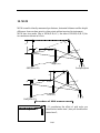
10. MLM
MLM is used to directly measure slope distance, horizontal distance and the height
difference from one base point to other points without moving the instrument.
MLM have two mode, One is MLM(A-B,A-C), the other is MLM(A-B,B-C),the
two modes are shown as follow.
H2
S2
V2
%2
H1
V1
S1
%1
Target (P3)
Target (P2)
Start point (P1)
Occupied point
H2
%2
V2
S2
H1
V1
S1
%1
Point (P3)
Point (P2)
Start point (P1)
【Procedure of MLM measurement】
Grid coefficient
1.with grid scale
2.without grid scale
▲
1.If considering the effect of grid scale you
should select menu item 1,else you should select
menu item 2;
38/62
2.Select one of two modes
--MLM--
1.MLM(A-B,A-C)
2.MLM(A-B,B-C)
▲
MLM(A-B,A-C)-Step 1
Vz:
88°18’22”
HR:
1°46’31”
HD:
m
Meas
T.H.
coor. Mode
MLM(A-B,A-C)-Step 1
Vz:
88°18’22”
HR:
1°46’31”
HD:
4.827m
Meas
T.H.
T.H.
4.The data of the base point is shown as the
picture on the left.
coor. Mode
MLM(A-B,A-C)-Step 2
Vz:
84°52’25”
HR:
14°27’05”
HD:
5.458m
Meas
3.Press F1:[Meas] to start EDM then you can
obtain the coordinates of the base point,or Press
F3:[Coor.] then you can call an existing
coordinate from current coordinate file.
5. Press F1:[Meas] to start EDM then you can
obtain next coordinates,or Press F3:[Coor.] then
you can call an existing coordinate from current
coordinate file.
coor. Mode
MLM(A-B,A-C)-Result
dSD:
1.343
dHD:
1.297
dVD:
0.347
HR:
69°11’30”
6.There are dSD (slope distance),dHD(horizontal
distance),dVD(difference of height) and azimuth
attributes between two points.these attributes are
shown as the picture on the left.
Next
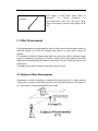
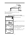
11. Height measurement (REM)
REM is a function used to measure the coordinate and height to a point where a
target (prism) cannot be directly installed such as power lines, overhead cables or
bridges, etc.
39/62
Target point B
α2
H2
S
Ht
α1
H1
B’
Here is the
equation used to calculate the data presented in above figure:
Ht=H1+ S*cosα1*tgα2-S*sinα1
H2= S*cosα1*tgα2-S*sinα1
【Procedure of REM(Ht—Ground to target)】
1.Select menu item 1 when you need the
Survey(Height)
height
1.Ground to target
▲
2.Point to point
between the target and ground.
2.Setting height of instrument and the height
of prism
Input I.H. &T.H.
I.H.:
1.500
T.H.:
B.S.
1.000
Clear
Save
m
Enter
Height-Prism
Vz:
88°18’22”
HR:
1°46’31”
HD:
4.827m
Meas
Mode Enter
Height-Gnd to target
Vz:
88°18’22”
HR:
1°46’31”
VD:
1.000m
T.H.
3.Press F1:[Meas] to start EDM then you
can obtain the horizontal distance between
the instrument and the target.Press F4:[Enter]
to accept the measurement data
4.Then
VD(difference
of
height)
appear,first display the height of prism.
HDist
40/62
Height-Gnd to target
Vz:
88°06’28”
HR:
1°46’31”
VD:
1.017m
T.H.
HDist
5. If you rotate the telescope then VD will
change, when you aim at the target the VD is
the difference of height between the target and
ground.
【Procedure of REM(H2—point to point)】
Survey(Height)
1.Ground to target
2.Point to point
▲
Height-Prism
Vz:
88°18’22”
HR:
1°46’31”
HD:
4.827m
Meas
1.Select menu item 2 when you need the
difference of height between any two points
2. Press F1:[Meas] to start EDM then you can
obtain the horizontal distance between the
instrument and the target.Press F4:[Enter] to
accept the measurement data
Mode Enter
3. At this time, the point where posite prism is
base point.
Height-Base
Vz:
88°18’22”
HR:
1°46’31”
VD:
0.000m
Enter
Height-target
Vz:
80°56’52”
HR:
1°46’31”
VD:
0.626m
4.The VD will change when you rotate telescope.
If you need setting another base point then you can
aim at another base point and press F2:[Next A].
Next A. HDist
41/62
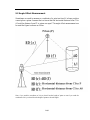
12. Intersection
Intersection program is used to determine the coordinates of an instrument station
(unknown) by measuring several known points. Coordinate data in memory could
be read.
Input
Coordinates of known points: Xi, Yi, Zi
Measured HA: Hi
Measured VA: Vi
Measured distance: Di
Output
Coordinate of occupied data: Xo, Yo, Zo
Known point P1
Known point P2
Occupied point P0
Known point P4
Known point P3
NOTE:
◆All N, E, Z value or only Z value of the occupied point is calculated by
measuring known points.
◆ Coordinate intersection measurement overwrite the N, E, Z data of the
instrument stattion,
◆Inputted known coordinate data and calculated data could be recorded in the
current coodinate file.
◆Max number of known points is 5
42/62
12.2 Coordinates Intersection
【Procedure of Intersection】
Intersection-P1
>Pt.name:
Code
T.H.:
1.000
* file list
Input Search Info
1.Input a known point.you can press F1:[Input]
to input the point coordinate by coordinate,or
you can press F2:[Search] to call an existing
coordinates for current coordinates file.
Read
Intersection-Pt.1
Vz:
80°00’13”
HR:
340°56’50”
SD:
T.H.:
1.000m
Angle Dist
Intersection-Pt.1
Vz:
80°00’13”
HR:
340°56’50”
SD:
4.890
T.H.:
1.000m
Next
Intersection-Pt.2
Vz:
83°07’52”
HR:
3°40’00”
SD:
6.409
T.H.:
1.000m
Next
Calc
Intersection-result
dN:
0.000
dE:
0.001
dZ:
0.000
MdHD:
0.004
Set ST SetA Rec dCoor
Intersection-result
N:
-0.004
E:
0.003
Z:
0.003
Set ST
SetA
Rec
Coor
2.Aim at the point that you have inputed its
coordinates.then you can select one of angle and
distance mode to do Intersection measurement.
3.If you have selected the distance mode
then you need to press F1: [MEAS] starting
EDM
and
obtaining
the
slope
distance.after measuring distance,you
press F1:[Next] to measure next point.
4.If you have measured two or more distance
the prompr “Calc” will appear.in another way,if
you have measured three or more then the
prompr “Calc” will appear.in this time you can
press F4:[Calc]to obtain the coordinates of
instrument station.
5.The result of calculated instrument station is
shown as the picture on the left.
This is the error of the station coordinates
6.Press F4:[dCoor] the coordinate of intrument
station will be shown.you can Press F1:[Set ST]
to setup station and press F2:[Set A] to setup the
Azimuth of the instrument.
43/62
Intersection-result
N:
-0.004
E:
0.003
Z:
0.003
SetA
Rec
Coor
Intersection-result
N:
-0.004
E:
0.003
Z:
0.003
Rec
7.Setup station.
8.Setup the azimuth of the instrument.and you
can press F3:[Rec] to save the coordinates to
current measurement file.
Coor
12.2 Elevation Intersection—Coor.Z
Only Z (elevation) of an instrument station is dertermined by this measurement.
Between 1 and 5 known points can be measured by distance measurement only.
【Procedure of elevation resection】
Coor.Z-No.1
>Pt.name:
Code
T.H.:
1.000
* file list
Input
Search
Read
Info
Coor.Z-No.1
HR:
1°46’36”
SD:
HD:
VD:
Meas
1.Input a known point.you can press F1:[Input]
to input the point coordinate by coordinate,or you
can press F2:[Search] to call an existing
coordinates for current coordinates file
2.Press F1: [MEAS] starting
obtaining the slope distance.
Mode Enter
44/62
EDM
and
Coor.Z-No.1
HR:
1°46’36”
SD:
4.897m
HD:
4.837
VD:
0.767
Meas
Mode Enter
Coor.Z-No.1
HR:
1°46’36”
SD:
4.897m
HD:
4.837
VD:
0.767
Meas
3.Finished measuring,you can press F4:[Enter]
to accept the data.
Mode
Calc
4.One or more known point can calculate the
coordinate Z
5.Another known point will be measured
Coor.Z-No.2
HR:
23°42’19”
SD:
6.408m
HD:
6.362
VD:
0.767
Next
Mode
Calc
Coor.Z-result
HR:
24°30’41”
Z:
0.002
dZ:
0.000
Set Z
6.Calculate the coordinate Z of instrument
station,if you need this coordinate Z as
coordinate Z of station,then you press F4:[Set]
7.The azimuth of the instrument is also
calculated.you can press F4:[Set] to set the
Azimuth of the instrument.
Coor.Z-result
BSA:
24°30’41”
Set A
12.3 Precautions When Performing Intersection
In some cases it is impossible to calculate the coordinates of occupied point if the
unknown point and three or more known points are arranged on the edge of a
single circle. It is also impossible to calculate if the included angle between the
known points is too small. It is difficult to imagine that the longer the distance
between the instruments occupied and known points, the narrower the included
angle between the known points. Be careful for the points can easily be aligned on
45/62
the edge of a single circle.
An arrangement such as shown below is desirable.
△▲:unknown point
○●:known point
It is sometimes impossible to perform a correct calculation such as shown below.
When they are on the edge of a single circle, take one of the following methods:
(1) Move the instruction station as close as
possible to the center of the triangle.
(2)Measure one more known point which
is not on the circle.
(3)Perform a distance measurement on at
least one of the three points.
13. Point Projection
Point projection is used for projecting a point to an established baseline. By
measuring a point,its offset to start point,the horizontal distance and vertical
distance between the point and baseline can be calculated.the figure is shown as
follow.
46/62
13.1 Define Baseline
【Procedure of defining baseline】
1.Select the menu item 2 to define a baseline
Survey(Height)
1.I.H. &T.H.
2.Set baseline
2.Point project
▲
2.Measure the start point of the baseline
Pt.project(Begin)
Vz:
80°00’13”
HR:
340°56’50”
SD:
4.890m
HD:
4.831
Meas T.H. Mode Enter
Pt.project(end)
Vz:
83°09’38”
HR:
24°30’08”
SD:
6.408m
HD:
6.362
Meas T.H. Mode Enter
3.Aim at and measure the end point of the
baseline.then defining baseline is over.
47/62
【Procedure of point projection】
Survey(Pt.project)
HR:
15°23’50”
X:
-0.903m
Y:
-0.867
Z:
-0.099
Meas T.H.
Mode
Survey(Pt.project)
HR:
15°23’50”
SD:
0.867m
HD:
0.867
VD:
0.009
Meas T.H.
Mode
14. Inverse
The distance and azimuth from a start point to an end point could be calculated
according to input their coordinates.
Input:
Output:
Coordiante of start point: N0,E0,Z0
Distance: D
Coordinate of end point : N1,E1,Z1
Azimuth: Az
N
End point
Az
D
Start point
This function can be implented in MLM when all coordinates is called from the
coordinates file.
48/62
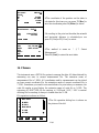
15. Roadway
Roadway application program is composed of designing and roadway setout.when you
select roadway function then the menu is appeared as follow:
--Roadway--
1.Open Raod file
2.New H curve file
3.New V curve file
4.Resume H curve
5.Resume V curve
6.Road Setout
▲
▼
A roadway can be described as a Horizontal curve and a Vertical curve.we describe a
horizontal element by Line、circle、spiral and point of intersection,these shape have
some attribute as follow:
Attribute of cirle and spiral
49/62
Attribute of point of intersection
15.1 Define the Horizontal Curve of Roadway
【Procedure of defining Horizontal Element】
1.Select the mathod of element to define
horizontal roadway.press F1:[Line] first.
Curve define(H)
Mileage:
Azimuth:
Line
Circle
0.000
0°00’00”
Spial
I.P.
Define(H)_Begin
Mileage:
100.0
N:
10
E:
20
B.S. Clear
Enter
3.Input the start azimuth and the length of line
Define(H)_Line
Azimuth:
Length:
B.S. Clear
2.Input the Mileage and coordinates of start
point.
5
50
Enter
50/62
Define(H)_02
Mileage:
Azimuth:
Line
Circle
150.000
5°00’00”
Spial
5.For example,input a circle whose radius is 100
and length is 20;
Define(H)_Circle
Radius:
Length:
100
20
B.S. Clear
Enter
6.Calculate the mileage and azimuth of the
fan-out point
Define(H)_03
Mileage:
Azimuth:
Line
Circle
4.Calculate the mileage and azimuth of the
fan-out point
170.000
16°27’32”
Spial
7.For example,input a spiral whose radius is 240
and length is 45;
Define(H)_Spiral
Radius:
Length:
240
45
B.S. Clear
Enter
8.Calculate the mileage and azimuth of the
fan-out point
Define(H)_04
Mileage:
Azimuth:
Line
Circle
215.000
21°49’50”
Spial
9.Max number of element is 20.press [ENT] to
pop up the list box of all inputed element.Press
F1:[Save] to save all element to current
H-LINE-TYPE file and quit defining.Press
F2:[View] to browse the detailed information of a
element,or to edit it.
List(H element)
01Begin: 100
02Line:
150
03Circle: 170
04Spiral: 215
Save View
Add
【Procedure of defining Horizontal point of intersection】
51/62
Curve define(H)
Mileage:
Azimuth:
Line
Circle
0.000
0°00’00”
Spial
I.P.
define(H)-Begin
Mileage:
1000
N:
10
E:
20
B.S. Clear
Enter
N:(Pt.1)
E:
Radius:
A1:
A2:
B.S. Clear
100
100
50
20
20
Enter
2.Input the Mileage and coordinates of start
point.
3.Input another I.P. one by one.press [ENT] to
accept a dialog box.
4.Press [ESC] to stop inputing,then pop up a list
box of I.P. Press F1:[Save] to save all poins of
intersection to current V-LINE-TYPE file and
quit defining.Press F2:[View] to browse the
detailed information of an I.P.,or to edit it.
List(H element)
01Begin: 100
02I.P.:
150
03I.P.: 170
04I.P.: 215
Save View
1.First pressing F4:[I.P.] to select the mathod of
point of intersection ,then all input is I.P. latter.
Add
15.2 Defining the Vertical Curve of Roadway
The speciality of the roadway slope should be described by the vertial curve, there are
three attributes on the vertical curve—mileage, altitude and length, the mileage is
representative of the point where the slope is changed, the altitude is the altitude of
the point where the slope is changed, the length indicate how much curve length is
disigned to implement the slope changing.the figure is shown as follow.
52/62
The input method of defining vertical curve is just same as the horizontal I.P., see
【Procedure of defining Horizontal point of intersection】
15.3 Roadway setout
When you select road-setout function ,a menu named “road setout” is poped up.
Before setout, you should do something:
1. Load a LINE-TYPE file from file to memory using menu item 1. If you have
defined a roadway just now then you cannot do it;
2. The coordinates of instrument station must be setup, you can use menu item 2
3. The azimuth must be setup, you can use menu item 3.
—Road setout—
1.Select file
2.Setup ST
2.Setup BSS
4.Road Setout
The figure for road setout is shown as follow
53/62
▲
【Procedure of Road setout】
Roadsetout-para
1/2
Start Mile:
100
Space Between
10
B.S. Clear
Enter
Roadsetout-para
Leftdist:
Rightdist:
Left dH:
Right dH:
B.S. Clear
2/2
10
10
0.1
0.1
Enter
Roadsetout-RightEdge
Mile:
100.00
Offset:
10.00
dH:
0.100
T.H.:
1.000
Edit
Setout
1.Input the start mile and space between
2.Input left distance,right distance etc.
3.Use [▲][▼]to set the mile on the stake
that you need to setout ,uset [◄][►] to
select left edge ,center or right edge.if the
mile is not found by [▲][▼],then you can
press F1:[Edit] to input the mile. Then you
can press F3:[Setout]
54/62
Pt.name
Code:
N:
E:
Z:
Rec
100.0
1.000
11.000
0.000
Enter
4.The coordinate of the position on the stake is
calculated,in this time you can press F2:[Rec] to
save the coordinates.press F4:[Enter] to setout
Roadsetout - Calc
HR:
HD:
84°48’20”
11.045
Dist
5.According to the point on the stake,the azimuth
and horizontal distance is calculated.you can
press F1:[Dist]or F2:[Coor.] to setout.
Coor
HR:
dHR:
HD:
dHD:
dZ:
Meas
24°32’20”
-60°16’00”
6.The mathod is same as “ § 7. Setout
Measurement”
Press F4:[Next] to setout the next stake.
m
Mode
T.H.
Next
16. Fileman
The instrument uses a FAT16 file system to manage the data. All data obtained for
measuring can save to current measurement file. The extension name of
measurement file is *.MEA. All coordinates used by measurement can be picked
up from current coordinate file, the extentsion name of current coordinate file is
*.COO. Sometimes you need to note an attribute of a point when you measure, the
code file maybe a good helper, the extension name of code file is *.COD. The
extension of LINE-TYPE file for roadway is *.LSH and *.LSV, *.LSV is vertical
defining file for roadway,it always is loaded after the *.LSH.
File operation is shown as follow.
F
SVY.COD
I
B.MEA
L
B.COO
E
BAA.MEA
▲
1.The file operation dialog box is shown as
the picture of the left.
V.LSH
S.COD
New
DEL
▼
Read
Pick
55/62
Filename:A
B.S.
.MEA
Alph.
Clear
F
SVY.COD
I
B.MEA
L
B.COO
E
2.Press F1:[New] to create a new file.the type of
file can be changed by pressing F4:[Type],after
you input the filename the file will be created.
type
▲
The data will be lost
ESC Quit
BAA.MEA
ENT Continue
V.LSH
S.COD
New
DEL
▼
Read
Select
Pt.name DA
Code: B
T.H. 1.5000
*
HA: 24°32’20”
e
VA: 89°12’30”
d
Begin PgUp PgDn End
Baud: 115200
Filename: A.COO
No.: 21
Fast Slow
File
Import
Baud: 115200
Filename: A.MEA
No.: 33
Fast Slow
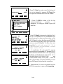
3. Press F2:[DEL]to delete a file for the
instrument.deleting
operation
is
dangerous ,for safty,you should export the
data first.
File
4. Press F3:[Read] to browse the highlight file.if
the file is coordinate file or measurement file
then the record is shown as the picture on the
left.F1:[Begin] to show the first record.F4:[End]
to show the end record.F2:[PgUp] to show the
previous record.F3:[PgDn] to show the next
record.[★] to edit the record if ‘*’is
on the interface.only point name ,code and
height can be edited.
5. A coordinates file and code file can be
imported from the peripheral PC through RS232
serial interface.the Baud ratio is set by pressing
F1:[Fast] or F2:[Slow],the baud ration set is
2400,4800,9600,19200,38400,57600
and
115200,another config is no parity ,1 start bit
and 1 stop bit.after you select filename you can
press F4:[Import] to perform the convection.
Export
6. Measurement file can be exported from the
RS232,the operation is same as the Importing
56/62
--Fileman--
Warning!
1.Fileman
2.Import
Format will lose data
3.Export
ENTContinue
4.Disk format
ESCQuit
5.Disk information
6.Input coordinate
▲
▼
--Fileman--
1.Fileman
2.Import
Availability space
3.Export
2004KB
4.Disk format
5.Disk information
6.Input coordinate
▲
7. Sometimes, many files have been saved in
the instrument,it will take a long time to delete
these files one by one.formating the disk would
be a good idea,when you format the disk,the
prompt as the picture on the left will appear.so
you must save all measurement data before you
format.
8. Sometimes, you wish to view the fress space
of the disk. You can select the menu item 5 to
do it.
▼
Pt.name SUN9
Code:
MY
N:
111
E:
222
m
Z:
21
B.S. Clear Num. Enter
9. Sometimes, you need to previously input
some coodinates for the subsequent using.
Then you can use the menu item 6 to input
data.
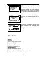
17. Specifications
Telescope
Image Erect
Objective aperture (EDM) Ф45mm
Magnification 30×
Field of view 1°20′
Resolving power 3.5″
Minimum focus distance 1.5 m.
Angle measurement
Detecting system absolute encoder
Angle unit degree/gon/mil, selectable
Minimum display 1″ / 5″ / 1 0 ″ , s e l e c t a b l e
Detecting mode Horizontal: double, Vertical: double
57/62
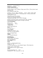
Accuracy 2″ ( D I N 1 8 7 2 3 )
Distance measurement
Distance unit m/ft, selectable
Working distance (good condition) Single prism 2000 m, 300m @white board
reflectivity 18%
Mini-reading Fine mode 1mm
Accuracy ±(2mm+2ppm·D)@prism ; ±(5mm+3ppm·D)@no prism
Measurement time Fine mode: 2 sec @single mode; 1.2sec @continue mode
Tracking mode: 0.5 sec
Temperature unit ºC/ºF, selectable
Pressure unit hPa/mmHg, selectable
Temperature input range -20ºC to +60ºC (1ºC steps)
Refraction and earth curvature correction OFF/0.14/0.2, selectable
Reflecting prism constant correction -99.9mm to +99.9mm
Level vial sensitivity
Plate level 30″ /2mm
Circular level 8′ /2mm
Compensation
System Liquid single axis
Range ±3′
Resolving power 1″
Laser plummet
Accuracy ±0 . 8 m m / 1 . 5 m
Laser class Class 2/I EC60825-1
Laser wavelength 650nm
Display
LCD 6 lines×24 characters
Illumination Yes
Internal memory
Internal memory 20000 points
Data communication
I/O RS-232C
Power
Battery Li-ion Rechargeable battery
Voltage 7.4V DC
Continuous operation tine ~9 hrs Distance & angle, ~24 hrs Angle only
Chargers 100V to 240V 50/60Hz
Charging time (at +20℃) Approx. 4 hours
Others
Working temperature -20°~+50℃
Dimension 220×184×360mm(W×D×H)
58/62
Weight 14 lb.
Waterproof IP54 (IEC60529)
18. Prompt,Warning and Error Messages
" Tilt Over"—the tilt compensater is out of range
“Points NO.<=20”—the number of points should be less than 20
"Cannot find"—cannot find any point by the name
"Pt. first"—input the name of point first please!
"No information"—Have not got station, BSS or other coordinates,or
have not input pointname
"Filename error"—illegal character in the filename
"Cannot import"—type of the file is not match, cannot import
"Choose file"—please assign a file to import or export
"None record"—there is not record in the file
"Saved"—records have been saved
"Select coor.file"—assign a coordinates file
" Overtop"—the value is out of range
"No data"—there is not record in the file
"Type not matching"—the type of file is not match with what you need
"Inexistence file"—file is not existing
"Empty file"—there is not record in the file
59/62
"Pickup 21 records"—read out 21 roadway elements from the file
"Pickup 7 records"—read out 7 roadway I.Ps from the file
"90°Beep off"—switch off Beep on rectangle position
"90°Beep on"—switch on Beep on rectangle position
"Setup station first"—please config station before seting BSS
"Open error"—cannot open file
"T.H. overtop"—the height of the prism is out of range
"I.H. overtop"—the height of the instrument is out of range
"Dist overtop"—the value of distance is out of range
"Press overtop"—the value of air pressure is out of range
"temp. overtop"—the value of air temperature is out of range
"Cannot calculate"—the shape is mussy,so area cannot be calculated.
"Extension error Input as follow (COD,COO,MEA,LSH,LSV)"
—system can only accept some file such as:*.cod,*.coo,*.mea,*.lsh,*.lsv
_
" Disk is full"—there is not enough space to save file,delete some
unused file.
"Max elements should be less than 20!"—there are 20 or less elements
that can be accepted by the instrument.
"Mileage overtop! "—the mileage of the start point is out of range
"Error:I.P number less than 3!"—for calculation ,the number of the
60/62
intersection point should be 3 or more
"No data(V)!"—there is not data that define the roadway in vertial
aspect
Standard Warranty Terms
Warranty period for NTS02 is 24 months from date of purchase.
NWI warrants this instrument made by Northwest Instrument to be free from
manufacturing defects in materials and workmanship. For claims to be made under
this warranty, the instrument must be inspected by Northwest and the defect must be
proven to NWI’s satisfaction. At the time that it is proven to the NWI’s satisfaction
that the instrument is defective, it shall be repaired or replaced, at the NWI’s option
and returned to the original purchaser at no cost to them. NWI’s sole obligation and
the Buyer’s sole remedy are limited strictly to repair or replacement with these
provisions below:
A. The instrument is returned to Northwest, properly packaged with the transportation
charges prepaid and insured and accompanied by proof of ownership. Receipt and
previous registration is required.
B. Except for ordinary wear and tear resulting from normal usage, the instrument,
upon inspection by NWI is determined to be defective in material and/or
workmanship.
Under no circumstances shall NWI be liable for any consequential, incidental or
contingent damages whatsoever.
Limitations and Exclusions
A. This warranty does not apply to instruments subject to negligence, abuse, accident,
improper operation, instruments damaged in transit or damage due to unauthorized
service repairs made by someone other than Northwest or other Northwest authorized
service personnel. Circumstances beyond Northwest Instrument s control cannot be
warranted.
B. This warranty does not apply to regular required maintenance such as cleaning,
adjusting, lubricating or calibrating unless required as a result of a defect in
workmanship or materials. If, upon examination of the instrument, NWI determines
that additional repair services are required and not covered under this warranty, NWI
shall notify the Buyer of such repair charges and proceed only after authorization has
been received.
C. This warranty does not apply to instruments damaged in transit to or from
Northwest Instrument or any authorized repair center.
61/62
Other remedies may or may not be available for transportation damages.
These designs, figures and specifications of NTS02 are subject to change without
notice. NWI shall not be held liable for damages resulting from errors in this
instruction manual.
62/62