1
CANopen Basic
PL7, Premium, Micro, Advantys
System Manual Document
Inclusive Example Source Code
Table of Content
System .....................................................................................................................................3
Architecture.............................................................................................................................3
Installation...............................................................................................................................4
Hardware .............................................................................................................................................................5
Implementation .....................................................................................................................10
Software Configuration......................................................................................................................................11
Debugging .........................................................................................................................................................20
Addendum .............................................................................................................................22
More than 4 PDOs required for a node .............................................................................................................22
Basics of CANopen ...........................................................................................................................................24
Introduction
The System Manual Document is intended to be a “Quickstart Manual for a System” for setting
up a CANopen network on a Premium or Micro PLC..
It´s intention is not to replace any product documentation.
Instead it will deliver all the information needed on top of the product documentation to install,
parameterize and start-up the outlined system.
The functional description or specification of a specific user application is not part of this manual.
It is intended to support customers being not familiar with CANopen on their first steps to set up
CANopen devices on a Premium or Micro PLC.
It will explain how to set up the hardware and which software tools must be used for which
purpose during the process of software configuration. Default settings are kept wherever it is
possible to facilitate the way through the configuration process and to prevent the user from
loosing his orientation inside this guide.
CANopen Basics - Oct-04
Schneider Electric
1
Abbreviations
Word / Expression
PLC
HMI
VVD
PC
AC
DC
PS
I/O
CB
ESTOP
Premium
Micro
Phaseo
Magelis
Altivar
Telefast
CANopen Basics - Oct-04
Signification
Programmable Logic Controller
Human Machine Interface
Variable Velocity Drive
Personal Computer
Alternating current
Direct current
Power supply
Input / Output
Circuit Breaker
Emergency Stop
The generic range name for a Schneider midrange PLC
The generic range name for a Schneider midrange PLC
The generic range name for the Schneider power supply devices
The generic range name for all the Schneider HMI devices
The generic range name for all the Schneider VVD devices
The generic range name for the Schneider distributed I/O devices
Schneider Electric
2
System
Introduction
The system chapter describes the architecture, the components, the dimension and
the amount of components used within this system.
Architecture
Overview
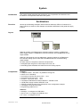
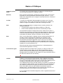
We set up the following CANopen network with two Advantys STB on a Premium PLC.
Note: Premium is chosen for this example, but all that is described in this guide also apply
to Micro.
Layout
Node #2
Node #3
Node #2 consists of a STBNCO2212 CANopen interface module, a STBPDT310
power supply module, a STBDDI3410 4 bit input module, and a STBDDO3410 4 bit
output module.
Node #3 is like Node #2, but has additionally 2 analog modules, the STBAVI1270
two channels analog input module and the STBAVO1250 two channels analog
output module.
For both nodes, the outputs are wired to the inputs then:
• the digital input one goes on when output one is set, etc ...
• the analog inputs read back the value set from the analog outputs
Components
Hardware:
• CANopen master : TSX CPP 110 (PCMCIA card type III,
• DS 301 V4.01 standard)
• On Premium P572xxx to 574xxx: CPU V5.0
• On Premium P571xxx: CPU V5.6
• On Micro : CPU (TSX 372x) V6.0
• 2 CANopen STB Network Interface Modules : STB NCO 2212
• 2 STB power supply modules STB PDT 3100
• STB I/O modules as listed in the description of the configuration example
• 3 CANopen connectors and cable
• Programming cable for PLC
Software :
• Advantys : to configure the STB island
• SyCon V2.8 : to configure the CANopen bus
• PL7 V4.4 : to configure the PLC
CANopen Basics - Oct-04
Schneider Electric
3
Installation
Introduction
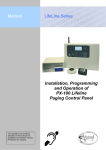
This chapter describes the step necessary to install the hardware and to setup the
software to fulfill the following application architecture.
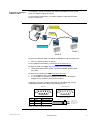
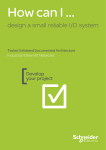
Layout
ERNI 103643
103668
Lapp 2170261
Node 3
Node 2
CANopen Basics - Oct-04
Schneider Electric
4
Hardware
General
• Assemble the modules incl. wiring and hardware settings (baud rate, network
address, ...)
• Assemble the Premium PLC incl. TSX CPP 110 (for this example)
• Prepare and install the CANopen cable
Assemble the STB
devices
Connect the STB hot swap bases and mount the modules in the sequence
listed below. Changing the sequence of the I/O modules has an impact of
the I/O addresses in the state RAM of the PLC.
Step 1
Assemble the modules
Node #2:
Node #3:
Network interface STBNCO2212
Power supply STBPDT3100
Digital input module STBDDI3420
Digital output module STBDDO3410
Termination plate STBXMP1100
Network interface STBNCO2212
Power supply STBPDT3100
Digital input module STBDDI3420
Digital output module STBDDO3410
Analog input module STBAVI1270
Analog output module STBAVO1250
Termination plate STBXMP1100
Step 2
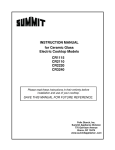
Field wire the devices
Wire the Advantys STB. The following illustration is showing the wiring of
Node #3. The wiring of Node #2 is similar (only the last two modules are
missing)
Note that we recommend to have a separate power supply for the outputs.
For testing purpose, however, you can have one common power supply for
inputs, outputs and logic supply (as shown in the figure above).
CANopen Basics - Oct-04
Schneider Electric
5
Step 3
Set up the CANopen
baud rate to 250 Kbit
Both baud rate and node address are set with the two rotary switches in the
middle of the NCO module.
To set the baud rate, proceed as follows :
1. Check that the power is off
2. Set the upper rotary switch (TENS) to position 4
3. Set the bottom rotary switch (ONES) to “Baud Rate” (= any
position after 9)
4. Power on
Note that the baud rate will be taken into account after power on and only
when the bottom rotary switch is on position "Baud Rate". The baud rate is
selected with the upper rotary switch (0 = 10 Kbit, 1 = 20 Kbit, 2 = 50 Kbit, 3
= 125 Kbit, 4 = 250 Kbit, 5 = 500 Kbit, 6 = 800 Kbit, 7 = 1 Mbit).
Step 4
Set up the CANopen
node address
The node address is set with the same two rotary switches:
1. Check that the power is off
2. Select 0 on the upper switch (TENS)
3. Select 2 on the lower switch (ONES) for the module with the CANopen
address 2 and 3 for the module with the CANopen address 3
4. Power on
Note: The 2 switches represent the address value. For a CANopen address
of 16: select 1 on upper switch (TENS) and 6 on lower switch (ONES).
Note that the node address will be taken into account only after power on.
When changing the address without a power cycle, the module will keep the
old address until the next power cycle takes place.
Step 5
Load the Advantys STB
configuration
Use the Auto-Configuration feature (no SIM card) of the NCO module as
follows:
1. Check that the power is on and remove the SIM card if inserted
2. Press the reset button which is located under the door in the bottom of
the NCO module for about 5 seconds
Now the Advantys STB is booting. The hardware configuration is read from
the backplane and stored into a flash memory.
Note that an Advantys STB is always trying to load the configuration from
the SIM card. When no SIM card is inserted, the configuration is taken from
the flash. When the current configuration is different from the one in the
flash, push the reset button to update the flash. Always push the reset
button after a configuration change or when the flash configuration is
unknown.
CANopen Basics - Oct-04
Schneider Electric
6
Step 6
Last check
Now the Advantys STB is properly set up and the devices are ready to
communicate with the CPP110 CANopen master.
The LEDs must show the following status:
• NCO module: "RUN" and "PWR" are set to on, "CANRUN" is blinking
• PDT module: "IN" and "OUT" are set to on
• I/O modules: "RDY" is set to on, on every I/O module
Possible Errors
Configuration mismatch
When the configuration in the flash is different from the actual configuration,
the LED status is as follows:
•
•
•
Module Error
CANopen Basics - Oct-04
NCO module: "RUN" and "PWR" are set to on, "CANRUN" is blinking
green, "ERR" and "CANERR" are blinking red
PDT module: "IN" and "OUT" are set to on
I/O modules: "RDY" is blinking on every module which does not match
with the configuration from flash, "RDY" is on for every other I/O module
Some modules can display an error condition (e.g. DDO3230, when output
voltage supply is missing). In this case, "RDY" is on and "ERR" is blinking
on the module, while the NCO module is healthy ("RUN" and "PWR" are set
to on, "CANRUN" is blinking).
Schneider Electric
7
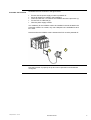
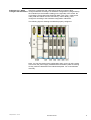
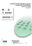
Assemble the Premium
Assemble the PLC as shown in the figure below.
•
•
•
•
•
Ensure that the power supply module is powered off
Mount all Premium modules in the backplane
Insert the TSX CPP 110 card into the PCMCIA slot of the processor (1)
Fix the TAP on a DIN rail (2)
Wire the power supply module
It is mandatory for the PCMCIA card to be installed in the slot located in the
processor module. As a result, only one CANopen bus is available for each
PLC CPU.
Note that when the PCMCIA card is inserted the PLC must be powered off.
1
2
Now the Premium is properly set up and can be powered on and software
configured.
CANopen Basics - Oct-04
Schneider Electric
8
Prepare and install the
CANopen cable
For CANopen, special connectors and cable are available from the market
(refer to CANopen cabling document).
For the present configuration, you need to prepare a cable with 3 female
SUB D 9 connectors:
ERNI 103643
103668
Lapp 2170261
Node 3
Node 2
Example of CANopen cable is available by Selectron under the product ref:
• DCA 701 (article number 44170014)
For any additional information, consult http://www.selectron.ch/
Example of cable from Lapp: http://www.lappcable.com/products/
• UNITRONIC BUS CAN 2170261: 120 Ohms shielded double twisted
pair cable
Example of connectors from ERNI: http://www.erni.com/
• 1 x ref 103668 for daisy chain (plugged on Node 2)
• 2 x ref 103643 for the end of the bus (includes the line termination;
plugged on the TSXCPP110 tap and on Node 3)
CANopen connectors normally have screw type terminals and must be
assembled manually, according to the following pin out:
Male (pins)
1
2
6
Pin N°
Signal
3
7
Female (sockets)
4
8
5
9
Description
2
CAN_L
CAN_L bus Line
3
CAN_GND
CAN ground
7
CAN_H
CAN_H bus Line
5
4
9
3
8
2
7
1
6
Shield (to the connector)
Can L (to pin 2)
Can H (to pin 7)
Can GND (to pin 3)
Not connected
Pin 2, 3, and 7 must be connected.
CANopen Basics - Oct-04
Schneider Electric
9
Implementation
Introduction
The implementation chapter describes all steps necessary to initialize, parameterize,
program and to Start-Up the system.
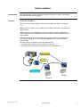
Function
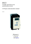
Functional description
We set up the following CANopen network with two Advantys STB on a Premium
PLC.
Note: Premium is chosen for this example, but all that is described in this guide also
apply to Micro.
Node #2 consists of a STBNCO2212 CANopen interface module, a STBPDT310
power supply module, a STBDDI3410 4 bit input module, and a STBDDO3410 4 bit
output module.
Node #3 is like Node #2, but has additionally 2 analog modules, the STBAVI1270
two channels analog input module and the STBAVO1250 two channels analog
output module.
For both nodes, the outputs are wired to the inputs then:
• the digital input one goes on when output one is set, etc ...
• the analog inputs read back the value set from the analog outputs
ERNI 103643
103668
Lapp 2170261
Node 3
Node 2
CANopen Basics - Oct-04
Schneider Electric
10
Software Configuration
Introduction
The software configuration consists of three major steps:
1. Create the Advantys STB configuration and generate an EDS file for each node
(Advantys software)
2. Create the CANopen configuration (SyCon software)
3. Create the PLC application (PL7 software) and transfer the project to the PLC.
Hereafter, the whole system is running and you can write outputs to / read inputs
from the CANopen devices.
Create the Advantys
STB configuration
The main purpose of the Advantys tool is:
• To modify the default parameters of the I/O modules (i.e. switching off
behavior of outputs, ...)
• To load the Advantys configuration into the SIM card (if any)
• To generate the EDS files
As we work in our example with the modules’ default settings and we
already have loaded a configuration from flash (refer to section Hardware
configuration), we only use this tool to generate an EDS file for each of our
nodes. These EDS files are providing all information on the nodes needed
by SyCon to configure the bus.
Note that the Advantys tool is not mandatory. You can also use the generic
EDS file, which is available in SyCon. This, however, requires deeper
CANopen knowledge and advanced usage of the SyCon software. EDS
files created from the Advantys software are dedicated to the individual
configuration of each node and reduce the configuration work to a minimum.
Note: In case you want to load the configuration through the Advantys tool,
use the menu Online/Connect then Online/Download into the island (in this
case, specific cable is required).
Steps to create the
Advantys configuration
Advantys tool - Step 1
Create a new workspace
Start the Advantys tool, create a new workspace and enter name and path.
In our example, we have chosen the path D:\Advantys_Projects\Quick Start.
The name of the project file is Quick Start.aiw and the name of the Advantys
STB is Node_2 (referring to its CANopen node address). All the Advantys
STB on the same bus must be declared in the same workspace. Default
workspace path is C:\program Files\Schneider Electric\Advantys\Project\
CANopen Basics - Oct-04
Schneider Electric
11
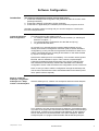
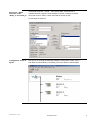
After that, a workspace with a DIN rail for Node #2 is opened. Now
Advantys tool - Step 2
Configure the STB nodes configure Node #2 according to its hardware configuration by drag and drop
the modules from the hardware catalog on the right side of the screen. Do
not forget the Termination plate (Ref STB XMP 1100). Then, create a new
node (“Add new Island” from the “File menu”), name it Node_3 and
configure it according to the hardware configuration of Node #3.
The following figure is showing the Node #3 properly configured.
Note: You can also read out the configuration when you are in online mode.
In this case, the power supply module and the termination plate are missing
as they cannot be detected on the island’s backplane. You must add them
manually.
CANopen Basics - Oct-04
Schneider Electric
12
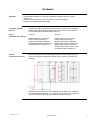
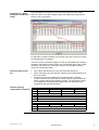
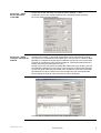
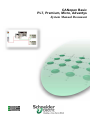
Advantys tool - Step 3
Display the Fieldbus I/O
image
Open the fieldbus I/O image from the menu I/O image overview. Select
Node #3, click on the TAB “Fieldbus image” and select PDO alignment as
shown in the screen below.
Do the same for Node #2. Make a print screen from both screens as it helps
to understand the IO mapping.
In the PLC memory, Node #3 assigns 3 words of output data and 5 words of
input data. The table is read as follows: You can find the input of slot 1 (DDI
module) in the input word 1 (low byte), the I/O of slot 2 (DDO module) in
input word 1 and output word 1, .....
General mapping rules
are:
•
•
•
Detailed mapping
interpretation of Node #3
CANopen Basics - Oct-04
First a block with discrete I/O, then the block with analog I/O
Within the blocks, the I/O points are sorted by the physical sequence of
the I/O modules.
Discrete I/O points are mapped into the discrete block, sorted by
number. First the I/O points, after, the echo (outputs only) and then the
status. Analog channels are sorted by number. The input/output values
are mapped into the analog input/output block, the status bytes are
mapped into the discrete input block.
Input Data
15..12
11..8
7..4
3..0
Word
Status
bitsslot
2
Echo
bitsslot
2
Status
bitsslot
1
Input
bitsslot 1
1
2
Status bytes- slot 3
Status bytes- slot 3
3
Status bytes- slot 4
Status bytes- slot 4
4
Input channel - slot 3
5
Input channel - slot 3
Output Data
15..12
11..8
7..4
3..0
Word
Output bits- slot 2
1
2
Output channel- slot 4
3
Output channel- slot 4
Schneider Electric
13
Advantys tool - Step 4
Create the EDS files
Select node 2 and create the EDS file by “File” ->”Export ...”. Select
“Node_2” as name for the EDS file.
Do the same for node 3.
In our example the files will be exported on the following directory :
D:\Advantys_Projects\Quick Start\*.eds.
Now the Advantys STB configuration is complete. You have generated the
EDS files as output and you are now ready to start the CANopen
configuration with SyCon.
Create the CANopen
configuration
With the CANopen configuration, we generate an electronical description of
the CANopen fieldbus. This description contains all information that PL7
needs to configure the CPP110 CANopen master.
Perform the following steps:
SyCon tool - Step 1
Create a new SyCon
project
Start the SyCon tool (it can be opened from the PL7 configuration screen,
see: PL7 tool – Step 1) and open a new CANopen project. Save the empty
project as ...\Demo_cfg.co. The default path is ...\SyCon\Project\.
You will have to know the path and the filename as PL7 needs it during the
PLC configuration.
SyCon tool - Step 2
Import the EDS files
From Menu "File" then "Copy EDS", Copy the EDS files node_2.eds and
node_3.eds you have generated with the Advantys tool. Refuse the import
of the bitmap file (those files don’t exist). Files to be imported are localized
in this example into the following directory (refer to Advantys tool - Step 4) :
D:\Advantys_Projects\Quick Start\*.eds.
SyCon tool - Step 3
Insert the TSX CPP 110
Insert the CANopen master TSX CPP 110 (Insert -> Master ...).
Keep the node address #1. SyCon is offering as a default value.
CANopen Basics - Oct-04
Schneider Electric
14
SyCon tool - Step 4
Insert the nodes
“Node_2” and “Node_3”
Insert Node #2 (Insert -> Node ... and choose Node_2 from the list of
available devices). Keep the node address #2 SyCon is offering as default
value then click on "Add>>" button and valid the screen by OK.
Do the same for Node #3.
Configuration screen in
SyCon
CANopen Basics - Oct-04
Now SyCon is showing the following CANopen configuration screen. SyCon
has taken the names Node_2 and Node_3 from the names of the EDS files.
Schneider Electric
15
SyCon tool - Step 5
Set the Baud rate
to 250 kBit
Simple click on the TSX CPP 110 and then select “Settings” -> “Bus
Parameter” in the menu. Adapt the Baud rate to 250 kBit/s (value previously
set on the Advantys STB hardware.).
SyCon tool - Step 6
Configure the PDOs for
Node #2
Double click on Node_2. The Node configuration screen opens and is showing
two PDOs in the “Predefined Process Data” grid. The first PDO is a Receive-PDO
(RxPDO) to configure the output data for Node #2, the second is a Transmit-PDO
(TxPDO) to configure the input data from Node #2. (The transmission direction is
always seen from the node’s point of view.)
Double click on the first PDO and validate the transmission type window. (We use
the predefined settings from this screen.) Now you have configured the first PDO
SyCon has got all necessary information from the EDS file you have created with
the Advantys tool. Do the same for the second PDO and you have finished the
PDO mapping for Node #2. Now the screen is looking as follows:
Click on "OK" to valid and close the node configuration window.
CANopen Basics - Oct-04
Schneider Electric
16
SyCon tool - Step 7
Configure the PDOs for
Node #3
Do the same with Node #3. For Node #3, SyCon is offering four predefined
PDOs, two Receive PDOs and two Transmit PDOs.
•
•
•
•
RxPDO1 is defining the PLC digital output data
RxPDO2 is defining the PLC analog output data
TxPDO1 is defining the PLC digital input data
TxPDO2 is defining the PLC analog input data
Configure all 4 PDOs in the same way as you did it with Node #2.
Warning: You have to map all offered PDOs and perform no changes on
these PDOs, otherwise your I/O mapping in PL7 doesn’t correspond to the
address table from Advantys tool.
By default, the transmission of analog input values is disabled on the
SyCon tool - Step 8
modules. Perform the following steps to enable analog input transmission:
Enable analog input
transmission for Node #3
1. Open the Node configuration window for Node #3
2. Press on the Object Configuration button
3. Double click on the object 6423 : Analog Input Global Enable in the list
of Predefined supported Objects
4. Enter 1 in the Chosen Value to validate the analog input
Close the window and save the project. You have now finished the
CANopen configuration with SyCon and created all necessary data PL7
needs to configure the TSX CPP110 module.
The information is available in a database, the default path for our example
is ....\SyCon\Projects\demo_cfg.co.
You are now ready to start with the PL7 application.
CANopen Basics - Oct-04
Schneider Electric
17
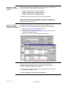
Create the PL7
Application
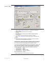
PL7 tool – Step 1
1
2
4
5
3
Start PL7, create the hardware configuration and double click on the
PCMCIA slot of the CPU
1. Select the Channel 1
2. Select the TSX CPP100 - 110 card
3. Define the output behavior in case of PLC stop: Maintain or Reset
By default:
4. “Mast” task is selected as rate of update of the storage area associated
with the I/O
5. “Automatic” bus start up mode is selected
Note that SyCon tool could be launched from this screen.
CANopen Basics - Oct-04
Schneider Electric
18
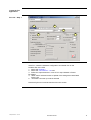
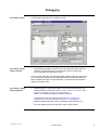
PL7 tool – Step 2
2a
2b
1
4
3
1. Click on Select Database to import the *.co file into PL7 (example :
Demo_cfg.co)
2. Define the addresses of the Inputs and Outputs:
Example:
• 2a : Inputs: Array of 32 words (from %MW0 to %MW31) We keep
default values.
• 2b : Outputs: Array of 32 words (from %MW50 to %MW81).
3. Press on Bus configuration to see the list of nodes configured on the
bus.
By default:
4. “PL7” mode is selected to have the CANopen configuration loaded
together with the PL7 application into the PLC
Close the window, confirm all changes and save the project. You have now
finished the PLC application with PL7 and created all necessary data the
PLC needs to start the communication with the CANopen nodes.
You have now reserved 32 words as well as for inputs than for outputs. The
input words start at %MW0, the output words at %MW50. As Node #2 is
using one input word and one output word and Node #3 five input words
and three output words, we have the following address assignment:
• Inputs Node #2:
%MW0
• Outputs Node #2: %MW50
• Inputs Node #3:
%MW1 to %MW5
• Outputs Node #3: %MW51 to %MW53
(Refer to Advantys tool – Step 3)
Transfer the application to the PLC and start the program.
CANopen Basics - Oct-04
Schneider Electric
19
Debugging
PL7 Debug Screen
For debugging open the CPP110 debug screen
1
3
2
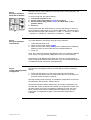
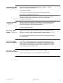
PL7 Debug - Step 1
Node overview
1. The node list provides an overview over all configured nodes. Node #2
is shown in red because it is not connected to the bus. Node #3 is
working properly and therefore is black.
If one or more nodes are red, the DIAG button (and the CPP error led) is red
too. The Premium resets error led and DIAG button automatically when the
faulty condition has gone. For the TSX Micro, it must be reset by a positive
edge on bit %QW0.1:X2.
PL7 Debug - Step 2
Node diagnostic
2. Node diagnostic. To get more details, click on the red listed node. The
diagnostic field is showing the string : Node 2: Status=01h, AddInfo=0000h,
Profile=0, NodeState=127, Error= 34, EmcyEntries= 0
Status = 01 indicates that Node #2 does not answer.
The diagnostic string of Node #3 is showing Node 3: Status=08h,
AddInfo=0015h, Profile=401, NodeState=5, Error= 0, EmcyEntries= 0
Status=8 indicates that the node is controlled by the TSX CPP 110.
For more details refer to the TSX CPP 100/110 user manual.
CANopen Basics - Oct-04
Schneider Electric
20
PL7 Debug - Step 3
Set I/O points
3. Set output word %MW51 to 16#000F, all four outputs will go on. You
can see the echo of the outputs in the MSB (Most Significant Byte) of
%MW1. As the outputs are wired to the inputs, you also see the inputs
in the LSB (Less Significant Byte) of %MW1 too.
Set output word %MW52 and %MW53 to 16000 (=16#3E80). The
output channels put out 5 VDC and feed them back to the analog input
channels. You can read this value back in the input words %MW4 and
%MW5 (by using the scroll bar).
Input word %MW2 is containing one Status byte for each of the two
analog input channels, Input word %MW3 the Status bytes for the two
analog output channels.
Refer Advantys tool - Step 4, where I/O mapping is described.
CANopen Basics - Oct-04
Schneider Electric
21
Addendum
More than 4 PDOs required for a node
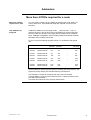
More than 4 PDOs
required for a node
You can simply configure up to 4 PDOs per direction per node. When you
want to have more, some additional steps are required. This due to the
following:
How COB-Ids are
assigned
COB-Ids for PDOs are in the range of 385 ... 1407 (hex 180 ... 57F). In
general, the user is free in the choice of the COB-ID for a given PDO. But
he has to take care to stay in this range and he should not use a COB-ID
twice. CANopen configuration tools normally provide an automatic COB-ID
allocation which is taking care of this.
Sycon is using the following algorithm which is in accordance with profile
301:
1. TxPDO
1. RxPDO
16#180+Node-ID
16#200+Node-ID
Node #1
(decimal)
385
513
Node #2
(decimal)
386
514
.....
.....
.....
Node #127
(decimal)
511
639
2. TxPDO
2. RxPDO
16#280+Node-ID
16#300+Node-ID
641
769
642
770
.....
.....
511
895
3. TxPDO
3. RxPDO
16#380+Node-ID
16#400+Node-ID
897
1025
898
1026
.....
.....
1023
1151
4. TxPDO
4. RxPDO
16#480+Node-ID
16#500+Node-ID
1153
1281
1154
1282
.....
.....
1279
1407
As the COB-ID is determining the priority of a frame (the lower the ID is, the
higher the priority will be), this has the following consequence:
The first PDO of a node is more prior than the second or the third
Transmit PDO1 is more prior than Receive PDO1, Transmit PDO2 is more
prior than Receive PDO2, ...
The lower the node ID is, the more prior PDOs will be.
CANopen Basics - Oct-04
Schneider Electric
22
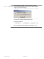
Steps to configure PDO5 Note that the range for COB-IDs allows each node to have 4 Transmit
PDOs and 4 Receive PDOs. A 5th PDO cannot get its COB ID automatically
as there are no more free numbers left.
Configure PDO5 in the Node configuration screen of Sycon. The following
window opens:
Disable the automatic COB-ID allocation (node configuration screen). Now
you can manually overwrite the COB-ID for PDO5, PDO6, ...
Use the following COB-IDs:
•
•
Transmit PDO 5, 6, ...
Receive PDO 5, 6, ...
in the range of 1664 ... 1759 (Hex 680 ... 6DF)
in the range of 1761 ... 1792 (Hex 6E1 ... 700)
Now you can close the node configuration screen and save your project.
CANopen Basics - Oct-04
Schneider Electric
23
Basics of CANopen
CANopen specific
terms
The following terms and abbreviations are helpful for understanding the
communication principals in a CANopen network.
EDS files
EDS = Electronic Data Sheet. An EDS file is describing the communication
properties of a device (baudrates, transmission types, I/O offer, ...). It is
used in the configuration tool to configure a node (like a driver in a Windows
operating system).
CO files
*.CO files are configuration files generated by the SyCon tool. They are
imported into PL7 and contain all necessary information the TSXCPP110
needs to configure the CANopen nodes and to exchange I/O data.
PDO
PDO = Process Data Object. CANopen frame containing I/O data. We
distinguish between:
• Transmit-PDOs (TxPDOs with data provided by a node) and
• Receive PDOs (RxPDOs with data to be consumed by a node).
The transmission direction is always seen from a node’s point of view. A
PDO does not necessarily contain the whole data image of a node (for both
TxPDO and RxPDO). Normally, analog input data and discrete input data
are divided onto different TxPDOs. The same is true for outputs.
SDO
SDO = Service Data Object. CANopen frames containing parameters. As
the data of PDOs is automatically handled by the CANopen nodes
(according to the configuration in SyCon) SDOs must be launched by
function blocks through the application. As we can set up our example
configuration without using SDOs, for further explanation refer to the TSX
CPP100/CPP110 user manual (reference TSX DM CPP100/110 CAN open,
available on PL7 documentation CD).
SDOs are typically used to read parameters from / write parameters to
drives while the application is running.
Transmission Types
CAN open frames can be either sent cyclically, on change of state, or on
remote request. For each PDO you can define a transmission type (in
SyCon). This reduces the network load. (In this guide we use the default
settings and do not go deeper into this subject. For more information refer to
the TSX CPP100/CPP110 user manual).
COB-ID
COB-ID = Communication Object Identifier. Each CANopen frame starts
with a COB-ID and plays herewith the role of the Identifier in a CAN frame.
During the configuration phase each node is receiving the COB-ID(s) for the
frame(s) he is providing and for the frames he has to consume.
In a CANopen PDO you won’t find the node ID of a provider or consumer as
it is common for other networks. This role is taken over by the COB ID and
this enables to spread the I/O image of a node over more than one PDO.
Each of this PDO can be sent with a different transmission type and
different priority. This also enables to have more than one consumer for a
PDO (they only have to be sensitive to the same COB-ID).
For more details about COB-IDs assignment, refer to Appendix at the end of
this document.
CANopen Basics - Oct-04
Schneider Electric
24
Contact
Author
Schneider Electric GmbH
Customer & Market
System & Architecture
Architecture Definition Support
Schneider Electric GmbH
Steinheimer Strasse 117
D - 63500 Seligenstadt
Germany
CANopen Basics
Telephone
+49 6182 81 0
e-mail
[email protected]
As standards, specifications and design change from
time to time, please ask for confirmation of the
information given in this publication
Oct-04