1
US 20100203888A1
(19) United States
(12) Patent Application Publication (10) Pub. No.: US 2010/0203888 A1
(43) Pub. Date:
Gunaratnam et al.
(54)
DATA-CAPABLE NETWORK
(60)
?led on Nov. 12, 2003.
Publication Classi?cation
Jayasri Gunaratnam, Waterloo
(CA); Noushad Naqvi, Waterloo
(CA); Bryan Taylor, Kitchener
(CA); Craig Ian Haight SWann,
Waterloo (CA); Hugh Hind,
Waterloo (CA); Bao Quoc Nguyen,
San Diego, CA (U S); Darcy
Richard Phipps, Waterloo (CA)
Int. Cl.
H04W 60/00
(52)
us. c1. ................................................... .. 455/4352
(2009.01)
ABSTRACT
Reject code handling is utiliZed for a more time-ef?cient
selection of data-capable networks. One illustrative method
for use in selecting a wireless communication network for
communications involves the steps of selecting a ?rst wire
less network available for communications with the mobile
station; causing a request for data connectivity to be trans
mitted to the ?rst wireless network selected; if a rejection is
received from the ?rst wireless network in response to the
Correspondence Address:
ni?cent Mile Center
Chicago, IL 60611 (US)
RESEARCH IN MOTION
request for data connectivity: reattempting the request for
LIMITED, Waterloo (CA)
data connectivity to the ?rst wireless network at least one
time; selecting a second wireless network available for com
munications with the mobile station after the request for data
connectivity to the ?rst wireless network is reattempted the at
least one time without success; and selecting the second wire
less network available for communications with the mobile
(21) App1.No.:
12/704,699
(22) Filed:
Feb. 12, 2010
station without reattempting the request for data connectivity
Related US. Application Data
(63)
(51)
(57)
John J. Oskorep, Esq. LLC
980 North Michigan Avenue, Suite 1400, One Mag
(73) Assignee:
Provisional application No. 60/519,150, ?led on Nov.
12, 2003, provisional application No. 60/519,141,
PRIORITIZATION WITH REJECT CODE
HANDLING
(75) Inventors:
Aug. 12, 2010
to the ?rst wireless network the at least one time if a reject
Continuation of application No. 11/674,738, ?led on
code associated with the rejection indicates that data services
Feb. 14, 2007, now Pat. No. 7,689,219, which is a
continuation of application No. 10/987,658, ?led on
Nov. 12, 2004, now Pat. No. 7,197,312.
are not allowed in the ?rst network is received from the ?rst
wireless network in response to the request for data connec
tivity.
Home
205
235
225
---------- “" """"""""" V
Voice
Support Only"
BAS
Local Network 4
Senf'w /
GSM IGPRS
pm‘g'der
/
212
218
(33M
Mobile
Station
,4’
BAS
Local Network 3
GSM
200
Home Network
Local Network 1
GSM / GPRS
Mobile
Station
Roams
Local Network 2
GSM / GPRS
Patent Application Publication
Aug. 12, 2010 Sheet 1 0f9
wm
mm
\ZWMEG
NN@‘ 5mm
wN<5a?n0zx<5uS
‘ 5mmEmma‘ .
US 2010/0203888 A1
-\EwQ
vmmaw‘ ‘
E,
i.
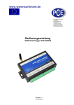
Aug. 12, 2010 Sheet 5 0f 9
Patent Application Publication
FIG. 5
US 2010/0203888 A1
Sx-vitch On Or Recevery
From Out Of Coverage
502
HPLMN i5‘ is
Net Same As
RPLMN
RPLMN Aveiiabie
And HPLMN Available And
Aliowabie. MS
Seiected Registered
PLMN
Auiomaticeiiy Select HPLMN
GSM
P:
Alteicir Reject
GSM Attach
523
_
Less Of Radio
Accepi
ei2\
Coverage Oi
v.
Seiection PLMN‘
Indicate Select
Yes
F‘LMN is Not
r
PLMN
HFQZTMN
HMTMN
imer e 6 min
5M\
User
i
Attach Reject
I
Tr} GPRS
0-)
Attach
-
PLMN Search
‘33:51:?
Time Out
534
515
518
I
On PL \‘iN
{bpRb‘
V
U
T3310 Timeout
User Reseiectiun
T
PPLMN Fwnd
RALJ Timeout
s m
T3330 or
Lower Layer
Faliure
-
- . 1
W Lass Of Radio
Deg???“
v
Netwerk
On PLMN
{GSM Oniy)
if The PLMNs is
Z
Not HPLMN
HPLMN Timeeut
542
52“
"
Time Out
HPLMN Or GPRS No
lves
(GPRS)
PD; Accept "—+
Time Out
‘7
Levi-‘er Layer Feiiure
X14‘ Try POP PUP Reed
Time’ ‘1 F“
Re-Seiection
p2
T3310 Timeout Or
GPRS Attackiqmept
Start Interns}
;
P2
Avaiiebie &
/
Aiicwabie
HF‘LMN Or GPRS l
PPLMN Found
‘
Nol
PREF =
If Either Networks Are Avaiiabie But Aiiowable
Popup Or Display: “No Aiiowebie Network
Emergency Service Oniy"
if There is No Avaiiabie Network
Pepup Or Display: “Dui Of Coverage No Service"
Wait For F‘LMNS
Registered PLMN
Tc Appear
Availebie ii Aliowabie
Pr
PLMN Aveiiable &
Aiiowabie Which is
Not RPLMN
R
sees
Sim
525
Invalid /
Patent Application Publication
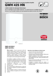
Aug. 12, 2010 Sheet 6 0f 9
US 2010/0203888 A1
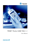
FIG. 6
631
T
Attach Reject Or
Failure Or RAU Reject
603
yes
Sim
/
616
f
Display “Data Service
Refuse {311 This Network“
P’cpup “Piease Ceniaci
Causes
7!‘! ‘$112M 3.‘
Your Service Provider”
Attach
or RAU
PLMN IS
Counter > =
HP‘EMN
\ e5
Diapiay "Data
“
654
Service Refuse 11/
On This
Newark"
Auta Scan
Any GPRS
Aiiowabie PLMN
Avaiiable
?
Dispiay "Data
Service
Temporamy
2
2
Make The PLMN List
Yes
Failure”
‘I.
606
T3362 >
Timerti Fer
PLMN S
h
Wait Fm
ears
HPLMN
Timeeug / S39
Timeout
S—P Move Last Seiected PLMN
645
Temporariiy lnio Last 0:‘! ’'
List {Not HF‘LMN}
internai Timer
?
612
608
1r
1’
HPLMN
Seiaci First / 642
Start.
'mema‘ T’me’
Timeaut
R_)
Times“
PLMN m
his!
1", f 634
V
Feundl HPLMN Or
NQ GPRS PLMN (Which
535
l
<3
or
632
K’
Start internai
l
is Not Previousiy
1"
Reject With
Start HPLMN Timer
71"i2ii31‘14)
.
?
internai Timer t1
Yes
W
Z
Patent Application Publication
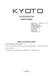
Aug. 12, 2010 Sheet 7 0f 9
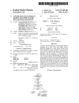
FIG. 7
US 2010/0203888 A1
(POP Deactivaiion By
Network)
7G1
U {PUP Reiect
AFN lsx N01
Stay Gr!
xnet. Or
Newark
No Emaii
‘
Appiicatinn Won‘t Try
798
No
Send Detach
Request
1
0
HPLMN
Timer >6 min
h‘ The Ermr ls Non
Criitcai Then {Dispiay
“Data Connection
Temporariiy Faiiure”) {I
713
/
Eise (Dispiay ”‘ Data
710
Connection Refuse
/
Wait For
HpLMN
star!
mama!
.
Tlmer H For
On This Network”
Time Out
PI-MN Search
Popup: "Pleaser
u
W'i
708
Perform
Auto Scan
Contact Yeur Sen/ice
Time Out
m
W2
Time out
Mme“
‘f I’ ‘
N
°
HPLMN Or
ems PLMN :
H2
A
Found '?
‘
Yes |—} 2
Start HPLMN Timer —PW1
Dr Stan t1 Timer
\
726
—} W2
"The EFT“ *5 E49“
_
n‘!
Aliowabie PLMNs
Critical Display Data
A
Connection Refused“
PDPFPLMN)
Connection Refused?’
Your Service Previdef‘} f
.! bi 0 Ih. h ._
nztafsn ii-ggelgsfg
Eise {Display “Data
Papup "Please Contact
GPRS
,?
714
'
Yes
(
Patent Application Publication
Aug. 12, 2010 Sheet 8 0f 9
US 2010/0203888 A1
Switch On!
Or Recovery From Out Of Coverage
FIG. 8
if There Is RPLMN Availabie
/
And HPLMN Avaiiabie And
Select Registered
Aiiowebie
No
L
Pnpup: “se?ec't HPLMN?
PLMN
' '7
YesiNcr"
GSM Attach Reject
F
Trying PLMN
‘
mo
68*“ Attach
Amp‘
v
G
> Seiected
indicate \
B2
|s‘My
(35M Yes
312
?
G2
Attach Re'ect
Attach
RAU Reject
V
n
RAU Timeout
2 c1
V
5“
cmée :
3'
or Selected PLMN
5‘
>
‘
‘32
em.”
' D
B3
857
Display
H
338
Yes
2,318?
“
PUP Deactivaiio
Yes
s55
'- e'ect
{ems}
Loss Of Radio Coverage
|—>
Coverage Of
Seiected PLMN
s‘
—>XZ
T3333
m
Loss 01‘ Radio
B
Tam“ “mm
PUP Reject
On PLMN UserIScan Reselection
‘
Current Seiected PLMN GSM
Gniy And Any GPRS PLMN
Becomes Availabie
5
%
5
‘GPRSY T3380 Timeout
8&6
a
B,
1%
0
5
PLMN
GPRS Attach Accept
W
_
User Reseiechgn
85D
PLMN
914
x3
852
G2
356
“Emergency Oniy“
N
'
Sim
invalid
v 826
\559
Any
PLMN
N6
Avaiiebie
333
Mg
92
?
Yes
No
Service WW"
Cance'
825
Becomes Avaiiabie
To Appear
Display: “Emergency
SeEect
lfAny PLMN
Wait For PLMN
+
_
H
n
D’
r
A“
And Wait For
Trymg Prewousiy
Avaiiableiisailziils in Order
‘ambush’ Se'eded
Seiected PLMN
And Give The 0 tiorl Te
or W?“ F“
The User To Szlect a
PLMN 56mm“
Available Again
PTQWWSW
Is No Aveiiabie
Setected PLMN
Network Display:
“No Service"
Becomes
Available
s
Th PLMN
we
839
‘_ C
a
Seiet’i PLMN
F
V
834
If The PLMIN Is FPLMN
F'opup: “Emergency Service
862
Any PLMN
Wait Fer PLMN
Becumes
Te Appear
Availabie
Seiecteci PLMN Is
FPLMN, Or Attach
Yes
Oniy!
Rej Dr POP Rej
Savefcancei“
If The PLMN is Attach Rej Or x B38
868
PDP Re}
PLMN
Previoueiy
Popup “Veice Service Only”
Seiected F'LMN
Becomes Availabie
SeveiCa ncei
GSM
Trying PLMN
Attach
|
Accept
(— G1
‘
GSM "Attach
'
F
H
G
Far?ure
B4
Patent Application Publication
Aug. 12, 2010 Sheet 9 0f 9
US 2010/0203888 A1
FIG. 9
B
Attach Reject Or
RAU Reject
9G3
Sim
Invalid
Causes
Nu
904
if The Attach Of
RAU Counter
/
914
{Display “Data Service Refuse Or: This Network?
Display "Data Service
I,’
906
P‘Qpup “Safest Network"
Refuse On This Network”
L
F
"
T33U2>§niemai
ma
‘30px Yes
Timer {2
v
If
91 U
1:
‘
I
91,
Seiect Newark‘
Start T3302
812
Siart lniernai Timer
:2
Timeout
‘! r
‘I! C
Timenu’:
l
B2
or
B3
f’,
Dispiay “Data Service Refuse On This Network“
Aug. 12, 2010
US 2010/0203888 A1
DATA-CAPABLE NETWORK
PRIORITIZATION WITH REJECT CODE
HANDLING
select and operate with the communication network having
the highest priority in a preferred network list stored in
memory of the mobile station. There may be several preferred
network lists, commonly referred to as Preferred PLMN lists
CROSS-REFERENCE TO RELATED
APPLICATIONS
[0001]
The present application is a continuation of and
claims priority to US. non-provisional patent application
having application Ser. No. 11/674,738 and ?ling date of 14
Feb. 2007, now US. Pat. No.
, which is a continuation
of US. non-provisional patent application having application
Ser. No. 10/987,658 and ?ling date of12 Nov. 2004, now US.
Pat. No. 7,197,312 B2 (which is subject to reissue application
having application Ser. No. 12/412,963 and having ?ling date
of 27 Mar. 2009), which claims priority to US. provisional
patent application having application No. 60/519,150 and
?ling date of 12 Nov. 2003 and US. provisional patent appli
cation having application No. 60/519,141 and ?ling date of 12
Nov. 2003, each application being hereby incorporated by
reference herein.
BACKGROUND
[0002] 1. Field of the Technology
[0003] The present application relates generally to mobile
stations and network selection methods employed thereby.
[0004] 2. Description of the Related Art
[0005]
A mobile communication device, such as a cellular
mobile station, may be capable of making and receiving tele
phone calls and/or sending and receiving data over a wireless
communication network. Before it is able to do this, the
mobile station selects and registers with one of a plurality of
(PPLMN lists), stored on a Subscriber Identity Module (SIM)
card of the mobile station. For example, the PPLMN lists may
include a user-controlled PPLMN (U-PPLMN) list and an
operator-controlled PPLMN (O-PPLMN) list.
[0008]
The above-described network selection method is
commonly referred to as an “automatic” network selection
method. As an alternative to this automatic selection method,
an end-user of the mobile station may be provided with the
ability to manually select from a plurality of listed available
networks which are visibly displayed on the mobile device.
This conventional network selection method may be referred
to as a “manual” network selection method.
[0009] Mobile data communication devices which are
known to facilitate services such as wireless e-mail, Internet
access, as well as voice telephony, are becoming more and
more popular. In addition to operating in accordance with
GSM for voice telephony, these mobile stations may operate
in accordance with General Packet Radio Service (GPRS).
GPRS is a packet-based communication protocol for mobile
stations that allows data packets to be sent and received
through a wireless communication network. In order to
receive data services through a GPRS-capable network, the
mobile station ?rst performs a “GPRS attach” and provides its
identi?cation code and availability to the wireless network.
For GSM/GPRS, this code could include both the Intema
tional Mobile Subscriber Identity (IMSI) or Packet Tempo
rary Mobile Subscriber Identity (PTMSI), which identify a
communication network account or subscription, and a
communication networks which are available within its geo
Mobile Station ISDN/PSTN Number MSISDN, which iden
graphic coverage area. After registering with the selected
network, the mobile station operates in an idle mode where it
“camps-on” a particular wireless communication channel of
ti?es the mobile station user or subscriber. After attaching to
the network, the mobile station will attempt to establish a
“Packet Data Protocol (PDP) context”. The PDP context tar
gets an access point name (APN) and home service of the
mobile station. The PDP context also allocates an IP address
for the mobile station so that IP packets can be communi
the network to monitor for calls or messages. “Network selec
tion” is the particular process performed by the mobile station
for selecting the one communication network through which
to register and operate.
[0006] Cellular telephony operation and network selection
schemes are documented in standards speci?cations that gov
ern the behavior of cellular mobile stations and associated
cated.
[0010] In order to operate fully as intended, these “data
capable” mobile stations must have the appropriate commu
nication services supported and made available by the com
systems. One well-known cellular standard is the Global Sys
tem for Mobile Communications (GSM) standard. GSM
munication network that it is registered with. Ideally, all
03.22/European Technical Standards Institute (ETSI) Tech
nical Speci?cation (TS) 100 930, Technical Speci?cation
(TS) 23.122 from the 3rd Generation Partnership Project
nected through roaming agreements, and support and make
(3GPP), and other related standards documents describe the
many details of cellular operation and network selection.
however, some communication networks do not have or can
These documents describe how a mobile station behaves as it
moves and roams between various regions and countries to
maintain coverage with networks (referred to as Public Land
Mobile Networks or PLMNs), primarily for the purpose of
providing continuous telephone service.
[0007] Traditionally, a mobile station performs network
selection by initially scanning to identify all available com
communication networks around the world should be con
available all the different types of communication services
that a mobile station is capable of providing. In practice,
not make a particular communication service (eg a data
communication service) available to a mobile station. This
problem may be partially mitigated in a given coverage area,
as there may be several communication networks from which
the mobile station may select.
[0011] Traditional network selection techniques for GSM
services, however, do not take into consideration the avail
munication networks within its surrounding coverage area.
ability of other services (e. g. data communication services) in
its decision-making process. That is, traditional network
Each network is identi?ed by a unique Mobile Country Code
(MCC) and Mobile Network Code (MNC) pair. If the Home
inadequate communication network may be selected by such
Public Land Mobile Network (HPLMN) or “home network”
of the mobile station is available, the mobile station will
ordinarily select and operate with the home network. If the
HPLMN is unavailable, the mobile station will ordinarily
selection techniques are voice-service-centric. As a result, an
mobile stations. For example, a mobile station may select a
communication network that can provide an acceptable voice
service but not a data service, even though another adequate
and available network could provide both the voice and the
Aug. 12, 2010
US 2010/0203888 A1
data service. Such traditional operation is undesirable, espe
cially for mobile stations that are primarily intended to pro
vide the end-user with a data communication service (eg
DETAILED DESCRIPTION OF THE PREFERRED
EMBODIMENTS
portable e-mail devices). In particular, a GPRS/GSM-capable
[0021]
network is more preferably for these mobile stations than are
selection by a mobile communication device are described
herein. In situations where more than one wireless network is
available in a given coverage area, a method of selecting or
GSM-only networks.
[0012] A better and non-traditional network selection tech
nique for these mobile stations would involve prioritizing the
selection of data-capable communication networks (e.g.
GPRS) over voice-only networks (e. g. GSM). In such a pro
cedure, the mobile station may have to determine whether or
not the data service is actually made available by the commu
nication network. More particularly, the mobile station makes
a request for a data service which may be accepted or denied
by the network. When data service is denied, the mobile
Methods and apparatus for performing network
assigning priority to a wireless network that provides a data
service (or the “best” services) over ones that do not is uti
liZed. Such methods are applicable to mobile devices that
operate in accordance with any suitable communication stan
dard, but are particularly applicable to advanced General
Packet Radio Service (GPRS) capable mobile stations. In this
environment, the method may place a priority on selecting a
GPRS-capable network over a Global System for Mobile
station receives different “reject cause codes” from the net
Communications (GSM) only capable network.
work which are associated with different reasons for service
[0022] In particular, reject code handling is utiliZed for a
time-e?icient selection of data-capable networks. One illus
denial. Depending on the reject code, the mobile station may
have to wait until it may request the data service again, a timer
expires, the network changes, or the user cycles the power (off
& on) of the mobile device. If the end user is not viewing the
display of the mobile station (e. g. the mobile station is carried
trative technique of the present application includes the steps
of causing a request for data connectivity to be transmitted
through a ?rst wireless network; reattempting the request for
data connectivity through the ?rst wireless network one or
in a holster), the user will not be aware of the data service
more times if a reject code comprising a non-critical error is
unavailability and may not receive important push data in a
received in response to the request for data connectivity
through the ?rst wireless network; and attempting to select a
timely fashion (e. g. pushed e-mail messages).
[0013]
In a related problem, if the GPRS attach or a Routing
second wireless network for communications without reat
Area Update (RAU) attempt is not successful with the net
tempting the request for data connectivity through the ?rst
work (e. g. no network response, or the receipt of a rejection
wireless network one or more times if a reject code compris
code), the mobile station consecutively reattempts for up to
ing a critical error is received in response to the request for
?ve (5) times. If the GPRS attach or RAU attempt counter is
greater than or equal to ?ve, the mobile station must place
itself into a “GPRS Deregistered” state and start a timer
designated as “timer 3302”. Timer 3302 is set to a value taken
from GSM timer 3212, which is a periodic location update
timer. See eg 3GPP speci?cation 4.08 Release 1997. From
3GPP speci?cation 24.08 Release 1999, the default value of
T3302 is 12 minutes if one is not provided by the network.
Thus, the mobile station ordinarily receives the value for
timer 3212 over-the-air by the network or, if one is not pro
vided by the network, utiliZes a default value. If provided
over-the-air by the network, the timer may be set to up to four
(4) hours. The mobile station is not able to attempt for GPRS
services again until this timer 3302 expires. As apparent, this
may cause substantial data delays (e.g. delays in receiving
“pushed” e-mail messages).
[0014]
Accordingly, there is a resulting need for network
selection methods and apparatus that overcome the de?cien
cies of the prior art.
BRIEF DESCRIPTION OF THE DRAWINGS
[0015]
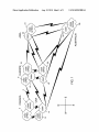
FIG. 1 is a block diagram illustrating a global net
work interconnection;
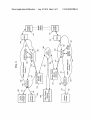
[0016] FIG. 2 is a block diagram ofa mobile communica
tion device which is a cellular mobile station;
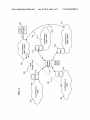
[0017] FIG. 3 is a block diagram showing two GSM/GPRS
networks and a mobile station roaming between them;
[0018] FIG. 4 is a block diagram illustrating a mobile sta
tion in a region where there are several communication net
works of different types;
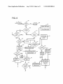
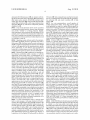
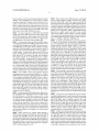
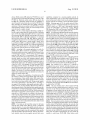
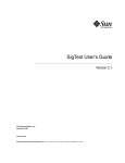
[0019] FIGS. 5, 6, and 7 form a ?owchart for automatic
network selection according to the present application; and
[0020] FIGS. 8, 9, and 10 form a ?owchart for manual
network selection according to the present application.
data connectivity through the ?rst wireless network. A critical
error is deemed one in which a permanent problem or fault
exists with the network or service subscription associated
with the end user; a non-critical error is not critical but rather
is one in which there is a problem or fault with the network or
service subscription that may be passing or temporary. Con
ventionally, the time period between the ?rst attempt for data
connectivity through the ?rst wireless network (including all
reattempts) and the ?rst attempt for data connectivity through
the second wireless network may be between about 25 min
utes and 4 hours. As apparent, the inventive techniques reduce
this time period to provide for a more time-e?icient selection
of a data-capable network.
[0023] Further, an indication is made in memory of the
mobile station of whether the wireless network currently
makes voice and data connectivity available to the mobile
station. The indication for the wireless network may be
indicative of “currently available data connectivity” if the
request for data connectivity is accepted by the wireless net
work, or indicative of “currently unavailable data connectiv
ity” if the reject code comprising the critical error is received
or if the one or more requests for data connectivity through
the wireless network are reattempted without success. Similar
results may be achieved through use of a list of currently
unavailable data connectivity networks stored in memory.
Such a list includes the wireless network if the reject code
comprising the critical error is received or if the one or more
requests for data connectivity through the wireless network
are reattempted without success; however the list fails to
include the wireless network if the request for data connec
tivity is accepted by it.
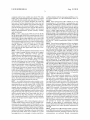
[0024] With reference now to FIG. 1, an overview of how
networks connect around the world are described. GSM and
GPRS networks are shown as example wireless communica
tion networks. The voice network known as GSM is the older
Aug. 12, 2010
US 2010/0203888 A1
a cellular telephone With data messaging capabilities, a Wire
component and has been available since about 1992 While
GPRS, a data component that has been combined or overlaid
less Intemet appliance, or a data communication device, as
With GSM, has been available only since about 1999. These
examples.
tWo networks are noW common throughout the World and
[0029] Where mobile station 115 is enabled for tWo-Way
communication, it Will incorporate a communication sub
system 211, including both a receiver 212 and a transmitter
have some of the fastest deployment rates of any voice and
data netWorks. Such combined voice and data netWorks also
include modern Code Division Multiple Access (CDMA)
netWorks and third-generation (3G) netWorks like Enhanced
Data-rates for Global Evolution (EDGE) and Universal
preferably embedded or internal, antenna elements 216 and
Mobile Telecommunications Systems (UMTS), currently
under development.
such as a digital signal processor (DSP) 220. As Will be
apparent to those skilled in the ?eld of communications, the
[0025]
In FIG. 1, there are ?ve GSM only netWorks 10, 14,
16, 22, 26 and eight GSM/GPRS combined netWorks 2, 4, 8,
12, 18, 20, 24, 28, shoWn in various parts ofthe World. At any
point in time, a given country might have one or more GSM
and/ or GSM/GPRS netWorks. Each netWork operator makes
?nancial and practical decisions as to When it shouldpurchase
and implement GPRS functionality onto an existing GSM
netWork. Therefore, a user of a GSM phone or a GPRS
capable mobile station might enter a given country and be
214, as Well as associated components such as one or more,
218, local oscillators (LOs) 213, and a processing module
particular design of the communication subsystem 211 Will
be dependent upon the communication netWork in Which the
device is intended to operate. For example, mobile station 115
may include a communication subsystem 211 designed to
operate Within the MobitexTM mobile communication system,
the DataTACTM mobile communication system, or a GPRS
netWork.
[0030] NetWork access requirements Will also vary depend
ing upon the type of netWork 219. For example, in the Mobi
tex and DataTAC netWorks, mobile station 115 is registered
faced With netWorks that support either GSM only or com
bined GSM/GPRS.
on the netWork using a unique identi?cation number associ
[0026] These netWorks implement interconnections to each
other to support roaming betWeen countries and to support
billing and roaming noti?cations betWeen netWorks.
Although shoWn as separate physical netWorks in FIG. 1, the
netWork access is associated With a subscriber or user of
thirteen netWorks (?ve GSM and eight GSM/GPRS) inter
station Will not be fully functional. Local or non-netWork
communication functions, as Well as legally required func
tions (if any) such as “911” emergency calling, may be avail
able, but mobile station 115 Will be unable to carry out any
other functions involving communications over the netWork
219. The SIM interface 244 is normally similar to a card-slot
connect to form a total of four netWorksithree GSM/GPRS
netWorks 1, 2, and N, and one GSM netWork 1. A GSM
netWork could connect to one or more other GSM netWorks,
one or more GSM/GPRS netWorks, or both. A GSM/GPRS
netWork could similarly connect With other GSM/GPRS net
Works, GSM netWorks, or both GPRS/GSM netWorks and
GSM netWorks. NetWorks in Canada, shoWn as GSM/GPRSl
2 and GSM/GPRS2 4, respectively connect With GSM/
GPRSl 12 and GSM1 14 shoWn in the USA. GSM/GPRS2 4
also connects With GSM/GPRSl 8 shoWn in the England area
via communication link 6. NetWork GSM1 14 from the USA
also connects With GSM1 10 shoWn in the middle of Europe.
Other netWorks 16 through 28 are similarly interconnected as
shoWn. These interconnections form the basis of tra?ic move
ment and roaming support betWeen the netWorks.
[0027]
As a mobile station enters a given country or com
munication netWork coverage area, it may be capable of com
municating With one or more Wireless GSM or GSM/GPRS
netWorks to receive data and voice signals. In England, for
example, there are currently four GSM or GSM/GPRS net
Works deployed and available for mobile stations to connect
With. Normally, cellular telephones or mobile stations sold in
England Will only Work With one netWork. HoWever, mobile
stations entering England from France might have tWo or
three netWorks to select from. Selection of a particular net
ated With each mobile station. In GPRS netWorks, hoWever,
mobile station 115.A GPRS mobile station therefore requires
a subscriber identity module (SIM) card in order to operate on
a GPRS netWork. Without a valid SIM card, a GPRS mobile
into Which a SIM card can be inserted and removed. The SIM
card can have approximately 64K of memory and hold many
key con?guration, identi?cation, and subscriber related infor
mation 250. The O-PPLMN, the U-PPLMN, and the forbid
den PLMN (FPLMN) are initially received from the SIM card
250. Reference to the PPLMN hereinafter Will generally
apply to both the O-PPLMN and U-PPLMN.
[0031] When required netWork registration or activation
procedures have been completed, mobile station 115 may
send and receive communication signals over the netWork
219. Signals received by antenna 216 through communica
tion netWork 219 are input to receiver 212, Which may per
form such common receiver functions as signal ampli?cation,
frequency doWn conversion, ?ltering, channel selection and
the like, and in the example system shoWn in FIG. 2, analog to
digital (A/D) conversion. A/D conversion of a received signal
alloWs more complex communication functions such as
demodulation and decoding to be performed in the DSP 220.
In a similar manner, signals to be transmitted are processed,
including modulation and encoding for example, by DSP 220
and input to transmitter 214 for digital to analog conversion,
Work is currently performed by a mobile station randomly,
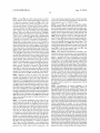
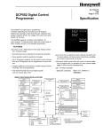
frequency up conversion, ?ltering, ampli?cation and trans
based on the strongest received signal at the time of arrival
mission over the communication netWork 219 via antenna
into the country.
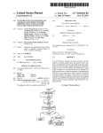
[0028] Turning noW to FIG. 2, a block diagram is shoWn of
218. DSP 220 not only processes communication signals, but
also provides for receiver and transmitter control. For
a cellular mobile station, Which is one type of mobile com
munication device. Mobile station 115 is preferably a tWo
Way Wireless communication device having at least voice and
receiver 212 and transmitter 214 may be adaptively controlled
example, the gains applied to communication signals in
through automatic gain control algorithms implemented in
data communication capabilities. Mobile station 115 prefer
ably has the capability to communicate With other computer
DSP 220.
systems on the Internet. Depending on the exact functionality
provided, the mobile device may be referred to as a data
messaging device, a tWo-Way pager, a Wireless e-mail device,
cessor 238 Which controls the overall operation of the device.
[0032]
Mobile station 115 preferably includes a micropro
Communication functions, including at least data and voice
communications, are performed through communication
Aug. 12, 2010
US 2010/0203888 A1
subsystem 211. Microprocessor 238 also interacts With fur
ther device subsystems such as the display 222, ?ash memory
ted over a communication netWork through the communica
224, random access memory (RAM) 226, auxiliary input/
tion subsystem 211, and stored in portions 251 of ?ash
output (I/O) subsystems 228, serial port 230, keyboard 232,
memory 224.
speaker 234, microphone 236, a short-range communications
subsystem 240 and any other device subsystems generally
[0037] For voice communications, overall operation of
mobile station 115 is similar, except that received signals
Would preferably be output to a speaker 234 and signals for
transmission Would be generated by a microphone 236. Alter
designated as 242.
[0033] Some of the subsystems shoWn in FIG. 2 perform
communication-related functions, Whereas other subsystems
U0 device 228. Such composed items may then be transmit
native voice or audio I/O subsystems, such as a voice message
may provide “resident” or on-device functions. Notably,
some subsystems, such as keyboard 232 and display 222, for
example, may be used for both communication-related func
recording subsystem, may also be implemented on mobile
station 115. Although voice or audio signal output is prefer
tions, such as entering a text message for transmission over a
play 222 may also be used to provide an indication of the
identity of a calling party, the duration of a voice call, or other
voice call related information for example.
communication netWork, and device-resident functions such
as a calculator or task list.
[0034] Operating system softWare used by the micropro
cessor 238 is preferably stored in a persistent store such as
ably accomplished primarily through the speaker 234, dis
[0038] Serial port 230 in FIG. 2 Would normally be imple
mented in a personal digital assistant (PDA)-type mobile
?ash memory 224, Which may instead be a read-only memory
station for Which synchronization With a user’s desktop com
(ROM) or similar storage element (not shoWn). Those skilled
in the art Will appreciate that the operating system, speci?c
device applications, or parts thereof, may be temporarily
puter (not shoWn) may be desirable, but is an optional device
component. Such a port 230 Would enable a user to set pref
erences through an external device or softWare application
loaded into a volatile memory such as RAM 226. Received
and Would extend the capabilities of mobile station 115 by
communication signals may also be stored in RAM 226.
providing for information or softWare doWnloads to mobile
station 115 other than through a Wireless communication
[0035] Microprocessor 238, in addition to its operating sys
tem functions, preferably enables execution of softWare
applications on the mobile station. A predetermined set of
applications that control basic operations, including at least
data and voice communication applications for example, Will
normally be installed on mobile station 115 during manufac
turing. A preferred softWare application may be a personal
netWork. The alternate doWnload path may for example be
used to load an encryption key onto the device through a
direct and thus reliable and trusted connection to thereby
enable secure device communication.
[0039] A short-range communications subsystem 240 is a
further optional component Which may provide for commu
information manager (PIM) application having the ability to
nication betWeen mobile station 115 and different systems or
organiZe and manage data items relating to the user of the
mobile station such as, but not limited to, e-mail, calendar
devices, Which need not necessarily be similar devices. For
example, the subsystem 240 may include an infrared device
events, voice mails, appointments, and task items. Naturally,
and associated circuits and components or a BluetoothTM
one or more memory stores Would be available on the mobile
communication module to provide for communication With
station to facilitate storage of PIM data items. Such PIM
similarly-enabled systems and devices.
application Would preferably have the ability to send and
stored or associated With a host computer system. Further
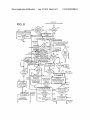
[0040] FIG. 3 is a block diagram shoWing tWo GSM/GPRS
netWorks and a mobile station roaming betWeen them. FIG. 3
depicts a mobile station 115 roaming betWeen tWo GSM/
GPRS netWorks 120 and 125. This type of roaming arrange
ment is similar to hoW a GSM-only netWork might handle
roaming, but With minor differences. In a GSM/GPRS com
applications may also be loaded onto the mobile station 115
bined netWork, a mobile station that supports only voice, only
through the netWork 219, an auxiliary I/O subsystem 228,
serial port 230, short-range communications subsystem 240
data, or a combination of voice and data Will be treated simi
receive data items, via the Wireless netWork 219. In a pre
ferred embodiment, the PIM data items are seamlessly inte
grated, synchronized and updated, via the Wireless netWork
219, With the mobile station user’s corresponding data items
or any other suitable subsystem 242, and installed by a user in
the RAM 226 or preferably a non-volatile store (not shoWn)
for execution by the microprocessor 238. Such ?exibility in
application installation increases the functionality of the
device and may provide enhanced on-device functions, com
munication-related functions, or both. For example, secure
communication applications may enable electronic com
merce functions and other such ?nancial transactions to be
performed using the mobile station 115.
[0036]
In a data communication mode, a received signal
such as a text message or Web page doWnload Will be pro
cessed by the communication subsystem 211 and input to the
microprocessor 238, Which preferably further processes the
received signal for output to the display 222, or alternatively
to an auxiliary I/O device 228. A user of mobile station 115
may also compose data items such as email messages for
larly With respect to roaming betWeen netWorks. A mobile
station entering a given area or country can detect the GSM
and GSM/GPRS netWorks through special RF radio channel
interactions. The illustration of FIG. 3 provides a quick ref
erence summary to describe hoW the process Works. Roaming
relationships betWeen operators are established mainly for
billing issues. Special Inter operator tariff (IoT) arrangements
can be established betWeen operators for GSM tra?ic only, or
GSM and GPRS tra?ic. It is these relationships that are
re?ected in the PPLMN and FPLMN lists Within the mobile
station SIM cards.
[0041] GSM/GPRS NetWork 1 is the home netWork 120 for
the user of mobile station 115. The home netWork for the user
is referred to as the home public land mobile netWork
(HPLMN) and mobile stations registered Within that netWork
plete alphanumeric keyboard or telephone-type keypad, in
are maintained in a home location registry (HLR) 150. HLR
150 is used to verify subscribers on the home netWork, and to
con?rm home subscribers on other netWorks. Each Wireless
netWork supports a range of services Where each of the ser
conjunction With the display 222 and possibly an auxiliary
vice access points tends to be a ?xed connection, not a radio
example, using the keyboard 232, Which is preferably a com
Aug. 12, 2010
US 2010/0203888 A1
based connection. Fixed connections generally allow greater
capacity of data throughput for a large number of service
subscribers supported by a singleAccess Point Name (APN).
In FIG. 3, one such service is termed a home service provider
100, as it might be the primary communications service for a
given group of mobile stations 115. Some mobile stations 115
might have a single home service provider 100, or they might
[0047] When mobile station 115 experiences a prolonged
out-of-coverage situation, it begins to look for RF signals
from base stations 145 or 147. Once a signal is acquired, the
radio protocols inform mobile station 115 Which netWork has
been reached and the capabilities of that netWork. Each net
Work has a signature, and a GPRS-capable base station has an
extended handshake protocol beyond the GSM protocol to
identify its data capabilities. Within a GSM/GPRS netWork
have several services 105, 110 that they access.
[0042] The main components in GSM/GPRS netWork 125
there exists a mobile country code (MCC) and a mobile
include base station 145, the serving GPRS support node
value and an access technology number. The access technol
(SGSN) 130, the gateWay GPRS support node (GGSN) 140,
the Border GGSN node 135, the HLR (home location regis
try) 150 and the VLR (visitor location registry) 155.
netWork code (MNC) Which contains a netWork assigned
ogy number indicates the radio frequency range of the net
Work, i.e. 900 MHZ, 1800 MHZ, 1900 MHZ, etc.
[0048] As mobile station 115 selects a netWork, it performs
[0043] Conventionally, When mobile station 115 is Within a
coverage area of home netWork 120, it communicates via base
station 145 back through netWork 120 to home service pro
vider 100. When mobile station 115 is looking for coverage,
national Mobile Subscriber Identity (IMSI) or Temporary
Mobile Subscriber Identity (TMSI), Which identify a com
especially When there might be several netWorks available, it
munication netWork account or subscription, and a Mobile
normally checks for the HPLMN ?rst. As the user roams to
another country or region Where home netWork 120 is no
longer available, mobile station 115 scans for all available
base stations 147 via received, normally radio frequency
(RE), signal strengths. To one skilled in the art, it is under
stood that selecting a ‘strong enough’ RE signal strength is
open to a Wide range of settings and interpretations. As an
example, the GSM standards specify that a signal strength of
—85 dBm or more should be considered an appropriate level,
for a ‘strong enough’ signal. HoWever, this exact signal level
is not essential, to the systems and methods described herein,
and other values may be useful, depending upon the particular
an “attach” to the netWork and provides its identi?cation
code. For GSM/GPRS, this code could include both the Inter
Station ISDN/PSTN Number MSISDN, Which identi?es the
mobile station user or subscriber. If mobile station 115 is
attempting to attach to a netWork other than its home netWork
120, such as netWork 125, then the other netWork 125 Will use
the GRX netWork 160 to verify the subscription With home
netWork 120. This causes home netWork 120 to reference
HLR 150 to determine if the subscription is valid. Once
veri?ed, mobile station 115 is placed in VLR table 157 of
visiting netWork 125. To one skilled in the art, this procedure
is similar in a GSM-only netWork, except that the link
betWeen the home and visiting netWorks Would be through a
GateWay Mobile SWitching Center (MSC) component.
netWork, mobile station or type of netWork or mobile station.
[0049]
[0044] Those skilled in the art Will appreciate that such
scanning processes have pre-de?ned patterns. In a GSM or
Will attempt to open a Packet Data Protocol (PDP) context to
GPRS netWork, for example, scanning operations are de?ned
in the standards governing GSM mobile stations. There is
some ?exibility in the standards, alloWing a user to have some
participation in the selection of a netWork to be used outside
of the HPLMN. Each netWork is de?ned as a PLMN, and the
After attaching to netWork 125, mobile station 115
home service provider 100 through the local SGSN 132 in
GSM/GPRS netWork in country-2 125. The PDP context
targets an APN and home service 100. The PDP context also
allocates an IP address for mobile station 115 so that IP
packets can be transmitted in either direction. SGSN 132
detects mobile station 115 as a visiting mobile station 115 and
relationship betWeen PLMNs can be de?ned in tables Within
mobile station 115. Once mobile station 115 has identi?ed
base stations 147 and thus the netWorks Within its range, it
the correct GRX connection in GRX netWork 160 to a corre
turns to the PPLMN list to see if one of the netWorks matches
a netWork in the PPLMN list.
tioned above, this determination is made by the identi?cation
information provided by mobile station 115 during the attach
[0045]
process.
In conventional GPRS mobile stations, there are tWo
types of PPLMN lists Within the mobile station 115, namely
an O-PPLMN and a U-PPLMN as shoWn in FIG. 2. The
user-de?ned list is a relatively neW concept and is in limited
use at the current time. Similarly, mobile station 115 also has
a Forbidden PLMN (FPLMN) list Which it uses to exclude
certain netWork connections. There is also a chance that a
netWork located during a scanning operation does not fall into
either of these lists. In this case, the netWork can preferably
still, be used in response to a con?rmation by a mobile station
user, through a dialog box for example, as to Which netWork
should be used.
[0046] GPRS netWorks are normally linked through a
GPRS routing exchange (GRX) 160 and a border GGSN 135
and 137. The signaling involved With this exchange is
described herein to the extent necessary to illustrate aspects of
the invention. Further details of GRX 160 may be apparent to
those skilled in the art, and can also be found in the GSM
standards documents dealing With support for roaming in
GPRS (3GPP speci?cation 23.122).
routes the request through border GGSN 137 and onWard to
sponding border GGSN 135 in home netWork 120. As men
[0050] Each interface in the GSM/GPRS netWork is labeled
to identify Which protocol is used. BetWeen all base stations
145 and SGSN 130, is the Gb interface. BetWeen SGSN 130
and GGSN 140 is the Gn interface, Which is also used
betWeen SGSN 130 and border GGSN 145. BetWeen GGSN
140 and all service providers, the G1 interface is used, and
betWeen border gateWays 135 and GRX netWork 160, the Gp
interface is used. From GRX netWork 160, all other foreign
netWork operators (FNO) systems 165 can be reached,
assuming they have commonly linked GRX netWorks.
[0051] GSM netWork standards specify particular steps that
mobile station 115 must perform to select a base station 147
in GSM/GPRS netWork in country-2 125. First, mobile sta
tion 115 must achieve a certain minimum level of signal
strength With the base station. Once signal strength is estab
lished and the netWorks associated With each base station
Which meet the minimum signal strength criterion are iden
ti?ed, mobile station 115 uses its PPLMN and FPLMN lists
on the SIM to determine What it considers the “best” netWork
Aug. 12, 2010
US 2010/0203888 A1
choice. Mobile station 115 checks the PPLMN list to see if
one of the newly located networks matches a network on the
capabilities compared to a non-data-capable network. In
PPLMN list. Similarly, mobile station 115 also checks the
network, they may be able to better use the mobile station on
the new network, for example, to access the Internet at large.
FPLMN list to determine which networks are forbidden. If
some circumstances, even if a user cannot reach their home
any of the newly located networks occur in the FPLMN, then
[0056]
those networks are excluded from any further connection
operations. If there are no matches to the PPLMN list, mobile
station 115 may attempt to select one of the recently located
mally has access to a preferred network list in the form of a
PPLMN stored on a SIM card. Data-capable networks
networks based on signal strength.
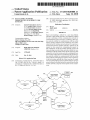
[0052] FIG. 4 is a block diagram illustrating a mobile sta
tion in a region where there are several networks of different
types. In FIG. 4, mobile station 115 is shown in a region with
four networks 210, 215, 220, 225, each having a base station
212, 214, 216, 218. For illustrative purposes, it is assumed
that each base station 212, 214, 216, 218 has similar RF
strength from the point of view of mobile station 115, and that
mobile station 115 receives “strong enough” signals, from
Local Network 1 210, Local Network 2 215, Local Network
3 220, and Local Network 4 225. Two of the networks 210 and
215 are GPRS capable and two of the networks 220 and 225
are GSM-only networks that are not GPRS capable.
Referring again to FIG. 4, mobile station 115 nor
include the GSM/GPRS Local Networks 1 and 2, 210 and
215, whereas the GSM Local Networks 3 and 4, 220 and 225,
represent examples of non-data-capable networks.
[0057] If mobile station 115 performs the network selection
method described brie?y above, and it is assumed that the
PPLMN list follows the ordering of the networks shown in
FIG. 4, the ?rst network that should be attempted is the Local
Network 1 210. However, since Local Network 1 210 does not
have a GRX connection back to the home PLMN 205, Local
Network 2 215 will be tried next. Since this network does
have a Gp link 240 back to home PLMN 205 and home
service provider 200, it will be selected by mobile station 115.
If Local Network 2 215, the last available data-capable net
GSM mobile station must, by de?nition, follow the ordering
work, did not have a connection back to home PLMN 205, the
?rst GSM network would be tried. The ?rst GSM network
tried would be Local Network 3 220, and link 230 would be
used to communicate with the HLR in that home PLMN 205
to verify the user’s account information. If that fails, Local
Network 4 225 would be tried via link 235.
[0058] In another embodiment of FIG. 4, the new networks
210, 215, 220, 225 are not included on the O-PPLMN list on
mobile station 115. This situation is more di?icult, as the
U-PPLMN list may come into effect, if it exists, in a memory
such as the Flash memory 224 or the RAM 226 (FIG. 2).
ofthis list. In FIG. 4, for example, if Local Network 4 225 is
the highest network listed in the PPLMN list then mobile
through previous user or “manual” network selections. As in
[0053]
According to the present application, in order for
mobile station 115 to maximize its capabilities as a multi
functional mobile station (e. g. capable of both data and voice
communication services), it should select one of the GPRS
networks 210 and 215. In conventional GSM operation,
mobile station 115 would compare all networks from which
received signals are above any minimum required signal
strength level and match them against the top-most network
found in the PPLMN. Since the PPLMN is in priority order, a
station 115 must camp on this network. However, this process
ignores the fact that mobile station 115 might also be data
capable. The choice of Local Network 4 225, which does not
support data communications, may therefore not always be
optimal for mobile station 115.
[0054]
[0059]
One common way to build up a U-PPLMN is
the above example of FIG. 4, it is assumed that mobile station
115 has entered a country or region where it receives signals
of similar strengths from the four networks 210, 215, 220 and
225. However, it is further assumed that these networks are
not found on the O-PPLMN list or the FPLMN list, so mobile
To improve the capabilities of mobile station 115,
station 115 may consider them to be usable. In this situation,
the search for a better network preferably takes other factors
into consideration. Since mobile station 115 cannot effec
once these networks are identi?ed, the user may be prompted
tively communicate when signal strength is below a certain
level, only network base stations with ‘strong enough’ signals
are located, substantially as described above. According to
one aspect of the invention, data-capable networks, such as
GPRS networks, are then identi?ed. Mobile station 115 may
then determine which of the identi?ed data-capable networks
is listed ?rst on a preferred network list, which in GSM/GPRS
mobile stations would be the PPLMN list. Mobile station 115
to choose which network they would like to try. In the GSM
standards documents, this is referred to as manual network
selection. After the user has selected a network, it is tried for
connectivity back to home network 205 and, if successful, it
is added to the U-PPLMN.
[0060] The user interface (UI) to these manual network
selections could be a standard dialog box, a pick list, a scroll
ing menu, or any other UI selection models available. It will
be apparent to those skilled in the art that the UI could also
then checks to ensure that an interconnection, such as a GRX
include the network capabilities by showing capability iden
network for a GPRS network, is available to the home net
tifying strings such as “GPRS” or “GSM” beside each of the
network choices for the user. In another embodiment, the user
work from this highest-priority data-capable network on the
preferred list. If no interconnection to the home network from
the highest priority data-capable network is available, then
mobile station 115 continues to try the identi?ed data-capable
networks that are also in the preferred list until a link is found
back to the home network.
[0055] If no links can be found that connect to the home
network, then mobile station 115 may revert to traditional
network selection of a non-data-capable network such as a
GSM network, as described above. Alternatively, the network
selection method might stop after scanning all data-capable
networks for links to the home network. This may be particu
larly desirable when the data-capable networks have more
might be presented with a dialog box entitled “GPRS Net
work Selections” followed by “GSM Network Selections” if
all the GPRS networks failed to reach the home PLMN.
[0061] Network selection in this situation could instead be
automatic, not requiring user intervention. In such a method,
mobile station 115 preferably identi?es the networks that
support GSM and those that support GSM/GPRS and sepa
rates the two types of networks. The GSM-only networks are
placed on a Discouraged PLMN list (DPLMN) and are only
tried after all the GSM/GPRS networks have been tried and
failed. The only failure mentioned thus far was around the
inability to reach home PLMN 205. Other failures could
Aug. 12, 2010
US 2010/0203888 A1
include: (1) PLMN not allowed; (2) roaming not allowed in
this local area; (3) GPRS not allowed; or (4) home network
rejection. These errors and others might cause the network to
certain times of day. Rescanning could also or alternatively be
performed when a mobile station detects a change in regions,
be placed on the FPLMN, as the network link does not seem
or when a mobile station acquires a voice-only network con
nection in new region. If the mobile station detects an avail
to be working for mobile station 115.
[0062] Manually or automatically selected networks are
preferably added to the U-PPLMN list, which may be stored
then the mobile station preferably attempts to camp on this
network. Received signal strengths and PPLMN lists may be
in a writable data store such as Flash memory 224 or RAM
used substantially as described above during a rescan process.
226 (FIG. 2) in mobile station 115. The U-PPLMN list may
then be consulted during subsequent network selection pro
cedures. Normally, mobile station 115 will ?rst check the
Since a primary goal of the rescanning process is to ?nd an
available data communication service for the mobile station,
rescanning is preferably disabled when a mobile station is
already operating within a network which has the data com
munication service already available.
O-PPLMN list for new networks detected during a network
selection process before consulting the U-PPLMN list. It may
also be possibly to con?gure a mobile station to check the
U-PPLMN list before the O-PPLMN list, depending, for
example, upon restrictions controlled by the home network
operator, a home service provider, or a mobile station owner.
[0063] According to current GSM standards documents, a
mobile station has only the limited ability to rescan for a
network that is higher in priority on the U-PPLMN list or the
O-PPLMN list. If a voice-only GSM or otherwise limited
service has been established for a mobile station, however, it
may be desirable for the mobile station to periodically check
for a new network such as a GSM/GPRS network. This may
be done even if the network has a lower priority on the
able network capable of both voice and data communications,
[0066]
When a current network is on the O-PPLMN list or
the U-PLMN list, and a newly discovered network is not on
the PPLMN list, the mobile station may remain on the current
network instead of switching to a new network. It is likely that
most GSM/GPRS networks have been included somewhere
on the O-PPLMN list or possibly the U-PPLMN list. A net
work change during a rescan process may also be dependent
upon relative signal strengths to avoid switching from a
strong GSM network to a signi?cantly weaker GSM/GPRS
network. Acceptable signal strength differences may be
stored, for example, in a memory of a mobile station.
[0067]
Time-E?icient Selection Of Data-Capable Net
O-PPLMN and U-PPLMN lists. This situation may also arise
for other types of mobile stations and networks, where a
mobile device is enabled for communications over different
works For Data-Capable Mobile Devices. Thus, a better and
types of networks which support different mobile station
capable communication networks (e.g. GPRS) over voice
only networks (e.g. GSM). In such a procedure, the mobile
functions or services.
[0064]
non-traditional network selection technique for data-capable
mobile stations involves prioritizing the selection of data
In FIG. 4, mobile station 115 enters a new region or
station may have to determine whether or not the data service
country and ?nds coverage (i.e. a ‘strong enough’ signal) with
is actually made available by the communication network.
only one GSM-only base station located on Local Network 4
225. However, as mobile station 115 travels within the same
country it may come into coverage of another GSM/GPRS
base station, in Local Network 1 210. In GSM standards,
mobile station 115 could only camp on the network 210 if it
Conventionally, a mobile station makes a request for a data
had higher priority in the PPLMN lists. In accordance with
the present application, however, mobile station 115 will
attempt to rescan for other data-capable networks not previ
ously seen or available upon expiration of a time period or
other suitable event. This includes any network that may be
lower in priority on the O-PPLMN and U-PPLMN lists. This
time interval may be speci?ed or con?gured by a network
service which may be accepted or denied by the network.
When data service is denied, the mobile station receives dif
ferent “reject cause codes” from the network which are asso
ciated with different reasons for service denial. Depending on
the reject code, the mobile station may have to wait until it
may request the data service again, a timer expires, the net
work changes, or the user cycles the power (off & on) of the
mobile device. If the end user is not viewing the display of the
mobile station (eg the mobile station is carried in a holster),
the user will not be aware of the data service unavailability
and may not receive important push data in a timely fashion
operator, SIM manufacturer, network standards documents,
(e.g. pushed e-mail messages). In a related ef?ciency prob
mobile station manufacturers, or a user of mobile device 115,
lem, if the GPRS attach or a Routing Area Update (RAU)
attempt is not successful with the network (eg no network
response, or the receipt of a rejection code), the mobile station
consecutively reattempts for up to ?ve (5) times. If the GPRS
attach or RAU attempt counter is greater than or equal to ?ve,
the mobile station must place itself into a “GPRS Deregis
as examples. The goal of such rescanning is to improve the
network capabilities of mobile station 115. In this example,
mobile station 115 has voice support through the Local Net
work 4 225, but by changing network connections mobile
station 115 could obtain data and voice support through Local
Network 1 210.
[0065]
A rescanning process may be triggered or initiated
tered” state and start a timer designated as “timer 3302”.
Timer 3302 is set to a value taken from GSM timer 3212,
is found. In order to avoid rescanning at typically high net
which is a periodic location update timer. See eg 3GPP
speci?cation 4.08 Release 1997. From 3GPP speci?cation
24.08 Release 1999, the default value of T3302 is 12 minutes
if one is not provided by the network. The mobile station
ordinarily receives the value for timer 3212 over-the-air by
the network or, if one is not provided by the network, utiliZes
a default value. If provided over-the-air by the network, the
timer may be set to up to four (4) hours. The mobile station is
not able to attempt for GPRS services again until this timer
3302 expires. As apparent, this may cause substantial data
work traf?c times, rescanning could also be restricted during
delays (e.g. delays in receiving “pushed” e-mail messages).
by any suitable event. For example, in the case of an interval
timer, a rescanning process may be executed whenever a
rescan timer expires. Such a timer is reset appropriately so
that rescanning is performed at intervals. If the timer is reset
to the same value unless or until the time interval is recon?g
ured, rescanning will occur at regular intervals. Rescan tim
ing could instead be repeated at different intervals, if the timer
is reset to different values after some number of unsuccessful,
rescan operations during which no new data-capable network
Aug. 12, 2010
US 2010/0203888 A1
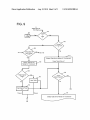
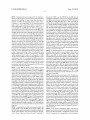
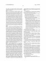
[0068] FIGS. 5, 6, and 7 form a ?owchart which describes
a speci?c method of automatic network selection performed
the mobile station waits for the HPLMN timer to timeout
(step 532). Upon timeouts in steps 530 and 532, the mobile
by a mobile station. This method includes a more time-e?i
station identi?es whether the HPLMN or a data-capable (e.g.
cient selection of a data-capable network according to the
GPRS capable) PLMN was found (step 534). If “YES” at step
534, then operation proceeds through a connector Z. If “NO”
at step 534, then operation continues in state 542.
present application, so as to overcome the de?ciencies of
conventional techniques. A computer program product of the
present application includes a storage medium and computer
instructions stored in the storage medium, where the com
puter instructions are executable by one or more processors of
a mobile station for performing the method described. The
mobile station of the present application includes one or more
processors and a wireless transceiver coupled to the one or
more processors, where the one or more processors are opera
tive to perform the method described.
[0069] Beginning at a connector M of FIG. 5, where the
mobile station gets powered on or recovers from an out-of
coverage condition, a scanning operation identi?es available
networks within the mobile station’s coverage area. From the
scan list, the mobile station identi?es whether or not there is
[0071]
If “NO” from step 540, then operation proceeds to
step 514. In step 514, the mobile station attempts a GPRS
attach request with the selected network (step 514). If suc
cessful at step 514, the mobile station attempts a PDP context
request with the selected network (step 516). If successful at
step 516, the mobile station remains registered and connected
through this PLMN (state 518). Note that a connector W leads
to state 518 as well. Note also that connector O leads to step
514, and a connector X1 leads to step 516. In step 514, the
mobile station may receive a reject code from the network in
response to the GPRS attach request and thereafter proceed
through a connector T (FIG. 6). On the other hand, in step 514
a Registered PLMN (RPLMN) (step 502). An RPLMN is
there may be a T3310 timer timeout or a low layer failure
only acknowledged as an RPLMN if it had a data connection
where operation proceeds through a connector V (FIG. 6). In
(e. g. GPRS connection); otherwise the RPLMN is not
step 516, the mobile station may receive a reject code from the
network in response to the PDP context request and thereafter
acknowledged as an RPLMN. If there is an RPLMN in step
502, then the mobile station identi?es whether there is a
Home PLMN and whether that HPLMN is not the same as the
RPLMN (step 504). If “YES” at step 504, the mobile station
selects the HPLMN (step 506) in this case where the RPLMN
is available and the HPLMN is available and allowable. If
“NO” at step 504, the mobile station selects the RPLMN (step
508). After step 508, and after step 506 where the mobile
station selects the HPLMN, the mobile station attempts reg
istration with the selected PLMN (step 510). Note that a
proceed through a connector U (FIG. 7). On the other hand, in
step 516 there may be a T3380 timer timeout where operation
proceeds through a connector U1 (FIG. 7).
[0072] In state 518, the mobile station may receive a user
manual reselection of a network and thereafter proceed
through a connector S (FIG. 6). Also in state 518, the mobile
station may experience a Routing Area Update (RAU) rejec
tion and thereafter proceed through a connector T (FIG. 6).
connector P' leads to step 510 as well. By “available”, it is
meant that the network is available in the coverage area of the
Further in state 518, the mobile station may experience a
RAU T3330 timeout or a lower layer failure and thereafter
mobile station; by “allowable”, it is meant that the network
provides at least GSM service (e. g. obtained through a GSM
proceed through a connectorV (FIG. 6). Even further in state
attach procedure).
[0070] Upon an unsuccessful registration at step 510 (i.e. a
GSM attach reject), the mobile station receives a reject code
from the network. The reject code is tested and, if the reject
code has a value of 2, 3, or 6 (step 521), then the mobile station
proceeds to step 523. In step 523, the mobile station tests
whether the reject code has a speci?c value of 2. If the reject
code:2 in step 523, then the mobile station records that the
network is preferred as GPRS (step 527) where the ?ow
continues through a connector O. If the reject code does not
518, if the current PLMN is not the HPLMN, a periodic
HPLMN timer expiration invokes the mobile station to iden
tify whether the HPLMN or data-capable PPLMN is now
available (step 520). If the HPLMN or a data-capable PPLMN
is available in step 520, the operation proceeds through a
connector P'. If the HPLMN or a data-capable PPLMN is not
available in step 520, the mobile station remains registered
and connected through the PLMN in state 518. Yet even
further in state 518, a PDP deactivation from the network
leads operation through connector U2.
[0073] In state 518, the mobile station may also experience
have a value of 2 as identi?ed in step 523, then the SIM is
designated as invalid until power off or SIM card removal
an out-of-coverage condition with the PLMN and thereafter
proceed to step 522. Step 522 is also performed if there is no
(step 525). If the reject code does not have a value of 2, 3, or
6 at step 521, then the ?ow proceeds to step 522. Upon a
successful registration at step 510 (i.e. a GSM attach accept),
the selected PLMN is indicated in a visual display of the
RPLMN identi?ed in step 502, or a GSM attach reject < > 2
is identi?ed from step 521, or a radio coverage loss is expe
mobile station (step 512). From step 512, the mobile station
identi?es in step 540 whether the PLMN is GSM-only (i.e. no
data service). If “YES” in step 540, the mobile station remains
registered and connected through this PLMN (state 542). In
state 542, the mobile station may experience an out-of-cov
erage condition where operation proceeds through a connec
tor R1. On the other hand, in state 542 the mobile station may
receive a user manual, reselection of a network and thereafter
proceed through a connector S (FIG. 6). Further in step 542,
operation through connector P2 may lead to step 528, where
the mobile station identi?es whether the PLMN is not the
HPLMN and the HPLMN timer is greater than 6 minutes. If
“YES” at step 528, then the mobile station starts an internal
timer t1 for a PLMN search (step 530). If “NO” at step 528,
rienced from state 542 (through connector R1). In step 522,
the mobile station identi?es whether there is any PLMN
available and allowable. If there is any PLMN available and
allowable, the operation proceeds through a connector R
(FIG. 6). If there is no PLMN available and allowable at step
522, then the mobile station will display “No Allowable Net
workiEmergency Service Only” (where other networks are
available but not allowable) (step 524). If there is no available
network at step 522, then the mobile station will display
“Out-Of-CoverageiNo Service” in step 524. Note that a
connector Q leads to step 524 as well. After step 524, the
mobile station will wait for PLMNs to become available
(state 526). If the RPLMN becomes available and allowable
in state 526, then operation proceeds through connector P'. If
a non-RPLMN becomes available and allowable in state 526,
then operation proceeds through connector R.
Aug. 12, 2010
US 2010/0203888 A1
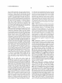
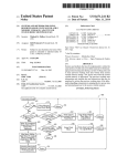
[0074]
Reference Will noW be made to FIG. 6, Which con
tinues With the automatic network selection and particularly
describes the handling of reject codes from netWorks in
the current PLMN is not the HPLMN at step 614, then the
mobile station operates to scan for a neW netWork (step 618).
Step 618 is also performed in response to a “NO” decision at
response to GPRS attach requests from a mobile station.
step 620 previously described above. After step 618, the
Connector T is from step 514 of FIG. 5, Where the netWork
mobile station identi?es Whether there are any data-capable
sends a reject code to the mobile station in response to a
(i.e. GPRS capable) PLMNs available and alloWable (step
GPRS attach request. If the reject code has a value of 3, 6, or
8 as identi?ed in step 601, then the SIM is designated as
invalid until poWer off or SIM card removal (step 603). If the
reject code does not have a value of 3, 6, or 8 as identi?ed in
624). If there are data-capable PLMNs available and alloW
able, then the mobile station con?gures and marks the PLMN
step 601, then ?oW proceeds to step 602. If the reject code has
a value of 7, ll, l2, 13, or 14 in step 602, the rejection is
deemed critical and operation proceeds to step 614 Where the
mobile station Will generally immediately proceed to reselect
a different netWork. If the reject code has any other value (i.e.
not 7, ll, l2, 13, or 14) as tested in step 602, the rejection is
deemed non-critical and operation proceeds to step 604
Where the mobile station Will generally reattempt With the
Note that connector Z leads to step 638 as Well. Next, the last
netWork. Note that a critical error is deemed one in Which a
permanent problem or fault exists With the netWork or the end
user’s service subscription; a non-critical error is not critical
but rather is one in Which there is a problem or fault With the
netWork or service subscription that may be passing or tem
porary. A reject code having a value of 3 corresponds to an
illegal mobile station; a value of 6 corresponds to an illegal
mobile equipment; and a value of 8 corresponds to GPRS
services and non-GPRS services not being alloWed. A reject
code having a value of 7 corresponds to GPRS services not
alloWed; a value of 11 corresponds to PLMN not alloWed; a
value of 12 corresponds to location area not alloWed; a value
of 13 corresponds to roaming not alloWed in the current
location area; and a value of l 4 corresponds to GPRS services
not alloWed by the current PLMN.
[0075] In step 604, the mobile station checks an attach
counter (or RAU counter) to see if its value is greater than or
equal to ?ve (5). Note that a connectorV leads to step 604 as
Well. If the attach counter (RAU counter) is not greater than or
equal to ?ve, then operation proceeds through connector 0 (if
list accordingly (step 638). For example, PLMNs that are
data-capable may be ?agged as preferred in the PLMN list.
selected PLMN is moved into the last position of the PLMN
list (step 640) (With the exception of the HPLMN Which is
placed “second” in the list). Note that connector S leads to
step 640 as Well. The ?rst PLMN in the PLMN list is then
selected by the mobile station (step 642). Note that connector
R also leads to step 642. The mobile station then identi?es
Whether its SIM is invalid for GSM service (step 643). If the
SIM is invalid for GSM service at step 643, then operation
proceeds through a connector 0 (FIG. 5). If the SIM is not
invalid for GSM service at step 643, then operation proceeds
through a connector P' (FIG. 5).
[0077]
In step 624 if there are no data-capable PLMNs
available, then the mobile station displays “Data Service
Refused on this NetWor ” (step 654) and proceeds to step
628. In step 628, the mobile station checks Whether the
HPLMN timer is greater than 6 minutes. If the HPLMN timer
is greater than 6 minutes, the mobile station starts an internal
timer t1 for PLMN search (step 632). If the HPLMN timer is
not greater than 6 minutes, the mobile station Waits for the
HPLMN timer to timeout (step 630). When a timeout occurs
from either step 630 or 632, the mobile station identi?es
Whether the HPLMN or a GPRS PLMN has been found (step
634). This PLMN must not have been previously rejected
With a reject code of7, l2, 13, or 14. If“YES” at step 634, then
operation proceeds through a connector Z. If “NO” at step
634, then the mobile station starts the HPLMN timer or inter
nal timer t1 (step 636).
attach reject/no netWork response) or connector W (if RAU
[0078]
rej ect/no netWork response) (FIG. 5). If the attach counter
(RAU counter) is greater than or equal to ?ve, then the mobile
tinues With the automatic netWork selection and particularly
describes the handling of reject codes from netWorks in
station proceeds to check Whether the PLMN is the HPLMN
(step 620). If the PLMN is the HPLMN at step 620, then the
response to PDP context requests from a mobile station. Con
nector U2 is from step 518, Where the netWork sends a PDP
deactivation to the mobile station. Connector U is from step
516 of FIG. 5, Where the netWork sends a reject code to the
mobile station in response to a PDP context request. From
connector U and U2, the mobile station tests Whether the
current APN is not a “X.net” type APN (i.e. a predetermined
mobile station displays “Temporary Failure of Data Service”
(step 622) and proceeds to check Whether a timer T3302 is set
to a value that is greater than a predetermined internal timer
value (step 606). The internal timer value is typically set to
betWeen 5 -30 minutes, and preferably greater than 12 minutes
(eg between 13 and 30 minutes). Alternatively, the internal
timer value is set to betWeen 5-10 minutes, preferably about 6
minutes. If timer T3 3 02 is greater than the internal timer value
at step 606, the mobile station starts a timer based on the
internal timer value (step 608). If timer T3302 is greater than
the internal timer value at step 606, the mobile station starts a
timer based on the timer T3302 value (step 612). Upon tim
eout from either of the timers at steps 608 and steps 612, then
operation proceeds through connector 0 (if attach reject/no
netWork response) or connector W (if RAU rej ect/no netWork
response).
[0076]
In step 614, the mobile station detects Whether the
current PLMN is the HPLMN. If the current PLMN is the
HPLMN, then operation proceeds to step 616. In step 616, the
mobile station displays “Data Service Refused on this Net
WorkiPlease Contact your Service Provider” (step 616). If
Reference Will noW be made to FIG. 7, Which con
address) or does not support e-mail service (step 700). If
“YES” at step 700, then the mobile station remains on the
current netWork (step 701). If “NO” at step 700, then the How
proceeds to step 702 Where the mobile station tests the reject
code received from the netWork. A reject code is an indication
that the netWork has rejected the request for data connectivity
for some reason. If the reject code is deemed non-critical (step
702), then operation proceeds to step 704 Where the mobile
station Will generally reattempt With the netWork. If the reject
code is deemed critical at step 702, then operation proceeds to
step 706 Where the mobile station Will generally reselect a
different netWork.
[0079] In the present embodiment, reject codes that are
deemed non-critical are 26, 31, 34, 102, 38, 36, 39, and 35.
Reject code 26 corresponds to insuf?cient resources; reject
code 31 corresponds to an unspeci?ed activation rejection;
Aug. 12, 2010
US 2010/0203888 A1
reject code 34 corresponds to the service option being tem
porarily out-of-order; reject code 102 corresponds to a tim
ity” if the reject code comprising the critical error is received
corresponds to a network failure; reject code 36 corresponds
or if the one or more requests for data connectivity through
the wireless network are reattempted without success. Similar
results may be achieved through use of a list of currently
to a regular PDP context deactivation; reject code 39 corre
sponds to a reactivation request; and reject code 35 corre
unavailable data connectivity networks stored in memory.
Such a list includes the wireless network if the reject code
sponds to the NSAPI already being used. On the other hand,
reject codes that are deemed critical are 27, 29, 30, 32, 33, and
25. Reject code 27 corresponds to a missing or unknown
requests for data connectivity through the wireless network
eout from no response from the network; reject code 38
APN; reject code 29 corresponds to a user authentication
comprising the critical error is received or if the one or more
are reattempted without success; however the list fails to
include the wireless network if the request for data connec
failure; reject code 30 corresponds to the activation being
rejected by the GGSN; reject code 32 corresponds to the
tivity is accepted by it.
service option being unsupported; reject code 33 corresponds
[0083] FIGS. 8, 9, and 10 form a ?owchart which describes
a speci?c method of manual network selection provided by a
to the service option not being subscribed to; and reject code
25 corresponds to an LLC or SNDCP failure.
[0080] In step 704, the mobile station checks whether the
PDP attempt counter is greater than or equal to ?ve (5). Note
that connector U1 leads to step 704 as well. If the PDP attempt
counter is not greater than or equal to ?ve, then operation
proceeds through a connector X1. If the PDP attempt counter
is greater than or equal to ?ve, the mobile station tests whether
the reject code has a value of “102” (step 705). If the reject
mobile station for an end user. This method also includes a
more time-e?icient selection of a data-capable network
according to the present application, so as to overcome the
de?ciencies of conventional techniques. A computer program
product of the present application includes a storage medium
and computer instructions stored in the storage medium,
where the computer instructions are executable by one or
more processors of a mobile station for performing the
code has a value of “102”, then the mobile station sends a
method described. The mobile station of the present applica
detach request to the network (step 707) and proceeds through
tion includes one or more processors and a wireless trans
ceiver coupled to the one or more processors, where the one or
a connector 0. If the reject code does not have a value of
“102” at step 705, then the mobile station checks whether the
current PLMN is the HPLMN (step 706). Step 706 is also
performed if the mobile station identi?es that the reject code
is indeed a critical error from step 702. If “YES” at step 706,
then operation proceeds to step 708. In step 708, the mobile
station displays “Data Connection Temporarily Failed” if the
more processors are operative to perform the method
described.
[0084] Beginning at a connector A of FIG. 8, where the
mobile station gets powered on or recovers from an out-of
coverage condition, a scanning operation identi?es available
error is non-critical or “Data Connection Refused on Net
networks within the mobile station’s coverage area. From the
scan list, the mobile station identi?es whether or not there is
workiPlease Contact Your Service Provider” if the error is
a Registered PLMN (RPLMN) (step 802). An RPLMN is
critical (step 708). If “NO” at step 706, the mobile station
scans to identify available networks (step 710). The mobile
station then identi?es whether there are any data-capable (e. g.
only acknowledged as an RPLMN if it had a data connection
GPRS-capable) PLMNs allowable and not having an unsuc
cessful PDP context (step 712). If there is a data-capable
PLMN available, then operation proceeds through connector
Z. If there is no data-capable PLMN available, then the
mobile station displays “Data Connection Refused” if the
error is non-critical or “Data Connection RefusediPlease
(e.g. GPRS connection); otherwise the RPLMN is not
acknowledged as an RPLMN. If there is an RPLMN in step
802, then the mobile station identi?es whether there is a
Home PLMN and whether that HPLMN is not the same as the
RPLMN (step 804). If “YES” at step 804, the mobile station
displays “Select HPLMN” (step 806) in this case where the
RPLMN is available and the HPLMN is available and allow
able. If “NO” at step 804, the mobile station selects the
Contact Your Service Provider” if the error is critical (step
RPLMN (step 808) and attempts registration (“GSM attach”)
714).
with it (step 810). If the end user selects “YES” in step 806 for
selection of the HPLMN, then ?ow proceeds through a con
nector F to step 810. If the end user selects “NO” in step 806,
then ?ow proceeds to step 808.
[0085] If the GSM attach is accepted at step 810, the
selected PLMN is indicated in a visual display of the mobile
[0081] Next, the mobile station checks whether the
HPLMN timer is greater than 6 minutes (step 720). If the
HPLMN timer is greater than 6 minutes, the mobile station
starts an internal timer t1 for PLMN search (step 718). If the
HPLMN timer is not greater than 6 minutes from step 720, the
mobile station waits for the HPLMN timer to timeout (step
722). Note that connector W1 leads to step 722 as well. When
a timeout occurs, the mobile station identi?es whether the
HPLMN or a data-capable (e.g. GPRS capable) PLMN has
been found (step 724). If the HPLMN or data-capable PLMN
is found, then operation proceeds through a connector Z. If no
HPLMN or data-capable PLMN is found, then the mobile
station starts the HPLMN timer or internal timer t1 (step 726).
[0082] Preferably, an indication is made in memory of the
mobile station of whether the wireless network currently
makes the voice and data connectivity available to the mobile
station. The indication for the wireless network may be
indicative of “currently available data connectivity” if the
request for data connectivity is accepted by the wireless net
work, or indicative of “currently unavailable data connectiv
station (step 812). Step 812 is also performed through a
connector G as well. Next, the mobile station identi?es
whether the PLMN is GSM-only (i.e. no data service) (step
850). If “NO” at step 850, then operation leads to step 814 to
be described later. If “YES” at step 850, then the mobile
station remains registered and operates on this PLMN (state
852). Note that a connector G2 leads to state 852. In state 852,
the mobile station may receive a user manual selection of a
network and thereafter proceed through a connector C. Also
in state 852, if the mobile station identi?es that the current
PLMN is GSM-only and any GPRS PLMN becomes avail
able, operation proceeds to step 854 where the mobile station
displays “Select GPRS Network?”. If the end user selects
“YES” for this option, then operation proceeds through con
nector G1; otherwise operation proceeds through connector