1
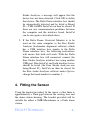
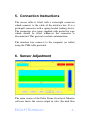
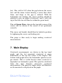
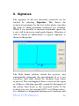
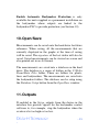
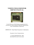
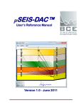
!"
# $
%
&
'!(
!"
Contents
1.
About the Delta Dome Overtravel Monitor ............ 3
2.
System requirements ............................................... 4
3.
Software Installation ............................................... 4
4.
Fitting the Sensor .................................................... 5
5.
Connection Instructions........................................... 7
6.
Sensor Adjustment .................................................. 7
7.
Main Display ........................................................... 8
8.
Signature................................................................ 10
9.
Setup...................................................................... 11
10.
Open/Save ......................................................... 13
11.
Outputs .............................................................. 13
12.
Support .............................................................. 14
-2-
1. About the Delta Dome Overtravel
Monitor
The Delta Dome Overtravel Monitor provides safe and
accurate measurement of dome (bottom former)
overtravel. It is easy to fit to the bodymaker and
measures every stroke at any bodymaker speed during
normal continuous running.
There are two hardware variants available. The first is a
portable device for use as a setup tool. One unit can be
used for measuring dome overtravel on any bodymaker
in the plant.
The other variant is a permanent installation on every
bodymaker in the line. The electrical hardware including
a touch screen computer can be installed in existing
control cabinets or in a dedicated enclosure close to each
bodymaker. Outputs from the device are linked to the
bodymaker PLC to stop the bodymaker if the overtravel
goes out of spec.
The software is the same for both variants.
-3-
2. System requirements
Windows XP , 7 or 8 (32 or 64 bit)
1MB Ram
Compatible with touch screen devices
3. Software Installation
1. Run the install.bat file. This creates a folder
named Delta Dome. The Delta Dome Overtravel
Monitor application file (DD.exe) will be located
here. Create a shortcut to the DD.exe file on the
desktop for ease of use.
2. Run the icalsetup.exe file and follow on-screen
instructions to install InstaCal. (Note, if installing
on a computer that already has InstaCal, such as a
computer that already has the Free Stroke
Analyser software installed, this won’t be
necessary).
3. Connect the interface box to the computer using
the USB cable supplied. Wait until the hardware
is detected and installed by Windows (should take
less than a minute).
4. Run InstaCal (select Start > All Programs >
Measurement Computing > InstaCal). If another
device has previously been used, such as the Free
-4-
Stroke Analyser, a message will appear that the
device has not been detected. Click OK to delete
that device. The Delta Dome interface box should
be automatically detected and be listed as Board
#0 – USB-1608FS. InstaCal can then be closed. If
there are any communication problems between
the computer and the interface board, InstaCal
can be run again as described above.
5. If the Delta Dome Overtavel Monitor is to be
used on the same computer as the Free Stroke
Analyser (bodymaker alignment software) which
has a USB interface box similar to the Delta
Dome interface box, the following instructions
will ensure that both will work: With the Delta
Dome interface box still connected, connect the
Free Stroke Analyser interface box using another
USB port. Run InstaCal and both interface boxes
should be listed (the Free Stroke Analyser one
being Board #1). InstCal can then be closed. In
the Free stroke Analyser software under Options
change the board number to number 1.
4. Fitting the Sensor
Using the bracket provided, fit the sensor so that there is
approximately a 2mm gap between the sensing face and
the dome station housing. The bracket provided will be
suitable for either a CMB Microdomer or a Pride dome
station.
-5-
Fitted to CMB
Microdomer
Fitted to
Pride Domer
The exact position of the sensor needs to be set using the
Delta Dome Overtravel Monitor software to check the
output from the sensor.
The sensor cable needs to be fed out of the bodymaker
guarding. This should be done in such away that the
cable will not get caught on any moving parts and also
not damaged by trapping it between the guards.
-6-
5. Connection Instructions
The sensor cable is fitted with a water-tight connector
which connects to the cable of the interface box. It is a
push-pull connector with a spring loaded locking sleeve.
The connectors also come supplied with protective caps
which should be fitted whenever the connector is
disconnected. This prevents coolant contamination.
The interface box connects to the computer (or tablet)
using the USB cable provided.
6. Sensor Adjustment
The main screen of the Delta Dome Overtravel Monitor
software shows the sensor output in volts (the dark blue
-7-
bar). This will be 10V when the gap between the sensor
face and the dome station housing is more than about
5mm, and drops as the gap is reduced. With the
bodymaker not running, the sensor position should be
adjusted to give an output of between 1 and 3 volts (the
top of the blue bar will then be within the green band).
The red Sensor Posn. alarm in the top right corner of the
screen will be shown if the sensor is not positioned
correctly.
The sensor and bracket should then be locked in position
by tightening the screws and locking nuts.
The gauge is then ready to begin making overtravel
measurements.
7. Main Display
Overtravel measurements are shown in the top trend
graph, and the last measured overtravel is given
numerically in the top left corner of the display. The
bottom trend graph shows the bodymaker speed in cycles
per minute. This is useful because dome overtravel is
dependent on bodymaker speed. The speed in calculated
from the time between successive overtravel
measurements. The speed for single strokes will therefore
not be measured or displayed on the graph.
-8-
The green band in the overtravel graph represents values
between the top and bottom specification limits set in
Setup. If an overtravel measurement falls outside of these
limits an alarm will be given at the top of the display.
The possible overtravel alarms are: Over Spec, Under
Spec or Double Dome. Once activated these alarms stay
on for 20 strokes or until the bodymaker restarts after a
stop.
The Double Dome alarm is given if the change in
overtravel from the previous stroke is more than the
value of Double Dome Sensitivity given in Setup.
There is also a No Overtravel alarm which is given
when no overtravel is detected. This alarm therefore
always comes on when the bodymaker is not running, but
also when it is running but there is no overtravel.
The Sensor Posn. alarm is explained in the Sensor
Adjustment section. If this alarm is shown the gauge may
not measure correctly and the sensor position should be
re-adjusted.
If a measurement is incorrectly made (this may happen
when adjusting the sensor) or if you just want to clear the
data from the graph to start from fresh, measurements
can be deleted by selecting the Delete button.
-9-
8. Signature
The signature of the last measured overtravel can be
viewed by selecting Signature. This shows the
overtravel movement for the last stroke before and after
the point at which maximum overtravel was obtained.
Where it was possible to measure bodymaker speed, the
x-axis will be given in crank angle degrees. Otherwise it
will be shown in milliseconds A typical signature is
shown in the picture.
The Delta Dome software checks the signature and
automatically disregards the measurement if it is not
consistent with what should be obtained from dome
overtravel. This can happen if there is noise on the signal
or if there is vibration (possibly caused by the impact of
the redraw hold down or the overtravel itself). If the
overtravel is very low (around 0.002” or 0.05mm or less),
it is difficult to distinguish between real overtravel and
- 10
-
noise or vibration, so it is worth checking the signature to
make sure the measurement looks like a real overtravel
measurement.
The signature should show the overtravel as a sharp
spike at zero on the crank angle (or time axis),
approximately 2 to 15º (or 1 to 10 ms) wide, depending
on the size of the overtravel (and the speed if the x-axis is
in ms). Any other movement shown on the signature may
be caused by the outer domer, vibration or electrical
noise on the signal.
If the signature shows movement that is not typical, this
may indicate that there is a fault with the dome station.
9. Setup
- 11
-
Max number of strokes can be changed to enable the
overtravel from more or less strokes to be seen in the
graph. It can be set to anything between 50 and 100000.
The software records up to 100000 overtravel
measurements in its memory, and this is not affected by
the value of Max number of strokes. Therefore, it can be
changed to a high value to review the overtravel over a
large period of time (100000 strokes is approximately a
few hours of running), or to a lower value to analyse any
changes in overtravel over a shorter time period. Note,
the trend graph is initially sized to show 50 strokes
irrespective of the value of Max number of strokes, and
this automatically increases as more strokes are measured
until it reaches the value of Max number of strokes.
Double Dome Sensitivity is the amount the overtravel
has to increase between consecutive strokes for the
Double Dome Alarm to be activated. A double dome
refers to the situation where the base of the can is not
stripped off the punch or remains stuck in the dome die.
Sensor Sensitivity has a default setting of 2.6 V/mm and
this should give reasonable accuracy. However, it should
be checked and reset when the gauge is initially used. It
will not require further resetting unless a different kind of
sensor is used or there is a change in the material of the
dome station housing. On-screen instructions are
provided of how to reset the sensitivity. This involves
moving the dome station housing or the sensor a known
distance.
- 12
-
Enable Automatic Bodymaker Protection is only
available for units supplied as a permanent installation on
the bodymaker where outputs are linked to the
bodymaker PLC to provide protection (see Section 10).
10. Open/Save
Measurements can be saved onto the hard drive for future
reference. When saving, all the measurements that are
currently displayed in the graphs at the time of saving
will be saved. The signature of the last stroke will also be
saved. Saved measurements can be viewed on screen and
also printed out in an A4 format.
The measurements are saved into a database on the hard
drive. The database is a series of folders in the C:\Delta
Dome\Data Files folder. There are folders for plants,
lines and bodymakers. The measurements are saved into
the bodymaker folders. The database can be setup using
the Database Setup button from the Open/Save window.
11. Outputs
If enabled in the Setup, outputs from the device in the
interface box provide signals for the bodymaker control
software to, for example, stop the bodymaker when the
overtravel is too high or too low.
- 13
-
The outputs switch between 0 and 24V. There are 2
outputs. The first will normally be at 24V, switching
down to 0V when there is an overtravel alarm. The
second is set to 0V when the sensor is out of range or the
system is not actively monitoring the overtravel (for
example when Setup, Open/Save or Signature are
selected).
The bodymaker PLC can be programmed to stop the
bodymaker if either output is 0V. It should check on
every stroke except the first 2 or 3 strokes. This is to
allow any alarms to be reset after the first stroke
overtravel is measured. Different messages can be
displayed on the bodymaker fault display depending on
which output is OV. For example, they could be
programmed to say Dome Overtravel Fault and
Overtravel Monitor Inactive.
12. Support
Web: www.deltahtechnology.co.uk
Software updates can be downloaded from the website.
email: [email protected]
- 14
-