1
10
2.3. Wedge and Film
Geometrical model of dosimetric wedge
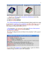
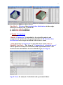
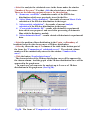
Fig. 7 demonstrates the geometrical model of dosimetric wedge irradiated
with non-diverging EB on moving conveyor. In the Fig.7 two wedges are
stacking together to form a rectangular block. Dosimetric film is inserted
along the sloping surface between two wedges with angle φ made of an
arbitrary materials.
Rectangular block with dosimetric film is located on a conveyer platform
in a such way that length of dosimetric film is coincided with direction of EB
scanning.
Angle φ can be changed in the range from 00 to 900.
The rectangular block can be located on the conveyer platform under
arbitrary angles X relatively incident EB axis in plane of EB scanning XY.
Fig. 7. Geometrical model of dosimetric wedge with dosimetric film
irradiated with scanned EB.
Axis X - direction of EB incidence,
axis Y - direction of EB scanning,
axis Z - direction of conveyer motion.
D-Displacement.
Length of dosimetric film is located in direction of conveyer motion.
Angle φ can be change in the range from 00 to 900.
Angle X can be change in the range from 00 to ±900.
Displacement can be change in the range from 0 to ½ of wedge length.
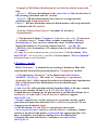
Input data for wedge and film characteristics
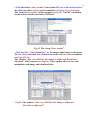
• Click “Target” in the Scheme of MC Module. (See Fig.4.).
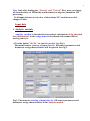
The form for entering of input data for irradiated Wedge (Film and
wedge) will be opened (See Fig.8).