1
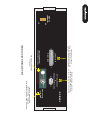
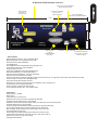
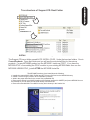
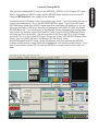
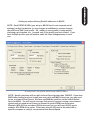
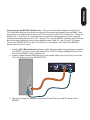
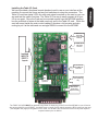
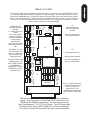
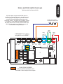
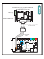
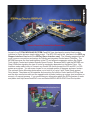
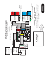
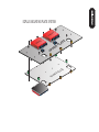
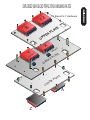
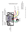
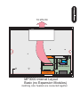
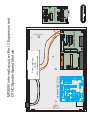
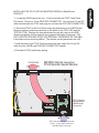
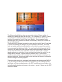
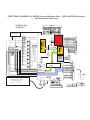
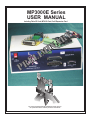
MP3000E Series
USER MANUAL
Including Table I/O Card, MTA100 Card, Port2 Expansion Card
R
P
L
E
Y
R
A
N
I
M
I
All content Copywrited 2005 by CandCNC. All rights reserved.
No repoduction allowed without permission of CandCNC
UBOB II™
Technology
9
Single Cable serial interface to remote
Power Supply and Drive cabinet.
Gives ESP to MACH interface
SERIES E
6
5
+5 VDC
SERIAL PASSTHROUGH
to
ESP CONTROLLER
1
+12 VDC
ommon
C
Single Cable interface to MTA100
terminal card for interface to Motor
drives of EZPlug Cards
to
MTA100/ESP
AXIS I/O Out
PORT2 PASSTHROUGH
(NO CONNECTION)
Plug-in for
UNIVERSAL POWER PAK
REAR PANEL FEATURES
POWER ADAPTER
Single 9 Pin Cable interface to the MPG101B
OPTIONAL Hand Controller
(PORT2 CARD Installed)
*
MP3000E INTRO
OFF
INTERNAL
POWER
ON
INTRODUCING THE MP3000 Master Control Unit
Optional PORT2
Expansion for
Hand Controller
Connection for REMOTE
Table I/O Card for
Inputs and Outputs
MP3000 INTRO
Built-in Self Test for EXPANSION
Modules verifies operation
Input for EXPANSION
Modules (DTHC, SPINDLE SPEED)
10.062
Multi-Axis Interface
Push
Read
MP3000
PORT2 OPTION
DTHC / SPS
3.266
TEST
EXPANSION
MODULE
INPUT
Isolated Table I/O
5
1
6
Multi-Axis Interface
SERIES E
Hand Controller
UBOB II™
Technology
Port1 INPUT
SINGLE PORT
Interface
PORT EXPANDER
Technology
To PC
CP PWR
9
SERIAL INPUT
To PC
Indicator for Charge Pump active
True RS232 Serial signals
Used for DTHC and ISS-02
Interface to MACH
Basic Features
Expanded Single port interface + serial (True RS232 signals)
Modular design allows for easy upgrades and easy repair
Bi-directional communication with MACH3
100% Digital Control
Field Ungradable to DTHC or Spindle Speed with single plug-in card
Custom Screens allow 100% control form MACH3
Charge Pump Active Indicator
Unit is plug compatible with other quality CandCNC products
Buffered Step & Direction (4 or 5 axis operation options)
All 8 power outputs double buffered: all 9 inputs opto isolated
Rear Panel connector for MPG (hand controller)
Exclusive remote Table I/O card makes hooking up homes and limits quick and easy. Two High Current relay outputs at the table where they belong.
All connects made via standard data cables (DB25 & DB9)
Universal Power Pak allows operation world wide
Works with any TTL level step & dir type motor drives including ALL versions of Gecko drives
Included interface card for multiple output options
Quality components. Designed and built in the USA.
Two Year Warranty Parts and Labor. Free unlimited support
DTHC Features
Voltage control to + - 1/4 volt
Built-in self test
Usable with hand or machine torches
Optional Arc Good sensor for machines not equipped with that signal.
Presettable volts from MACH3 screen or from Cut Profile.
Unlimited Cut Profiles store/recall critical settings; Select your material from a list. Edit.Add new profiles
Full DTHC operation from one screen in MACH
TOTAL DC (analog) ISOLATION between Plasma (Tip Volts) and computer/controller logic
On-the-fly push button adjustment for Preset Volts allows dynamic height adjust
New “TIP SAVER” feature has Head Lock to prevent diving on turns or over voids
Last setting retained on power down
Advance Digital Torch Height Controller responds thousands of times per second
Advanced logic functions like Auto THC enable, Torch off on Fault, Stop on fault, etc
Optimized for use with touch-n-go surface sensing
Compatable with SheetCAM
Installation and setup of your MP3000.
There are a series of steps you must complete to setup and interface the
MP3000 with your PC and Your Plasma torch
· Install and setup the Primary parallel port in your PC
· Setup and configure the first serial port (COM1) on your PC
· Install MACH3 software
· Copy your MACH3 license into the MACH3 main folder
· Run the install program from the CandCNC disk to load custom
screens and setup files and Plug-ins
· Open MACH3 and check screens and configure the PLUG-INs
· Connect the 2 PC port cables (one 25Pin, one 9 Pin) to the front of
the MP3000
· Connect the Table I/O card to the Table I/O port on the front of the
MP3000
· Connect the Axis I/O Card to the motor drive modules, or the EZPlug
Gecko cards (stepper or servo) via the provided MTA100 Card
· Run a quick series of tests to confirm the ports are working and that
MACH3 is configured correctly
· Do final checkout.
· Setup and test any Expansion Cards (DTHC or Spindle Speed)
· Fire up the machine and cut a test file.
GENERAL SETUP
The setup of the MP3000 Series Interface involves the installation of
MACH3 software and some support files on the PC to be used for the
machine controller. While we will guide you through the setup for MACH3
the MACH3 manual gives more in depth instructions on each feature.
Familiarize yourself with the controls on the MP3000 and with the loading
and operation of MACH3 with the proper profile. The initial part of this
manual is devoted to getting MACH3 properly installed with the right
support files and profile to run the MP3000. After you have the software
installed and the cables and satellite cards hooked up you will be guided
through a series of tests to determine if everything is working. We ask that
you go through the setup and manual in the order presented. If at some
point you cannot get the expected results and check your connections and
setup with no success then call our tech support person (also the engineer,
assembler, tester, webmaster and marketing guy!) at 903-364-2740. While
we work a lot of strange hours we may not always be available to answer
the call so leave a detailed message of the problem and how to get in touch
with you will hear back from one of the staff.
NOTE: USE THIS SECTION ONLY IF YOUR PC DOES NOT HAVE A BUILT-IN
PARALLEL PORT and/or SERIAL PORT OR YOU HAVE PURCHASED THE
MPG101B HAND CONTROLLER THAT USES A SECOND PARALLEL PORT.
Use the same procedure to install a primary (PORT1) Parallel Port (if your
PC does not have one) or a second port. Do not attempt to use two
separate parallel port cards of the same type to get two ports. For two
ports use a Dual Parallel Port card. CandCNC stocks low cost parallel and
parallel/serial PCI expansion cards.
Make sure the card you install has drivers for the version of Windows you are
running. Win2000 drivers may or may not work in XP (or visa versa). When you
install the card in your computer and turn it back on, it should find the new
hardware and when prompted, you should use the disk that comes with the port
card to install the correct drivers. There should be instructions with the card on
the proper way to install the drivers.
After you install the parallel port and Windows recognizes the port(s) then open
the device manager from the Hardware section under Windows /Control
Panel/System and open the Ports icon and find the Port entries. Open that and
click on the resources tab.
Write down the first number in the Input/Output range (DE00 in this case above). We will
have to enter that number in the MACH3 setup procedure later
PC HARDWARE SETUP
INSTALL and SETUP PRIMARY and/or SECONDARY PARALLEL
PORTS
You will have to setup the COM1 serial port in Windows. It should be setup with
9600 baud, 8 bits, no parity, 1 stop bit, no Flow control.
Testing: We will test the functionality of the com port after we hook up the
MP3000 to the computer.
PC HARDWARE SETUP
INSTALL and SETUP PRIMARY and/or SECONDARY PARALLEL
PORTS
Software Install Instructions
If you are installing from the Support CD you can find the MACH3 ver 3.042.020 in the BladeRunner\MACHPROG folder as Mach3VersionR3.042.exe. If you are installing from a web download you will first have to UNZIP
the files you downloaded and place them in a Folder on your PC. Name the folder something that you can easily
identify later. Unzip the files all into that folder (MACH3 program, BladeRunner-Install.exe, etc)
While MACH will run under Windows Vista a lot of other programs you may need won’t. Vista uses LOT’s of
resources so your PC needs to be the fastest one with 2G of RAM to have a shot at making it work. We do not
currently support Vista so PLEASE don’t call and ask for support for MACH from us if you are running anything
but WIN2000 or XP (any level).
A NOTE ABOUT HARDWARE (PC) THAT YOU NEED TO RUN MACH:
1. Not all hardware is compatible with MACH3 regardless of how fast the PC is. It’s rare that a PC rated over
1.8GHZ won’t run MACH but not unheard of. Usually the problems show up as jerky motor movements, bad
motion in running code and other control problems. Things like Inputs and Outputs and not getting any motor
movement is NOT typically a MACH / PC issue. If in doubt about the ability of the PC run DriverTest.exe (With
MACH not running) located in the MACH3 folder.
2. The minimum computer recommended is a 1 GHZ processor with 256MRam. We find that a 1.8 or 2.4 GHZ
with 512M RAM tends to work better especially if the MB has on-board video. The higher you can run the core
freq in MACH the more Steps per Second you can get and the smoother the pulse train of those steps. There
are also Windows processes that can effect the timing in MACH. Never run realtime virus protection or other
“tray” programs not needed for basic Windows functions.
Start Install of MACH3 software by clicking on the MachProgram/MACH3ver3.042.020.exe file . If you already
have a version of MACH on the PC, you will be prompted to upgrade the version. Let it upgrade. If you have a
version NEWER than 3.042.20 then be aware that while there will probably be no problems we have not tested
the custom drivers (plug-ins) with versions after 3.42.020. You will see the screen above when you start the
install.
PC SOFTWARE SETUP
INSTALL MACH SOFTWARE
Setting up the Port 2 address. (Used only if you have installed a second
parallel port) for use with the MPG101B Hand Control. The new UBOB
interface card used in all CandCNC products has a Port Expander that
increases the number of IO signals and eliminates the need for a second
parallel port unless you are adding the optional Hand Controller. It’s
recommended you do not install the Hand Control unit until you have the
MP3000 working correctly and cutting from the screen and keyboard.
Within MACH3 on the Ports and Pins/ Port Setup and Axis Selection tab:
·
·
·
·
If you are using a motherboard parallel port for PORT1 , confirm the
address is 0X378 in PORT address box in MACH
If you are using a PORT1 or PORT2 expansion card, Enter the hex
address you recorded earlier for your parallel port(s). The actual address
you have written down should be proceeded by a
”0X” (Zero, X) so something like DE00 becomes 0XDE00 for the input
value (or 0xde00 will work since the value is not case sensitive)
For PORT2 installs Make sure the “Use Pins 2-9 as Inputs” box is checked
If the port1 address is correct the CP (Charge Pump) LED should be on
when MACH3 is out of RESET. If it does not come on, then Port 1 may not
be working correctly. We have found that some older Parallel Port add-in
cards do not work properly with XP. Make sure your card has specific
drivers for the version of Windows you are running.
PC SOFTWARE SETUP
About the MACH3 License
You must copy your MACH3 license (provided when you purchase a full copy
from the Mach3 website or from an authorized dealer) into the main MACH3
folder. A MACH2 license will work as well. You can check to make sure your
license is active by re-loading MACH3 after the license copy and opening the
Help/About and making sure the “licensed to” line is NOT “Demo”. The
MP3000E-DTHC( THC functions) WILL NOT WORK WITH A DEMO copy of the
software. The other motor drive functions will work. If you cannot get the THC
button to show active (green LED), then check your copy to make sure the
license is there. If you upgrade the version, the license will remain but if you
manually remove the MACH3 folder or change it’s name prior to loading a new
copy the license file will have to be re-installed into the working directory.
INSTALLING CandCNC Custom drivers, profiles and screen sets.
The Support CD has a folder named AUTO INSTALL FILES. Under that are two folders. One is
CurrentProducts. Open that folder and you will see the auto-install files for the various
products. For any MP3000E product run the MP3000E -Instal.exe FIRST. If you have the
MP3000-DTHC or are adding the DTHC module to your existing MP3000-Basic then run the
MP3000E-UBOBII-DTHC_Install AFTER the MP3000E-Instal file.
.
The MP3000E-Instal.exe Auto Install does the following:
Installs the custom MACH XML (Profile) and SET (Screen file) files into the MACH3 directory
Installs 2 custom Plug-ins used in all of CandCNC’s products .
Adds in the proper side files for the screen files (embedded VB)
Removes the default Icons MACH installs on the Desktop (except for LOADER) and puts a MP3000 Icon on
the Desktop so you can start your MP3000 directly from that ICON.
! Removes unneeded XML’s from MACH so they don’t show up in the Loader List.
!
!
!
!
PC SOFTWARE SETUP
Tree structure of Support CD: Root Folder
After you have installed MACH and run the MP3000E_INSTALL on the Support CD, open
MACH using either the MACH Loader and the MP3000-Base selection from the list OR
using the MP3000-Basic Icon created in the desktop.
You should see the following screen or something very close. If you are missing the icon or
it’s not in the selection list, re-run the MP3000E-INSTALL again. If you have the Profile
(MP3000-Basic) listed in the MACH Loader and the screen does not display go to the top
menu bar and select VIEW/Load Screens and naviagate to the MACH3 folder and select
MP3000-Basic.set. If it is missing any of the Bitmaps (picture buttons and/or backgrounds
then confirm the Installer created the CandCNC folder under the MACH3/Bitmaps Folder
and there are files in that folder. We have included a ZIp file on the CD of all the bitmaps
and the ZIP file is on the CandCNCSupport Forum site in the FILES/MP3000 Support Files
Folder. You can UNZIP the files in the Bitmaps.ZIP file directly to the
MACH3/Bitmaps/CandCNC folder. Along with bitmaps and other features the MP3000
screens contain several custom functions embedded as code behind certain buttons. If you
elect to use another screen SET file with the MP3000 be aware some functions may not
work.
PC SOFTWARE SETUP
Load and Testing MACH
NOTE: Each PROFILE (XML) you setup in MACH has it’s own separate set of
settings (config) it maintains, so any changes or additions to a setup changes
the profile and ONLY that profile. So, adding in a port profile, tuning motors,
changing a pin function, etc, is saved only in the profile you have loaded. If you
have multiple profiles you will need to make the listed changes/setup in each
one.
Checking PORT1 and (optional) PORT2 Setup in MACH CONFIG
NOTE: Not all computers will run with a Kernel Speed greater than 35000HZ. If you start
MACH after loading our Auto Install (see next page) and MACH locks ups you may need
to run at a lower Kernel Speed. We have modified the install to set the default Kernel
Speed at 45000. You will need to increase that speed if you are running a servo based
system and you need more Pulses per Second to get the RPM from the motors.
Example: With 500 line encoders (2000 pulses per rev) you will need 66,000 pps to
produce 2000 RPM of the motor. Pulse rates over 60,000 need to be tested with a
specific computer to verify it can operate at that Kernel Speed.
PC SOFTWARE SETUP
Setting up and confirming Parallel addresses in MACH
MACH Setup
CHECKING PLUG-IN LOAD
The auto install program should load
the ccc_comm and ccc_UBOB plug-ins
and Enable them. Some installs will
also load the ccc_pendant as well. If
you do not have an MPG101B Hand
Controller then disable (RED X) the
ccc_pendant plug-in if it is Enabled.
Open the CONFIG (yellow tab) on the
ccc_comm and set your environment
up to match the products you are
running. You can start with “Neither”
in both selection lists. Later if you add
the DTHC or Spindle Speed Modules
the install SHOULD change the settings
but always check to make sure the
changes were made. If you have a
DTHC (MP3000-DTHC) and have loaded
the DTHC upgrade install and the DTHC
does not appear to be communicating
with the screen (MACH) check the
settings in the ccc_Comm plug-in.
There are currently no settings to
change in the ccc_UBOB plug-in
TABLE I/O
MP3000 Interface Control
Parallel
Ports
AXIS I/O
Sensor Cable
30A Relay
15A Relay
15A Relay
Remote E-Stop
Safety
Table Limits
Homes
POWER SUPPLY
MOTOR DRIVES
Single DB25 Cable
Single DB9 Cable
Mounted on table
REMOTE
Single DB25 Cable TABLE I/O
CARD
NOTE: Entire MP3000 can be installed inside the
Power Control Enclosure. A
Special mounting plate and kit is
available from CandCNC
Serial
Port
Single DB9 Cable
PC
FIGURE 5
SPINDLE
SPEED
OR
THC
SENSOR
MP3000 Setup
To Table Motors
Mounted at plasma or VFD
MP1000 Master Controller Interface Block Diagram
REMOTE Power
& Motor Drive
Box
Note: ESP & EZPlug modules
are sold
as separate items
MOTOR
DRIVER
MOTOR
DRIVER
EZPLUG
Stepper/servo
cards
MOTOR
DRIVER
Motor DC
ESP Smart Power
Module
Single DB25 Cable
MTA100
CARD
Buffered
Step & Dir
X5
Note: MTA100 Extension Card comes with
MP3000 Units
MP3000 Interface Control
FIGURE 6
MP3000 Setup
Components Available
from CandCNC
Main Fuse
Main Switch
AC Line IN
MP3000 to Power Supply & Motor Drivers
FAN
> Plugging in Universal Power Pak
> Checking PWR LED
> Installing External I/O Cards
> TABLE I/O Setup (Homes, Limits, Relays)
> MTA150 Setup (Motor Driver, S&D signals)
> Motor Driver Options
> Setting up outputs
> OPTIONAL PORT2 Interface (port 2 signals)
> Connecting MP3000 to
> Wiring options fo
>
>
MP3000 Setup
HARDWARE SETUP
MP3000 Setup
INPUT POWER
100 - 240VAC 50/60 HZ
Standard IEC
POWER Cord
Use correct cord for
Plugs in your country
For UBOB Builders Kits the plug must be removed (cut off)
and the wires stripped back for use with the input screw
terminals on the UBOBII card (see illustration). There are 4
wires + a shield. The two Yellow rires are BOTH + 12VDC.
The Two RED wires are BOTH +5VDC. The sheild is
Ground (common) for all 4 power wires. See the power
hookup on next page.
Cord supplied is for North America
AC Plugs (120 60HZ)
If you are using the MP3000 on another voltage (like 220VAC 50HZ) you
will need to change out the plug on the end of the supplied cord. You
can also use an IEC cord with the proper connector to fit the wall socket
you need to connect to. IEC cords are the same cords used on Personal
Computers. There are no switches or settings to change on the Power
Pak when changing voltages of line frequency.
The Mini-DIN plug on the Power Pak has 4 pins inside a
circular connector. The plug has a locator pin and only plugs
in one way. Rotate the plug unit it fits the POWER ADAPTER
input jack and plug it completely in. Make sure the AC Cord is
in the other end of the Power Pak and the unit is plugged into
a live AC socket. After you plug in the DIN connector. Turn on
the INTERNAL POWER swtich and turn the MP3000 around so
you can see the front. Confirm that the Green PWR Led is ON.
It should turn on and off when the INTERNAL POWER Switch
is turned ON/OFF
Plug-in for
UNIVERSAL POWER PAK
POWER ADAPTER
ommo
C
PORT2 PASSTHROUGH
(NO CONNECTION)
ON
n
UBOB II™
Technology
+12 VDC
+5 VDC
OFF
INTERNAL
POWER
AXIS I/O Out
5
1
6
9
SERIAL PASSTHROUGH
to
ESP CONTROLLER
to
MTA100/ESP
SERIES E
Multi-Axis Interface
Push
Read
MP3000
TEST
PORT2 OPTION
EXPANSION
MODULE
DTHC / SPS
INPUT
Isolated Table I/O
5
1
6
Multi-Axis Interface
SERIES E
Hand Controller
UBOB II™
Technology
Port1 INPUT
To PC
CP PWR
9
SERIAL INPUT
To PC
PWR should be on when rear
Switch is ON. CP lamp DOES
not light until MACH is
connected to PC and MACH is
out of RESET
MP3000 Setup
Plugging in the International Power Pak to the MP3000
MP3000 Setup
Connecting up the MP3000 Interface box. Take a look at the block diagram drawing (Fig 5
THC Installation Manual), that gives an overview of the control box, plasma unit and table. Note
that there are two cables that run from the PC and connect to the THC Controller box. These are
labeled Port 1, and Serial It’s important that you connect the first parallel port in the computer
(normally the existing printer port or LPT1 port) to Port 1 on the MP3000 Controller box There are
also three other cables that connect three satellite cards (Table I/O, Axis I/O and THC Sensor
Card) to the MP3000-DTHC as well. The Table I/O is connected on the front of the MP3000
directly above the Port 1 input
PC Parallel Port 1
Serial Port
1. Install a DB25 Male to Female extension cable (All pins straight through) between parallel
port (PORT1 on the PC to the part marked Port 1 INPUT (Orange highlight below) on the
front of the MP3000-DTHC controller unit.
2. Install a straight through DB9 cable (not a null modem cable) from your Com1 port on the
PC to the Serial port on the MP3000-DTHC
3. See the next page for using the International Power Pak to provide DC power to the
MP3000
MP3000 Setup
Installing the Table I/O Card.
We have provided a functional remote breakout card to use as your interface at the
machine to connect the Home and any limit switches via crimp-on connectors. The
Table I/O card has status LED's for each main signal mounted on the card so you can
see and test the switch functions. The Table I/O is a way to easily connect all of your
I/O at one point. Since the Card can be mounted remote from the MP3000 Interface
box the multitiude of wires at the table need only pull to the Table I/O card.. While the
card will mount inside the main control cabinet it requires a lot less wire and wire
routing to put it at the table and use a single DB25 to connect it to the MP3000.
K3 MAIN RELAY
20A COM
Normally OPEN
Terminal
K3 MAIN RELAY
20A COM
Terminal
Isolated
INPUTS
PORT 1
Inputs
K4 Aux RELAY
20A COM & NO
Terminals
EPO
Jumper for
operation
BHome and AUX
inputs [PORT 2]
only
IDC Header for
DB9 adapter.
Quad Relay
Expansion Plug
The TABLE I/O CARD MUST be attached to the Table I/O Input plug on the Front of the MP3000 or you will not be
able to bring MACH3 out of RESET. You MUST have a jumper (or NC switch) across the EPO jumpers on the card
(see diagram next page) to bring MACH out of reset. You do NOT have to have the Homes or any other inputs or
outputs hooked up to run MACH.
The TableI/O card provides a breakout of inputs and outputs. It connects to the UBOB/MP3000 via a 25
pin computer cable into the TABLE I/O plug (see overlay next page). The card can be close to or up to
20ft from the UBOB/MP3000. You have the option to mount the card close to the UBOB, with the Motor
drivers in the main controller box, and pull the Homes and other inputs into the card, or you can mount the
card out on the Table and connect all of the inputs with short runs. Having the Power relays out on the
table for larger machines can be an advantage.
D3
DANGER!
J5
K3
ZHome
K3
Main Relay Output
20A Normally open
contacts
See hook up details for
driving external loads
T17
K3
Com1
T19
AHome
K3
AHome
K4
Secondary Relay 10A
50
C5
K4
J7
J6
J33
J9
J10
T20
T21
C14
T5
J8
52
UP
6
J2
1
PLUG
14
AUX3
J12
AUX4
UP
BHOME
D9
C11
AUX2
J13
J1
T4
AUX0
AUX0
AUX1
EPO
C13C12
See hook up details for
driving external loads.
C10
T7
C9
DWN
T3
DOWN
NO Com2
C1
C6
T9
Normally open contacts.
J4
K4
C7
T8
K4
D2
J11
LIMITS
T2
LIMITS
T6
C8
C&CNC
47 TABLE I/O
REV 6
T18
C4
ZHome
T16
J18
DANGER!
49
T13
T15
T14
D15
T11
T10
ARC OK
YHome
NO
R1
ARC OK
K5
C2
T12
Xhome
C3
The EPO is the E-stop
(software) input. IT
HAS TO BE CLOSED.
A JUMPER IS
NEEDED IF IT”S NOT
USED WITH A NC Estop Button (not
YHome
The DOWN, UP and
ARC OK inputs are
also Port 1 inputs and
can be used for any
switch type input.
Xhome
HOME INPUTS
Use Normally Open
Switches.
X - A Home are port 1
inputs
Limits are typically
setup as normally
closed and connected
in series at the
switches with
beginning and end of
string into the LIMITS
Tabs.
QUAD RELAY
10
1
13
25
AUX 0 - AUX4 and B Home
are PORT2 inputs and only
work if you have the
optional Port 2 card
installed and a 2nd parallel
port on thePC active and
LED’s are indicators that the circuit is working when a switch is
closed. They only come on if the Table I/O is connected to the
UBOB and the UBOB is powered up. You can short across an
input Pair (example: T12 to T13 for X Home. The LED should light
and the X Home Screen LED in MACH for X Home should light.
The LED is in series with the Input Opto and is a good indication
MP3000 Setup
TABLE I/O II CARD
MP3000 Setup
Home and limit switch hook ups
Typical connections for Homes and Limits
All of the inputs are opto isolated and map to a
specific pin on the parallel port(s). In reality you can
use any input for any signal. Inputs are not fast
enough for Encoder feedback faster than a few
pulses per second. The inputs use a “floating” ground
(+12 return). If you need more inputs than the 8 (9
with EPO) then a PORT 2 card can be hooked to the
UBOB and the added Aux and BHome inputs will
work with a second parallel port.
Normally closed contacts
For far limits. Wired in series
NC
C
C
NC
C
YHome
C
NO
XHome
ZHome
T17
T3
UP
T4
EPO
T11
ARC OK
J1
C14
K5
D15
BHOME
AUX1
K3
D3
K4
J13
R1
AUX2
DANGER!
J18
J12
AUX3
J8
AUX4
QUAD RELAY HEADER
is for an optional quad relay card
and adds 4 more relays to the outputs.
J5
NO Com2
Com1
48
C11
J11
DANGER!
R2
NO
J7
K4
J4
C10
Xhome
YHome
D2
C1
10
13
25
C&CNC
47 TABLE I/O
REV 6
J6
T13
K4
C13C12
QUAD RELAY
J33
K3
D9
6
1
J10
T15
ZHome
AHome
LIMITS
DWN
AUX0
UP
14
1
J9
T12
C2
T10
AUX0
DOWN
T2
T19
T20
T21
T14
ARC OK
LIMITS
AHome
C9
T16
C4
C3
T18
ZHome
T6
NO
C
NO
YHome
T5
52
T7
C5
T8
C8
PLUG
C7
C6
J2
T9
C
Xhome
JUMPER EPO to be able to
bring MACH out of RESET
NC
MP3000 OPTION
6 RELAY SETUP USING OPTIONAL QUAD RELAY EXPANSION CARD
or QUAD RELAY BOX
See Quad Relay Manual for Connection details
L2 HOT
BREAKER B
BREAKER A & B
J14
B PLUG HOT
J3
J7
D9
PLUGS NEU
K3
K5
J10
+
SFTY GND
K4
J9
K2
L1 NEU
J8
A PLUG HOT
Outputs for 2 low
Current Relays
QUAD RELAY EXPANSION CARD
34
33
+
BREAKER A
Not Used
J17
1
SKT
J2
Db9 Fem to DB9 Male EXTENSION CABLE
up to 25ft can be used
IDC 10 to DB9 Male
Adapter
AUX0
DOWN
T2
T3
UP
T4
EPO
J1
C14
T11
ARC OK
AUX1
D3
R1
AUX2
K3
J12
K4
R2
J5
AUX3
C11
J18
Com1
48
NO Com2
NO
J4
BHOME
J13
C10
K5
K3
K4
DANGER!
DANGER!
J7
J11
Xhome
D2
J8
AUX4
REV 6
C1
10
13
25
C&CNC
47 TABLE I/O
J6
49
K4
C13C12
QUAD RELAY
J10
J33
K3
D9
6
1
J9
T13
YHome
ZHome
AHome
LIMITS
DWN
AUX0
UP
14
1
T20
T21
T15
T10
T17
T12
C2
ARC OK
LIMITS
AHome
T19
50
T14
ZHome
C9
T16
C4
C3
T18
YHome
T6
Xhome
T5
52
T7
C5
T8
C8
PLUG
C7
C6
J2
T9
USING OUTPUT RELAYS
TABLE IO CARD II
Connect Safety ground (GreenWire) on equipment that has three conductors
DANGER: High Voltage present.
Do not connect with power applied
Hot (L1)
Use wire size rated
for the continuous current of the load
#16 up 5A (10A peak)
#14 up 10A (15A peak)
#12 up 15A (15A peak)
Main Output
Normally Output 1 for spindle motors
20A @240VAC Max
SPST Relay
K3
NO
NC
C
SPDT
10A Max
NO
High Current Load (up to 20A)
Note: Current ratings for wires are approximation ONLY.
Factors such as ambient temps, insulation type, length
of run, bundled or unbundled, etc. make exact ratings difficult.
Use this as a general guide only and follow the recommendations
of your equipment manufacturer. Use at least the wire
size of the equipment cord. Use commercial splices and
heatshrink on all terminals or a sealed electrical box.
Load can be any AC inductive (motors) or resistive (lights) load
up to 20A.
Outputs K4 are rated to 10A max.
#10 up 25A (35A peak)
#8 up 35A (45A peak)
The MTA100 card is supplied wih all MP3000 series units. If you have ordered a
Complete Electronics Package (PlazPak, RouterPak or MillPak) then the MTA150 is
already mounted inside the Enclosure and has a DB25 access plug externally. The
following instructions are based on the MP3000 being sold as a stand-alone
product and shows how to use the MTA150 to connect discrete motor drives or the
CandCNC EZPlug Stepper or Servo Interface cards using single cables for up to 6
drives. If you have the Complete Electronics Package you can skip this section on
the MTA150 Setup and testing.
THE MTA150 connection plug is on the back of the MP3000 and labled as the AXIS
I/O . It takes a single MALE to FEMALE DB25 Extension Cable up to 20Ft long. In
most circumstances the MTA150 card will be mounted in the same case as the
Motor Drives and Power Supply. If you are building a single box control cabinet
and you are embedding the MP3000 outside it’s case inside the enclosure, you can
get a short 26 pin IDC cable to interface directly between the AXIS I/O plug on the
UBOB and the MTA100 card. Please contact us to order the part or check the
website.
S
D
D
J3
Y
S
D
1
B Axis
U6
S
2
1
1
J55
1
2
A
1
+5
PCGND PCGND PC
10
9
J34
ESP Interface
Encoder V
5V Source
BJ1- Y'
20
19
D
1
13
25
1
S
D
Z-A
J19
S&D Test
AXIS I/O IN
AXIS I/O IN
2
REV2
G540 INTERFACE
J52
14
1
J2
To AXIS I/O
on Rear of
MP3000
Z
1
Dir
STEP
X-Y
1
J5
B
CandCNC
S MTA150
REV4
PLUG
DB25 Cable FEMALE end
X
Since the MP3000 can be the front-end in a wide variety of motor driver
configurations we are including several pages of different hookup possibilities.
These will cover most applications.
MTA150 Mounted Remotely in Drive / Power
Enclosure
MP3000 Setup
INSTALLING the MTA150 (Axis I/O) Card for interface to Motor Drives and EZPlug
Gecko Interface Cards (sold separately)
MTA150 Motor Driver Interface Card
The MTA 100 provides a remote (or local) breakout card to access the 5 sets of step & dir signals from
the MP3000 AXIS I/O Port . When placed in a separate cabinet with the Motor Drivers and/or power
supply, the MTA150 can be mounted so the DB25 connector (AXIS I/O In) can be used with a standard
M-F DB 25 extension cable and IDC Adapter at the UBOBII Axis I/O Header to make avaialble all the
signals for using Step & Direction based drives. The Card also has additional connectors that provide
interface to an external G540 4 axis Gecko Driver product and headers to plug in CandCNC EZPlug®
Stepper or Servo Interface cards. Axis I/O interface to the UBOBII can also be via the 26 pin IDC
header behind the DB25 connector labeled as AXIS I/O. 5th Axis (B) signals are provided using the B
channel signals from the UBOBII but independent 5 axis motion (not hardware slaved) requires a 2nd
parallel port card. The following pages show several different type of hookups to common motor drives
and to our EZplug cards. The are for illustration only and should be used as guides.
X
A STEP
S
D
1
J3
Y
D
B Axis
U6
S
1
J55
1
+5
PCGND PCGND PC
10
9
J34
ESP Interface
Encoder V
5V Source
BJ1- Y'
1
Screw Terminals for
Hard wiring Drives
(non-EZPLUG)
STEP
Dir
Dir
D
1
2
S
D
Z-A
J19
S&D Test
J2
13
25
20
19
Z
+5
+5
For +5 Common Drives
PCGND
PCGND
PCGND
For GND Common Drives
(Gecko 203)
PCGND
MTA100 REV2
G540 INTERFACE
J52
2
1
AXIS I/O IN
AXIS I/O IN
1
Z
1
1
14
2
STEP
Y Dir
S
D
X-Y
1
J5
Dir
STEP
STEP
Dir
X
A
CandCNC
S MTA150
REV4
PLUG
B
MP3000 Setup
MTA150 Card not used
in BladeRunner
J1: Sets the source of 5V for Servo Card Encoder.
CAUTION DO NOT CHANGE THIS UNLESS YOU ARE
TOLD to DO SO. This option is for systems running
encoders that draw more than 50ma.
Ours do not. It is USED ONLY WITH SERVO SYSTEMS
1
Dir
STEP
20
19
J3
BJ1- Y'
Encoder V
5V Source
AXIS I/O IN
25
13
Y
Z
A
Different drives may have different common
connections for the inputs. Older G210 and G320
drives are COMMON + 5. Newer G203 Drives are
PCGND
GND
Common
for Gecko 203
Common
See previous page for screw terminal signal names
2
B
1
BLOCK DIAGRAMS
UBOBII
(not to scale)
DB25 <16ft
AXIS I/O IN
10
9
1
X
LOW Cost Interface with discreet wiring
ESP Interface
1
1
J19
2
S&D Test
COM
D
S
GECKO
MP3000 Setup
GECKO A MOTOR
S
D
C
GECKO Z MOTOR
Y MOTOR
GECKO X MOTOR
DC Volts to
Geckos
MTA100 Mass Termination Adapter
MOTOR POWER AND ENCODER (Servo models) CONNECTIONS
NOT SHOWN
203
J2
U6
14
REV2
S
D
G540 INTERFACE
1
Z-A
J34
2
1
D
1
J52
B Axis
1
J5
J55
X-Y
S
D
S
D
S
D
CandCNC
S MTA150
REV4
PLUG
201
320
1
+5
PCGND PCGND PC
201
320
203
MTA100 Mass Termination Adapter
AXIS I/O Plug
FP Card
OPTIONAL
16
15
D6
SMART Power Controller
J9
20
19
+5
2
1
2
1
J4
PSC650-D or PSC1500-D
DB25 <16ft
C1
J55
10
9
10 pin ribbon cables
10”
5V Source
Encoder V
J1
D4
D5
D2
D1
DC Volts to
Interface Cards
1
Typically MTA100 card is located inside
Power Controller
MP3000-BASIC
J19
J18
MP3000-SPS
10
9
2
1
X
Y
Z
A
J20
J21
J22
J23
2
1
10
9
2
1
10
9
S&D CARD
D3
J17
1
2
1
AXIS I/O IN
PSC Interface
MP3000-DTHC
B - Y'
10 pin ribbon cables
10”
1
J2
PC +5
MINI-IO IN
J50
J19
J34
J5
PC GND
RS
J6
J8
J7
Remote Shutdown
U5
J24
J55
1
EXT
Port
CandCNC
MULTI-AXIS INTERFACE
REV1
1
J52
USED WITH MP3000 DTHC, SPINDLE SPEED or
BASIC
Z-A
J25
X-Y
Drive Common
J3
1
GND
*
*
GECKO
GECKO
GECKO
GECKO
GECKO
GECKO
Z MOTOR
A MOTOR
Y Encoder
Y MOTOR
MP3000 Setup
All connections to motors have plug connectors
Furnished with Cards
NOTE: ONLY MP1000B Series Support 5 or 5.5 axis
operation
Hardware
Slaved to
Y
5th Axis
Gecko Stepper
Interface Card
EZPLUG
CandCNC
OR
Gecko Servo
Interface Card
EZPLUG
CandCNC
X MOTOR
X Encoder
MP3000 Setup
Optional
Step & Dir
Monitor
Card
1
10
9
2
Y
Z
A
1
+5
PCGND PCGND PC
1
X
J3
S&D Test
1
BJ1- Y'
Encoder V
5V Source
1
J52
20
19
1
B Axis
J19
2
1
S
1
B
U6
ESP Interface
Dir
STEP
D
G540 INTERFACE
AXIS I/O IN
2
1
1
G540 Drive UNIT
See GECKO Manual for
Motor connections and
Tuning
J5
14
13
AXIS I/O IN
25
TO AXIS I/O
Plug on
UBOBII or
Back of
MP3000> Use
M-F DB25
Extension
Cable for
interface.
Optional IDC to
IDC ribbon
cable for
setups with the
UBOBII close
PLUG
CONNECTIONS TO GECKO 540 4 AXIS MOTOR DRIVER.
NOTE: Only signals used too/from G540 are Step & Dir signals for XYZ & A. All Other I/O signals
(outputs, Homes, Limits etc) are handled by the UBOBII and it’s I/O cards.
J2
Z-A
J34
IDC to DB25 FEMALE Adapter
REV2
J55
X-Y
D
S
D
S
D
S
D
CandCNC
S MTA150
REV4
DO NOT USE the recommended
GECKO 540 Pin setups in the GECKO
data sheet. The UBOB or MP3000
XML for MACH on our Support CD has
the correct pin settings
Screw terminals not used
AXIS I/O CABLE CONNECTIONS MTA100 & MTA150
Connectors
INPUT PINs
Signal
UBOB
MTA 150
1 RX
Serial REC NC
Not Used
2 X Step
X Step
J18 - 1
S-TERM
3 X Dir
X Dir
J18 - 2
S-TERM
4 Y Step
Y Step
J20 - 1
S-TERM
5 Y Dir
Y Dir
J20 -2
S-TERM
6 Z Step
Z Step
J21 - 1
S-TERM
7 Z Dir
Z Dir
J21 - 2
S-TERM
8 A Step
A Step
J22 - 1
S-TERM
9 A Dir
A Dir
J22 - 2
S-TERM
10 PC GND
PC GND
J24 & J25 S-TERM
11 STOP SW
J8 - 6
J9 -15
Not Used
12 GND (PS)
J8 - 2
J9 - 6
Not Used
13 +9 to 12 (PS) J8 - 1
J9 - 5
ESP
14 PC +5
PC +5
J23- 1 & 2 S-TERM
15 Estop - NC
J6 - 1
J9 - 8
ESP
16 Estop - Com J6 - 2
J9 - 7
ESP
17 NC
Not Used
18 B Step
Port2 out
J3 - 1
S-TERM
19 B Dir
Port2 out
J3 - 2
S-TERM
20 PC +12
PC + 12
NC
Not Used
21 TX
Serial XMT NC
Not Used
22 NC
Not Used
23 STOP LED
J8 - 3
J9 - 14
Not Used
24 RUN LED
J8 - 4
J9 - 13
Not Used
25 RUN SW
J8 - 5
J9 - 16
Not Used
Jack numbers are on MTA100 & MTA150 Cards
MP3000 Setup
PINOUT INFORMATION for
MTA100 and MTA150 Interface cards supplied with
UBOB Builders Kit; MP3000 (all models).
NOTE: the chart is for reference only. The proper signals are setup in MACH when using
the profiles (XML) provided. The auto installer will load the correct profiles, screens and
icons.
MP3000 OPTIONS
As part of our TOTAL MODULAR SYSTEM CandCNC has developed a product line to make
interface to Gecko drives a single cable project. The MTA100 card is the interface to the EZPLug
Stepper Interface Card and/or the EZPlug Servo Interface card. The following pages show the
most common connections and setups for building an integrated Gecko based Controller. The
MP3000 becomes the front end interface to the PC and supports expansion options like Digital
Torch Height Control and Isolated Spindle Speed Control. Because MACH and the MP3000 use
Step & Direction signaling the type of motor is completely dependant on the Motor Drive. Our
Interface cards make it easy to connect any Gecko 200 series (except the 250 and 251) or 300
series servo drives. You can even choose to run a mixed system of steppers and servo motors.
The optional Gecko Mounting plates allow you to build 4 (or up to 6 with Triple Stack version)
Drive stacks. The plates act as heatsinks and mounting for both the Gecko and the EZPlug card
and the drive connectors stick out the opposite side to make hooking up motors (and encoders on
servos) a 2 second process. If you would like more information about the EZPlug series of cards
and plates visit http://www.CandCNC.com and Select MODULAR BLOCKS from the top tabs.
Table I/O Card
Optional
Step & Dir
Monitor
Card
D6
16
15
20
19
J4
+5
D5
D4
D2
D1
1
FP Card
DC Motor Volts
48 to 65 VDC
J9
5V Source
2
1
2
1
C1
J19
UBOB
or
MP3000
S&D CARD
D3
J17
DB25 <16ft
NOT TO SCALE
J18
J55
Gecko Stepper
Interface Card
CandCNC
OR
Gecko Servo
Interface Card
CandCNC
GECKO
GECKO
GECKO
GECKO
Z MOTOR
A MOTOR
Y MOTOR
X MOTOR
B - Y'
Encoder V
J1
Drive Common
J3
1
1
GND
DC Volts to
Interface Cards
MP3000 Setup
CandCNC Carries a complete line of card level and box level
Solutions for CNC builders. All our products are design to
work together
All connections to motors have plug connectors
Furnished with Cards
10 pin ribbon cables
10”
Quick and Easy 3 or 4 axis
Controller
10
9
2
1
10
9
2
1
10
9
X
Y
Z
A
J20
J21
J22
J23
J24
2
1
10
9
2
1
AXIS I/O IN
PSC Interface
Parallel Port
MTA100 Mass Termination Adapter
1
J2
PC +5
MINI-IO IN
J50
J19
J34
J5
PC GND
RS
J6
J8
J7
Remote Shutdown
J52
U5
J55
1
EXT
Port
CandCNC
MULTI-AXIS INTERFACE
REV1
1
PC withMACH3
Z-A
J25
X-Y
MP3000 OPTIONS
EZPLUG MOUNTING PLATE SYSTEM
KO
C
GE
O
CK
E
G
R
PE
TE
A
L
P
UP
LO
TE
A
PL
R
WE
KO
C
GE
Y2 Slaved to Y Hardware
Y2
O
G
K
EC
B
R
E
P
TE
A
PL
UP
X
G
YECKO
G
MI
E
DL
KO
C
E
TE
A
L
P
D
R
E
OW
P
TE
A
L
L
A
Z
MP3000 OPTIONS
EXPLODEDVIEWGECKOTRIPLESTACKMOUNINGPALTES
DB25
Passthrough
(IDC to DB25 Adapter)
+5C1& 4+12 INC23
1
J2
14
SWT B
SWT B#
1
Port2
PASSTHROUGH
1
J9
SWT A
SWT A#
J5
SCREWS
GND
8
CandCNC
Power
Interface
REV1
AXIS I/O
+5
SCREWS
+12 GND
To UBOB II
13
25
RJ45
J3
J4
Safety Relay
1
NOTE REV1 Cards only
Support PORT2 Passthrough
on DB25. Not all pins connected
REV2 cards support both
TO UBOBII
PCGND
+12
TO UBOBII
PCGND
+5
Pattern for RJ45 cutout (rear of BladeRunner)
Rear View
DPST Switch
TO DPDT Panel Switch
J11
2
SKT
J7
J6
All pins straight through
Used for AXIS I/O or
PORT2 passthrough to
panel
J10
J12
Remote power On/OFF
Used Only on BladeRunner
Power Commander.
J8
4 PIN MiniDIN
for Universal
Power Pak
Power and DB25 Panel Passthrough Adapter
POWER DISTRIBUTION CARD
USED in MP3000 rear panel
MP3000 INTERNALS
TO MTA100
J2
1
1
1
UBOB
1
U2
PC+5
PCGND
1
PORT2 INTERCONNECT
J7
1
J57
TABLE I/O
+12
FLOAT-GND
REV6
C5
1
J65
J63
POWER
C12
1
J56
J8
U3
+
1
J6
1
AXIS I/O
FEATURE
CONN
UBOB Rev6
C1
J1
14
Upper DB25
PLUG
To
TABLE I/O
PPORT1
1
1
SKT
J29
CP
SERIAL
MP3000 Internal Layout
Basic (no Expansion Modules)
matching color headers are connected together
R2
CP
SIP5
+
4N35
ISO1
ISO4
ISO4
ISO7
ISO2
ISO1
4N35
4N35
FLT GND
+5 FLT
ISO2
4N35
ISO7
ISO3
ISO3
Pin 26 out
Pin 10 out
ISO6
ISO5
4N35
J14
ISO5
4N35
ISO6
26
C&CNC Port2
REV4
J6
J5
+5VDC PCGND
U21
U21
PORT2
I/O
J3
J3
U25
SIP1
J10
Port2 INPUT
2
1
Optional PORT 2 Card
26
J8
1
J7
J2
NCP
PWR
2
1
4N35
CON26
J63
14
1
J65
PLUG
PPORT1
AXIS I/O
TABLE I/O
Power Interface
CARD
Axis I/O passthrough
J56
+
J1
1
J57
CP
U3
C1
1
U2
C12
FEATURE
CONN
POWER
REV6
UBOB
PC+5
FLOAT-GND
+12
PCGND
SERIAL
SKT
J29
UBOB Rev6
C5
PORT2 INTERCONNECT
MP3000 INTERNALS
DTHC Module
MP3000 Internal Layout w/ Port 2 Expansion and
DTHC/Spindle Speed Module
1
1
1
MPG-101J1
1
1
25
MPG
J2
1
1
1
PORT2 FROM UBOB
J7
1
1
R1
27
J4
24
J8
J6
1. Locate the UBOB card in the unit. It is the card with the PORT1 and Serial
Port inputs. There is a 16 pin FEATURE CONNECTOR. Use the short 16 pin IDC
cable included with the DTHC and plug one end into the FEATURE CONNECTOR
2. Mount the DTHC to the Front Panel using the jackscrews on the DB9 Socket.
Remove both hex jackscrews and line up the holes for the TEST LED and the
TEST BUTTON. Replace the hex jackscrews through the front into the DB9
Socket and tighten until the board is snug against the inside of the panel. DO
NOT OVERTIGHTEN AND STRIP THE INTERNAL FASTENERS ON THE DB9!
It will make secure mounting difficult. The threads on the jackscrews are 4-40.
3. Hold the back of the DTHC Card and insert the other end of the 16 pin IDC
cable from the UBOB card FEATURE CONNECTOR Header.
4. Proceed to DTHC preliminary testing
MP3000 Internal Layout w/
DTHC/Spindle Speed Module
TO MTA100
J2
1
UBOB
1
1
U2
PC+5
PCGND
1
PORT2 INTERCONNECT
1
J7
1
J57
TABLE I/O
+12
FLOAT-GND
REV6
C5
1
J65
J63
POWER
DTHC Module
C12
1
J56
J8
U3
+
1
J6
1
AXIS I/O
FEATURE
CONN
UBOB Rev6
DTHC Module
Mounts Above
UBOB Serial
Connector
C1
J1
1
1
14
PLUG
SKT
J29
CP
PPORT1
SERIAL
AC Switch
DTHC Mounts through Front panel
Cutout. 16 pin cable connects to
UBOB Feature Connector
MP3000 INTERNALS
INSTALLING THE DTHC INTO AN EXISTING MP3000 or BladeRunner
PRODUCT
4N35
4N35
J4
C3
ISO6
CP
C4
C3
J14
CON10
X-Connect
J14
+5 FLT
FLT GND
J5
2
1
ISO5
ISO7
J10
+
J6
PCGND
Not Used
J7
+5VDC
Light Gray inputs
NOT USED
ISO2
Port2 INPUT
ISO1
4N35
ISO7
4N35
ISO1
4N35
ISO6
ISO4
ISO2
ISO4
4N35
ISO5
ISO3
ISO3
4N35
C&CNC Port2
REV4
To PC PORT 2 via
M-M DB25 Extension
C4
2
1
U20
J8
CP LED
PWR
1
J2
NCP
U21
10
9
IDC to DB25 Female
Adapter
U20
J3
IDC to DB9 Male
FOR MPG101B Hookup
MPG-101
1
2
1
PORT2 I/O
MPG
26 to 26 IDC Ribbon Cable
1
J3
1
+12 K7
J57
TABLE I/O
K8
PORT2 INTERCONNECT
Axis Slave
J60
FLOAT-GND J59
UBOB
J65
PCGND
REV1
PC+5
FLOAT +12
J61
1500MFD 16VDC
J58
POWER
J63
J62
AXIS I/O
PWR
1
C1
FAN
PPORT1
SERIAL
CP IND
PLUG
PORT1 DB25
FEATURE CONN
1
MP3000 OPTIONS
ADDING AN OPTIONAL PORT2 CARD FOR I/O EXPANSION
The ribbon cable connectors
may not have a key to prevent them from being plugged in backwards
X
Pin 1 stripe
Stripe goes to side with PIN1
PIN1
NOTCH
PIN1
NOTCH
Typical Ribbon reader
Pin 1 stripe
X
IF you unplug an internal cable note the stripe or specific color of the pin 1 wire on the ribbon cable
make SURE you plug it back in so that the cable is oriented as shown.
MP3000 INTERNALS
IMPORTANT NOTE ON INTERNAL PLUGS:
Now, multiply the motor steps times the drive ratio. A reduction (most used) is the step down
ration (like 3:1) so it would be (200 X 3) or 600. If the leadscrew for example has to spin 5 times
to move one inch multiply the above number by 5 (600 X 5) or 3000. We now know it takes 3000
pulses to move our load 1 inch (obviously if your table is setup in MM then all of the units will be
in MM.)
The last number we have to provide is the step frequency of your motor drives. Lets say you are
running in ¼ step mode. It will take 4 times as many steps to rotate the motor so you also
multiply by the step factor (4 in this case) to get a final answer of 12,000 steps per inch.
If your drive is rack and pinion you may find that the multiplication number is less than one. For
example where one revolution of the pinion moves the axis 1.36 inches we need a factional
rotation of the pinion to move 1 inch. The number will be one divided by the distance you move in
one pinion revolution. For the above pinion example you get 1/1.36 or .7352941 (.7353 is close
enough).
That becomes you multiplier for the table ratio so for the above example (given the same belt
reduction and steppers the answer would look like this:
(200 X 3)(.7353) or 441.18 pulses
The last number we have to provide is the step frequency of your motor drives. Lets say you are
running in ¼ step mode. It will take 4 times as many steps to rotate the motor so you also
multiply by the step factor (4 in this case) to get a final answer of 441.18 X 4 or 1764.72 steps per
unit.
You have to do the calculation for each axis and enter the number in MACH3. Make sure you do
a “SAVE AXIS” (button) on each axis as change them.
For velocity (unless you already know what that should be) enter a conservative number like 120
(120 inches per minute or 120 IPM) and for acceleration use a number of 2X the velocity (240
inch/min/sec). NOTE: Accelation units in MACH are in units/sec/sec so DIVIDE by 60 (240
Inches/min/sec = 4 inches/sec/sec.
These numbers and settings are just to get the machine where you can check the operation of
the MP3000 and should be refined before actually trying to make any test cuts.
MACH3 Setup
Setting the initial Steps per Unit in MACH3 motor tuning.
Every table will have different Steps per unit, velocity (max speed) and Accleration settings. To
do testing on the table you must determine the correct settings for your table. Use the following
method:
For Steppers:
1. Determine the number of steps your motors need to make one full revolution
(Normally 200 for most steppers)
2. Determine the ratio of any belt reduction between the motors and the mechanical
drive on your table.
3. Determine the drive ratio of your mechanical drive (how far does the leadscrew
or pinion move the load with one revolution.
4. Determine the step frequency of you drives (Full, half, quarter, 1/8, etc)
NOTE: All Gecko stepper drives are 1/10 (10X) microstepping
Motor Tuning Screen in MACH3
Testing the MP3000 for motor control
After you have connected the Axis I/O (MTA150) pins to the proper Motor Driver
pins and installed the Table I/O card, you will need to check the proper function of
those pins. In order to get motion and you need to have MACH3 running with it out
of E-stop and the CP LED on the front panel active (ON). Without CP active, you
will not get motion.
·
·
·
·
·
·
·
·
Make sure all of the cables are connected.
Power up the MP3000
Load Mach3 with the proper profile (MP3000-Basic) and Screen
Hit the Reset button. The LED over the Reset in MACH will turn solid
Green
The CP LED on the front panel of the MP3000 will turn solid Yellow
Make sure power is on to your motors.
Use the keyboard arrow keys to jog your machine. Don’t worry if they jog
the wrong way with the keys or the wrong axis jogs. We will fix that later.
Default jog keys are UP & DWN Arrows are Y jog; Left & Right Arrows are X
and Page Up and Page Down are Z up and down.
The Optional test Step and Direction Monitor will confirm that the signals are
getting out to the MTA150 card. If the LED’s flash and you are not getting
movement the problem is between the MTA150 and the motor drivers.
MACH3 Setup
For proper tuning of MACH3 please refer to the MACH 3 manual. The exact
tuning of the software is beyond the scope of this document.
Note each axis has a Step and Direction pin. To swap the X and Y axis simply
swap both parameters. In the example above the step pin for X would be
changed to 4 and the direction to 5 while the Y would be 2 and 3 respectively.
At this point do not worry if the axis moves in the wrong direction, simply
that you have the axis as you define them correct.
The next step is to make the axis movement agree with the DRO and g-code
commands for that axis. The DRO (Digital Read Out) for each axis is at the top
of the screen. You will need to take MACH3 out of E-stop by pressing the Reset
button.
·
Jog your machine so the cutting head is away from the limits (approx
center of the table is good). Don’t worry if the jog keys aren’t correct or
that the DRO’s are running in the wrong direction.
·
If your machine is setup so that one corner is X0,Y0 (lower left corner?)
then all moves away from 0,0 should be a positive (increasing) number.
MACH3 Setup
Setting up the proper axis direction and motor tuning
While the Profile file (MP3000-Basic.XML) provided with the MP3000 sets up all
of the pins there are several things we don’t know about your machine and so
certain parameters have to be set based on your specific machine. A good
example is which axis you may define as X and Y. There are two ways to swap
the axis definitions. You can rewire the motor drives (physically move the step
and direction signals at the motor drive, or swap the step and direction pins in the
setup of MACH3. In either case you need to first get your definition into the
setup. To swap the definition in MACH3, open the Config menu off of the top
menu bar. Open Ports & Pins and click to open the Motor Outputs Tab.
The MDI is a line to allow you to type in direct g-code commands to make
the machine make specific moves. You don’t need to have a deep
knowledge of g-code to use it for testing.
(Your MDI may look different)
·
·
·
·
·
When you type in a g-code command it is not case sensitive but be sure to
use zeros’s and not “O’s” for the numbers! At this point do not worry
about which hotkeys are assigned to a direction.
With the machine out of e-stop and power on, type the following into the
MDI Frame:
o Move the screen cursor to the MDI frame and click on it. The frame
background color should change to yellow meaning it is ready for
input. No other movement keys work when the MDI frame is
selected.
o G00 X3.0
o Enter key activates command
The X axis should move 3 inches(mm) in some direction It should have
moved away from your established X zero and the DRO numbers should
have increased. If it did not, then you need to reverse the direction of axis
travel.
To reverse the direction of any axis open the Ports and Pins/ Motor
Outputs and change the polarity of the Dir LowActive setting for that axis.
Clicking the Green Checkmark or the Red X will swap the definition. Red
X is positive and Green Check is negative polarity.
Work with each axis to establish that the movement direction is correct.
Use the MDI frame and change the axis letter from X to Y then Z.
Change the polarity of the step signal (Should always be Green
Checkmark for drives that use a +5 common [Gecko 201; Gecko 320]
and a RED X for drives that use a GND common [Gecko 203])
MACH3 Setup
·
A word about homing: It works well to have each axis with a Home switch
and to make that position “0” (absolute zero) for that axis. The Z with a
floating head (discussed in the DTHC Manual) is an exception.
By having it setup X and Y as 0,0 you can always re-establish you position
on the table. There are circumstances where the DRO position can vary from
the actual machine position. An example is if you do an e-stop during a cut.
That form of stop, stops the machine instantly and any code in the look-ahead
buffer is dropped.
The only way to be certain you have not lost position is to home each axis
and reestablish where 0,0 is. The homing in MACH3 is setup using the menu
under Config/Motor Home/Soft Limits
(Note: the example above is for our machine and may vary for yours!)
There are several parameters of interest. If you click the Ref X button next to the
X DRO on the Main Screen the machine should start moving towards the home
switch for that axis at the speed listed in the Speed % column for that axis. If it
moves in the wrong direction flip the polarity of the Home Neg value. You will
have to close the menu to test the move. Make sure all axis’s move towards the
home switch for that axis when the button is activated. The machine should
move to the home switch, the switch should make contact and the movement
should stop and MACH3 will back off the switch slightly to “un-make” it. You can
use the Diagnostics page in MACH3 to “see” the LED for each axis come on as
the switch is made and then go off. All limit LED’s should remain off unless the
switch is activated. You can test each switch manually by pulling up the
diagnostics screen and manually clicking each switch on your table and watching
the LED’s.
If your switch location is not where you want X and Y table zero’s (0,0) to be then
you can tell MACH3 what offset you want to use. Normally the offset will be a
negative number since it says “this axis switch is past the established zero point
on the table”. The 20% homing speed that is default works well. You do not
want to home at high speeds as accuracy (repeatability) will suffer.
MACH3 Setup
The final step is to open the Config/System Hotkeys menu and for each
direction select the keyboard hotkey you want to use for that direction of
travel. Now when you press that key the machine should jog in the proper
direction. There are lots of other parameters in the menus. For more
information about them use the MACH3 manual.
1. With Mach3 running and the MP3000 powered up we are going to go
through a series of tests that will confirm the unit is operating.
2.
NOTE: If the screen is not correct or any buttons or the background is
wrong/missing make sure that the CandCNC directory was created under the
Bitmaps directory of MACH3 and that the MP3000-Basic.set file has been
installed in the Main MACH3 folder. DO NOT USE THE 1024.set file that comes
with MACH3 or any of the default MACH profiles or SET files.
Confirm the operation of the Table I/O card. Make sure it is connected
and that you have your table Home switches connected as shown in the
diagram. Open the Diagnostics screen in MACH3 and watch the “M Home”
group of status LED’s at the upper right side of the screen. If you are going to
use Limits then wait until you have the other functions checked and running.
Confirm proper operation of outputs. The 2 outputs can be tested using the
screen buttons. (NOTE: Outputs 3 and above only work if you have the Optional
Quad Relay Card/Box with the added relays or are using the Expansin Cards
(DTHC or ISS-02). If you have those cards or this is an MP3000-DTHC or
MP3000-SpindleSpeed unit the install for those features (done AFTER the initial
MP3000-Install) changes outputs around and makes the Torch or the VFD the
primary Output and the two aux relays move down to ouput 2 and output 3
respectively Turning on an output should turn on it’s associated relay.
Make sure everything jogs in the right direction and moves the correct distance
as indicated by the DRO’s.
To check calibration on a given axis move the axis close to it’s home (0) point
and zero the axis DRO. Using the MDI window send that axis out a given length.
The longer you make that the more accurate the measurement can be.
EXAMPLE: Move X 36 inches by G00 X36.00 in the MDI. AFTER you zero X.
Measure with a ruler or tape measure that is accurtate to 1/32 (.03125). Read
the tape. If it’s short/long of 36” write down the actual measurement. Return the
axis to it’s set 0 by using G00 X0.00. THEN calculate the percentage you are off
in the units (inches/mm) and change your Steps per Unit value by the same
percentage. You may end up with fractional (decimal) steps. Put them in up to 4
decimal points. Run the test again and if you are still off continue to make small
adjustments in the Steps per Unit unit it is dead on at the longest distance you
can move on that axis.
MACH3 Setup
Confirming proper operation
The XHome should light up when you manually activate X Home switch. It
should be off when the switch is not active. If it is reversed (i.e. goes OFF when
you activate the switch but stays on otherwise) you will need to reverse the
polarity of the switch in Ports & Pins/ Input Signals. We recommend using
normally open (NO) contacts on Homes and Normally Closed (NC) contacts on
the far limits (if used).
The far limits (NC contacts) are wired in series into the Limits Table I/O card and
it is setup so breaking the string at any point activates a hard limit. The hard
limits are safety switches located at points on the table to prevent the machine
from going past the table travel limits. You can have far limits (opposite the 0,0
location of the table) AND near limits (at points where the machine would crash
on the other side of the Home switches. Limits are optional and on stepper
based systems you could elect to have just hard stops since the motors can be
stalled without damage. Servos present a different issue. There can be
conditions where a servo will “run away” like if an encoder wire comes loose or
becomes defective. Servos are harder to stall and can self-destruct if allowed to
stall and voltage is still being applied.
There are other options for using table limits besides just shutting down MACH3.
If you are using our ESP series of Power Controllers you can actually wire the
hard limits up to the provided inputs on the ESP controller and an activation of a
limit will actually shutdown all power to the motors….period. Please see the ESP
manual for details.
1. Start by doubling your max VELOCITY on the X and Y axis
NOTE: If you are using a 4 motor setup and software slaving you're A axis to X or
Y then you need to provide both motors with the same velocity and acceleration
numbers. While the Steps per Unit should match you can change that slightly to
account for mechanical mismatches. Do not run different gears or belt reduction
ratios on a slaved axis or you will have a lot of problems getting them to exactly
match.
2. Use the calibration technique of typing in a move in the MDI (G00 move) to a
point then measure the error. Keep raising both Velocity and Acceleration for each
axis by about 20% jumps. At the point you hear the motors start to grind or you
start losing position,(or getting a drive fault on a servo system) write down the
settings. Back off 20% first on velocity. You would like to have as much
acceleration as you can maintain at an acceptable velocity. If you still get lost steps
or drive faults then lower the acceleration by 20% and try again.
3. Once you have one axis tuned use the same settings on any axis that has the
same motor and gearing and run the tests. You can move it up or down but having
a Y that is twice as fast as X won’t help much in normal moves since it only moves
as fast as the slowest axis during a coordinated move.
4. The Z is normally tuned and calibrated differently than the horizontal axis. Often
the Z uses a leadscrew and the calculations are easier. For Gecko’s it’s 2000 times
the number of threads per inch = Steps per Unit. The constant 2000 is the motor
steps times the microstepping (200 * 10). For servos we supply the encoder line
count is 500. That produces 2000 pulses per rev so the numbers work the same.
You may find you have to increase the MACH Kernel Speed (Ports & Pins main
tab) so you can get enough steps per unit to hit higher velocities.
If you plan on using your machine for Torch Height Control or for 3D carving having
a fast Z is an advantage. You want to have speed but also good resolution. Make
the Z feed too course and the THC moves can be ragged and cause overshoot. A
good resolution is about .001 per step (.025mm). A velocity of at least 150 IPM is a
target but speeds of at least the velocity of X an Y let you cut 3D a lot faster.
Steppers only spin about 600 to 800 RPM lifting the Z so to get 150IPM your
leadscrew needs to not be finer than 5 TPI.
TESTING
Once you have the motors moving the right direction and the right distance then
you should go through a tuning procedure to optimize the machine movements.
Running the first test cut.
Watch it cut air and make the moves. If you want to have some fun tape down a
large piece of pape or cardboard and chuck a marker into the Z head and reset the Z
zero so that when the marker tip is touching the Z DRO reads -.100 inches. Run the
RoadRunner again
The DTHC Digital Torch Height Control or the ISS-02 Spindle Speed Modules have
their own setup and operation Manuals. You should first run the auto installs for
those devices. It will setup a new profile and load different screen sets. You should
be aware that each MACH profile has it’s own settings including all of the motor
tuning and homing, hotkeys, etc. To get those settings into a new profile open the
working profile you just completed and either write down the settings or do screen
grabs you can refer to. Transfer all of the settings to your new profile.
AT THIS POINT YOU SHOULD REFER TO THE APPROPRIATE MANUALS
IF
You have an Expansion Module or Option not covered in this manual
See the Manuals Section of the CD for specific product manuals. You can also find
manuals on our website at http://www.CandCNC.com/Manuals.htm
TESTING
To save frustrations and money do your first G-code run with the Z zeroed a n inch
or two above actual material/table height. Open the G-Code folder in MACH and run
the RoadRunner.tap file but using the File Load G-code option.
ADDENDUM SECTION
>
PINOUT CHARTS
>
BLOCK SCHEMATIC (UBOB)
PINOUTS for TABLE I/O Card to UBOB Connector
The Profiles provided and installed during the Auto -Install setup the proper pins in
MACH for normal functions. The charts are provided for troubleshooting and for
users looking to do a custom interface.
INPUT PIN
1
2
3
4
5
6
7
8
9
10
11
12
13
14
15
16
17
18
19
20
21
22
23
24
25
Name
LIMIT
ARC OK
AUX 1
AUX 2
GND Float
GND Float
AUX 3
AUX 4
K5
K4
K3
K2
K1
X Home
Y Home
Z Home
A Home
+12 PC
+12 PC
EPO
UP
B Home
AUX 0
DOWN
K6
TABLE I/O CARD
PORT- PIN
Jack/Term
PORT 8 - 11
PORT 8 - 12
PORT 2 - 4
PORT 2 -5
PORT 2 - 6
PORT 2 - 7
IDC10 - 6
10 Amp T-I/O
20 Amp T-I/O
IDC10 - 5
IDC10 - 8
PIN 11
PIN 12
PIN 13
PIN 15
PIN 10
PORT 8 - 13
PORT 2 - 2
PORT 2 - 3
PORT 8 - 15
IDC10 - 9
On T-I/O
On T-I/O
T9
J9
T8
T7
IDC10 Header is located on card (10 pin IDC header) for
interconnect to Quad Relay Box. PORT 8 and PORT 4 are
VIRTUAL Ports (shared) in MACH3. PORT 2 listed inputs only
work if a PORT 2 Card and a 2nd parallel port in the PC is used
and setup correctly.
PINOUT CHART for MTA100 & MTA150 card Connectors
AXIS I/O CABLE CONNECTIONS MTA100 & MTA150
Connectors
INPUT PINs
Signal
UBOB
MTA 150
1 RX
Serial REC NC
Not Used
2 X Step
X Step
J18 - 1
S-TERM
3 X Dir
X Dir
J18 - 2
S-TERM
4 Y Step
Y Step
J20 - 1
S-TERM
5 Y Dir
Y Dir
J20 -2
S-TERM
6 Z Step
Z Step
J21 - 1
S-TERM
7 Z Dir
Z Dir
J21 - 2
S-TERM
8 A Step
A Step
J22 - 1
S-TERM
9 A Dir
A Dir
J22 - 2
S-TERM
10 PC GND
PC GND
J24 & J25 S-TERM
11 STOP SW
J8 - 6
J9 -15
Not Used
12 GND (PS)
J8 - 2
J9 - 6
Not Used
13 +9 to 12 (PS) J8 - 1
J9 - 5
ESP
14 PC +5
PC +5
J23- 1 & 2 S-TERM
15 Estop - NC
J6 - 1
J9 - 8
ESP
16 Estop - Com J6 - 2
J9 - 7
ESP
17 NC
Not Used
18 B Step
Port2 out
J3 - 1
S-TERM
19 B Dir
Port2 out
J3 - 2
S-TERM
20 PC +12
PC + 12
NC
Not Used
21 TX
Serial XMT NC
Not Used
22 NC
Not Used
23 STOP LED
J8 - 3
J9 - 14
Not Used
24 RUN LED
J8 - 4
J9 - 13
Not Used
25 RUN SW
J8 - 5
J9 - 16
Not Used
Jack numbers are on MTA100 & MTA150 Cards
G540 Output J52 From MTA150
PIN
Signal
1 NoConnect
2 X Step
3 X Dir
4 Y Step
5 Y Dir
6 Z Step
7 Z Dir
8 A Step
9 A Dir
10 E-Stop
J50 - 15
11-17 No Connect
18-25 PC GND
G540 Uses Motor Signals Only. All other signals pass through
UBOB Card
PORT2 INTERFACE CARD is an OPTION and normally used with the MPG101B
Pendant and a 2nd parallel port in the PC to provide the added I/O needed. Because
the MPG101B only uses 6 of the 11 available inputs the other inputs become available
as auxiliary inputs The charts below show the pin assignments and the connector
pins on the PORT2 Interface 25 pin connectorr
IDC PIN
1
2
3
4
5
6
7
8
9
10
11
12
13
14
15
16
17
18
19
20
21
22
23
24
25
PORT 2 INTERFACE CARD
PARALLEL
SIGNAL
PORT 2 PIN TYPE
+5VDC
N/A
DB9-1
INPUT 12
PIN 12
DB9-2
INPUT 11
PIN 11
DB9-6
INPUT 13
PIN 13
DB9-4
INPUT 10
PIN 10
DB9-5
INPUT 2
PIN 2
OPTO
INPUT 9
PIN 9
DB9-7
INPUT 14
PIN 15
DB9-9
INPUT5
PIN 5
OPTO
INPUT 3
PIN 3
OPTO
INPUT 4
PIN 4
OPTO
GND PC
18-25
DB9-3
INPUT 6
PIN 6
OPTO
INPUT 7
PIN 7
OPTO
INPUT 8
PIN 8
OPTO
+9VDC Float
N/A
PWR
INPUT 11
PIN 11
INPUT 12
PIN 12
OUT 1
PIN 1
DB9-8
OUT2
PIN 14
STEP
OUT 3
PIN 16
DIR
OUT 4
PIN 17
GND (Float)
N/A
PWR
GND(Float)
N/A
PWR
CP - WatchD
N/A
UBOB SIGNAL
+5
N/A
N/A
N/A
N/A
B HOME
N/A
N/A
AUX 2
AUX 0
AUX 1
GND PC
AUX 3
AUX 4
N/A
+9VDC
N/A
N/A
N/A
B STEP
B HOME
N/A
GND FLOAT
GND FLOAT
Charge Pump
Signals are listed by the pin on the IDC 26 pin header on the PORT 2 card that
normally connects to the PORT2 Interface on the UBOB. Signals of type DB-# are
shared with DB9 signals in table above. They are not connected at the UBOB
end.
DB9 PIN
1
2
3
4
5
6
7
8
9
PORT 2 CARD DB9 Connector
SIGNAL
PORT 2 PIN
TYPE
+5VDC PC
N/A
N/A
Input 12
PIN 12
COMP
PC GND
N/A
Input 13
PIN 13
COMP
Input 10
PIN 10
COMP
Input 11
PIN 11
COMP
Input 9
PIN 9
COMP
Output 1
PIN 1
BUFF
Input 14
PIN 15
COMP
UBOB SIGNAL
Inputs listed as COMP are Comparator Inputs with a 50% Noise threshold. NonIsolated. Inputs Listed as OPTO are Opto Isolated
The MPG101B plugs into the DB9 on the PORT2 Card. On some units
the PORT2 card may be installed in the MP3000 and the connectors
accessed through the panel. The pin functions are as shown. See the
following page to determine the pin numbers on a certain Plug type.
PIN IDENTIFIER for DB25 & DB 9 Connectors
MALE DB25
PINS
2
1
13
10
14 15
25
20
FEMALE DB25
Socket
13
2
10
25
15 14
20
DB 9 MALE
PINS
5
1
6
9
1
FUNCTIONAL SCHEMATIC of UBOBII Universal Breakout Card. USED in MP3000 (all series)
and Bladerunner (all series)
UBOBII BLOCK
SCHEMATIC
DC-DC
Converter
AXIS I/O
CON26
SI P2
330 X 8
J1
Shift-In
ISOLATED INPUTS
XStep-IN
XDir-IN
YStep-IN
YDi r-IN
ZStep-IN
ZDir-IN
AStep-IN
ADi r-IN
E-STOP
MUX 1
MUX 2
MUX 3
RCK
MUX 4
SCK
CP
I/O
BUFFER
DISABLE
DRIVERS
U2 A
PS25 01-4
XH ome
U2B
PS25 01-4
YHome
ZHome
J3
14
15
16
17
18
19
20
21
22
23
24
25
1
2
3
4
5
6
7
8
9
10
11
12
13
PCGND
U2C
PS25 01-4
AUX I N 2
U2D
PS25 01-4
AHom e
1
2
3
4
5
6
7
8
9
10
11
12
13
14
15
16
17
18
19
20
21
22
23
24
25
26
PORT1 DB25
J29
9
8
7
6
5
4
3
2
1
U3 A
PS25 01-4
DB25 Table I/O
RS232
SEND/
REC
Limits
CP
U3B
PS25 01-4
PCGND
REC
TX
AR C-OK
CON9
VCC_+5
U3C
PS25 01-4
R1
DISABLE
THC -UP
OUTPUT MUX
CIRCUIT
BHome
LATCH
U3D
PS25 01-4
X6
AUX 2
AUX 0
AUX 1
PC GND
AUX 3
AUX 4
THC- Down
K3
K2
K1
RELAY
DRIVERS
EPO
K4
K6
K5
+ Floating
AUX 1
AUX 2
AUX 3
AUX 4
BHom
AUX 0
B Step
B Dir
+12VDC
1
2
Floating GND
J6
ESP-EPO
WD(CP)
UNIVERSAL AC-DC SUPPLY
100 - 240 VAC 50 /60 HZ
J9
J7
+12
+5
+5 @ 1A + 12 @ 1.2A
1
2
3
4
5
6
7
8
9
10
11
12
13
14
15
16
17
18
19
20
21
22
23
24
25
26
+12
D18
JUMPER
LED
J2
1
2
FAN
R8
1K
BStep-P2
CP IND
XDir
YDir
BDir-P2
EXPANSION PORT
1
3
5
J63
2
4
6
Slave DIR
XStep
YStep
1
3
5
J65
2
4
6
Slave STEP