1
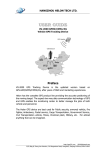
CONTENTS
PICPLC16B KEY FEATURES
CONNECTING THE SYSTEM
INTRODUCTION
Switches and Jumpers
MCU Ports
Power Supply
On-Board USB 2.0 Programmer
Power Supply Supervisor and Reset Circuit
Reference Voltage
RS-232 Communication
RS-485 Communication
On-Board Serial Ethernet
Optocouplers
Relays
Direct Port Access
4
5
6
7
8
9
10
11
12
13
14
15
16
18
20
4
PICPLC16B KEY FEATURES
1.
2.
3.
4.
5.
6.
7.
8.
9.
10.
11.
12.
13.
Power ON/OFF switch;
Power supply 16-30V DC or 12-22V AC;
Isolated power supply for optocouplers;
Optocouplers inputs;
Optocouplers;
DIP switches SW4 and SW5 used to enable/disable
connection between optocouplers and MCU;
Development mode jumpers;
Reset push button;
USB connector;
On-board 2.0 USB programmer;
RS-232 communication port;
Reference voltage;
A/D converter input;
14. RS-485 communication port;
15. MCU socket with PIC18F4520 microcontroller;
16. DIP switch SW1 used to enable/disable pull-up/pulldown resistors on PORTA and PORTE pins;
17. DIP switch SW2 used to enable/disable RS232, RS-485
communication and MOSI, MISO and SCK lines;
18. DIP switch SW3 used to enable/disable Ethernet connection;
19. Direct port access connectors;
20. Ethernet communication port;
21. DIP switches SW6 and SW7 enable/disable relays;
22. Relays;
23. Relays outputs; and
24. Change over contact.
Apart from this manual, the PLC (Programmable Logic Controller) system box contains
PICPLC16B system, product CD, USB cable, RS232 cable and user's manual for the
PICPLC16B. In order to use the PICPLC16B properly, it is necessary to go through the following steps:
Step no.1
Take your development system and product CD out of the box. Insert the product CD into CD drive. Please, do not connect development system to PC yet.
Step no.2
Install PICFlash2 programmer software to enable a program to be transferred from PC to the microcontroller chip. Installation instructions are con/
tained in the ‘PICFlash 2 programmer’ manual.
Step no.3
Install USB drivers on your PC to enable programmer's hardware to operate properly on the PICPLC16B board. For detailed installation instructions refer to the 'Installing USB drivers' manual.
Step no.4
Connect the PICPLC16B to external power supply and, for programming,
to PC using USB cable. Please use one of USB ports on the back of the PC
because they are directly connected to the computer motherboard.
The first time you switch the PICPLC16B on, your PC will automatically
detect a new hardware. You will be immediately prompted whether Windows should search for new drivers update or not. Select the option 'No, not
this time' and click 'Next'. Another window appears, click 'Next' and the
operating system will automatically find the drivers. Click 'Finish' to complete this process and run PICFlash 2 as explained in ‘PICFlash 2 programmer’ manual.
Next time you switch the PICPLC16B on, Windows will not ask for new
drivers update during driver installation.
.
After these four steps, your PICPLC16B is successfully installed and ready for use. You can
read a program from the chip or write a new one into it. The product CD provides numerous
simple program examples that will make your first steps Easy...
5
CONNECTING THE SYSTEM
CONNECTING THE SYSTEM
INTRODUCTION
6
INTRODUCTION
PICPLC16B is a programmable logic controller design to control devices in industry and
automatics using relays. It has a built-in programmer so that there is no need for additional
hardware for the microcontroller programming. Besides, this controller has inputs isolated by
optocouplers, 12-bit A/D converter, RS-232 and RS-485 communication modules and Ethernet communication module as well. Four IDC-10 male connectors enable the PICPLC16B to
be directly connected to the microcontroller pins, if needed.
Figure 1 illustrates the PICPLC16B development system. As seen, there are identification
marks next to each component on a silkscreen, both on the top and bottom. These marks
describe connections to the microcontroller, operation modes and provide other useful information so that there is almost no need for additional schematics.
Figure 1 PICPLC16B
SWITCHES
The PICPLC16B development system features a number of peripheral devices. In order to
enable them before programming, the appropriate jumpers or switches have to be properly set.
Switches are mechanical devices used to establish or break connection between two contacts.
The PICPLC16B development system has seven groups of switches.
Figure 2
Switch group SW1
Switches 1, 2, 3 and 4 are ON,
whereas 5, 6, 7 and 8 are OFF
DIP switch SW1 is used to enable external pull-up/pull-down resistors on PORTA and PORTE;
DIP switch SW2 is used to enable/disable lines between RS-232 module (RX232 and TX232),
RS-485 module (RT485, RX485 and TX485) and communication lines (MISO, MOSI and SCK);
DIP switch SW3 enables Ethernet connection;
DIP switches SW4 and SW5 enable/disable optocouplers inputs; and
DIP switches SW6 and SW7 enable/disable connection between MCU and relays.
JUMPERS
Similarly, jumpers are used to break or establish connection between two points. Under the
plastic cover of a jumper, there is a metal contact which establishes connection when the
jumper is placed over two pins.
Jumper is commonly used as a selector between two possible connections via 3-pin connector. As illustrated in Figure 3, the middle connector pin can be connected to the left or right
pin, depending on the jumper’s position.
Jumper is not
placed and
middle pin is
unconnected.
Figure 3
Jumper as a selector
Jumper is placed
on the right side
connecting middle
and right pin.
Jumper is placed
on the left side
connecting middle and left pin.
SWITCHES AND JUMPERS
7
8
MCU PORT
The PICPLC16B comes with 40-pin microcontrollers PIC18F4520 in DIP40 package.
MCU PORT
The microcontroller pins are routed to various peripherals. All
ports are directly connected to Direct Port Access Connectors
which are normally used for connecting external peripherals to
the board or as points for connecting digital logic probes.
Some pins are connected to other peripherals such as optocouplers,
RS-232 communication, RS-485 communication, etc.
Figure 4
PICPLC16B MCU Port
Figure 5
System connection
POWER SUPPLY
9
Power supply for PICPLC16B board can be AC or DC. AC power supply voltage ranges
between 12 and 22V, whereas DC power supply voltage ranges between 16 and 30V. Isolated
power supply for optocouplers is denoted by OCVCC on the board. Figure 6 illustrates power
supply connector.
Figure 6
Power supply connector
Figure 7
Power supply circuit diagram
POWER SUPPLY
The PICPLC16B can use two independet power supply sources. One of them is PICPLC16B
board power supply and the other is isolated power supply for optocouplers.
ON-BOARD USB 2.0 PROGRAMMER
10
ON-BOARD USB 2.0 PROGRAMMER
There is no need to use external equipment during programming as the PICPLC16B development system has
its own on-board USB 2.0 programmer.
All you need to do is to connect the system to PC using
the USB cable, enable Development MODE by setting
jumpers J1, J2, J3 and J4 in the left hand position and
turn the power switch on.
Use the PICflash2 programming software, supplied with the
board, to load a program into the microcontroller.
Figure 8 USB 2.0 programmer
Figure 9 USB 2.0 programmer circuit diagram
In industrial environment it is very important to have a reliable device capable of performing
under different conditions. The most important issue for all electronic circuits is a stable
power supply. However, in harsh environments there can be some deviations from the power
supply nominal values. A power supply supervisor monitors power supply level and restarts
the microcontroller if it is too low or too high. It can also be connected to reset button, thus
generating reset signal when the button is pressed.
Figure 10
Power supply supervisor
Figure 11 Power supply supervisor circuit diagram
11
POWER SUPPLY SUPERVISOR AND RESET CIRCUIT
POWER SUPPLY SUPERVISOR AND RESET CIRCUIT
VOLTAGE REFERENCE
12
VOLTAGE REFERENCE
Voltage reference is an electronic circuit that produces fixed (constant) voltage, which in our
case amounts to 4.096V. It is used in both Analog-to-Digital (ADC) and Digital-to-Analog
Converter (DAC) to specify input and output voltage ranges.
Figure 12
Voltage Reference
Figure 13
Voltage reference circuit diagram
RS-232 COMMUNICATION
RS-232 communication enables point-to-point data transfer. It is commonly used in data acquisition applications to
transfer data between the microcontroller and PC. Since the
voltage levels of the microcontroller and PC are not directly compatible with each other, a level converter such as
MAX232 must be used.
Figure 14
RS232 connector
Figure 15 RS232 circuit diagram
RS-232 COMMUNICATION
13
RS-485 COMMUNICATION
14
RS-485 COMMUNICATION
RS-485 communication enables point-to-point and point-to-multipoint data transfer. It is commonly used to enable data transfer
between several microcontrollers. LTC485 interface transceiver is
used for transforming signal on microcontrollers Rt, Rx and Tx
lines into a differential signal on A and B lines.
The PICPLC16B development board has one RS-485 communication device. In order to provide more flexible system, the microcontroller is connected to LTC485 via three switches (3,4 and 5) of
DIP switch SW2.
Figure 16 RS-485 communication
Figure 17 RS-485 circuit diagram
ON-BOARD SERIAL ETHERNET
Ethernet is a most commonly used Local Area Network
(LAN) technology today. On the top of physical layer,
Ethernet stations mutually communicate by sending data
packets to each other. Each station is assigned a single 48bit MAC address which is used to specify both destination
and source of each data packet.
Figure 18 Ethernet connector
Figure 19 Ethernet circuit diagram
ON-BOARD SERIAL ETHERNET
15
OPTOCOUPLERS
16
OPTOCOUPLERS
The PICPLC16B has 16 optocouplers inputs. Optocouplers are widely used in industrial
applications where inputs must be galvanized, i.e. electrically isolated from the rest of development board. The main idea is to protect the microcontroller from voltage spikes that might
occur on input lines.
Figure 20 Optocoupler group
In order that input circuit is electrically isolated from the rest of board, it must have its own
power supply (12V DC). The optocoupler chip has one LED on each input and one open collector transistor on each output pin. The first 8 optocoupler outputs are connected to the
microcontroller PORTA and PORTE, the other 8 optocouplers outputs are connected to the
microcontroller PORTC. PORTA(E) and PORTC must be driven high by putting jumpers J5
and J7 in the upper position.
OPTOCOUPLERS
17
Figure 21 Optocoupler circuit diagram
RELAYS
18
RELAYS
In order to control devices which use high power for their operation, the PICPLC16B has 16
relays connected to the microcontroller PORTB and PORTD. The relay coil voltage amounts
to 12V DC (+U12).
Figure 22 Relays
The microcontroller PORTB and PORTD pins cannot provide enough current necessary to
directly run relays and they are connected to the ULN2804 Darlington drivers, therefore.
Ports RB and RD must be driven low, i.e. pulled-down, so that relays can be switched on when
the microcontroller sets a logic one
on any of its outputs. Each relay has
one LED connected in parallel with
its coil. It is used to indicate whether
the appropriate relay is active or not.
Reley outputs consist of three contacts: normally-open, normallyclosed and change-over, thus
enabling any device to be connected
to it.
For example, if you connect a light
bulb as per Figure 23, it will be
turned on by relay activation, i.e.
whenever appropriate MCU output is
driven high.
Figure 23 Light bulb connection
Figure 24 Relays circuit diagram
RELAYS
19
DIRECT PORT ACCESS CONNECTORS
20
DIRECT PORT ACCESS CONNECTORS
All microcontroller input/output pins can be accessed via IDC-10 (2x5) connectors placed
along the right side of the board. For each microcontroller port, there is one 10-pin connector
providing up to eight port pins and two additional pins connected to VCC and GND.
These connectors can be used to connect the system to external devices such as Serial
Ethernet, Compact Flash, keyboard etc. If external and on-board peripherals use the same
pins, then on-board peripherals must be disconnected from the microcontroller by setting the
appropriate jumpers/switches. The connectors can also be used for attaching logic probes or
other test equipment.
Figure 25 Direct port access connectors
Figure 26 Flat cable connector
DIRECT PORT ACCESS
21
Figure 27 Direct port access circuit diagram
Figure 28 PORTB connector
Ethernet connector
RS-485 module
connector
ADC connector
4.096V Voltage
Reference
RS-232 module
with selectable
TX and RX
Power ON/OFF
switch
Relays
Optocouplers
Relays output connectors
External power supply
16-30V DC 12-22V AC
Power supply
supervisor
Optocoplers
input connectors
MCU in DIP40 package
Reset push button
USB 2.0 programmer
with mikroICD
PICPLC16B
Direct port
access
Jumpers to
determine input
pin performance in idle
state (connected to pull-up or
pull-down resistors)
USB 2.0
connector