1
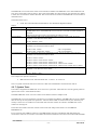
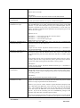
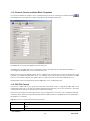
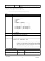
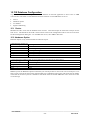
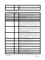
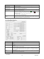
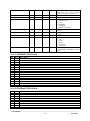
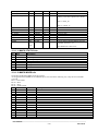
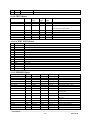
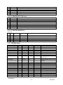
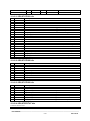
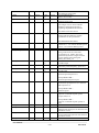
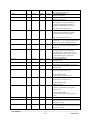
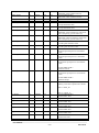
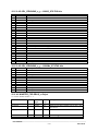
operator. Use bit 0 – 15
e
Only
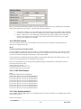
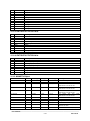
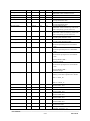
See MORD bits table below
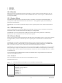
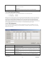
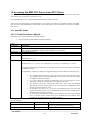
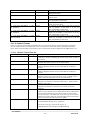
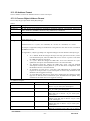
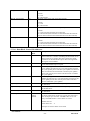
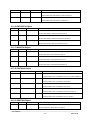
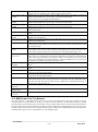
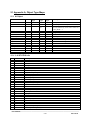
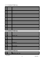
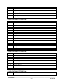
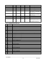
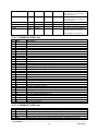
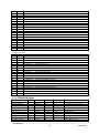
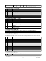
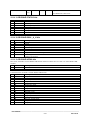
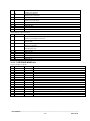
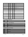
21.21.1 DRICONE STATUS bits
Bit
0
1
2
3
4
5
6
7
R/W
R
R/W
R
R/W
R
R
R/W
R/W
Description
IMPLEMENTED
ALARM_BLK
ALARM_PER_BLK
PRINT_BLK
IND1_DIST
IND2_DIST
SELECTED
AU_IND
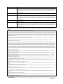
Write: 1 = Block alarm, 0 = Deblock alarm
Write: 1 = Block Printer, 0 = Deblock printer
Write 1 = Select, 0 = Deselect
Write 1 = Acknowledge alarms
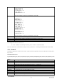
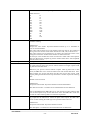
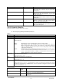
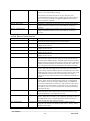
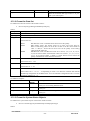
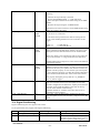
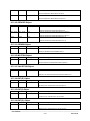
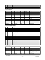
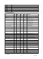
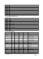
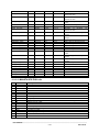
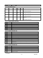
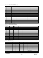
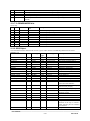
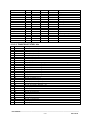
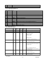
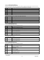
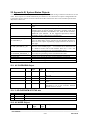
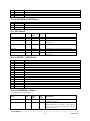
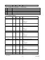
21.21.2 DRICONE BOOL_A_H bits
Bit
0
1
2
3
4
5
6
7
R/W
R
R
R
R
R
R
R
R
Description
MAN
AUTO
JOG is point of control
LOCAL is point of control
External setpoint handling
Start interlocks IBF are used
Flag to indicate if there is changes in the status word or in the limit word.
0=ACS type of Drive.
1=DCS type of Drive.
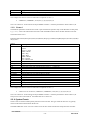
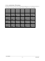
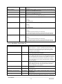
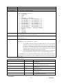
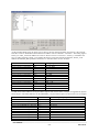
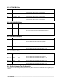
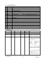
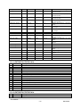
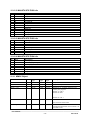
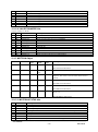
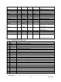
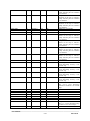
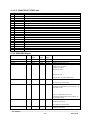
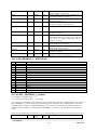
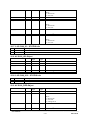
21.21.3 DRICONE INTWA bits
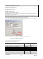
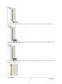
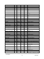
Bit 0 and 1 of INTWA in main MMCX DB-element indicates whether there is a fault or an alarm MMCX DBelement.
Bit
R/W
Description
0
R
Use fault MMCX DB-element
1
R
Use alarm MMCX DB-element
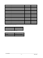
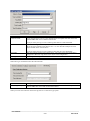
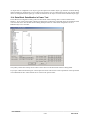
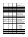
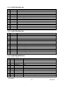
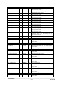
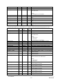
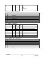
Limit Information in INTWA of fault MMCX DB-Element
Bit
R/W
Description
0
R
Torque Motor Limit
1
R
SPC Torque Min. Limit
2
R
SPC Torque Max Limit
3
R
Torque User Current Limit
4
R
Torque Inverter Current Limit
5
R
Torque Min. Limit
6
R
Torque Max Limit
7
R
Torque Reference Min. Limit
8
R
Torque Reference Max Limit
9
R
Flux Min. Limit
10
R
Frequency Min. Limit
11
R
Frequency Max Limit
12
R
DC Under Voltage Limit
13
R
DC Over Voltage Limit
14
R
Torque Limit
15
R
Frequency Limit
_________________________________________________________________________________________
User Manual
- 1662013-06-28