1
56F83xx
SCI/CAN Bootloader
User Manual
56F8300
16-bit Digital Signal Controllers
MC56F83xxBLUM
Rev. 6.0
09/2005
freescale.com
TABLE OF CONTENTS
About This Document
Audience . . . . . . . . . . . . . . . . . . . . . . . . . . . . . . . . . . . . . . . . . . . . . . . . . . . . . . . . . . . . . . . . . . vii
Organization . . . . . . . . . . . . . . . . . . . . . . . . . . . . . . . . . . . . . . . . . . . . . . . . . . . . . . . . . . . . . . . vii
•Suggested Reading . . . . . . . . . . . . . . . . . . . . . . . . . . . . . . . . . . . . . . . . . . . . . . . . . . . . . . . . . vii
•Conventions . . . . . . . . . . . . . . . . . . . . . . . . . . . . . . . . . . . . . . . . . . . . . . . . . . . . . . . . . . . . . . .viii
•Definitions, Acronyms, and Abbreviations . . . . . . . . . . . . . . . . . . . . . . . . . . . . . . . . . . . . . . . . ix
•References. . . . . . . . . . . . . . . . . . . . . . . . . . . . . . . . . . . . . . . . . . . . . . . . . . . . . . . . . . . . . . . . ix
Chapter 1
Bootloader
1.1
Bootloaders . . . . . . . . . . . . . . . . . . . . . . . . . . . . . . . . . . . . . . . . . . . . . . . . . . . . . . . . . 1-1
1.1.1
Concept. . . . . . . . . . . . . . . . . . . . . . . . . . . . . . . . . . . . . . . . . . . . . . . . . . . . . . . . . . 1-2
1.1.2
BootLoader Clock Generation. . . . . . . . . . . . . . . . . . . . . . . . . . . . . . . . . . . . . . . . . 1-2
1.1.3
Bootloader Version History . . . . . . . . . . . . . . . . . . . . . . . . . . . . . . . . . . . . . . . . . . . 1-3
1.1.4
Start-up Sequence . . . . . . . . . . . . . . . . . . . . . . . . . . . . . . . . . . . . . . . . . . . . . . . . . 1-4
1.1.5
Device Peripheral Usage . . . . . . . . . . . . . . . . . . . . . . . . . . . . . . . . . . . . . . . . . . . . 1-5
1.1.6
Files. . . . . . . . . . . . . . . . . . . . . . . . . . . . . . . . . . . . . . . . . . . . . . . . . . . . . . . . . . . . . 1-5
1.1.7
Configuration of the Bootloaders. . . . . . . . . . . . . . . . . . . . . . . . . . . . . . . . . . . . . . . 1-6
1.1.8
Error Processing . . . . . . . . . . . . . . . . . . . . . . . . . . . . . . . . . . . . . . . . . . . . . . . . . . . 1-9
1.1.9
Requirements for a User Application . . . . . . . . . . . . . . . . . . . . . . . . . . . . . . . . . . . 1-9
1.1.10
S-Record Generation . . . . . . . . . . . . . . . . . . . . . . . . . . . . . . . . . . . . . . . . . . . . . . 1-10
1.2
SCI Bootloader . . . . . . . . . . . . . . . . . . . . . . . . . . . . . . . . . . . . . . . . . . . . . . . . . . . . . . 1-10
1.2.1
Serial Terminal Programs . . . . . . . . . . . . . . . . . . . . . . . . . . . . . . . . . . . . . . . . . . . 1-11
1.2.2
56F83xxEVM Jumper Settings . . . . . . . . . . . . . . . . . . . . . . . . . . . . . . . . . . . . . . . 1-13
1.2.3
Loading an Application with the SCI Bootloader . . . . . . . . . . . . . . . . . . . . . . . . . . 1-14
1.3
CAN Bootloader . . . . . . . . . . . . . . . . . . . . . . . . . . . . . . . . . . . . . . . . . . . . . . . . . . . . . 1-15
1.3.1
CAN Bootloader Protocol . . . . . . . . . . . . . . . . . . . . . . . . . . . . . . . . . . . . . . . . . . . 1-16
1.3.2
CAN Bus Installation . . . . . . . . . . . . . . . . . . . . . . . . . . . . . . . . . . . . . . . . . . . . . . . 1-17
1.3.3
PC CAN Board . . . . . . . . . . . . . . . . . . . . . . . . . . . . . . . . . . . . . . . . . . . . . . . . . . . 1-19
1.3.4
Loading Application with CAN Bootloader . . . . . . . . . . . . . . . . . . . . . . . . . . . . . . 1-21
Chapter 2
License
2.1
Limited Use License Agreement. . . . . . . . . . . . . . . . . . . . . . . . . . . . . . . . . . . . . . . . . . 2-1
Freescale Semiconductor
Preliminary
i
Appendix A
SCI Bootloader Test Applications
A.1
LoadPDFlash Test . . . . . . . . . . . . . . . . . . . . . . . . . . . . . . . . . . . . . . . . . . . . . . . . . . . . A-1
A.1.1
Test Procedure . . . . . . . . . . . . . . . . . . . . . . . . . . . . . . . . . . . . . . . . . . . . . . . . . . . . A-1
A.2
SCI Bootloader Performance . . . . . . . . . . . . . . . . . . . . . . . . . . . . . . . . . . . . . . . . . . . . A-2
Appendix B
CAN Bootloader Test Applications
B.1
LoadPDFlash Test . . . . . . . . . . . . . . . . . . . . . . . . . . . . . . . . . . . . . . . . . . . . . . . . . . . . B-1
B.1.1
Test Procedure . . . . . . . . . . . . . . . . . . . . . . . . . . . . . . . . . . . . . . . . . . . . . . . . . . . . B-1
B.2
CAN Bootloader Performance . . . . . . . . . . . . . . . . . . . . . . . . . . . . . . . . . . . . . . . . . . . B-2
56F83xx SCI/CAN Bootloader User Manual, Rev. 6.0
ii
Freescale Semiconductor
Preliminary
LIST OF TABLES
1-1
1-2
1-3
1-4
1-5
1-6
A-1
B-1
Software Revision Description . . . . . . . . . . . . . . . . . . . . . . . . . . . . . . . . . . . . . . . . 1-3
Bootloader Configuration via User’s Application . . . . . . . . . . . . . . . . . . . . . . . . . . . 1-7
Boot Start Delay Value . . . . . . . . . . . . . . . . . . . . . . . . . . . . . . . . . . . . . . . . . . . . . . 1-8
Bootloader Configuration via Bootloader appconfig.h. . . . . . . . . . . . . . . . . . . . . . . 1-8
Error Codes for the Bootloader Applications. . . . . . . . . . . . . . . . . . . . . . . . . . . . . . 1-9
Bootloader CAN Protocol Frames Format . . . . . . . . . . . . . . . . . . . . . . . . . . . . . . 1-17
SCI Bootloader Performance. . . . . . . . . . . . . . . . . . . . . . . . . . . . . . . . . . . . . . . A-2
CAN Bootloader Performance . . . . . . . . . . . . . . . . . . . . . . . . . . . . . . . . . . . . . . B-2
Freescale Semiconductor
Preliminary
iii
56F83xx SCI/CAN Bootloader User Manual, Rev. 6.0
iv
Freescale Semiconductor
Preliminary
LIST OF FIGURES
1-1
1-2
1-3
1-4
1-5
1-6
1-7
1-8
1-9
1-10
1-11
Programming Flash on a 56F83xx Device . . . . . . . . . . . . . . . . . . . . . . . . . . . . . . . 1-2
56F83xx Boot Sequence with Bootloader . . . . . . . . . . . . . . . . . . . . . . . . . . . . . . . . 1-4
S-Record Settings in User Application’s Project Settings . . . . . . . . . . . . . . . . . . . 1-10
Loading a User’s Application via SCI . . . . . . . . . . . . . . . . . . . . . . . . . . . . . . . . . . 1-11
Loading User Code/Data via CAN Interface . . . . . . . . . . . . . . . . . . . . . . . . . . . . . 1-15
CAN Bootloader Message Flow and Protocol. . . . . . . . . . . . . . . . . . . . . . . . . . . . 1-16
Typical CAN Bus . . . . . . . . . . . . . . . . . . . . . . . . . . . . . . . . . . . . . . . . . . . . . . . . . . 1-17
CAN Termination Selected Jumper for 56F834xEVM. . . . . . . . . . . . . . . . . . . . . . 1-18
Connections Between the 56F83xxEVM (Jumper J5/J12) and PC Host . . . . . . . 1-19
Location of NI-CAN Software . . . . . . . . . . . . . . . . . . . . . . . . . . . . . . . . . . . . . . . . 1-20
NI-CAN Software Configuration . . . . . . . . . . . . . . . . . . . . . . . . . . . . . . . . . . . . . . 1-21
Freescale Semiconductor
Preliminary
v
56F83xx SCI/CAN Bootloader User Manual, Rev. 6.0
vi
Freescale Semiconductor
Preliminary
About This Document
This manual describes the 56F83xx SCI/CAN Bootloaders application.
The Bootloaders application was not designed for the 56F81xx devices. The 56F83xx
Bootloaders application does, however, fully support 56F81xx software development.
Audience
This manual targets software developers utlizing the 56F83xx Bootloaders applications.
Organization
This User’s Manual consists of the following sections:
•
Chapter 1, Bootloader -- describes the serial and CAN Bootloaders applications provided with the
FlexCAN driver
•
Chapter 2, License -- provides the license required to use this product
•
Appendix A -- describes the tests and performance of the SCI Bootloader
•
Appendix B -- describes the tests and performance of the CAN Bootloader
Suggested Reading
We recommend that you have a copy of the following references:
•
DSP56800E Reference Manual, Freescale, DSP56800ERM
•
56F8300 Peripheral User Manual, Freescale, MC56F8300UM
•
Inside CodeWarrior: Core Tools, Metrowerks Corp.
•
NI-CAN User Manual, National Instruments
Preface, Rev. 6.0
Freescale Semiconductor
Preliminary
vii
Conventions
This document uses the following notational conventions:
Typeface,
Symbol or Term
Meaning
Examples
Courier
Monospaced
Type
Code examples
//Process command for line flash
Italic
Directory names,
project names,
calls,
functions,
statements,
procedures,
routines,
arguments,
file names,
applications,
variables,
directives,
code snippets
in text
...and contains these core directories:
applications contains applications software...
...CodeWarrior project, 3des.mcp is...
...the pConfig argument....
...defined in the C header file, aec.h....
Reference sources,
paths,
emphasis
...refer to the Targeting DSP56F80x Platform manual....
Blue Text
Linkable on-line
...refer to Chapter 7, License....
Number
Any number is considered a positive value,
unless preceded by a
minus symbol to signify
a negative value
3V
ALL CAPITAL
LETTERS
# defines/
defined constants
# define INCLUDE_STACK_CHECK
Brackets [...]
Function keys
...by pressing function key [F7]
Quotation
marks, “...”
Returned messages
...the message, “Test Passed” is displayed....
Bold
...see: C:\Program Files\freescale\help\tutorials
-10
DES-1
...if unsuccessful for any reason, it will return “NULL”...
56F83xx SCI/CAN Bootloader User Manual, Rev. 6.0
viii
Freescale Semiconductor
Preliminary
Definitions, Acronyms, and Abbreviations
The following list defines the acronyms and abbreviations used in this document. As this
template develops, this list will be generated from the document. As we develop more group
resources, these acronyms will be easily defined from a common acronym dictionary. Please note
that while the acronyms are in solid caps, terms in the definition should be initial capped ONLY
IF they are trademarked names or proper nouns.
CAN
Controller Area Network
CAN ID
CAN Identifier
IDE
Identifier Extension
FlexCAN
Flexible Controller Area Network
RAM
Random Access (read/write) Memory
References
The following sources were used to produce this book:
1. DSP56800E Reference Manual, Freescale, DSP56800ERM/D
2. CAN Specifications, Version 2.0, 1991, Robert Bosch GmbH
3. NI-CAN User Manual, National Instruments
Preface, Rev. 6.0
Freescale Semiconductor
Preliminary
ix
56F83xx SCI/CAN Bootloader User Manual, Rev. 6.0
x
Freescale Semiconductor
Preliminary
Bootloaders
Chapter 1
Bootloader
1.1 Bootloaders
Note: CAN applications are NOT supported on 56F81xx devices
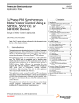
The Bootloaders for the 56F83xx devices were developed to load and run a user’s application by
parsing an S-Record file, then copying the parsed S-Record file into the appropriate Program and
Data memory. Figure 1-1 illustrates the S-Record flow.
The Bootloader supports two communication methods:
•
•
via SCI peripheral
via CAN bus peripheral
The Bootloader can be used for the following 56F83xx part numbers:
•
•
•
•
56F832x devices
— MC56F8322
— MC56F8323
56F834x devices:
— MC56F8345
— MC56F8346
— MC56F8347
56F835x devices:
— MC56F8355
— MC56F8356
— MC56F8357
56F836x devices:
— MC56F8365
— MC56F8366
— MC56F8367
Bootloader, Rev. 6.0
Freescale Semiconductor
Preliminary
1-1
Bootloaders
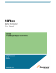
1.1.1 Concept
Program Flash
Data Flash
S-Record
Bootloader
Running
SCI/
CAN
S-Record
Figure 1-1. Programming Flash on a 56F83xx Device
The Bootloaders are located in a dedicated Program Memory region of the 56F83xx device,
called Boot Flash. The Bootloaders application first performs a mass erase of the entire program
Flash and then reads the S-Record file of the user’s application (generated by CodeWarrior, for
example) via an SCI or CAN interface. It then parses the S-Record lines and stores code and data
in Program and Data Flash memory.
When the processing of the S-Record file is finished, the Bootloaders launch the loaded
application. If an error occurs during the loading of the S-Record file, the Bootloader outputs an
error message with an error number via the serial connection and waits for a processor reset.
1.1.2 BootLoader Clock Generation
The 56F834x, 56F835x, and 56F836x Bootloaders use an off-chip crystal to generate the clock
for the processor. A 56F832x Bootloader can use either its internal relaxation oscillator or an
off-chip crystal for processor clock generation. In all cases, the Bootloader determines how the
clock is generated and makes the necessary adjustments.
56F83xx SCI/CAN Bootloader User Manual, Rev. 6.0
1-2
Freescale Semiconductor
Preliminary
Bootloaders
1.1.3 Bootloader Version History
Table 1-1. Software Revision Description
Version Number
Description
1.0.0
• Did not write entire trim register value for 832x on-chip oscillator
( See FAQ #21234)
• Wrote FMCLKD register independent of Flash programming which
prevents user application from writing. This bug only affects customers
that need to program Flash at run-time with system clock rates outside of
the range of 38.4 to 51.2MHz.
• COP reset vector programmed incorrectly preventing application use
• See FAQ #25093
• Cleaned up code and documentation
• Fixed 832x trim value
• Added support for 835x
• First attempt to correct FMCLKD bug, which failed
• Fixed FMCLKD bug
• Fixed COP reset vector to jump to Bootloader start
• Added support for 836x
• See FAQ #21042 for code and documentation
1.0.1
1.0.2
1.0.3
Bootloader, Rev. 6.0
Freescale Semiconductor
Preliminary
1-3
Bootloaders
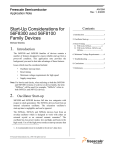
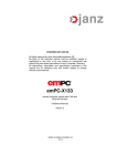
1.1.4 Start-up Sequence
Figure 1-2 illustrates the Start-up Sequence with the Bootloaders.
Program Flash Memory
0x0000
JSR
0x0001
ArchStart()
2
.pInterruptVector
bootArchStart()
{
...
0xA2 - End Prog
Application Code
/*Start User Application*/
...
}
Boot Flash Memory
1
Power-up/Reset
Bootloader code
.pbootInterruptVector
0x20000
JSR
0x20001
bootArchStart()
0x20002
JSR
0x20003
Interrupt1()
0x20004
Rev Number
0x20005
CheckSum
0x20006
CheckSum
0x20007
0000
0x20008
Rest of Vector Table
and Boot Code
3
archStart()
{
...
}
ApplicationCode
0x20009
1.
Power-up/Reset -- The hardware reset vector identifies the address that the processor accesses
when it recognizes a power-up or power reset. When the 56F83xx Bootloader is present, the
Bootloader Code is executed first.
2.
Bootloading Process -- When the 56F83xx Bootloader completes its execution, it transfers
control to the Application Code by performing a JMP instruction to an address specified in the
corresponding S-record file (default 0x0000).
3.
Jump to the User Application Code -- The Application Code entry point is called by the JMP
instruction from the 0x0000 address.
Figure 1-2. 56F83xx Boot Sequence with Bootloader
56F83xx SCI/CAN Bootloader User Manual, Rev. 6.0
1-4
Freescale Semiconductor
Preliminary
Bootloaders
1.1.5 Device Peripheral Usage
The Bootloaders are used with the 56F83xx device configured in MODE 0 (MA = 0).
The Bootloaders use only internal Data RAM from 0x0000 to 0x0FFF and internal Program
RAM for data buffering.
The Bootloaders initialize only the following 56F83xx device peripherals:
•
SCI 0 for 56F836x devices
•
SCI 0 for 56F835x devices
•
SCI 0 for 56F834x devices
•
SCI 1 for 56F832x devices
•
•
•
CAN
Timer A
PLL initialization
Each peripheral is set to its default state when loading is complete.
1.1.6 Files
The Bootloader applications for the 56F836x, 56F835x, 56F834x and 56F832x targets are found
in the following directory locations:
•
•
If installed from FAQ zip file:
— CAN version of Bootloader:
..\bootloader\can\
— SCI version of Bootloader:
..\bootloader\sci\
If generated from Processor Expert Examples Stationery:
— All files will be located in the project folder specified by the user.
Each version of the Bootloaders’ software includes the following files:
•
•
•
Project file:
— bootloader.mcp
Main program:
— bootloader.c
Header file with common parameters:
— bootloader.h
Bootloader, Rev. 6.0
Freescale Semiconductor
Preliminary
1-5
Bootloaders
•
•
•
•
Support file, appconfig.c:
— ..\appconfig\appconfig.c
Support file, appconfig.h:
— ..\appconfig\appconfig.h
Linker Command files:
— ..\appconfig\56F836x_boot_flash_linker.cmd
— ..\appconfig\56F835x_boot_flash_linker.cmd
— ..\appconfig\56F834x_boot_flash_linker.cmd
— ..\appconfig\56F832x_boot_flash_linker.cmd
Flash configuration files:
— ..\appconfig\56F836x_flash.cfg
— ..\appconfig\56F835x_flash.cfg
— ..\appconfig\56F834x_flash.cfg
— ..\appconfig\56F832x_flash.cfg
1.1.6.1 Building and Loading the Bootloader
•
•
To build and link a Bootloader application:
— Open the bootloader.mcp project file for either the SCI or CAN Bootloader in the CodeWarrior
IDE
— Select the 56F836x, 56F835x, 56F834x or 56F832x target
— Execute the Project/Make command
To build and download this application:
— Open the bootloader.mcp project file for either the SCI or CAN Bootloader in the CodeWarrior
IDE
— Select the 56F836x, 56F835x, 56F834x or 56F832x target
— Execute the Project/Debug command
1.1.7 Configuration of the Bootloaders
The Bootloaders can be configured in two ways:
•
•
User’s application - The user’s application can modify certain Data Flash Addresses at run-time
to modify the configuration of the Bootloaders. These are described in more detail in Section
1.1.7.1.
Modifying the Bootloader application’s appconfig.h file - The appconfig.h file for the
Bootloaders’ project can be modified to change the Bootloader’s configuration before burning the
Bootloader into the 56F83xx device’s Flash. This is described in more detail in Section 1.1.7.2.
56F83xx SCI/CAN Bootloader User Manual, Rev. 6.0
1-6
Freescale Semiconductor
Preliminary
Bootloaders
1.1.7.1 User’s Application Bootloader Configuration
The Bootloaders allow a user’s application to configure certain parameters within the Bootloader
during the run-time of the user’s application. They are described in Table 1-2.
Note:
The last 3 cells in the Data Flash memory are reserved for Bootloader configuration.
Table 1-2. Bootloader Configuration via User’s Application
Parameter
Data Flash
Address
Default Setting
Description
BOOT_START_DELAY
0x1FFD
(low byte)
#define
BOOT_START_DELAY 30
This macro defines the Bootloader inactivity
interval in seconds, after which time the
Bootloader passes control to the user’s
application. See Table 1-2.
BOOT_VERSION_PROMPT
0x1FFD
(high byte)
#define
BOOT_VERSION_PROMPT
0xFF
This macro defines whether the Bootloader
displays a version prompt after reset. To turn
off the version prompt, #define
BOOT_VERSION_PROMPT to 0x00.
Note:
The setting of Bootloader configuration parameters by an application is optional,
except BOOT_START_DELAY. This parameter must be defined by the user’s
application.
Note:
Data Flash locations 0x1FFE and 0x1FFF are used by the Bootloader to store the
starting address of the user application.
The following example illustrates how a user configures his application to modify the delay start
time to 20 seconds from the default of 30 seconds. Upon a power-on reset, the Bootloader
application reads the BOOT_START_DELAY and BOOT_VERSION_PROMPT values and
behaves according to Table 1-3.
The user’s application linker.cmd file must contain the following:
...
.xBootCfg
(R)
: ORIGIN = 0x1FFD,
...
FORCE_ACTIVE {FCfg_StartDelay}
...
.ApplicationConfiguration :
{
* (appconst.data)
} > .xBootCfg
...
Note:
LENGTH = 0x0003
A user must define .xFlash within the linker.cmd file so there is no overlap with the
previously described .xBootCfg.
Bootloader, Rev. 6.0
Freescale Semiconductor
Preliminary
1-7
Bootloaders
The user’s application code must contain the following:
#define BOOT_START_DELAY 20
#define BOOT_VERSION_PROMPT 0xFF
#pragma define_section bootcfg_section "appconst.data" R
#pragma section bootcfg_section begin
const unsigned short Cfg_StartDelay = (BOOT_VERSION_PROMPT << 8) |
BOOT_START_DELAY;
#pragma section bootcfg_section end
Note:
A user’s application could easily incorporate a function that could change the current
delay time dynamically by writing a value to 0x1FFD.
Table 1-3. Boot Start Delay Value
BOOT_START_DELAY
0
1-254
255
Result
Jumps immediately to the application's Start Address
Waits a specified number of seconds before the S-Record begins to download.
If a message is not received before the delay time has expired, the Bootloader
jumps to the application's Start Address.
Waits forever before the S-Record begins downloading
1.1.7.2 Bootloader Appconfig.h Configuration
The Bootloaders have certain parameters that can be set and configured from their default values
by modifying the Bootloader application’s appconfig.h file. These parameters are described in
Table 1-4.
Table 1-4. Bootloader Configuration via Bootloader appconfig.h
Parameter
Default Setting
Description
BOOT_SCI_BAUD_RATE
#define
BOOT_SCI_BAUD_RATE
115200 bps
Sets the SCI baud rate
NOTE: Maximum rate is
115200 bps
SCI
USE_HYPERTERMINAL
None
#undef
USE_HYPERTERMINAL
A user should define this
parameter when using a
hyperterminal program
other than the srecload
utility provided with the
Bootloader software.
Note:
Bootloader
The CAN Bootloader uses extended IDs associated with the CAN 2.0B spec. This is
explained in detail in the NI-CAN User Manual.
56F83xx SCI/CAN Bootloader User Manual, Rev. 6.0
1-8
Freescale Semiconductor
Preliminary
Bootloaders
1.1.8 Error Processing
Table 1-5 describes possible error messages receieved when utilizing the Bootloaders.
Table 1-5. Error Codes for the Bootloader Applications
Error
Code
Error Title
Possible Reasons
What to Do
02
Invalid Character
The character received is not “S”
or any hexadecimal digit
• Verify that S-Record file does not
contain any inaccurate characters
• Check connections and send mode in
terminal program
03
Invalid S-Record
Format
• Invalid record type; permitted
types are 0,3,7
• The S-Record length is less
than the address plus
checksum length
• Verify S-Record file
04
Wrong S-Record
Checksum
The checksum calculated around
the S-Record received did not
match the one received
• Check the S-Record file
• Check connections and send mode in
terminal program
06
Flash
Programming Error
After programming a word into
Flash, the programmed word read
back is not equal to the expected
value
• The Bootloader tries to program Flash
only once and performs a read back /
verification of the value
0C
CAN Error
CAN communication error
• Check the CAN connections and try to
repeat download
0D
Low Voltage
Interrupt
Low Voltage Interrupt occurred
• Check power and try to repeat
download
1.1.9 Requirements for a User Application
The following restrictions apply if an application is loaded via the Bootloader:
•
•
•
An application cannot place code into the Boot Flash memory area of the 56F83xx device
Initialized variables from an application cannot be placed into internal Data RAM or into internal
Program RAM while loading; therefore, the user’s application is responsible for initializing data
after loading is complete
The user’s application must fit within Program and Data Flash of the 56F83xx device
Bootloader, Rev. 6.0
Freescale Semiconductor
Preliminary
1-9
SCI Bootloader
1.1.10 S-Record Generation
Figure 1-3 illustrates how a user’s application can set up CodeWarrior to generate an S-Record
needed by the Bootloaders to program the user’s application into the 56F83xx device’s Flash.
Figure 1-3. S-Record Settings in User Application’s Project Settings
Note:
“Max Record Length” and “EOL Character” are set to the default values shown in
Figure 1-3. “Max Record Length” can be modified to up to 252. “EOL Character” can
be changed to “Mac” or “UNIX” with no effect.
1.2 SCI Bootloader
The SCI Bootloader supports loading a user application presented as an S-record file via SCI by
using a standard serial terminal program on a host PC; see Figure 1-4.
56F83xx SCI/CAN Bootloader User Manual, Rev. 6.0
1-10
Freescale Semiconductor
Preliminary
SCI Bootloader
56F83xxEVM
S-Record
RS-232
Figure 1-4. Loading a User’s Application via SCI
1.2.1 Serial Terminal Programs
Most serial terminal programs can be used to download an S-Record file from a host to an
56F83xx device via the SCI Bootloader.
A PC Serial Host Loader utility has been developed for both the SCI and CAN Bootloaders. This
utility is optimized to speed up the download time of the user’s application S-Record. SCI
options and use are described in Section 1.2.1.2.
1.2.1.1 Host Serial Terminal Program Configuration
A Host Serial Terminal program must be configured as follows:
Baud rate
8N1
Flow Control
Protocol
115200 bps
8 data bits, no parity, 1 stop bit character format
Xon/Xoff
Bootloader, Rev. 6.0
Freescale Semiconductor
Preliminary
1-11
SCI Bootloader
1.2.1.2 PC Host Loader Utility - SCI
The utility can be found at the following location,
•
•
If installed from FAQ:
x86\win32\applications\srec\srecLoad.exe
If installed with CodeWarrior:
<CodeWarrior_Installation_Directory>\ProcessorExpert\Tools\applications\srec\sRecLoad.exe
SCI options for the command-line PC Host Loader utility include:
-i:<Interface>
-s:<S-Record file>
-l:<logfile>
-b:<baudrate>
The COM port used for download - (COM1, COM2)
The name of the S-Record file to download
The name of the log file to log utility operations
The baud rate value for SCI (RS-232)
Default = 115200bps
The following example shows how to use the utility with the SCI Bootloader:
srecLoad -i:COM1 -s:56F8346_flash.elf.S -b:115200 -l:log.txt
1.2.1.3 PC Host Loader Utility - CAN
The utility can be found at the following location,
•
•
If installed from FAQ:
x86\win32\applications\srec\srecLoad.exe
If installed with CodeWarrior:
<CodeWarrior_Installation_Directory>\ProcessorExpert\Tools\applications\srec\sRecLoad.exe
SCI options for the command-line PC Host Loader utility include:
-i:<Interface>
-s:<S-Record file>
-l:<logfile>
-b:<baudrate>
-r:<CAN ID>
-a:<CAN ID>
The CAN device name used for download (CAN0, CAN1)
The name of the S-Record file to download
The name of the log file to log utility operations
The baud rate value defines SCI or CAN speed to
communicate with the Bootloader in bits per second (bps)
Default = 500000bps
The host request CAN ID to transmit S-record
Default = 20000001
Bootloader reply (acknowledgement) CAN ID
Default = 20000002
56F83xx SCI/CAN Bootloader User Manual, Rev. 6.0
1-12
Freescale Semiconductor
Preliminary
SCI Bootloader
The following example shows how to use the utility with the CAN Bootloader:
srecLoad -i:CAN1 -s:56F8346_flash.elf.S -b:500000 -r:20000001 -a:20000002
1.2.2 56F83xxEVM Jumper Settings
1.2.2.1 56F835xEVM or 56F836xEVM Jumper Settings
To load the Bootloader into the 56F835xEVM or 56F836xEVM device, the following jumper
settings are needed:
•
•
•
Set Jumper JG4 - “Int BOOT”, (EXTBOOT pin on chip)
Do not connect Jumper JG10 - “RS-232 Disable”
Do not connect Jumper JG3 - “CC Disable”
To start a previously loaded Bootloader on the 56F835xEVM or 56F836xEVM board while the
parallel cable is connected to the EVM board, the following jumper settings are needed:
•
•
•
Set Jumper JG4 - “Int BOOT”, (EXTBOOT pin on chip)
Do not connect Jumper JG10 - “RS-232 Disable”
Do not connect Jumper JG3 - “CC Disable”
To start a previously loaded Bootloader on the 56F835xEVM or 56F836xEVM board while the
parallel cable is not connected to the EVM board, use these jumper settings:
•
•
•
Note:
Set Jumper JG4 - “Int BOOT”, (EXTBOOT pin on chip)
Do not connect JumperJG10 - “RS-232 Disable”
Set Jumper JG3 - “CC Disable”
All other 56F835xEVM jumper settings should be set to default values.
1.2.2.2 56F834xEVM Jumper Settings
To load the Bootloader into the 56F834xEVM device, the following jumper settings are needed:
•
•
•
Set Jumper JG3 - “Int BOOT”, (EXTBOOT pin on chip)
Do not connect Jumper JG7 - “RS-232 Disable”
Do not connect Jumper JG9 - “CC Disable”
To start a previously loaded Bootloader on the 56F834xEVM board while the parallel cable is
connected to the EVM board, the following jumper settings are needed:
Bootloader, Rev. 6.0
Freescale Semiconductor
Preliminary
1-13
SCI Bootloader
•
•
•
Set Jumper JG3 - “Int BOOT”, (EXTBOOT pin on chip)
Do not connect Jumper JG7 - “RS-232 Disable”
Do not connect Jumper JG9 - “CC Disable”
To start a previously loaded Bootloader on the 56F834xEVM board while the parallel cable is
not connected to the EVM board, use these jumper settings:
•
•
•
Note:
Set Jumper JG3 - “Int BOOT”, (EXTBOOT pin on chip)
Do not connect JumperJG7 - “RS-232 Disable”
Set Jumper JG9 - “CC Disable”
All other 56F834xEVM jumper settings should be set to default values.
1.2.2.3 56F832xEVM Jumper Settings
To load the Bootloader into the 56F832xEVM device, the following jumper settings are needed:
•
•
Do not connect Jumper JG4 - “RS-232 Disable”
Do not connect Jumper JG3 - “CC Disable”
To start a previously loaded Bootloader on the 56F832xEVM board while the parallel cable is
connected to the EVM board, the following jumper settings are needed:
•
•
Do not connect Jumper JG4 - “RS-232 Disable”
Do not connect Jumper JG3 - “CC Disable”
To start a previously loaded Bootloader on the 56F832xEVM board while the parallel cable is
not connected to the EVM board, use these jumper settings:
•
•
Do not connect JumperJG4 - “RS-232 Disable”
Set Jumper JG3 - “CC Disable”
All other 56F832xEVM jumper settings should be set to default values.
1.2.3 Loading an Application with the SCI Bootloader
•
•
•
•
Set jumpers as described in Section 1.2.2
Connect a parallel cable from the Host to the 56F83xxEVM (P1)
Connect a serial cable from the Host to the 56F83xxEVM (P2)
Apply power to the 56F83xxEVM (P3)
56F83xx SCI/CAN Bootloader User Manual, Rev. 6.0
1-14
Freescale Semiconductor
Preliminary
CAN Bootloader
•
•
•
Build and load the SCI Bootloader into Flash as described in Section 1.1.6.1
Press the RESET button (S1) on the 56F83xxEVM
Use the PC Host Loader utility as described in Section 1.2.1.2
If loading is successful, something similar to the following is displayed in the command window:
(c) 2003 MOTOROLA. S-Record loader for the MC56F83xx. ver. 1.0.1
Waiting for application
S-Record.............................................................................
.....................................................................................
.....................................................................................
........
Loaded 0x021FCC
bytes.
Application started from address 0x015D
If any error is detected while loading the S-Record file, the Bootloader displays an error message;
see Table 1-5 for a detailed list of error messages. For example, if an S-record file contains a
character that is not permitted for S-Records, the following message is displayed:
“Error # 02”
After an error message is displayed, the Bootloader waits for a processor reset.
1.3 CAN Bootloader
Note: The CAN Bootloader is NOT available on 56F81xx devices.
The CAN Bootloader allows a user to load his application via an S-Record and CAN interface;
see Figure 1-5.
CAN Connector
CAN Bus
CAN Card
56F83xxEVM
Figure 1-5. Loading User Code/Data via CAN Interface
Bootloader, Rev. 6.0
Freescale Semiconductor
Preliminary
1-15
CAN Bootloader
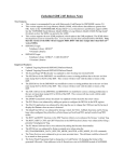
1.3.1 CAN Bootloader Protocol
The CAN Bootloader supports the loading of a user’s application via the CAN bus. A PC Host
Loader utility sends an S-Record image file through a CAN bus in accordance with the CAN
Bootloader protocol.
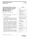
The entire S-Record image file may contain several S-Records. Each S-Record is transmitted
according to the protocol presented in Table 1-6 and Figure 1-6.
The CAN Bootloader protocol is based on two frames:
S-Record Segment frames contain at least 8 bytes of the loaded S-Record
Acknowledgement frames contain the target S-Record counter and the error field
1st fram
e(s-rec
ord[1:8
])
Frame
Time
2nd fra
me(s-r
ecord[1
Buffering
:8])
Buffering
last fra
m
Frame
Time
S-Record Session
Frame
Time
•
•
e(s-rec
o
rd[1:8])
Flash Programming
cord co
ack(s-re
Bootloader Host Side
u
)
o r co d e
nter, err
Acknowledgement
Time
Bootloader Target Side
Figure 1-6. CAN Bootloader Message Flow and Protocol
56F83xx SCI/CAN Bootloader User Manual, Rev. 6.0
1-16
Freescale Semiconductor
Preliminary
CAN Bootloader
Table 1-6. Bootloader CAN Protocol Frames Format
CAN Frame
S-Record
Segment
Last S-Record
Segment
Data Reply
CAN ID
CAN_ID_CODE
CAN_ID_CODE
CAN_ID_REPLY
Length
8
1:8
6
Data 0
Data 1
S-Record
Counter1
Data 2
Data 3
S-Record
Data 4
S-Record
Error Code
Data 5
Data 6
Data 7
1.
The Bootloader version is located in the acknowledgement frame in
response to the first S-Record line; the application’s Start Address is
located in the acknowledgement frame in response to the last
S-Record line.
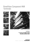
1.3.2 CAN Bus Installation
The simplest CAN bus is two wires terminated by 124 ohm resistors, as shown in Figure 1-7.
The 56F83xxEVM board contains a CAN terminator resistor that can be enabled/disabled via a
jumper; see Figure 1-8.
CAN High
124 ohm
124 ohm
CAN Low
CANH
CANL
EVM1
CANH
CANL
EVM2
CANH
CANL
EVM3
Figure 1-7. Typical CAN Bus
Bootloader, Rev. 6.0
Freescale Semiconductor
Preliminary
1-17
CAN Bootloader
JG11
Figure 1-8. CAN Termination Selected Jumper for 56F834xEVM
To enable the CAN termination, place a jumper on:
•
•
•
JG13 for the 56F835xEVM and 56F836xEVM
JG11 for the 56F834xEVM
JG10 for the 56F832xEVM
Removing the jumper (NC) disables the CAN termination.
56F83xx SCI/CAN Bootloader User Manual, Rev. 6.0
1-18
Freescale Semiconductor
Preliminary
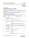
CAN Bootloader
No Connection
Shield
3 4
5
V --
CAN_L
No Connection
CANH
7
8 9
CAN_H
No Connection
V+
6
Optional Ground (V --)
1 2
J5 - 56F834xEVM
J12 - 56F832xEVM
J20 - 56F835xEVM
J20 - 56F836xEVM
SHIELD
CANL
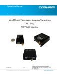
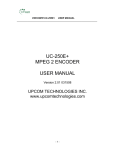
Figure 1-9. Connections Between the 56F83xxEVM (Jumper J5/J12) and PC Host
•
•
•
Connect Pin 3, CANL, on the 56F83xxEVM to CANL, Pin 2, on the PC CAN card
Connect Pin 4, CANH, on the 56F83xxEVM to CANH, Pin 7, on the PC CAN card
Connect Pin 5, GND, on the 56F83xxEVM to Shield, Pin 5, on the PC CAN card
1.3.3 PC CAN Board
The CAN PC Host application uses National Instruments’ PCI-CAN/2 board. The software
drivers shipped with the board are labeled as: “National Instruments NI-CAN Software for
Windows 2000/NT/XP/Me/9x and LabVIEW Real-Time (RT) Version 1.6”.
Bootloader, Rev. 6.0
Freescale Semiconductor
Preliminary
1-19
CAN Bootloader
1.3.3.1 Location of NI-CAN Configuration Software
Figure 1-10 illustrates the location of the NI-CAN software.
Figure 1-10. Location of NI-CAN Software
56F83xx SCI/CAN Bootloader User Manual, Rev. 6.0
1-20
Freescale Semiconductor
Preliminary
CAN Bootloader
1.3.3.2 NI-CAN Software Configuration
Figure 1-11 illustrates what a user would see after the NI-CAN driver software has been
successfully installed. Please refer to National Instruments’ NI-CAN Software documentation for
more details on configuring the driver software.
Figure 1-11. NI-CAN Software Configuration
1.3.4 Loading Application with CAN Bootloader
•
•
•
•
•
•
•
•
Configure NI-CAN software as described in Section 1.3.3
Set jumpers as described in Section 1.2.2
Connect a parallel cable from the Host to the 56F83xxEVM (P1)
Connect the CAN bus as shown in Figure 1-9
Apply power to the 56F83xxEVM (P3)
Build and load the CAN Bootloader into Flash as described in Section 1.1.6.1
Push the RESET button (S1) on the 56F83xxEVM board
Use the PC Host Loader utility as described in Section 1.2.1.3
Bootloader, Rev. 6.0
Freescale Semiconductor
Preliminary
1-21
CAN Bootloader
If loading is successful, something similar to the following is displayed in the command window:
(c) 2003 MOTOROLA. S-Record loader for the MC56F83xx. ver. 1.0.1
Waiting for application
S-Record.............................................................................
.....................................................................................
.....................................................................................
........
Loaded 0x021FCC
bytes.
Application started from address 0x015D
If any error is detected while loading the S-Record file, the Bootloader displays an error message;
see Table 1-5 for a list of error codes. For example, if an S-record file contains a character that is
not permitted for S-Records, the following message is displayed:
“Error # 02”
After an error message is displayed, the Bootloader waits for a processor reset.
56F83xx SCI/CAN Bootloader User Manual, Rev. 6.0
1-22
Freescale Semiconductor
Preliminary
Limited Use License Agreement
Chapter 2
License
2.1 Limited Use License Agreement
LIMITED USE LICENSE AGREEMENT
PLEASE READ THIS AGREEMENT CAREFULLY BEFORE USING THIS SOFTWARE.
BY USING OR COPYING THE SOFTWARE, YOU AGREE TO THE TERMS OF THIS
AGREEMENT.
The software in either source code form ("Source") or object code form ("Object") (cumulatively
hereinafter "Software") is provided under a license agreement ("Agreement") as described herein.
Any use of the Software including copying, modifying, or installing the Software so that it is
usable by or accessible by a central processing unit constitutes acceptance of the terms of the
Agreement by the person or persons making such use or, if employed, the employer thereof
("Licensee") and if employed, the person(s) making such use hereby warrants that they have the
authority of their employer to enter this license agreement. If Licensee does not agree with and
accept the terms of this Agreement, Licensee must return or destroy any media containing the
Software or materials related thereto, and destroy all copies of the Software.
The Software is licensed to Licensee by Freescale Semiconductor Inc. ("Freescale") for use under
the terms of this Agreement. Freescale retains ownership of the Software. Freescale grants only
the rights specifically granted in this Agreement and grants no other rights. Title to the Software,
all copies thereof and all rights therein, including all rights in any intellectual property including
patents, copyrights, and trade secrets applicable thereto, shall remain vested in Freescale.
For the Source, Freescale grants Licensee a personal, non-exclusive, non-assignable, revocable,
royalty-free right to use, copy, and make derivatives of the Source solely in a development
system environment in order to produce object code solely for operating on a Freescale
semiconductor device having a central processing unit ("Derivative Object").
For the Object and Derivative Object, Freescale grants Licensee a personal, non-exclusive,
non-assignable, revocable, royalty-free right to copy, use, and distribute the Object and the
Derivative Object solely for operating on a Freescale semiconductor device having a central
processing unit.
Licensee agrees to: (a) not use, modify, or copy the Software except as expressly provided herein,
(b) not distribute, disclose, transfer, sell, assign, rent, lease, or otherwise make available the
License, Rev. 6.0
Freescale Semiconductor
Preliminary
2-1
Limited Use License Agreement
Software, any derivatives thereof, or this license to a third party except as expressly provided
herein, (c) not remove obliterate, or otherwise defeat any copyright, trademark, patent or
proprietary notices, related to the Software (d) not in any form export, re-export, resell, ship or
divert or cause to be exported, re-exported, resold, shipped, or diverted, directly or indirectly, the
Software or a direct product thereof to any country which the United States government or any
agency thereof at the time of export or re-export requires an export license or other government
approval without first obtaining such license or approval.
THE SOFTWARE IS PROVIDED ON AN "AS IS" BASIS AND WITHOUT WARRANTY OF
ANY KIND INCLUDING (WITHOUT LIMITATION) ANY WARRANTIES OF
MERCHANTABILITY OR FITNESS FOR A PARTICULAR PURPOSE. IN NO EVENT
SHALL FREESCALE BE LIABLE FOR ANY LIABILITY OR DAMAGES OF ANY KIND
INCLUDING, WITHOUT LIMITATION, DIRECT OR INDIRECT OR INCIDENTAL OR
CONSEQUENTIAL OR PUNITIVE DAMAGES OR LOST PROFITS OR LOSS OF USE
ARISING FROM USE OF THE SOFTWARE OR THE PRODUCT REGARDLESS OF THE
FORM OF ACTION OR THEORY OF LIABILITY (INCLUDING WITHOUT LIMITATION,
ACTION IN CONTRACT, NEGLIGENCE, OR PRODUCT LIABILITY) EVEN IF
FREESCALE HAS BEEN ADVISED OF THE POSSIBILITY OF SUCH DAMAGE. THIS
DISCLAIMER OF WARRANTY EXTENDS TO LICENSEE OR USERS OF PRODUCTS
AND IS IN LIEU OF ALL WARRANTIES WHETHER EXPRESS, IMPLIED, OR
STATUTORY, INCLUDING IMPLIED WARRANTIES OF MERCHANTABILITY OR
FITNESS FOR PARTICULAR PURPOSE.
Freescale does not represent or warrant that the Software is free of infringement of any third party
patents, copyrights, trade secrets, or other intellectual property rights or that Freescale has the
right to grant the licenses contained herein. Freescale does not represent or warrant that the
Software is free of defect, or that it meets any particular requirements or need of the Licensee, or
that it conforms to any documentation, or that it meets any standards.
Freescale shall not be responsible to maintain the Software, provide upgrades to the Software, or
provide any field service of the Software. Freescale reserves the right to make changes to the
Software without further notice to Licensee.
The Software is not designed, intended, or authorized for use as components in systems intended
for surgical implant into the body, or other applications intended to support or sustain life, or for
any other application in which the failure of the Software could create a situation where personal
injury or death may occur. Should Licensee purchase or use the Software for any such
unintended or unauthorized application, Licensee shall indemnify and hold Freescale and its
officers, employees, subsidiaries, affiliates, and distributors harmless against all claims, costs,
damages, and expenses, and reasonable attorney fees arising out of, directly or indirectly, any
56F83xx SCI/CAN Bootloader User Manual, Rev. 6.0
2-2
Freescale Semiconductor
Preliminary
Limited Use License Agreement
claim of personal injury or death associated with such unintended or unauthorized use, even if
such claim alleges that Freescale was negligent regarding the design or manufacture of the
Software.
The term of this Agreement is for as long as Licensee uses the Software for its intended purpose
and is not in default of any provisions of this Agreement. Freescale may terminate this
Agreement if Licensee is in default of any of the terms and conditions of this Agreement.
This Agreement shall be governed by and construed in accordance with the laws of the State of
Arizona and can only be modified in a writing signed by both parties. Licensee agrees to
jurisdiction and venue in the State of Arizona.
By using, modifying, installing, compiling, or copying the Software, Licensee acknowledges that
this Agreement has been read and understood and agrees to be bound by its terms and conditions.
Licensee agrees that this Agreement is the complete and exclusive statement of the agreement
between Licensee and Freescale and supersedes any earlier proposal or prior arrangement,
whether oral or written, and any other communications relative to the subject matter of this
Agreement.
License, Rev. 6.0
Freescale Semiconductor
Preliminary
2-3
Limited Use License Agreement
56F83xx SCI/CAN Bootloader User Manual, Rev. 6.0
2-4
Freescale Semiconductor
Preliminary
Appendix A
SCI Bootloader Test Applications
A.1 LoadPDFlash Test
This test checks the SCI Bootloader’s ability to correctly load data into Program and Data Flash.
The Bootloader loads a data array and the test routine into Program and Data Flash. After
loading, the test routine verifies the data array was loaded correctly into Data and Program Flash.
A green LED indicates the test was successful and a red LED indicates the test failed.
Because this test utilizes almost the entire the Program and Data Flash, it is largest application
possible.
A.1.1
Test Procedure
•
Set the 56F83xxEVM’s jumpers as described in Section 1.2.2
•
Connect a parallel cable from the Host to the 56F83xxEVM (P1)
•
Connect a serial cable from the Host to the 56F83xxEVM (P2)
•
Apply power to the 56F83xxEVM (P3)
•
Build and load the SCI Bootloader into Flash as described in Section 1.1.6.1
•
Push the RESET button (S1) on the 56F83xxEVM
•
Using CodeWarrior, open:
bootloader\LoadPDFlash\LoadPDFlash.mcp
•
Select which target to build: the 56F836x, 56F835x, 56F834x, or 56F832x
•
Build the LoadDataFlash.mcp project, which creates an S-Record for the test application
•
Load:
bootloader\LoadPDFlash\Debug\56F8xxx_flash.elf.S
with the PC Host Loader utility as described in Section 1.2.1.2
•
A green LED indicates the test passed and a red LED indicates the test failed
If loading was successful, the command window displays a message similar to this:
(c) 2003 MOTOROLA. S-Record loader for the MC56F83xx. ver. 1.0.1
Waiting for application
S-Record.............................................................................
.....................................................................................
.....................................................................................
........
Loaded 0x021FCC
bytes.
Application started from address 0x015D
, Rev. 6.0
Freescale Semiconductor
Preliminary
-1
A.2 SCI Bootloader Performance
Table A-1. SCI Bootloader Performance
Boot Program Flash Size
Speed
(using PC Host Utility)
3017 words
2495 words per second
56F83xx SCI/CAN Bootloader User Manual, Rev. 6.0
-2
Freescale Semiconductor
Preliminary
Appendix B
CAN Bootloader Test Applications
Note: CAN is NOT available on 5681xx devices.
B.1 LoadPDFlash Test
This test checks the CAN Bootloader’s ability to correctly load data into Program and Data Flash.
The Bootloader loads a data array and the test routine into Program and Data Flash. After
loading, the test routine verifies the data array was loaded correctly into Data and Program Flash.
A green LED indicates the test was successful and a red LED indicates the test failed.
Because this test utilizes almost the entire the Program and Data Flash, it is the largest application
possible.
B.1.1
Test Procedure
•
Set the 56F83xxEVM’s jumpers as described in Section 1.2.2
•
Connect a parallel cable from the Host to the 56F83xxEVM (P1)
•
Connect a serial cable from the Host to the 56F83xxEVM (P2)
•
Apply power to the 56F83xxEVM (P3)
•
Build and load the CAN Bootloader into Flash as described in Section 1.1.6.1
•
Push the RESET button (S1) on the 56F83xxEVM
•
Using CodeWarrior, open:
bootloader\LoadPDFlash\LoadPDFlash.mcp
•
Select which target to build: the 56F836x, 56F835x, 56F834x, or 56F832x
•
Build the LoadDataFlash.mcp project, which creates an S-Record for the test application
•
Load:
bootloader\LoadPDFlash\Debug\56F8xxx_flash.elf.S
with the PC Host Loader utility as described in Section 1.2.1.3
•
A green LED indicates the test passed and a red LED indicates the test failed
, Rev. 6.0
Freescale Semiconductor
Preliminary
-1
If loading is successful, the command window displays a message similar to this:
(c) 2003 MOTOROLA. S-Record loader for the MC56F83xx. ver. 1.0.1
Waiting for application
S-Record.............................................................................
.....................................................................................
.....................................................................................
........
Loaded 0x021FCC
bytes.
Application started from address 0x015D
B.2 CAN Bootloader Performance
Table B-1. CAN Bootloader Performance
Boot Program Flash Size
Speed
(using PC Host Utility)
3852 words
3706 words per second
56F83xx SCI/CAN Bootloader User Manual, Rev. 6.0
-2
Freescale Semiconductor
Preliminary
INDEX
Numerics
56F8300 Peripheral User Manual vii
A
appconfig.h 1-8
C
CAN ix
CAN ID ix
CAN Identifier
CAN ID ix
CAN Specifications ix
checksum 1-9
Controller Area Network
CAN ix
CAN bus 1-16
D
DSP56800E Reference Manual vii, ix
F
FlexCAN ix
Flexible Controller Area Network
FlexCAN ix
I
IDE ix
Identifier Extension
IDE ix
Inside CodeWarrior
Core Tools vii
N
NI-CAN 1-19
NI-CAN Software 1-21
NI-CAN User Manual vii, ix
P
PC Host Loader utility 1-11, 1-16
S
S-Record 1-1
Freescale Semiconductor
Preliminary
i
How to Reach Us:
Home Page:
www.freescale.com
E-mail:
[email protected]
USA/Europe or Locations Not Listed:
Freescale Semiconductor
Technical Information Center, CH370
1300 N. Alma School Road
Chandler, Arizona 85224
+1-800-521-6274 or +1-480-768-2130
[email protected]
Europe, Middle East, and Africa:
Freescale Halbleiter Deutschland GmbH
Technical Information Center
Schatzbogen 7
81829 Muenchen, Germany
+44 1296 380 456 (English)
+46 8 52200080 (English)
+49 89 92103 559 (German)
+33 1 69 35 48 48 (French)
[email protected]
Japan:
Freescale Semiconductor Japan Ltd.
Headquarters
ARCO Tower 15F
1-8-1, Shimo-Meguro, Meguro-ku,
Tokyo 153-0064, Japan
0120 191014 or +81 3 5437 9125
[email protected]
Asia/Pacific:
Freescale Semiconductor Hong Kong Ltd.
Technical Information Center
2 Dai King Street
Tai Po Industrial Estate
Tai Po, N.T., Hong Kong
+800 2666 8080
[email protected]
For Literature Requests Only:
Freescale Semiconductor Literature Distribution Center
P.O. Box 5405
Denver, Colorado 80217
1-800-441-2447 or 303-675-2140
Fax: 303-675-2150
[email protected]
Information in this document is provided solely to enable system and
software implementers to use Freescale Semiconductor products. There are
no express or implied copyright licenses granted hereunder to design or
fabricate any integrated circuits or integrated circuits based on the
information in this document.
Freescale Semiconductor reserves the right to make changes without further
notice to any products herein. Freescale Semiconductor makes no warranty,
representation or guarantee regarding the suitability of its products for any
particular purpose, nor does Freescale Semiconductor assume any liability
arising out of the application or use of any product or circuit, and specifically
disclaims any and all liability, including without limitation consequential or
incidental damages. “Typical” parameters that may be provided in Freescale
Semiconductor data sheets and/or specifications can and do vary in different
applications and actual performance may vary over time. All operating
parameters, including “Typicals”, must be validated for each customer
application by customer’s technical experts. Freescale Semiconductor does
not convey any license under its patent rights nor the rights of others.
Freescale Semiconductor products are not designed, intended, or authorized
for use as components in systems intended for surgical implant into the body,
or other applications intended to support or sustain life, or for any other
application in which the failure of the Freescale Semiconductor product could
create a situation where personal injury or death may occur. Should Buyer
purchase or use Freescale Semiconductor products for any such unintended
or unauthorized application, Buyer shall indemnify and hold Freescale
Semiconductor and its officers, employees, subsidiaries, affiliates, and
distributors harmless against all claims, costs, damages, and expenses, and
reasonable attorney fees arising out of, directly or indirectly, any claim of
personal injury or death associated with such unintended or unauthorized
use, even if such claim alleges that Freescale Semiconductor was negligent
regarding the design or manufacture of the part.
Freescale™ and the Freescale logo are trademarks of Freescale Semiconductor,
Inc. All other product or service names are the property of their respective owners.
This product incorporates SuperFlash® technology licensed from SST.
© Freescale Semiconductor, Inc. 2005. All rights reserved.
MC56F83xxBLUM
Rev. 6.0
09/2005