1
VIS Instruction Set
User’s Manual
July 1997
Sun Microelectronics
2550 Garcia Avenue
Mountain View, CA 94043 U.S.A.
1-800-681-8845
www.sun.com/sparc
Part Number: 805-1394-01
Copyright © 1997 Sun Microsystems, Inc. All Rights Reserved.
THE INFORMATION CONTAINED IN THIS DOCUMENT IS PROVIDED “AS
IS” WITHOUT ANY EXPRESS REPRESENTATIONS OR WARRANTIES. IN
ADDITION, SUN MICROSYSTEMS, INC. DISCLAIMS ALL IMPLIED
REPRESENTATIONS AND WARRANTIES, INCLUDING ANY WARRANTY OF
MERCHANTABILITY, FITNESS FOR A PARTICULAR PURPOSE, OR NONINFRINGEMENT OF THIRD PARTY INTELLECTUAL PROPERTY RIGHTS.
This document contains proprietary information of Sun Microsystems, Inc. or
under license from third parties. No part of this document may be reproduced in
any form or by any means or transferred to any third party without the prior
written consent of Sun Microsystems, Inc.
Sun, Sun Microsystems, and the Sun logo are trademarks or registered
trademarks of Sun Microsystems, Inc. in the United States and other countries.
All SPARC trademarks are used under license and are trademarks or registered
trademarks of SPARC International, Inc. in the United States and other countries.
Products bearing SPARC trademarks are based upon an architecture developed
by Sun Microsystems, Inc.
The information contained in this document is not designed or intended for use
in on-line control of aircraft, air traffic, aircraft navigation or aircraft
communications; or in the design, construction, operation or maintenance of any
nuclear facility. Sun disclaims any express or implied warranty of fitness for such
uses.
Printed in the United States of America.
Preface
Overview
Welcome to the VIS Instruction Set User’s Guide. This book presents information
about the VIS Instruction Set, which is an extension to the SPARC-V9 instruction
set. This book presents:
•
An introduction to the UltraSPARC-I architecture.
•
The VIS development environment.
•
The VIS instructions.
•
Select examples, illustrating the use of VIS to process multimedia data.
How to Use This Book
This book is provided with the UltraSPARC-I developers kit and provides you
with a complete definition of the VIS instructions with some illustrative code examples. Since the examples given include some assembly code, you should refer
to The SPARC Architecture Manual, Version 9, and The UltraSPARC-I User’s Manual
for a more complete explanation of the concepts presented.
While this book does present information on how to set up a VIS development
environment and how to use INCAS (It’s a Nearly Cycle Accurate Simulator),
you should have available for reference, information about the INCAS commands
that is included in the INCAS User’s Guide 2.0. This guide is a part of the VIS
Software Developer’s Kit.
Sun Microsystems, Inc.
iii
VIS Intruction Set User’s Manual
Textual Conventions
Fonts are used as follows:
•
italic font is used to refer to variables in text.
•
Typewriter font is used for code examples.
•
Bold font is used for emphasis.
Contents
The VIS User’s Manual is designed to introduce you to the VIS Instruction Set, to
permit you to write image processing, graphics or other applications for the UltraSPARC processor.
•
Chapter 1, "Introduction," presents a high level overview of the UltraSPARC-I
superscalar processor and the performance advantages of the VIS Instruction
Set.
•
Chapter 2, " UltraSPARC Concepts," presents some of the hardware features
of the UltraSPARC-I that account for the substantial performance
enhancement.
•
Chapter 3, "Development Flow," introduces you to the VIS development
environment which includes the SPARCompiler 4.x, the VIS simulator, a
development and debugging tool and INCAS, “It’s a Nearly Cycle Accurate
Simulator”, a nearly cycle accurate simulator of the UltraSPARC-I processor.
•
Chapter 4, "Using VIS," introduces you to VIS, and includes simple examples
of instruction use.
•
Chapter 5, "Advanced Topics," presents a sampling of example programs
taken from the applications areas of imaging, graphics, audio and video.
•
Appendix A, "Performance Optimization," presents some suggestions for
performance optimization.
•
Appendix B, "Extending an XIL program using VIS,", presents how a function
coded with VIS, can be incorporated into a higher level library like XIL.
Sun Microelectronics
iv
Related Documents
General References
Books
[Weaver, David L., editor.] The SPARC Architecture Manual, Version 8, Prentice-Hall,
Inc., 1992.
Weaver, David L., and Tom Germond, eds. The SPARC Architecture Manual, Version 9,
Prentice-Hall, Inc., 1994.
Papers
Boney, Joel. “SPARC Version 9 Points the Way to the Next Generation RISC,” SunWorld, October 1992, pp. 100-105.
Greenley, D., et.al., “UltraSPARC™: The Next Generation Superscalar 64-bit
SPARC,” 40th annual Compcon, 1995.
Kohn, L., et.al,”The Visual Instruction Set (VIS) in UltraSPARC™,” 40th annual
Compcon, 1995.
Maturana, G, et.al., “Incas: A cycle accurate model of the UltraSPARC,” 40th annual
Compcon, 1995.
Tremblay, Marc. “A Fast and Flexible Performance Simulator for Microarchitecture
Trade-off Analysis on UltraSPARC,” DAC 95 Proceedings (in press).
Zhou, C., et.al., “MPEG Video Decoding with UltrapSPARC Visual Instruction Set,”
40th annual Compcon, 1995.
Sun Microsystems, Inc.
v
VIS Instruction Set User’s Manual
Sun Microsystems’ Publications
Books and Manuals
UltraSPARC User’s Manual. Revision 2.0 - June 1996, Part No. 802-7220-01
UltraSPARC-I User’s Manual. Part No. STP1030-UG
INCAS User’s Guide 2.0.
UltraSPARC-I Data Sheet. This item is available in printed form, or through the
WWW. See “On Line Resources,” for information about the UltraSPARC-I WWW
page.
On Line Resources
The UltraSPARC-I WWW page is located at:
http://www.sun.com/sparc/UltraSPARC-I/
It contains the latest information about the UltraSPARC-I, including a PostScript
copy of the current UltraSPARC-I Data Sheet.
The latest information about VIS is located at:
http://www.sun.com/sparc/vis/
More information can be found at Sun Microelectronics’ home page:
http://www.sun.com/sparc/
Sun Microelectronics
vi
Table of Contents
Preface .....................................................................................................................................
Related Documents...............................................................................................................
Table of Contents ..................................................................................................................
List of Figures ........................................................................................................................
iii
v
vii
xi
1.
Introduction............................................................................................................................
1.1 Overview ......................................................................................................................
1.2 UltraSPARC-I ...............................................................................................................
1.3 Performance Advantage of VIS .................................................................................
1
1
2
3
2.
UltraSPARC Concepts ..........................................................................................................
2.1 Overview ......................................................................................................................
2.2 The Functional Units of Ultrasparc-I ........................................................................
2.3 The UltaSPARC Front End.........................................................................................
5
5
6
8
2.4
2.5
2.3.1
Integer Execution Unit (IEU).......................................................................
9
2.3.2
Floating Point/Graphics Unit (FGU) .........................................................
11
2.3.3
Load/Store Unit (LSU).................................................................................
12
2.3.4
External Cache...............................................................................................
14
2.3.5
System Interface ............................................................................................
Processor Pipeline .......................................................................................................
Pipeline Stage Description .........................................................................................
15
16
17
2.5.1
Stage 1: Fetch (F) Stage .................................................................................
17
2.5.2
Stage 2: Decode (D) Stage ............................................................................
18
2.5.3
Stage 3: Grouping (G) Stage ........................................................................
18
2.5.4
Stage 4: Execution (E) Stage.........................................................................
18
2.5.5
Stage 5: Cache Access (C) Stage ..................................................................
18
Sun Microsystems, Inc.
vii
VIS Instruction Set User’s Manual
2.5.6
Stage 6: N1 Stage ...........................................................................................
19
2.5.7
Stage 7: N2 Stage ...........................................................................................
19
2.5.8
Stage 8: N3 Stage ...........................................................................................
19
2.5.9
Stage 9: Write (W) Stage ...............................................................................
Performance Improvement ........................................................................................
20
20
Development Flow................................................................................................................
3.1 Overview.......................................................................................................................
3.2 Development Process Overview ...............................................................................
3.3 VIS Software Developer’s Kit ....................................................................................
3.4 SPARCompiler 4.x (SC 4.x) ........................................................................................
21
21
22
22
23
2.6
3.
3.4.1
Compiling VIS Code .....................................................................................
23
3.5
3.4.2
Inline Assembly Implementation of vis_fpadd16()..................................
VIS Simulator ...............................................................................................................
23
24
3.6
3.5.1
Example of Simulator Implementation of vis_fpadd16()........................
Use of INCAS ...............................................................................................................
24
25
3.6.1
What Is INCAS?.............................................................................................
25
3.6.2
Limitations of Incas Simulation ..................................................................
25
3.6.3
Preparing To Use INCAS .............................................................................
27
3.6.4
Starting INCAS ..............................................................................................
28
3.6.5
Getting Help...................................................................................................
28
3.6.6
Interrupting and Quitting INCAS ..............................................................
28
3.6.7
Using INCAS for Cycle Counting...............................................................
29
3.6.8
Using INCAS For Debugging......................................................................
30
3.6.9
Example Program Used in Illustrating INCAS Operation......................
Process Tuning .............................................................................................................
34
39
Using VIS................................................................................................................................
4.1 Overview.......................................................................................................................
4.2 Data Types Used..........................................................................................................
41
41
42
3.7
4.
4.3
4.2.1
Partitioned Data Formats .............................................................................
43
4.2.2
Fixed Data Formats .......................................................................................
43
4.2.3
Include Directives .........................................................................................
Utility Inlines................................................................................................................
44
44
4.3.1
vis_write_gsr(), vis_read_gsr()....................................................................
44
4.3.2
vis_read_hi(), vis_read_lo(), vis_write_hi(), vis_write_lo() ....................
45
Sun Microelectronics
viii
Contents
4.3.3
vis_freg_pair()................................................................................................
46
4.3.4
vis_to_float() ..................................................................................................
46
4.3.5
vis_to_double(), vis_to_double_dup() .......................................................
VIS Logical Instructions .............................................................................................
47
49
4.4.1
vis_fzero(), vis_fzeros(), vis_fone(), vis_fones() .......................................
49
4.4.2
vis_fsrc(), vis_fsrcs(), vis_fnot(), vis_fnots() ..............................................
49
4.5
4.4.3
vis_f[or, and, xor, nor, nand, xnor, ornot, andnot][s]() ...........................
Pixel Compare Instructions........................................................................................
50
52
4.6
4.5.1
vis_fcmp[gt, le, eq, ne, lt, ge][16,32]().........................................................
Arithmetic Instructions...............................................................................................
52
54
4.6.1
vis_fpadd[16, 16s, 32, 32s](), vis_fpsub[16, 16s, 32, 32s]() .......................
54
4.6.2
vis_fmul8x16() ...............................................................................................
57
4.6.3
vis_fmul8x16au(), vis_fmul8x16al() ...........................................................
58
4.6.4
vis_fmul8sux16(), vis_fmul8ulx16() ...........................................................
60
4.6.5
vis_fmuld8sux16(), vis_fmuld8ulx16() ......................................................
Pixel Formatting Instructions ....................................................................................
62
64
4.7.1
vis_fpack16() ..................................................................................................
64
4.7.2
vis_fpack32() ..................................................................................................
66
4.7.3
vis_fpackfix() .................................................................................................
67
4.7.4
vis_fexpand() .................................................................................................
69
4.7.5
vis_fpmerge().................................................................................................
70
4.7.6
vis_alignaddr(), vis_faligndata().................................................................
71
4.7.7
vis_edge[8, 16, 32]().......................................................................................
74
4.7.8
vis_pst_[8, 16, 32]()........................................................................................
81
4.7.9
Short Loads and Stores.................................................................................
82
4.7.10
Array Instructions.........................................................................................
84
4.7.11
vis_pdist().......................................................................................................
87
4.7.12 Block Load and Store Instructions..............................................................
Code Examples ............................................................................................................
88
89
4.8.1
Averaging Two Images ................................................................................
89
4.8.2
Blending Two Images by a Fixed Percentage ...........................................
90
4.8.3
Partitioned Arithmetic and Packing...........................................................
90
4.8.4
Finding Maximum and Minimum Pixel Values.......................................
91
4.8.5
Merge Code Examples .................................................................................
93
4.4
4.7
4.8
Sun Microsystems, Inc.
ix
VIS Instruction Set User’s Manual
4.8.6
Using VIS Instructions in SPARC Assembly.............................................
94
4.8.7
Using VIS Block Load and Store Instructions ...........................................
96
Using array8 With Assembly Code ..........................................................................
101
Advanced Topics....................................................................................................................
105
5.1
Overview.......................................................................................................................
105
5.2
Imaging Applications..................................................................................................
106
5.2.1
Resampling of Aligned Data With a Filter Width of 4 ............................
106
5.2.2
Handling Three Band Data ..........................................................................
108
5.2.3
Fast Lookup of 8 Bit Data.............................................................................
111
5.2.4
Alpha Blending Two Images .......................................................................
116
Graphics Applications ................................................................................................
119
5.3.1
Texture Mapping...........................................................................................
119
Audio Applications .....................................................................................................
121
5.4.1
Finite Impulse Response (FIR) Filter ..........................................................
121
Video Applications......................................................................................................
123
5.5.1
Motion Vector Estimation ............................................................................
123
A. Performance Optimization ..................................................................................................
127
4.9
5.
5.3
5.4
5.5
A.1
Overview.......................................................................................................................
127
A.2
Minimization of Conditional Usage .........................................................................
128
A.3
Dealing With Misaligned Data ..................................................................................
128
A.4
Cycle Expensive Operations ......................................................................................
128
A.5
Advantage of Using Pre-Aligned Data ....................................................................
128
B. Extending an XIL program using VIS ...............................................................................
131
B.1
Overview.......................................................................................................................
131
B.2
Extending XIL ..............................................................................................................
132
Index ........................................................................................................................................
135
Sun Microelectronics
x
List of Figures
Figure 1-1
Figure 2-1
Figure 2-2
Figure 2-3
Figure 2-4
Figure 2-5
Figure 2-6
Figure 2-7
Figure 3-1
Figure 4-1
Figure 4-2
Figure 4-3
Figure 4-4
Figure 4-5
Figure 4-6
Figure 4-7
Figure 4-8
Figure 4-9
Figure 4-10
Figure 4-11
Figure 4-12
Figure 4-13
Figure 4-14
Figure 4-15
Figure 4-16
Figure 4-17
Figure 4-18
Figure 4-19
Figure 4-20
Figure 4-21
Four multiplications performed in a single cycle ....................................... 3
Simplified Block Diagram of UltraSPARC-I ................................................ 7
UltraSPARC-I Front End ................................................................................ 8
Integer Execution Unit .................................................................................... 10
Floating Point and Graphics Unit ................................................................. 11
Load/Store Unit ............................................................................................... 13
UltraSPARC-I System Interface ..................................................................... 15
UltraSPARC-I 9-Stage Dual Pipeline. ........................................................... 17
INCAS Accuracy Model ................................................................................. 26
Graphics Data Formats ................................................................................... 42
Partitioned Data Formats ............................................................................... 43
Graphics Status Register format .................................................................... 44
Four 16 bit Pixel Comparison Operations .................................................... 53
Two 32 bit Pixel Comparison Operation ...................................................... 53
vis_fpadd16() and vis_fpsub16() operation ................................................. 55
vis_fpadd32() and vis_fpsub32() operation ................................................. 56
vis_fpadd16s() and vis_fpsub16s() operation .............................................. 56
vis_fpadd32s() and vis_fpsub32s() ................................................................ 56
vis_fmul8x16() Operation ............................................................................... 58
vis_fmul8x16au() operation ........................................................................... 59
vis_fmul8x16al() operation ............................................................................. 59
vis_fmul8sux16() operation ............................................................................ 61
vis_fmul8ulx16() operation ............................................................................ 62
vis_fmuld8sux16() operation ......................................................................... 63
vis_fmuld8ulx16() operation .......................................................................... 63
vis_fpack16() operation ................................................................................... 65
vis_fpack32() operation ................................................................................... 67
vis_fpackfix() operation .................................................................................. 68
vis_fexpand() operation .................................................................................. 69
vis_fpmerge() operation ................................................................................. 70
Sun Microsystems, Inc.
xi
VIS Instruction Set User’s Manual
Figure 4-22
Figure 4-23
Figure 4-24
Figure 4-25
Figure 4-26
Figure 4-27
Figure 4-28
Figure 4-29
Figure 4-30
Figure 5-1
vis_alignaddr() example. ................................................................................72
vis_faligndata() example. ................................................................................72
Start Point Handling in vis_inverse8a() ........................................................76
Start Point Handling in vis_invers8b() .........................................................77
Blocked-Byte Data Formatting Structure .....................................................85
Three Dimensional Array Fixed-Point Address Format ............................85
Three Dimensional Array Blocked Address Format (Array8) ..................86
Three Dimensional Array Blocked Address Format (Array16) ................86
Three Dimensional Array Blocked-Address Format (Array32) ................87
Simultaneous Computation of 8 Filter Output Values ...............................106
Sun Microelectronics
xii
Introduction
1
1.1 Overview
This chapter presents a brief introduction to the UltraSPARC-I superscalar processor with special emphasis on the VIS Instruction Set. Topics included in this
chapter are:
•
•
Description of UltraSPARC-I.
Introduction to the VIS Instruction Set.
Sun Microsystems, Inc.
1
VIS Instruction Set User’s Manual
1.2 UltraSPARC-I
UltraSPARC-I is a highly integrated superscalar processor implementing the 64bit SPARC-V9 RISC architecture. The major performance features of the processor
are the capability to sustain an execution rate of four instructions per cycle even in
the presence of conditional branches and cache misses at a high clock rate. UltraSPARC-I supports 64-bit virtual addresses and integer data sizes up to 64 bits
while preserving compatibility with code written for the 32-bit SPARC V8 processors. Of major significance is the incorporation of 16 additional double-precision
floating point registers, bringing the total up to 32. The floating point unit (FPU)
data paths have been enhanced to include the capability to perform partitioned
integer arithmetic operations required for graphics applications. This capability is
provided by a graphics adder that is organized as 4 independent 16 bit adders, a
graphics multiplier that is composed of four 8 x 16 multipliers and a pixel distance logic implementation. A graphics status register (GSR) with scale factor and
align offset fields is included to support format conversions and memory alignment. The arithmetic is performed on 2 new partitioned data types, pixel and
fixed data. Pixels consist of four 8-bit unsigned integers contained in a 32 bit
word. The vis_pdist() instruction accepts eight 8-bit unsigned integers in a 64-bit
register. Fixed data consists of either four 16-bit fixed point components or two
32-bit fixed point components both contained in a 64 bit word, or two 16-bit or
one 32-bit component in a 32-bit register.
To take advantage of the modified floating point pipeline to perform partitioned
integer arithmetic, a VIS Instruction Set extension is included to support graphics
and other applications with the following functions:
1.
Format conversions such as converting pixel data to fixed data format
operating on either 16 or 32 bit components.
2.
Arithmetic operations such as partitioned add and subtract on either 16 or
32 bit components and 7 variants of partitioned multiply instructions
capable of 8 bit and 16 bit component multiplication.
3.
Logical operations that perform any one of 16 bitwise logical operations.
4.
Address handling instructions to deal with misaligned data.
5.
Array instructions to provide efficient access to three dimensional data
sets.
6.
Memory access instructions permitting partial stores of partitioned data
and performing 8 and 16 bit loads and stores to and from 64 bit or 32 bit
variables.
Sun Microelectronics
2
1. Introduction
7.
Pixel distance instruction computing the absolute difference between
corresponding 8-bit components in a pair of double precision registers and
accumulating the sum of differences.
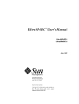
1.3 Performance Advantage of VIS
Figure 1-1 illustrates the performance advantage of a partitioned 8 bit by 16 bit
multiplication i.e four 8 x 16 multiplies performed in a single cycle resulting in a
4 times speedup.
31
W
63
63
Figure 1-1
X
23
15
7
15
0
*
*
*
*
A *W
B *X
C *Y
D *Z
47
31
0
Z
Y
31
47
D
C
B
A
15
0
Four multiplications performed in a single cycle
Sun Microsystems, Inc.
3
VIS Instruction Set User’s Manual
Sun Microelectronics
4
UltraSPARC Concepts
2
2.1 Overview
This chapter presents the major hardware features of the new UltraSPARC microprocessor implementing the 64-bit SPARC V9 architecture that give accelerated
graphics performance using VIS. Topics included in this chapter are descriptions
of:
•
•
•
•
•
•
Functional Units Of the UltraSPARC-I
UltraSPARC-I front end
Integer Execution Unit (IEU)
Floating Point/Graphics Unit (FGU)
System Interface
Processor Pipeline
Sun Microsystems, Inc.
5
VIS Instruction Set User’s Manual
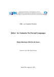
2.2 The Functional Units of Ultrasparc-I
Figure 2-1 is a simplified block diagram identifying the major functional units
that make up UltraSPARC-I.
1.
The front end which is the Prefetch/Dispatch Unit (PDU) prefetches
instructions based upon a dynamic branch prediction mechanism and a
next field address which allows single cycle branch following. By
predicting branches accurately, which typically is better than 90% of the
time, the front end can supply four instructions per cycle to the core
execution block.
2.
The Integer Execution Unit (IEU) performs all integer arithmetic/logical
operations. The IEU incorporates a novel 3-D register file supporting 7 read
and 3 write ports.
3.
The Floating-Point/Graphics Unit (FGU) integrates five functional units
and a Register File made up of 32 64-bit registers. The floating point adder,
multiplier and divider, performing all floating point operations, have been
augmented by a graphics adder and multiplier to perform the partitioned
integer operations required by the VIS Instruction Set.
4.
The Load Store Unit (LSU) executes all instructions that transfer data
between the memory hierarchy and the two register files in the IEU and
the FGU. Included in this unit are the Data Cache (D-Cache), Load Buffer,
Store Buffer and Data Memory Management Unit DMMU.
5.
The External Cache (E-Cache) which services misses from the Instruction
Cache (I-Cache) in the UltraSparc front end and the D-Cache of the LSU.
Sun Microelectronics
6
2. UltraSPARC Concepts
I-Cache
IMMU
Branch
Unit
Branch
Prediction
and
Next Field
Prefetch and
Dispatch Unit
Integer
Execution
Unit
Load/
Store
Unit
Floating
Point/
Graphics
Unit
Load
Buffer
D-Cache
Store
Buffer
DMMU
Second-Level Cache Interface/
System Interface
SecondLevel
Cache
Data
Buffer
128+16 (parity)
Figure 2-1
System
Data
System
128+16 (ECC)
System
Address
35+1 (parity)
Simplified Block Diagram of UltraSPARC-I
Sun Microsystems, Inc.
7
VIS Instruction Set User’s Manual
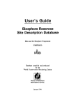
2.3 The UltaSPARC Front End
The UltraSPARC front end is essentially the Prefetch/Dispatch Unit (PDU).
Figure 2-2 illustrates the major components of the UltraSPARC-I front end.
Next
Field
Branch
I-Cache
Prediction
12
12
4
VA
41
Second
Level
Cache
128
PreDecoded
Unit
Prefetch
Unit
PA
128
44
4 x 76
Instruction
Buffer
12
Entry
IMMU
64
Entries
ITLB
Dispatch
Unit
4
Instructions
Load/
Store
Figure 2-2
Floating
Point/
Graphics
Integer
Execution
Branch
UltraSPARC-I Front End
Instructions are prefetched from a pseudo 2-way 16kbyte instruction cache. Each
line in the I-Cache contains 8 instructions (32 bytes). Every pair of instructions
has a 2-bit branch prediction field which maintains history of a possible branch in
the pair. The four prediction states are the conventional strongly taken, likely taken, strongly not-taken and likely not-taken. The advantage of the in-cache prediction scheme is that it avoids the alias problems encountered in branch history
Sun Microelectronics
8
2. UltraSPARC Concepts
buffer and other similar structures. Every single branch in the I-Cache has its
dedicated prediction bits (ignoring the rare case of branch couples), which translates into a successful prediction rate of 88% for integer code, 94% for floatingpoint (SPEC92) and 90% for typical database applications.
Every group of four instructions in the cache has a “next field” which is simply a
pointer to where the prefetcher should access instructions for the very next cycle.
In the case of sequential code or for code with a branch predicted not-taken, the
next field points to the next 4 instructions in the cache. The next field will contain
the I-Cache index (including the set) of the branch target if a branch is predicted
taken. The advantage of this scheme is that the next field can always be fed back
to the I-Cache without qualifying a possible branch. In order to provide a one-cycle loop back to the I-Cache, a fast dual-ported structure was used to implement
the next field and the branch prediction bits. Only one set of the cache is accessed
during a fetch, saving power and reducing the cache cycle time. Both tags are
read so that an incorrect set prediction can be corrected. A two-cycle penalty occurs for a set misprediction. The next field mechanism allows UltraSPARC to
speculate 5 branches deep representing up to 18 instructions.
Instructions prefetched by the PDU are expanded to 76 bits in order to facilitate
decoding done by the grouping logic. These decoded instructions are forwarded
to a 12-deep instruction buffer which allows the prefetcher to get ahead of the execution units. As long as the instruction queue is kept almost full, cache miss, set
miss and micro-TLB (uTLB) miss penalties can be hidden from the execution
units.
A single entry uTLB provides the prefetcher with a local copy of the last virtualto-physical address translation. In the rare case of a uTLB miss a 1-cycle fetch
penalty is incurred in order to get the address from the 64-entry fully associative
instruction-TLB (iTLB).
The grouping logic always looks at the next four candidates in the instruction
buffer and based on resource availability and dependencies, issues up to four instructions. Maintaining more than one Program Counter (PC) per group allows
UltraSPARC to dispatch, in the same group, instructions from two adjacent basic
blocks.
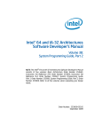
2.3.1
Integer Execution Unit (IEU)
The Integer Execution Unit (IEU) performs integer computation for all integer
arithmetic/logical operations The IEU as depicted in Figure 2-3 includes
Sun Microsystems, Inc.
9
VIS Instruction Set User’s Manual
dual 64-bit adders implemented in dynamic circuitry, an inverter and very little
extra logic (muxes for immediate bypasses) that form the basic cycle time of the
machine (together with the data cache access).
Dispatch Unit
7 read addresses
Integer
Register File
Store Data
64
3x64
8 windows
4 global sets
2x64
2x64
2x64
ALU1
ALU0
VA
Adder
44
Load/Store
Unit
Shifter
Registerbased
CTIs
Condition
Codes
Integer
Multiply/
Divide
Load Data
64
64
Completion Unit
Figure 2-3
Sun Microelectronics
10
Integer Execution Unit
64
2. UltraSPARC Concepts
A separate 64-bit adder is provided for virtual address additions for memory instructions. A simple 64-bit integer multiplier and divider complement the IEU.
The multiplication unit implements a 2-bit Booth encoding algorithm with an
“early-out” mechanism, with a typical latency of 8 clock cycles. A 1-bit non-restoring subtraction algorithm is used in the divide unit, which yields a latency of
67 clock cycles for a 64-bit by 64-bit division.
2.3.2
Floating Point/Graphics Unit (FGU)
The Floating-Point and Graphics Unit (FGU) as illustrated in Figure 2-4 integrates
five functional units and a 32 registers by 64 bits Register File. The floating-point
adder, multiplier and divider perform all FP operations while the graphics adder
and multiplier perform the graphics operations of the VIS Instruction Set.
Dispatch Unit
5 read addresses
3x64
Floating-Point
Graphics
Register File
32, 64b regs
Store Data
64
4x64
FP
GR
÷/√
GR
+
*
FP
64
FP
+
*
Load/
Store
Unit
Load Data
2x64
Completion Unit
Figure 2-4
Floating Point and Graphics Unit
Sun Microsystems, Inc.
11
VIS Instruction Set User’s Manual
A maximum of two floating-point/graphics Operations (FGops) and one FP
load/store operation are executed in every cycle (plus another integer or branch
instruction). All operations, except for divide and square-root, are fully pipelined.
Divide and square-root operations complete out-of-order without inhibiting the
concurrent execution of other FGops.The two graphics units are both fully pipelined and perform operations on 8 or 16-bit pixel components with 16 or 32-bit
intermediate results.
The Graphics Adder performs single cycle partitioned add and subtract, data
alignment, merge, expand and logical operations. Four 16-bit adders are utilized
and a custom shifter is implemented for byte concatenation and variable bytelength shifting. The Graphics Multiplier performs three cycle partitioned multiplication, compare, pack and pixel distance operations. Four 8x16 multipliers are
utilized and a custom shifter is implemented. Eight 8-bit pixel subtractions, absolute values, additions and a final alignment are required for each pixel distance
operation.
2.3.3
Load/Store Unit (LSU)
The Load/Store Unit (LSU) executes all instructions that transfer data between
the memory hierarchy and the Integer and Floating Point/Graphics Register files.
The LSU includes the Data Cache, Load Buffer, Store Buffer, and is very closely
coupled to the second level external cache. See Figure 2-5 for a functional diagram of the Load/Store Unit.
2.3.3.1
Data Cache
The Data Cache (D-Cache) is a 16kB, direct-mapped cache. It has a 32B (256 bits)
line size, with 16B (128 bits) sub-blocks. It is virtually-indexed and physicallytagged. The D-Cache is non-blocking and operates using a write-through, nowrite-allocate policy. Strict inclusion with respect to the E-cache is maintained, facilitating cache coherency. The D-Cache data SRAM is single-ported and can support a 64-bit load or a 64-bit store every cycle. In the event of a D-Cache miss, an
entire sub-block (16B) can be written in one clock. The D-Cache tag SRAM has
two ports, a read port and area/write port. These two ports allow a load or store
to perform a tag look-up in parallel with the allocation for an older D-Cache
miss.
2.3.3.2
Load Buffer
The load buffer can eliminate stalls caused by D-Cache misses, load-after-store
hazards, and other conflicts. Nine entries were implemented to cover the additional 6-cycle latency of a D-Cache miss/E-Cache hit. A rate of one load E-Cache
Sun Microelectronics
12
2. UltraSPARC Concepts
hit per cycle can be sustained. Early compiler results indicate that more than 50%
(statically) of the loops in SPECfp92 are amenable to be software pipelined based
on the E-Cache latency. These loops represent an even larger component of the
dynamic execution time. The load buffer is organized as a circular queue.
Register File
2x64
VA
Adder
44
D-Cache
VA
D-Cache
Tags
=
DTLB
hit/miss?
41
PA
128
64
Store
Buffer
Load
Buffer
64
Integer/FP
Completion
Units
address
address
64
data
128
Second-Level Cache
Figure 2-5
Load/Store Unit
Each load is enqueued with an indication of whether it hits or misses the DCache and this information is tracked for the lifetime of the operation, even in the
presence of snoops. An age-based, associative comparison is performed in order
Sun Microsystems, Inc.
13
VIS Instruction Set User’s Manual
to “adjust” the raw D-Cache hit/miss indicator of the incoming load to account
for allocations or victimizations that may be performed by pending loads to that
D-Cache line. Thus, the D-Cache tags are only checked once.
2.3.3.3
Store Buffer
The 8-entry Store Buffer (each entry accounts for a 64-bit datum and its corresponding address) provides a temporary holding place for store operations until
they can be “committed” and the D-Cache and/or the E-Cache is available. The
E-Cache update is a two-step process. First, the E-Cache tags are checked for
hit/miss. Then, the E-Cache write occurs at some later time. The E-Cache tag and
data RAM accesses are decoupled so that a tag check can occur in parallel with
the E-Cache data write of an older store, thus maintaining a throughput of one
store per clock. Additionally, consecutive stores to the same E-Cache line (64B)
typically require only a single tag check, thus minimizing tag check transactions.
Store compression combines the last two entries in the store buffer when they
both write to the same 16B block. Any number of stores can be combined into one
transaction. Hence, the number of data write transactions are minimized, an important concern since all stores must update the E-Cache given that the D-Cache
is a write-through design.
2.3.3.4
Data Memory Management Unit (DMMU)
The data memory management unit DMMU incorporates a fully associative, 64entry Translation Lookaside Buffer (TLB) that provides one virtual-to-physical
address translation per cycle. Any combination of the 8kB, 16kB, 512kB and 4MB
supported page sizes is allowed. A TLB miss is handled by software for simplicity and flexibility with a simple hardware assist provided for speed. Two readonly registers contain pointers to translation table entries from the Translation
Storage Buffer (TSB), defined as a simple, direct-mapped software cache. A separate set of 8 global registers is also accessible as temporary storage.
2.3.4
External Cache
The External Cache is used to service misses from the I-Cache in the UltraSPARC
front end and the D-Cache in the LSU. It is a physically addressed and physically
tagged SRAM implementation. The line size is 64-bytes. E-Cache sizes from
512kB to 4MB are supported with E-Cache data protected by byte parity. An internal, delayed write buffer minimizes the write after read (WAR) penalty. Writes
to the SRAM core are delayed until the next write arrives and the buffer is fully
bypassed inside the SRAM.
Sun Microelectronics
14
2. UltraSPARC Concepts
The additional latency for an internal cache miss and E-Cache hit is 6 cycles (3 internal and 3 external). Reads can be completed in every cycle, with data driven
the second cycle after address and control signals. UltraSPARC does not differentiate between burst reads and two consecutive reads; signals used for a single
read are simply replicated for each subsequent read. The reads are fully pipelined
and thus full throughput is achieved.
Writes can also be completed every cycle, with data driven the cycle after address
and control. A dead cycle is created when switching direction on the data bus, to
avoid overlapping drivers. The total write-after-read (WAR) penalty is two cycles.
There is no read-after-write (RAW) penalty.
2.3.5
System Interface
A complete UltraSPARC-I subsystem consisting of the UltraSPARC-I processor,
synchronous SRAM components for the External Cache tags and data and two
UltraSPARC-I Data Buffer (UDB) chips is shown in Figure 2-6.
Prefetch
16
128
Unit
128
Load/
Store
Unit
Second
Level
Cache/
Memory
Interface
Unit
External
Cache
Tags
25+3(parity)
18
External
Cache
128
System
Address
Distributed
Arbitration
Figure 2-6
Data
Buffer
(UDB)
128+16
(parity)
System Data
128+16
(ECC)
System
UltraSPARC-I System Interface
Sun Microsystems, Inc.
15
VIS Instruction Set User’s Manual
The UDBs serve to electrically isolate the interaction between the CPU and ECache from the system bus and operate at the system clock frequency, which can
be either 1/2 or 1/3 of the processor clock. Collectively, the UDBs have FIFOs for
eight 16-byte noncacheable stores, one 64-byte read buffer, two 64-byte write
buffers, and a 64-byte copyback buffer. The large number of outstanding 16-byte
stores is useful for maintaining peak store bandwidth to a frame buffer.
System transactions are packet based, in that address and data transfers are disjoint non-interfering events. A 36-bit address bus is used to deliver two-cycle request packets that begin a transaction. This bus can be shared by up to three
other masters, in addition to a centralized system controller.
Arbitration is distributed. Each master on the address bus has the same logic and
sees all requests for the bus. There are five potential requests: four potential masters plus one from a high priority system controller. Arbitration is round-robin
with a hysteresis effect to reduce latency for the last master. This helps reduce latency for bursts of transactions from the same master. There is also a special parking mode for uniprocessors that typically reduces arbitration latency to zero, by
keeping UltraSPARC enabled onto the address bus between transactions.
2.4 Processor Pipeline
The functions performed by the IEU, LSU and FGU are implemented in a dual
9-stage pipeline. Most instructions go through the pipeline in exactly 9 stages.
The instructions are considered terminated after they go through the last stage
(W), after which, changes to the processor state are irreversible. Figure 2-7 shows
a diagram of the integer and floating-point pipeline stages. Three additional stages are added to the integer pipeline to make it symmetrical with the floatingpoint pipeline. This simplifies pipeline synchronization and exception handling
and eliminates the need to implement a floating-point queue.
Floating-point instructions with a latency greater than 3 (divide and square root)
behave differently than other instructions, in the sense that the pipe is “extended” when the instruction reaches stage N1. Memory operations are allowed to
proceed asynchronously with the pipeline in order to support latencies longer
than the latency of the on-chip data cache.
Sun Microelectronics
16
2. UltraSPARC Concepts
Integer Pipe
E-Execute
C-Cache Access
N1-D-Cache Hit/Miss
N2-FP Pipe Sync
E
F
D
C
N1 N2
N3 W
G
F-Fetch
D-Decode
G-Group
R X1 X2 X3
N3-Traps are resolved
W-Write
R-Register
X1-Start Execution Continued
X2-Execution
X3-Finish Execution
Floating-point/Graphics Pipe
Figure 2-7
UltraSPARC-I 9-Stage Dual Pipeline.
2.5 Pipeline Stage Description
2.5.1
Stage 1: Fetch (F) Stage
In this stage instructions are fetched from the instruction Cache (I-Cache) and
placed in the Instruction Buffer, from where they will be selected for execution.
Up to four instructions are fetched, along with branch prediction information, the
predicted target address of a branch, and the predicted set of the target. The high
bandwidth provided by the I-Cache (4 instructions/cycle) allows the UltraSPARC
to prefetch instructions ahead of time based on the current instruction flow and
on branch prediction. Providing a fetch bandwidth greater than or equal to the
maximum execution bandwidth assures that, for well behaved code, the processor does not starve for instructions. Exceptions to this rule occur when branches
are hard to predict, when branches are very close to each other, or when the
I-Cache miss rate is high.
Sun Microsystems, Inc.
17
VIS Instruction Set User’s Manual
2.5.2
Stage 2: Decode (D) Stage
In this stage the fetched instructions are pre-decoded and sent to the Instruction
Buffer. The pre-decoded bits generated during this stage accompany the instructions during their stay in the Instruction Buffer. Upon reaching the next stage
(where the grouping logic lives) these bits speed up the parallel decoding of up
to 4 instructions.
While it is being filled, the Instruction Buffer also presents up to 4 instructions to
the next stage. A pair of pointers manage the Instruction Buffer, ensuring that as
many instructions as possible are presented in order to the next stage.
2.5.3
Stage 3: Grouping (G) Stage
This stage’s main task is to group and dispatch a maximum of four(4) valid instructions in one cycle. It receives a maximum of 4 valid instructions from the
Prefetch and Dispatch Unit (PDU), it controls the Integer Unit Register File
(IURF), and it routes valid data to each integer functional unit. The G Stage sends
up to two floating-point or graphics instructions out of the four candidates to the
Floating-Point and Graphics Unit (FGU). Additionally the logic in the G Stage is
responsible for comparing register addresses for integer data bypassing and for
handling pipeline stalls due to interlocks.
2.5.4
Stage 4: Execution (E) Stage
In this stage data from the integer register file is processed by the two integer
ALUs during this cycle (if the instruction group includes ALU operations). Results are computed and are available for other instructions (through bypasses) in
the very next cycle. The virtual address of a memory operation is also calculated
in this stage in parallel with ALU computation.
In the Floating-point/Graphics pipe, this stage corresponds to the Register (R)
Stage of the FGU. The floating-point register file is accessed during this cycle. The
instructions are also further decoded and the FGU control unit selects the proper
bypasses for the current instructions.
2.5.5
Stage 5: Cache Access (C) Stage
In this stage the virtual addresses of memory operations calculated in the E Stage
are sent to the tag RAM to determine if the access (load or store type) is a hit or a
miss in the D-Cache. In a parallel operation, the virtual address is sent to the data
Sun Microelectronics
18
2. UltraSPARC Concepts
MMU to be translated into a physical address. On a load when there are no other
outstanding loads, the data array is accessed so that the data can be forwarded to
dependent instructions in the pipeline as soon as possible.
ALU operations executed in the E Stage generate condition codes in the C Stage.
The condition codes are sent to the PDU, which checks whether a conditional
branch in the group was correctly predicted. If the branch was mispredicted, earlier instructions in the pipe are flushed and the correct instructions are fetched.
The results of ALU operations are not modified after the E Stage; the data merely
propagates down the pipeline (through the annex register file), where it is available for bypassing for subsequent operations.
In the Floating-point/Graphics pipe, this stage is the X1 Stage. Instructions start
their execution during this stage. Instructions of latency one also finish their execution phase during the X1 Stage.
2.5.6
Stage 6: N1 Stage
In this stage a data cache miss/hit or a TLB miss/hit is determined. If a load
misses the D-Cache, it enters the Load Buffer. The access will arbitrate for the ECache if there are no older unissued loads. If a TLB miss is detected, a trap will
be taken and the address translation obtained by a software routine. The physical
address of a store is sent to the Store Buffer during this stage. To avoid pipeline
stalls when store data is not immediately available, the store address and data
parts are de-coupled and sent to the Store Buffer separately.
In the Floating-point/Graphics pipe this is the second execution stage (X2) where
execution continues for most instructions.
2.5.7
Stage 7: N2 Stage
In this stage the Integer Pipe essentially waits for the Floating-point/Graphics
pipe to complete. Most floating-point instructions in Floating-point/Graphics
pipe finish their execution during this stage. After N2, data can be bypassed to
other stages or forwarded to the data portion of the Store Buffer. All loads that
have entered the Load Buffer in N1 continue their progress through the buffer;
they will reappear in the pipeline only when the data comes back.
2.5.8
Stage 8: N3 Stage
In this stage the Integer and Floating-point/Graphics pipes converge to resolve
traps.
Sun Microsystems, Inc.
19
VIS Instruction Set User’s Manual
2.5.9
Stage 9: Write (W) Stage
In this stage all results (integer and floating-point) are written to the register files.
All actions performed during this stage are irreversible. After this stage, instructions are considered terminated
2.6 Performance Improvement
The expanded hardware capabilities of the UltraSPARC-I processor offer you a
sustained execution rate of four instructions per cycle even in the presence of
conditional branches and cache misses. Typically this may include a simultaneous execution of 2 floating point/graphics, 1 integer and 1 load/store instruction per cycle.
Sun Microelectronics
20
Development Flow
3
3.1 Overview
This chapter presents the applications development process and introduces the
tools for developing applications, debugging and performance monitoring.
Topics included in this chapter are:
•
•
•
•
•
Development Process Overview
SPARCompiler 4.x (SC 4.x)
Use of software VIS Simulator
Use of INCAS (It’s a Nearly Cycle Accurate Simulator)
Process Tuning
Sun Microsystems, Inc.
21
VIS Instruction Set User’s Manual
3.2 Development Process Overview
Code written using the VIS instruction set may be compiled and run in three
ways:
1.
Compile your VIS code using the SPARCompiler 4.x directly to generate
object code for execution on the UltraSPARC CPU.
2.
Compile your VIS code using any compatible, not necessarily a
SPARCompiler 4.x, C compiler and link with “libvis_sim.so” or “libvis_
sim.a”, a VIS instruction simulator, to resolve VIS function calls. The VIS
instruction simulator substitutes standard C implementations for the VIS
instruction set which permits you to run your code on any compatible
processor, not necessarily an UltraSPARC-I, to perform debugging and
algorithm validation.
3.
Compile and specially process your VIS code to run on INCAS (It’s a
Nearly Cycle Accurate Simulator), which is a nearly cycle accurate model
of the UltraSPARC-I processor. This permits you to do independent code
performance prediction, cycle counting and debugging.
3.3 VIS Software Developer’s Kit
The VIS Software Developer’s Kit (VSDK) is a set of tools and sample code designed to help in the development of VIS code. A bulk of the sample code in this
and later chapters of this guide can be found in the VSDK. Before using the
VSDK, the following environment variables must be defined:
VSDKHOME - the root directory of the VIS Software Developers Kit
INCASHOME - the root directory of INCAS
If the SPARCompiler 4.x being used to compile VIS code is not the default compiler, then the environment variable, CC, needs to be set to point to the SC 4.x
compiler, in order for the Makefiles in the VSDK to work.
An example environment variable definition is:
% setenv VSDKHOME /opt/SUNWvsdk
% setenv INCASHOME /opt/SUNWincas
Sun Microelectronics
22
3. Development Flow
3.4 SPARCompiler 4.x (SC 4.x)
The SPARCompiler 4.x (SC4.0 or later) is the latest SUN compiler release and is
backward compatible with the previous releases of SPARCompilers supporting
UltraSPARC development. By incorporating a new flexible flag scheme, the
SPARCompiler 4.x lets you target the UltraSPARC processor implementation of
the SPARC V9 architecture with the VIS instruction set extension. Additionally
the SPARCompiler 4.x offers improved runtime performance, profile feedback
based optimization and improved parallelization support.
3.4.1
Compiling VIS Code
When compiling VIS code on a machine incorporating the UltraSPARC CPU,
close to optimum performance will be achieved by electing to use the -fast compile option since this option chooses the fastest code generation option available
on the compile time hardware. For routines using VIS code, you must include the
vis.il file on the command line to resolve VIS function calls. This replaces each
VIS instruction with an inline assembly macro implementation. An example, illustrating the assembly implementation of vis_fpadd16() is presented in section
3.4.2 on page 23.
If you use -fast with additional optimization option levels -xO[1|2|3|4|5], you
must take note that the last optimization level specified in the options string is
used, so the basic optimization level of -fast may be overridden.
When compiling VIS code you must specify the target processor by setting the
flag -xchip=ultra and identify the instructions that the compiler may use by setting the flag -xarch=v8plusa. The following example illustrates the compilation
and linking of two VIS files:
cc -c vis.il -xchip=ultra -xarch=v8plusa file1.c
cc -c vis.il -xchip=ultra -xarch=v8plusa file2.c
cc file1.o file2.o -o file
Setting the v8plusa flag specifies the 32 bit subset of the 64 bit v9 architecture including the VIS extension. If you would like to generate assembly code say,
file1.s, then use the -S flag. i.e.
cc -S vis.il -xchip=ultra -xarch=v8plusa file1.c
3.4.2
Inline Assembly Implementation of vis_fpadd16()
Code Example 3-1 shows the assembly implementation of inline macro
vis_fpadd16()
Sun Microsystems, Inc.
23
VIS Instruction Set User’s Manual
Code Example 3-1
Inline Assembly Implementation of vis_fpadd16()
.inline vis_fpadd16,4
std
%o0,[%sp+0x48]
ldd
[%sp+0x48],%f4
std
%o2,[%sp+0x48]
ldd
[%sp+0x48],%f10
fpadd16 %f4,%f10,%f0
.end
3.5 VIS Simulator
The VIS simulator is a development and debugging tool which permits you to
test your VIS code on any platform.
Linking with the simulator library “libvis_sim.so” or “libvis_sim.a”, supplied
with the developers kit, resolves the VIS function calls with a C simulation of the
VIS instruction set. The following example shows the compilation of two VIS
code files and the linking with the simulator to create the executable binary:
cc -c file1.c
cc -c file2.c
cc file1.o file2.o -o file -L$VSDKHOME/vis_sim -lvis_sim
The resulting binary will run on any machine and produce results that are identical to those produced by the UltraSPARC specific binary. While executing quite
slowly this option permits independent verification of algorithms and debugging
VIS code in an independent environment. The following is an example of a simulator implementation of vis_fpadd16().
3.5.1
Example of Simulator Implementation of vis_fpadd16()
Code Example 3-2 illustrates the simulator implementation of the partitioned addition of two 4x16 bit partitioned values.
Code Example 3-2
Simulator Implementation of vis_fpadd16()
union vis_dreg_overlay {
vis_d64 d64;
vis_f32 f32[2];
vis_u32 u32[2];
vis_s32 s32[2];
vis_u16 u16[4];
vis_s16 s16[4];
vis_u8 u8[8];
vis_s8 s8[8];
unsigned long long ull;
struct {
void *u, *l;
} x;
};
Sun Microelectronics
24
3. Development Flow
vis_d64;
vis_fpadd16(vis_d64 frs1, vis_d64 frs2);
{
union vis_dreg_overlay op1, op2, dest;
op1.d64 = frs1;
op2.d64 = frs2;
dest.s16[0] = op1.s16[0]
dest.s16[1] = op1.s16[1]
dest.s16[2] = op1.s16[2]
dest.s16[3] = op1.s16[3]
return dest.d64
+
+
+
+
op2.s16[0];
op2.s16[1];
op2.s16[2];
op2.s16[3];
}
3.6 Use of INCAS
3.6.1
What Is INCAS?
INCAS (It’s a Near Cycle Accurate Simulator), is a near cycle accurate model of
the UltraSPARC-I processor. INCAS offers you a convenient way to do code performance prediction cycle counting and to examine processor status at each cycle
to assist in debugging and optimizing your code.
3.6.2
Limitations of Incas Simulation
INCAS models the UltraSPARC-I processor, including the instruction cache, the
data cache and the external or 2nd level cache quite accurately. However, the interaction of the processor with the system controller and main memory is modeled at a lesser level of accuracy as shown in Figure 3-1 .
Sun Microsystems, Inc.
25
VIS Instruction Set User’s Manual
UltraSPARC-I processor with
16 Kbytes Instruction Cache
& 16 Kbytes Data Cache
128 bit wide bus
INCAS accurate
External or 2nd Level Cache
512 Kbytes to 4 Mbytes
System Controller
INCAS less accurate
Main Memory
Figure 3-1
INCAS Accuracy Model
Therefore, when working with large data sets, where 2nd level cache misses and
hence interaction with main memory may be more frequent, the INCAS cycle
count may be off the mark resulting in a cycle count that may be greater or less
than that achieved on a real UltraSPARC system. In general, the results from
INCAS should be treated as “ball park” figures and not as hard numbers attainable on a real system.
In reality, the number of cycles a section of C code takes to run does not only depend upon itself. Adjacent code immediately before and after the execution segment also affect the cycle count because the compiler optimizes the code based on
the whole program when generating the binary. Also, optimizing compilers may
not produce the same binary instructions for a code segment compiled alone, versus those compiled as part of a larger program.
Sun Microelectronics
26
3. Development Flow
3.6.3
Preparing To Use INCAS
Since INCAS is a simulator for a processor, it does not include operating system
services. Therefore, before you run your binary, it is recommended that you make
the following modifications to your code and rebuild your binary before running
it on INCAS:
1.
Modify your code to eliminate all system calls such as malloc, free, scanf,
printf, etc by changing them to incas_malloc, incas_free, incas_scanf,
incas_printf etc. and linking with “$INCASHOME/util/incas_utils.o”.
Actually, not including them in your code is preferable.
2.
Replace all dynamically located arrays and variables by statically declared
ones. For example, replace:
char *a;
a = malloc(512);
by:
char a[512];
3.
Insert pseudo breakpoint routines into your code:
sim_break0();
vis_fpadd16(a, b);
sim_break1();
where:
void sim_break0(){ }
void sim_break1(){ }
4.
Re-compile and statically link your VIS code, using the -dn option, with
INCAS utility routines “incas_utils.o”, the map file “prom.ld”, traps
routines “traps.o” and static library “libc.a”. When compiling INCAS
modified code you may use all of the compiler flags as if compiling for
execution on the UltraSPARC.
cc -c vis.il -xchip=ultra -xarch=v8plusa file1.c
cc -c vis.il -xchip=ultra -xarch=v8plusa file2.c
ld -dn -M prom.ld traps.o incas_utils.o file1.o file2.o \
/usr/lib/libc.a -o file
There is a makefile in directory $VSDKHOME/examples/src. You can use
it to prepare the binary for the following sections.
make -f Makefile.example3
Sun Microsystems, Inc.
27
VIS Instruction Set User’s Manual
Because INCAS calculates the processor states cycle by cycle it is very computationally intensive. It is therefore recommended that you remove all nonessential
functions and statements from your code and concentrate on those parts that you
wish to debug or cycle count.
3.6.4
Starting INCAS
To start INCAS, run the script "$INCASHOME/bin/incas_startup". You should
see screen output similar to following:
Incas Release 2.0 - Beta
Configuration phase pwd is "/opt/SUNWincas/lib".
Preprocessing configuration file "/opt/SUNWincas/lib/us-1.conf".
Parsing configuration file "/opt/SUNWincas/lib/us-1.conf".
Creating C module classes.
Creating module instances and interfaces.
Performing interface configurations.
Performing shared object registrations.
Performing shared object lookups.
Performing interface configuration verifications.
Reading ui commands from "/opt/SUNWincas/lib/incasrc".
Negative phase is active.
ieu1:
incasrc is a command file, that is executed by INCAS at start up. These commands typically set up some environment variables and some common convenience aliases.
3.6.5
Getting Help
You can get information on commands at any point in INCAS with the command
"help". Note, however, that each module has some unique commands. A list of
INCAS commands available in “help” can be found in the file
"$INCASHOME/lib/command.list". For a comprehensive description of INCAS
commands refer to the INCAS Users Guide 2.0 found in $INCASHOME/manuals/INCASuserguide.ps.
3.6.6
Interrupting and Quitting INCAS
To interrupt and exit INCAS at any time enter your interrupt character, which is
<CTRL>-C by default. The INCAS prompt will return after it is interrupted. Use
command "quit" to exit INCAS.
Sun Microelectronics
28
3. Development Flow
3.6.7
Using INCAS for Cycle Counting
The following illustrates the use of INCAS on VIS code example “vis_example3”
described in section 3.6.9. To perform cycle counting on the binary file
“vis_example3”:
1.
Load the Binary File into RAM1 starting at address 0:
ieu1: load 0 ram1 vis_example3
2.
Set Breakpoints where you want to check the cycle count. See file
"vis_example3.c" in directory "$VSDKHOME/examples/src" and code
listing in section 3.6.9 for corresponding location of the breakpoints.
ieu1: breakpoint add &vdk_vis_blend88
ieu1: breakpoint add &exit
3.
Start cycle counting with the command "run". When the simulation reaches
a breakpoint, use the command "time" to check the current cycle count at
that point.
ieu1: run
ieu1: breakpoint 1 (stage G) at vdk_vis_blend88 (0x8518)
encountered.
ieu1: time
real time Feb 6 19:09:41.380477 user time 0.330000
0.100000
cycle count: 843 (1960.47 cps = 7.06 MCPH)
instr count: 68 (158.14 ips = 0.57 MIPH)
cpi: 12.397, ipc: 0.081
Maximum resident set size: 0 pages
system time
ieu1: run
ieu1: breakpoint 2 (stage G) at exit (0x85ac) encountered.
ieu1: time
real time Feb 6 19:09:47.609686 user time 0.35740 system time
0.107334
cycle count: 969 (2115.38 cps = 7.62 MCPH)
instr count: 95 (207.39 ips = 0.75 MIPH)
cpi: 10.200, ipc: 0.098
Maximum resident set size: 0 pages
4.
Repeat this process throughout your code. The difference of the cycle
counts between two breakpoints gives you the number of cycles the code
between the two breakpoints takes to run.
Sun Microsystems, Inc.
29
VIS Instruction Set User’s Manual
5.
3.6.8
You can put INCAS commands into a file and run them in batch mode. See
file "timing.cmd" for an example. Be sure to put the command "wait" after
each "run" command, so that INCAS will wait for the completion of the
"run" command before executing the "time" command to show the cycle
count. All INCAS screen output is also saved in a file named "incas.log".
This file can then be used later for further analysis.
Using INCAS For Debugging
INCAS permits you to examine the processor status at each cycle. Remember,
however, that INCAS is a simulator, not a debugger. You can examine processor
status but can not change it. Because INCAS works on assembly level and below,
it is more convenient to have assembly listing of your code on hand for reference.
To generate an assembly listing, use the -S option in the compiler. There are several watches which can be set to monitor different activities. Some particularly
useful watches are:
•
•
•
•
ieu1.watchpipe - monitors the status of the pipeline
ieu1.watchload - monitors the loading of an instruction
ieu1.watchdisp - monitors the dispatching of an instruction
ieu1.watchdone - monitors the finishing of an instruction
The following example is a sample debug session based on code
"vis_example3.c". You can find the source code "vis_example3.c", its assembly
listing "vis_example3.s", and INCAS log file "vis_example3.log" in the directory
"$VSDKHOME/examples/src". The source code and assembly listing are also
presented in section 3.6.9 .
1.
Start INCAS as described in section 3.6.4 on page 28
2.
Load your Binary File e.g. “vis_example3” into RAM1 starting at address 0
with the following command:
ieu1: load 0 ram1 vis_example3
3.
You may set breakpoints where you want to examine the code in detail. See
file "vis_example3.s" in directory "$VSDKHOME/examples/src" or in
section 3.6.9 for corresponding location of the breakpoints.
ieu1: breakpoint add &vdk_vis_blend88+0x38
ieu1: breakpoint add &vdk_vis_blend88+0x64
4.
Start the simulation with the command "run". The simulation will stop
when it reaches a breakpoint.
ieu1: run
ieu1: breakpoint 1 (stage G) at vdk_vis_blend88+0x38 (0x8550)
Sun Microelectronics
30
3. Development Flow
encountered.
5.
You may check the content of integer registers at any point with the
command "ieu1.iregs" ("iregs" when you focus on "ieu1").
ieu1: iregs
Youngest registers in
INS
0: 0x00000000007ffef8
1: 0x00000000007ffef0
2: 0x00000000007ffee8
3: 0x00000000007ffee0
4: 0xXXXXXXXXXXXXXXXX
5: 0xXXXXXXXXXXXXXXXX
6: 0x00000000007ffe80
7: 0x0000000000008594
y:
sp:
fp:
window 2:
LOCALS
0xXXXXXXXXXXXXXXXX
0xXXXXXXXXXXXXXXXX
0xXXXXXXXXXXXXXXXX
0xXXXXXXXXXXXXXXXX
0xXXXXXXXXXXXXXXXX
0xXXXXXXXXXXXXXXXX
0xXXXXXXXXXXXXXXXX
0xXXXXXXXXXXXXXXXX
0xXXXXXXXX
0x00000000007ffe20
0x00000000007ffe80
OUTS
0x000000000ff00ff0
0x0000000000000018
0xXXXXXXXXXXXXXXXX
0xXXXXXXXXXXXXXXXX
0xXXXXXXXXXXXXXXXX
0xXXXXXXXXXXXXXXXX
0x00000000007ffe20
0xXXXXXXXXXXXXXXXX
GLOBALS
0x0000000000000000
0xXXXXXXXXXXXXXXXX
0xXXXXXXXXXXXXXXXX
0xXXXXXXXXXXXXXXXX
0xXXXXXXXXXXXXXXXX
0xXXXXXXXXXXXXXXXX
0xXXXXXXXXXXXXXXXX
0xXXXXXXXXXXXXXXXX
memory+0x6ffe20
memory+0x6ffe80
pstate: 0x01c cle=0 tle=0 vg=0 mg=0 mm=0 red=0 pef=1 am=1 priv=1 ie=0 ag=0
ccr:
0x00 XCC: - - - ICC: - - - pil:
0xX
Window state registers:
cwp=2, cansave=3, canrestore=3, otherwin=0, cleanwin=6, other=0, normal=0
6.
The content of floating point registers may be examined with the command
"ieu1.fregs" ("fregs" when you focus on "ieu1").
ieu1: fregs
f00: 2.36720e-29
f04:
0.00000
f08: 2.36720e-29
f12:
0.00000
f16:XXXXXXXXXXXXX
f20:XXXXXXXXXXXXX
f24:XXXXXXXXXXXXX
f28:XXXXXXXXXXXXX
df00: 6.46621e-232
df08:XXXXXXXXXXXXX
df16:XXXXXXXXXXXXX
df24:XXXXXXXXXXXXX
df32:XXXXXXXXXXXXX
df40:XXXXXXXXXXXXX
df48:XXXXXXXXXXXXX
df56:XXXXXXXXXXXXX
fprs:
fsr:
gsr:
7.
f01: 2.36720e-29
f05:
0.00000
f09:XXXXXXXXXXXXX
f13:
0.00000
f17:XXXXXXXXXXXXX
f21:XXXXXXXXXXXXX
f25:XXXXXXXXXXXXX
f29:XXXXXXXXXXXXX
df02:
0.00000
df10:XXXXXXXXXXXXX
df18:XXXXXXXXXXXXX
df26:XXXXXXXXXXXXX
df34:XXXXXXXXXXXXX
df42:XXXXXXXXXXXXX
df50:XXXXXXXXXXXXX
df58:XXXXXXXXXXXXX
f02:
0.00000
f06:
0.00000
f10:OLDER[H]
f14:OLDER[G]
f18:XXXXXXXXXXXXX
f22:XXXXXXXXXXXXX
f26:XXXXXXXXXXXXX
f30:XXXXXXXXXXXXX
f03:
0.00000
f07:
0.00000
f11:OLDER[H]
f15:OLDER[G]
f19:XXXXXXXXXXXXX
f23:XXXXXXXXXXXXX
f27:XXXXXXXXXXXXX
f31:XXXXXXXXXXXXX
df04:
0.00000
df12:
0.00000
df20:XXXXXXXXXXXXX
df28:XXXXXXXXXXXXX
df36:XXXXXXXXXXXXX
df44:XXXXXXXXXXXXX
df52:XXXXXXXXXXXXX
df60:XXXXXXXXXXXXX
df06:
0.00000
df14:XXXXXXXXXXXXX
df22:XXXXXXXXXXXXX
df30:XXXXXXXXXXXXX
df38:XXXXXXXXXXXXX
df46:XXXXXXXXXXXXX
df54:XXXXXXXXXXXXX
df62:XXXXXXXXXXXXX
0x05 fef=1, du=0, dl=1
0x0000000000000000
fcc3 fcc2 fcc1 fcc0 ns ver qne rd ftt
=
=
=
=
0
0
0 near none
invalid
overflow underflow
tem
aexc
cexc
0x00000018 scale_f=3, align=0
divzero
-
inexact
-
Cycle through a simulation with the watches turned on. “debug_ieu”, in
the following listing, is a macro that sets up some watches. It is defined in
the $INCASHOME/lib/incasrc command file.
Sun Microsystems, Inc.
31
VIS Instruction Set User’s Manual
ieu1: debug_ieu
ieu1: cycle
ieu1.watchload(983): [A]
vdk_vis_blend88+0x20 (0x836c):
ld [%sp + 0x5c], %f8
[mem addr = memory+0x6ffe7c (0x7ffe7c), %f8 = 0x0ff00ff0
(2.36720e-29)]
ieu1.watchdisp(983): [K] FP1 vdk_vis_blend88+0x48
(0x8394):
fmul8x16 %f4, %f14, %f14
ieu1.watchpipe: G E C N O P W
ieu1.watchpipe: =============
ieu1.watchpipe: K I G F E - ieu1.watchpipe: - J H - - - ui1.cyclecount: 0x000003d8
**************************CYCLE**DONE************************
ieu1: cycle
ieu1.watchdisp(984): [L] FP1 vdk_vis_blend88+0x4c
(0x8398):
fmul8x16 %f5, %f16, %f16
ieu1.watchpipe: G E C N O P W
ieu1.watchpipe: =============
ieu1.watchpipe: L K I G F E ieu1.watchpipe: - - J H - - ui1.cyclecount: 0x000003d9
**************************CYCLE**DONE************************
ieu1: cycle
ieu1.watchdone(985): [E] FP0 vdk_vis_blend88+0x30
(0x837c):
fmovs %f8, %f0
ieu1.watchpipe: G E C N O P W
ieu1.watchpipe: =============
ieu1.watchpipe: - L K I G F ieu1.watchpipe: - - - J H - ui1.cyclecount: 0x000003da
**************************CYCLE**DONE************************
In pipeline watch, each instruction is represented by a case sensitive letter and is
shown going through seven stages of the pipeline. The above example shows
three cycles of output. In the first cycle, instruction A (ld) is being loaded and instruction K (fmul8x16) is being dispatched. In the second cycle, instruction L
(fmul8x16) is being dispatched and instruction K has moved to the second stage
of the pipeline. In the third cycle, instruction E (fmovs) is finishing, instruction K
has moved to the third stage of the pipeline, and instruction L has moved to the
second stage of the pipeline.
8.
Run the simulation with some watches on. INCAS will continually output
the status changes of the watches until it reaches a breakpoint.
ieu1: debug_ieu
ieu1: run
ieu1.watchdisp(982): [I] FP0 vdk_vis_blend88+0x40
fpsub16
%f0, %f12, %f16
ieu1.watchdisp(982): [J] FP1 vdk_vis_blend88+0x44
Sun Microelectronics
32
(0x838c):
(0x8390):
3. Development Flow
fmul8x16 %f3, %f12, %f12
ieu1.watchpipe: G E C N O P W
ieu1.watchpipe: =============
ieu1.watchpipe: I G F E - - ieu1.watchpipe: J H - - - - ui1.cyclecount: 0x000003d7
**************************CYCLE**DONE************************
ieu1.watchload(983): [A]
vdk_vis_blend88+0x20
(0x836c):
ld [%sp + 0x5c], %f8
[mem addr = memory+0x6ffe7c (0x7ffe7c), %f8 =
0x0ff00ff0 (2.36720e-29)]
ieu1.watchdisp(983): [K] FP1 vdk_vis_blend88+0x48
(0x8394):
fmul8x16 %f4, %f14, %f14
ieu1.watchpipe: G E C N O P W
ieu1.watchpipe: =============
ieu1.watchpipe: K I G F E - ieu1.watchpipe: - J H - - - ui1.cyclecount: 0x000003d8
**************************CYCLE**DONE************************
ieu1.watchdisp(984): [L] FP1 vdk_vis_blend88+0x4c
(0x8398):
fmul8x16 %f5, %f16, %f16
ieu1.watchpipe: G E C N O P W
ieu1.watchpipe: =============
ieu1.watchpipe: L K I G F E ieu1.watchpipe: - - J H - - ui1.cyclecount: 0x000003d9
**************************CYCLE**DONE************************
ieu1.watchdone(985): [E] FP0 vdk_vis_blend88+0x30
(0x837c):
fmovs%f8, %f0
ieu1.watchpipe: G E C N O P W
ieu1.watchpipe: =============
ieu1.watchpipe: - L K I G F ieu1.watchpipe: - - - J H - ui1.cyclecount: 0x000003da
**************************CYCLE**DONE************************
ieu1.watchdone(986): [F] FP0 vdk_vis_blend88+0x34
(0x8380): fmovs
%f8, %f1
ieu1.watchdisp(986): [M] FP0 vdk_vis_blend88+0x50
(0x839c):
fpadd16
%f10, %f14, %f14
ieu1.watchpipe: G E C N O P W
ieu1.watchpipe: =============
ieu1.watchpipe: M - L K I G ieu1.watchpipe: - - - - J H ui1.cyclecount: 0x000003db
**************************CYCLE**DONE************************
ieu1.watchdone(987): [G] FP0 vdk_vis_blend88+0x38
(0x8384):
fpsub16
%f0, %f10, %f14
ieu1.watchdone(987): [H] FP1 vdk_vis_blend88+0x3c
(0x8388):
fmul8x16 %f2, %f10, %f10
ieu1.watchdisp(987): [N] FP0 vdk_vis_blend88+0x54
(0x83a0):
fpadd16
%f12, %f16, %f10
ieu1.watchdisp(987): [O] FP1 vdk_vis_blend88+0x58
(0x83a4):
fpack16
%f14, %f0
Sun Microsystems, Inc.
33
VIS Instruction Set User’s Manual
ieu1.watchpipe: G E C N O P W
ieu1.watchpipe: =============
ieu1.watchpipe: N M - L K I ieu1.watchpipe: O - - - - J ui1.cyclecount: 0x000003dc
**************************CYCLE**DONE************************
ieu1.watchdone(988): [I] FP0 vdk_vis_blend88+0x40
(0x838c):
fpsub16
%f0, %f12, %f16
ieu1.watchdone(988): [J] FP1 vdk_vis_blend88+0x44
(0x8390):
fmul8x16 %f3, %f12, %f12
ieu1.watchdisp(988): [P] FP1 vdk_vis_blend88+0x5c
(0x83a8):
fpack16
%f10, %f1
ieu1.watchdisp(988): [Q] vdk_vis_blend88+0x60
(0x83ac):
std %f0, [%i2]
[mem addr not valid yet, %df0 = even 0x00000000,
OLDER]
ieu1.watchpipe: G E C N O P W
ieu1.watchpipe: =============
ieu1.watchpipe: P N M - L K ieu1.watchpipe: Q O - - - - ui1.cyclecount: 0x000003dd
**************************CYCLE**DONE************************
ieu1.watchdone(989): [K] FP1 vdk_vis_blend88+0x48
(0x8394):
fmul8x16 %f4, %f14, %f14
ieu1.watchdisp(989): [R] IEU1 vdk_vis_blend88+0x64
(0x83b0): ret
[predicted branch addr = main+0x18 (0x83d0)]
ieu1.watchpipe: G E C N O P W
ieu1.watchpipe: =============
ieu1.watchpipe: R P N M - L ieu1.watchpipe: - Q O - - - ieu1: breakpoint 2 (stage G) at vdk_vis_blend88+0x64 (0x83b0)
encountered.
ui1.cyclecount: 0x000003de
**************************CYCLE**DONE************************
3.6.9
Example Program Used in Illustrating INCAS Operation
The following sections present the source code ,the assembly listing and the
INCAS command batch file for vis_example3.
3.6.9.1
Source Code for vis_example3
/*
* FUNCTION
*
vdk_vis_blend88 - blend two 8-pixel arrays
*
* SYNOPSIS
*
void vdk_vis_blend88 (vis_d64 sp1[], vis_d64 sp2[],
*
vis_d64 dp[], vis_d64 ap[]);
*
* ARGUMENT
*
sp1 pointer to 8 bytes of source data 1
Sun Microelectronics
34
3. Development Flow
*
sp2 pointer to 8 bytes of source data 2
*
dp
pointer to 8 bytes of destination data
*
ap
pointer to 8 bytes of alpha coefficient
*
* DESCRIPTION
*
Blend two arrays with a alpha coefficient array.
*
dst = alpha * src1 + (255 - alpha) * src2, (0 <= alpha <= 255)
*/
#include <stdlib.h>
#include "vis_types.h"
#include "vis_proto.h"
/***************************************************************/
void vdk_vis_blend88 (vis_d64 sp1[], vis_d64 sp2[],
vis_d64 dp[], vis_d64 ap[])
{
vis_d64 sd1, sd2, ad;
vis_d64 ones;
vis_f32 sf1h, sf2h, sf1l, sf2l;
vis_d64 adh, bdh, adl, bdl;
vis_d64 rd1h, rd2h, rd1l, rd2l;
vis_d64 rdh, rdl;
vis_d64 rd;
sd1 = sp1[0];
sd2 = sp2[0];
ad = ap[0];
vis_write_gsr(3 << 3);
ones = vis_to_double_dup(0x0ff00ff0);
adh = vis_fexpand_hi(ad);
adl = vis_fexpand_lo(ad);
bdh = vis_fpsub16(ones, adh);
bdl = vis_fpsub16(ones, adl);
sf1h = vis_read_hi(sd1);
sf1l = vis_read_lo(sd1);
rd1h = vis_fmul8x16(sf1h, adh);
rd1l = vis_fmul8x16(sf1l, adl);
sf2h = vis_read_hi(sd2);
sf2l = vis_read_lo(sd2);
rd2h = vis_fmul8x16(sf2h, bdh);
rd2l = vis_fmul8x16(sf2l, bdl);
rdh = vis_fpadd16(rd1h, rd2h);
Sun Microsystems, Inc.
35
VIS Instruction Set User’s Manual
rdl = vis_fpadd16(rd1l, rd2l);
rd = vis_fpack16_to_hi(rd, rdh);
rd = vis_fpack16_to_lo(rd, rdl);
dp[0] = rd;
}
/***************************************************************/
main (int argc, char *argv[])
{
vis_d64 s1[1], s2[1], d[1], a[1];
vdk_vis_blend88(s1, s2, d, a);
exit(0);
}
3.6.9.2
Assembly Listing for vis_example3
.section
".text",#alloc,#execinstr
.file
"vis_example3.c"
.section
".text",#alloc,#execinstr
/* 0x0000 0 */
.align 4
!
! SUBROUTINE vdk_vis_blend88
!
! OFFSET
SOURCE LINE LABEL
INSTRUCTION
/* 0x0000
*/
! FILE vis_example3.c
!
!
!
!
!
!
!
!
!
!
!
!
!
!
!
!
1
3
4
5
6
7
8
9
10
11
12
13
14
15
16
17
Sun Microelectronics
36
.global vdk_vis_blend88
vdk_vis_blend88:
save
%sp,-96,%sp
!/* Copyright (C) 1995, Sun Microsystems, Inc. */
!/*
! * FUNCTION
! *
vdk_vis_blend88 - blend two 8-pixel arrays
! *
! * SYNOPSIS
! * void vdk_vis_blend88(vis_d64 sp1[],vis_d64 sp2[],
! *
vis_d64 dp[], vis_d64 ap[]);
! *
! * ARGUMENT
! *
sp1 pointer to 8 bytes of source data 1
! *
sp2 pointer to 8 bytes of source data 2
! *
dp
pointer to 8 bytes of destination data
! *
ap
pointer to 8 bytes of alpha coefficient
! *
! * DESCRIPTION
3. Development Flow
!
!
18
19
! *
Blend two arrays with a alpha coefficient array.
! *
dst = alpha * src1 + (255 - alpha) * src2,
(0 <= alpha <= 255)
! */
!#include <stdlib.h>
!#include "vis_types.h"
!#include "vis_proto.h"
!
20
!
22
!
23
!
24
!
27
!/***************************************************************/
!
29
!void vdk_vis_blend88 (vis_d64 sp1[], vis_d64 sp2[],
!
30
!
vis_d64 dp[], vis_d64 ap[])
!
32
!{
!
33
! vis_d64 sd1, sd2, ad;
!
34
! vis_d64 ones;
!
35
! vis_f32 sf1h, sf2h, sf1l, sf2l;
!
36
! vis_d64 adh, bdh, adl, bdl;
!
37
! vis_d64 rd1h, rd2h, rd1l, rd2l;
!
38
! vis_d64 rdh, rdl;
!
39
! vis_d64 rd;
!
41
! sd1 = sp1[0];
!
42
! sd2 = sp2[0];
!
43
! ad = ap[0];
!
45
! vis_write_gsr(3 << 3);
!
47
! ones = vis_to_double_dup(0x0ff00ff0);
/*
/*
/*
/*
/*
/*
/*
/*
/*
/*
/*
/*
/*
/*
/*
/*
/*
/*
/*
/*
/*
/*
/*
!
!
!
!
0x0004
0x0008
0x000c
0x0010
0x0014
0x0018
0x001c
0x0020
0x0024
0x0028
0x002c
0x0030
0x0034
0x0038
0x003c
0x0040
0x0044
0x0048
0x004c
0x0050
0x0054
0x0058
0x005c
49
50
52
53
47
41
45
42
47
43
*/
*/
*/
*/
*/
*/
*/
*/
*/
*/
*/
0 */
*/
*/
*/
*/
*/
*/
*/
*/
*/
*/
*/
!
!
!
!
sethi
%hi(0xff00c00),%o0
ldd
[%i0],%f2
or
%g0,24,%o1
ldd
[%i1],%f4
add
%o0,1008,%o0
ldd
[%i3],%f6
st
%o0,[%sp+92]
ld
[%sp+92],%f8
fexpand %f6,%f10
fexpand %f7,%f12
wr
%g0,%o1,%gsr
fmovs
%f8,%f0
fmovs
%f8,%f1
fpsub16 %f0,%f10,%f14
fmul8x16
%f2,%f10,%f10
fpsub16 %f0,%f12,%f16
fmul8x16
%f3,%f12,%f12
fmul8x16
%f4,%f14,%f14
fmul8x16
%f5,%f16,%f16
fpadd16 %f10,%f14,%f14
fpadd16 %f12,%f16,%f10
fpack16 %f14,%f0
fpack16 %f10,%f1
adh
adl
bdh
bdl
=
=
=
=
vis_fexpand_hi(ad);
vis_fexpand_lo(ad);
vis_fpsub16(ones, adh);
vis_fpsub16(ones, adl);
Sun Microsystems, Inc.
37
VIS Instruction Set User’s Manual
!
!
!
!
!
!
!
!
!
!
!
!
!
/*
/*
/*
/*
/*
55
56
58
59
61
62
64
65
67
68
70
71
73
!
!
!
!
!
!
!
!
!
!
!
!
!
0x0060 73 */
0x0064
*/
0x0068
*/
0x006c 0 */
0x006c
*/
sf1h = vis_read_hi(sd1);
sf1l = vis_read_lo(sd1);
rd1h = vis_fmul8x16(sf1h, adh);
rd1l = vis_fmul8x16(sf1l, adl);
sf2h = vis_read_hi(sd2);
sf2l = vis_read_lo(sd2);
rd2h = vis_fmul8x16(sf2h, bdh);
rd2l = vis_fmul8x16(sf2l, bdl);
rdh = vis_fpadd16(rd1h, rd2h);
rdl = vis_fpadd16(rd1l, rd2l);
rd = vis_fpack16_to_hi(rd, rdh);
rd = vis_fpack16_to_lo(rd, rdl);
dp[0] = rd;
std
%f0,[%i2]
ret
restore %g0,%g0,%g0
.type
vdk_vis_blend88,2
.size
vdk_vis_blend88,(.-vdk_vis_blend88)
.section
".text",#alloc,#execinstr
/* 0x0000 0 */
.align 4
!
! SUBROUTINE main
!
! OFFSET
SOURCE LINE LABEL
INSTRUCTION
/* 0x0000
*/
.global main
main:
save
%sp,-128,%sp
!
74
!}
!
76
!/***************************************************************/
!
78
!main (int argc, char *argv[])
!
79
!{
!
80
! vis_d64 s1[1], s2[1], d[1], a[1];
!
82
! vdk_vis_blend88(s1, s2, d, a);
/*
/*
/*
/*
/*
!
/*
/*
/*
/*
/*
/*
0x0004 82 */
0x0008
*/
0x000c
*/
0x0010
*/
0x0014
*/
84
!
0x0018 84 */
0x001c
*/
0x0020
*/
0x0024
*/
0x0028 0 */
0x0028
*/
Sun Microelectronics
38
add
add
add
call
add
%fp,-16,%o1
%fp,-24,%o2
%fp,-8,%o0
vdk_vis_blend88,4
%fp,-32,%o3
! Result = %g0
exit(0);
call
or
ret
restore
.type
.size
exit,1 ! Result = %g0
%g0,0,%o0
%g0,%g0,%g0
main,2
main,(.-main)
3. Development Flow
0 */
/* 0x0028
*/
3.6.9.3
/* 0x0028
.global __fsr_init_value
__fsr_init_value=1
Incas Command Batch File for vis_example3
echo on
focus ieu1
load 0 ram1 vis_example3
breakpoint add &main
breakpoint add &vdk_vis_blend88
breakpoint add &exit
# main
run
wait
time
# vdk_vis_blend88
run
wait
time
# exit
run
wait
time
quit
3.7 Process Tuning
To perform process tuning for increased performance you may find it useful to
refer to Table 17-1 in the UltraSPARC-I User’s Manual which shows the latencies
for floating point and graphics instructions and to Appendix A for hints and suggestions for performance optimization. As a general guideline it is not recommended that an instruction be issued prior to its input data becoming available.
Sun Microsystems, Inc.
39
VIS Instruction Set User’s Manual
Sun Microelectronics
40
Using VIS
4
4.1 Overview
This chapter introduces the comprehensive set of VIS instructions that are used to
write primarily, but not restricted to, graphics and multimedia applications.
While the majority of the instructions have a C interface via an inline mechanism,
some, for example the array instructions, do not have a C interface and must be
written in assembly language.
Topics included in this chapter are:
•
•
•
•
•
•
•
A definition of the data structures used.
A description of Utility Inlines.
A description of Logical Instructions.
A description of Arithmetic Instructions.
A description of Packing Instructions.
A description of Array Instructions.
Code examples illustrating VIS.
Sun Microsystems, Inc.
41
VIS Instruction Set User’s Manual
4.2 Data Types Used
Figure 4-1 illustrates the data types used:
S
Signed byte: vis_s8
76
0
7
0
Unsigned byte: vis_u8
Signed short: vis_s16
S
15 14
0
15
0
Unsigned short: vis_u16
Signed long:
vis_s32
S
31 30
0
31
0
31
0
63
0
Unsigned long:
vis_u32
Float: vis_f32
Double: vis_d64
Figure 4-1
Graphics Data Formats
All VIS signed values are 2’s complement.
Sun Microelectronics
42
4. Using VIS
4.2.1
Partitioned Data Formats
Figure 4-2 illustrates some of the partitioned data formats used.
u8
u8
vis_f32
u8
u8
23
15
7
31
0
An example of four 8 bit unsigned integers contained in a 32 bit
variable. Typically they represent intensity values for an image pixel,
e.g. α, B, G, R.
vis_f32
s16
S
s16
S
16 15
31
0
An example of two 16 bit signed fixed point values contained in a
32 bit variable. For example they may represent filter coefficients or
scaling factors.
vis_d64
s16
S
s16
S
s16
S
s16
S
15
63
47
31
0
An example of four 16 bit signed fixed point values contained in a
vis_d64 variable. For example they may represent the result of
partitioned multiplication.
vis_d64
u8
u8
u8
u8
u8
u8
u8
u8
23
15
63
47
31
7
0
55
39
An example of eight 8 bit values contained in a vis_d64 variable.
Typically they would represent two pixels.
Figure 4-2
4.2.2
Partitioned Data Formats
Fixed Data Formats
Fixed data values provide an intermediate format with enough precision and dynamic range for filtering and simple image computations on pixel values. Conversion from pixel data to fixed data occurs through pixel multiplication or
application of the vis_fexpand() instruction. Conversion from fixed data to pixel
data is done with the pack instructions, which clip and truncate to an 8-bit unsigned value. Conversion from 32-bit fixed to 16-bit fixed is also supported with
Sun Microsystems, Inc.
43
VIS Instruction Set User’s Manual
the vis_fpackfix() instruction. Rounding can be performed by adding one to the
round bit position. Complex calculations needing more dynamic range or precision should be performed using floating-point data.
4.2.3
Include Directives
The following include directives apply to all code examples:
#include “vis_types.h”
#include “vis_proto.h”
4.3 Utility Inlines
Utility inlines are not part of the VIS extension and are included to complement
the use of the VIS. These instructions offer the ability to read and write upper and
lower components of floating point registers and to modify the contents of the
Graphics Status Register.
4.3.1
vis_write_gsr(), vis_read_gsr()
Function
Assign a value to the Graphics Status Register (GSR) and read the Graphics
Status Register.
Syntax
unsigned int vis_read_gsr();
void vis_write_gsr(unsigned int gsr);
Description
vis_write_gsr() writes gsr to the Graphics Status Register and
vis_read_gsr() reads the contents of the Graphics Status Register.
scale factor
—
63
Figure 4-3
7 6
alignaddr offset
3 2
Graphics Status Register format
Example
/* This example illustrates writing to the GSR and changing the
scale factor only*/
vis_u8 scalef;
vis_write_gsr((scalef << 3) | (vis_read_gsr() & 0x7));
Sun Microelectronics
44
0
4. Using VIS
Note: If you are writing a multi-threaded VIS application, then the Graphics
Status Register (GSR) is a resource that can be shared between multiple threads.
Care should be taken that a thread after setting the GSR register, should not
voluntarily give up control, say via a mutex, to another thread that also sets the
GSR register. In this case the contents of the GSR cannot be relied on, after the
first thread regains control. But if the same thread is involuntarily made to give
up control to the other thread, say by an interrupt from the operating system,
then the operating system will do the necessary context switch, so that each
thread can depend on the GSR being uncorrupted.
4.3.2
vis_read_hi(), vis_read_lo(), vis_write_hi(), vis_write_lo()
Function
Read and write to the upper or lower component of a vis_d64 variable.
Syntax
vis_f32
vis_f32
vis_d64
vis_d64
vis_read_hi(vis_d64 variable);
vis_read_lo(vis_d64 variable);
vis_write_hi(vis_d64 variable, vis_f32 uppercomp);
vis_write_lo(vis_d64 variable, vis_f32 lowercomp);
Description
vis_read_hi(), vis_read_lo(), and vis_write_hi(), vis_write_lo() permit read
and write operations to the upper uppercomp or lower lowercomp 32 bit
components of a vis_d64 variable. However, code written with these
instructions cannot be optimized as easily as that written using
vis_freg_pair().
Example 1.
vis_d64 data_64;
vis_f32 data_32;
/* Extracts the upper 32 bits of data_64 and places them into
data_32 */
data_32 = vis_read_hi(data_64);
In practice, the compiler can often accomplish the same effect by taking
advantage of register pairs. For example, if the value data_64 resides in the
register %d30, vis_read_hi(data_64) becomes a reference to %f30, and vis_
read_lo(data_64) becomes a reference to %f31 in the generated assembly
code.
Example 2.
vis_d64 data_64;
vis_f32 data_32;
Sun Microsystems, Inc.
45
VIS Instruction Set User’s Manual
/* Writes data_32 to the lower portion of data_64 leaving the upper
half of data_64 intact */
data_64 = vis_write_lo(data_64, data_32);
If data_64 resides in %d30 and data_32 resides in %f5, the C statement
might be translated to the assembly-language statement:
fmovs %f5, %d31
4.3.3
vis_freg_pair()
Function
Join two vis_f32 variables into a single vis_d64 variable.
Syntax
vis_d64 vis_freg_pair(vis_f32 data1_32, vis_f32 data2_32);
Description
vis_freg_pair() joins two vis_f32 values data1_32 and data2_32 into a single
vis_d64 variable. This offers a more optimum way of performing the
equivalent of using vis_write_hi() and vis_write_lo() since the compiler
attempts to minimize the number of floating point move operations by
strategically using register pairs.
Example
vis_f32 data1_32, data2_32;
vis_d64 data_64;
/* Produces data_64, with data1_32 as the upper and data2_32 as the
lower component.*/
data_64 = vis_freg_pair(data1_32, data2_32);
4.3.4
vis_to_float()
Function
Place a vis_u32 variable into a floating point register without performing a
floating point conversion.
Syntax
vis_f32 vis_to_float(vis_u32 data_32)
Description
Sun Microelectronics
46
4. Using VIS
The semantics of the C compiler require a format conversion when
assigning an integer data_32 to a float variable. Since the VIS does not
operate with floating point variables, but only uses the floating point
registers, vis_to_float() bypasses the float conversion and stores the
unmodified bit pattern in a floating point register.
Example
vis_u32 data_32;
vis_f32 f;
f = vis_to_float(data_32);
/*The same result would be achieved by the following statement*/
/*f = *((vis_f32*) &data_32);*/
/*Taking an illustrative example */
data_32 = 21845;
/* = 5555 (base 16) = 0101010101010101 (base 2) */
f = data_32;
/* will result in f containing a floating-point representation of
"21845.0", which will have a completely different bit pattern than
the one shown.*/
f= vis_to_float(data_32);
/* Causes the desired bit pattern to be placed into f */
4.3.5
vis_to_double(), vis_to_double_dup()
Function
Place two vis_u32 values into a vis_d64 variable.
Syntax
vis_d64 vis_to_double(vis_u32 data1_32, vis_u32 data2_32);
vis_d64 vis_to_double_dup(vis_u32 data_32);
Description
vis_to_double() places two vis_u32 variables data1_32 and data2_32 in the
upper and lower halves of a vis_d64 variable. The vis_to_double_dup()
places the same vis_u32 variable data_32 in the upper and lower halves of
a vis_d64 variable.
Example
vis_u32 data1_32, data2_32;
vis_d64 result1_64, result2_64;
result1_64 = vis_to_double(data1_32, data2_32);
/*data1_32 in upper half and data2_32 in lower half*/
Sun Microsystems, Inc.
47
VIS Instruction Set User’s Manual
result2_64 = vis_to_double_dup(data1_32);
/*data1_32 in upper and lower halves*/
/*vis_to_double_dup(data1_32) is equivalent to
vis_to_double(data1_32,data1_32)*/
Sun Microelectronics
48
4. Using VIS
4.4 VIS Logical Instructions
These Instructions include logical operations involving none, one or two arguments.
4.4.1
vis_fzero(), vis_fzeros(), vis_fone(), vis_fones()
Function
Set variable to all ones (base 2) or clear variable to zero.
Syntax
vis_d64
vis_f32
vis_d64
vis_f32
vis_fzero(void);
vis_fzeros(void);
vis_fone(void);
vis_fones(void);
Description
vis_fzero() and vis_fzeros() return vis_d64 and vis_f32 zero filled variables
and vis_fone() and vis_fones() return vis_d64 and vis_f32 one filled
variables.
Example
vis_f32 data_32;
vis_d64 data_64;
data_64 = vis_fzero(); /* data_64 holds 0x0000000000000000 */
data_32 = vis_fones(); /* data_32 holds 0xffffffff */
These instructions set all 64 bits of data_64 to zeros or ones. They are useful for
initializing variables, since data_64 may be regarded as a partitioned variable
containing two 32-bit or four 16-bit zero values (see the section on arithmetic instructions.
4.4.2
vis_fsrc(), vis_fsrcs(), vis_fnot(), vis_fnots()
Function
Copy a value, or it’s complement.
Syntax
vis_d64
vis_f32
vis_d64
vis_f32
vis_fsrc(vis_d64 data_64);
vis_fsrcs(vis_f32 data_32);
vis_fnot(vis_d64 data_64);
vis_fnots(vis_f32 data_32);
Sun Microsystems, Inc.
49
VIS Instruction Set User’s Manual
Description
vis_fsrc() copies one vis_d64 variable to another and vis_fnot() copies the
complement of one vis_d64 variable to another. vis_fsrcs() copies one 32
bit variable to another and vis_fnots() copies the complement of one 32 bit
variable to another.
Example
vis_f32 data1_32, data2_32;
vis_d64 data1_64, data2_64;
data1_32 = vis_fsrc(data2_32); /* same as data1_32 = data2_32 */
data1_64 = vis_fnot(data2_64); /* same as data1_64 = ~data2_64 */
4.4.3
vis_f[or, and, xor, nor, nand, xnor, ornot, andnot][s]()
Function:
Perform logical operations between two 32 bit or two vis_d64 partitioned
variables.
Syntax
vis_d64
vis_f32
vis_d64
vis_f32
vis_d64
vis_f32
vis_d64
vis_f32
vis_d64
vis_f32
vis_d64
vis_f32
vis_d64
vis_f32
vis_d64
vis_f32
vis_for(vis_d64 data1_64, vis_d64 data2_64);
vis_fors(vis_f32 data1_32, vis_f32 data2_32);
vis_fand(vis_d64 data1_64, vis_d64 data2_64);
vis_fands(vis_f32 data1_32, vis_f32 data2_32);
vis_fxor(vis_d64 data1_64, vis_d64 data2_64);
vis_fxors(vis_f32 data1_32, vis_f32 data2_32);
vis_fnor(vis_d64 data1_64, vis_d64 data2_64);
vis_fnors(vis_f32 data1_32, vis_f32 data2_32);
vis_fnand(vis_d64 data1_64, vis_d64 data2_64);
vis_fnands(vis_f32 data1_32, vis_f32 data2_32);
vis_fxnor(vis_d64 data1_64, vis_d64 data2_64);
vis_fxnors(vis_f32 data1_32, vis_f32 data2_32);
vis_fornot(vis_d64 data1_64, vis_d64 data2_64);
vis_fornots(vis_f32 data1_32, vis_f32 data2_32);
vis_fandnot(vis_d64 data1_64, vis_d64 data2_64);
vis_fandnots(vis_f32 data1_32, vis_f32 data2_32);
Description
The 64 bit version of these instructions performs one of eight 64 bit logical
operations between data1_64 and data2_64. The 32 bit version of these
instructions performs one of eight 32 bit logical operations between data1_
32 and data2_32.
Example
vis_f32 data1_32, data2_32, result_32;
Sun Microelectronics
50
4. Using VIS
vis_d64 data1_64, data2_64, result_64;
/* result_64 holds the result of a logical operation between
data1_64 and data2_64*/
/* result_32 holds the result of a logical operation between
data1_32 and data2_32*/
result_64 = vis_for(data1_64, data2_64);
/* result_64 = data1_64 | data2_64 */
result_32 = vis_fors(data1_32, data2_32);
/* result_32 = data1_32 | data2_32 */
result_64 = vis_fand(data1_64,data2_64);
/* result_64 = data1_64 & data2_64 */
result_32 = vis_fands(data1_32, data2_32);
/* result_32 = data1_32 & data2_32 */
result_64 = vis_fxor(data1_64, data2_64);
/* result_64 = data1_64 ^ data2_64 */
result_32 = vis_fxors(data1_32, data2_32);
/* result_32 = data1_32 ^ data2_32 */
result_64 = vis_fnor(data1_64, data2_64);
/* result_64 = ~(data1_64 | data2_64) */
result_32 = vis_fnors(data1_32, data2_32);
/* result_32 = ~(data1_32 | data2_32) */
result_64 = vis_fnand(data1_64, data2_64);
/* result_64 = ~(data1_64 & data2_64) */
result_32 = vis_fnands(data1_32, data2_32);
/* result_32 = ~(data1_32 & data2_32) */
result_64 = vis_fxnor(data1_64, data2_64);
/* result_64 = ~(data1_64 ^ data2_64) */
result_32 = vis_fxnors(data1_32, data2_32);
/* result_32 = ~(data1_32 ^ data2_32) */
result_64 = vis_fornot(data1_64, data2_64);
/* result_64 = ((~data1_64) | data2_64) */
result_32 = vis_fornots(data1_32, data2_32);
/* result_32 = ((~data1_32) | data2_32) */
result_64 = vis_fandnot(data1_64, data2_64);
/* f = ((~data1_64) & data2_64) */
result_32 = vis_fandnots(data1_32, data2_32);
/* result_64 = ((~data1_32) & data2_32) */
Sun Microsystems, Inc.
51
VIS Instruction Set User’s Manual
4.5 Pixel Compare Instructions
4.5.1
vis_fcmp[gt, le, eq, ne, lt, ge][16,32]()
Function
Perform logical comparison between two partitioned variables and
generate an integer mask describing the result of the comparison.
Syntax
int
int
int
int
int
int
int
int
int
int
int
int
vis_fcmpgt16(vis_d64
vis_fcmple16(vis_d64
vis_fcmpeq16(vis_d64
vis_fcmpne16(vis_d64
vis_fcmpgt32(vis_d64
vis_fcmpeq32(vis_d64
vis_fcmple32(vis_d64
vis_fcmpne32(vis_d64
vis_fcmplt16(vis_d64
vis_fcmplt32(vis_d64
vis_fcmpge16(vis_d64
vis_fcmpge32(vis_d64
data1_4_16,
data1_4_16,
data1_4_16,
data1_4_16,
data1_2_32,
data1_2_32,
data1_2_32,
data1_2_32,
data1_4_16,
data1_2_32,
data1_4_16,
data1_2_32,
vis_d64
vis_d64
vis_d64
vis_d64
vis_d64
vis_d64
vis_d64
vis_d64
vis_d64
vis_d64
vis_d64
vis_d64
data2_4_16);
data2_4_16);
data2_4_16);
data2_4_16);
data2_2_32);
data2_2_32);
data2_2_32);
data2_2_32);
data2_4_16);
data2_2_32);
data2_4_16);
data2_2_32);
Description
vis_fcmp[gt, le, eq, neq, lt, ge]() compare four 16 bit partitioned or two 32
bit partitioned fixed-point values within data1_4_16, data1_2_32 and
data2_4_16, data2_2_32. The 4 bit or 2 bit comparison results are returned in
the corresponding least significant bits of a 32 bit value, that is typically
used as a mask. A single bit is returned for each partitioned compare and
in both cases bit zero is the least significant bit of the compare result.
For vis_fcmpgt(), each bit within the 4 bit or 2 bit compare result is set if
the corresponding value of [data1_4_16, data1_2_32] is greater than the
corresponding value of [data2_4_16, data2_2_32].
For vis_fcmple(), each bit within the 4 bit or 2 bit compare result is set if
the corresponding value of [data1_4_16, data1_2_32] is less than or equal to
the corresponding value of [data2_4_16, data2_2_32.
For vis_fcmpeq(), each bit within the 4 bit or 2-bit compare result is set if
the corresponding value of [data1_4_16, data1_2_32] is equal to the
corresponding value of [data2_4_16, data2_2_32].
For vis_fcmpne(), each bit within the 4 bit or 2 bit compare result is set if
the corresponding value of [data1_4_16, data1_2_32] is not equal to the
corresponding value of [data2_4_16, data2_2_32].
Sun Microelectronics
52
4. Using VIS
For vis_fcmplt(), each bit within the 4 bit or 2 bit compare result is set if
the corresponding value of [data1_4_16, data1_2_32] less than the
corresponding value of [data2_4_16, data2_2_32].
For vis_fcmpge() each bit within the 4 bit or 2 bit compare result is set if
the corresponding value of [data1_4_16, data1_2_32] is greater or equal to
the corresponding value of [data2_4_16, data2_2_32].
The four 16 bit pixel comparison operations are illustrated in Figure 4-4
and the two 32 bit pixel comparison operations are illustrated in Figure 4-5.
data1_4_16
63
47
63
47
15
31
fcmp[gt, le, eq, ne, lt, ge]16
0
15
0
data2_4_16
31
mask
31
Figure 4-4
3
0
Four 16 bit Pixel Comparison Operations
data1_2_32
63
31
fcmp[gt, le, eq, ne, lt ge]32
0
63
31
0
31
1 0
data2_2_32
mask
Figure 4-5
Two 32 bit Pixel Comparison Operation
Sun Microsystems, Inc.
53
VIS Instruction Set User’s Manual
Example
int mask;
vis_d64 data1_4_16, data2_4_16, data1_2_32, data2_2_32;
mask = vis_fcmpgt16(data1_4_16, data2_4_16);
/* data1_4_16 > data2_4_16 */
mask = vis_fcmple16(data1_4_16, data2_4_16);
/* data1_4_16 <= data2_4_16 */
mask = vis_fcmpge16(data1_4_16, data2_4_16);
/* data1_4_16 >= data2_4_16 */
mask = vis_fcmpeq16(data1_4_16, data2_4_16);
/* data1_4_16 == data2_4_16 */
mask = vis_fcmpne16(data1_4_16, data2_4_16);
/* data1_4_16 != data2_4_16 */
mask = vis_fcmplt16(data1_4_16, data2_4_16);
/* data1_4_16 < data2_4_16 */
mask = vis_fcmpgt16(data1_4_16, data2_4_16);
/* data1_4_16 > data2_4_16 */
/* mask may be used as an argument to a partial store instruction
vis_pst_8, vis_pst_16 or vis_pst_32*/
vis_pst_16(data1_4_16, &data2_4_16, mask);
/* Stores the greater 16-bit elements of data1_4_16 or data2_4_16
overwriting data2_4_16 */
4.6 Arithmetic Instructions
The VIS arithmetic instructions perform partitioned addition, subtraction or multiplication.
4.6.1
vis_fpadd[16, 16s, 32, 32s](), vis_fpsub[16, 16s, 32, 32s]()
Function
Perform addition and subtraction on two 16 bit, four 16 bit or two 32 bit
partitioned data.
Syntax:
vis_d64
vis_d64
vis_d64
vis_d64
vis_f32
Sun Microelectronics
54
vis_fpadd16(vis_d64 data1_4_16, vis_d64 data2_4_16);
vis_fpsub16(vis_d64 data1_4_16, vis_d64 data2_4_16);
vis_fpadd32(vis_d64 data1_2_32, vis_d64 data2_2_32);
vis_fpsub32(vis_d64 data1_2_32, vis_d64 data2_2_32);
vis_fpadd16s(vis_f32 data1_2_16, vis_f32 data2_2_16);
4. Using VIS
vis_f32 vis_fpsub16s(vis_f32 data1_2_16, vis_f32 data2_2_16);
vis_f32 vis_fpadd32s(vis_f32 data1_1_32, vis_f32 data2_1_32);
vis_f32 vis_fpsub32s(vis_f32 data1_1_32, vis_f32 data2_1_32);
Description
vis_fpadd16() and vis_fpsub16() perform partitioned addition and
subtraction between two 64 bit partitioned variables, interpreted as four 16
bit signed components, data1_4_16 and data2_4_16 and return a 64-bit
partitioned variable interpreted as four 16 bit signed components, sum_4_
16 or difference_4_16. vis_fpadd32() and vis_fpsub32() perform partitioned
addition and subtraction between two 64 bit partitioned components,
interpreted as two 32 bit signed variables, data1_2_32 and data2_2_32 and
return a 64 bit partitioned variable interpreted as two 32 bit components,
sum_2_32 or difference_2_32. Overflow and underflow are not detected and
result in wraparound. Figure 4-6 illustrates the vis_fpadd16() and
vis_fpsub16() operations. Figure 4-7 illustrates the vis_fpadd32() and
vis_fpsub32() operation. The 32 bit versions interpret their arguments as
two 16 bit signed values or one 32 bit signed value.
The single precision version of these instructions vis_fpadd16s(),
vis_fpsub16s(), vis_fpadd32s(), vis_fpsub32s() perform two 16-bit or one
32-bit partitioned adds or subtracts. Figure 4-8 illustrates the
vis_fpadd16s() and vis_fpsub16s() operation and Figure 4-9 illustrates the
vis_fpadd32s() and vis_fpsub32s() operation.
data1_4_16
63
47
31
+/-
15
0
63
47
31
15
0
63
47
31
15
0
data2_4_16
sum_4_16 or
difference_4_16
Figure 4-6
vis_fpadd16() and vis_fpsub16() operation
Sun Microsystems, Inc.
55
VIS Instruction Set User’s Manual
data1_2_32
63
31
+/-
0
63
31
0
63
31
0
data2_2_32
sum_2_32 or
difference_2_32
Figure 4-7
vis_fpadd32() and vis_fpsub32() operation
data1_2_16
31
15
+/-
0
31
15
0
31
15
0
data2_2_16
sum_2_16 or
difference_2_16
Figure 4-8
vis_fpadd16s() and vis_fpsub16s() operation
data1_1_32
31
+/-
0
data2_1_32
31
0
31
0
sum_1_32 or
difference_1_32
Figure 4-9
Sun Microelectronics
56
vis_fpadd32s() and vis_fpsub32s()
4. Using VIS
Example
vis_d64 data1_4_16, data2_4_16, data1_2_32, data2_2_32;
vis_d64 sum_4_16, difference_4_16, sum_2_32, difference_2_32;
vis_f32 data1_2_16, data2_2_16, sum_2_16, difference_2_16;
vis_f32 data1_1_32, data2_1_32, sum_1_32, difference_1_32;
sum_4_16 = vis_fpadd16(data1_4_16, data2_4_16);
difference_4_16 = vis_fpsub16(data1_4_16, data2_4_16);
sum_2_32 = vis_fpsum32(data1_2_32, data2_2_32);
difference_2_32 = vis_fpsub32(data1_2_32, data2_2_32);
sum_2_16 = vis_fpadd16s(data1_2_16, data2_2_16);
difference_2_16 = vis_fpsub16s(data1_2_16, data2_2_16);
sum_1_32 = vis_fpadd32s(data1_1_32, data2_1_32);
difference_1_32 = vis_fpsub32s(data1_1_32, data2_1_32);
4.6.2
vis_fmul8x16()
Function:
Multiply the elements of an 8 bit partitioned vis_f32 variable by the
corresponding element of a 16 bit partitioned vis_d64 variable to produce a
16 bit partitioned vis_d64 result.
Syntax:
vis_d64 vis_fmul8x16(vis_f32 pixels, vis_d64 scale);
Description
vis_fmul8x16() multiplies each unsigned 8-bit component within pixels by
the corresponding signed 16-bit fixed-point component within scale and
returns the upper 16 bits of the 24 bit product (after rounding) as a signed
16-bit component in the 64 bit returned value. Or in other words:
16 bit result = (8 bit pixel element*16 bit scale element + 128)/256
The operation is illustrated in Figure 4-10.
This instruction treats the pixels values as fixed-point with the binary point
to the left of the most significant bit. For example, this operation is used
with filter coefficients as the fixed-point scale value, and image data as the
pixels value.
Sun Microsystems, Inc.
57
VIS Instruction Set User’s Manual
pixels
31
23
15
7
0
scale
63
31
47
*
*
msb
15
*
msb
0
*
msb
msb
result
63
Figure 4-10
47
31
15
0
vis_fmul8x16() Operation
Example
vis_f32 pixels;
vis_d64 result, scale;
result = vis_fmul8x16(pixels, scale);
4.6.3
vis_fmul8x16au(), vis_fmul8x16al()
Function
Multiply the elements of an 8 bit partitioned vis_f32 variable by one
element of a 16 bit partitioned vis_f32 variable to produce a 16 bit
partitioned vis_d64 result.
Syntax
vis_d64 vis_fmul8x16au(vis_f32 pixels, vis_f32 scale);
vis_d64 vis_fmul8x16al(vis_f32 pixels, vis_f32 scale);
Description
vis_fmul8x16au() multiplies each unsigned 8 bit value within pixels by a
single 16-bit fixed-point component. The 16 bit fixed point component is
the most significant 16 bits of the 32-bit scale. The four pixel values in the
32-bit variable pixels are each multiplied in the same manner as
vis_fmul8x16() described in section 4.6.2, except that the same 16-bit scale
value is used for all four multiplications. The operation is illustrated in
Figure 4-11. vis_fmul8x16al() is the same as vis_fmul8x16au(), except that
Sun Microelectronics
58
4. Using VIS
the least significant 16 bits of the 32-bit scale are used as a multiplier.
Figure 4-12 illustrates the vis_fmul8x16al() operation. Since vis_
fmul8x16au() uses the upper 16 bits of scale and vis_fmul8x16al() uses the
lower 16 bits of scale, two distinct scale values can be stored in scale.
pixels
31
23
15
7
0
31
23
15
7
0
scale
*
*
*
msb
msb
*
msb
msb
resultu
63
Figure 4-11
31
47
15
0
vis_fmul8x16au() operation
pixels
31
23
15
7
0
scale
*
*
msb
*
msb
0
15
31
*
msb
msb
resultl
63
Figure 4-12
47
31
15
0
vis_fmul8x16al() operation
Sun Microsystems, Inc.
59
VIS Instruction Set User’s Manual
Example
vis_f32 pixels, scale;
vis_d64 resultu, resultl;
/* Most significant 16 bits of scale multiply*/
resultu =vis_fmul8x16au(pixels, scale);
/* Least significant 16 bits of scale multiply*/
resultl = vis_fmul8x6al(pixels, scale);
4.6.4
vis_fmul8sux16(), vis_fmul8ulx16()
Function
Multiply the corresponding elements of two 16 bit partitioned vis_d64
variables to produce a 16 bit partitioned vis_d64 result.
Syntax
vis_d64 vis_fmul8sux16(vis_d64 data1_16, vis_d64 data2-16);
vis_d64 vis_fmul8ulx16(vis_d64 data1_16, vis_d64 data2_16);
Description
Both vis_fmul8sux16() and vis_fmul8ulx16() perform “half” a
multiplication. fmul8sux16() multiplies the signed upper 8 bits of each 16bit signed component of data1_4_16 by the corresponding 16-bit fixed point
signed component in data2_4_16. The upper 16 bits of the 24-bit product
are returned in a 16-bit partitioned resultu. The 24 bit product is rounded to
16 bits. The operation is illustrated in Figure 4-13.
vis_fmul8ulx16() multiplies the unsigned lower 8 bits of each 16-bit
element of data1_4_16 by the corresponding 16 bit element in data2_4_16.
Each 24-bit product is sign-extended to 32 bits. The upper 16 bits of the
sign extended value are returned in a 16-bit partitioned resultl. The
operation is illustrated in Figure 4-14.
Because the result of fmul8ulx16() is conceptually shifted right 8 bits
relative to the result of fmul8sux16() they have the proper relative
significance to be added together to yield 16 bit products data1_4_16 and
data2_4_16.
Each of the “partitioned multiplications ” in this composite operation,
multiplies two 16-bit fixed point numbers to yield a 16-bit result. i.e. the
lower 16-bits of the full precision 32-bit result are dropped after rounding.
The location of the binary point in the fixed point arguments is under
user’s control. It can be anywhere from the right of bit 0 or to the left of bit
14.
Sun Microelectronics
60
4. Using VIS
For example, each of the input arguments can have 8 fractional bits. i.e. the
binary point is between bit 7 and bit 8. If a full precision 32-bit result were
provided, it would have 16 fractional bits. i.e. the binary point would be
between bits 15 and 16. Since, however, only 16 bits of the result are
provided, the lower 16 fractional bits are dropped after rounding. The
binary point of the 16-bit result in this case is to the right of bit 0.
Another example, illustrated below, has 12 fractional bits in each of its 2
component arguments. i.e. the binary point is between bits 11 and 12. A
full precision 32-bit result would have 24 fractional bits. i.e. the binary
point between bits 23 and 24. Since, however, only a 16-bit result is
provided, the lower 16 fractional bits are dropped after rounding, thus
providing a result with 8 fractional bits. i.e. the binary point between bits
7 and 8.
0101.001010010101 (= 5.161376953125)
x
0001.011001001001 (= 1.392822265625)
--------------------00000111.00110000 (= 7.188880741596)
63
55
47
39
31
23
15
7
0
data1_4_16
63
31
47
0
15
data2_4_16
*
*
msb
*
msb
*
msb
msb
resultu
63
Figure 4-13
55
47
39
31
23
15
7
0
vis_fmul8sux16() operation
Sun Microsystems, Inc.
61
VIS Instruction Set User’s Manual
63
55
47
39
31
23
15
7
0
data1_4_16
63
31
47
0
15
data2_4_16
*
*
*
sign-extended
8 msb
sign-extended
8 msb
sign-extended
8 msb
63
47
31
*
sign-extended
8 msb
resultl
Figure 4-14
55
39
23
15
7
0
vis_fmul8ulx16() operation
Example
vis_d64 data1_4_16, data2_4_16, resultl, resultu, result;
resultu = vis_fmul8sux16(data1_4_16, data2_4_16);
resultl = vis_fmul8ulx16(data1_4_16, data2_4_16);
result = vis_fpadd16(resultu, resultl);/* 16 bit result of a 16*16
multiply */
4.6.5
vis_fmuld8sux16(), vis_fmuld8ulx16()
Function
Multiply a 16 bit partitioned vis_f32 variable by a 16 bit partitioned vis_f32
variable to produce a 32 bit partitioned vis_d64 result.
Syntax
vis_d64 vis_fmuld8sux16(vis_f32 data16s1, vis_f32 data16s2);
vis_d64 vis_fmuld8ulx16(vis_f32 data16s1, vis_f32 data16s2);
Description
vis_fmuld8sux16() multiplies the upper 8 bits of one 16-bit signed
component of data16s1 by the corresponding signed 16-bit element of
data16s2. The 24-bit product is shifted left by 8 bits to return a 32 bit result
as illustrated in Figure 4-15
Sun Microelectronics
62
4. Using VIS
data16s1
31
23
15
7
0
data16s2
31
15
*
00000000
result
63
Figure 4-15
*
00000000
31
0
vis_fmuld8sux16() operation
vis_fmuld8ulx16() multiplies the unsigned lower 8 bits of each 16-bit component
in data16s1 by the corresponding signed element in data16s2. Each 24-bit product
is returned as a sign-extended 32 bit result as illustrated in Figure 4-16.
data16s1
31
23
15
7
0
data16s2
31
15
*
sign-extended
0
*
sign-extended
result
63
Figure 4-16
31
0
vis_fmuld8ulx16() operation
Sun Microsystems, Inc.
63
VIS Instruction Set User’s Manual
vis_fmul8sux16() and vis_fmul8ulx16() together perform a true 16x16 ->
32 bit multiplication, taking two vis_f32 arguments, each containing two
16-bit signed values. As with vis_fmul8sux16() and vis_fmul8ulx16(), each
instruction computes "half" of the product, which when added together
gives a 32 bit product.
Example
vis_f32 data16s1, data16s2;
vis_d64 result resultu, resultl;
resultu = vis_fmuld8sux16(data16s1, data16s2);
resultl = vis_fmuld8ulx16(data16s1, data16s2);
result = vis_fpadd32(resultu, resultl);
4.7 Pixel Formatting Instructions
Pixel formatting instructions include packing instructions which convert 16 or 32
bit data to a lower precision fixed or pixel format. Input values are clipped to the
dynamic range of the output format. Packing applies a scale factor determined
from a scale factor field in the Graphics Status Register (GSR) to allow flexible positioning of the binary point.
Pixel formatting instructions also include expand instructions that convert 8 bit
elements to 16 bit elements and merge instructions that merge 2 independent
pixel data elements into a 64 bit result.
4.7.1
vis_fpack16()
Function
Truncates four 16 bit signed components to four 8 bit unsigned
components.
Syntax
vis_f32 fpack16(vis_d64 data_4_16);
Description
vis_fpack16() takes four 16-bit fixed components within data_4_16, scales,
truncates and clips them into four 8-bit unsigned components and returns
a vis_f32 result. This is accomplished by left shifting the 16 bit component
as determined from the scale factor field of GSR and truncating to an 8-bit
unsigned integer by rounding and then discarding the least significant
Sun Microelectronics
64
4. Using VIS
digits. If the resulting value is negative (i.e., the MSB is set), zero is
returned. If the value is greater than 255, then 255 is returned. Otherwise
the scaled value is returned. For an illustration of this operation see 4.7.2.
63
47
31
0
15
data_4_16
31
23
15
0
7
result
3
GSR.scale_factor
3
0
1010
15
GSR.scale_factor
0
10
9
7 6
0100
0
15
16 bit data
16 bit data
15 14
0
0
15 14
7 6
00 00 00 00 00
25
3
0
00 00
19
8 bit pixel
7
Figure 4-17
8 bit pixel
0
7
0
vis_fpack16() operation
Example
vis_d64 data_4_16;
vis_f32 result;
result = vis_fpack16(data_4_16);
Sun Microsystems, Inc.
65
VIS Instruction Set User’s Manual
4.7.2
vis_fpack32()
Function
Truncate two 32 bit fixed values into two unsigned 8 bit integers.
Syntax
vis_d64 vis_fpack32(vis_d64 data_8_8, vis_d64 data_2_32);
Description
vis_fpack32() copies its first argument, data_8_8 shifted left by 8 bits into
the destination or vis_d64 return value. It then extracts two 8-bit quantities,
one each from the two 32-bit fixed values within data_2_32, and overwrites
the least significant byte position of the destination. Two pixels consisting
of four 8-bit bytes each may be assembled by repeated operation of
vis_fpack32 on four data_2_32 pairs.
The reduction of data_2_32 from 32 to 8 bits is controlled by the scale
factor of the GSR. The initial 32-bit value is shifted left by the
GSR.scale_factor, and the result is considered as a fixed-point number with
its binary point between bits 22 and 23. If this number is negative, the
output is clamped to 0; if greater than 255, it is clamped to 255. Otherwise,
the eight bits to the left of the binary point are taken as the output.
Another way to conceptualize this process is to think of the binary point as
lying to the left of bit (22 - scale factor) i.e. (23 - scale factor) bits of
fractional precision. The 4-bit scale factor can take any value between 0 and
15 inclusive. This means that 32-bit partitioned variables which are to be
packed using vis_fpack32() may have between 8 and 23 fractional bits.
The following code examples takes four variables red, green, blue, and
alpha, each containing data for two pixels in a 32-bit partitioned format
(r0r1, g0g1, b0b1, a0a1), and produces a vis_d64 pixels value containing
eight 8 bit quantities (r0g0b0a0r1g1b1a1).
vis_d64 red, green, blue, alpha, pixels;
/*red, green, blue, and alpha contain data for 2 pixels*/
pixels = vis_fpack32(red, pixels);
pixels = vis_fpack32(green, pixels);
pixels = vis_fpack32(blue, pixels);
pixels = vis_fpack32(alpha, pixels);
/* The result is two sets of red, green, blue and alpha values packed
in pixels */
Sun Microelectronics
66
4. Using VIS
63
55
47
39
31
23
15
7
data_2_32
data_8_8
result
3
GSR.scale_factor
0
0110
element of data_2_32
31 30
5
23 22
0
0 0 00 00
37
8-bit byte of result
7
Figure 4-18
4.7.3
0
vis_fpack32() operation
vis_fpackfix()
Function
Converts two 32 bit partitioned data to two 16 bit partitioned data.
Syntax
vis_f32 fpackfix(vis_d64 data_2_32,);
Sun Microsystems, Inc.
67
VIS Instruction Set User’s Manual
Description
vis_fpackfix() takes two 32-bit fixed components within data_2_32, scales,
and truncates them into two 16-bit signed components. This is
accomplished by shifting each 32 bit component of data_2_32 according to
GSR.scale-factor and then truncating to a 16 bit scaled value starting
between bits 16 and 15 of each 32 bit word. Truncation converts the scaled
value to a signed integer (i.e. rounds toward negative infinity). If the value
is less than -32768, -32768 is returned. If the value is greater than 32767,
32767 is returned. Otherwise the scaled data_2_16 value is returned.
Figure 4-19 illustrates the vis_fpackfix() operation.
Example
vis_d64 data_2_32;
vis_f32 data_2_16;
data_2_16 = vis_fpackfix(data_2_32);
63
31
data_2_32
data_2_16
31
15
0
3
GSR.scale_factor
0
0110
data_2_32
component
31
16 15
5
0
00 00 00
37
data_2_16
component
15
Figure 4-19
Sun Microelectronics
68
vis_fpackfix() operation
0
4. Using VIS
4.7.4
vis_fexpand()
Description
Converts four unsigned 8 bit elements to four 16 bit fixed elements.
Syntax
vis_d64 vis_fexpand(vis_f32 data_4_8);
Description
vis_fexpand() converts packed format data e.g. raw pixel data to a
partitioned format. vis_fexpand() takes four 8-bit unsigned elements
within data_4_8, converts each integer to a 16-bit fixed value by inserting
four zeroes to the right and to the left of each byte, and returns four 16-bit
elements within a 64 bit result. Since the various vis_fmul8x16()
instructions can also perform this function, vis_fexpand() is mainly used
when the first operation to be used on the expanded data is an addition or
a comparison. Figure 4-20 illustrates the vis_fexpand() operation.
data_4_8
31
63
47
23
15
7
0
15
31
result_4_16
7
0
data_4_8 component
0
15
result_4_16 component
00 00
00 00
11
Figure 4-20
3
vis_fexpand() operation
Example
vis_d64 result_4_16;
vis_f32 data_4_8, factor;
result_4_16 = vis_fexpand(data_4_8);
Sun Microsystems, Inc.
69
VIS Instruction Set User’s Manual
/*Using vis_fmul8x16al to perform the same function*/
factor = vis_to_float_(0x0100);
result_4_16 = vis_fmul8x16al(data_4_8, factor);
4.7.5
vis_fpmerge()
Function
Merges two 8 bit partitioned vis_u32 arguments by selecting bytes from
each in an alternating fashion.
Syntax
vis_d64 vis_fpmerge(vis_f32 pixels1, vis_f32 pixels2)
Description
vis_fpmerge() interleaves four corresponding 8 bit unsigned values within
pixels1 and pixels2 to produce a 64 bit merged result. The operation is
illustrated in Figure 4-21.
pixels1
31
23
15
7
0
31
23
15
7
0
31
23
15
7
0
pixels2
mergeresult
63
Figure 4-21
Sun Microelectronics
70
56
47
vis_fpmerge() operation
39
4. Using VIS
Example
vis_u32
Vis_u32
vis_f32
vis_d64
pixels1 = 0x00112233;
pixels2 = 0xaabbccdd;
d, e;
mergeresult;
d = vis_to_float(pixels1);
e = vis_to_float(pixels2);
mergeresult = vis_fpmerge(d, e);
/* mergeresult= 0x00aa11bb22cc33dd */
4.7.6
vis_alignaddr(), vis_faligndata()
Function
Calculate 8 byte aligned address and extract an arbitrary 8 bytes from two
8 byte aligned addresses.
Syntax
void *vis_alignaddr(void *addr, int offset);
vis_d64 vis_faligndata(vis_d64 data_hi, vis_d64 data_lo);
Description
vis_alignaddr() and vis_faligndata() are usually used together.
vis_alignaddr() takes an arbitrarily aligned pointer addr and a signed
integer offset, adds them, places the rightmost three bits of the result in the
address offset field of the GSR and returns the result with the rightmost 3
bits set to 0. This return value can then be used as an 8 byte aligned
address for loading or storing a vis_d64 variable. An example is shown in
Figure 4-22.
Sun Microsystems, Inc.
71
VIS Instruction Set User’s Manual
aligned boundary address of destination data = falignaddr(da, offset)
dp = x10000
x10008
da = x10005 Data Start Address
vis_alignaddr(x10005, 0) returns x10000 with 5 placed in the GSR offset field.
vis_alignaddr(x10005, -2) returns x10000 with 3 placed in the GSR offset field.
Figure 4-22
vis_alignaddr() example.
vis_faligndata() takes two vis_d64 arguments data_hi and data_lo. It
concatenates these two 64 bit values as data_hi, which is the upper half of
the concatenated value, and data_lo, which is the lower half of the
concatenated value. Bytes in this value are numbered from most significant
to the least significant with the most significant byte being 0. The return
value is a vis_d64 variable representing eight bytes extracted from the
concatenated value with the most significant byte specified by the GSR
offset field as illustrated in Figure 4-23, where it is assumed that the GSR
address offset field has the value 5.
aligned boundary
data_hi
data_lo
Offset
x10000
x10008
x10005
vis_faligndata(data_hi, data_lo) returns the shaded data segment.
Figure 4-23
vis_faligndata() example.
Care must be taken not to read past the end of a legal segment of memory.
A legal segment can only begin and end on page boundaries, and so if any
byte of a vis_d64 lies within a valid page, the entire vis_d64 must lie within
the page. However, when addr is already 8-byte aligned, the GSR address
Sun Microelectronics
72
4. Using VIS
•
•
•
offset bits will be set to 0 and no byte of data_lo will be used. Therefore
even though it is legal to read 8 bytes starting at addr, it may not be legal to
read 16 bytes and this code will fail. This problem may be avoided in a
number of ways:
addr may be compared with some known address of the last legal byte;
the final iteration of a loop, which may need to read past the end of the legal
data, may be special-cased;
slightly more memory than needed may be allocated to ensure that there are
valid bytes available after the end of the data.
Example
The following example illustrates how these instructions may be used
together to read a group of eight bytes from an arbitrarily-aligned address
‘addr', as follows:
void *addr;
vis_d64 *addr_aligned;
vis_d64 data_hi, data_lo, data;
addr_aligned = (vis_d64*) vis_alignaddr(addr, 0);
data_hi = addr_aligned[0];
data_lo = addr_aligned[1];
data = vis_faligndata(data_hi, data_lo);
When data are being accessed in a stream, it is not necessary to perform all
the steps shown above for each vis_d64. Instead, the address may be
aligned once and only one new vis_d64 read per iteration:
addr_aligned = (vis_d64*) vis_alignaddr(addr, 0);
data_hi = addr_aligned[0];
for (i = 0; i < times; ++i) {
data_lo = addr_aligned[i + 1];
data = vis_faligndata(data_hi, data_lo);
/* Use data here. */
/* Move data "window" to the right. */
data_hi = data_lo;
}
Of course, the same considerations concerning read ahead apply here. In
general, it is best not to use vis_alignaddr() to generate an address within
an inner loop, e.g.,
{
addr_aligned = vis_alignaddr(addr, offset);
data_hi = addr_aligned[0];
offset += 8;
/* ... */
}
Sun Microsystems, Inc.
73
VIS Instruction Set User’s Manual
Since this means that the data cannot be read until the new address has
been computed. Instead, compute the aligned address once and either
increment it directly or use array notation. This will ensure that the
address arithmetic is performed in the integer units in parallel with the
execution of the VIS instructions.
4.7.7
vis_edge[8, 16, 32]()
Function
Compute a mask used for partial storage at an arbitrarily aligned start or
stop address. Instructions are typically used to handle boundary conditions
for parallel pixel scan line loops.
Syntax
/* Pure edge handling instructions */
vis_u8 vis_edge8(void *adress1, void *adress2);
vis_u16 vis_edge16(void *adress1, void *adress2);
vis_u32 vis_edge32(void *adress1, void *adress2);
/* Little endian version of pure edge handling instructions*/
vis_u8 vis_edge8l(void *adress1, void *adress2);
vis_u16 vis_edge16l(void *adress1, void *adress2);
vis_u32 vis_edge32l(void *adress1, void *adress2);
Description
vis_edge8(), vis_edge16() and vis_edge32() compute a mask to identify
which (8, 16 or 32 bit) components of a vis_d64 variable are valid for
writing to a 8 byte aligned address. vis_edge[8, 16, 32]() are typically used
with a partial store instruction. Partial stores always start to write at an 8
byte aligned address; an application, on the other hand, may want to start
writing at an arbitrary address that is not 8 byte aligned. This necessitates
a mask. e.g. if you want to start writing data at address 0x10003, the partial
store, using a partial store instruction as described in the next section, will
start writing at address 0x10000 and the mask [00011111] will disable the
writes to 0x10000, 0x10001 and 0x10002 and enable writes to 0x10003,
0x10004, 0x10005, 0x10006 and 0x10007.
vis_edge[8,16,32]() accept 2 addresses, address1 and address2 where address1
is the address of the next pixel to write and address2 is the address of the
last pixel in the scanline. These instructions compute two masks, a left
edge mask and a right edge mask. The left edge mask is computed from
the 3 least significant bits (LSBs) of address1 and the right edge mask is
computed from the 3 LSBs of address2, according to Table 4-1, or Table 4-2
for little-endian byte ordering.
Sun Microelectronics
74
4. Using VIS
Table 4-1
Edge Mask Specification
Edge Size
8
8
8
8
8
8
8
8
16
16
A2..A0
000
001
010
011
100
101
110
111
00x
01x
16
16
32
32
10x
11x
0xx
1xx
Table 4-2
Edge Size
8
8
8
8
8
8
8
8
16
16
16
16
32
32
Left Edge
Right Edge
1111 1111
0111 1111
0011 1111
0001 1111
0000 1111
0000 0111
0000 0011
0000 0001
1111
0111
0011
0001
11
01
1000 0000
1100 0000
1110 0000
1111 0000
1111 1000
1111 1100
1111 1110
1111 1111
1000
1100
1110
1111
10
11
Edge Mask Specification (Little-Endian)
A2..A0
000
001
010
011
100
101
110
111
00x
01x
10x
11x
0xx
1xx
Left Edge
Right Edge
1111 1111
1111 1110
1111 1100
1111 1000
1111 0000
1110 0000
1100 0000
1000 0000
1111
1110
1100
1000
11
10
0000 0001
0000 0011
0000 0111
0000 1111
0001 1111
0011 1111
0111 1111
1111 1111
0001
0011
0111
1111
01
11
They then zero out the three least significant bits of address1 and address2 to
get 8-byte aligned addresses, i.e. address1 & (~7), address2 & (~7). If the
aligned addresses differ, then the left edge mask is returned; if they are the
same, the result of the bitwise ANDing of the left and right edge masks is
returned. Note that if the aligned addresses differ and address1 is greater
Sun Microsystems, Inc.
75
VIS Instruction Set User’s Manual
than address2, the edge instructions still return the left edge mask, which in
almost all cases is not what you want. So, when the aligned addresses
differ, it is best to keep address1 less than or equal to address2.
The little endian versions vis_edge[8l, 16l, 32l]() compute a mask that is bit
reversed from the big endian version.
The following examples illustrates the handling of data boundaries by two
functions, vis_inverse8a() and vis_inverse_8b() that lead to identical
results, but differ in the way that they deal with the starting point.
vis_inverse_8b() never accesses data beyond the 8 byte aligned start
address. Such access occurs with vis_inverse8a() when the offset in the
destination address alignment is larger than the offset in the source
address alignment. vis_inverse8b() uses one additional vis_
alignaddr/vis_faligndata pair to deal with the offset of address alignment
in the destination. This is a "safer" approach than vis_inverse8a.
Figure 4-24 illustrates start point handling by the function vis_inverse8a
and Figure 4-25 illustrates start point handling by the function vis_
inverse_8b.
src
sp
sp+1
s0
sp+2
s1
off
vis_alignaddr
vis_faligndata
s
INVERSE
d
vis_pst_8
off
dp dst
dp+1
emask = 0 0 1 1 1 1 1 1
Figure 4-24
Sun Microelectronics
76
Start Point Handling in vis_inverse8a()
dp+2
4. Using VIS
sp
src
sp+1
s0
sp+2
s1
vis_alignaddr
vis_faligndata
s
INVERSE
d
vis_alignaddr
vis_faligndata
vis_pst_8
dp dst
d
off
off
dp+1
dp+2
emask = 0 0 1 1 1 1 1 1
Figure 4-25
Start Point Handling in vis_invers8b()
Examples
/*
* FUNCTION
* vis_inverse8a(), vis_inverse8b() - invert an array of 8 bit data
*
* SYNOPSIS
* void vis_inverse8a (vis_u8 *src, vis_u8 *dst, int num);
* void vis_inverse8b (vis_u8 *src, vis_u8 *dst, int num);
*
* ARGUMENT
* src pointer to first byte of source data
* dst pointer to first byte of destination data
* num length of arrays
*
* DESCRIPTION
* dst[i] = 255 - src[i], 0 <= i < num
*/
#include <stdlib.h>
#include "vis_types.h"
#include "vis_proto.h"
Sun Microsystems, Inc.
77
VIS Instruction Set User’s Manual
Code Example 4-1
Data Boundary Handling By vis_inverse8a()
void vis_inverse8a (vis_u8 *src, vis_u8 *dst, int length)
{
vis_u8 *sa = src;
/*
vis_d64 *sp;
/*
vis_u8 *da = dst;
/*
vis_u8 *dend, *dend2;/*
vis_d64 *dp;
/* 8-byte
int off;
/* offset
int emask;
vis_d64 s, s1, s0;
vis_d64 d;
start point in source */
8-byte aligned start point in source */
start point in destination */
end point in destination */
aligned start point in destination */
of address alignment in destination */
/* edge mask */
/* source data */
/* destination data */
/* prepare destination address */
dp = (vis_d64 *) ((vis_u32) da & (~7));
off = (vis_u32) dp - (vis_u32) da;
dend = da + length - 1;
/* pointer to the last byte of data. */
dend2 = dend - 8;
/* pointer to the last byte which
*/
/* doesn't need edge handling.
*/
/* generate edge mask for start point */
emask = vis_edge8(da, dend);
/* prepare source address and set GSR alignaddr offset */
sp = (vis_d64 *) vis_alignaddr(sa, off);
/* load 8 bytes of source data */
s0 = *sp;
sp ++;
s1 = *sp;
s = vis_faligndata(s0, s1);
/* 8-pixel inversion */
d = vis_fnot(s);
/* store 8 bytes of result */
vis_pst_8(d, dp, emask);
s0 = s1;
sp ++;
dp ++;
/* set edge mask to 11111111, so all 8 bytes of data */
/* will be saved in vis_pst_8() doing while-loop.
*/
emask = 0xff;
/* 8-byte loop */
while ((vis_u32) dp <= (vis_u32) dend2) {
/* load 8 bytes of source data */
s1 = *sp;
Sun Microelectronics
78
4. Using VIS
s = vis_faligndata(s0, s1);
/* 8-pixel inversion */
d = vis_fnot(s);
/* store 8 bytes of result */
vis_pst_8(d, dp, emask);
s0 = s1;
sp ++;
dp ++;
}
/* generate edge mask for end point */
emask = vis_edge8(dp, dend);
/* load 8 bytes of source data */
s1 = *sp;
s = vis_faligndata(s0, s1);
/* 8-pixel inversion */
d = vis_fnot(s);
/* store 8 bytes of result */
vis_pst_8(d, dp, emask);
}
Code Example 4-2
Data Boundary Handling by vis_inverse8b()
void vis_inverse8b (vis_u8 *src, vis_u8 *dst, int length)
{
vis_u8 *sa = src; /* start point in source */
vis_d64 *sp;
/* 8-byte aligned start point in source */
vis_u8 *da = dst; /* start point in destination */
vis_u8 *dend, *dend2; /* end point in destination */
vis_d64 *dp;
/* 8-byte aligned start point in destination */
int off;
/* offset of address alignment in destination */
int emask;
/* edge mask */
vis_d64 s, s1, s0; /* source data */
vis_d64 d;
/* destination data */
/* prepare destination address */
dp = (vis_d64 *) ((vis_u32) da & (~7));
off = 8 - ((vis_u32) da & 7);
dend = da + length - 1; /* pointer to the last byte of data. */
dend2 = dend - 8;
/* pointer to the last byte which
*/
/* doesn’t need edge handling.
*/
/* generate edge mask for start point */
emask = vis_edge8(da, dend);
/* prepare source address and set GSR alignaddr offset */
sp = (vis_d64 *) vis_alignaddr(sa, 0);
Sun Microsystems, Inc.
79
VIS Instruction Set User’s Manual
/* load 8 bytes of source data */
s0 = *sp;
sp ++;
s1 = *sp;
s = vis_faligndata(s0, s1);
/* 8-pixel inversion */
d = vis_fnot(s);
/* store 8 bytes of result */
vis_alignaddr((void *) off, 0);
vis_pst_8(vis_faligndata(d, d), dp, emask);
s0 = s1;
sa += off;
dp ++;
/* prepare source address and set GSR alignaddr offset */
sp = (vis_d64 *) vis_alignaddr(sa, 0);
/* set edge mask to 11111111, so all 8 bytes of data */
/* will be saved in vis_pst_8() doing while-loop.
*/
emask = 0xff;
/* 8-byte loop */
while ((vis_u32) dp <= (vis_u32) dend2) {
/* load 8 bytes of source data */
s1 = *sp;
s = vis_faligndata(s0, s1);
/* 8-pixel inversion */
d = vis_fnot(s);
/* store 8 bytes of result */
vis_pst_8(d, dp, emask);
s0 = s1;
sp ++;
dp ++;
}
/* generate edge mask for end point */
emask = vis_edge8(dp, dend);
/* load 8 bytes of source data */
s1 = *sp;
s = vis_faligndata(s0, s1);
/* 8-pixel inversion */
d = vis_fnot(s);
/* store 8 bytes of result */
Sun Microelectronics
80
4. Using VIS
vis_pst_8(d, dp, emask);
}
4.7.8
vis_pst_[8, 16, 32]()
Function
Write mask enabled 8, 16 and 32 bit components from a vis_d64 value to
memory.
Syntax
void vis_pst_8(vis_d64 data, void *address, vis_u8 mask );
void vis_pst_16(vis_d64 data, void *address, vis_u8 mask);
void vis_pst_32(vis_d64 data, void *address, vis_u8 mask);
Description
vis_pst_[8, 16, 32]() use mask, typically determined by edge or compare
instructions to control which 8, 16, or 32 bit components of data are to be
written to memory. Typical uses include writing only selected channels of a
multi-channel image, avoiding writing past image boundaries, and
selecting between images on a pixel-by-pixel basis based on the result of a
comparison instruction.
Example
Code Example 4-3
Creation of Mask That Allows for an Unaligned Store
vis_d64 *addr, *addr_last, *addr_aligned;
vis_d64 data;
int
emask;
emask = vis_edge8(addr, addr_last);
addr_aligned = vis_alignaddr(addr, 0);
vis_pst_8(data, addr_aligned, emask);
Code Example 4-4
Loop that Writes Zeroes to a Span of Bytes
vis_d64 *addr, *addr_last, *addr_aligned;
vis_d64 zero;
int
emask;
zero = vis_fzero();
addr_aligned = vis_alignaddr(addr, 0);
emask = vis_edge8(addr, addr_last);
while ((vis_u32) addr_aligned <= (vis_u32) addr_last) {
vis_pst_8(zero, addr_aligned, emask);
addr_aligned ++;
emask = vis_edge8(addr_aligned, addr_last);
Sun Microsystems, Inc.
81
VIS Instruction Set User’s Manual
}
Code Example 4-5
Same Function as the Loop in Code Example 4-4 Except Using an
Explicit Loop Counter.
vis_d64 *addr, *addr_last, *addr_aligned;
vis_d64 zero;
int
emask, times;
zero = vis_fzero();
addr_aligned = vis_alignaddr(addr, 0);
emask = vis_edge8(addr, addr_last);
times = ((vis_u32) addr_last >> 3) - ((vis_u32) addr >> 3) + 1;
for (i = 0; i < times; i ++) {
vis_pst_8(zero, addr_aligned, emask);
addr_aligned ++;
emask = vis_edge8(addr_aligned, addr_last);
}
Note: If there are memory mapped devices in your system and you are using
the partial store instruction vis_pst_[8,16,32]() (described in section 4.7.8 of the
VIS User's Guide) to store data in memory locations into which the device is
mapped, then this operation will only work if the device is "cached". The partial
store is a read-modify-write operation and will not work for "non-cached"
memory mapped devices e.g.: will not work across the S-Bus.
4.7.9
Short Loads and Stores
Function
Perform 8 and 16 bit loads and stores to and from floating point registers.
Syntax
/*Short Stores*/
void vis_st_u8(vis_d64 data, void *address);
void vis_st_u8_i(vis_d64 data, void *address, vis_u32 index);
void vis_st_u16(vis_d64 data, void *address);
void vis_st_u16_i(vis_d64 data, void *address, vis_u32 index);
void vis_st_u8_le (vis_d64 data, void *address);
void vis_st_u16_le(vis_d64 data, void *address);
/* Short loads */
vis_d64 vis_ld_u8(void *address);
vis_d64 vis_ld_u8_i(void *address, vis_u32 index);
vis_d64 vis_ld_u16(void *address);
vis_d64 vis_ld_u16_i(void *address, vis_u32 index);
vis_d64 vis_ld_u8_le(void *address);
vis_d64 vis_ld_u16_le(void *address);
Sun Microelectronics
82
4. Using VIS
Description
vis_ld_u[8, 8_i, 16, 16_i] and vis_st_u[8, 8_i, 16, 16_i] perform 8 and 16 bit
loads or stores to and from 64 bit variables. Bytes and shorts may be
loaded to and stored from the floating-point register file. Bytes may be
loaded from and stored to arbitrary addresses, and shorts from/to even
addresses. Instructions with the _i suffix add index to address just prior to
loading from or storing to memory. vis_ld_u[8_le, 16_le] and vis_st_u[8_
le, 16_le] perform the same function, but use the little endian addressing
convention.
A common trick uses vis_faligndata() and vis_[ld, st]_u8() to read a series
of noncontiguous bytes, accumulate them into a vis_d64, and store them all
at once. This trick can almost double the speed of some memory-bound
loops.
Example
vis_u8 *addr0, *addr1, *addr2, *addr3;
vis_u8 *addr4, *addr5, *addr6, *addr7;
vis_d64 val0, val1, val2, val3, val4, val5, val6, val7, accum;
vis_d64 *output;
vis_alignaddr((void *) 0, 7);
accum = vis_fzero();
for (;;) {
/* Generate addr0, ..., addr7 somehow. */
val0
val1
val2
val3
val4
val5
val6
val7
accum
accum
accum
accum
accum
accum
accum
accum
=
=
=
=
=
=
=
=
vis_ld_u8(addr0);
vis_ld_u8(addr1);
vis_ld_u8(addr2);
vis_ld_u8(addr3);
vis_ld_u8(addr4);
vis_ld_u8(addr5);
vis_ld_u8(addr6);
vis_ld_u8(addr7);
=
=
=
=
=
=
=
=
vis_faligndata(val7,
vis_faligndata(val6,
vis_faligndata(val5,
vis_faligndata(val4,
vis_faligndata(val3,
vis_faligndata(val2,
vis_faligndata(val1,
vis_faligndata(val0,
accum);
accum);
accum);
accum);
accum);
accum);
accum);
accum);
*output++ = accum;
}
Sun Microsystems, Inc.
83
VIS Instruction Set User’s Manual
4.7.10
Array Instructions
The array instructions facilitate 3-d texture mapping and volume rendering by
computing a memory address for data lookup based on fixed-point x, y, and z coordinates. The data are laid out in a blocked fashion, so that points which are
near one another have their data stored in nearby memory locations.
If the texture data were laid out in the obvious fashion (the z = 0 plane, following
by the z= 1 plane, etc.), then even small changes in z would result in references to
distant pages in memory. The resulting lack of locality would tend to result in
TLB misses and poor performance. The three versions of the array instruction
array8, array16 and array32 differ only in the scaling of the computed memory
offsets. array16 shifts its result left by one position and array32 shifts left by two
in order to handle 16- and 32-bit texture data.
When using the array instructions, a "blocked-byte" data formatting structure is
imposed. The N x N x M volume, where N = 2n x 64, M = m x 32, 0 ≤ n ≤5,
1 ≤ m ≤ 16 should be composed of 64 x 64 x 32 smaller volumes, which in turn
should be composed of 4 x 4 x 2 volumes. This data structure is optimal for 16-bit
data. For 16-bit data, the 4 x 4 x 2 volume has 64 bytes of data, which is ideal for
reducing cache-line misses; the 64 x64 x 32 volume will have 256k bytes of data,
which is good for improving the TLB hit rate. Figure 4-26 illustrates how the data
has to be organized, where the origin (0,0,0) is assumed to be at the lower left
front corner and the x coordinate varies faster than y than z. i.e when we
traverse the volume from the origin to the upper right back, we go from left to
right, front to back, bottom to top.
Sun Microelectronics
84
4. Using VIS
z
M=m x 32
y
N=2n x 64
16 x 2=32
16 x 4=64
4
2
0
x
4
Figure 4-26
16 x 4=64
N=2n x 64
Blocked-Byte Data Formatting Structure
The array instructions have 2 inputs:
1.
Z integer
63
The (x,y,z) coordinates are input via a single 64-bit integer organised as
shown in Figure 4-27.
Z fraction
55 54
Figure 4-27
Y integer
44 43
33 32
Y fraction
X integer
X fraction
11 10
22 21
0
Three Dimensional Array Fixed-Point Address Format
Sun Microsystems, Inc.
85
VIS Instruction Set User’s Manual
Note that z has only 9 integer bits as opposed to 11 for x and y. Also note that
since (x,y,z) are all contained in one 64-bit register, they can be incremented simultaneously by using a 64-bit add/sub instruction, addx or subx, thus providing a significant performance boost.
2.
The X, Y size of the N x N x M volume. Use the following table for the size
specification:
Number of
Elements
Size n
0
64
1
128
2
256
3
512
4
1,024
5
2,048
So for a 512 x 512 x 32 or a 512 x 512 x 256 volume, you will input a size value of
3. Note that the X and Y size of the volume have to be the same. The z size of the
volume is a multiple of 32 ranging between 32 and 512.
The array instructions output an integer memory offset, that when added to the
base address of the volume, gives you the address of the voxel and can be used
by a load instruction. The offset is correct, only if the data has been reformatted
as specified above. The output is formatted as shown in Figure 4-28 for Array8,
Figure 4-29 for Array16 and Figure 4-30 for Array32.
middle
upper
Y
Z
20
+ 2n
17
+ 2n
Figure 4-28
17
+n
21
+ 2n
Figure 4-29
Sun Microelectronics
86
X
9
Y
Z
5
4
X
2
0
Three Dimensional Array Blocked Address Format (Array8)
Y
18
+ 2n
13
17
middle
upper
Z
Y
Z
X
lower
18
+n
Y
Z
X
18
14
lower
X
10
Y
Z
6
5
0
X
3
Three Dimensional Array Blocked Address Format (Array16)
1
0
4. Using VIS
middle
upper
Y
Z
22
+ 2n
19
+ 2n
19
+n
Figure 4-30
Z
X
19
15
Y
lower
X
11
Y
Z
7
6
00
X
4
2
0
Three Dimensional Array Blocked-Address Format (Array32)
See the example on page 101, to see how the array8, the load and the add/sub instructions are used and grouped together for maximum throughput. The grouping takes into consideration the latencies of the different instructions i.e the load,
ldda, following the array8, does not load the voxel just addressed by the array8
in its grouping, but rather the voxel addressed by array8 in the previous grouping.
The array instructions operate on all 64 bits of an integer register. Solaris 2.5 allows all 64 bits of the registers %g2-%g4 and %o0-%o7 to be used; other registers
cannot be relied on to retain their upper 32 bits. Since the current SPARCompiler
4.x has limited support for 64-bit integer operations, the array instructions might
not be accessed efficiently from C. For a coding example, see “Using array8 With
Assembly Code” on page 101.
4.7.11
vis_pdist()
Function
Compute the absolute value of the difference between two pixel pairs.
i.e. between eight pairs of vis_u8 components
Syntax
vis_d64 vis_pdist(vis_d64 pixels1, vis_d64 pixels2, vis_d64
accumulator);
Description
vis_pdist() takes three double-precision arguments pixels1, pixels2 and
accum. pixels1 and pixels2 contain 8 pixels each in raw format. The pixels
are subtracted from one another, pair wise, and the absolute values of the
differences are accumulated into accum. Note that the destination register is
a double-precision floating-point register, which contains an integral value.
To use vis_pdist() from C, it is necessary for the accumulating register
accumulator to appear both as an argument and as the receiver of the return
value.
Sun Microsystems, Inc.
87
VIS Instruction Set User’s Manual
The vis_pdist() instruction is intended to accelerate motion compensation
to support real-time video compression in such applications as H.320 video
conferencing.
Example
vl_d64 accum, pixels1, pixels2;
accum = vis_fzero();
accum = vis_pdist(pixel1, pixel2, accum);
4.7.12
Block Load and Store Instructions
Function
Transfer 64 bytes of data between memory and registers.
Syntax
The Block Load and Store instructions do not have a C interface and must
be coded in assembly language. For assembly language syntax refer to
section 13.6.4 in the UltraSPARC-I User’s Manual.
Description
The block load instruction loads 64 bytes of data, with a block transfer,
from a 64-byte aligned memory area into eight double-precision floatingpoint registers.
The block store instruction stores data, with a block transfer, from eight
double-precision floating-point registers to a 64 byte aligned memory area.
Example
Note that the loop must be unrolled to achieve maximum performance. All
FP registers are double-precision. Eight versions of this loop are needed to
handle all the cases of double word misalignment between the source and
destination.
loop:
faligndata
faligndata
faligndata
faligndata
faligndata
faligndata
faligndata
addcc
bg,pt
fmovd
Sun Microelectronics
88
%d0, %d2, %d34
%d2, %d4, %d36
%d4, %d6, %d38
%d6, %d8, %d40
%d8, %d10, %d42
%d10, %d12, %d44
%d12, %d14, %d46
l0, -1, l0
l1
%d14, %d48
4. Using VIS
(end of loop handling)
l1:ldda
[regaddr] ASI_BLK_P, %d0
stda
%d32, [regaddr] ASI_BLK_P
faligndata
%d48, %d16, %d32
faligndata
%d16, %d18, %d34
faligndata
%d18, %d20, %d36
faligndata
%d20, %d22, %d38
faligndata
%d22, %d24, %d40
faligndata
%d24, %d26, %d42
faligndata
%d26, %d28, %d44
faligndata
%d28, %d30, %d46
addcc
l0, -1, l0
be,pnt
done
fmovd
%d30, %d48
ldda
[regaddr] ASI_BLK_P, %d16
stda
%d32, [regaddr] ASI_BLK_P
ba
loop
faligndata
%d48, %d0, %d32
done: (end of loop processing)
See also Section 4.8.7, “Using VIS Block Load and Store Instructions.
4.8 Code Examples
The following are some code examples illustrating the application of the VIS instruction set.
4.8.1
Averaging Two Images
void
ave (vis_d64 inputs0[], vis_d64 inputs1[],
vis_d64 outputs[], int times)
{
int i;
vis_d64 input0, input1;
vis_d64 result_hi, result_lo;
vis_write_gsr(2 << 3); /* Set shift field of gsr to 2. */
for (i = 0; i < times; ++i) {
input0 = inputs0[i];
input1 = inputs1[i];
result_hi = vis_fpadd16(vis_fexpand(vis_read_hi(input0)),
vis_fexpand(vis_read_hi(input1)));
result_lo = vis_fpadd16(vis_fexpand(vis_read_lo(input0)),
vis_fexpand(vis_read_lo(input1)));
outputs[i] = vis_freg_pair(vis_fpack16(result_hi),
vis_fpack16(result_lo));
}
}
Sun Microsystems, Inc.
89
VIS Instruction Set User’s Manual
4.8.2
Blending Two Images by a Fixed Percentage
void
blend (vis_d64 inputs0[], vis_d64 inputs1[], vis_d64 outputs[],
int percent, int times)
{
vis_u32 coeff_hi, coeff_lo;
vl_f32 coefficients;
vis_d64 input0, input1, blend0, blend1;
vl_f32 result_hi, result_lo;
int i;
vis_write_gsr(0);
coeff_hi = (int) (16384.0*(percent/100.0));
coeff_lo = 16384 - coeff_hi;
coefficients = vis_to_float((coeff_hi << 16) | coeff_lo);
for (i = 0; i < times; ++i) {
input0 = inputs0[i];
input1 = inputs1[i];
blend0 = vis_fmul8x16au(vis_read_hi(input0), coefficients);
blend1 = vis_fmul8x16al(vis_read_hi(input1), coefficients);
result_hi = vis_fpack16(vis_fpadd16(blend0, blend1));
blend0 = vis_fmul8x16au(vis_read_lo(input0), coefficients);
blend1 = vis_fmul8x16al(vis_read_lo(input1), coefficients);
result_lo = vis_fpack16(vis_fpadd16(blend0, blend1));
outputs[i] = vis_freg_pair(result_hi, result_lo);
}
}
4.8.3
Partitioned Arithmetic and Packing
void
interpolate (vis_f32 values[], vis_d64 outputs[], int times)
{
vl_f32 pixels0, pixels1;
vl_f32 filters;
vis_d64 filt00, filt01, filt10, filt11;
vl_f32 result0, result1;
filters = vis_to_float(0x30001000);
pixels0 = values[0];
pixels1 = values[1];
for (i = 0; i < times; ++i) {
Sun Microelectronics
90
4. Using VIS
/* Multiply pixels0 by 0.75, pixesl1 by 0.25, add. */
filt00 = vis_fmul8x16au(pixels0, filters);
filt01 = vis_fmul8x16al(pixels1, filters);
/* Multiply pixels0 by 0.25, pixesl1 by 0.75, add. */
filt10 = vis_fmul8x16al(pixels0, filters);
filt11 = vis_fmul8x16au(pixels1, filters);
result0 = vis_fpack16(vis_fpadd16(filt00, filt01));
result1 = vis_fpack16(vis_fpadd16(filt10, filt11));
outputs[i] = vis_freg_pair(result0, result1);
/* Shift input window to the right. */
pixels0 = pixels1;
pixels1 = values[i + 2];
}
}
4.8.4
Finding Maximum and Minimum Pixel Values
void
minimum (vis_d64 inputs[], int doubles, vis_u8 *min, vis_u8 *max)
{
int i;
int mask;
vis_d64 my_min, my_max, in_hi, in_lo, in;
vis_f32 zeros;
vis_u8 min0, min1, min2, min3, max0, max1, max2, max3;
my_min = my_max = inputs[0];
zeros = vis_fzeros();
for (i = 0; i < doubles; ++i) {
in = inputs[i];
in_hi = vis_fpmerge(zeros, vis_read_hi(in));
in_lo = vis_fpmerge(zeros, vis_read_lo(in));
/* If an entry of the input > my_max, overwite my_max with the
input. */
mask = vis_fcmpgt16(in_hi, my_max);
vis_pst_16(in_hi, &my_max, mask);
mask = vis_fcmpgt16(in_lo, my_max);
vis_pst_16(in_lo, &my_max, mask);
/* If an entry of my_min > the input, overwite my_min with the
input. */
mask = vis_fcmpgt16(my_min, in_hi);
vis_pst_16(in_hi, &my_min, mask);
mask = vis_fcmpgt16(my_min, in_lo);
vis_pst_16(in_lo, &my_min, mask);
Sun Microsystems, Inc.
91
VIS Instruction Set User’s Manual
}
/* Results are in bytes 0, 2, 4, 6 of my_min and my_max. */
min0
min1
min2
min3
=
=
=
=
*((vis_u8
*((vis_u8
*((vis_u8
*((vis_u8
*)
*)
*)
*)
&my_min);
&my_min + 2);
&my_min + 4);
&my_min + 6);
max0
max1
max2
max3
=
=
=
=
*((vis_u8
*((vis_u8
*((vis_u8
*((vis_u8
*)
*)
*)
*)
&my_max);
&my_max + 2);
&my_max + 4);
&my_max + 6);
#define MIN(a,b) ((a)<(b)?(a):(b))
#define MAX(a,b) ((a)>(b)?(a):(b))
*min = MIN(MIN(min0, min1), MIN(min2, min3)));
*max = MAX(MAX(max0, max1), MAX(max2, max3)));
}
Sun Microelectronics
92
4. Using VIS
4.8.5
Merge Code Examples
Byte merging may be used to interleave multi-banded images. An example of
combining separate red, green, blue and alpha images into a single 4-banded image with pixels in (red, blue, green and alpha ) format is illustrated by 4.8.5.1 and
an example illustrating how to transpose a block of bytes is presented as 4.8.5.2.
In this example an 8 x8 matrix [p] is transposed into an 8 x 8 matrix [q].
p 00 p 01 … p 07
p 10 p 11 … p 17
… … … …
p 70 p 71 … p 77
4.8.5.1
p 00 p 10 … p 70
⇒
p 01 p 11 … p 71
… … … …
p 07 p 17 … p 77
q 00 q 01 … q 07
=
q 10 q 11 … q 17
… … … …
q 70 q 71 … q 77
Byte Merging
vis_d64 *red, *green, *blue, *alpha,
vis_d64 r, g, b, a, ag, br;
int times;
for (i = 0; i < times; ++i) {
r = red[i];
/* r0r1r2r3r4r5r6r7
g = green[i]; /* g0g1g2g3g4g5g6g7
b = blue[i]; /* b0b1b2b3b4b5b6b7
a = alpha[i]; /* a0a1a2a3a4a5a6a7
ag
/*
br
/*
*/
*/
*/
*/
= vis_fpmerge(vis_read_hi(a), vis_read_hi(g));
a0g0a1g1a2g2a3g3 */
= vis_fpmerge(vis_read_hi(b), vis_read_hi(r));
b0r0b1r1b2r2b3r3 */
/* Merge to
abgr[4*i] =
/* Merge to
abgr[4*i+1]
ag
/*
br
/*
*abgr;
obtain a0b0g0r0a1b1g1r1. */
vis_fpmerge(vis_read_hi(ag), vis_read_hi(br));
obtain a2b2g2r2a3b3g3r3. */
= vis_fpmerge(vis_read_lo(ag), vis_read_lo(br));
= vis_fpmerge(vis_read_lo(a), vis_read_lo(g));
a4g4a5g5a6g6a7g7 */
= vis_fpmerge(vis_read_lo(b), vis_read_lo(r));
b4r4b5r5b6r6b7r7 */
/* Merge
abgr[4*i
/* Merge
abgr[4*i
to obtain a4b4g4r4a5b5g5r5. */
+ 2] = vis_fpmerge(vis_read_hi(ag), vis_read_hi(br));
to obtain a6b6g6r6a7b7g7r7. */
+ 3] = vis_fpmerge(vis_read_lo(ag), vis_read_lo(br));
}
Sun Microsystems, Inc.
93
VIS Instruction Set User’s Manual
4.8.5.2
Transposing a Block of Bytes
vis_d64 p0, p1, p2, p3, p4, p5, p6, p7; /* Inputs. */
vis_d64 q0, q1, q2, q3, q4, q5, q6, q7; /* Outputs. */
vis_d64 m04, m15, m26, m37, m0426, m1537; /* Temporaries. */
m04
m15
m26
m37
=
=
=
=
vis_fpmerge(vis_read_hi(p0),
vis_fpmerge(vis_read_hi(p1),
vis_fpmerge(vis_read_hi(p2),
vis_fpmerge(vis_read_hi(p3),
vis_read_hi(p4));
vis_read_hi(p5));
vis_read_hi(p6));
vis_read_hi(p7));
m0426 = vis_fpmerge(vis_read_hi(m04), vis_read_hi(m26));
m1537 = vis_fpmerge(vis_read_hi(m15), vis_read_hi(m37));
q0 = vis_fpmerge(vis_read_hi(m0426), vis_read_hi(m1537));
q1 = vis_fpmerge(vis_read_lo(m0426), vis_read_lo(m1537));
m0426 = vis_fpmerge(vis_read_lo(m04), vis_read_lo(m26));
m1537 = vis_fpmerge(vis_read_lo(m15), vis_read_lo(m37));
q2 = vis_fpmerge(vis_read_hi(m0426), vis_read_hi(m1537));
q3 = vis_fpmerge(vis_read_lo(m0426), vis_read_lo(m1537));
m04
m26
m15
m37
=
=
=
=
vis_fpmerge(vis_read_lo(p0),
vis_fpmerge(vis_read_lo(p2),
vis_fpmerge(vis_read_lo(p1),
vis_fpmerge(vis_read_lo(p3),
vis_read_lo(p4));
vis_read_lo(p6));
vis_read_lo(p5));
vis_read_lo(p7));
m0426 = vis_fpmerge(vis_read_hi(m04), vis_read_hi(m26));
m1537 = vis_fpmerge(vis_read_hi(m15), vis_read_hi(m37));
q4 = vis_fpmerge(vis_read_hi(m0426), vis_read_hi(m1537));
q5 = vis_fpmerge(vis_read_lo(m0426), vis_read_lo(m1537));
m0426 = vis_fpmerge(vis_read_lo(m04), vis_read_lo(m26));
m1537 = vis_fpmerge(vis_read_lo(m15), vis_read_lo(m37));
q6 = vis_fpmerge(vis_read_hi(m0426), vis_read_hi(m1537));
q7 = vis_fpmerge(vis_read_lo(m0426), vis_read_lo(m1537));
4.8.6
Using VIS Instructions in SPARC Assembly
! FUNCTION
!
vis_inverse_8_asm - invert an image into another
!
! SYNOPSIS
!
void vis_inverse_8_asm
(vis_u8 *src,
!
vis_u8 *dst,
Sun Microelectronics
94
4. Using VIS
!
vis_u32 size);
!
! ARGUMENT
!
src
source image
!
dst
destination image
!
size
image size
!
! NOTES
!
src and dst must point to 8-byte aligned addresses
!
size=XSIZE*YSIZE*ZSIZE must be multiple of 8
!
! DESCRIPTION
!
dst = 255 - src
!
! Minimum size of stack frame according to SPARC ABI
#define MINFRAME
96
! ENTRY provides the standard procedure entry code
#define ENTRY(x) \
.align 4; \
.global x; \
x:
! SET_SIZE trails a function and sets the size for the ELF symbol
! table
#define SET_SIZE(x) \
.size
x, (.-x)
!
!
!
!
!
SPARC have four integer register groups. i-registers %i0 to %i7
hold input data. o-registers %o0 to %o7 hold output data.
l-registers %l0 to %l7 hold local data. g-registers %g0 to %g7
hold global data. Note that %g0 is always zero, write to it has
no program-visible effect.
!
!
!
!
When calling an assembly function, the first 6 arguments are
stored in i-registers from %i0 to %i5. The rest arguments are
stored in stack. Note that %i6 is reserved for stack pointer and
%i7 for return address.
#define src
#define dst
#define sz
%i0
%i1
%i2
!frame pointer
!return addr
%i6
%i7
!stack pointer
!call link
%o6
%o7
#define sa
#define da
#define lpcnt
%l0
%l1
%l2
Sun Microsystems, Inc.
95
VIS Instruction Set User’s Manual
#define sd
#define dd
%f0
%f2
.section
".text",#alloc,#execinstr
ENTRY(vis_inverse_8_asm)
save
! function name
%sp,-MINFRAME,%sp
! reserve space for stack
! and adjust register window
! do some error checking
tst
sz
ble,pn %icc,ret
! size > 0
! calculate loop count
sra
sz,3,lpcnt
mov
mov
src,sa
dst,da
sub
ldd
da,8,da
[sa],sd
add
add
fnot1
deccc
std
bg,pt
ldd
da,8,da
sa,8,sa
sd,dd
lpcnt
dd,[da]
%icc,loop
[sa],sd
! 8 byte per loop
loop:
! delay instruction after
! this branch alway get
! executed. see p.145 in V9 Manual
ret:
ret
restore
! return
! restore register window
SET_SIZE(vis_inverse_8_asm)
4.8.7
Using VIS Block Load and Store Instructions
!
! FUNCTION
!
vis_inverse_8_blk - invert an image into another
!
! SYNOPSIS
!
void vis_inverse_8_blk
(vis_u8 *src,
!
vis_u8 *dst,
!
vis_u32 size);
!
! ARGUMENT
!
src
source image
!
dst
destination image
!
size
image size
Sun Microelectronics
96
4. Using VIS
!
! NOTES
!
src and dst must point to 64-byte aligned addresses
!
size=XSIZE*YSIZE*ZSIZE must be multiple of 64
!
! DESCRIPTION
!
dst = 255 - src
!
#include "vis_asi.h"
! Minimum size of stack frame according to SPARC ABI
#define MINFRAME
96
! ENTRY provides the standard procedure entry code
#define ENTRY(x) \
.align 4; \
.global x; \
x:
! SET_SIZE trails a function and sets the size for the ELF symbol
! table
#define SET_SIZE(x) \
.size
x, (.-x)
#define USE_BLD
#define USE_BST
#define MEMBAR_BEFORE_BLD
#define MEMBAR_AFTER_BLD
#define
#define
#define
#define
#define
#define
#define
#define
#define
#define
#define
#define
BI fmovd
BUBBLE
BUBBLE1
BUBBLE2
BUBBLE3
BUBBLE4
BUBBLE5
BUBBLE6
BUBBLE7
BUBBLE8
BUBBLE9
BUBBLE10
#ifdef USE_BLD
#define BLD_A0
ldda
cmp
blu,pt
inc
dec
1:
#else
XX,XX
BI
BI
BI; BI
BI; BI;
BI; BI;
BI; BI;
BI; BI;
BI; BI;
BI; BI;
BI; BI;
BI; BI;
BI
BI;
BI;
BI;
BI;
BI;
BI;
BI;
#StoreLoad
#StoreLoad
BI
BI;
BI;
BI;
BI;
BI;
BI
BI; BI
BI; BI; BI
BI; BI; BI; BI
BI
BI;
BI;
BI;
BI;
BI;
BI;
membar
membar
[sa]ASI_BLK_P,A0;
sa,se;
%icc,1f;
64,sa;
64,sa;
BI
BI;
BI;
BI;
BI;
\
\
\
\
\
\
Sun Microsystems, Inc.
97
VIS Instruction Set User’s Manual
#define BLD_A0
ldd
ldd
ldd
ldd
ldd
ldd
ldd
ldd
cmp
blu,pt
inc
dec
1:
#endif
#ifdef USE_BLD
#define BLD_B0
ldda
cmp
blu,pt
inc
dec
1:
#else
#define BLD_B0
ldd
ldd
ldd
ldd
ldd
ldd
ldd
ldd
cmp
blu,pt
inc
dec
1:
#endif
#ifdef USE_BST
#define BST
stda
inc
deccc
ble,pn
nop
#else
#define BST
std
std
std
Sun Microelectronics
98
[sa + 0],A0;
[sa + 8],A1;
[sa + 16],A2;
[sa + 24],A3;
[sa + 32],A4;
[sa + 40],A5;
[sa + 48],A6;
[sa + 56],A7;
sa,se;
%icc,1f;
64,sa;
64,sa;
\
\
\
\
\
\
\
\
\
\
\
\
\
[sa]ASI_BLK_P,B0;
sa,se;
%icc,1f;
64,sa;
64,sa;
\
\
\
\
\
\
[sa + 0],B0;
[sa + 8],B1;
[sa + 16],B2;
[sa + 24],B3;
[sa + 32],B4;
[sa + 40],B5;
[sa + 48],B6;
[sa + 56],B7;
sa,se;
%icc,1f;
64,sa;
64,sa;
\
\
\
\
\
\
\
\
\
\
\
\
\
O0,[da]ASI_BLK_P;
64,da;
ns;
%icc,loop_end;
\
\
\
\
\
O0,[da + 0];
O1,[da + 8];
O2,[da + 16];
\
\
\
\
4. Using VIS
std
std
std
std
std
inc
deccc
ble,pn
nop
O3,[da + 24];
O4,[da + 32];
O5,[da + 40];
O6,[da + 48];
O7,[da + 56];
64,da;
ns;
%icc,loop_end;
\
\
\
\
\
\
\
\
#endif
#define INVERSE_A0
fnot1 A0, O0;
fnot1 A1, O1;
fnot1 A2, O2;
fnot1 A3, O3;
fnot1 A4, O4;
fnot1 A5, O5;
fnot1 A6, O6;
fnot1 A7, O7;
\
\
\
\
\
\
\
\
#define INVERSE_B0
fnot1 B0, O0;
fnot1 B1, O1;
fnot1 B2, O2;
fnot1 B3, O3;
fnot1 B4, O4;
fnot1 B5, O5;
fnot1 B6, O6;
fnot1 B7, O7;
\
\
\
\
\
\
\
\
!
!
!
!
!
SPARC have four integer register groups. i-registers %i0 to %i7
hold input data. o-registers %o0 to %o7 hold output data.
l-registers %l0 to %l7 hold local data. g-registers %g0 to %g7
hold global data. Note that %g0 is alway zero, write to it has
no program-visible effect.
!
!
!
!
When calling an assembly function, the first 6 arguments are
stored in i-registers from %i0 to %i5. The rest arguments are
stored in stack. Note that %i6 is reserved for stack pointer and
%i7 for return address.
! Only the first 32 f-registers can be used as 32-bit registers.
! The last 32 f-registers can only be used as 16 64-bit registers.
#define src
#define dst
#define sz
%i0
%i1
%i2
!frame pointer
!return addr
%i6
%i7
!stack pointer
%o6
Sun Microsystems, Inc.
99
VIS Instruction Set User’s Manual
!call link
%o7
#define
#define
#define
#define
sa
da
se
ns
%l0
%l1
%l2
%l3
#define XX
%f0
#define
#define
#define
#define
#define
#define
#define
#define
#define
#define
#define
#define
#define
#define
#define
#define
O00
O01
O10
O11
O20
O21
O30
O31
O40
O41
O50
O51
O60
O61
O70
O71
%f16
%f17
%f18
%f19
%f20
%f21
%f22
%f23
%f24
%f25
%f26
%f27
%f28
%f29
%f30
%f31
#define
#define
#define
#define
#define
#define
#define
#define
#define
#define
#define
#define
#define
#define
#define
#define
#define
#define
#define
#define
#define
#define
#define
#define
O0
O1
O2
O3
O4
O5
O6
O7
A0
A1
A2
A3
A4
A5
A6
A7
B0
B1
B2
B3
B4
B5
B6
B7
%f16
%f18
%f20
%f22
%f24
%f26
%f28
%f30
%f32
%f34
%f36
%f38
%f40
%f42
%f44
%f46
%f48
%f50
%f52
%f54
%f56
%f58
%f60
%f62
.section
Sun Microelectronics
100
".text",#alloc,#execinstr
4. Using VIS
ENTRY(vis_inverse_8_blk)
save
%sp,-MINFRAME,%sp
! do some error checking
tst
sz
ble,pn %icc,ret
! calculate loop count
sra
sz,6,ns
add
mov
mov
src,sz,se
src,sa
dst,da
MEMBAR_BEFORE_BLD
BLD_A0
BLD_B0
! function name
! reserve space for stack
! and adjust register window
! size > 0
! 64 bytes per loop
! end address of source
! issue memory barrier instruction
! to ensure all previous memory load
! and store has completed
! issue the 2nd block load instruction
! to synchronize with returning data
loop_bgn:
INVERSE_A0
BLD_A0
BST
! process data returned by BLD_A0
! block load and sync data from BLD_B0
! block store data from BLD_A0
INVERSE_B0
BLD_B0
BST
! process data returned by BLD_B0
! block load and sync data from BLD_A0
! block store data from BLD_B0
bg,pt
%icc,loop_bgn
loop_end:
MEMBAR_AFTER_BLD
! issue memory barrier instruction
! to ensure all previous memory load
! and store has completed.
ret
restore
! return
! restore register window
ret:
SET_SIZE(vis_inverse_8_blk)
4.9 Using array8 With Assembly Code
An example of using the array8 instruction from assembly code to process 8 pixels in 9 clocks, assuming the data are all in L2-cache (8-cycle latency).
#define blocked0 l0
#define blocked0 l1
#define base
l2
Sun Microsystems, Inc.
101
VIS Instruction Set User’s Manual
#define seven
l3
#define
#define
#define
#define
#define
o0
o1
o2
o3
o4
fixed0
fixed1
step
step7
step15
alignaddr %g0, %seven, %g0 ; init %gsr to 7
; init %loop_counter to -numpixels/16
;(assume numpixels divisible by 16)
; place initial fixed-point address into fixed0
; place step into %step, 7*step into %step7, 15*step into %step15
; prior to the loop, generate %f8-%f15
addx %fixed0, %step7, %fixed0 ; fixed0 = address of point #7
array8 %fixed0, %size, %blocked0 ; blocked0 = address of point #7
subx %fixed0, %step, %fixed1
; fixed1 = address of point #6
array8 %fixed1, %size, %blocked1 ; blocked1 = address of point #6
ldda [%base + %blocked0] ASI_FL8_PRIMARY, %f16 ; load point #7
subx %fixed1, %step, %fixed0
; backtrack to point #5
array8 %fixed0, %size, %blocked0 ; blocked0 = address of point #5
ldda [%base + %blocked1] ASI_FL8_PRIMARY, %f18 ; load point #6
subx %fixed0, %step, %fixed1
; backtrack to point #4
array8 %fixed1, %size, %blocked1 ; blocked1 = address of point #4
ldda [%base + %blocked0] ASI_FL8_PRIMARY, %f20 ; load point #5
subx %fixed1, %step, %fixed0
; backtrack to point #3
array8 %fixed0, %size, %blocked0 ; blocked0 = address of point #3
ldda [%base + %blocked1] ASI_FL8_PRIMARY, %f22 ; load point #4
subx %fixed0, %step, %fixed1
; backtrack to point #2
array8 %fixed1, %size, %blocked1 ; blocked1 = address of point #2
ldda [%base + %blocked0] ASI_FL8_PRIMARY, %f24 ; load point #3
subx %fixed1, %step, %fixed0
; backtrack to point #1
array8 %fixed0, %size, %blocked0 ; blocked0 = address of point #1
ldda [%base + %blocked1] ASI_FL8_PRIMARY, %f26 ; load point #2
subx %fixed0, %step, %fixed1
; backtrack to point #0
array8 %fixed1, %size, %blocked1 ; blocked1 = address of point #0
ldda [%base + %blocked0] ASI_FL8_PRIMARY, %f28 ; load point #1
addx %fixed1, %step15, %fixed0 ; fixed0 = address of point #15
array8 %fixed0, %size, %blocked0 ; blocked0 = address of point #15
ldda [%base + %blocked1] ASI_FL8_PRIMARY, %f30 ; load point #0
subx %fixed0, %step, %fixed1
; fixed1 = address of point #14
Sun Microelectronics
102
4. Using VIS
loop:
array8 %fixed1, %size, %blocked1 ; blocked1 = address of point #14
ldda [%base + %blocked0] ASI_FL8_PRIMARY, %f0
; load point #15
subx %fixed1, %step, %fixed0
; fixed0 = address of point #13
faligndata %f16, %accum1, %accum1
array8 %fixed0, %size, %blocked0 ; blocked0 = address of point #13
ldda [%base + %blocked1] ASI_FL8_PRIMARY, %f2
; load point #14
subx %fixed0, %step, %fixed1
; fixed1 = address of point #12
faligndata %f18, %accum1, %accum1
array8 %fixed1, %size, %blocked1 ; blocked1 = address of point #12
ldda [%base + %blocked0] ASI_FL8_PRIMARY, %f4
; load point #13
subx %fixed1, %step, %fixed0
; fixed0 = address of point #11
faligndata %f20, %accum1, %accum1
array8 %fixed0, %size, %blocked0 ; blocked0 = address of point #11
ldda [%base + %blocked1] ASI_FL8_PRIMARY, %f6
; load point #12
subx %fixed0, %step, %fixed1
; fixed1 = address of point #10
faligndata %f22, %accum1, %accum1
array8 %fixed1, %size, %blocked1 ; blocked1 = address of point #10
ldda [%base + %blocked0] ASI_FL8_PRIMARY, %f8
; load point #11
subx %fixed1, %step, %fixed0
; fixed0 = address of point #9
faligndata %f24, %accum1, %accum1
array8 %fixed0, %size, %blocked0 ; blocked0 = address of point #9
ldda [%base + %blocked1] ASI_FL8_PRIMARY, %f10 ; load point #10
subx %fixed0, %step, %fixed1
; fixed1 = address of point #8
faligndata %f26, %accum1, %accum1
array8 %fixed1, %size, %blocked1 ; blocked1 = address of point #8
ldda [%base + %blocked0] ASI_FL8_PRIMARY, %f12 ; load point #9
addx %fixed1, %step15, %fixed0 ; fixed0 = address of point #23
faligndata %f28, %accum1, %accum1
array8 %fixed0, %size, %blocked0 ; blocked0 = address of point #23
ldda [%base + %blocked1] ASI_FL8_PRIMARY, %f14 ; load point #8
subx %fixed0, %step, %fixed1
; fixed1 = address of point #22
faligndata %f30, %accum1, %accum1
std [%output], %accum1 ; store pixels 0-7
addcc %loop_counter, %1, %loop_counter
add %output, 8, %output
array8 %fixed1, %size, %blocked1 ; blocked1 = address of point #22
ldda [%base + %blocked0] ASI_FL8_PRIMARY, %f16 ; load point #23
subx %fixed1, %step, %fixed0
; fixed0 = address of point #21
faligndata %f0, %accum0, %accum0
array8 %fixed0, %size, %blocked0 ; blocked0 = address of point #21
ldda [%base + %blocked1] ASI_FL8_PRIMARY, %f18 ; load point #22
Sun Microsystems, Inc.
103
VIS Instruction Set User’s Manual
subx %fixed0, %step, %fixed1
; fixed1 = address of point #20
faligndata %f2, %accum0, %accum0
array8 %fixed1, %size, %blocked1 ; blocked1 = address of point #20
ldda [%base + %blocked0] ASI_FL8_PRIMARY, %f20 ; load point #21
subx %fixed1, %step, %fixed0
; fixed0 = address of point #19
faligndata %f4, %accum0, %accum0
array8 %fixed0, %size, %blocked0 ; blocked0 = address of point #19
ldda [%base + %blocked1] ASI_FL8_PRIMARY, %f22 ; load point #20
subx %fixed0, %step, %fixed1
; fixed1 = address of point #18
faligndata %f6, %accum0, %accum0
array8 %fixed1, %size, %blocked1 ; blocked1 = address of point #18
ldda [%base + %blocked0] ASI_FL8_PRIMARY, %f24 ; load point #19
subx %fixed1, %step, %fixed0
; fixed0 = address of point #17
faligndata %f8, %accum0, %accum0
array8 %fixed0, %size, %blocked0 ; blocked0 = address of point #17
ldda [%base + %blocked1] ASI_FL8_PRIMARY, %f26 ; load point #18
subx %fixed0, %step, %fixed1
; fixed1 = address of point #16
faligndata %f10, %accum0, %accum0
array8 %fixed1, %size, %blocked1 ; blocked1 = address of point #16
ldda [%base + %blocked0] ASI_FL8_PRIMARY, %f28 ; load point #17
addx %fixed1, %step15, %fixed0 ; fixed0 = address of point #31
faligndata %f12, %accum0, %accum0
array8 %fixed0, %size, %blocked0 ; blocked0 = address of point #15
ldda [%base + %blocked1] ASI_FL8_PRIMARY, %f30 ; load point #16
subx %fixed0, %step, %fixed1
; fixed1 = address of point #30
faligndata %f14, %accum0, %accum0
std [%output], %accum0 ; store pixels 8-15
brne loop
add %output, 8, %output
exit:
faligndata %f16, %accum1, %accum1
faligndata %f18, %accum1, %accum1
faligndata %f20, %accum1, %accum1
faligndata %f22, %accum1, %accum1
faligndata %f24, %accum1, %accum1
faligndata %f26, %accum1, %accum1
faligndata %f28, %accum1, %accum1
faligndata %f30, %accum1, %accum1
std [%output], %accum1 ; store pixels 16-23
Sun Microelectronics
104
Advanced Topics
5
5.1 Overview
This chapter presents sample programs that illustrate the use of the VIS instruction set. Sample programs presented are from the following major application areas :
•
•
•
•
Imaging
Graphics
Audio
Video
Sun Microsystems, Inc.
105
VIS Instruction Set User’s Manual
5.2 Imaging Applications
5.2.1
Resampling of Aligned Data With a Filter Width of 4
This example illustrates the resampling of a pixel array by a filter requiring four
pixel values. The use of VIS instructions illustrates the speedup possible by the
partitioned arithmetic permitting the simultaneous computation of 8 filter output
values. Figure 5-1 shows four columns, each with 8 data elements of input data
from which 8 output values are simultaneously computed. This figure assumes a
2-dimensional layout of the input data which does not need to be the case.
i
p
p+1 p+2 p+3
j
Figure 5-1
Simultaneous Computation of 8 Filter Output Values
Input data ibuf[i] stored in transposed form contain the pixels from column i of 8
consecutive rows. obuf[j] is computed as a weighted sum of the four columns:
f0*ibuf[iTable[j]] + ... + f3*ibuf[iTable[j]+3]
The input and output data in ibuf and obuf are assumed to be aligned on 64 bit
boundaries so that the use of vis_faligndata, vis_alignaddr and vis_edge8 are not
required. The filter coefficients are taken from coeffs_01[] and coeffs_23[]. They are
stored as signed, fixed-point numbers with 14 fractional digits (i.e., they are
roughly between -1.9999 and 1.9999). By choosing the filters according to the subpixel positions within the source data, this routine may be used to implement one
pass of a two-pass bicubic filtering algorithm.
#include “vis_types.h”
#include “vis_proto.h”
Sun Microelectronics
106
5. Advanced Topics
void
resample (vis_d64 *ibuf,
/* Input buffer. */
vis_d64 *obuf,
/* Output buffer. */
int iTable[],
/* Source column numbers. */
vis_f32 coeffs_01[],/* First two filter coefficients. */
vis_f32 coeffs_23[],/* Second two filter coefficients. */
int dwidth)
/* Number of outputs to produce. */
{
int p;
vis_f32 f01, f23;
vis_d64 pix0, pix1, pix2, pix3, acc_hi, acc_lo;
vis_write_gsr(1 << 3);
for (p = 0; p < dwidth; ++p) {
/* Cache filter coefficients. */
f01 = coeffs_01[p];
f23 = coeffs_23[p];
/* Read pixel data. */
pix0 = ibuf[iTableH[p]];
pix1 = ibuf[iTableH[p] + 1];
pix2 = ibuf[iTableH[p] + 2];
pix3 = ibuf[iTableH[p] + 3];
/* Compute high and low words of f0*pix0 + f1*pix1. */
acc_hi = vis_fpadd16(vis_fmul8x16au(vis_read_hi(pix0),f01),
vis_fmul8x16al(vis_read_hi(pix1), f01));
acc_lo = vis_fpadd16(vis_fmul8x16au(vis_read_lo(pix0),f01),
vis_fmul8x16al(vis_read_lo(pix1), f01));
/* Add high and low words of f2*pix2 to accumulator. */
acc_hi = vis_fpadd16(acc_hi,
vis_fmul8x16au(vis_read_hi(pix2), f23));
acc_lo = vis_fpadd16(acc_lo,
vis_fmul8x16au(vis_read_lo(pix2), f23));
/* Add high and low words of f3*pix3 to accumulator. */
acc_hi = vis_fpadd16(acc_hi,
vis_fmul8x16al(vis_read_hi(pix3), f23));
acc_lo = vis_fpadd16(acc_lo,
vis_fmul8x16al(vis_read_lo(pix3), f23));
/* Pack, join halves, and store result into obuf. */
obuf[p] = vis_freg_pair(vis_fpack16(acc_hi),
vis_fpack16(acc_lo));
}
}
Sun Microsystems, Inc.
107
VIS Instruction Set User’s Manual
5.2.2
Handling Three Band Data
This example illustrates how to handle three-band pixel data. The value of each
pixel in each band is compared to a threshold thresh for that band. If the pixel
band value is above the threshold, the destination is set to the above value for that
band, otherwise it is set to the below value of that band. Each pixel is represented
by three values of B, G, and R. Since the VIS processes data as 8-byte partitioned
64-bit words it is not possible to store an even number of complete pixels in a
word efficiently. To overcome this, pixels are arranged for processing in three 8byte segments that are defined depending on the destination address offset. If the
destination address offset is 0, then the three processing segments used are defined as follows:
Segment 1: B0 G0 R0 B1 G1 R1 B2 G2
Segment 2: R2 B3 G3 R3 B4 G4 R4 B5
Segment 3: G5 R5 B6 G6 R6 B7 G7 R7
If the destination address offset is not 0, the processing byte segment arrangement is circularly shifted by the offset value. For example, a destination address
offset of 2 would result in the following processing segments:
Segment 1: G7 R7 B0 G0 R0 B1 G1 R1
Segment 2: B2 G2 R2 B3 G3 R3 B4 G4
Segment 3: R4 B5 G5 R5 B6 G6 R6 B7
Then the last length less than 8 pixels, if present, is processed with three if - conditionals.
/*
ARGUMENTS
src
pointer to first byte of first
dst
pointer to first byte of first
length lenght of the data in pixels
thresh pointer to array of thresholds
above pointer to array of values for
below pointer to array of values for
*/
#include "vis_types.h"
#include "vis_proto.h"
#define THRESHOLD(tdh, tdl, ad, bd)
s0 = sp[0];
s1 = sp[1];
sd = vis_faligndata(s0, s1);
sdh = vis_fexpand_hi(sd);
Sun Microelectronics
108
pixel of source data
pixel of destination
pixels above thresholds
pixels below thresholds
\
\
\
\
\
5. Advanced Topics
sdl = vis_fexpand_lo(sd);
cmaskh = vis_fcmple16(tdh, sdh);
cmaskl = vis_fcmple16(tdl, sdl);
cmask = (cmaskh << 4) | cmaskl;
vis_pst_8(ad, dp, emask & ~cmask);
vis_pst_8(bd, dp, emask & cmask);
sp ++;
dp ++;
emask = vis_edge8(dp, dend);
\
\
\
\
\
\
\
\
/***************************************************************/
void vis_thresh83(vis_u8 *src, vis_u8 *dst, int length,
vis_s16 *thresh, vis_s16 *above,
vis_s16 *below)
{
vis_u8 *sa=src;
/* start point of a line in source */
vis_d64 *sp;
/* 8-byte aligned start point in source */
vis_u8 *da=dst;
/* start of a line in destination */
vis_u8 *dend;
/* end point of a line in destination */
vis_d64 *dp;
/* 8-byte aligned destination start point */
int off;
/* address alignment offset in destination */
int emask;
/* edge mask */
vis_d64 sd, s1, s0, sdh, sdl;
/* source data */
vis_d64 t0, t1, t2;
/* threshold */
vis_f32 tf;
vis_u32 tu;
vis_d64 a0, a1, a2;
/* above value */
vis_u32 auh, aul;
vis_d64 b0, b1, b2;
/* below value */
vis_u32 buh, bul;
int cmask, cmaskh, cmaskl;
/* comparison masks */
int i, num;
/* loop variables */
/* Prepare the destination address */
dp = (vis_d64 *) ((vis_u32) da & (~7));
off = (vis_u32) dp - (vis_u32) da;
dend = da + 3 * length - 1;
/* Prepare the source address */
sp = (vis_d64 *) vis_alignaddr(sa, off);
/* Prepare the thresholds */
tu = (thresh[( 9 + off) % 3] << 24)
| (thresh[(10 + off) % 3] << 16)
| (thresh[(11 + off) % 3] << 8)
| thresh[( 9 + off) % 3];
tf = vis_to_float(tu);
t0 = vis_fexpand(tf);
tu = (thresh[(10 + off) % 3] << 24)
| (thresh[(11 + off) % 3] << 16)
| (thresh[( 9 + off) % 3] << 8)
Sun Microsystems, Inc.
109
VIS Instruction Set User’s Manual
| thresh[(10 + off) % 3];
tf = vis_to_float(tu);
t1 = vis_fexpand(tf);
tu = (thresh[(11 + off) % 3] << 24)
| (thresh[( 9 + off) % 3] << 16)
| (thresh[(10 + off) % 3] << 8)
| thresh[(11 + off) % 3];
tf = vis_to_float(tu);
t2 = vis_fexpand(tf);
/* Prepare the above values */
auh = (above[( 9 + off) % 3] << 24)
| (above[(10 + off) % 3] << 16)
| (above[(11 + off) % 3] << 8)
| above[( 9 + off) % 3];
aul = above[(10 + off) % 3] << 24)
| (above[(11 + off) % 3] << 16)
| (above[( 9 + off) % 3] << 8)
| above[(10 + off) % 3];
a0 = vis_to_double(auh, aul);
auh = (above[(11 + off) % 3] << 24)
| (above[( 9 + off) % 3] << 16)
| (above[(10 + off) % 3] << 8)
| above[(11 + off) % 3];
aul = (above[( 9 + off) % 3] << 24)
| (above[(10 + off) % 3] << 16)
| (above[(11 + off) % 3] << 8)
| above[( 9 + off) % 3];
a1 = vis_to_double(auh, aul);
auh = (above[(10 + off) % 3] << 24)
| (above[(11 + off) % 3] << 16)
| (above[( 9 + off) % 3] << 8)
| above[(10 + off) % 3];
aul = (above[(11 + off) % 3] << 24)
| (above[( 9 + off) % 3] << 16)
| (above[(10 + off) % 3] << 8)
| above[(11 + off) % 3];
a2 = vis_to_double(auh, aul);
/* Prepare the below values */
buh = (below[( 9 + off) % 3] << 24)
| (below[(10 + off) % 3] << 16)
| (below[(11 + off) % 3] << 8)
| below[( 9 + off) % 3];
bul = (below[(10 + off) % 3] << 24)
| (below[(11 + off) % 3] << 16)
| (below[( 9 + off) % 3] << 8)
| below[(10 + off) % 3];
b0 = vis_to_double(buh, bul);
buh = (below[(11 + off) % 3] << 24)
| (below[( 9 + off) % 3] << 16)
| (below[(10 + off) % 3] << 8)
| below[(11 + off) % 3];
Sun Microelectronics
110
5. Advanced Topics
bul = (below[( 9 + off) % 3] << 24)
| (below[(10 + off) % 3] << 16)
| (below[(11 + off) % 3] << 8)
| below[( 9 + off) % 3];
b1 = vis_to_double(buh, bul);
buh = (below[(10 + off) % 3] << 24)
| (below[(11 + off) % 3] << 16)
| (below[( 9 + off) % 3] << 8)
| below[(10 + off) % 3];
bul = (below[(11 + off) % 3] << 24)
| (below[( 9 + off) % 3] << 16)
| (below[(10 + off) % 3] << 8)
| below[(11 + off) % 3];
b2 = vis_to_double(buh, bul);
/* Generate edge mask for the start point */
emask = vis_edge8(da, dend);
/* Calculate loop count */
num = ((vis_u32) dend - (vis_u32) dp) / 24;
/* 8-pixel loop */
for (i = 0; i < num; i ++) {
/* Process segment 0 */
THRESHOLD(t0, t1, a0, b0);
/* Process segment 1 */
THRESHOLD(t2, t0, a1, b1);
/* Pprocess segment 2 */
THRESHOLD(t1, t2, a2, b2);
}
/* Process segment 0 if needed */
if ((vis_u32) dp <= (vis_u32) dend) {
THRESHOLD(t0, t1, a0, b0);
}
/* Process segment 1 if needed */
if ((vis_u32) dp <= (vis_u32) dend) {
THRESHOLD(t2, t0, a1, b1);
}
/* Process segment 2 if needed */
if ((vis_u32) dp <= (vis_u32) dend) {
THRESHOLD(t1, t2, a2, b2);
}
}
5.2.3
Fast Lookup of 8 Bit Data
This routine exemplifies the use of multiple cases based on input alignment, as
well as a common trick for consolidating output writes to demonstrate performance improvement over a standard C implementation.
Sun Microsystems, Inc.
111
VIS Instruction Set User’s Manual
The function to be performed as written for C is:
for (i = 0; i < width; ++i)
dst[i] = table[input[i]];
Using the VIS instructions that permit up to eight 8-bit loads and stores per cycle
increases the performance considerably. Writing 8 bytes at a time, however, requires the destination to be double word aligned. The required alignment is
achieved by a small initial loop which processes pixels naively until the destination becomes aligned. Unpacking the source bytes requires the use of shifts and
logical ands. Since the source may not be single word aligned as required, the
source pointer is aligned dynamically, and the pattern of byte extractions is determined by its original alignment. If the pointer was unaligned, some readahead is
needed to span the boundaries between each chunk of four source bytes. In order to avoid reading beyond the end of the sources, one is subtracted from the
loop trip count, and another naive, byte-by-byte loop at the end of the routine is
performed to handle any leftover pixels.
Consolidation of the output bytes is performed using vis_faligndata , with the
GSR alignment bits set to 7. The result of:
accum = vis_faligndata(byte, accum)
is to push "byte" into the left end of "accum". The eight output bytes need to be
pushed into the accumulator in reverse order.
/*
* ARGUMENTS
* src
pointer to first byte of first pixel of source data
* dst
pointer to first byte of first pixel of destination
* table
loook up table
* width
number of bytes of pixel data
*/
#include "vis_types.h"
#include "vis_proto.h"
void
lookup (vis_u8 *src, vis_u8 *dst, vis_u8 table[256], int width)
{
vis_u32 word0, word1, word2, word3;
vis_d64 lookup, accum;
int byte0, byte1, byte2, byte3, byte4, byte5, byte6, byte7;
int align, doubles, next, i;
/* Set gsr align bits to 7. */
(void) vis_alignaddr((void *) 0, 7);
/* Work naively until dst is aligned. */
align = 8 - dst&7;
if (align > width)
Sun Microelectronics
112
5. Advanced Topics
align = width;
if (align != 8) {
for (i = 0; i < align; ++i)
dst[i] = table[src[i]];
src += align;
dst += align;
width -= align;
}
/* Now work based on source offset. */
align = ((unsigned long) src & 0x3);
/* Zero two lsb's of src. */
src = (vis_u8 *) ((unsigned long) src & ~0x3);
word0 = ((vis_u32
word1 = ((vis_u32
word2 = ((vis_u32
word3 = ((vis_u32
next = 4;
/* Last iteration
doubles = width/8
*)
*)
*)
*)
src)[0];
src)[1];
src)[2];
src)[3];
done separately to not to read past the end. */
- 1;
switch (align) {
case 0:
for (i = 0; i < doubles; ++i) {
byte0 = (word0 >> 24); /* No need to mask with 0xff. */
byte1 = (word0 >> 16) & 0xff;
byte2 = (word0 >> 8) & 0xff;
byte3 = (word0)
& 0xff;
byte4 = (word1 >> 24);
byte5 = (word1 >> 16) & 0xff;
byte6 = (word1 >> 8) & 0xff;
byte7 = (word1)
& 0xff;
word0
word1
word2
word3
=
=
=
=
word2;
word3;
((vis_u32 *) src)[2*i + next];
((vis_u32 *) src)[2*i + next + 1];
lookup = vis_ld_u8_i((vis_ras)
accum = vis_faligndata(lookup,
lookup = vis_ld_u8_i((vis_ras)
accum = vis_faligndata(lookup,
lookup = vis_ld_u8_i((vis_ras)
accum = vis_faligndata(lookup,
lookup = vis_ld_u8_i((vis_ras)
accum = vis_faligndata(lookup,
lookup = vis_ld_u8_i((vis_ras)
accum = vis_faligndata(lookup,
lookup = vis_ld_u8_i((vis_ras)
accum = vis_faligndata(lookup,
lookup = vis_ld_u8_i((vis_ras)
accum = vis_faligndata(lookup,
table, byte7);
accum);
table, byte6);
accum);
table, byte5);
accum);
table, byte4);
accum);
table, byte3);
accum);
table, byte2);
accum);
table, byte1);
accum);
Sun Microsystems, Inc.
113
VIS Instruction Set User’s Manual
lookup = vis_ld_u8_i((vis_ras) table, byte0);
accum = vis_faligndata(lookup, accum);
((vis_d64 *) dst)[i] = accum;
}
break;
case 1:
for (i = 0;
byte0 =
byte1 =
byte2 =
byte3 =
byte4 =
byte5 =
byte6 =
byte7 =
word0
word1
word2
word3
=
=
=
=
i < doubles; ++i) {
(word0 >> 16) & 0xff;
(word0 >> 8) & 0xff;
(word0)
& 0xff;
(word1 >> 24);
(word1 >> 16) & 0xff;
(word1 >> 8) & 0xff;
(word1)
& 0xff;
(word2 >> 24);
word2;
word3;
((vis_u32 *) src)[2*i + next];
((vis_u32 *) src)[2*i + next + 1];
lookup = vis_ld_u8_i((vis_ras)
accum = vis_faligndata(lookup,
lookup = vis_ld_u8_i((vis_ras)
accum = vis_faligndata(lookup,
lookup = vis_ld_u8_i((vis_ras)
accum = vis_faligndata(lookup,
lookup = vis_ld_u8_i((vis_ras)
accum = vis_faligndata(lookup,
lookup = vis_ld_u8_i((vis_ras)
accum = vis_faligndata(lookup,
lookup = vis_ld_u8_i((vis_ras)
accum = vis_faligndata(lookup,
lookup = vis_ld_u8_i((vis_ras)
accum = vis_faligndata(lookup,
lookup = vis_ld_u8_i((vis_ras)
accum = vis_faligndata(lookup,
((vis_d64 *) dst)[i] = accum;
}
break;
case 2:
for (i = 0;
byte0 =
byte1 =
byte2 =
byte3 =
byte4 =
byte5 =
byte6 =
Sun Microelectronics
114
i < doubles; ++i) {
(word0 >> 8) & 0xff;
(word0)
& 0xff;
(word1 >> 24);
(word1 >> 16) & 0xff;
(word1 >> 8) & 0xff;
(word1)
& 0xff;
(word2 >> 24);
table, byte7);
accum);
table, byte6);
accum);
table, byte5);
accum);
table, byte4);
accum);
table, byte3);
accum);
table, byte2);
accum);
table, byte1);
accum);
table, byte0);
accum);
5. Advanced Topics
byte7 = (word2 >> 16) & 0xff;
word0
word1
word2
word3
=
=
=
=
word2;
word3;
((vis_u32 *) src)[2*i + next];
((vis_u32 *) src)[2*i + next + 1];
lookup = vis_ld_u8_i((vis_ras)
accum = vis_faligndata(lookup,
lookup = vis_ld_u8_i((vis_ras)
accum = vis_faligndata(lookup,
lookup = vis_ld_u8_i((vis_ras)
accum = vis_faligndata(lookup,
lookup = vis_ld_u8_i((vis_ras)
accum = vis_faligndata(lookup,
lookup = vis_ld_u8_i((vis_ras)
accum = vis_faligndata(lookup,
lookup = vis_ld_u8_i((vis_ras)
accum = vis_faligndata(lookup,
lookup = vis_ld_u8_i((vis_ras)
accum = vis_faligndata(lookup,
lookup = vis_ld_u8_i((vis_ras)
accum = vis_faligndata(lookup,
table, byte7);
accum);
table, byte6);
accum);
table, byte5);
accum);
table, byte4);
accum);
table, byte3);
accum);
table, byte2);
accum);
table, byte1);
accum);
table, byte0);
accum);
((vis_d64 *) dst)[i] = accum;
}
break;
case 3:
for (i = 0;
byte0 =
byte1 =
byte2 =
byte3 =
byte4 =
byte5 =
byte6 =
byte7 =
word0
word1
word2
word3
=
=
=
=
i < doubles; ++i) {
(word0)
& 0xff;
(word1 >> 24);
(word1 >> 16) & 0xff;
(word1 >> 8) & 0xff;
(word1)
& 0xff;
(word2 >> 24);
(word2 >> 16) & 0xff;
(word2 >> 8) & 0xff;
word2;
word3;
((vis_u32 *) src)[2*i + next];
((vis_u32 *) src)[2*i + next + 1];
lookup = vis_ld_u8_i((vis_ras)
accum = vis_faligndata(lookup,
lookup = vis_ld_u8_i((vis_ras)
accum = vis_faligndata(lookup,
lookup = vis_ld_u8_i((vis_ras)
accum = vis_faligndata(lookup,
lookup = vis_ld_u8_i((vis_ras)
accum = vis_faligndata(lookup,
lookup = vis_ld_u8_i((vis_ras)
table, byte7);
accum);
table, byte6);
accum);
table, byte5);
accum);
table, byte4);
accum);
table, byte3);
Sun Microsystems, Inc.
115
VIS Instruction Set User’s Manual
accum = vis_faligndata(lookup,
lookup = vis_ld_u8_i((vis_ras)
accum = vis_faligndata(lookup,
lookup = vis_ld_u8_i((vis_ras)
accum = vis_faligndata(lookup,
lookup = vis_ld_u8_i((vis_ras)
accum = vis_faligndata(lookup,
accum);
table, byte2);
accum);
table, byte1);
accum);
table, byte0);
accum);
((vis_d64 *) dst)[i] = accum;
}
break;
}
/* Update pointers, remaining width. */
src += 8*doubles;
dst += 8*doubles;
width -= 8*doubles;
/* Finish up any remaining pixels. */
for (i = 0; i < width; ++i)
dst[i] = table[src[i]];
}
5.2.4
Alpha Blending Two Images
This example illustrates an application where two images are blended together.
For each pair of corresponding pixels in two images "s1" and "s2", a corresponding pixel is read from a third control image "alpha", to compute:
dst = (alpha/256)*s1 + (1 - alpha/256)*s2
= (s1 - s2)*(alpha/256) + s1
Note that alpha can only range between 0 and 255, so strictly speaking we should
divide it by 255, not 256. However, the division by 256 occurs for free when we
perform the vis_fmul8x16 operation, and the destination will differ from the correct result by at most 1. Whether this trade-off is acceptable or not depends on
the application.
The following illustrates the processing of one scan line:
#define VIS_OFFSET(addr) ((addr & 7)
#define VIS_ALIGN(addr) ((addr) & ~7)
void
alpha_blend (vis_u8 *d, vis_u8 *s1, vis_u8 *s2, vis_u8 *a,
int width)
/*
* Arguments
* d = pointer to destination data
* s1 = pointer to data for image “s1”
* s2 = pointer to data for image “s2”
* a = pointer to data for control image alpha
* width = data width of s1, s2 and alpha */
Sun Microelectronics
116
5. Advanced Topics
{
/* Last byte of destination. */
vis_u8 *d_end;
/* Doubleword-aligned pointers. */
vis_d64 *d_aligned, *s1_aligned, *s2_aligned, *alpha_aligned;
/* Alignment of original pointers. */
int d_offset, s1_offset, s2_offset, alpha_offset;
/* Unaligned data from memory. */
vis_d64 u_alpha_0, u_alpha_1, u_s1_0, u_s1_1, u_s2_0, u_s2_1;
/* Properly aligned data. */
vis_d64 quad_a, dbl_s1, dbl_s2, dbl_a, dbl_d;
/* Temporaries. */
vis_d64 dbl_s1_e, dbl_s2_e, dbl_tmp1, dbl_tmp2;
vis_d64 dbl_sum1, dbl_sum2;
/* Edge mask for partial stores. */
unsigned int emask;
/* Loop variables. */
int i, times;
vis_write_gsr(3 << 3);
/* Four (= 7 - 3) bits of fractional precision. */
d_end = d + width - 1;
d_offset = VIS_OFFSET(d);
d_aligned = (vis_d64 *) VIS_ALIGN(d);
/* Compute initial edge mask for destination. */
emask = vis_edge8(d, d_end);
/* Align addresses relative to destination alignment and
load data. */
s1_offset = VIS_OFFSET(s1 - d_offset);
s1_aligned = vis_alignaddr(s1, - d_offset);
u_s1_0 = s1_aligned[0];
u_s1_1 = s1_aligned[1];
s2_offset = VIS_OFFSET(s2 - d_offset);
s2_aligned = vis_alignaddr(s2, - d_offset);
u_s2_0 = s2_aligned[0];
u_s2_1 = s2_aligned[1];
off_a = VIS_OFFSET(a - d_offset);
alpha_aligned = vis_alignaddr(a, - d_offset);
u_alpha_0 = alpha_aligned[0];
u_alpha_1 = alpha_aligned[1];
Sun Microsystems, Inc.
117
VIS Instruction Set User’s Manual
/* Number of times through the loop. */
times = ((vis_u32) d_end >> 3) - ((vis_u32) d_aligned >> 3) + 1;
for (i = 0; i < times; ++i) {
(void) vis_alignaddr((void *) 0, off_a);
/* Set alignment for alpha. */
quad_a = vis_faligndata(u_alpha_0, u_alpha_1);
u_alpha_0 = u_alpha_1;
u_alpha_1 = alpha_aligned[i + 2];
(void)
/* Set
dbl_s1
u_s1_0
u_s1_1
vis_alignaddr((void *) 0, s1_offset);
alignment for s1. */
= vis_faligndata(u_s1_0, u_s1_1);
= u_s1_1;
= s1_aligned[i + 2];
(void)
/* Set
dbl_s2
u_s2_0
u_s2_1
vis_alignaddr((void *) 0, s2_offset);
alignment for s2. */
= vis_faligndata(u_s2_0, u_s2_1);
= u_s2_1;
= s2_aligned[i + 2];
dbl_s1_e
dbl_s2_e
dbl_tmp2
dbl_tmp1
dbl_sum1
=
=
=
=
=
vis_fexpand(vis_read_hi(dbl_s1));
vis_fexpand(vis_read_hi(dbl_s2));
vis_fpsub16(dbl_s2_e, dbl_s1_e);
vis_fmul8x16(vis_read_hi(quad_a), dbl_tmp2);
vis_fpadd16(dbl_s1_he, dbl_tmp1);
dbl_s1_e
dbl_s2_e
dbl_tmp2
dbl_tmp1
dbl_sum2
=
=
=
=
=
vis_fexpand(vis_read_lo(dbl_s1));
vis_fexpand(vis_read_lo(dbl_s2));
vis_fpsub16(dbl_s2_e, dbl_s1_e);
vis_fmul8x16(vis_read_lo(quad_a), dbl_tmp2);
vis_fpadd16(dbl_s1_e, dbl_tmp1);
dbl_d = vis_freg_pair(vis_fpack16(dbl_sum1),
vis_fpack16(dbl_sum2));
vis_pst_8(dbl_d, (void *) d_aligned, emask);
++d_aligned;
emask = vis_edge8(d_aligned, d_end);
}
}
Sun Microelectronics
118
5. Advanced Topics
5.3 Graphics Applications
5.3.1
Texture Mapping
This section of code computes the depth Z and color ( α, B, G, R) of each pixel in
a triangle object. Z is a 32-bit z buffer value and α, B, G, R are 8-bit alpha, blue,
green and red values. The 32-bit Z value is concatenated with the 32-bit (α, B, G,
R) value and the resulting 64-bit value is sent to the frame buffer. Computing
( α, B, G, R) consists of a lookup from a texture map, and then applying diffuse
and specular lighting , which is a multiply and add operation. Using VIS we can
stuff ( α, B, G, R) into a 32-bit floating point register and use VIS partitioned
arithmetic operators vis_fmul8x16() and vis_fpadd16() to operate on α, B, G and
R at the same time. In the code example shown, we are not interested in the α
value and hence, it is masked out. The following is a small section of code that is
part of a bigger function and is not complete function by itself:
float fcolor;
unsigned mask = 0xffffff;
float
fmask = *(float*)&mask;
double
dpxl1, dpxl2, dpyl1, dpyl2, ddyl1, ddyl2, ddxl1, ddxl2;
int
idxu, idxv, ipxu, ipxv;
long long value;
/* loop through every span line of the triangle */
while (--ily >= 0) {
/* Check to see if middle edge expired. */
if (--imy == 0)
if (xdir > 0) {
ipmx = iplx; idmx = idlx;
} else {
iphx = iplx; idhx = idlx;
fpyz = fpmz; fdyz = fdmz;
fpyu = fpmu; fdyu = fdmu;
fpyv = fpmv; fdyv = fdmv;
dpyl1 = dpml1; ddyl1 = ddml1;
dpyl2 = dpml2; ddyl2 = ddml2;
}
}
/* Compute end of span and adjust to first pixel.*/
i = (iphx + FIXMSK) >> FIXSHF;
j = -iphx & FIXMSK;
fbx = fby + (i*8);
/* number of pixels in the span */
xcnt = ((ipmx + FIXMSK) >> FIXSHF) - i;
if(xcnt > 0) {
Sun Microsystems, Inc.
119
VIS Instruction Set User’s Manual
a = (float) j;
pxz = (int) (fpyz + (float)(idxz >> i16)*a);
ipxu = (int) (fpyu + fdxu*a);
ipxv = (int) (fpyv + fdxv*a);
dpxl1 = dpyl1;
dpxl2 = dpyl2;
/* loop through every pixel */
while (--xcnt >= 0) {
/* texture color lookup */
fcolor = *(float*)&(tm[((ipxv >> v_shift)
<< logw) +(ipxu >> u_shift)]);
/* apply diffuse and specular lighting */
/* final color = ((texel & mask) * diffuse)
+ specular */
/* fcolor = ((fcolor & fmask) * dpxl1) + dpxl2 */
fcolor = vis_fpack16(vis_fpadd16(
vis_fmul8x16(vis_fands(fcolor, fmask),
dpxl1), dpxl2));
/* send it to frame buffer */
value = ((long long)(ipxz >> Z_SHIFT)
<< i32) |*(unsigned*)&fcolor;
/*FGR_FFB_WRITE64_RAW(fbx, value); */
/* increment delta */
ipxu += idxu;
ipxv += idxv;
dpxl1 = vis_fpadd16(dpxl1, ddxl1);
dpxl2 = vis_fpadd16(dpxl2, ddxl2);
fbx += 8;
ipxz += idxz;
}
}
/* increment delta */
iphx += idhx;
ipmx += idmx;
fpyz += fdyz;
fpyu += fdyu;
fpyv += fdyv;
dpyl1 = vis_fpadd16(dpyl1, ddyl1);
/*diffuse lighting coefficient*/
dpyl2 = vis_fpadd16(dpyl2, ddyl2);
/*specular lighting coefficient*/
fby += dlb;
Sun Microelectronics
120
5. Advanced Topics
5.4 Audio Applications
5.4.1
Finite Impulse Response (FIR) Filter
This example illustrates the implementation of a FIR filter of length flen operating
on an input data string of in accordance with the following relationship:
flen – 1
dst [ n ] =
∑
{ fir [ k ] × src [ n + k ] }, 0 ≤ n < dlen
k=0
A 16 bit x 16 bit multiplication is performed and the result accumulated as a 32
bit value.
#include <stdlib.h>
#include "vis_types.h"
#include "vis_proto.h"
void vis_fir_16 (vis_s16 *src, vis_s16 *dst, int dlen,
vis_s16 *fir, int flen)
/*
* src
pointer to first sample of source data
* dst
pointer to first sample of destination data
* dlen
length of destination data
* fir
coefficients of FIR filter
* flen
length of FIR filter
*/
{
vis_u8
vis_d64
vis_u8
vis_u8
vis_d64
int
int
vis_d64
vis_f32
vis_f32
vis_u32
vis_d64
vis_d64
vis_d64
vis_d64
vis_f32
int
*sa, *ss;
/*
*sp;
/*
*da;
/*
*dend;
/*
*dp;
/*
off;
/*
emask;
/*
sd, s0, s1;
/*
sh, sl;
ff;
/*
fu;
thh, thl, tlh; /*
tll, tdh, tdl;
rdh, rdl;
/*
dd;
/*
dh, dl;
n, k, num;
/*
start point in source data */
8-byte aligned start point in source */
line start point in destination */
line end point in destination */
8-byte aligned start point in dest. */
offset of address alignment in dest. */
edge masks */
source data */
filter data */
termporaries */
intermediate results */
destination data */
loop variables */
/* set GSR scale factor to 0, such that bits 16 to 31 of */
/* each vis_s32 component will be saved by vis_fpackfix() */
Sun Microsystems, Inc.
121
VIS Instruction Set User’s Manual
vis_write_gsr(0);
/* prepare the detination address */
da = (vis_u8 *) dst;
dp = (vis_d64 *) ((vis_u32) da & (~7));
off = (vis_u32) dp - (vis_u32) da;
dend = da + 2 * dlen - 1;
/* generate edge mask for the start point */
emask = vis_edge16(da, dend);
/* prepare the source address */
sa = (vis_u8 *) src;
num = ((vis_u32) dend >> 3) - ((vis_u32) da >> 3) + 1;
for (n = 0; n < num; n ++) {
ss = sa;
rdh = vis_fzero();
rdl = vis_fzero();
for (k = 0; k < flen; k ++) {
/*
sp
s0
s1
sd
load 8 bytes of source data */
= (vis_d64 *) vis_alignaddr(ss, off);
= sp[0];
= sp[1];
= vis_faligndata(s0, s1);
fu = (fir[k] << 16) | (fir[k] & 0xffff);
ff = vis_to_float(fu);
sh = vis_read_hi(sd);
sl = vis_read_lo(sd);
thh = vis_fmuld8sux16(sh, ff);
tlh = vis_fmuld8sux16(sl, ff);
thl = vis_fmuld8ulx16(sh, ff);
tll = vis_fmuld8ulx16(sl, ff);
tdh = vis_fpadd32(thh, thl);
tdl = vis_fpadd32(tlh, tll);
rdh = vis_fpadd32(rdh, tdh);
rdl = vis_fpadd32(rdl, tdl);
ss += 2;
}
Sun Microelectronics
122
5. Advanced Topics
dh = vis_fpackfix(rdh);
dl = vis_fpackfix(rdl);
dd = vis_freg_pair(dh, dl);
/* store 8 bytes of result */
vis_pst_16(dd, dp, emask);
sa += 8;
dp ++;
/* prepare edge mask for the end point */
emask = vis_edge16(dp, dend);
}
}
5.5 Video Applications
5.5.1
Motion Vector Estimation
This example presents a single iteration of a motion vector estimation process. A
16x16 block of pixels of frame2 is taken and a search within a specified area in
frame1 is performed to determine if something "similar" to the 16x16 block from
frame2 exists. If it does, then a motion vector is estimated from this location.
“similar” is estimated by the absolute sum of differences, “diff” between the two
16 x 16 blocks. The absolute sum of differences is computed in accordance with
the following relationship:
15
diff =
15
∑∑
frame1 ( i, j ) – frame2 ( i, j )
i = 0j = 0
The speedup capability of VIS is illustrated by the loading and processing of 8
bytes at a time. vis_pdist() computes the absolute sum of differences between 8
pixels at a time. Data of less than 8 bytes are processed by plain unpartitioned C.
Sun Microsystems, Inc.
123
VIS Instruction Set User’s Manual
#include <stdlib.h>
#include "vis_types.h"
#include "vis_proto.h"
#define max(a,b)((a)>(b)?(a):(b))
#define min(a,b)((a)<(b)?(a):(b))
unsigned long long
vis_sumabsdiff(vis_u8 *frame1, int f1lb,
vis_u8 *frame2, int f2lb, int f1x, int f1y, int f2x,
int f2y, int sx, int sy, int sh, int sw)
/*
* frame1 pointer to byte data of frame 1
* f11b # of bytes in one row of frame 1 (width)
* frame2 pointer to byte data of frame 2
* f21b # of bytes in one row of rame 2 (width)
* f1x, f2y upper left corner of 16x16 block in frame 1
* f2x, f2y upper left corner of 16x16 block in frame 2
* sx, sy upper left corner of search area in frame 1
* sh, sw height and width of search area in frame 1
* dst pointer to first sample of destination data.
*/
{
/* start point in frame1 */
vis_u8 *sa1 = frame1 + f1lb*f1y + f1x;
vis_u8 *sa2 = frame2 + f2lb*f2y + f1x; /* start point in frame2 */
vis_u8 *sl1, *sl2;
vis_d64 *sp1;
/* 8-byte aligned start point in frame1 */
vis_d64 *sp2;
/* 8-byte aligned start point in frame2 */
vis_d64 sd1, s11, s10;/* source data */
vis_d64 sd2, s21, s20;
vis_d64 accum;
/* accumulated sum of differences */
union {vis_d64 d64;
unsigned long long ull;} result;
int
i, j;
int x, y, nx, ny, nx8;
/* find intersection of search area and 16x16 block
starting at (f1x,f1y) */
x = max(sx, f1x);
nx = min(sx+sw, f1x+16) - x; /* new width in bytes */
y = max(sy, f1y);
ny = min(sy+sh, f1y+16) - y; /* new height in bytes */
if (nx <= 0 || ny <= 0) return 0;
/* 16x16 block is outside search area */
/* compute width in 8-byte units */
nx8 = nx>>3;
accum = vis_fzero();
Sun Microelectronics
124
5. Advanced Topics
sl1 = sa1; sl2 = sa2;
/* row loop */
for (j = 0; j < ny; j++) {
for (i = 0; i < nx8; i++) {
/* load 8 bytes of source data from farme1*/
sp1 = (vis_d64 *) vis_alignaddr(sa1, 0);
s10 = sp1[0];
s11 = sp1[1];
sd1 = vis_faligndata(s10, s11);
/* load 8 bytes of source data from farme2*/
sp2 = (vis_d64 *) vis_alignaddr(sa2, 0);
s20 = sp2[0];
s21 = sp2[1];
sd2 = vis_faligndata(s20, s21);
accum = vis_pdist(sd1, sd2, accum);
sa1 += 8;
sa2 += 8;
}
sl1 = sa1 = sl1 + f1lb;
sl2 = sa2 = sl2 + f2lb;
}
/* process what's left over (nx%8) in plain c code */
sa1 = sl1 = frame1 + f1lb*f1y + f1x + nx8*8;
sa2 = sl2 = frame2 + f2lb*f2y + f1x + nx8*8;
nx -= (nx8*8);
if (nx) {
for (j = 0; j < ny; j++) {
for (i = 0; i < nx; i++ ) {
accum += abs(*sa1 - *sa2);
sa1++; sa2++;
}
sl1 = sa1 = sl1 + f1lb;
sl2 = sa2 = sl2 + f2lb;
}
}
result.d64 = accum;
return result.ull;
}
Sun Microsystems, Inc.
125
VIS Instruction Set User’s Manual
Sun Microelectronics
126
Performance Optimization
A
A.1 Overview
This appendix provides some helpful hints and suggestions to consider when
writing code for the UltraSPARC-I.
Sun Microsystems, Inc.
127
VIS Instruction Set User’s Manual
A.2 Minimization of Conditional Usage
In order to take full advantage of the Superscalar pipeline architecture one
should always use the most predictable instruction patterns and avoid the use of
conditionals inside tight loops. If tempted to make use of branches to minimize
memory references or computations, keep in mind that in many cases this might
actually impede the generation of efficient code. This occurs because branching
inhibits the efficient grouping of instructions, resulting in inefficient use of the
pipelined architecture of the UltraSPARC-I.
A.3 Dealing With Misaligned Data
VIS, typically deals in groups of 4 or 8 data values at a time but your data may
not be exact multiples of 4 or 8. When dealing with 2d image scan lines you can
deal with this by using vis_aligndata() and vis_edge[8,16,32]() instructions.
There may be cases, however, where you might use some complex logic in combination with VIS instructions to deal with this.Typically, in such cases, it is best
to write small "clean-up" loops for clarity rather than for speed, since on average
we expect to spend a vanishing percentage of the run time there, and so one
might prefer not to spend a significant portion of code development and debugging time on them. In addition, clever loop optimizations often slow down loops
which are only executed a few times.
A.4 Cycle Expensive Operations
Reading and writing the GSR are cycle expensive operations so use them sparingly. Another cycle expensive operation is vis_falignaddr() because it does not get
grouped with any other instruction. You should typically use it outside a loop.
When joining two vis_f32 variables into a single vis_d64 variable, using
vis_freg_pair() offers a more optimum way than using vis_write_hi() and
vis_write_lo(). This is because the compiler attempts to minimize the number of
floating point move operations by a strategic use of register pairs.
A.5 Advantage of Using Pre-Aligned Data
Since most of the VIS instructions require 8-byte aligned data it is required to access non-aligned datawith vis_alignaddr() and vis_faliagndata().
vis_alignaddr(), however, is a very cycle expensive operation, because it does not
get grouped with any other instruction. In some cases it takes 30% running time
to deal with data alignment. One way to avoid the penalty for vis_alignaddr()
and vis_faligndata() is to use pre-aligned data. That is using data which start at
Sun Microelectronics
128
A. Performance Optimization
8-byte aligned addresses (64-byte aligned addresses for code using block
load/store instructions). A 64-byte aligned data block can be allocated with the
following C code.
vis_u8 *buf;
vis_u8 *img; /* 64-byte aligned address */
buf = (vis_u8 *) malloc(imagesize + 64);
img = (vis_u8 *) ((vis_u32) buf & (~0x3f)) + 64;
In addition to pre-aligned data, if the image size is multiple of 8 (64 for code using block load and store), the vis_edge8() instructions can be removed providing
additional speed up. An example of a VIS implementation for image inversion, a
general data format and 8-byte pre-aligned data that is a multiple of 8 image size
is demonstrated in "$VSDKHOME/examples/src/vis_inverse8.c".
Sun Microsystems, Inc.
129
VIS Instruction Set User’s Manual
Sun Microelectronics
130
Extending an XIL program using VIS
B
B.1 Overview
This appendix tells how you can incorporate VIS code into a higher level library
like XIL.
Sun Microsystems, Inc.
131
VIS Instruction Set User’s Manual
B.2 Extending XIL
If you are writing an imaging application on Sparc, you are likely using XIL, the
imaging foundation library. XIL provides an interface for imaging which allows
imaging applications to run across the Sun product line (as well as providing
source-code compatibility on x86 and PowerPC Solaris platforms). XIL was designed to allow easy extensibility for arbitrary processing, and has the ability to
load run-time modules which have been accelerated for specific platforms. Special VIS-accelerated run-time modules have been created using techniques like
the ones described in the previous sections; these are loaded automatically when
XIL programs are executed on UltraSparc systems. For functions not supported
by XIL, the user must gain access to the data and perform the desired processing.
This section describes how to extend the XIL library using arbitrary VIS programming. It is essentially the same technique as described in the XIL Programmer’s
Guide, but using VIS instead of C code. The XIL Programmer’s Guide contains additional information about gaining access to the image data within the XIL framework. It is available as part of the Solaris Software Developer Kit (SDK).
Consider the following part of a simple XIL application:
XilSystemState
XilImage
XilKernel
float
state;
im1, im2;
kernel;
scale[1], offset[1];
state = xil_open();
/* Create images, single-band BYTE data */
im1 = xil_create(state, width, height, 1, XIL_BYTE);
im2 = xil_create(state, width, height, 1, XIL_BYTE);
/* Load data into im1*/
...
/* Load data into the kernel object */
...
/* Do a convolve with zero-filled edges*/
xil_convolve(im1, im2, kernel, XIL_EDGE_ZERO_FILL);
...
Since the convolve operation is already accelerated using VIS, there is little benefit in writing explicit VIS code to implement it. Suppose, however, that after the
convolve, we wished to multiply the result of the convolution with itself, taking
the upper 8 bits of the multiplicand (XIL, via the xil_multiply() function, returns the lower 8 bits). We first must get the data pointers to the image. XIL requires that images be “exported” prior to user data access, so we add the
following code.
Sun Microelectronics
132
B. Extending an XIL program using VIS
XilMemoryStorage storage;
XilUnsigned8*
im2_data;
xil_export(im2);
xil_get_memory_storage(im2, &storage);
my_multiply_func(storage.byte.data, width, height,
storage.byte.pixel_stride, storage.byte.scanline_stride);
The function my_multiply_func() performs the operation, and can be written
in C or using VIS. The VIS example of my_multiply_func() might look like:
my_multiply_func(data, width, height, pixel_stride,
scanline_stride)
{
/* In this example, we will assume the source data is 8-byte
aligned and that the width and scanline_stride are multiples of
8. It is also assumed that pixel_stride = 1 */
int ix, iy;
vis_d64 *dataptr, *lineptr;
vis_f32 sf, rf;
vis_d64 sd, se, rd, dd;
vis_write_gsr(3<<3);
dataptr = lineptr = (vis_d64 *) data;
for (iy = 0; iy < height; iy++) {
for (ix = 0; ix < (width >> 3); ix++) {
sd = dataptr;
sf
se
rd
rf
dd
=
=
=
=
=
vis_read_hi(sd);
vis_fexpand(sf);
vis_fmult8x16(sf, se);
vis_fpack16(rd);
vis_write_hi(dd, rf);
sf = vis_read_lo(sd);
se = vis_fexpand(sf);
rd = vis_fmult8x16(sf, se);
rf = vis_fpack16(rd);
dd = vis_write_lo(dd, rf);
*dataptr = dd;
}
dataptr = (lineptr += (scanline_stride >> 3));
}
}
Sun Microsystems, Inc.
133
VIS Instruction Set User’s Manual
Sun Microelectronics
134
Index
A
Addition and subtraction 54
E
External Cache 14
Arithmetic Instructions 54
F
Array Instructions 84
array8, array16 and array32 84
Audio Applications 121
B
Block Load and Store Instructions 88
Blocked byte formatting 84
Fixed Data Formats 43
Floating-Point and Graphics Unit 11
G
Generating a mask 74
Graphics applications 119
Graphics Status Register 44, 64
Byte aligned addresses 71
C
Compiling VIS Code 23
Cycle Counting with INCAS 29
D
Data alignment 71
Data Cache 12
Data Memory Management Unit 14
I
Imaging applications 106
INCAS 25
Integer Execution Unit 9
L
Load Buffer 12
Load/Store Unit 12
Logical Instructions 49
Logical operations 50
Data types 42
Debugging with INCAS 30
Development Process 22
Dual Pipeline. 17
M
Major functional units 6
Multiply instructions 57 to 58, 60, 62
Sun Microsystems, Inc.
135
VIS Instruction Set User’s Manual
P
Partitioned data formats 43
Pixel Compare Instructions 52
Pixel formatting instructions 64
Prefetch/Dispatch Unit 8
Processor Pipeline 16
R
Read and write to registers 44, 47
vis_fnot() 50
vis_fnots() 50
vis_fone() 49
vis_fones() 49
vis_fpack16() 64
vis_fpack32() 66
vis_fpackfix() 44, 68
vis_fpadd16() 55
vis_fpadd16s() 55
S
Short Loads and Stores 82
Store Buffer 14
System Interface 15
T
T_EdgeMask 75
vis_fpadd32() 55
vis_fpadd32s() 55
vis_fpmerge() 70
vis_fpsub16() 55
vis_fpsub16s() 55
vis_fpsub32() 55
vis_fpsub32s() 55
U
Utility inlines 44
vis_freg_pair() 45 to 46
vis_fsrc() 50
vis_fsrcs() 50
V
Video Applications 123
vis 46, 49, 62 to 63, 73 to 74, 83, 87
VIS Simulator 24
vis_alignaddr() 71
vis_edge32() 74
vis_faligndata() 71 to 72
vis_fcmpteq() 52
vis_fcmptge() 53
vis_fcmptgt() 52
vis_fcmptle() 52
vis_fcmptlt() 53
vis_fcmptne() 52
vis_fexpand() 69
vis_fmul8sux16() 60, 64
vis_fmul8ulx16() 60, 64
vis_fmul8x16() 57 to 58, 69
vis_fmul8x16al() 58 to 59
vis_fmul8x16au() 58 to 59
Sun Microelectronics
136
vis_fzero() 49
vis_fzeros() 49
vis_pst_8() 81
vis_read_gsr() 44
vis_read_hi() 45
vis_read_lo() 45
vis_to_double() 47
vis_to_double_dup() 47
vis_to_float() 47
vis_write_gsr() 44
vis_write_hi() 45 to 46
vis_write_lo() 45 to 46
W
Write and Read GSR 44
Write mask 81