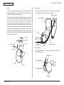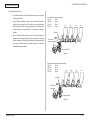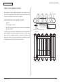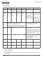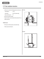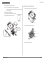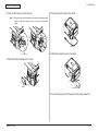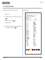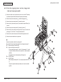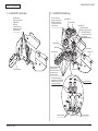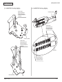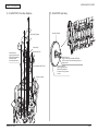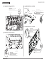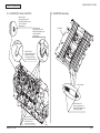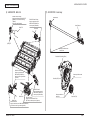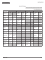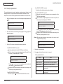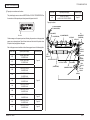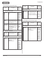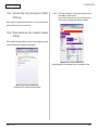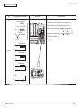
1
 C330/C530
Maintenance Manual
021712B
Copyright Information
Copyright © 2010 by Oki Data. All Rights Reserved
Disclaimer
Every effort has been made to ensure that the information in this document is complete, accurate, and up-todate. The manufacturer assumes no responsibility for the results of errors beyond its control. The
manufacturer also cannot guarantee that changes in software and equipment made by other manufacturers and
referred to in this guide will not affect the applicability of the information in it. Mention of software products
manufactured by other companies does not necessarily constitute endorsement by the manufacturer.
While all reasonable efforts have been made to make this document as accurate and helpful as possible, we
make no warranty of any kind, expressed or implied, as to the accuracy or completeness of the information
contained herein.
The most up-to-date drivers and manuals are available from the web site:
http://www.okiprintingsolutions.com
Document Revision History
Oki Data CONFIDENTIAL
Document Revision History
Rev.
No.
Date
1
2010-06-18
44346001TH Rev.1
Changed items
No.
Page
Description of change
Issue
Person in charge
Rev.
No.
Date
Changed items
No.
Page
Description of change
Person in charge
S. Ogashiwa
/
Oki Data CONFIDENTIAL
はじめに
PREFACE
This manual explains the maintenance methods for the C330dn and
C530dn printers.
The manual has been prepared for use by the maintenance personnel. For how to operate
the C330dn and C530dn printers, refer to the corresponding user’s manual.
These printer names may be given as follows in this manual.
C330dn
C330
C530dn
C530
Note!
• The contents of this manual are subject to changes without prior notice.
• Despite that exhaustive efforts were made in preparing the manual to make
it accurate, it still may contain errors. Oki Data will not hold itself liable
for any damage that results or is claimed to have resulted from repairs,
adjustment, or modifications of the printers conducted by the users using
this manual.
• The parts employed in the C330dn and C530dn printers
are so delicate that they may be damaged if not treated properly. Oki Data
Corporation highly recommends that the maintenance of the printers is
undertaken by ODC's registered maintenance personnel.
• Work after eliminating static electricity.
44346001TH Rev.1
/
CONTENTS
Oki Data CONFIDENTIAL
CONTENTS
1. CONFIGURATION...................................................................... 6
4.REPLACEMENT OF PARTS..................................................... 57
1.1 System configuration ............................................................................................. 7
4.1 Notes on replacement of parts.............................................................................. 58
1.2 Printer configuration . ............................................................................................. 9
4.2 Part replacement procedure................................................................................. 60
1.3 Optional items ...................................................................................................... 10
4.2.1 Belt unit........................................................................................................... 60
1.4 Specifications . ..................................................................................................... 11
4.2.2 Fuser unit........................................................................................................ 61
1.5 Interface specifications ........................................................................................ 13
4.2.3 Left side cover................................................................................................ 61
1.5.1 USB interface specifications .......................................................................... 13
4.2.4 Right side cover.............................................................................................. 62
1.5.1.1 USB interface overview........................................................................... 13
4.2.5 Face-up tray.................................................................................................... 62
1.5.1.2 USB interface connector and cable . ...................................................... 13
4.2.6 Rear cover...................................................................................................... 63
1.5.1.3 USB interface signals . ........................................................................... 13
4.2.7 LED assembly. and LED assembly springs.................................................... 63
1.5.2 Network interface specifications .................................................................... 14
4.2.8 Image drum fan and ZHJ board...................................................................... 64
1.5.2.1 Network interface overview..................................................................... 14
4.2.9 CU/PU PCB and low-voltage power supply.................................................... 64
1.5.2.2 Network interface connector and cable................................................... 14
4.2.10 Top cover assembly...................................................................................... 66
1.5.2.3 Network interface signals ....................................................................... 14
4.2.11 Top cover and LED head cable assembly..................................................... 66
2. DESCRIPTION OF OPERATION............................................. 15
4.2.12 Operator panel assembly............................................................................. 67
4.2.13 Board IBB and LCD...................................................................................... 67
2.1 Electrophotographic process mechanism ............................................................ 16
4.2.14 MPT assembly.............................................................................................. 68
2.2 Printing process.................................................................................................... 20
4.2.15 Front fan, hopping motor, rear fan, image drum motor and
3.INSTALLATION.......................................................................... 32
3.1 Cautions, and do’s and don’ts............................................................................... 33
3.2 Unpacking procedure . ......................................................................................... 34
3.3. Printer installation instructions ............................................................................ 35
3.4 List of components and accessories . .................................................................. 36
3.5 Assembly procedure ............................................................................................ 37
3.5.1 Assembly of the printer main unit .................................................................. 37
3.5.2 Connection of the power cable ...................................................................... 41
cover-open switch......................................................................................... 69
4.2.16 High-voltage power supply board................................................................. 70
4.2.17 Guide-ejection assembly, fuser connector assembly and
color-registration assembly.......................................................................... 71
4.2.18 Frame-MPT assembly and feeder assembly............................................... 72
4.2.19 Side-L assembly, side-R assembly and base assembly ⑦ ......................... 73
4.2.20 Feed rollers................................................................................................... 74
4.3 Locations to lubricate............................................................................................ 75
3.5.3 Installation and recognition confirmation of an option ................................... 43
3.6 Printing of MenuMap . .......................................................................................... 53
3.7 Connection methods............................................................................................. 54
3.8 Checking of paper used by the user..................................................................... 56
44346001TH Rev.1
/
CONTENTS
Oki Data CONFIDENTIAL
5. MAINTENANCE MENUS.......................................................... 87
7.5.4.2 Print operation is not possible (C330dn/C530dn only) . ....................... 193
5.1 System Maintenance menu (for maintenance personnel)..................................... 88
7.5.4.2.1 Check the OS (Operating System)................................................ 193
5.2 Maintenance Utility................................................................................................ 90
7.5.4.2.2 Has a printer been created?.......................................................... 193
5.3 User maintenance menu functions....................................................................... 92
7.5.4.2.3 Is the IPP setting set to Enable?................................................... 193
5.3.1 Maintenance menu (for end-users)................................................................. 92
7.5.4.3 A certificate cannot be created. (C330dn/C530dn only)....................... 194
5.3.2 Self-diagnostic mode...................................................................................... 93
7.5.4.3.1 Not all the required entry fields are filled in................................... 194
5.3.3 Various types of printing on stand-alone basis............................................. 110
7.5.4.3.2 The printer is printing..................................................................... 194
5.3.4 Button functions at power-on........................................................................ 111
7.5.4.4 A certificate cannot be installed. (C330dn/C530dn only).................. 194
5.4 Setup after part replacement.............................................................................. 112
7.5.4.4.1 The printer IP address has been changed. . ................................. 194
5.4.1 Notes on CU/PU board replacement............................................................ 112
7.5.4.4.2 The network card has been initialized. ......................................... 195
5.5 Manual density adjustment operation................................................................. 114
7.5.4.4.3 A CSR has been deleted............................................................... 195
5.6 Printer ADMIN MENU......................................................................................... 115
7.5.4.4.4 Install an intermediate Certificate. ................................................ 195
7.5.4.5 Other questions (C330dn/C530dn only) .............................................. 196
6. PERIODIC MAINTENANCE................................................... 118
7.5.4.5.1 Time required for creation of a certificate...................................... 196
6.1 Cleaning.............................................................................................................. 119
7.5.4.5.2 Communication time when the encryption function is enabled...... 196
6.2 LED lens array cleaning...................................................................................... 120
7.5.4.5.3 Can encrypted printing be performed without IPP?....................... 196
6.3 Pick-up roller cleaning......................................................................................... 122
7.5.4.5.4 What will happen if SSL/TLS is set to OFF after a certificate is
6.4 Pinter internal cleaning....................................................................................... 123
7.TROUBLESHOOTING............................................................. 125
7.1 Before troubleshooting........................................................................................ 126
7.2 Points to check before dealing with image troubles............................................ 126
7.3 Precautions for dealing with image troubles....................................................... 126
7.4 Preparation for troubleshooting........................................................................... 126
created (or installed)?.................................................................... 196
7.5.4.5.5 How to change the port number.................................................... 196
7.5.4.5.6 The error message “The security certificate was issued by a
company you have not chosen to trust. View the certificate to
determine whether you want to trust the certifying authority” is
displayed........................................................................................ 196
7.5.4.5.7 The error message “Name of security certificate is invalid or does
7.5 Troubleshooting procedure.................................................................................. 127
not match the site name” is displayed............................................ 197
7.5.1 LCD messages list........................................................................................ 127
7.5.4.6 Restrictions when using Internet Explore 7 (C330dn/C530dn only) . 198
7.5.2 Preparation for troubleshooting.................................................................... 148
7.5.4.6.1 Warning indication when SSL is enabled for self-signed
certificates..................................................................................... 198
7.6 Fuse check.......................................................................................................... 199
7.5.3 Troubleshooting of image problems ............................................................. 180
7.5.4 Network troubleshooting . ............................................................................ 187
7.5.4.1 Connection errors occur by use of a Web browser
(C330dn/C530dn only) ..................................................................... 187
7.5.4.1.1 Has a certificate been created?..................................................... 188
7.5.4.1.2 Is the SSL/TLS setting set to ON?................................................. 188
7.5.4.1.3 Check the version number of the Web browser............................. 189
7.5.4.1.4 Check the encryption strength of the printer.................................. 190
8. CONNECTION DIAGRAMS .................................................. 200
8.1 Resistance value checking ................................................................................ 201
8.2 Layout of parts ................................................................................................... 204
8.3 Firmware revision numbers . .............................................................................. 218
8.3.1 ROM control numbers.................................................................................. 218
8.3.2 Checking and indication of the revision number .......................................... 219
8.3.3 Stamp of maintenance board indication ...................................................... 219
44346001TH Rev.1
/
Oki Data CONFIDENTIAL
1. CONFIGURATION
1.1 System configuration .......................................................................7
1.2 Printer configuration ........................................................................9
1.3 Optional items ...............................................................................10
1.4 Specifications ................................................................................11
1.5 Interface specifications ..................................................................13
1. CONFIGURATION
Oki Data CONFIDENTIAL
1.1 System configuration
Figure 1-1-1 and Figure 1-1-2 show the system configurations of the C330dn
and C530dn printers.
Waste toner
sensor board
Operator
panel board
ID
motor
WR sensor
Registration
clutch
MPT
clutch
Rear
cover SW
EXIT
sensor
IN sensor
C LED HEAD
Duplex
rear sensor
Front
FAN
Paper
feed
motor
Hopping
sensor
Hopping
clutch
1st P.E
sensor
Density sensor
Color registration
sensor board
M LED HEAD
Duplex
front sensor
Y LED HEAD
Belt
thermistor
K LED HEAD
CU/PU board
PU
CU
Belt unit
fuse-cut
CD1
ASIC(/)
Belt unit
LAN
High-voltage
I/F
High-voltage board
K-ID
C-ID
M-ID
Y-ID
TAG
board
TAG
board
TAG
board
TAG
board
TAG I/F
Flash
ROM
EEP
ROM
Cover-open
SW
C toner
sensor
M toner
sensor
Y toner
sensor
Toner sensor board
ID
FAN
1st cassette
sensor
BELT
motor
Rear
FAN
Heater control,
others
ID UP/
DOWN sensor
nd P.E
sensor
Optional SD
memory card
(C530 only)
Option
RAM
nd TRAY PCB
nd
hopping
sensor
nd IN
sensor
Fuser
3.3V,5V,4V,0VL,0VP
Low-voltage board
ID fuse
cut
Environmental
sensor
EEP
ROM
Resident
RAM
Fuser fuse-cut/upper center/for
compensation/lower thermistor
Fuser
motor
Duplex
clutch
Shutter
solenoid
K toner
sensor
USB
CD1
ASIC(1/)
nd
paper feed
motor
Heater power
nd
registration
clutch
nd
ホッピング
クラッチ
AC-SW
Inlet
nd hopping clutch
Figure 1-1-1 System Configuration Diagram (C530/C330)
44346001TH Rev.1
/
Oki Data CONFIDENTIAL
44346001TH Rev.1
1. CONFIGURATION
/
1. CONFIGURATION
Oki Data CONFIDENTIAL
1.2 Printer configuration
The internal part of the 330dn and C530dn printers consists of the
following sections:
• Electrophotographic processing section
• Paper paths
• Controllers (CU/PU)
• Operator panel
• Power supplies (high-voltage power supply/low-voltage power supply)
Figure 1-2 shows the configuration of the printers.
Figure 1-2
44346001TH Rev.1
/
Oki Data CONFIDENTIAL
1. CONFIGURATION
1.3 Optional items
The following optional items are available
(1) Optional tray (2nd Tray)
(2) Additional memory
(3) SD memory card (C530 only)
(authentication printing, encrypted secure printing)
44346001TH Rev.1
10 /
1. CONFIGURATION
Oki Data CONFIDENTIAL
1.4 Specifications
C530dn
C330dn
Printing
system
Xerographic method using LEDs (light emitting diodes) as light sources
Resolution
600 dots/inch (LED head)
600 × 600 dpi/600 × 1200 dpi/600 × 600 dpi × 2 bits (print resolution)
Print color
Four colors of yellow, magenta, cyan, and black
CPU
Power PC
RAM
capacity
256 MB
(Max. 756 MB)
Supported
OSes
Windows Vista/
Windows Server
2008/Windows
XP/Windows
Server 2003/
Windows 2000
Japanese
Version
Mac OS 9.0
to 9.2.2, Mac
OS X 10.3.9 to
10.5 Japanese
Version
See the system
requirements
for further
information.
Print
languages
PostScript3
emulation
PCL5c/PCL XL
emulation
Internal
fonts
Interface
128 MB
(Max. 640 MB)
Windows Vista/Windows Server 2008/Windows XP/
Windows Server
2003/Windows 2000 Japanese Version
Mac OS X 10.3.9 to 10.5 Japanese Version
See the system requirements for further information.
-
C530dn
Print speed
*1
(at 600 ×
600 dpi or
600 × 1200
dpi)
Color:
26 pages/minute (A4-size plain
paper in copy mode),
10 pages/minute (postcards and
label stocks),
12 pages/minute (177g/m2 [152kg]
or more thick paper),
14 pages/minute (duplex printing
on A4 plain paper)
Monochrome:
30 pages/minute (A4 plain paper in
copy mode),
10 pages/minute (postcards and
label stocks),
16 pages/minute (duplex printing
on A4 plain paper)
C330dn
Color:
22 pages/minute (A4-size plain
paper in copy mode),
10 pages/minute (postcards and
label stocks),
12 pages/minute (189g/m2
[163kg] or more thick paper),
12 pages/minute (duplex printing
on A4 plain paper)
Monochrome:
24 pages/minute (A4 plain paper
in copy mode),
10 pages/minute (postcards and
label stocks),
13 pages/minute (duplex printing
on A4 plain paper)
USB (supporting Hi-Speed USB), 100BASE-TX/10BASE-T
44346001TH Rev.1
11 /
1. CONFIGURATION
Oki Data CONFIDENTIAL
C530dn
C330dn
Paper size
*2
A4, A5, A6, B5, Letter, Legal 13 inch, Legal 13.5 inch, Legal 14 inch,
Executive, 16K (184 × 260 mm), 16K (195 × 270 mm), 16K (197 × 273
mm), Custom, Postcard, Double-postcard, Envelope, Index Card
Paper type
*2
Plain paper (64g/m2 [55kg] to 220g/m2 [151kg]), Postcard, Envelope,
Labels
Feed type *2
Automatic feeding by Tray 1
Automatic feeding by or manual feeding from the multi-purpose tray
Automatic feeding by a second tray unit (option)
Automatic
feeding by a
second tray
unit (option)
Tray
capacity
Tray1: 280 sheets of 64g/m2 (55kg) plain paper, 25mm or less in total
thickness
Multi-purpose tray: 110 sheets of 64g/m2 (55kg) plain paper, 10mm
or less in total thickness, 40 postcards, 10
envelopes of 85g/m2 paper
Second tray unit (option): 580 sheets of 64g/m2 (55kg) plain paper, 53
mm or less in total thickness
Paper
ejection *2
Face-up (ejecting paper with the front side up)/Face-down (ejecting paper
with the back-side up)
Stacker
capacity *3
Face-up: 110 sheets of 64g/m2 (55kg) plain paper
Face-down: 150 sheets of 64g/m2 (55kg) plain paper
Assured
print area
Area excluding 6.35mm from paper edges (except special media such as
envelopes)
Print
accuracy
Print start position accuracy: ±2mm, Paper skew: ±1mm/100mm
Image expansion: ±1mm/100mm (in use of 82g/m2 of 70kg paper)
Warm-up
time
In 60 sec. after power on (25°C) *4
Within 32 sec. from power saving
Power
AC 100V ± 10%, 50/60Hz ± 2%
C530dn
C330dn
Power
consumption
*5
Operating:
Max. 1170W,
Average 540W
(25°C)
Ready:
Average 90W
(25°C)
Power save
mode:
Max. 14W
Sleep mode:
Approx. 0.9W
Inrush
current
70A or less (25°C)
Operating
environment
conditions
Operating: 10 to 32°C, 20 to 80% RH (max. wet-bulb temperature: 25°C,
max. wet- and dry-bulb temperature difference: 2°C)
Non-operating: 0 to 43°C, 10 to 90% RH (max. wet-bulb temperature:
26.8°C, max. wet -and dry-bulb temperature difference: 2°C)
Print quality
assured
conditions
30 to 73% RH at 10°C, 30 to 54% RH at 32°C, 10 to 32°C at 30% RH, 10
to 27°C at 80% RH, 17 to 27°C at 50 to 70% RH in color printing
Standard
operating
conditions
Average power–on hours: 600 hours/month
Average number of printed pages: 6,000 pages/month
Operating:
Max. 1170W,
Average 540W
(25°C)
Ready:
Average 80W
(25°C)
Power save
mode:
Max. 9.5W
Sleep mode:
Approx. 1.8W
Operating:
Max. 1170W,
Average 480W
(25°C)
Ready:
Average 90W
(25°C)
Power save
mode:
Max. 14W
Operating:
Max. 1170W,
Average 480W
(25°C)
Ready:
Average 80W
(25°C)
Power save
mode:
Max. 9.5W
Consumables, Toner cartridges, image drum units, belt units, fuser units, feed roller sets
maintenance
units
Printer life
5 years or 420,000 pages (A4)
Total weight
*6
Approx. 22kg
5 years or 300,000 pages (A4)
*1: Print speed varies depending on sizes, types and thickness of paper and paper feed
types.
*2: There are limitations on paper feed types and paper ejection types depending on
paper sizes, types and thickness.
*3: The stacker capacities may different from the specifications depending on operating
44346001TH Rev.1
12 /
1. CONFIGURATION
Oki Data CONFIDENTIAL
1.5 Interface specifications
1.5.1 USB interface specifications
((2) Cable
Length: USB 2.0 cable no more than five meters long
(two meters or less recommended)
(A shielded USB 2.0 cable shall be used.)
1.5.1.1 USB interface overview
(1) Basic specifications
USB (Hi-Speed USB supported)
1.5.1.3 USB interface signals
Signal name
(2) Transmission mode
Full speed (Max. 12 Mbps ± 0.25%)
High speed (Max. 480 Mbps ± 0.05%)
(3) Power control
Self-powered device
Function
1
Vbus
Power (+5V)
2
D-
For data transmission
3
D+
For data transmission
4
GND
Shell
Shield
Signal ground
1.5.1.2 USB interface connector and cable
(1) Connector
• Printer side:
B-receptacle (female)
Upstream port
Product equivalent to UBR24-4K5C00 (Made by ACON)
Connector pin arrangement
2
1
3
4
• Cable side: B-plug (male)
44346001TH Rev.1
13 /
1. CONFIGURATION
Oki Data CONFIDENTIAL
1.5.2 Network interface specifications
1.5.2.1 Network interface overview
1.5.2.2 Network interface connector and cable
(1) Connector
100BASE-TX/10 BASE-T (automatically switched, not usable simultaneously)
Basic specifications
Connector pin arrangement
Network protocols (*: C330dn/C530dn only)
TCP/IP spec.
1
Network layer
ARP, IP, ICMP, IPv6*, IPSec*
Transport layer
TCP, UDP
Application layer
LPR, Port9100, FTP, HTTP, HTTPS*, IPP, SNMPv1, SNMPv3*,
TELNET, DHCP/BOOTP, DNS, DDNS, WINS, UPnP, Bonjour,
SNTP, SMTP, POP*, Windows Rally (WSD Print, LLTD)
NBT/NetBEUI*:
SMB, NetBIOS, NetBIOS over TCP
(2) Cable
NetWare*:
Remote pr inter mode (maximum eight pr int ser ver s)
Print server mode (maximum eight file servers, 32 queues)
Support of encrypted passwords (in print server mode)
NetWare 6J/5J/4.1J (NDS, bindery)
SNMP
EtherTalk*:
IEEE 802.1X*:
44346001TH Rev.1
Non-shield twisted-pair cable with RJ-45 connector (Category 5 recommended)
1.5.2.3 Network interface signals
Pin No.
Signal name
Direction
Function
ELAP, AARP, DDP, AEP, NBP, ZIP, RTMP, ATP, PAP
1
TXD+
FROM PRINTER
Transmitting data +
EAP-TLS, PEAP
2
TXD-
FROM PRINTER
Transmitting data -
3
RXD+
TO PRINTER
Receiving data +
4
−
−
Not in use
5
−
−
Not in use
6
RXD-
TO PRINTER
Receiving data -
7
−
−
Not in use
8
−
−
Not in use
14 /
Oki Data CONFIDENTIAL
2. DESCRIPTION OF OPERATION
2.1 Electrophotographic process mechanism .....................................16
2.2 Printing process..............................................................................20
2. DESCRIPTION OF OPERATION
Oki Data CONFIDENTIAL
2.1 Electrophotographic process mechanism
(1) Electrophotographic process
(2) Charging
The electrophotographic process is explained briefly below:
1. Charging
A voltage is applied to the charging roller, which is placed in contact with the OPC
drum surface, to charge the OPC drum surface.
A voltage is applied to the CH roller to electrically charge the surface of the
OPC drum.
Charging roller
Power
supply unit
2. Exposure
The LED head radiates light onto the charged OPC drum surface in
accordance with an image signal. The electric charge of the radiated part
of the OPC drum surface attenuates depending on the intensity of the light,
thus forming an electrostatic latent image on the OPC drum surface.
3.
Development
Charged toner adheres to the electrostatic latent image of the OPC drum by
electrostatic power, and forms a visible image on the OPC drum surface.
4.
Transfer
Paper is placed over the OPC drum surface and an electric charge is
applied to it from the backside by the transfer roller, so that the toner image
is transferred to the paper.
5. Fusing
(3) Exposure
The light emitted from the LED head is radiated onto the charged OPC drum
surface. The charge of the radiated part of the OPC drum attenuates according to
the intensity of the light, forming an electrostatic latent image on the OPC drum
surface.
LED head
Heat and pressure are applied to the toner image on the paper to promote
its fusion.
The drum cleaning blade removes toner remaining on the OPC drum after
transfer.
- - -
OPC drum
Charging roller
6. Drum cleaning
--
Power
supply unit
LED head
--
- - -
-
--
7. Static elimination
Residual potential on the image drum is removed.
8. Belt cleaning
The belt cleaning blade removes toner remaining on the belt.
OPC drum
OPC drum
Paper
44346001TH Rev.1
16 /
2. DESCRIPTION OF OPERATION
Oki Data CONFIDENTIAL
(4) Development
(5) Transfer
A sheet of paper is placed over the OPC drum surface, and an electric charge is
given to the paper from its backside by the transfer roller.
When a high voltage is applied to the transfer roller from the power supply unit, the
charge induced on the transfer roller moves on to the surface of the paper through
the contact part between the transfer roller and the paper, and the toner is attracted
to the paper surface from the OPC drum surface.
Toner adheres to an electrostatic latent image on the drum surface, thereby turning
the electrostatic latent image into a toner image.
1. The sponge roller allows the toner to stick to the developing roller.
Charging roller
--
- - -
-
---
- - -
-
--
OPC drum
-
-
-
Sponge roller
-
Developing roller
-
Paper
OPC drum
-+ -+ -+ -+ -+ -+ -+ -+ -+ -+ -+ -+
2. The electrostatic latent image on the OPC drum surface is turned into a
visible image by the toner.
Transfer roller
-+
-+
-+
-+
-+
Transport belt
Power
supply unit
44346001TH Rev.1
17 /
2. DESCRIPTION OF OPERATION
Oki Data CONFIDENTIAL
(6) Fusing
(7) Drum cleaning
The toner image transferred on the paper is fused on the paper by heat and
pressure when the paper passes through the heat roller and the backup roller unit
(consists of a backup roller, a pat, and a fuse belt).
Waste toner area
The heat roller is heated by 800W and 300W internal halogen lamps, and the
backup roller has no internal halogen lamps and is heated by heat transferred from
the heat roller. The fuser temperature is controlled according to the temperature
that is detected with the thermistor not contacting to the heat roller surface. The
temperature detected with the other thermistor that is frictionally sliding against the
backup roller surface is used to control the fuser temperature under designated
conditions. There is also a thermostat for safety purposes. When the heat roller
temperature rises above a certain temperature, the thermostat is open and voltage
supply to the heater is cut off. The backup roller unit is pressed against the heater
by the press spring on both sides.
Toner cartridge
ID unit
Thermostat
Drum cleaning
blade
Thermistor
Paper transfer direction
Unfixed toner remaining on the OPC drum is removed by the drum cleaning blade
and collected into the waste toner area of the K toner cartridge.
Heat roller
Paper
waste toner of
waste toner path
(8) Static elimination
Backup roller
After completing transfer, the OPC drum is illuminated with its surface to reduce
static charge of its surface.
Charging roller
Pat
Static-eliminating
Fuser belt
Thermistor
Static-eliminating
OPC drum
44346001TH Rev.1
18 /
2. DESCRIPTION OF OPERATION
Oki Data CONFIDENTIAL
(9) Belt cleaning
Toner remaining on the transfer belt is scraped off by the belt cleaning blade and
collected into the waste toner box of the transfer belt unit.
Transport belt
Belt waste toner box
Belt cleaning blade
44346001TH Rev.1
19 /
2. DESCRIPTION OF OPERATION
Oki Data CONFIDENTIAL
2.2 Printing process
Paper fed from Tray 1, Tray 2 or Tray 3 is carried by the paper feed roller, the registration roller L,
and the transport roller. When paper is fed from the MPT, it is carried by the MPT paper feed roller
and the registration roller U. Then, an unfixed toner image is created on the paper transported
onto the belt sequentially through the electrophotographic process of KYMC.
Thereafter, the image is fixed under heat and pressure as the paper goes through the fuser
unit. After the image has been fixed, the paper is ejected to a face-up stacker or to a face-down
Fuser unit
Top cover
stacker, according to the outputting method selected by opening or closing of the face-up stacker.
Paper exit
The above refers to the simplex printing operation of the printers, and the following explains the
duplex printing operation.
During duplex printing, paper, which firstly passes the fuser unit after its backside is printed, is
Y
M
C
K
sucked into the duplex unit by the separator DUP. After entering the paper reverse transport path,
the paper is carried from there to the inside of the duplex unit by the inverting operation of the
Front cover
Face-up stacker
reverse roller. After passed through the duplex unit by the transport roller that is located on the
transport path inside the duplex unit, the paper is fed along the paper feed route of the duplex unit,
Paper cassette
and then arrives the route for paper feeding from a tray. From here on, the same operation as that
of simplex printing of paper fed from the tray takes place.
Second tray unit (option)
44346001TH Rev.1
20 /
2. DESCRIPTION OF OPERATION
Oki Data CONFIDENTIAL
(1) Paper fed from 1st Tray
(3) Transport belt
1. As illustrated in Figure 2-1, after the paper feed motor starts running
(clockwise) and the 1st clutch comes ON, the paper is fed from the 1st Tray.
1. As the transport belt motor runs in the direction of the arrow, the transport
belt is driven. The belt unit consists of one transpor t roller placed
immediately underneath each color drum, with a transport belt inserted in
between them.
2. After causing the IN sensor to come ON, the paper is further carried over a
certain distance to finally hit the registration roller. (This corrects skew of the
paper.)
3. It causes the registration clutch to come ON and has the registration roller
carry the paper.
(2) Paper fed from MPT
1. As illustrated in Figure 2-1, after the paper feed motor starts running
(clockwise) and the MPT clutch comes ON, the paper is fed from the MP
Tray.
As the specified voltage is applied, the transport belt and the transport
rollers carry the paper on the transport belt to the fuser unit as transferring
the toner images present on each color drum to the paper.
Drum
2. After causing the IN sensor to come ON, the paper is further carried over a
certain distance to finally hit the registration roller. (This corrects skew of the
paper.)
3. It causes the registration clutch to come ON and has the registration roller
carry the paper.
Y
M
C
K
MPT clutch
Paper feed roller
Transport roller
Transport belt
IN sensor
Transport belt roller
Registration roller
Paper feed
from the MPT
Figure 2-2
WR sensor
Paper feed motor
Registration clutch
1st clutch
Paper feed sensor
Paper feed roller
Separation roller
Paper feed from
the 1st clutch
Figure 2-1
44346001TH Rev.1
21 /
2. DESCRIPTION OF OPERATION
Oki Data CONFIDENTIAL
(4) Up/down-motions of ID units
1. The up/down motions of the ID units take place driven by the fuser motor
and the up/down clutch.
2. Figure 2-3 shows the motions of each of the ID units when the printer is
operated for color printing. As the lift-up motor runs (counterclockwise)
with the up/down clutch ON, the lift-up link slides to the left causing the ID
units to come down as shown in Figure 2-3. In that state, color printing is
available.
3. Figure 2-4 shows the motions of each of the ID units when the printer is
operated for monochrome printing. As the lift-up motor runs (clockwise)
with the up/down clutch ON, the lift-up link slides to the right causing the ID
units, except the K-ID unit, to go up as shown in Figure 2-4. In that state,
monochrome printing is available.
ID unit motions during color printing
Y-ID unit
Down
M-ID unit
Down
C-ID unit
Down
K-ID unit
Down
Y-ID
M-ID
C-ID
K-ID
Lift-up link
Fuser motor
(counterclockwise)
Up/down clutch
Figure 2-3
ID unit motions during monochrome printing
Y-ID unit
Lift up
M-ID unit
Lift up
C-ID unit
Lift up
Y-ID
K-ID unit
Down
M-ID
C-ID
K-ID
Lift-up link
Fuser motor
(clockwise)
Up/down clutch
Figure 2-4
44346001TH Rev.1
22 /
2. DESCRIPTION OF OPERATION
Oki Data CONFIDENTIAL
(5) Ejection unit and paper ejection
(a) Face-down ejection
Face-down ejection is available when the face-up tray is closed.
In that state, the separator FU is fixed in the direction illustrated in Figure
Eject roller (drive)
Face-up tray
detection sensor
Fuser unit
2-5, and the face-up tray detection sensor is enabled.
Heat roller (drive)
As the fuser motor runs (counterclockwise), the eject rollers and the heat
roller start rotating, and printed paper is ejected with its face down.
(b) Face-up ejection
Face-up ejection is available when the face-up tray is open.
In that state, the separator FU is fixed in the direction illustrated in Figure
Separator FU
Fuser motor
(counterclockwise)
2-6, and the face-up tray detection sensor is disabled.
As the fuser motor runs (clockwise), the eject rollers and the heat roller
start rotating, and printed paper is ejected with its face up. (When face-up
ejection is enabled, duplex printing is not available.)
Figure 2-5
Face-up tray
detection sensor
Eject roller (drive)
Fuser unit
Heat roller (drive)
Separator FU
Fuser motor
(clockwise)
Figure 2-6
44346001TH Rev.1
23 /
2. DESCRIPTION OF OPERATION
Oki Data CONFIDENTIAL
(6) Duplex printing system (paper flipping and returning to the paper feed route)
1. In a cer tain period of time after the fuser motor star ts running
counterclockwise and the rear end of paper being fed passes the eject
sensor, the fuser motor starts running clockwise. (It changes from the state
shown in Figure 2-7 to the state shown in Figure 2-8.)
2. As a result of that, the eject rollers start rotating in the reverse direction, and
the paper is flipped and carried to the duplex unit.
3. When the duplex unit clutch becomes on, the paper is transferred by the
duplex unit transport rollers.
4. In a certain period of time after the rear end of the paper passes the eject
rollers, the fuser motor starts running counterclockwise, and as a result of
this, the eject rollers can carry the next paper to the exit. (It changes from
the state shown in Figure 2-8 to the state shown in Figure 2-7.) (The duplex
unit transport rollers rotate in the same direction regardless of the running
direction of the motor.)
5. The paper that is carried by the duplex unit transport rollers comes back to
the route for paper feeding from a tray. After that, the paper is handled in the
same way as paper fed from a tray for simplex printing.
Eject roller (drive)
Fuser unit
Heat roller (drive)
Fuser motor (counterclockwise)
Eject sensor
Duplex unit clutch
Duplex unit transport roller
Figure 2-7
Eject roller (drive)
Fuser unit
Heat roller (drive)
Eject sensor
Fuser motor (clockwise)
Duplex unit clutch
Duplex unit transport roller
Figure 2-8
44346001TH Rev.1
24 /
2. DESCRIPTION OF OPERATION
Oki Data CONFIDENTIAL
(7) Cover-opening motions of the color registration sensor and the density sensor
1. As illustrated in Figure 2-9, when the solenoid is energized, the link lever
moves, causing the cover of the color registration sensor and the density
sensor to open.
2. As the solenoid is de-energized, the spring pushes the cover, causing the
cover of the color registration sensor and the density sensor to close.
Color registration sensor
Density sensor
Spring
Link lever
Solenoid
Figure 2-9
44346001TH Rev.1
25 /
2. DESCRIPTION OF OPERATION
Oki Data CONFIDENTIAL
Outline of color registration correction
Color registration is corrected by reading correction patterns, which are printed on the belt,
by use of the color registration sensor located inside the sensor shutter under the belt unit.
Transport belt
The sensor is used to detect patterns and correct color registration.
Automatic start timing of color registration correction
• At power-on
• When an opened cover is closed
• When 400 or more pages have been printed or at least six hours has passed after
the previous correction
A correction error may be issued due to an inadequate toner amount of a pattern generated,
a sensor stained with toner, deficient opening/closing of the shutter, or for other reasons.
However, even if such a registration correction error is issued, it is not indicated on the
operator panel. Therefore, it is necessary to perform forcible color registration correction in
the self-diagnostic mode (Section 5.3.2.6) to check the error indication.
Belt waste toner box
Sensor shutter
Color registration sensor
Belt cleaning blade
Density sensor
Right color registration correction pattern
Left color registration correction pattern
Color registration sensor
44346001TH Rev.1
26 /
Oki Data CONFIDENTIAL
2. DESCRIPTION OF OPERATION
Error checking methods and remedies
The color registration correction test function among the other self-diagnostic functions is
employed to check errors. (Section 5.3.2.6)
Remedies for different errors
• CALIBRATION (L or R), DYNAMICRANGE (L or R)
Check 1: If the above indication appears, check the connected state of the sensor
cable.
If the connected state is found abnormal, restore it to the normal state.
Check 2: Check to see whether the sensor surface is stained with toner, paper dust
or any other foreign matter.
If it is found stained, wipe it clean.
Check 3: Check to see whether the sensor shutter opens and closes normally, by
the MOTOR & CLUTCH TEST of the self-diagnostic function. If the shutter
operates imperfectly, replace the shutter unit.
If no problem was found by the checks 1 through 3, there is a problem with
the circuit.
Replace each of the color registration sensor board, the CU/PU board and
the connector cable one by one and check that no error will occur again.
• BELT REFLX ERR
Check 4: If this indication appears, check the cleaned state for the toner remaining
on the belt surface, in addition to making the above checks 1, 2 and 3.
Take out the belt unit, turn the drive gear located on the left rear side, and
ensure that the belt surface has been cleaned thoroughly.
If cleaning is not achieved perfectly and there still remains toner on the belt
surface after the drive gear has been turned, replace the belt unit.
• (Y or M or C) LEFT, (Y or M or C) RIGHT, (Y or M or C) HORIZONTAL
Check 5: If the above indication appears, check to see whether toner of NG-issuing
color is running short.
Replace a toner cartridge, as needed.
44346001TH Rev.1
27 /
2. DESCRIPTION OF OPERATION
Oki Data CONFIDENTIAL
Outline of density correction
Density is corrected by reading correction patterns, which are printed on the belt, by use of
the density sensor located inside the sensor shutter under the belt unit.
Transport belt
Automatic start timing of density correction:
• When the environment at power-on is drastically different from the environment of the
previous correction
• When one or more of four ID count values at power-on indicates that the corresponding
IDs are almost new
Belt waste toner box
• When an ID count after the previous correction exceeds 500
• When one or more ID is replaced with a new one
• When the belt is replaced with a new one
• When a toner low or toner empty error is cleared by a replacement of a toner cartridge
in a toner low or toner empty state
A correction error may be issued due to an inadequate toner amount of a pattern generated,
a sensor stained with toner, deficient opening/closing of the shutter, or for other reasons.
However, even if such a density correction error is issued, it is not indicated on the operator
panel. Therefore, it is necessary to perform forcible color registration correction in the selfdiagnostic mode (Section 5.3.2.7) to check the error indication.
44346001TH Rev.1
Sensor shutter
Density sensor
Belt cleaning blade
Density sensor
Density correction pattern
28 /
2. DESCRIPTION OF OPERATION
Oki Data CONFIDENTIAL
Error checking methods and remedies
Principle of toner sensor detection
The density correction test function among the other self-diagnostic functions is employed to
check errors. (Section 5.3.2.7)
Remedies for different errors
Shielding plate
Prism
• CALIBRATION ERR, DENS SENSOR ERR
Check 1: If the above indication appears, check the connected state of the sensor
cable.
If the connected state is found abnormal, restore it to the normal state.
Check 2: Check to see whether the sensor surface is stained with toner, paper dust
or any other foreign matter.
If it is found stained, wipe it clean.
If no problem was found by the checks 1 and 2, there is a problem with the circuit.
Replace each of the density sensor, the CU/PU board and the connector cable one
by one and check that no error will occur again.
• DENS SHUTTER ERR
Check 3: Check to see whether the sensor shutter opens and closes normally, by
the MOTOR & CLUTCH TEST of the self-diagnostic function. If the shutter
operates imperfectly, replace the shutter unit.
Toner LOW is detected by a toner sensor (Reflection sensor) installed inside each of the
printers. A shielding plate is mounted inside each ID and rotates in synchronization with toner
agitation.
Moreover, each ID has a shutter fitted. Each shutter is synchronized with the operation lever
of the relevant toner cartridge, and the toner sensor can detect that the toner cartridge has
been loaded properly. Detection may not take place normally, and a toner sensor error may
be issued, if a shielding plate or toner sensor is stained with toner, or if an ID unit and the
relevant toner sensor do not remain exactly opposite to each other in their positions.
Principle of the toner counter
After image data is developed to binary data that the printers can print, the LSI counts the
data as the number of print dots. The amount of toner consumed is calculated from that count
value, and the remaining amount of toner is thus indicated. As opposed to this, toner LOW
detection by a toner sensor is implemented when the amount of toner remaining inside an ID
unit physically decreases to below a certain level.
• DENS ID ERR
Check 4: Take out the ID units and examine them to see if the drum surface has any
abnormal toner smudge.
Replace the LED head (out-of-focus), or replace any ID units with any abnormality.
To test-operate a new ID unit, use the Fuse Keep Mode of the maintenance menu.
44346001TH Rev.1
Principles of ID, belt, and fuser counters
ID counter: One count represents the value that results from dividing the amount
of rotation of a drum by three when three A4-size sheets are printed
continuously.
Belt counter: One count represents the value that results from dividing the amount
of rotation of the belt by three when three A4-size sheets are printed
continuously.
Fuser counter: One count is registered when paper is shorter than the length of
Legal 13-inch paper. When paper is longer than that, a count to add is
determined by the number of times that the Legal 13-inch paper length is
exceeded. (Rounding up of decimal fractions)
29 /
2. DESCRIPTION OF OPERATION
Oki Data CONFIDENTIAL
Counter specifications
Total page count
MPT page count
Tray 1 page count
Tray 2 page count
Color page count
Monochrome page count
Description
Total number of
prints
Number of print media
hopped from MPT
Number of print media
hopped from Tray 1
Number of print media
hopped from Tray 2
Total number of color prints
Total number of monochrome prints
Count method:
A4-basis or size
independence
Count up after
passing the writing
sensor
Count up if MPF (MPT)
hopping is finished
successfully
Count up if Tray 1
hopping is finished
successfully
Count up if Tray 2
hopping is finished
successfully
The number of print media passing
the fuser in color mode is counted
when each job is finished (1*).
The value is counted on an A4/
Letter basis. Refer to A4/Letter
conversion table (on the next page).
The number of print media passing
the fuser in monochrome mode is
counted when each job is finished
(1*).
Printing speed for color mode
may be applied to monochrome
mode. The value is counted on an
A4/Letter basis. Refer to A4/Letter
conversion table (on the next page).
peration when paper Printed pages are not counted when a paper feed (hopping) jam or a feed jam (380) occurs.
Printed pages are counted when any jam except the said jams occurs.
has jammed
Since the total page count is incremented when the front end of print media passes the writing
sensor, a feed jam (380) is also included into the limits on counts according to its jam type.
If paper jams before passing the fuser, its pages are not counted. If
paper jams after passing the fuser, its pages are counted.
Operation for
Duplex
The count increases by two.
If a color page and a monochrome page exist in a pair of two pages,
the color page count increases by one, and the monochrome page
count increases by one. If a pair of two pages is in color, the color page
count increases by two. If a pair of two pages is in monochrome, the
monochrome page count increases by two.
Reset condition
Value storage
destination
Menu/MenuMap
output
EngineMenuMap
output
Front/back count
(+2)
Only front count (+1)
None
PU
None
PU
PU
(1) Replacement of ROM with another one of a different version
(2) Change of the shipping destination
(3) Execution of MENU RESET of the system maintenance menu
(4) Replacement of a CU board
PU
CU
CU
−
−
(*2)
(*3)
(*3)
(*3)
*1. Each of the count is updated at the end of each job or each of four pages; however, the count is not updated if the power is turned off when any page from page one through page three of a job of four or more pages is being printed.
*2. It is shown in the header of MenuMap.
*3. EngineMenuMap outputs Engine Menu Print (the first page) and Engine EEPROM Dump Print (the last page), and the number of sheets of paper fed from each tray is described only in
the latter one (DUMP page only).
44346001TH Rev.1
30 /
2. DESCRIPTION OF OPERATION
Oki Data CONFIDENTIAL
A4/Letter conversion table
Each count shall increase, in relation to every sheet of paper, by the values in the table below.
Paper size
Simplex
Duplex
LETTER
1
2
EXECUTIVE
1
2
LEGAL14
1
2
LEGAL13.5
1
2
LEGAL13
1
2
A4
1
2
A5
1
2
A6
1
-
B5
1
2
COM-9
1
-
COM-10
1
-
MONARCH
1
-
DL
1
-
C5
1
-
Postcard
1
-
Double-postcard
1
-
Custom
1
2
Custom, Length > 210 mm
2
4
Custom, Length ≥ 900 mm
4
-
Envelope (Choukei 3)
1
-
Envelope (Choukei 4)
1
-
Envelope (Youkei 4)
1
-
1
-
Envelope (Envelope A4)
INDEXCARD
44346001TH Rev.1
31 /
Oki Data CONFIDENTIAL
3. INSTALLATION
3.1 Cautions, and do’s and don’ts........................................................33
3.2 Unpacking procedure ....................................................................34
3.3. Printer installation instructions . ....................................................35
3.4 List of components and accessories .............................................36
3.5 Assembly procedure . ....................................................................37
3.6 Printing of MenuMap .....................................................................53
3.7 Connection methods.......................................................................54
3.8 Checking of paper used by the user...............................................56
3. INSTALLATION
Oki Data CONFIDENTIAL
3.1 Cautions, and do’s and don’ts
Warning
• Do not install the printer in any potentially high-temperature location or a near heat
source.
• Do not install the printer in a location where chemical reaction may occur (laboratory
and the like).
• Do not install the printer in the proximity of inflammable solvents, such as alcohol and
paint thinner.
• Do not install the printer within reach of children.
• Do not install the printer on an unstable surface (e.g., on a rickety bench or on a
slanting place).
• Do not install the printer in a location with moisture or heavy dust, or in direct sun.
• Do not install the printer in an environment with sea wind or corrosive gas.
• Do not install the printer in a location with heavy vibration.
• In the event that the printer is inadvertently dropped or its cover is damaged, remove
the power plug from the power outlet and contact the customer center.
Such mishap could lead to an electric shock, fire or injury.
• Do not connect any power cord, printer cable or ground wire in any other manner than
the way specified in the manual. Failure to observe the above could result in fire.
• Do not stick in an object into the vent hole.
Such action could lead to an electric shock, fire or injury.
• Do not place a glass filled with water or the like on the printer.
Such action could lead to an electric shock or fire.
• When the printer cover is opened, be careful not to touch the fuser unit.
It may cause burns.
• Do not throw the toner cartridges or the image drum cartridges into fire.
Dust explosion could cause burns.
• Do not use a highly combustible spray near the printer.
It may case a fire because the printer contains parts that get extremely hot.
• In the event that the cover becomes unusually hot, emits smoke, bad smell, or
abnormal noise, remove the power plug from the power outlet and contact the
customer center.
It may lead a fire.
44346001TH Rev.1
Warning
• If water or any other liquid enters the inside of the printer, remove the power plug from
the power outlet and contact the customer center.
Fire could break out.
• If someone drops foreign objects such as a clip in the printer, remove the power plug
from the outlet and take out the foreign objects.
It may cause an electric shock, fire, or injury.
• Do not operate or disassemble the printer in any other manner than the way specified
in the manual.
Failure to observe this warning could result in an electric shock, fire or injury.
Caution
• Do not install the printer in a location where its vent hole is blocked.
• Do not install the printer directly on a shag carpet or rug.
• Do not install the printer in a sealed room or other location with poor ventilation or
permeability.
• Make sure to ventilate sufficiently when continuously using the printer in a small room
for a long time.
• Install the printer away from a strong magnetic field or noise source.
• Install the printer away from a monitor or TV.
• To move the printer, hold both sides of them.
• The printer, which weighs approximately 25 kg (packed), should be lifted by two or
more people.
• While the printer power is on or the printer is printing, do not come close to the paper
exit. Such action could lead to injury.
When the precautionary notes concerning the installation and operation are explained, the
user should be referred to the precautionary notes given in the user's manual. Especially, give
thorough explanation on the power cord and the ground wire.
33 /
3. INSTALLATION
Oki Data CONFIDENTIAL
3.2 Unpacking procedure
Warning
Personal injury may occur.
Since the printer weights approximately 25 kg (packed), it should be lifted by two or
more people.
44346001TH Rev.1
34 /
3. INSTALLATION
Oki Data CONFIDENTIAL
3.3. Printer installation instructions
• Install the printer in a location where the following temperature and humidity are met:
Ambient temperature
: 10 to 32°C
Ambient humidity
: 20 to 80 % RH (relative humidity)
Maximum wet-bulb temperature
: 25°C
Plan view
0cm
• Exercise caution to avoid dew condensation.
• If the printer is installed in a location with ambient relative humidity below 30%, use a
humidifier or antistatic mat.
100cm
60cm
Installation space
0cm
• Place the printer on a flat desk large enough to accommodate its footings.
• Provide enough spaces around the printer.
Side view
70cm
44346001TH Rev.1
35 /
3. INSTALLATION
Oki Data CONFIDENTIAL
3.4 List of components and accessories
• Check to make sure that the components are free from damage, dirt or other irregularities in their appearance.
• Ensure that none of the accessories to the components is missing and that they are
free from breakage or other flaw.
• If any irregularity is discovered, contact the user management section for instructions.
Warning
Personal injury may occur.
The printer weights approximately 31 kg (or 36 kg when packed), so it should be lifted
by two or more people.
Software CD-ROM
Power cord
Warranty card and user registration card
User’s manual (Setup and usage)
User’s manual (CD-ROM)
Quick Guide
Bag for Quick Guide
Note! No printer cable is supplied with the printer.
Printer (main unit)
Image drum cartridges (one each of cyan, magenta, yellow, and black installed in
the printer)
Inform the user that the toner cartridges and image drum cartridges can be separated
one from the other.
44346001TH Rev.1
36 /
3. INSTALLATION
Oki Data CONFIDENTIAL
3.5 Assembly procedure
3.5.1 Assembly of the printer main unit
(3) Remove the four protective sheets.
Setup of the printer
(1) Remove the protective tapes (six places) from the surface of the printer.
Protective sheet
Paper
Protective tape
Paper
Protective tape
(2) Press the OPEN button to open the top cover.
Protective tape
(4) Remove the stopper release (orange) while pushing down the lever (blue) of the
fuser unit in the direction of the arrow .
Note! The stopper release is used when the printer is not used for a long time or
being transported. Be sure to keep it.
Lever (blue) of the fuser unit
OPEN button
Stopper release
(orange)
44346001TH Rev.1
37 /
3. INSTALLATION
Oki Data CONFIDENTIAL
(5) Slide the locks of the (four) toner cartridges to the left to lock the toner cartridges.
Lock (blue)
Loading paper in the paper cassette
(1) Pull out the paper cassette.
Note!
Do not remove the rubber from the plate.
(2) Adjust the paper stopper and the paper guide to the size of the paper to be loaded
and fix them firmly.
Paper stopper
(6) Close the top cover.
Plate
Paper guide
(3) Fan the edges of paper stack and align the edges of the stack on a level surface.
44346001TH Rev.1
38 /
3. INSTALLATION
Oki Data CONFIDENTIAL
(4) Load the paper with the print side facing down.
Loading paper in the multi-purpose tray
Note! • Place the paper against the front side of the paper cassette.
(1) Open the multi-purpose tray and also the paper supporter.
• Do not allow the level of paper to pass the “ ” mark of the paper guide (530
sheets of 70 kg paper).
(5) Hold the paper with the paper guide.
(6) Turn the paper size dial to the size of the paper loaded.
Paper loading orientation
(7) Insert the paper cassette back into the printer.
マルチパーパストレイ
(2) Move the manual feed guide to the paper size.
Place the print side
facing down.
手差しガイド
マルチパーパストレイ
mark
用紙サポータ
手差しガイド
(3) Align the edges of the paper stack.
44346001TH Rev.1
39 /
3. INSTALLATION
Oki Data CONFIDENTIAL
(4) Insert the paper, print-face up, along the manual feed guide straight as far as it will
go.
Storing Quick Guide
Stick a bag for Quick Guide on the printer to store Quick Guide.
(1) Remove double-faced tapes (two places) from the back of the bag.
mark
Insert the paper, print-face up,
straight as far as it will go.
Double-faced tape
Note! Do not allow the level of paper to pass the ““ ”” mark of the paper guide (100
sheets of 70 kg paper, or 10 envelopes).
(2) Stick the bag for Quick Guide on the printer.
Quick Guide
(5) Press the set button.
Set button
Vents
Bag for Quick Guide
Note! Stick the bag to a place not to block the vents on the printer.
44346001TH Rev.1
40 /
3. INSTALLATION
Oki Data CONFIDENTIAL
3.5.2 Connection of the power cable
Power supply conditions
Connecting the power cord
Note! Ensure that the power switch is OFF (O).
(1) Insert the power cord into the printer.
• Observe the following conditions:
AC
: 100V ± 10%
Power frequency : 50 Hz or 60 Hz ± 2 Hz
• If the available power is unstable, use a voltage regulator or the like.
• The maximum power consumption of this printer is 1,170W. Ensure that the power
source offers an ample margin in the power capacity.
• Proper operation with a UPS (uninterruptible power supply) is not guaranteed. A
warning to not use a UPS should be given to the user.
Warning
It may cause an electric shock or fire.
• Installation and removal of the power cord and the ground wire must be performed after
turning the switch to OFF.
• The ground wire should be connected to a dedicated ground terminal. If it is not possible to
establish a ground, consult the dealer where the user bought this printer.
• Never connect the ground wire to a water pipe, gas pipe, or a telephone line ground, or to
a lightning rod or the like.
• Be sure to complete connection to the ground terminal before inserting the power plug into
the power outlet. Also be sure to remove the power plug from the power outlet before disconnection
from the ground terminal.
• Hold the power plug of the power cord to plug in or unplug the cord.
• Insert the power plug securely into a receptacle as far as it will go.
• Do not insert or remove the power plug with wet hands.
• Lay the power cord in a location where it is not likely stepped on, and avoid placing
anything on the power cord.
• Do not bundle or tie the power cord.
• Do not use a damaged power cord.
• Avoid many loads on one electrical outlet.
• Do not connect the printer to the same power outlet shared by other electric appliances.
Especially, if the printer is connected to the same power outlet in conjunction with an airconditioner, copy machine or shredder, electric noise may cause false operation of the printer. If it
is inevitable to connect them to the same power outlet, use a commercial noise filter or noise-cut
transformer.
• Use the power cord that is supplied with this printer and insert it directly into an outlet. For
this printer, do not use a power cord provided for any other product.
• Do not use an extension cord. If it is inevitable to use an extension cord, use one with
rating of 15A or more.
• Use of an extension cord may hinder the printer from operating normally because of an AC
voltage drop.
• Do not turn off the power or disconnect the power plug while the printer is printing.
• If the printer is going to be placed out of use for an extended period of time due to a long
spell of holidays or travel, unplug the power cord.
• Do not use the supplied power cord for other products.
About the connections of the power cord and the ground wire, the user should be given
thorough explanation by referred to the user's manual.
44346001TH Rev.1
(2) Connect the ground wire to a ground terminal of a power outlet.
Warning
It may cause an electric
shock.
Be sure to use the ground wire.
Ground terminal
Ground wire
(3) Inset the power plug into the power outlet.
Pressing on (I) of the power switch
[Ready to Print] will appear when the printer has started up completely.
Note! An error (of code 126, 171, 175, 177, or 320) may occur if the printer is
turned on when it is cold. In such a case, turn off the printer, wait for a while
and turn it on again.
41 /
3. INSTALLATION
Oki Data CONFIDENTIAL
No use for a long time
Turning off the power
Note! Turning off the power without taking proper shutdown steps may damage and
disable the printer. Be sure to follow the steps below.
(1) Check that [CMYK] or [ONLINE] is displayed on the operator panel. If the printer is
in sleep mode, press the [POWER SAVE/RESTORE] button to make [CMYK] or
[ONLINE] displayed.
(2) Press the
button repeatedly until [Shutdown menu] appears.
button. By pressing the
Press the
button after [Shutdown Start Execute]
appears, the shutdown process will start.
Advise the user to unplug the power cord if the printer will not be used for a long time,
such as during long vacations or travel. In addition, instruct the user to attach the stopper
release to the fuser unit.
Note! Before disconnecting the ground terminal, disconnect the power plug from the
power outlet.
Note! This printer does not cause any malfunction even if the power plug is
disconnected for a long time (four weeks or longer). Unwarranted deterioration
of consumables of the printer, including toner and image drums, should be
informed to the user.
(3) After [PLEASE POW OFF SHUTDOWN COMP] appears, press the power switch
OFF ( ).
44346001TH Rev.1
42 /
3. INSTALLATION
Oki Data CONFIDENTIAL
3.5.3 Installation and recognition confirmation of an option
(1) Installation of an optional tray (second tray) unit
An optional tray unit is intended for increasing the amount of paper that can be loaded in the
printer. An optional tray holds 580 sheets of 55 kg paper, allowing the printer to print up to
970 sheets continuously when used with a standard paper cassette and a multi-purpose tray
together.
2. Place the printer on an optional tray unit.
Note! The printer weights approximately 22 kg. It should be lifted by two or more
people.
❶ Align the holes in the bottom of the printer to the pins of the optional tray unit.
❷ Place the printer gently on the optional tray unit.
Type: TRY-C4E1
Hole in the bottom of the printer
Post
1. Turn off the printer and disconnect the power cord and the printer
cable.
3. Attach lock pieces to the printer.
Lock piece
Turn off the printer by following the steps described under “Turning off the power” in
section 3.5.2.
Note! • Turning off the power without taking proper shutdown steps may cause a
failure of the printer, so be sure to execute the shutdown menu.
• Installation of an optional tray unit with the power on may cause a failure of
the printer.
Lock piece
44346001TH Rev.1
43 /
Oki Data CONFIDENTIAL
1. CONFIGURATION
1.3 Optional items
The following optional items are available:
(1) Optional tray (2nd Tray)
(2) Additional memory (C530 only)
(3) SD memory card (C530 only)
(authentication printing, encrypted secure printing)
44346001TH Rev.1
10 /
1. CONFIGURATION
Oki Data CONFIDENTIAL
1.2 Printer configuration
The internal part of the 330dnn, and C530dn printers consists of the
following sections:
• Electrophotographic processing section
• Paper paths
• Controllers (CU/PU)
• Operator panel
• Power supplies (high-voltage power supply/low-voltage power supply)
Figure 1-2 shows the configuration of the printers.
Figure 1-2
44346001TH Rev.1
/
3. INSTALLATION
Oki Data CONFIDENTIAL
5. Loosen the screw and remove the bracket.
2. Remove the connector cover.
Screw
Connector cover
Bracket
Lock
6. Insert an additional memory into the slot and push it against the
main unit.
3. Remove the printer cable.
Note! • Do not touch electronic parts or connector terminals.
• Install the memory by observing the correct orientation of it. The memory
has a notch in its edge so as to fit with the memory slot connector.
Printer cable
7. Attach the bracket and tighten the screw.
4. Touch the metal part of the printer to discharge static.
Metal part
Screw
Bracket
44346001TH Rev.1
46 /
3. INSTALLATION
Oki Data CONFIDENTIAL
8. Connect the printer cable to the printer.
Printer cable
9. Attach the connector cover to the printer.
11. Print the configuration repor t and check the printout for
successful installation of the additional memory.
❶ Print the configuration report by following the steps instructed in section 3.6.
❷ Check the total memory size shown at “Total Memory Size” in the header.
Note! Reinstall the additional memory if the size at “Total Memory Size” is not
correct.
Connector cover
10. Connect the power cord to the printer and turn the power ON.
Note! If the operator panel displays [SERVICE CALL 031: ERROR], remove the
memory and reinstall it.
44346001TH Rev.1
47 /
3. INSTALLATION
Oki Data CONFIDENTIAL
(3) Installation of an SD card (C530dn only)
3. Remove the printer cable.
Note! Fonts cannot be downloaded to any SD
cards for C530dn.
SD cards are provided as an option for C530dn.
• SD memory card (model name: SDC-A1)
It is a storage added to C530dn printers. It is used for authenticated printing, print
job saving and buffer printing, or used when [Collating Error] appears in making
collated sets of copies.
Printer cable
4. Touch the metal part of the printer to discharge static.
1. Turn off the printer and disconnect the power cord.
Turn off the printer by following the steps described under “Turning off the power” in
section 3.5.2.
Note! • Turning off the power without taking proper shutdown steps may cause a
failure of the printer, so be sure to execute the shutdown menu.
• Installation of an SD card with the power on may cause a failure of the
printer.
Metal part
2. Remove the connector cover.
5. Loosen the screw and remove the bracket.
Connector cover
Lock
Screw
Bracket
44346001TH Rev.1
48 /
3. INSTALLATION
Oki Data CONFIDENTIAL
6. Insert an SD memory card into the slot.
8. Connect the printer cable to the printer.
Note! • SD memory cards are not usable when the safety switch against possible
erasure is in the active position, so be sure to move it to the inactive
position.
Printer cable
SC memory card
9. Attach the connector cover to the printer.
7. Attach the bracket and tighten the screw.
Screw
Bracket
Connector cover
10. Connect the power cord to the printer and turn the power ON.
44346001TH Rev.1
49 /
3. INSTALLATION
Oki Data CONFIDENTIAL
11. Print the configuration report and check the printout for
successful installation of the SD memory card.
12. Set up SD Memory Card in the printer driver.
Note! Administrator privileges on the computer are required.
For Windows PS printer driver
❶ For Windows Vista, select [Star t] [Control Panel] and click [Printers].
For Windows XP, select [Start] - [Control
Panel] - [Printers and Other Hardware]
- [Printers and Faxes].
❶ Print the configuration report by following the steps instructed in section 3.6.
❷ Check that the memory size is shown at “SD Memory Card.”
MemoThe size of SD memory cards may be different from the above example.
Note! Reinstall the SD memory card if its size is not shown there.
For Windows Server 2003, select [Start]
- [Printers and Faxes].
For Windows 2000, select [Star t] [Settings] - [Printers].
❷ Right-click the [C530 (PS)] icon and
select [Properties].
❸ Click [Get pr inter infor mation] in
Subsequently, it is required to make settings in the printer driver to have the SD memory card
recognized by the printer driver.
If the printer driver hasn’t been set up, set up the printer driver by referring to the relevant
user’s manual (Setup) and then perform the following setup by taking steps described on the
following pages.
[Installable Options] on the [Device
Settings] tab, and click [Setup] or
[Obtain printer information]. For USB
connection, manually specify [Installed]
for [SD Memory Card].
❹ Click [OK].
44346001TH Rev.1
50 /
3. INSTALLATION
Oki Data CONFIDENTIAL
For Windows PCL / PCL XPS Printer Driver
❶ For Windows Vista, select [Start] [Control Panel] and click [Printers].
For Windows XP, select [Start] - [Control
For Macintosh
In Macintosh, when options are added before installation of the printer driver, device information can be automatically obtained. When options are added after installation of the
printer driver, make setting of options according to the following steps.
Panel] - [Printers and Other Hardware]
- [Printers and Faxes].
For Windows Server 2003, select [Start]
- [Printers and Faxes].
For Windows 2000, select [Star t] [Settings] - [Printers].
Network connection
❶ Select the printer in [Chooser] and click
[Reconfigure].
❷ Click [Configuration].
❷ Right-click the [C530 (**)] (** is PCL or
❸ Select [Installed] for [SD Memory Card]
PCL XPS, which is a type of the printer
driver) icon and select [Properties].
and click [OK].
❹ Close [Chooser].
❸ Select [Obtain printer information] on
the [Device Options] tab. For USB
connection, check the [SD Memory
Card] checkbox manually.
❹ Click [OK].
For USB connection
❶ Drag the printer icon to the trash on the desktop and empty the trash.
❷ Using the Desktop Printer Utility, create a desktop printer again. When a desktop
printer is created again, the settings are updated.
Memo For how to create the desktop printer, see “Creating the Desktop Printer” of
“Setup for Macintosh with USB Connection” in the user’s manual.
44346001TH Rev.1
51 /
3. INSTALLATION
Oki Data CONFIDENTIAL
For Mac OS X
In Mac OS X, if options are added before installation of the printer driver, device information
can be automatically obtained, but when connected via IP Print or Bonjour (Rendezvous),
device information cannot be obtained automatically.
Also, when connected via AppleTalk, device information cannot be obtained automatically
if options are added after installation of the printer driver.
In the above cases, you need to set up options according to the following steps.
❶ Double-click [Application] - [Utilities] [Printer Setup Utility] in the hard disk.
❷ Select [C530], click [Show Info] and
open [Printer Info].
❸ Select [Installable Options].
❹ C h e c k t h e [ S D M e m o r y C a r d ]
checkbox and click [Apply Changes].
❺ Close [Printer Info].
❻ Check that the name of the added
printer is in [Printer List] and then close
[Print Center].
44346001TH Rev.1
52 /
3. INSTALLATION
Oki Data CONFIDENTIAL
3.6 Printing of MenuMap
Print MenuMap to check to make sure that the printer operates correctly.
(C530dn MenuMap sample)
(1) Load A4 paper in a tray.
(2) Press the
the
button several times until [Information Menu] appears, and then press
button.
(3) After MenuMap Print appears, press the
button.
Printing of MenuMap is started.
MemoTo print Network Information (two pages), press the
until [Network] appears, and then press the
44346001TH Rev.1
button following step (2)
button.
53 /
3. INSTALLATION
Oki Data CONFIDENTIAL
3.7 Connection methods
<USB connection>
Note! Refer to the user’s manual for operating environment.
Connecting the computer to the printer
(1) Plug the USB cable into the USB interface connector of the printer.
(2) Plug the USB cable into the USB interface connector of the computer.
Preparing a USB cable
Note! Be careful not to plug the USB cable into the network interface connector.
Such wrong connection could cause malfunction.
Note! • No printer cable is supplied with the printer. Ask the user to prepare a USB
2.0 printer cable.
• When connection is to be made in “High-Speed” mode with a USB 2.0, use
a Hi-Speed-ready USB 2.0 cable.
• A USB 2.0 cable to be used must be no more than five meters long. A USB
cable of two meters or less is recommended.
Cover
Switching off the printer and the computer
MemoAlthough a USB cable can be plugged in or unplugged with the computer and
the printer switched on, for secure installation of the USB driver and the printer
driver to be performed subsequently, the printer should be turned off.
Hook
USB interface connector
Cover
Memo For the setup procedure of the printer driver, see the user’s manual.
44346001TH Rev.1
54 /
3. INSTALLATION
Oki Data CONFIDENTIAL
<Ethernet cable connection>
Switching off the printer and the computer
Note! Refer to the user’s manual for operating environment.
Connecting the computer to the printer
(1) Plug the Ethernet cable into the network interface connector of the printer.
Preparing an Ethernet cable
(2) Plug the Ethernet cable into the hub.
Note! An Ethernet cable and a hub are not supplied with the printer. Ask the user to
prepare an Ethernet cable (a Category 5 twisted pair cable, straight through)
and a hub.
<Ethernet cable>
<Hub>
Cover
Network interface
connector
Hook
Cover
Memo For the setup procedure of the printer driver, see the user’s manual.
44346001TH Rev.1
55 /
3. INSTALLATION
Oki Data CONFIDENTIAL
3.8 Checking of paper used by the user
Load the media used by the user in the printer, make media weight/media type setting, print
out MenuMap/Demo Page, and check printouts to make sure that no toner flakes off.
Settings on the operator panel
Type
Media weight
Printer driver
(paper
[Media weight]
Media weight
thickness)
settings*2
(paper thickness)
Media type
(paper type)*1
Weight or thickness
Plain
paper*3
55 64kg (64 74g/m2)
2
65 70kg (75 82g/m )
71 89kg (83 104g/m2)
2
90 103kg (105 120g/m )
Light
MEDIUMLIGHT
Medium Light
MEDIUM
Medium
HEAVY
PLAIN
Heavy
104 151kg
(121 176g/m2)
ULTRAHEAVY1
Ultra heavy 1
152 189kg
(177 220g/m2)
ULTRAHEAVY2
Ultra heavy 2
Postcard*4
4
Envelope*
Label
LIGHT
—
—
—
—
—
—
—
—
0.1 to under 0.17 mm
HEAVY
Label 1
LABELS
0.17 to 0.2 mm
ULTRAHEAVY1
Label 2
*1:The factory default for the media type is [PLAIN].
*2:Media weight and type can be set on the operator panel and in the printer driver. The
settings in the printer driver take priority. Data is printed out in accordance with the
settings on the operator panel when [Auto selection] is selected in [Feed tray] or when
[Printer setting] is selected in [Media weight].
*3:The weight of paper supported for duplex print is 64 to 176g/m2 (55 to 151 kg).
*4:It is not necessary to set media weight and type for postcards and envelopes.
MemoPrint speed decelerates when [MEDIUM] through [ULTRAHEAVY2] of media
weight or [LABELS] of media type is set.
44346001TH Rev.1
56 /
Oki Data CONFIDENTIAL
4. REPLACEMENT OF PARTS
This chapter describes the procedures of the field replacement of parts, assemblies and units. The procedures are to detach them. Reverse
the procedures to attach them.
and
) do not identical to the part numbers in the maintenance disassembly
The reference part numbers used in this manual (such as
configuration diagram (44346007TL) and RSPL (44346007TR) for the manual.
4.1 Notes on replacement of parts.......................................................58
4.2 Part replacement procedure...........................................................60
4.3 Locations to lubricate.....................................................................75
4.REPLACEMENT OF PARTS
Oki Data CONFIDENTIAL
4.1 Notes on replacement of parts
(1) Prior to replacing a part, unplug the AC cord and the interface cable.
(2) Do not disassemble the printer so long as it operates properly.
Turn off the printer [the power switch to the off (O) position].
(3) Minimize disassembly. Do not detach parts not shown in the part replacement
procedure.
Pull out the AC plug of the AC cord from the AC power source.
(4) Use the replacement tools specified.
Remove the ground wire.
(5) Conduct disassembly in the order instructed, or part damage may occur.
Unplug the AC cord and the interface cable.
(6) Removed small parts, such as screws or collars, should be tentatively installed in
their original positions.
(a) Be sure to use the following procedure to unplug the AC cord:
Warning
Electric shock hazard
When replacing the low-voltage power supply, electric shock may occur. Wear insulated
gloves, or be careful not to touch the conductors or terminals of the power supply directly.
After the AC cord is unplugged, the capacitor may take about one minute to discharge
completely or, due to PCB breakdown, could not discharge. Use caution about electric
shock.
(7) Do not use static-prone gloves when handling integrated circuits (ICs), including
microprocessors, and ROM and RAM chips, or circuit boards.
(8) Do not place printed-circuit boards (PCBs) directly on the printer or a floor.
(b) Always use the following procedure to reconnect the printer:
Connect the AC cord and the interface cable to the printer.
Connect the ground wire.
Insert the AC plug into the AC power source.
Turn on the printer [the power switch to the on (I) position].
Unplugging
Plugging
44346001TH Rev.1
58 /
4.REPLACEMENT OF PARTS
Oki Data CONFIDENTIAL
Table 4-1-2 shows the tools necessary to use Maintenance Utility software.
Maintenance Tools:
Table 4-1-1 shows the tools necessary to replace printed-circuit boards and units:
No.
Table 4-1-1: Maintenance Tools
No.
Maintenance Tool
Quantity
1
Phillips
screwdriver with
magnetic tip, No.
2-200
1
2
Screwdriver No.
3-100
1
3
Screwdriver No.
5-200
1
4
Digital multimeter
1
5
Pliers
1
6
Handy vacuum
cleaner (toner
vacuum)
1
7
E-ring pliers
1
Table 4-1-2: Maintenance Tools
Use
Remarks
1
3- to 5-mm
screws
Maintenance Tool
Notebook
personal
computer (with
Maintenance
Utility software
installed)
Quantity
1
2
USB cable
1
3
Ethernet cable
(crossover cable)
1
Use
Remarks
See section
5.2 for
Maintenance
Utility.
See note.
E-shaped ring
removal
Note! Use a toner vacuum. Using a general-purpose vacuum may cause fire.
44346001TH Rev.1
59 /
4.REPLACEMENT OF PARTS
Oki Data CONFIDENTIAL
4.2 Part replacement procedure
This section describes the procedure for replacing the parts and assemblies shown in the
disassembly diagrams below.
(3) Turn the (two blue) lock handles of the belt unit ② in the direction of the arrows
and, holding the unit by the (blue) handle, detach the unit.
4.2.1 Belt unit
Lock lever (blue)
(1) Open the top cover.
(2) Remove the image drum unit ① .
top cover
Lock lever (blue)
Note! Cover the removed image drum cartridges with a piece of black paper.
black paper
44346001TH Rev.1
60 /
4.REPLACEMENT OF PARTS
Oki Data CONFIDENTIAL
4.2.2 Fuser unit
4.2.3 Left side cover
(1) Open the top cover.
(1) Open the top cover.
(2) Pull the (blue) fuser unit lock lever in the direction of the arrow and detach the fuser
unit ① .
(2) Remove the two (silver-colored) screws ① .
(3) Unlatch and detach the left side cover ② .
Top cover
Fuser unit lock lever (blue)
Fuser unit lock lever (blue)
Feeder unit
44346001TH Rev.1
61 /
4.REPLACEMENT OF PARTS
Oki Data CONFIDENTIAL
4.2.4 Right side cover
4.2.5 Face-up tray
(1) Open the face-up tray ① in the direction of the arrow and, warping it, disengage
two portions to detach the face-up tray.
(1) Open the top cover.
(2) Remove the cassette assembly.
(3) Remove the interface cover ① .
(4) Loosen the screw ② to remove the memory cover ③ .
(5) Open the MPT assembly ④ .
(6) Remove the two (black) screws ⑤ and one (silver-colored) screw ⑥ .
(7) Unlatch two portions A and B to detach the right side cover ⑦ .
Latch B
MPT Assy
Latches A
44346001TH Rev.1
62 /
4.REPLACEMENT OF PARTS
Oki Data CONFIDENTIAL
4.2.6 Rear cover
4.2.7 LED assembly. and LED assembly springs
(1) Remove the left side cover and the right side cover.
(2) Remove the three (silver-colored) screws ① .
(3) Unlatch two portions A with a flat-blade screwdriver.
(4) Unlatch three portions B to slide the rear cover ② in the direction of the arrow C to
detach it.
(1) Open the top cover.
(2) Remove the cables of the LED assembly. As shown in diagram (2), apply force in
the direction of the arrow to unlatch the portion A and then the portion B to detach
the LED assembly ① .
(3) Turning the LED assembly springs ② clockwise, detach it.
Top cover
Latch A
Latches A
Latch A
Diagram (1)
C
Diagram (2)
Latch B
Latches A
44346001TH Rev.1
63 /
4.REPLACEMENT OF PARTS
Oki Data CONFIDENTIAL
4.2.8 Image drum fan and ZHJ board
(1) Remove the left side cover.
(2) Remove the (silver-colored) screw ① and the two (silver-colored) screws to detach
the image drum fan ③ .
(3) Remove the (silver-colored) screw ④ and unlatch five portions to detach the ZHJ
board ⑤ .
4.2.9 CU/PU PCB and low-voltage power supply
Warning
Electric shock hazard
When replacing the low-voltage power supply, electric shock may occur. Wear insulated
gloves, or be careful not to touch the conductors or terminals of the power supply directly.
After the AC cord is unplugged, the capacitor may take about one minute to discharge
completely or, due to PCB breakdown, could not discharge. Use caution about electric shock.
(1) Remove the right side cover.
(2) Remove the four (silver-colored) screws ① and unlatch and remove the plate shield
assembly ② .
(3) Remove all the CU/PU board cables.
(4) Remove the three (silver-colored) screws ③ to detach the PU/CU PCB ④ .
(5) Remove all the low-voltage power supply cables.
(6) Remove the two (silver-colored) screws ⑤ .to detach the low-voltage power supply
Note! The LED head cables
⑥.
should be attached, the
end of the Film-FG being
placed inside the Plateside-R so as that they
touch no sheet metal
edges of the Plate-side-R.
Exit cable wound one
turn around core
Exit connector
Fuser connector
Rear fan connector
44346001TH Rev.1
64 /
Oki Data CONFIDENTIAL
44346001TH Rev.1
4.REPLACEMENT OF PARTS
65 /
4.REPLACEMENT OF PARTS
Oki Data CONFIDENTIAL
4.2.10 Top cover assembly
4.2.11 Top cover and LED head cable assembly
(1) Remove the left side cover, the right side cover and the rear cover.
(1) Demount the top cover assembly.
(2) Remove the plate shield assembly and then the LED head cables.
(2) Remove the 18 (black) screws ① to detach the top cover ② .
(3) Remove the two screws ① to remove the plate-rear ② .
(3) Remove the (silver-colored) screw ③ to detach the LED head cable assembly ④ .
(4) Remove the (silver-colored) screw ③ and then the two E-shaped retainer rings ④
to detach the top cover ⑤ .
1
×
44346001TH Rev.1
66 /
4.REPLACEMENT OF PARTS
Oki Data CONFIDENTIAL
4.2.12 Operator panel assembly
4.2.13 Board IBB and LCD
(1) Remove the right side cover and plate shield assembly.
(1) Remove the operator panel assembly.
(2) Remove the cable of the operator panel assembly.
(2) Unlatch the three portions A.
(3) Detach the Board IBB ① .
* CU/PU PCB OPWE connector
(3) Remove the two screws ① to detach the operator panel assembly ② .
(4) Unlatch the two portions B.
(5) Detach the LCD assembly ② .
44346001TH Rev.1
67 /
Oki Data CONFIDENTIAL
4.REPLACEMENT OF PARTS
4.2.14 MPT assembly
(1) Remove the cassette assembly.
(2) Open the MPT assembly ① .
(3) Pull the MPT assembly in the direction of the arrow and release the two supports to
detach the MPT assembly.
44346001TH Rev.1
68 /
4.REPLACEMENT OF PARTS
Oki Data CONFIDENTIAL
4.2.15 Front fan, hopping motor, rear fan, image drum
motor and cover-open switch
(1) Remove the left side cover, the right side cover, the rear cover, the MPT assembly,
the plate-rear, the plate shield assembly and the operator panel assembly.
(2) Remove the two (silver-colored) screws ① to detach the hopping motor ② .
(3) Remove the two (silver-colored) screws ③ to detach the rear fan.
(4) Remove the two (silver-colored) screws ④ and unlatch the frame-MPT-side ⑤ to
remove it.
(5) Remove the two (silver-colored) screws ⑥ to detach the front fan ⑦ .
(6) Remove the four (silver-colored) screws ⑧ and the (FG) screw ⑨ to remove the
plate support ⑩ , the AC inlet ⑪ , the shaft ⑬ and the switch ⑭ .
Air
(7) Remove the four (silver-colored) screws ⑮ to detach the image drum motor ⑯ .
(3) Remove the screw to detach the cover-open switch.
Note!
• Observe the orientation to attach the low-voltage fan ⑥ .
• Be sure of the AC input voltage setting to attach the low-voltage power supply ③ .
100V : Attach a short plug to connector CN6.
230V : Attach no short plug to connector CN6.
• The low-voltage power supply ③ and the AC inlet assembly ⑤ . should
be replaced combined (they have been qualified to a safety standard,
combined).
• The number of screws varies depending on the fusing motor:
Three : 43963301 (Sanyo)
Four : 43070601 (Nidec)
• While removing or installing FAN ⑦,⑲, do not press impeller of the FAN ⑦,
⑲.
In case of the impeller unfastened by mistake, do not reuse it and install a
new FAN.
44346001TH Rev.1
Air
69 /
Oki Data CONFIDENTIAL
4.REPLACEMENT OF PARTS
4.2.16 High-voltage power supply board
(1) Remove the right side cover and the CU/PU PCB.
(2) Remove the four (silver-colored) screws ① to remove the film-PUCU board ② and
the plate board ③ .
(3) Remove the two (silver-colored) screw to remove the plate-FG ⑤ .
(4) Unlatch the four portions to detach the high-voltage power supply board ⑤ .
44346001TH Rev.1
70 /
Oki Data CONFIDENTIAL
4.REPLACEMENT OF PARTS
4.2.17 Guide-ejection assembly, fuser connector
assembly and color-registration assembly
(1) Remove the left side cover, the right side cover, the rear cover and the top cover
assembly.
(2) Remove the CU/PU PCB and the low-voltage power supply.
(3) Detach the guide-ejection assembly ① .
(4) Remove the two (silver-colored) screws ② to detach the fuser connector assembly
③.
(5) Remove the film-PUCU board ④ and the film-power board ⑤ .
(6) Remove the (silver-colored) screw ⑧ to remove the image drum fan assembly ⑦ .
(7) Remove the two (silver-colored) screws ⑥ to remove the cover-beam ⑨ and the
plate-beam ⑩ .
(8) Remove the three (silver-colored) screws ⑪ to remove the two torsion springs ⑫
and then the cover-code ⑬ .
(9) Remove the four (silver-colored) screws to detach the color-registration assembly ⑮.
44346001TH Rev.1
71 /
Oki Data CONFIDENTIAL
4.REPLACEMENT OF PARTS
4.2.18 Frame-MPT assembly and feeder assembly
(1) Remove the left side cover, the right side cover, the rear cover, the hopping motor,
the plate shield assembly, the operator panel assembly, the cover-open switch and
the frame-MPT-side.
(2) Remove the RGSNS, HPSNS and MPC cables of the PU/CUPCB.
(3) Remove the two (silver-colored) screws ① to remove the plate-front ② .
(4) Remove the two (silver-colored) screws ③ and the (black) screw ④ and unlatch the
two portions to detach the frame-MPT assembly.
(5) Remove the three (silver-colored) screws ⑥ to detach the feeder assembly
44346001TH Rev.1
72 /
Oki Data CONFIDENTIAL
4.REPLACEMENT OF PARTS
4.2.19 Side-L assembly, side-R assembly and base
assembly ⑦ .
(1) Remove the left side cover, the right side cover, the rear cover, the top cover
assembly, the operator panel assembly, the feeder assembly, the guide-ejection
assembly and the registration assembly.
(2
Remove the four (silver-colored) screws ① to remove the plate-bottom ② .
(3) Remove the E-shaped retainer ring ③ and then the shaft ④ .
(4) Remove the six (silver-colored) screws ⑤ to detach the side-L assembly ⑥ , the
side-R assembly ⑦ and the base assembly ⑧ .
44346001TH Rev.1
73 /
Oki Data CONFIDENTIAL
4.REPLACEMENT OF PARTS
4.2.20 Feed rollers
(1) Remove the cassette.
(2) Unlatch the feed rollers ① .
Latch
44346001TH Rev.1
74 /
4.REPLACEMENT OF PARTS
Oki Data CONFIDENTIAL
4.3 Locations to lubricate
This section shows the locations to lubricate. The other locations must not be lubricated.
Lubrication is not required during assembly or disassembly, except that, after lubricant is
wiped off locations, the appropriate lubricant specified must be applied to the locations.
Each number circled, accompanied with the number and name of a drawing indicates that
the lubrication work with the number is specified in the drawing.
Lubrication work
(1) Lubricant notations and names
EM-30L: Molykote EM-30L (part number 44498501)
HP-300: Molykote HP-300
PM: Pan motor oil 10W-40 or ZOA 10W-30
GE-334C: FLOIL GE-334C (part number 41823301)
SF-133: HANARL SF-133
(2) Grease boundary samples
Class
S
Amount applied (cc) 0.0005
W(mm)
1.24
A
B
C
D
E
F
0.003
0.005
0.01
0.03
0.05
0.1
2.25
2.67
3.37
4.86
5.76
7.26
Sample
W
44346001TH Rev.1
75 /
4.REPLACEMENT OF PARTS
Oki Data CONFIDENTIAL
① -1 44452301PA Side-R Assy.
① -2 44452301PA Side-R Assy.
EM-30LP Class Bx2
Apply a normal amount of
MOLYKOTE (EM-30LP)
to the whole circle of 2 places
EM-30LP Class Bx4
Apply a normal amount of
MOLYKOTE (EM-30LP)
to the whole circle of 4places
Gear-Idle-Belt
Gear-Reduct-Liftup-A
Gear-Liftup-D
Gear-Reduct-Belt
Bush-FU
Plate-BF-Caulking
44346001TH Rev.1
EM-30LP Class Bx4
Apply a normal amount of
MOLYKOTE (EM-30LP)
to the whole circle of
4places
EM-30LP Class C
Apply a normal amount of
MOLYKOTE (EM-30LP)
to the whole circle of
hatched areas.
(Shaft end surface side).
Grease prohibition
Plate-BF-Caulking
EM-30LP Class C
Apply a normal amount of
MOLYKOTE (EM-30LP)
to the whole circle of hatched
areas. (Shaft end surface
side).
76 /
4.REPLACEMENT OF PARTS
Oki Data CONFIDENTIAL
① -3 44452301PA Side-R Assy.
EM-30LP Class C
Apply a normal amount
of MOLYKOTE
(EM-30LP)
to the whole circle of
hatched areas. (Shaft
end surface side).
① -4 44452301PA Side-R Assy.
EM-30LP Class B x2
Apply a normal amount of
MOLYKOTE (EM-30LP)
to the whole circle of gear
teeth (2 places).
Gear-Reduct-FU
Gear-Idle-FUA
Gear-Idle-FUB
EM-30LP Class B
Apply a normal amount of
MOLYKOTE (EM-30LP)
to the whole circle of gear
teeth (2 places).
Gear-Idle-Exit-A
Gear-Planet
Gear-Liftup-A
Motor-DC-FU
Gear-Idle-Exit-A
Plate-BF-Caulking
EM-30LP Class B Apply
a normal amount of
MOLYKOTE (EM-30LP)
to the whole circle of
gear teeth (2 places).
EM-30LP Class B Apply a
normal amount of MOLYKOTE
(EM-30LP) to the whole circle
of gear teeth (2 places).
Grease prohibition
44346001TH Rev.1
Gear-Idle-DUP
Grease prohibition
Grease prohibition
77 /
4.REPLACEMENT OF PARTS
Oki Data CONFIDENTIAL
① -5 44452301PA Side-R Assy.
① -6 44452301PA Side-R Assy.
EM-30LP Class A
Apply a small amount of MOLYKOTE
(EM-30LP) to the hatched areas.
EM-30LP Class C
Apply a normal amount of MOLYKOTE (EM-30LP)
to the whole circle of hatched areas (Shaft end
eurface side).
Link-Liftup-R
EM-30LP Class C
Apply a normal amount of MOLYKOTE
(EM-30LP)
to the gear tooth tops.
EM-30LP Class A
Apply a small amount of MOLYKOTE
(EM-30LP) to the hatched areas.
Plate-Gear-Caulking
Gear-Reduct-ID
EM-30LP Class A
Apply a small amount of MOLYKOTE
(EM-30LP) to the hatched areas.
Grease prohibition
EM-30LP Class A
Apply a small amount of MOLYKOTE
(EM-30LP) to the hatched areas.
EM-30LP Class C
Apply a normal amount of
MOLYKOTE (EM-30LP)
to the whole circle of gear teeth (4
places).
44346001TH Rev.1
Gear-Idle-IDS
78 /
4.REPLACEMENT OF PARTS
Oki Data CONFIDENTIAL
② 44452401PA Side-L Assy.
③ 44452601PA Sensor Assy.-Regist
EM-30LP Class A
Apply a small amount of MOLYKOTE
(EM-30LP) to the hatched areas.
Plate-Position-Caulking
Frame-Shutter
EM-30LP Class C
Apply a normal amount of MOLYKOTE
(EM-30LP)
to the gear tooth tops.
Rack-L
EM-30LP Class A
Apply a small amount of MOLYKOTE
(EM-30LP) to the hatched areas.
EM-30LP Class B
Apply a normal amount of MOLYKOTE (EM-30LP) to the
hatched areas (bearing portion).
EM-30LP Class A
Apply a small amount of MOLYKOTE
(EM-30LP) to the hatched areas.
44346001TH Rev.1
79 /
4.REPLACEMENT OF PARTS
Oki Data CONFIDENTIAL
④ -1 44452701PA Front Assy.-Reg/Hop
④ -2 44452701PA Front Assy.-Reg/Hop
EM-30LP Class A
Apply a normal amount of MOLYKOTE
Note :1
(EM-30LP) to the hatched areas.
(Side of roller and ditch of shaft)
(The other side is also the same. : Two
places in total)
EM-30LP Class C
Apply a normal amount of
MOLYKOTE (EM-30LP) to
the hatched areas (Shaft end
surface side).
Shaft-Idle-Dup
Roller-Pitch
Roller-Pressure
EM-30LP Class B
Apply a normal amount of
MOLYKOTE (EM-30LP) to the
hatched areas (Center of shaft).
Shaft-Idle-Dup
Roller-Pitch
Roller-Regist
Note :1
Note :1
Frame-Regist
EM-30LP Class C
Apply a normal amount of
MOLYKOTE (EM-30LP) to
the hatched areas (Shaft end
surface side).
Grease prohibition
44346001TH Rev.1
80 /
4.REPLACEMENT OF PARTS
Oki Data CONFIDENTIAL
④ -3 44452701PA Front Assy.-Reg/Hop
④ -4 44452701PA Front Assy.-Reg/Hop
EM-30LP Class C
Apply a normal amount of
MOLYKOTE (EM-30LP) to
the hatched areas (Shaft end
surface side).
Plate-Feed-A_Caulking
EM-30LP Class C
Apply a normal amount of
MOLYKOTE (EM-30LP) to
the hatched areas (Shaft).
Shaft-Roller-Feed
Plate-Feed-A_Caulking
EM-30LP Class C
Apply a normal amount of
MOLYKOTE (EM-30LP) to
the hatched areas (Shaft end
surface side).
Roller-Feed
EM-30LP Class C
Apply a normal amount of
MOLYKOTE (EM-30LP) to
the hatched areas (Shaft).
Plate-Feed-B_Caulking
44346001TH Rev.1
81 /
4.REPLACEMENT OF PARTS
Oki Data CONFIDENTIAL
④ -5 44452701PA Front Assy.-Reg/Hop
⑤ 44364101PA Eject Assy
Plate-Feed-B_Caulking
Gear-Idle_Exit(Z3)
Gear-Idle-Z35
EM-30LP Class C
Apply a normal amount of
MOLYKOTE (EM-30LP) to
the hatched areas
(Post end surface side).
Gear-Idle-MPT-Z35
EM-30LP Class C
Apply a normal amount of MOLYKOTE (EM30LP) to surface of the post (bearing portion), the
flange portions.
Gear-Reduction-MPT-Z37-0
EM-30LP Class B x4
Apply a normal amount of
MOLYKOTE (EM-30LP) to
the whole circle of gear teeth.
Of 4pcs
Frame Assy.-Regist
44346001TH Rev.1
82 /
4.REPLACEMENT OF PARTS
Oki Data CONFIDENTIAL
⑥ -1 44453001PA Printer Unit-PX750
⑥ -3 44453001PA Printer Unit-PX750
EM-30LP Class C
Apply a normal amount of MOLYKOTE
(EM-30LP) to the hatched areas.
Plate-Assy.Side R
Spring-Torsion-L
Spring-Torsion-R
Cover-Top-Assy
Panmotoroil Class C
Apply a normal amount of Panmotoroil to
the portion of the slot of solid
coiling of this torsion-spring using a brush.
(2places)(Atbothsides)
⑥ -4 44453001PA Printer Unit-PX750
EM-30LP Class C
Apply a normal amount of MOLYKOTE
(EM-30LP) to the end face of Plate-L.
(hached areas)
⑥ -2 44453001PA Printer Unit-PX750
Plate-Assy.Side L
EM-30LP Class C
Apply a normal amount of MOLYKOTE
(EM-30LP) to the hatched areas.
44346001TH Rev.1
EM-30LP Class C
Apply a normal amount of MOLYKOTE
(EM-30LP) to the end face of Plate-L.
(hached areas)
Plate-L
83 /
4.REPLACEMENT OF PARTS
Oki Data CONFIDENTIAL
⑥ -5 44453001PA Printer Unit-PX750
⑦ 44452501PA Base-Assy
EM-30LP Class C
Apply a normal amount of
MOLYKOTE (EM-30LP) to the
end face of Plate-R.
(hatched areas)
EM-30LP Class C
Apply a normal amount of
MOLYKOTE (EM-30LP) to the
end face of Plate-R.
(hatched areas)
Plate-Base
EM-30LP Class C
Apply a normal amount of
MOLYKOTE (EM-30LP)
to the sliding surface with
Drum Shaft. (hatched areas)
Roller-Feed-Dup
EM-30LP Class C x4
Apply a normal amount of
MOLYKOTE (EM30LP) to the
hatching areas (Shaft)
GE-334C Class C
Apply a normal amount of
FLOIL (GE-334C) to
contact portion (4 places).
44346001TH Rev.1
Plate-L
84 /
4.REPLACEMENT OF PARTS
Oki Data CONFIDENTIAL
⑧ 44458601PA Belt-Unit
⑨ 44381001PA Fuser-Assy
EM-30LP Class A x8pcs
Apply a small amount of MOLYKOTE
(EM30LP) to the inside of BearingTR(Belt).
(Both sides, total 8 places)
Cam-Release
EM-30LP Class C x2pcs
Apply a normal amount of
MOLYKOTE (EM30LP) to
bearin portion (Both side).
Roller-TR
Lever-Release
Roller-Idle
Spring-TR
Grease prohibition at the
Cam-R area.
Plate-Side R-Caulking (Fuser)
EM-30LP Class B
Apply a normal amount of
MOLYKOTE (EM30LP) to
the whole circle of gear teeth
(2 places).
Roller-Drive
Grease prohibition at the
post.
Gear-Idle-(Z35)
EM-30LP Class C
Apply a normal amount of
MOLYKOTE (EM30LP) to
bearin portion (Both side).
GE-334C Class C
Apply a normal amount of FLOIL
(GE-334C) to bearin portion (2 places).
Grease prohibition to
the Gears.
Gear-Idle-(Z1)
Roller-Drive
EM-30LP Class B
Apply a normal amount of MOLYKOTE (EM30LP)
to the whole circle of gear teeth (2 places).
44346001TH Rev.1
85 /
4.REPLACEMENT OF PARTS
Oki Data CONFIDENTIAL
⑩ -1 44453701PA Cover-Assy.-Rear
⑪ 44359201PA Frame-Assy.-MPT
EM-30LP Class B
Apply a normal amount of MOLYKOTE (EM-30LP) to
the hatched areas. (Center of shaft)
SF-133 Class B
Apply a normal amount of HANAL (SF-133)
to the hatched areas.
Stacker-FU_Base
Hatched areas
Leave it for about 3 minutes (drying time) after painting HANAL SF-133, and then
assemble the Cover-Assy.-Stacker.
⑩ -2 44453701PA Cover-Assy.-Rear
Note:1
Cover-Rear
Roller-Pitch
Note:1
Shaft-Idle-Dup
Spring-Torsion-Pitch
Note:1 EM-30LP Class A
Apply a normal amount of
MOLYKOTE (EM-30LP) to the
hatched areas.
(Side of roller and ditch of shaft)
(The other side is also the same. :
Two places in total)
Hatched areas
SF-133 Class B
Apply a normal amount of HANAL (SF-133)
to the hatched areas.
44346001TH Rev.1
Shaft-Idle Dup
Roller-Pitch
86 /
Oki Data CONFIDENTIAL
5. MAINTENANCE MENUS
C330dn & C530dn can be adjusted by using Maintenance Utility, or button operation on its operator panel.
The printer has maintenance menus in addition to general menus. The menus intended for adjustment purposes should be selected.
5.1 System Maintenance menu (for maintenance personnel)..............88
5.2 Maintenance Utility.........................................................................90
5.3 User maintenance menu functions.................................................92
5.4 Setup after part replacement........................................................112
5.5 Manual density adjustment operation...........................................114
5.6 Printer ADMIN MENU...................................................................115
5. MAINTENANCE MENUS
Oki Data CONFIDENTIAL
5.1 System Maintenance menu (for maintenance personnel)
By turning on each printer while holding down
and , its System Maintenance menu is
started. The menu is displayed only in English irrespective of the destination of the printer.
Note: The menu allows for changes such as the printer’s destination changes, and is
transparent to end-users of the printer.
Category Item (1st Line)
Value
DF
(2nd Line)
CONFIG
MENU
CODESET
TYPE1
TYPE2
*
TEST
PRINT
MENU
TEST PRINT
MENU
ENABLE
DISABLE
*
FUSE
KEEP
MODE
FUSE KEEP
MODE
EXECUTE
-
PERSONALITY
(Only
C530dn)
IBM 5577
ENABLE
DISABLE
*
Table 5-1: Maintenance menu display table
Category Item (1st Line)
Value
DF
(2nd Line)
Function
SYSTEM
MAINTE
ENTER
PASSWORD
****** ****** 000 Enters a password to enter the System
000 Maintenance menu. The default for this item is
000000. Six to 12 alphanumeric characters can
be entered for the item.
OKIUSER
OKIUSER
ODA
OEL
APS
JP1
JPOEM1
OEMA
OEML
MAINTENANCE
MENU
*
Sets a destination.
JPOEM1: OEM in Japan
OEMA: A4-default Overseas OEM
OEML: Letter-default Overseas OEM
The printer automatically reboots after this
menu is exited.
Display condition:
The security SD card function is disabled.
SD CARD
FORMAT
(Only C530)
EXECUTE
-
Initializes an SD card. When executed, this
menu is exited and starts initializing an SD card.
Display condition:
The printer has the SD card installed on it
(ADMIN MENU-FILE SYS MAINTE-SD CARD
is set to ENABLE).
FLASH
FORMAT
EXECUTE
-
Displays the following confirmation message in
response to the press of the OK button:
ARE YOU SURE?
YES/NO
NO restores the previous menu display when
selected. When selected, YES exits this menu,
starting formatting the installed resident (onboard) flash device.
* Never use this item.
MENU RESET
44346001TH Rev.1
EXECUTE
-
Resets the information in the EEPROM to
factory default settings. The printer automatically
reboots after change to the default settings.
* This does not initialize some special items.
IBM PPR III XL
ENABLE
DISABLE
*
EPSON FX
ENABLE
DISABLE
*
HP-GL/2
ENABLE
DISABLE
*
Function
Displayed for all the destinations of the printer.
TYPE1: Disables Russian, Grease and
Bulgarian (language file downloading). This
value uses English for the operator panel
language when the printer already has any of
the three languages downloaded.
TYPE2: Enables Russian, Grease and
Bulgarian.
The printer automatically reboots after this
menu is exited. The default for this item is
TYPE2 when the printer's destination is OEL/
APS/OEMA, and TYPE1 when it is not OEL/
APS/OEMA.
Sets whether or not to display PRT CHK PATN
and ENG STATUS PRINT in the USER MENUPRINT INFORMATION category. This item
always does not display PRT ID CHK PATN or
ENG STATUS PRINT when set to DISABLE.
When this menu is exited after change of the
setting for the item, the printer restarts.
Places the printer online after a command is
issued from the CU to PU by pressing the OK
button. With the printer turned on, consumables
of the printer can be replaced with new ones,
and then the printer can be checked for proper
operation (where, not breaking the new ones’
fuses, the printer adds no operation counts
to the life of the consumables replaced with
the new ones). Turning off the printer ends the
check mode. Turning it on next time disables the
mode.
Does not allow USER MENU-SYS CONFIG
MENU-PERSONALITY to display PDL
languages for which DISABLE is set with
this menu. When receiving print data in such
languages, the printer displays INVALID
DATA, discarding the data. When the printer's
destination is Japan and IBM PPR III XL and
EPSON FX is set to ENABLE, no operation of
the printer is assured.
88 /
5. MAINTENANCE MENUS
Oki Data CONFIDENTIAL
Category Item (1st Line)
Value
DF
(2nd Line)
-
CHANGE
PASSWORD
Function
Changes a password. Pressing the OK button
for this menu displays NEW PASSWORD and
VERIFY PASSWORD, allowing for entry of a
new password.
NEW
PASSWORD
****** ****** -
Sets a new password to enter the System
Maintenance menu. Six to 12 alphanumeric
characters can be entered for this item.
VERIFY
PASSWORD
****** ****** -
Prompts a user to verify and enter again
the new password that was set for NEW
PASSWORD to enter the System Maintenance
menu. Six to 12 alphanumeric characters can
be entered for this item.
ENGINE
DIAG
MODE
44346001TH Rev.1
-
Enters the engine self-diagnostic mode.
89 /
5. MAINTENANCE MENUS
Oki Data CONFIDENTIAL
5.2 Maintenance Utility
The adjustments described in table 5-2 should be made by using Maintenance Utility.
The following details the utility:
Option
(1) Maintenance Utility Operating Manuals:
42678801FU01 Ver. 1.25.0 or higher (Japanese)
42678801FU02 Rev. 1,25.0 or higher (English)
Win9X/Me/NT/2000/XP (Japanese/
English)
File name
MuWin.zip
Switches between the Factory and
Shipping modes.
Purpose: To configure a maintenance
replacement PU board onto which the
CU/PU board information cannot be
copied with the board replacement
function (e.g. due to an interface error).
The maintenance board is put to the
Factory mode usually by default and,
by using this function, must be set to
the Shipping mode.
2.4.1.1.10.4
4 Board
option setup
information
Checks serial number information and
the Factory/Shipping mode.
2.4.1.1.7
Unavailable
5 USB
software
update
Updates the USB software.
2.4.2.2.1
Unavailable
2.4.2.2.17
Unavailable
Part number
42678801FW01 Rev. 1.26.0 or
higher
Table 5-2: Adjustment options in Maintenance Utility
Option
1 Board
replacement
2 Serial
number
setting
Adjustment
Section in
Maintenance
Utility
Operating
Manual
Copies information in the EEPROM in
the PU block, and the settings in the
EEPROM in the CU block.
Purpose: To copy the above data onto
a CU/PU board with which to replace
the CU/PU board for a maintenance
purpose.
2.4.1.1.9
Rewrites the serial number recorded in
the PU block and selects and rewrites
the printer serial number recorded in
the CU block and rewrites the output
mode recorded in it.
Purpose: To configure a maintenance
replacement PU/CU board onto which
the CU/PU board information cannot
be copied with the board replacement
function (e.g. due to an interface error).
2.4.1.1.10.3
44346001TH Rev.1
Operation from
operator panel
(section in this
maintenance
manual)
Unavailable
Unavailable
Operation from
operator panel
(section in this
maintenance
manual)
3 Factory/
Shipping
mode
(2) Maintenance Utility program:
Applicable operating system
Adjustment
Section in
Maintenance
Utility
Operating
Manual
6 NIC software Updates the NIC software.
update
5.3.2.10
7 MAC
address
setting
Sets the MAC address.
2.4.2.2.5
Unavailable
8 Consumable
counter
maintenance
function
Copies the consumable counters:
Image drum counters (Y, M, C and K)
Fuser counter
Belt counter
Toner counters (Y, M, C and K)
Purpose: To copy the counter value of
each consumable in use in the printer
to use in another printer.
2.4.1.2.1
Unavailable
9 Destination/ Sets and checks the printer's (CU)
PnP informa- destination, device identification and
USB identification.
tion setup
2.4.1.2.9
5.4.3
90 /
5. MAINTENANCE MENUS
Oki Data CONFIDENTIAL
Option
Adjustment
Section in
Maintenance
Utility
Operating
Manual
Operation from
operator panel
(section in this
maintenance
manual)
10 Password
initialization
Initializes a password.
2.4.2.2.13
11 Network
log storage
function
Stores a network log file.
2.4.2.2.14
Unavailable
12 PU log file
storage
function
Stores a PU log file
2.4.2.2.16
Unavailable
Option
Adjustment
22 Auto density Sets an auto density setting control
parameter.
adjustment
control
parameter
setting (never
use this
option)
Section in
Maintenance
Utility
Operating
Manual
Never use
this option.
23 Counter
display
Checks the consumable, continuous
consumable and waste toner counters.
2.4.1.5.6
24 Local
parameter
setting
Switches between the Factory and
Shipping modes and checks the status
of the fuse.
2.4.1.5.7
13 Consumable Checks the current consumable
counter values.
counter
display
2.4.1.3.1
5.1 (ENG STATUS
PRINT)
14 Menu setting Displays the menu settings set on the
check
printer (CU).
2.4.1.3.2
Print a configuration
report (Menu
Map) (refer to user
documentation).
25 Engine
parameter
setting
Makes an engine parameter setting.
2.4.1.5.8
26 Media
transfer
parameter
setting
Makes a print media transfer parameter
setting.
2.4.1.5.9
15 Printer
information
check
Checks the MAC address and each
firmware version.
2.4.1.3.3
Print a configuration
report (Menu
Map) (refer to user
documentation).
16 CPU and
Memory
value check
Checks the information on the printer's
installed (CU) CPU and memory.
2.4.1.3.4
Print a configuration
report (Menu
Map) (refer to user
documentation).
17 Test print
Executes the local print function and
sends a specified file.
Purpose: To check the printer for
operation it performs solely and send a
download file.
2.4.1.4.1
18 Switch scan
test
Executes the switch scan test.
Purpose: To check each sensor for
operation.
2.4.1.5.1
19 Motor clutch
test
Executes the motor clutch test.
Purpose: To check each item, such as
a motor or clutch, for operation.
2.4.1.5.2
20 Color
registration
adjustment
test
Executes the color registration
adjustment test.
2.4.1.5.3
21 Density
adjustment
test
Executes the density adjustment test.
2.4.1.5.4
44346001TH Rev.1
Operation from
operator panel
(section in this
maintenance
manual)
Note: Do not operate or set options added with ‘Never use this option,’ or a
malfunction is potentially caused.
Perform local printing
(refer to System
Specification).
91 /
5. MAINTENANCE MENUS
Oki Data CONFIDENTIAL
5.3 User maintenance menu functions
5.3.1 Maintenance menu (for end-users)
Operator panel display
Category
The maintenance menu category is a general menu category (not the system maintenance
menu).
The following is the options available in the maintenance menu:
MAINTENANCE
MENU
Option
Setting
(upper display) (lower display)
POWER SAVE
ENABLE
DISABLE
Maintenance Menu
Default setting in shade area
SLEEP
(C530dn)
ENABLE
DISABLE
Operator panel display
Category
MAINTENANCE
MENU
Option
Setting
(upper display) (lower display)
Description
MENU RESET
EXECUTE
Resets the CU EEPROM. This option restores
the USER MENU settings to the factory
defaults. EXECUTE exits this menu when
selected.
SAVE MENU
EXECUTE
Stores currently-made menu settings. This
option stores menu settings made when it is
last executed, and overwrites with them those
it stored before that. The option displays the
following confirmation message when the OK
button is pressed:
ARE YOU SURE?
YES/NO
NO restores the previous menu display when
selected. When selected, YES stores the
currently-made menu settings, exiting this
menu.
RESTORE
MENU
44346001TH Rev.1
EXECUTE
Restores stored menu settings. The option
displays the following confirmation message
when the OK button is pressed:
ARE YOU SURE?
YES/NO
NO restores the previous menu display when
selected. When selected, YES restores the
stored menu settings, exiting this menu.
* The option is not executed while the printer
has print data.
PAPER BLACK
SET
PAPER COLOR
SET
SMR SETTING
0
+1
+2
-2
-1
0
+1
+2
-2
-1
-3
-2
-1
0
Description
Sets whether to enable or disable the Power
Save mode. The time to establish the power
saving mode when ENABLE is selected can
be changed with SYS CONFIG MENU-"POW
SAVE TIME".
Sets whether to enable or disable the Sleep
mode. The time to establish the mode when
ENABLE is selected can be changed with
SYS CONFIG MENU-"SLEEP TIME".
Used for fine adjustment when visible faded
black print or a white horizontal dotted line
results on plain paper. Decrease the setting
when such specks or snow flake-like print
occurs in a high-density print area. Increase
the setting when faded print occurs.
Used for fine adjustment when visible faded
color print or a white horizontal dotted line
results on plain paper. Decrease the setting
when such specks or snow flake-like print
occurs in a high-density print area. Increase
the setting when faded print occurs.
Corrects print variations that occur due to
temperature and humidity environment, print
density or print frequency variation. Change
the setting when an uneven print quality
occurs.
+1
+2
+3
BG SETTING
-3
-2
-1
0
Corrects print variations that occur due to
temperature and humidity environment, print
density or print frequency variation. Change
the setting when a dark background occurs.
+1
+2
+3
92 /
5. MAINTENANCE MENUS
Oki Data CONFIDENTIAL
(1) Menu option switching
5.3.2 Self-diagnostic mode
Self-diagnostic
mode layout (entire)
This section describes LEVEL 0 and LEVEL 1.
Only while displayed as shown in a shaded area ( XXXXX ),
the level of the self-diagnostic mode can be switched.
or
is
used to switch to the option in a non-shaded area ( XXXXX ).
POWER ON
5.3.2.1 Operator Panel
The following operational description on the self-diagnostic is premised on the following
operator panel layout:
C530dn
No buttons pressed
and held down until System Maintenance
menu appears. Then ENGINE DIAG MODE
selected and OK pressed.
C330dn
Normal operation mode
メニュー
メニュー
オンライン
オンライン
節電
キャンセル
オンライン
44346001TH Rev.1
点検
キャンセル
オンライン
点検
and ONLINE held LEVEL1-ENGINE DIAG MODE XX.XX
LEVEL0- engine status
down in combination
display
SWITCH SCAN
(for three seconds)
Engine status display
MOTOR & CLUTCH TEST
(Heater temperature)
TEST PRINT
, , OK and
(Ambient temperature and
REG
ADJUST TEST
pressed in
humidity display)
DENS
ADJ TEST
combination
Voltage display during printing
CONSUMABLE STATUS
momentarily
(TR, CH, DB or SB)
PRINTER STATUS
Toner sensor
FACTORY MODE SET
Waste toner sensor
SENSOR SETTING
RFID internal noise motor
LED HEAD DATA
Error detail
NVRAM PARAMETER
93 /
5. MAINTENANCE MENUS
Oki Data CONFIDENTIAL
(1) Menu option switching
LEVEL0
or ONLINE or momentarily pressing
or switches
Holding down
or
is used to
between the options in shaded areas ( XXXXX ).
switch between the options in non-shaded areas ( XXXXX ). Holding
down
restores the display that selects an option.
held down (for two
seconds)
Voltage display
during printing
Transfer (TR)
voltage (1) *1
Transfer (TR)
voltage (2) *1
Charge (CH)
voltage
Supply (SB)
voltage
Development
(DB) voltage
Environment level
After time-based
adjustment
Before timebased adjustment
Time-based
correction value
Vtr3
Engine status display
Heater temperature
Ambient temperature and
humidity
Setting table
Transfer voltage
Transfer-off voltage and belt
temperature
Side thermistor
Toner sensor
Toner sensor
status monitor
display
Waste toner
sensor
Waste toner
sensor status
monitor display
ONLINE held down (for two seconds)
Error detail
Appropriate display, such as error code display
RFID internal noise
motor
Display of number
of times of noise
detection, K toner error
Display of number
of times of noise
detection, Y toner error
Display of number
of times of noise
detection, M toner
error
Display of number
of times of noise
detection, C toner
error
Motor control
evaluation function
Registration motor
constant-speed timer
value and ambient
temperature
Fuser motor constantspeed timer value
and target fuser
temperature
Image drum motor
constant-speed timer
value
Belt motor constantspeed timer value
*1: Pressing the CANCEL button switches between colors.
44346001TH Rev.1
94 /
5. MAINTENANCE MENUS
Oki Data CONFIDENTIAL
(1) Menu option switching
LEVEL1
or is used to select the option shown in a shaded area ( XXXXX ), and pressing OK executes the option. OK or
is used to switch to the option in a non-shaded area
( XXXXX ), and, after that, or is used to select an option. A selected test is executed by pressing OK, and ended by pressing .
[▼]
[▼]
ENGINE DIAG LEVEL1
[▲]
[▲]
SWITCH
SCAN
PAPER ROUTE :
PU
[▼]
MOTOR &
CLUTCH
TEST
ID MOTOR
TONER SENS
BELT MOTOR
CVO UP_LU_FU
FUSER MOTOR
REG L/
R_OHP_WG
REGIST MOTOR
T1 HOPPING
MOTOR
HT
THERMISTER
FRONT MOTOR
HUM_TEMP
_DEN
REGIST
SHUTTER
BELT_T
DUPLEX
MOTOR
ID UP/DOWN
TAG COLOR
DISTONER
FULL_BOX
T1 PE_PNE_
CVO_CA
T1 HOP_LIFT
T2 PE_PNE_
CVO_CA
T2
HOP_LF_FED
DUP RA_FNT
DUPLEX
CLUTCH
[▲]
[▼]
TEST PRINT
PRINT
EXECUTE
[▲]
[▲]
[▼]
TEST
PATTERN
TEST
CASSETTE
*1
[▲]
REG ADJUST
TEST
[▼]
REG ADJ
EXECUTE
ID UP/DOWN
LV FAN TEST
ID FAN TEST
FRONT FAN
TEST
[▼]
Color registration adjustment test result
display items below option marked with
*2:
REG ADJ RSLT
SNS CARIBRAT (L)
FINE ADJ Y [Y-L]
SNS CARIBRAT (R)
FINE ADJ Y [Y-L]
D-RANGE (L) Y,M,C
FINE ADJ Y [Y-R]
D-RANGE (R) Y,M,C
FINE ADJ Y [Y-R]
Note:
Note:
CRSE ADJ Y L,R,X
Refer to a Switch Scan A motor is kept running by
CRSE ADJ M L,R,X
test sheet.
holding down the OK button
CRSE ADJ C L,R,X
(for two seconds) to determine FINE ADJ Y L,R,X
the motor.
FINE ADJ M L,R,X
FINE ADJ Y [X-L]
FINE ADJ Y [X-R]
FINE ADJ M [Y-L]
FINE ADJ M [Y-L]
FINE ADJ M [Y-R]
FINE ADJ M [Y-R]
REG ADJ Y L,R,X
FINE ADJ M [X-L]
REG ADJ M L,R,X
FINE ADJ M [X-R]
REG ADJ C L,R,X
FINE ADJ C [Y-L]
CRSE ADJ Y [Y-L]
FINE ADJ C [Y-L]
CRSE ADJ Y [Y-R]
FINE ADJ C [Y-R]
CRSE ADJ Y [X]
FINE ADJ C [Y-R]
CRSE ADJ M [Y-L]
FINE ADJ C [X-L]
CRSE ADJ M [Y-R]
FINE ADJ C [X-R]
CRSE ADJ C [Y-L]
CRSE ADJ C [Y-R]
CRSE ADJ C [X]
FUSE INTACT
TOTAL SHEETS CNT
*6
M-TONER (FULL)
Y-STC MODE CNT
FACTORY MODE
A factory working mode.
SHIPPING MODE
Deselects a factory working mode.
C-STC MODE CNT
LEV0 V/D OUT K
M OVER RIDE CNT
LEV0 V/D OUT RD
C OVER RIDE CNT
LEV0 V/D OUT YMC
H_DUTY DENS-C
Note:
A parameter reset is
performed by holding
down the OK button (for 10
seconds) (NBC).
TONER
SENSOR
[▲]
LED HEAD
DATA
[▼]
K
[▲]
NVRAM
PARAMETER
[▼]
CLEAR
Y
BELT UNIT
CHECK
Note: A parameter determination is made by holding
down the OK button (for three seconds) (NBC).
Options below FUSE INTACT option *6
FUSE INTACT
BELT UNIT
INTACT: Has not be blown./BLOWN:
Already blown.
FUSE UNIT
INTACT: Has not be blown./BLOWN:
Already blown.
ID UNIT
INTACT: Has not be blown./BLOWN:
Already blown.
L_DUTY DENS-K
REG ADJ
ERROR
DRUM OVER
LIFE
FACTORY MODE
Y OVER RIDE CNT
H_DUTY DENS-M
Options below FACTORY MODE SET option *5
K-STC MODE CNT
M-STC MODE CNT
[▼]
SENSOR
SETTING
UP/DOWN
SENSOR
Y-TONER (FULL)
C-TONER (FULL)
[▲]
M
C
ID UNIT
CHECK
TR BELT UNIT
LEV0 V/D OUT YMC
H_DUTY DENS-Y
FACTORY MODE
C-IMPRESSIONS
K OVER RIDE CNT
H_DUTY DENS-K
Y-IMPRESSIONS
C-ID UNIT
DENS ADJ RESULT
LEV0 V/D OUT K
[▼]
M-ID UNIT
K-TONER (FULL)
Density adjustment test result
display items below option marked
with *3:
K-IMPRESSIONS
[▼]
FACTORY
MODE SET
*5
AUTO
CALIBRATION
*1: TRAY2 is displayed
only when the printer
has the tray 2 in it.
[▲]
PRINTER STATUS
M-IMPRESSIONS
FUSER UNIT
AUTO CALIB
BLACK
[▲]
Y-ID UNIT
DENS ADJ
RESULT *3
DUPLEX
CRSE ADJ M [X]
K-ID UNIT
DENS ADJ PARSET
COLOR
FINE ADJ C L,R,X
CONSUMABLE
STATUS
BLT REFLECT TEST
T2 HOPPING
MOTOR
T2 FEED
CLUTCH
DENS ADJ
EXECUTE
[▲]
REG ADJ RESULT
*2
BLT REFLECT
RESULT
PAGE
DENS ADJ
TEST
WR POINT
REV
LED head serial
number display
n 01 23 45 6789
1234567890123
n: K, Y, M, C
BOTTOM
WRT POINT
Note:
A parameter determination
is made by holding down the
OK button (for three seconds)
(NBC).
L_DUTY DENS-Y
L_DUTY DENS-M
L_DUTY DENS-C
FINAL DENS-K
FINAL DENS-Y
FINAL DENS-M
FINAL DENS-C
DB DENS VALUE
DELTA-K 01=#***
DELTA-K 04=#***
DENS-Y DELTA-K 07=#***
DENS-M DELTA-Y 01=#***
DENS-C DELTA-Y 04=#***
BEF COL STD=***H
DELTA-Y 07=#***
AFT COL STD=***H
DELTA-M 01=#***
BEF BLK STD=***H
DELTA-M 04=#***
AFT BLK STD=***H
DELTA-M 07=#***
DELTA-C 01=#***
DELTA-C 04=#***
DELTA-C 07=#***
DENS-K 44346001TH Rev.1
95 /
5. MAINTENANCE MENUS
Oki Data CONFIDENTIAL
5.3.2.2 Normal self-diagnostic mode (level 1)
5.3.2.2.1 Entering self-diagnostic mode (level 1)
Note: Entering the System Maintenance mode requires a
password. Refer to table 5-1
The following is the normal self-diagnostic mode menu:
Option
Self-diagnostic menu
item
Adjustment
Maintenance
Utility
1
Switch scan test
SWITCH SCAN
Performs input sensor and
switch checking.
No. 18
1. By turning on the printer while holding down
System Maintenance mode.
2
Motor and clutch
test
MOTOR&CLTCH
TEST
Tests motor and clutch
operation.
No. 19
2. Press
or
more than one time until ENGINE DIAG MODE appears. Then
press the OK button, and DIAGNOSTIC MODE appears.
3
Test printing
TEST PRINT
Prints a test pattern stored in
the PU.
Unavailable
4
Color registration
adjustment test
REG ADJUST
TEST
Judges the color registration
adjustment mechanism as
pass or fail.
No. 20
5
Density adjustment
test
DENS ADJ TEST
Judges the density adjustment
mechanism as pass or fail.
No. 21
6
Consumable
counter display
CONSUMABLE
STATUS
Displays consumable usage.
No. 23
7
Consumable life
counter display
PRINTER STATUS
Displays consumable life.
No. 23
8
Factory/Shipping
mode setting
FACTORY MODE
SET
Switches between the Factory
and Shipping modes
No. 3,
No. 24
9
Fuse status display
Displays the status of the
fuses.
No. 24
No. 25
10 Engine parameter
setting
SENSOR SETTING
Sets whether to enable
or disable error detection
performed by each sensor.
11 NVRAM parameter
setting
NVRAM
PARAMETER
Must not be used.
44346001TH Rev.1
and
in combination, enter the
DIAGNOSTICMODE
XX.XX.XX
F-MODE/S-MODE
3. XX.XX.XX on the LCD display identifies the version of the PU firmware. The
setting for FACTORY WORKING MODE is provided in the right portion of the
lower display. The setting is normally S-MODE, which identifies Shipping.
4. Press
or
to go to each self-diagnostic step (pressing
next or preceding menu option).
or
displays the
5.3.2.2.2 Exiting self-diagnostic mode
1. Turn off the printer and, after 10 seconds, turn it on.
Unavailable
96 /
5. MAINTENANCE MENUS
Oki Data CONFIDENTIAL
5.3.2.3 Switch scan test
The switch scan test is used for input sensor and switch checking.
1. Enter the self-diagnostic mode (level 1) and, until SWITCH SCAN appears on
the upper display, press
or
( displays the next test option and
displays
the preceding test option). Then press the OK button.
Heater frame thermistor
Fuser thermistorupper
Exit sensor
Image drum up-down sensor
Toner sensor M
Toner sensor Y
Toner sensor C
Tag IC Y
Tag IC M
Tag IC C
Toner sensor K
Tag IC K
Cover-open switch
SWITCH SCAN
Y
M
C
K
or
until the option for unit(s) to test, which is shown in table 5-3,
2. Press
appears on the lower display ( displays the next option and
displays the
preceding option).
Entrance
sensor
3. Press the OK button. The switch scan test starts, the unit(s)’ name(s) and
current status(es) being displayed.
Tray-1
hopping
sensor
PAPER ROTE:PU
Tray-1
paper-end
sensor
Tray-2
entrance
sensor
1=H 2=L 3=H 4=L
Temperature
and humidity
sensor
Write sensor
Operate the unit(s) (figure 5-1). Display information in the appropriate area(s) of
the LCD display [the information varies depending on the sensor(s)].
4. Press the CANCEL button to restore the state for step 2.
5. Repeat steps 2 through 4 when necessary.
6. Press
to end the test (the state for step 1 is restored).
2nd tray hopping sensor
Duplex front sensor
Tray-1 detection sensor
Color registration sensor and density sensor
Tray-2 paper-end sensor
Fuser thermistor-lower
Duplex rear
sensor
Figure 5-1: Switch sensor locations
44346001TH Rev.1
97 /
5. MAINTENANCE MENUS
Oki Data CONFIDENTIAL
Table 5-3: SWITCH SCAN detail
Lower display shows asterisk (*) when function on upper display is unavailable
*1: An L is displayed when cover is open.
1
Upper Display
Detail
2
Lower display
PAPER ROUTE : PU
Detail
3
Lower display
Entrance sensor 1
H: No paper exists.
L: Paper exists.
Toner sensor Y
H: Light shielded.
L: Light reflected.
TONER SENS
Toner sensor K
H: Light shielded.
L: Light reflected.
CVO UP_LU_FU
Cover-open switch
H: Close.
L: Open.
REG L/R_OHP_WG
Color registration
sensor L
AD value: ***H
Color registration
sensor R
AD value: ***H
HT THERMISTER
Fuser thermistor upper
sensor
AD value: ***H
Fuser thermistor lower
sensor
AD value: ***H
HUM_TEMP_DEN 1
Humidity sensor
AD value: ***H
Temperature sensor
AD value: ***H
BELT_T
Belt thermistor
AD value: ***H
Detail
4
Lower display
TAG ID
UID:
***H
DISTONER FULL_BOX
Waste toner sensor
H: Light not reflected.
L: Light reflected.
T1 PE_PNE_CVO_CA
Tray-1 paper-end
sensor
H: No paper exists.
L: Paper exists.
T1 HOP_LIFT
Hopping sensor
H: No paper exists.
L: Paper exists.
T2 PE_PNE_CVO_CA
Tray-2 paper-end
sensor
H: No paper exists.
L: Paper exists.
T2 HOP_LF_FED
2nd-Hopping Sns
H: No paper exists.
L: Paper exists.
DUP RA_FNT
44346001TH Rev.1
TAG ID
Duplex rear sensor
UID:
***H
H: Light shielded.
L: Light reflected.
Lower display
Write sensor
H: No paper exists.
L: Paper exists.
Exit sensor
H: No paper exists.
L: Paper exists.
Toner sensor M
H: Light shielded.
L: Light reflected.
Toner sensor C
H: Light shielded.
L: Light reflected.
Face-up cover-open sensor
H: Close.
L. Open.
Heater frame thermistor
AD value: ***H
Density sensor (YMC)
AD value: ***H
ID UpDown Sns
H: Down.
L. Up.
TAG ID
UID:
***H
Cassette sensor
H. Cassette exists.
L. Cassette does not
exist.
Density sensor (K)
AD value: ***H
ID UP/DOWN
TAG COLOR
Detail
TAG ID
UID:
***H
Tray-2 entrance sensor
H: No paper exists.
L: Paper exists.
Duplex front sensor
H: No paper exists.
L: Paper exists.
98 /
5. MAINTENANCE MENUS
Oki Data CONFIDENTIAL
5.3.2.4 Motor and clutch test
The motor and clutch test is used for motor and clutch testing.
1. Enter the self-diagnostic mode (level 1) and, until MOTOR & CLUTCH TEST
appears on the upper display, press or ( displays the next test option and
displays the preceding test option). Then press the OK button.
Tray-1 registration clutch
Color (registration) shutter
Image drum up-down
clutch
2. Press
or
until the option for a unit to test, which is shown in table 5-4,
appears on the lower display ( displays the next option and
displays the
preceding option).
Tray-1 hopping motor
(registration motor, front motor)
Image drum cooling fan
Image drum motor
C
M
Y
MPT clutch
K
MOTOR & CLUTCH TEST
ID MOTOR
3. Press the OK button. The motor and clutch test starts, the unit’s the name
starting to blink, and the unit being driven for10 seconds (refer to figure 5-2).
Front
cooling
fan
Note: The state for step 2 is restored after the 10-second driving of the unit. The unit
is driven again by pressing an appropriate button.
• The clutch solenoid repeatedly turns on and off in normal printing driving (a
motor is driven together with the solenoid when it cannot be driven solely
because of its mechanical structure). * ID UP/DOWN continues driving until
the CANCEL button is pressed.
• The clutch solenoid is kept driven by holding down the OK button (for two
seconds) to determine a motor.
4. Press the CANCEL button to stop driving the unit (the display continues
indicating the unit).
5. Repeat steps 2 through 4 when necessary.
6. Press
to end the test (the state for step 1 is restored).
Rear cooling fan
Tray-2 registration
clutch
Duplex clutch
Fuser motor
Belt motor
Tray-2 hopping clutch
Tray-2 hopping motor
Figure 5-2
44346001TH Rev.1
99 /
5. MAINTENANCE MENUS
Oki Data CONFIDENTIAL
Table 5-4
Unit name displayed
Driving restriction
Remarks
ID MOTOR
All of the (black, yellow, magenta and cyan)
image drums must be removed.
–
BELT MOTOR
All of the (black, yellow, magenta and cyan)
image drums must be removed.
–
FUSER_MOTOR
–
–
REGIST MOTOR
–
–
T1 HOPPING MOTOR
–
–
FRONT MOTOR
–
–
REGIST SHUTTER
–
–
DUPLEX MOTOR
–
–
DUPLEX CLUTCH
–
–
T2 HOPPING MOTOR
–
Option
T2 FEED CLUTCH
–
Option
ID UP/DOWN
The top and front cover must be closed.
–
LV FAN TEST
–
–
ID FAN TEST
–
–
FRONT FAN TEST
–
–
Note: Display while ID UP/DOWN is in progress
MOTOR & CLUTCH TEST
ID UP/DOWN
***
***: Identifies the number of executions
Display after holding down REGIST SHUTTER OK button
MOTOR & CLUTCH TEST
SHT
***
***: Identifies the number of executions
44346001TH Rev.1
100 /
5. MAINTENANCE MENUS
Oki Data CONFIDENTIAL
5.3.2.5 Test printing
Display
Settings
Function
The test printing is used for printing test patterns stored in the PU. The controller stores the
other patterns.
PRINT EXECUTE
–
Starts printing with the press of OK button, and
ends printing with the press of the CANCEL button.
The test printing cannot be used to check print quality.
TEST PATTERN
0
0: Prints a blank page.
1 to 7: - See the next section (pattern printing) 8 to 15: Each print a blank page.
TEST CASSETTE
TRAY1
Selects a paper source.
TRAY2 is not displayed when the tray 2 is not
installed.
See chapter 7 for diagnosing problem print images.
1. Enter the self-diagnostic mode (level 1) and, until TEST PRINT appears on the
upper display, press
or
( displays the next test option and
displays the
preceding option). Then press the OK button.
TRAY2
MPT
2. A setting option applied only to test printing appears on the lower display. Press
or
until a target option appears ( displays the next option and
displays
the preceding option). Then press the OK button. [Go to step 5 when the options
do not need to be set (left set to their defaults)].
3. The setting option and its setting appear on the upper and lower displays,
respectively. Pressing
displays the next setting and pressing
displays the
to accept the
preceding setting (the setting last displayed is applied. Press
setting and return to step 2. Repeat step 3 when necessary.
TEST PATTERN
PAGE
0000
Sets the number of test copies to print.
COLOR
ON
Selects color or monochrome printing.
* ON and OFF are provided for each color when the
setting ON is specified.
OFF
DUPLEX
2 PAGES STACK
OFF
1PAGES STACK
• A default is in a shaded area (
written into the EEPROM).
Performs duplex printing using a two pages layout.
Selects turning off duplex printing.
Performs duplex printing using a one page stack
layout.
). Set settings are enabled only in this test mode (not
1
Note: PAGE:..............Moves its input digit with
or . The setting for this option is
incremented by pressing the ONLINE button, and decremented
by pressing the CANCEL button. Note that, when left set, the
setting 0000 endlessly prints pages.
COLOR:...........When set to ON, with the press of the OK button, displays the
information shown below.
Setting option for printing colors:Moves its input position with
or . The
setting for each color is switched between ON and OFF by the
press of the ONLINE or CANCEL button. The panel display is
restored to the previous one by pressing .
COLOR
Y:ON M:ON
→
ON
44346001TH Rev.1
C:ON K:ON
101 /
5. MAINTENANCE MENUS
Oki Data CONFIDENTIAL
4. With PRINT EXECUTE displayed on the lower display by the operation in step
2, pressing the OK button executes test printing by using the setting(s) made in
steps 2 and 3.
The test printing is cancelled by pressing the CANCEL button.
When detected in starting or performing the test printing, an alarm shown in the
Detail section of the following list is displayed on the operator panel, stopping
the printing (for error detail, refer to the operator panel display detail in section
5.3.2.14, where the messages displayed are different from those in PU test
printing).
Panel Display
Detail
PAPER END
SELECTED TRAY
No paper exists.
SELECTED TRAY IS
N
OT INSTALLED
The selected tray is not
installed.
REMOVE PAPER
OUT OF DUPLEX
An internal error of the
duplex unit.
INSTALL CASSETTE TRAY
OPEN
A cassette is slid out.
Pattern 3
Pattern 4
Pattern 5
Pattern 6
Print patterns (cannot be used for print quality checking)
0 and 8 to 15: Each print a blank page.
Pattern 1
Note: Solid black print (pattern 7) is included
in the local printing function. An offset
occurs when it is output at 100% in
each color. To prevent this, the number
of the colors to print concurrently to
produce solid print copies of the No.
7 needs to be limited not more than
two by making print color settings as
instructed in step 3.
Pattern 2
44346001TH Rev.1
Pattern 7
102 /
5. MAINTENANCE MENUS
Oki Data CONFIDENTIAL
• The following message appears during printing:
• The displays are switched by pressing
P=***
ETMP=***UTMP=***
W=***
REG=****EXT=***
P: Number of test print pages
W: Wait time
• The displays are switched by pressing
.
T=*** U=***[###]
H=***%L=***[###]
U: Three asterisks (***) identifies a measured upper heater temperature (in
Celsius). Three sharp signs in square brackets ([###]) identifies a target
print temperature (in Celsius).
L: Three asterisks (***) identifies a measured lower heater temperature (in
Celsius). Three sharp signs in square brackets ([###]) identifies a read
lower thermistor AD value (in hex).
T: A measured ambient temperature (in Celsius).
H: A measured ambient humidity (in percent figures).
• The displays are switched by pressing
.
ETMP:A parameter for correction of constant hopping motor speed (an
ambient temperature) (in decimal).
UTMP:A parameter for correction of constant fuser motor speed (a target
fusing temperature) (in decimal).
REG: A hopping motor constant-speed timer value (a set input/output value)
(in hex).
EXT: A fuser motor constant-speed timer value (a set input/output value) (in
hex).
• The displays are switched to the following by pressing
ID: An image drum motor constant-speed timer value (a set input/output
value) (in hex).
• The displays are switched pressing
BELT=****
MTR=*.** CTR=*.**
FRM [***] ( xxx )
• The displays are switched by pressing
.
KR=*.** YR=*.**
MR=*.** CR=*.**
KR: A black transfer roller resistance value (in uA).
YR: A yellow transfer roller resistance value (in uA).
MR: A magenta transfer roller resistance value (in uA).
CR: A cyan transfer roller resistance value (in uA).
44346001TH Rev.1
.
ID=****
KTR=*.** YTR=*.**
YTR, MTR, CTR and KTR indicate the set transfer voltage values for colors,
respectively (in kV).
.
.
BELT:A belt motor constant-speed timer value (a set input/output value) (in
hex).
FRM: Three asterisks in square brackets ([***]) identifies a read frame
thermistor AD value (in hex).
Three cross signs in brackets ((xxx)) identifies a frame temperature (in
Celsius).
• The displays are switched by pressing
.
DB:k**y**m**c**
DB:A developing voltage setting table identification number (in hex).
103 /
5. MAINTENANCE MENUS
Oki Data CONFIDENTIAL
• The displays are switched by pressing
.
TR1:k**y**m**c**
TR2:k**y**m**c**
TR1: A transfer voltage parameter VTR1 table identification number (in hex).
TR2: A transfer voltage parameter VTR2 table identification number (in hex).
• The displays are switched by pressing
.
TROFF:**
BELT xxx(***)
TROFF:A transfer off voltage setting table identification number (in hex).
BELT: Three cross signs and a minus sign (xxx-) identifies a read belt
thermistor AD value (in hex).
Three asterisks and a minus sign (***-) identifies a belt temperature (in
hex).
5. Repeat steps 2 through 4 when necessary.
6. Press the CANCEL button to end the test (the state for step 1 is restored).
44346001TH Rev.1
104 /
5. MAINTENANCE MENUS
Oki Data CONFIDENTIAL
Pressing the CANCEL button during the test cancels the test (turning on the
ONLINE lamp), restoring the state for step 2.
5.3.2.6 Color registration adjustment test
The color registration adjustment test is used for adjusting color registration or investigating
the causes of color misregistration.
Chapter 2 for an overview of color registration adjustment should be followed for recovery
from an error developed by the test.
When REG ADJ RESULT is executed:
Same button operations as used when REG ADJ EXECUTE is executed.
When BLT REFLECT TEST is executed:
A color registration adjustment belt reflection test starts (the ONLINE lamp
starts blinking).
1. Enter the self-diagnostic mode (level 1) and, until the following message
appears, press or .
When the test ends, the upper display shows the result of the test (OK or an
error name), the lower display shows ****RESULT.
REG ADJUST TEST
OK
2. Press the OK button, and the following message appears. Press
target option appears.
or
BLT REFLECT RSLT
until a
REG ADJUST TEST
REG ADJ EXECUTE
3. Press the OK button, and the displayed test option is performed.
When REG ADJ EXECUTE is executed:
A color registration adjustment test starts (the ONLINE lamp starts blinking).
Pressing
displays the next test result. Pressing
displays the preceding
restores the state for step 2.
test result. Pressing
Pressing the CANCEL button during the test cancels the test (turning on the
ONLINE lamp), restoring the state for step 2.
When BLT REFLECT RSLT is executed:
Same button operations as used when BLT REFLECT TEST is executed.
Remark: While the printer is initialized or issues an alarm or the cover is open, it
displays the following message.
When the test ends, the upper display shows the result of the test (OK or an
error name), and the lower display shows ****RESULT.
NG
REG REFLECT RSLT
OK
REG ADJ RESULT
Pressing
displays the next test result. Pressing the
displays the
restores the state for step 2.
preceding test result. Pressing
Remark:While the printer is initialized or issues an alarm or the cover is open, it
displays the following message:
NG
4. Repeat steps 2 and 3 when necessary.
5. Press
to end the test (the state for step 1 is restored).
Color registration adjustment test items
Display
REG ADJ EXECUTE
Executes color registration adjustment.
REG ADJ RESULT
Displays the result of color registration adjustment.
BLT REFLECT TEST
Judges whether color registration adjustment belt
reflection is proper or not
BLT REFLECT RSLT
Displays the result of color registration adjustment
belt reflection judgment.
REG ADJ RESULT
44346001TH Rev.1
Detail
105 /
5. MAINTENANCE MENUS
Oki Data CONFIDENTIAL
When DENS ADJ PAR-SET is executed:
The setting for the density adjustment parameter is displayed.
5.3.2.7 Density adjustment test
The density adjustment test is used for performing a density adjustment function test and
displaying the result of it to judge whether the density adjustment mechanism is proper.
Chapter 2 for an overview of density adjustment should be followed for recovery from errors.
1. Enter the self-diagnostic-mode and, until the following message appears, press
or .
When AUTO CALIBRATION is executed:
The density sensor sensitivity correction value is automatically set (the
ONLINE lamp starts blinking).
When the test ends, the upper display shows the result of the test (OK or an
error name), the lower display shows ****RESULT.
OK
DENS ADJ TEST
DENS ADJ RESULT
2. Press the OK button, and the following message appears. Press
target option appears.
or
until a
DENS ADJ TEST
DENS ADJ EXECUTE
Pressing
displays the next test result. Pressing
displays the preceding
restores the sate for step 2.
test result. Pressing
Pressing the CANCEL button during the test cancels the test (turning on the
ONLINE lamp), restoring the state for step 2.
Remark: While the printer is initialized or issues an alarm or the cover is open, it
displays the following message:
NG
3. Press the OK button, and the displayed test option is performed:
DENS ADJ RESULT
When DENS ADJ EXECUTE is executed:
A density adjustment test starts (the ONLINE lamp starts blinking).
4. Repeat step 3 when necessary.
When the test ends, the upper display shows the result of the test (OK or an
error name), the lower display shows ****RESULT.
5. Press
OK
DENS ADJ RESULT
Pressing
the next test result. Pressing
displays the preceding test
restores the state for step 2.
result. Pressing
Pressing the CANCEL button during the test cancels the test (turning on the
ONLINE lamp), restoring the state for step 2.
When DENS ADJ RESULT is executed:
Same button operation as used when REG ADJ EXECUTE is executed.
44346001TH Rev.1
to end the test (the state for step 1 is restored).
Density adjustment test items
Display
Detail
DENS ADJ EXECUTE
Executes density adjustment.
DENS ADJ PAR-SET
Sets a control value for auto density adjustment.
DENS ADJ RESULT
Displays the result of density adjustment.
AUTO CALIBRATION
Automatically sets a density sensor sensitivity
correction value.
AUTO CALIB BLACK
Automatically sets a black density sensor sensitivity
correction value.
106 /
5. MAINTENANCE MENUS
Oki Data CONFIDENTIAL
5.3.2.8 Consumable counter display
Upper display
Lower display
Format
Unit
The consumable counter display is used for viewing the usage of consumables.
1. Enter the normal self-diagnostic mode and, until CONSUMABLE STATUS
appears, press
or
( displays the next test option and
displays the
preceding test option). Then press the OK button.
K-STC MODE
CNT
********TIMES
Decimal
Times
Y-STC MODE
CNT
********TIMES
Decimal
Times
2. Press
or , and the usage of each consumable appears (the ONLINE or
CANCEL button is disabled).
M-STC MODE
CNT
********TIMES
Decimal
Times
C-STC MODE
CNT
********TIMES
Decimal
Times
K OVER RIDE
CNT
********TIMES
Decimal
Times
Y OVER RIDE
CNT
********TIMES
Decimal
Times
M OVER RIDE
CNT
********TIMES
Decimal
Times
C OVER RIDE
CNT
********TIMES
Decimal
Times
3. Press
to end the option (the state for step 1 is restored).
Upper display
Lower display
Format
Unit
Detail
K-ID UNIT
********IMAGES
Decimal Images
Y-ID UNIT
********IMAGES
Decimal Images
M-ID UNIT
********IMAGES
Decimal Images
C-ID UNIT
********IMAGES
Decimal Images
FUSER UNIT
********PRINTS
Decimal
TR BELT UNIT
********IMAGES
Decimal Images
Displays the number of pages
printed to date after the installation
of a new belt unit.
K-TONER
(FULL)
********%
Decimal
%
Each display the usage of toner of
a color.
Y-TONER
(FULL)
********%
Decimal
%
M-TONER
(FULL)
********%
Decimal
%
C-TONER
(FULL)
********%
Decimal
%
44346001TH Rev.1
Prints
Each display the number of
turns performed to date after the
installation of a new image drum
unit, converted on an A4 and
three-pages-per job basis.
Displays the number of pages
printed to date after the installation
of a new fuser unit.
Detail
Each display the print dot count
of toner of a color (life counter
value after the printer goes into
operation).
Each display the extension life
count of a toner cartridge.
107 /
5. MAINTENANCE MENUS
Oki Data CONFIDENTIAL
5.3.2.9 Print counter display
5.3.2.10 Factory/Shipping mode setting
The print counter display is used for viewing print counter values.
The Factory/Shipping mode setting is used for switching from the Factory to Shipping mode.
1. Enter the self-diagnostic mode and, until PRINTER STATUS appears, press
or
( displays the next test option and displays the preceding test option).
Then press the OK button.
2. Press
or
disabled).
3. Press
, and each count is printed (the ONLINE or CANCEL button is
1. Enter the self-diagnostic mode and, until the following message appears, press
or .
FACTORY MODE SET
to end the option (the state for step 1 is restored).
2. Press or , and the following message appears. Press
to set (refer to the table shown below) appears.
Upper display
Lower display
Format
Unit
K********IMAGES
IMPRESSIONS
Decimal Images
Y********IMAGES
IMPRESSIONS
Decimal Images
M********IMAGES
IMPRESSIONS
Decimal Images
C********IMAGES
IMPRESSIONS
Decimal Images
TOTAL SHEET
CNT
Decimal
********COUNTS
Prints
until an option
Detail
Each display the number of a
color's pages printed.
FACTORY MODE
SHIPPING MODE
*
3. By pressing the OK button with the option on the display, a setting for the option
can be selected.
4. Hold down the OK button (for three seconds) with the display showing the
setting to set. The setting is stored in the EEPROM. The state for step 2 is
restored.
Displays the total number of pages
printed.
5. Repeat steps 2 through 4 when necessary.
6. Press
Display
FACTORY
MODE
44346001TH Rev.1
or
to end the option (the state for step 1 is restored).
Settings
Function
FACTORY MODE
Establishes the Factory mode (a fuse-cut disabling
mode).
SHIPPING MODE
Deselects the Factory mode to enable the fuse-cut
function.
FUSE INTACT
BELT UNIT ******
Displays the fuse status of the transfer belt unit.
Note: Six
asterisks
(******)
identifies
INTACT or
BLOWN.
FUSE UNIT ******
Displays the fuse status of the fuser.
ID UNIT ******
Displays the fuse status of an image drum unit.
108 /
5. MAINTENANCE MENUS
Oki Data CONFIDENTIAL
5.3.2.11 Self-diagnostic function setup
Display
The self-diagnostic function setup is used for enabling or disabling the error detection by
sensors. The detection can be enabled or disabled temporarily for troubleshooting. Allowing
for setting engine operation options for which expert knowledge is required to be handled,
these self-diagnostic setup should be used carefully.
Be sure to restore the default settings of used options of the self-diagnostic function setup.
1. Enter the self-diagnostic mode and, until the following message appears, press
or .
ID UNIT
CHECK
U
P/DOWN
SENSOR
REG ADJUST
ERROR
SENSOR SETTING
DRUM OVER
LIFE
2. Press or , and the following message appears. Press
to set (refer to the table shown below) appears.
or
until an option
TONER SENSOR
ENABLE
*
3. A setting can be selected on the lower display by pressing the OK button.
displays the next setting and displays the preceding setting.
Settings
Behavior
Function
E
NABLE
Performs checking.
DISABLE
Does not perform
checking.
Enables or disables the image drum
installation checking operation.
ENABLE
Performs detection.
DISABLE
Does not perform
detection.
ENABLE
Has the printer to
pause.
DISABLE
Does not have the
printer to pause.
STOP
Does not extend
life.
CONTINUANCE Extends life.
Enables or disables the image drum
up-down sensor operation.
Enables or disables the error display
based on a color misregistration
detection value.
Sets whether to enable or disable
extending image drum life at the
end of the life.
WR POINT
REV
TBL=**H±
*.***mm
00H FFH
A correction value.
Adds a correction value for the
default writing point.
BOTTOM
WRT POINT
TBL=**H±
*.***mm
00H FFH
A tear-off value.
Sets a tear-off length from the
bottom edge of paper.
Default is in hatched area
4. Hold down the OK button (for three seconds) with the display showing the
setting to set. The setting is stored in the EEPROM. The state for step 2 is
restored.
5. Repeat steps 2 through 4 when necessary.
to end setting the option (except where not in step 4) (the state for
6. Press
step 1 is restored).
Display
TONER
SENSOR
BELT UNIT
CHECK
44346001TH Rev.1
Settings
Behavior
ENABLE
Performs detection.
DISABLE
Does not perform
detection.
E
NABLE
Performs checking.
DISABLE
Does not perform
checking.
Function
Enables or disables the toner
sensor operation.
Enables or disables the belt
installation checking operation.
109 /
5. MAINTENANCE MENUS
Oki Data CONFIDENTIAL
5.3.2.12 LED head serial number display
The LED head serial number display is used for viewing whether downloaded data about
LED heads agrees with the serial numbers marked on the LED heads.
5.3.3 Various types of printing on stand-alone basis
Menu Map printing
Prints information about program versions and the configuration of the control block.
1. Enter the self-diagnostic mode and, until LED HEAD DATA appears, press
or .
displays the next test option and displays the preceding test option).
Then press the OK button.
2. Press or
appears.
3. Press
, and each of the K, Y, M and C LED head data serial numbers
Operation:
With the printer placed online, press the OK button once to display
INFORMATION MENU.
Press the OK button to display MENU MAP PRINT EXECUTE.
Press the OK button.
to end the option (the state for step 1 is restored).
K ** ** ** ****
Network information printing
Operation:
xxxxxxxxxxxxx
With the printer placed online, press the OK button once to display
INFORMATION MENU.
** ** ** ****
: A revision number.
xxxxxxxxxxxxx : A serial number
Press the OK button.
Press more than one time to display NETWORK/EXECUTE.
Press the OK button.
Demo printing
Prints an each destination’s demo pattern of contained in the ROM.
Operation:
With the printer placed online, press the OK button once to display
INFORMATION MENU.
Press the OK button.
Press more than one time to display DEMO1/EXECUTE.
Press the OK button.
44346001TH Rev.1
110 /
Oki Data CONFIDENTIAL
5. MAINTENANCE MENUS
5.3.4 Button functions at power-on
C330dn and C530dn have the following button functions operated when turned
on. When held down until the upper and lower LCD displays show PAM CHECK and three or
four asterisks (****), respectively, the following buttons work.
(1)
(2)
(3)
, ONLINE and CANCEL buttons
Start a CU program, starting no objects added, for example, in the download mode.
and
Start the System Maintenance menu.
,
and OK button
Ignoring all warnings and errors, start the printer, always placing it to a mode where
it is placed online.
(4) ONLINE button
Starts the printer, placing it to a mode dedicated to object downloading, such as
network or USB object downloading.
(5) OK button
Starts the Admin menu.
44346001TH Rev.1
111 /
5. MAINTENANCE MENUS
Oki Data CONFIDENTIAL
5.4 Setup after part replacement
The following describes the adjustments required after part replacement:
Replaced part
Adjustment
LED head
Requires no adjustments.
Drum cartridge (yellow, magenta,
cyan or black)
Requires no adjustments.
Fuser unit
Requires no adjustments.
Belt unit
Requires no adjustments.
PU board
Copying information stored in the EEPROM,
which requires utility software.
CU board
Replacement of the EEPROM, which uses
EEPROM intended for use in a user printer.
Note: When removing or writing information from/into the EEPROM by using
Maintenance Utility, use the procedure shown below to place the printer to
the Forced ONLINE mode before accessing the EEPROM. Even in the forced
ONLINE mode, the printer provides an error indication when having an error.
1. When turning on the printer, press and hold down
,
and the OK button
in combination until STATUS MODE appears on the operator panel.
2. The printer displays ONLINE when operating properly, and provides an
error indication when having an error, where the printer is internally online,
being ready to communicate.
Note: See section 4.2.6, LED assembly for compatibility of LEDs with the LEDs to replace
with them, and identification of those LEDs.
5.4.1 Notes on CU/PU board replacement
1. When the EEPROM on a board to remove can be accessed (when SERVICE
CALL 104 [Engine EEPROM Error] or 40 [EEPROM Error] is not displayed):
(1) Remove information from the EEPROM in the PU block, and setting information
from the EEPROM in the CU block, of the board, and temporarily store them
onto an HDD of a computer, by using the board replacement function of
Maintenance Utility (Maintenance Utility Operating Manual, section 2.4.1.1.9
about board replacement functionality).
(2) By using the board replacement function, copy the information and setting
information into the EEPROM of a board to replace with.
(3) When only the information or setting information can be removed from the
board to replace, copy it into the EEPROM of the replacement board by
using the board replacement function. With the board replacement function,
separately configure the other information, which cannot be removed. Perform
PU-block serial-number setting (Maintenance Utility Operating Manual,
section 2.4.1.1.9.5), and make a change to the Shipping mode (Maintenance
Utility Operating Manual, section 2.4.1.1.9.6), in setting windows when the
information cannot be removed. Configure CU-block serial number information
(Maintenance Utility Operating Manual, section 2.4.1.1.9.4) when the setting
information cannot be removed.
44346001TH Rev.1
112 /
5. MAINTENANCE MENUS
Oki Data CONFIDENTIAL
2. When the EEPROM on a board to remove cannot be accessed:
When the operator panel displays SERVICE CALL 104 (Engine EEPROM Error)
for, or data cannot be read from the EEPROM of, a board to remove, follow the
following procedure to perform operation by using Maintenance Utility after the
board is replaced with a new one:
(1) Serial number setting (Maintenance Utility Operating Manual, section
2.4.1.1.10.3)
A SAP serial number is assigned to the printer. The SAP serial number is
at the top of the serial number label of the printer, consisting of a total of 12
characters -- two characters that indicates a production place, two characters
that indicates a month and year, six characters that indicates a manufacture
number (sequence number) and two characters that indicates a revision
number.
• Select PU Serial Number under “Select printer serial number”, and “Display
the serial number only” under Display mode. Do not enter the CU serial
number.
(2) Change to Shipping mode (section 2.4.1.1.10.4 of Maintenance Utility
Operating Manual)
The printer is placed in the Factory mode after the CU/PU board is replaced with
a new one. Switch the printer to the Shipping mode.
• Use the window for the Factory/Shipping mode described section 2.4.1.1.10.4
in Maintenance Utility section 2.4.1.1.10 about board setting functionality
Note: Note that replacing the EEPROM (the engine control board) clears life
information about units, including the belt, toner and image drums, causing
errors in managing the lives of the units until the units are replaced. Below is
the counts cleared with such CU/PU board replacement. When the units are
replaced with new ones, their respective counts except for Total Sheets Fed
are cleared, the errors being corrected.
Item
Description
Fuser unit
A fuser life count.
A value converted on an A4
page basis from the number
of pages printed to date after
installation of a new fuser unit.
Belt unit
A belt unit life count.
A value converted on an A4
page basis from the number
of pages printed to date after
installation of a new belt unit.
Image drum unit black
Image drum unit yellow
Image drum unit
magenta
Image drum unit cyan
Each the image drum
unit life count for a color.
A value converted on an A4
page basis from the number
of pages printed to date after
installation of a new image drum
unit.
Total number of sheets
A printer life count.
The total number of sheets fed.
Print black
Print yellow
Print magenta
Print cyan
Each the number of
pages printed with an
image drum.
The number of pages printed
after installation of a new image
drum unit.
• The PU serial number is 10 characters a two-character revision number
excluded from the 12-character SAP serial number.
• Make settings in the window for the serial number information setting
described in section 2.4.1.1.10.3 in section 2.4.1.1.10 about board setting
functionality.
• To specify a PU serial number, in the PU serial number setting window, enter
an 11-character number with the first character a single-byte zero (0) (note a
read PU serial number is 10 characters), i.e. a 10-character number prefixed
with a single-byte zero (0), such as the number shown in the following image,
excluding the revision number two digits.
11-character number to enter,
i.e. 10 characters preceded by single-byte zero (0)
(0AE01234567)
Revision number
AE0134567
A
B Made in
Count description
C
Serial number label image
• The printer outputs the PU serial number in the header of the printer's
configuration report (a Menu Map). After the PU serial number is changed, it
can be checked by printing a Menu Map from the printer.
44346001TH Rev.1
113 /
Oki Data CONFIDENTIAL
5. MAINTENANCE MENUS
5.5 Manual density adjustment operation
C330dn and the C530dn are shipped with "Automatic" set for the auto density
adjustment mode. When "Manual" is set for the mode by a user, the printer may print density
out of adjustment while being used. Perform manual density adjustment operation when the
printer has a density trouble.
Note: The manual density adjustment operation must be performed with the printer
in a static state. Do not perform it while the printer warms up.
(1) Press
or
appears.
(2)
or
more than one time. Press the OK button when COLOR MENU
to display ADJUST DENSITY EXECUTE.
(3) Press the OK button.
Auto density adjustment starts.
44346001TH Rev.1
114 /
5. MAINTENANCE MENUS
Oki Data CONFIDENTIAL
5.6 Printer ADMIN MENU
To display ADMIN MENU, turn on the printer while holding down the OK button.
Category
Memo:Displaying ADMIN MENU requires entry of a password. The password defaults
to six as (aaaaaa).
Category
Option
Settings
Description
OP
MENU
Option
Settings
Description
MEDIA
MENU
ENABLE
DISABLE
Sets whether to enable or disable
the MEDIA MENU category.
DISABLE: Does not display the
MEDIA MENU category through
USER MENU.
COLOR
MENU
ENABLE
DISABLE
Sets whether to enable or disable
the COLOR MENU category.
DISABLE: Does not display the
COLOR MENU category through
USER MENU.
SYS CONFIG ENABLE
MENU
DISABLE
Sets whether to enable or disable
the SYSTEM CONFIG MENU
category. The category is not
displayed through USER MENU
when disabled.
PCL
EMULATION
ENABLE
DISABLE
Sets whether to enable or disable
the PCL EMULATION menu
category.
DISABLE: Does not display the
PCL EMULATION menu category
through USER MENU.
C530 C330
ADMIN ENTER
MENU PASSWORD
************
Enters a password for entry to
ADMIN MENU. The password
defaults to six as (aaaaaa). The
password should be six to 12
numbers or lower-case characters.
OP
MENU
ALL
CATEGORY
ENABLE
DISABLE
Sets whether to enable or disable
all the categories of USER MENU.
DISABLE: Does not display USER
MENU (except PRINT JOBS
MENU.
PRINT JOBS
MENU
ENABLE
DISABLE
Sets whether to enable or disable
the PRINT JOBS MENU category.
DISABLE: Does not display PRINT
JOBS MENU.
INFORMATION MENU
ENABLE
DISABLE
Sets whether to enable or disable
the INFORMATION MENU
category.
DISABLE: Does not display
INFORMATION MENU through
USER MENU.
USB MENU
ENABLE
DISABLE
Sets whether to enable or disable
the SHUTDOWN MENU category.
DISABLE: Does not display
SHUTDOWN MENU through USER
MENU.
Sets whether to enable or disable
the USB MENU category.
DISABLE: Does not display the
USER MENU category through
USER MENU.
NETWORK
MENU
ENABLE
DISABLE
Sets whether to enable or disable
the PRINT MENU category.
DISABLE: Does not display the
PRINT MENU category through
USER MENU.
Sets whether to enable or disable
the NETWORK MENU category.
DISABLE: Does not display the
NETWORK MENU category
through USER MENU.
MEMORY
MENU
ENABLE
DISABLE
Sets whether to enable or disable
the MEMORY MENU category.
DISABLE: Does not display the
MEMORY MENU category through
USER MENU.
SHUTDOWN
MENU
ENABLE
DISABLE
PRINT MENU ENABLE
DISABLE
44346001TH Rev.1
-
-
C530 C330
-
115 /
5. MAINTENANCE MENUS
Oki Data CONFIDENTIAL
Category
OP
MENU
CONFIG
MENU
Option
Settings
Description
SYS ADJUST ENABLE
MENU
DISABLE
Sets whether to enable or disable
the SYSTEM ADJUST MENU
category.
DISABLE: Does not display the
SYSTEM ADJUST MENU category
through USER MENU.
MAINTENANCE
MENU
ENABLE
DISABLE
Sets whether to enable or disable
the MAINTENANCE MENU
category.
DISABLE: Does not display the
MAINTENANCE MENU category
through USER MENU.
USAGE
MENU
ENABLE
DISABLE
Sets whether to enable or disable
the USAGE MENU category.
DISABLE: Does not display the
USAGE MENU category through
USER MENU.
NEARLIFE
STATUS
ENABLE
DISABLE
Sets the display provided when
consumables are near the end of
their lives.
DISABLE: Displays no messages
when a consumable is near the end
of its life.
LIFE
WARNING
ENABLE
DISABLE
Sets whether or not to display
warnings for consumable lives.
ENABLE: Displays warnings.
DISABLE: Displays no warnings.
NEARLIFE
LED
ENABLE
DISABLE
Sets whether or not to turn on the
attention LED when consumables
are near the end of their lives.
ENABLE: Turns on the attention
LED.
ECO MODE
ON
OFF
Sets fuser control.
ON: Makes early starts of jobs that
print a small number of pages.
OFF: Starts, after a determined
fusing temperature is reached, jobs
that print even a small number of
pages
HIGH HUM.
MODE
ON
OFF
when curl is terrible, set it in ON
when stack defectiveness occurs.
ON: Sets measures control of curl.
But there is fall of throughput.
OFF: Sets conventional fixing
control.
44346001TH Rev.1
C530 C330
Category
Option
Settings
Description
OFF
ENCRYPTED
JOB
Sets whether to accept or discard
data except encrypted secure
print data. The printer displays this
message with an SD memory card
installed.
-
-
MAKE
SECURE
SD-M
EXECUTE
Enables the encryption function for
data to store an SD memory card.
This option turns on cipher key
generation and encryption function
(security mode) information and
initializes the SD memory card.
The printer displays this message
with the SD memory card installed
and the secure SD card function
disabled.
-
-
MAKE
NORMAL
SD-M
EXECUTE
Disables the encryption function for
data to store an SD memory card.
This option turns off cipher key
deletion and encryption function
(security mode) information and
initializes the SD card. The printer
displays this message with the
SD memory card installed and the
secure SD card function enabled.
-
-
RESET
EXECUTE
CIPHER KEY
Enables the encryption function,
and re-generates a cipher key
with use of an SD memory card.
With this processing, all data that
is in the SD memory card is made
unrestorable. The printer displays
this message with the SD memory
card installed and the secure SD
card function enabled.
-
-
SECU- JOB LIMITATION
RITY
MENU
C530 C330
116 /
5. MAINTENANCE MENUS
Oki Data CONFIDENTIAL
Category
FILE
SYS
MAINTE1
FILE
SYS
MAINTE2
Option
Settings
Description
Category
C530 C330
SD-M
INITIALIZE
EXECUTE
Puts an SD memory card back to
the factory-shipped configuration.
The printer displays this message
with the SD memory card installed.
-
-
PARTITION
SIZE
EXECUTE
Displays a list of SD memory card
partition sizes. The printer displays
this message with an SD memory
card installed.
-
-
nnn%/ Each Set a percentage of partition
PCL
COMMON mmm% size. These three sizes should be
lll%
set to 100% in total.
PSE
-
-
-
-
SD-M
FORMATTING
PCL
COMMON
PSE
Formats a specified partition. The
printer displays this option with an
SD memory card installed.
FLASH
INITIALIZE
EXECUTE
Initializes flash memory.
CHK FILE
SYS
EXECUTE
Repairs the file system. This
processing needs several tens of
seconds. The printer displays this
option with an SD memory card
installed.
-
-
CHK ALL
SECTORS
EXECUTE
Repairs the file system and an
SD memory card. This processing
needs approximately 30 minutes
when the size of the SD memory
card is 16 GB. The printer displays
this option with the SD memory
card installed.
-
-
44346001TH Rev.1
Option
Settings
Description
C530 C330
SD CARD
ENABLE
DISABLE
Sets whether or not to use an SD
memory card.
ENABLE: Uses an SD memory
card.
DISABLE: Uses an SD memory
card.
The printer displays this option with
the SD memory card installed.
-
-
SD CARD
ERASE
EXECUTE
Completely erases the information
in an SD memory card. This option
should be operated, for example,
before disposal of the SD memory
card. This processing needs
approximately 30 seconds when
the size of the SD memory card
is 16 GB. The printer displays the
option with the SD memory card
installed.
-
-
INITIAL
LOCK
YES
NO
Sets whether to enable or disable
SD memory card and flash memory
initialization.
YES: Disables changes that involve
initialization. This setting does not
display FILE SYS MAINTE1.
NO: Enables initialization.
LANG
LANGUAGE INITIALIZE
MENU
EXECUTE
Initializes the message file in flash
memory.
PS
MENU
TYPE1
TYPE2
Sets the type of the tray selection
number.
CHANGE NEW
PASS- PASSWORD
WORD
************
Sets a new password for entry
to ADMIN MENU. The password
should be set to six to 12 numbers
or lower-case characters.
VERIFY
PASSWORD
************
Enters for verification the password
set for NEW PASSWORD.
FILE
SYS
MAINTE2
L1 TRAY
-
117 /
Oki Data CONFIDENTIAL
6. PERIODIC MAINTENANCE
6.1 Cleaning.......................................................................................119
6.2 LED lens array cleaning...............................................................120
6.3 Pick-up roller cleaning..................................................................122
6.4 Pinter internal cleaning.................................................................123
Oki Data CONFIDENTIAL
6. PERIODIC MAINTENANCE
6.1 Cleaning
The inside and outside of of the units should be cleaned with a waste
cloth and a handy vacuum cleaner when necessary.
Note! Do not directly touch the image drum terminals, LED lens array and LED head
connectors.
44346001TH Rev.1
119 /
6. PERIODIC MAINTENANCE
Oki Data CONFIDENTIAL
6.2 LED lens array cleaning
The LED lens array should be cleaned when a printed surface contains a vertical white belt
or line (void or light print).
LED head cleaning
The LED heads should be cleaned when a printed output contains a faded image, a white
line or spread ink of text,
O
I
White belt or line
(void or light print)
(1) Turn off the printer.
(2) Press the OPEN button and open the top cover.
Caution
Burn injury hazard
The fuser unit is hot. Do not touch it.
OPEN button
44346001TH Rev.1
120 /
6. PERIODIC MAINTENANCE
Oki Data CONFIDENTIAL
(3) Lightly wipe the (four) LED head lens surfaces with soft tissue paper.
Note! Solvents, such as methyl alcohol or thinner, damage the LED heads. Do not
use them.
LED head
LED head
(4) Close the top cover.
44346001TH Rev.1
121 /
6. PERIODIC MAINTENANCE
Oki Data CONFIDENTIAL
6.3 Pick-up roller cleaning
The pick-up rollers should be cleaned when a printed surface contains a vertical line.
(3) Wipe the separator roller of the paper cassette with a cloth tightly wrung out with
water.
Note! Use a soft cloth for cleaning so as not to damage the roller surfaces.
Feed roller and separator roller cleaning
Roller
The feed rollers and the separator roller should be cleaned when 391: PAPER JAM frequently
occurs.
(1) Pull out the paper cassette.
(2) Wipe the (large and small) feed rollers with a cloth tightly wrung out with water.
Feed roller (large)
Note! • Clean the (option) tray 2 in the same way when 392: PAPER JAM frequently
occurs.
• Clean the feed roller of the multi-purpose tray in the same way when 390:
PAPER JAM frequently occurs.
Feed roller (small)
44346001TH Rev.1
122 /
6. PERIODIC MAINTENANCE
Oki Data CONFIDENTIAL
6.4 Pinter internal cleaning
Toner may adhere to the metal shaft between the fuser and the cyan image drum cartridge
depending on print patterns. The inside of the printer should be
cleaned when there is a toner adherent on the metal shaft.
(3) Take out the image drum cartridges:
1. Take out the (four) image drum cartridges, and place them on a flat table.
2. Cover the image drum cartridges with black paper.
(1) Turn off the printer.
(2) Press the OPEN button and open the top cover.
O
I
Note! • The image drums (the green tubes) are delicate. Handle them carefully.
• Do not expose the image drum cartridges to direct sunlight or very bright
interior light (approximately 1,500 lux or more). Do not leave them for five
minutes of more even under the normal interior light.
Handle (blue)
Caution
Burn injury hazard
The fuser unit is hot. Do not touch it.
Handle (blue)
OPEN button
44346001TH Rev.1
123 /
6. PERIODIC MAINTENANCE
Oki Data CONFIDENTIAL
(5) Wipe the metal shaft with a soft cloth or tissue paper.
(4) Take out the fuser unit.
Caution
Burn injury hazard
The fuser unit is hot. Do not touch it with extreme caution. When it is hot to
touch, wait for it to cool, then perform operations.
1. Raise the (two blue) fuser unit fixing levers in the direction of the arrows.
2.Hold the fuser unit by its handle and take out it.
Shaft
Handle
Fuser unit fixing lever
(blue)
(6) Reinstall the fuser unit. For details, refer to the fuser unit replacement section of the
C330dn and C530dn user documentation about setting up.
(7) Gently put the (four) image drum cartridges back into the printer.
(8) Close the top cover.
Fuser unit fixing lever
(blue)
44346001TH Rev.1
124 /
Oki Data CONFIDENTIAL
7. TROUBLESHOOTING
7.1 Before troubleshooting.................................................................126
7.2 Points to check before dealing with image troubles......................126
7.3 Precautions for dealing with image troubles.................................126
7.4 Preparation for troubleshooting....................................................126
7.5 Troubleshooting procedure...........................................................127
7.6 Fuse check...................................................................................199
Oki Data CONFIDENTIAL
7. TROUBLESHOOTING
7.1 Before troubleshooting
(1) Check the basic check items described in the C330dn & C530dn user documentation.
(2) Obtain information as in much detail as possible from customers about in what situations troubles occurred.
(3) Perform checking under situations close to those where troubles occurred.
7.2 Points to check before dealing with image troubles
(1) Operating environment is proper.
(2) Consumables (the toner and image drum cartridges) have been replaced properly.
(3) There are no problems with paper. Refer to applicable paper specifications.
(4) The image drum cartridges are installed properly.
7.3 Precautions for dealing with image troubles
(1) Do not touch, or allow foreign matter to touch, the surfaces of the OPC drums.
(2) Do not expose the OPC drums to direct sunlight.
(3) The fuser unit is hot. Do not touch it.
(4) Do not expose the image drums to light for five minutes or more at room temperature.
7.4 Preparation for troubleshooting
(1) Operator panel display
C330dn & C530dn displays its trouble status on its operator panel LCD (liquid crystal display). Perform proper troubleshooting according to messages displayed on
the LCD.
44346007TH Rev.1
126 /
7. TROUBLESHOOTING
Oki Data CONFIDENTIAL
7.5 Troubleshooting procedure
Use the following procedure to troubleshoot a problem with C330dn and
C530dn:
Problem
Occurred
7.5.1 LCD messages list
Initializing
Panel display ( identifies
that no display is provided)
Message on LCD
Image trouble (or
no messages on
LCD)
44346001TH Rev.1
Use LCD messages
list to troubleshoot
problem (see section
7.5.1)
User troubleshooting flow
to troubleshoot problem
On- Attenline tion
lamp lamp
Detail
PLEASE WAIT
On
On
Displayed until the CU program is expanded in the
RAM.
INITIALIZING
Off
Off
Indicates the controller side is being initialized.
MENU RESETTING
Off
Off
Indicates the EEPROM on the controller side is
being reset. The following is the conditions for
the EEPROM to be reset:
• The CU ROM is changed (a CU firmware version
mismatch is detected).
• The destination is changed.
• The EEPROM is forcedly initialized (the System
Maintenance menu).
• OEM is set by a PJL command.
RAM CHECK
****************
Off
Off
Indicates the RAM is being checked. The ratio
of the checked size to total size of the RAM is
indicated in the second row.
WAIT A MOMENT
NETWORK INITIAL
Off
Off
Indicates network initialization is being performed.
FLASH CHECK
Off
Off
Indicates information in unformatted resident/
option flash memory is being checked. This
message appears after such memory is detected
and MAINTENANCE MENU-FLASH FORMAT is
executed in the System Maintenance menu. This
processing is transparent to users, and this status
occurs in no user environments.
(see section 7.5.2)
User troubleshooting flow
to troubleshoot problem
(see section 7.5.3)
127 /
7. TROUBLESHOOTING
Oki Data CONFIDENTIAL
Panel display ( identifies
that no display is provided)
On- Attenline tion
lamp lamp
Detail
FLASH FORMAT
Off
Off
Indicates unformatted resident/option flash memory
is being formatted. This message appears after
such memory is detected and MAINTENANCE
MENU-FLASH FORMAT is executed in the System
Maintenance menu. This processing is transparent to
users, and this status occurs in no user environments.
PROGRAM UPDATA
MODE
Off
Off
Indicates the printer is in a mode dedicated to update
the NIC program (the controller firmware). By turning
on the printer while holding down the ONLINE button,
the printer is put into the mode.
WAIT A MOMENT DATA
RECEIVE
Off
WAIT A MOMENT DATA
RECEIVED OK
Off
Off
Indicates reception of update NIC program data is
complete.
CHECK DATA
REC DATA ERROR
<n>
Off
On
Indicates that the printer has an error during
reception processing of update NIC program data.
<n>
1: A size error.
2: A checksum error.
3: A printer model number error.
4: A module interface version error.
5: A FAT version error.
WAIT A MOMENT DATA
WRITING
Off
POWER OFF/ON DATA
WRITTEN OK
Off
44346001TH Rev.1
Blink Indicates update NIC program data is being received.
Blink Indicates update NIC program data is being written.
Off
Indicates writing of update NIC program data is
complete.
Panel display ( identifies
that no display is provided)
On- Attenline tion
lamp lamp
Detail
CHECK DATA
DATA WRITE ERROR
<n>
Off
On
Indicates that the printer has an error during writing
of update NIC program data.
<n>
1: A memory allocation error.
2: A download file error.
3: An error in obtaining available device memory.
4: An error of insufficient available device memory
5: A file writing error.
6: A CU firmware mismatch error.
LOADER VERSION
XX.XX
Off
Off
Indicates that the PU firmware is running in
the Loader mode. The CU firmware sends this
message at power-on of the printer. This message
may occur in user environments, requiring
maintenance by maintenance personnel (like
service calls)
COMMUNICATION
ERROR
Off
Off
Indicates communication with the PU firmware
failed. This message may occur in user
environments, requiring maintenance by
maintenance personnel (like service calls).
STATUS MODE
Off
Off
Indicates that the printer started in the permanent
online mode. Even when having an error after
starting in the mode and going online (into a Ready
state), the printer processes data (jobs) sent from
the outside (a host), indicating an error or warning
on the panel. Turning on the printer while using an
OK, Back and Down button combination puts the
printer into the mode. The button combination is
transparent to users, and this state occurs in no
user environments.
128 /
7. TROUBLESHOOTING
Oki Data CONFIDENTIAL
Normal
On- Attenline tion
that no display is provided)
lamp lamp
Panel display ( identifies
On- AttenPanel display ( identifies
line tion
that no display is provided)
lamp lamp
Detail
Solution
ONLINE
On
Off
Indicates the printer is online.
OFFLINE
Off
Off
Indicates the printer is offline.
To perform
* The Ready LED is always off while the printing from a
printer is offline.
PC, press the
ONLINE button
to put the
printer online.
DATA ARRIVE
Varies Varies Indicates the file system (the SD
memory card/flash memory) is being
accessed.
−
−
PRINT NETWORK
CONFIG
Varies Varies Indicates the printer is printing a network
configuration. Selecting INFORMATION
MENU-NETWORK allows the printer to
start printing a network configuration.
PRINT MENU MAP
Varies Varies Indicates the printer is printing a fonts
PRINT FILE LIST
Varies Varies Indicates the printer is printing a list of
the files stored in the file system.(C530
and C330)
PRINT ERROR LOG
Varies Varies Indicates the printer is printing an error
log.(C530 and C330)
Varies Varies The printer is receiving data and has
started no processing. Typically while
performing PJL processing that involves
no text print data, or performing spooling,
the printer provides this display.
−
PROCESSING
Blink Varies Indicates the printer is receiving data or
performing output processing.
−
DATA
PRINTING
Varies Varies Indicates the printer is performing
printing.
−
PRINT DEMO PAGE
Varies Varies Indicates the printer is printing a demo
page.
−
Varies Varies Indicates the printer is printing a Menu
Map.
−
PRINT FONT
44346001TH Rev.1
−
Varies Varies Indicates the printer is making collated
copy sets of a multipage document. The
count for the collated copy set the printer
is making is identified by iii, and the total
number of collated copy sets the printer
is making is identified by jjj. When the
total number is 1, the printer displays
PRINTING it normally displays.
−
Varies Varies Indicates the printer is performing copy
printing. The count for the copy the
printer is printing is identified by kkk.
The total number of copies the printer is
printing is identified by III.
−
CANCELING JOB
Blink Varies Indicates that, with instruction to cancel
a job, until the job ends, the printer is
receiving and discarding the job.
−
CANCELING JOB
(JAM)
Blink Varies Indicates that, when the printer has a
paper jam with the jam recovery set
to OFF, until a job ends, the printer is
receiving and discarding the job.
−
CANCELING JOB
Blink Varies Indicates the printer is canceling
unauthorized printing of a job (in
connection with job accounting):
1. When the job is from a user not
authorized for printing.
2. When the job is from a user not
authorized for color printing.
−
CANCELING JOB
(BUFFER FULL)
Blink Varies Indicates that, as the internal log storage
area is depleted and the operation for
the printer to perform in a log-full state is
job cancellation, the printer is canceling
a job (in connection with job accounting).
−
COPY kkk/lll
Varies Varies Indicates that, in the buffer, unprinted
When the
data remains. The printer is waiting data printer pauses
to follow.
with indicating
it has data,
press the
ONLINE button
to print the data
forcedly, or the
CANCEL button
to delete the
data.
Solution
list.(C530 and C330)
COLLATE COPY iii/jjj
DATA ARRIVE
Detail
129 /
7. TROUBLESHOOTING
Oki Data CONFIDENTIAL
On- Attenline tion
that no display is provided)
lamp lamp
Panel display ( identifies
C
M
Y
K
On
Off
Detail
Solution
Panel display ( identi- On- Attenfies that no display is line tion
lamp lamp
provided)
Varies
Indicates toner gages.
ORDER %COLOR%
TONER
Varies Varies Indicates toner TAG is being checked.
CALIBRATING
Varies Varies Indicates the printer is warming up.
−
Varies Varies Indicates that: the printer temporarily
stops printing as an image drum is hot; or
it is in a wait state for a thermal measure
with change from narrower to wider
paper.
−
Varies Varies Indicates the printer is in a power saving
state. The printer turns off the LCD
backlight simultaneously with entering
a power saving mode and, after exiting
the mode, turns on the backlight. When
a button is pressed with the backlight not
lighting (during a power saving mode),
the printer turns on the backlight and,
after 30 seconds, turns off it, where the
printer does not exit the power saving
mode. While shutting down, the printer
stays the backlight lighting.
−
ADJUSTING TEMP
OPTIMIZING TEMP
POWER SAVE
Varies Varies Indicates the printer is performing auto
color registration adjustment.
ADJUSTING COLOR
ADJUSTING
DENSITY
PU DOWNLOADING
Warning
44346001TH Rev.1
−
Varies Varies Indicates the printer is performing auto
density adjustment. The status code
10988 corresponds to density reading
and the status code 10994 corresponds
to density adjustment.
−
Varies Varies Indicates PU firmware program data
is being downloaded. PU firmware
downloading is transparent to users,
and this status occurs in no user
environments.
−
On Indicates that the printer is low on toner,
(Blink) or a waste toner near-full warning. With
(Off) MENU-SYS CONFIG MENU-"SYS
CONFIG MENU"-"LOW TONER"=STOP,
the printer flashes the attention LED,
going offline. When the ONLINE button
is pressed, or the printer has an error
and the error is cleared, the printer
goes online and, until TONER EMPTY,
continues printing. With MENUSYS CONFIG MENU-"SYS CONFIG
MENU"-"LOW TONER"=STOP, when
the printer is in the TONER LOW state
when turned on, the printer flashes
the attention LED at completion of
initialization, going offline. Pressing the
ONLINE button makes the printer still
able to perform printing until TONER
EMPTY. With ADMIN MENU-CONFIG
MENU-NEARLIFELED set to DISABLE,
the printer stays the attention LED
turned off.
Solution
−
Varies
On
A warning, which is displayed by cover
opening and closing, or turning off and
on the printer, after a toner-full error
occurs once. The printer displays this
warning and the first row’s message
in combination. While providing this
display, the printer has a waste toner-full
error every time printing approximately
50 pages, going offline and stopping.
%COLOR%
K
Replace the
toner cartridge
for the displayed
color.
Varies
On
Indicates a toner cartridge is not for the
printer.
%COLOR%
Y
M
C
K
Ask the
customer to use
a proper part.
%COLOR% WASTE
TONER FULL.
REPLACE TONER
NON OEM %COLOR%
TONER DETECTED
Detail
130 /
7. TROUBLESHOOTING
Oki Data CONFIDENTIAL
Panel display ( identi- On- Attenfies that no display is line tion
lamp lamp
provided)
Varies
On
%COLOR%
TONER REGIONAL
MISMATCH
Varies
On
NON GENUINE
%COLOR% TONER
Varies
On
%COLOR% TONER
SENSOR ERROR
Detail
Solution
Indicates a toner cartridge is not for the
printer.
%COLOR%
Y
M
C
K
Ask the
customer to use
a proper part.
Indicates a toner cartridge is not for the
printer.
%COLOR%
Y
M
C
K
Inform the
customer that
failures out of
improper use of
a part are not
repaired without
charge, and ask
the customer
to use a proper
part.
Indicates a toner sensor error. When
having an error during printing in the
shipping mode, the printer provides
this warning. When the printer detects
an error while warming up, it has an
ERROR 540 to 543.
%COLOR%
Y
M
C
K
The printer provides a Service Call 160
to 163 in the Factory mode.
Check the toner
sensor.
Blink Varies Indicates the PostScript interpreter
Varies
ORDER IMAGE DRUM
UNIT
44346001TH Rev.1
Check the print
On
(Off)
Indicates an image drum is near the
end of its life. The printer can still
perform printing until causing an image
drum life error. With ADMIN MENUCONFIG MENU-NEARLIFE LED set
to DISABLE, the attention LED is not
lighting.
Solution
On
(Off)
Indicates the fuser is near the end of
its life. With ADMIN MENU-CONFIG
MENU-NEARLIFE LED set to DISABLE,
the attention LED is not lighting.
−
Varies
On
(Off)
Indicates the transfer belt is near the
end of its life. This display is a warning
and the printer does not stop printing.
With ADMIN MENU-CONFIG MENUNEARLIFE LED set to DISABLE, the
attention LED is not lighting.
−
Varies
On
Indicates the fuser is at the end of its
Replace the
life (a warning). This display is only
fuser to a new
a warning (not a life error). By cover
one.
opening and closing after the printer has
a fuser life error, this status is displayed.
Varies
On
Indicates the transfer belt is at the end
Replace the
of its life (a warning). This display is only belt unit to a
a warning (not a life error). By cover
new one.
opening and closing after the printer
has a transfer belt life error, this status
is displayed.
Varies
On
Indicates the printer ran out of toner.
When temporally recovered by cover
opening and closing during a tonerempty error, the printer develops this
status (warning).
%COLOR%
Y
M
C
K
FUSER LIFE
BELT LIFE
%COLOR% TONER
EMPTY
Detail
Varies
ORDER FUSER
ORDER BELT
data
detected an error.
Check the print data(C530 and C330)
PS3 EMUL ERROR
Panel display ( identi- On- Attenfies that no display is line tion
lamp lamp
provided)
Replace the
cartridge of the
toner to a new
one.
−
131 /
7. TROUBLESHOOTING
Oki Data CONFIDENTIAL
Panel display ( identi- On- Attenfies that no display is line tion
lamp lamp
provided)
Varies
On
%COLOR% REPLACE
TONER
Varies
On
%COLOR% TONER
NOT INSTALLED
DENSITY SHUTTER
ERROR2
44346001TH Rev.1
Solution
Indicates the printer ran out of toner.
Having no print data, the printer
develops this status. The printer can
print monochrome data with issuing this
warning, and changes the display to an
Empty error for color data to print.
%COLOR%
Y
M
C
K
Replace the
cartridge of the
toner to a new
one.
Indicates the toner cartridge is not
installed. This status is only a warning.
%COLOR%
Y
M
C
K
Install the
toner cartridge
properly. Note
the cartridge
shipped,
installed in the
printer cannot
be used after
a supply toner
cartridge is
used in it.
Panel display ( identi- On- Attenfies that no display is line tion
lamp lamp
provided)
DENSITY SHUTTER
ERROR1
DENSITY COLOR
CALIBRATION
ERROR
Varies
On
Indicates an image drum reached the end
of its life. When temporarily recovered
by cover opening and closing during an
image drum life error, the printer develops
this status (warning).
Replace the
image drum for
the displayed
color.
Varies
On
A belt reflection rate check error.
The printer has the error in no user
environments because, when it is in the
Shipping mode and the PU firmware
detects this status, the PU firmware
provides no notice to the CU firmware.
−
Varies Varies A density adjustment shutter error 2.
The printer has the error in no user
environments because, when it is in the
Shipping mode and the PU firmware
detects this status, the PU firmware
provides no notice to the CU firmware.
−
DRUM UNIT LIFE
BELT REFLEX
ERROR
Detail
DENSITY COLOR
SENSOR ERROR
DENSITY BLACK
CALIBRATION
ERROR
DENSITY BLACK
SENSOR ERROR
Detail
Solution
Varies Varies A density adjustment shutter error 1.
The printer has the error in no user
environments because, when it is in the
Shipping mode and the PU firmware
detects this status, the PU firmware
provides no notice to the CU firmware.
−
Varies Varies A density adjustment calibration error.
The error has the error in no user
environments because, when it is in the
Shipping mode and the PU firmware
detects this status, the PU firmware
provides no notice to the CU firmware.
−
Varies Varies A density adjustment color sensor error.
The printer has the error in no user
environments because, when it is in the
Shipping mode and the PU firmware
detects this status, the PU firmware
provides no notice to the CU firmware.
−
Varies Varies A density adjustment black calibration
error. The printer has the error in no
user environments because, when it
is in the Shipping mode and the PU
firmware detects this status, the PU
firmware provides no notice to the CU
firmware.
−
Varies Varies A density adjustment black sensor error.
The printer has the error in no user
environments because, when it is in the
Shipping mode and the PU firmware
detects this status, the PU firmware
provides no notice to the CU firmware.
−
132 /
7. TROUBLESHOOTING
Oki Data CONFIDENTIAL
Panel display ( identi- On- Attenfies that no display is line tion
lamp lamp
provided)
%COLOR% IMAGE
DRUM SMEAR
ERROR
Detail
Solution
Varies Varies A density adjustment image drum
error 2. The printer has the error when
detecting a density problem due to an
LED head being out of focus (extremely
dirty). The printer has the error in no
user environments because, when it
is in the Shipping mode and the PU
firmware detects this status, the PU
firmware provides no notice to the CU
firmware.
%COLOR%
Y
M
C
K
−
Varies
−
On
%COLOR% LOW
DENSITY ERROR
A density adjustment image drum error.
The printer has the error when, due
to image drum failure, outputting dirty
print and detecting a density problem.
The printer has the error in no user
environments because, when it is in the
Shipping mode and the PU firmware
detects this status, the PU firmware
provides no notice to the CU firmware.
Varies
44346001TH Rev.1
On
A sensor calibration error. The printer
has the error in no user environments
because, when it is in the Shipping
mode and the PU firmware detects this
status, the PU firmware provides no
notice to the CU firmware.
−
Solution
On
A color registration adjustment error.
This display indicates that the printer has
an error in rough adjustment or mainscanning line adjustment. The printer
has the error in no user environments
because, when it is in the Shipping mode
and the PU firmware detects this status,
the PU firmware provides no notice to the
CU firmware.
<n>
2 =Y
3=M
4=C
5=
−
Varies
On
A color registration sensor error.
The printer has the error in no user
environments because, when it is in the
Shipping mode and the PU firmware
detects this status, the PU firmware
provides no notice to the CU firmware.
<n>
2 =Y
3=M
4=C
5=
−
Varies
On
No LED head adjustment data is
found or invalid. This occurs in no user
environments because, when the printer
is in the Shipping mode and the PU
firmware detects this status, the PU
firmware provides no notice to the CU
firmware.
−
REGISTRATION
SENSOR ERROR
<n>
%COLOR% HEAD
DATA ERROR
Detail
Varies
REGISTRATION
ERROR
<n>
%COLOR%
Y
M
C
K
SENSOR
CALIBRATION
ERROR
Panel display ( identi- On- Attenfies that no display is line tion
lamp lamp
provided)
%COLOR%
Y
M
C
K
133 /
7. TROUBLESHOOTING
Oki Data CONFIDENTIAL
Panel display ( identi- On- Attenfies that no display is line tion
lamp lamp
provided)
Varies
On
%TRAY% EMPTY
Detail
Indicates the tray ran out of paper. This
is deemed as a warning until printing
from the tray is specified.
Solution
Add paper to
the displayed
tray.
%TRAY%
TRAY1
TRAY2
MP TRAY
Varies
On
DISK WRITE
DISABLED
Explain to the
customer that
the warning
requires no
actions.
Varies Varies Indicates an attempt to write into a file
unauthorized to be written into the file
system in a recording device (an SD
memory card/flash memory) was made.
This is a temporary warning, and the
display is provided until and disappears
at the end of a job.
Explain to the
customer that
the warning
requires no
actions.
PRESS ONLINE SW
COLLATE FAIL
Varies
On
Indicates memory became full of MOPY Reduce the
data. This display is provided until the
number of
ONLINE button is pressed.
pages to print
at a time.
PRESS ONLINE SW
JOB LOG. DISK FULL
Varies
On
Indicates the available memory space
of the storage device to execute a print
accounting function is too small.
44346001TH Rev.1
PRESS ONLINE SW
Varies
COLOR RESTRICTED.
MONO PRINTED
Detail
Solution
On
Notifies the user that, as the user was
not authorized to print a job, the job
was canceled (in connection with job
accounting). This display is provided
until the ONLINE button is pressed.
Set a print job
accounting
user ID in the
printer driver.
Check a user
ID and the
setting for the
user ID with the
job accounting
administrator
when the user
ID is already
set in the driver.
On
Notifies the user that the log buffer
was full and a job was canceled (in
connection with job accounting). This
display is provided until the ONLINE
button is pressed.
Execute
PRESS ONLINE SW
COLOR RESTRICTED.
JOB REJECTED
Indicates that no space became available
in the file system in a recording device (an
SD memory card/flash memory). This is
a temporary warning, and the display is
provided until and disappears at the end
of a job.
FILE SYSTEM FULL
Panel display ( identi- On- Attenfies that no display is line tion
lamp lamp
provided)
PRESS ONLINE SW
PRINT RESTRICTED.
JOB REJECTED
PRESS ONLINE SW
LOG BUFFER FULL.
JOB REJECTED
Varies
PRESS ONLINE SW
EXPIRED SECURE
JOB
Varies
On
Indicates a job of which storage period
for secure printing was exceeded was
canceled.
-
PRESS ONLINE SW
INVALID SECURE
DATA
Varies
On
Indicates that, as data damage was
detected through completeness
checking in secure printing, a job was
deleted.
-
on the print
job accounting
server PC.
Delete
unnecessary
files to make
appropriate
available
memory space
in the device.
134 /
7. TROUBLESHOOTING
Oki Data CONFIDENTIAL
Panel display ( identi- On- Attenfies that no display is line tion
lamp lamp
provided)
PRESS ONLINE SW
DISK USE FAILED
%FS_ERR%
PRESS ONLINE SW
INVALID DATA
*PDL
PRESS ONLINE SW
INVALID DATA OR
TIMEOUT
*GDI
44346001TH Rev.1
Varies
On
Detail
Indicates a file system error other than
the above file system-related status
states occurred. Processing that does
not use the file system is available.
%FS_ERR%
=0
GENERAL ERROR
=1
VOLUME NOT AVAILABLE
=3
FILE NOT FOUND
=4
NO FREE FILE DESCRIPTORS
=5
INVALID NUMBER OF BYTES
=6
FILE ALREADY EXISTS
=7
ILLEGAL NAME
=8
CANT DEL ROOT‑
=9
NOT FILE
=10
NOT DIRECTORY
=11
NOT SAME VOLUME
=12
READ ONLY
=13
ROOT DIR FULL
=14
DIR NOT EMPTY
=15
BAD DISK
=16
NO LABL
=17
INVALID PARAMETER
=18
NO CONTIG SPACE
=19
CANTCHANGE ROOT
=20
FD OBSOLETE
=21
DELETED
=22
NO BLOCK DEVICE
=23
BAD SEEK
=24
INTERNAL ERROR
=25
WRITE ONLY
Solution
Panel display ( identi- On- Attenfies that no display is line tion
lamp lamp
provided)
Replace the
SD memory
card only for
use of printing,
such as secure
printing.
Varies Varies Prompts pressing the ONLINE button
Press the
to clear this warning as the printer
ONLINE button.
received invalid data. This display is
provided at reception of an unsupported
PDL command.
%MEDIA_SIZE% MP
LOAD
%MEDIA_SIZE% IN
MP TRAY
AND PRESS ONLINE
SWITCH
On
Off
Detail
Indicates a request for printing by
manual feeding occurred. This display
prompts feeding manually paper
identified by %MEDIA SIZE%. The unit
of Custom paper size conforms to the
specified (menu-set) display unit for the
MP tray unless specified with a driver.
With a unit specified for Custom paper
size in a driver, the display shows a
Custom paper size in the unit. Custom
paper size is expressed by <width> x
<length> <unit>.
Examples:
210 x 297 mm
8.5 x 11.0 inches
Solution
Press the
ONLINE
button.
* Data is
deleted unless
the button is
pressed within
the time set
for MANUAL
TIMEOUT.
C330dn and C530dn displays the following service call error when detecting an
unrecoverable error:
Service Call
nnn: Error
Note! An error code is identified by nnn.
The printer displays a service call with an error code and corresponding error information
in the lower LCD display. The error information (such as a number indicating an address)
is used for problem analysis and solution, and must be retained, and notified to related
departments. Tables 7-1-1 and 7-1-2 outline error codes, their meanings and the solutions for
them.
135 /
7. TROUBLESHOOTING
Oki Data CONFIDENTIAL
Table 7-1-1: Operator Alarms
Operator panel display
LOAD %MEDIA_SIZE%/
%MEDIA_TYPE% AND
PRESS ONLINE SWITCH
%ERRCODE%:%TRAY%
MEDIA MISMATCH
Operator panel display
AttenOnline
tion
lamp
lamp
Off
Description
Blink Indicates a mismatch between a tray
media type and print data occurred. This
display prompts loading paper in a tray.
Code
nnnnnn
Error
Error 461: TRAY1.
461
Error 462: TRAY2.
462
LOAD %MEDIA_SIZE%/
%MEDIA_TYPE% AND
PRESS ONLINE SWITCH
Online
lamp
Off
%ERRCODE%:%TRAY%
MEDIA MISMATCH
Attention
lamp
Description
Blink Indicates a mismatch between a tray
media type and print data occurred. This
display prompts loading paper in a tray.
Error 460: MP TRAY.
Error
460
The unit of Custom paper size conforms
to the specified (menu-set) display unit
for the MP tray unless specified with a
driver. With a unit specified for Custom
paper size in a driver, the display shows
a Custom paper size in the unit. Custom
paper size is expressed by <width> x
<length> <unit>.
The unit of Custom paper size conforms
to the specified (menu-set) display unit
for the MP tray unless specified with a
driver. With a unit specified for Custom
paper size in a driver, the display shows
a Custom paper size in the unit. Custom
paper size is expressed by <width> x
<length> <unit>.
Examples:
210 x 297 mm
Examples:
8.5 x 11.0 inche
210 x 297 mm
The user needs to press the ONLINE
button after changing paper.
8.5 x 11.0 inches
The user needs to press the ONLINE
button after changing paper.
Code
nnnnnn
LOAD %MEDIA_SIZE%/
%MEDIA_TYPE% AND
PRESS ONLINE SWITCH
%ERRCODE%:%TRAY%
SIZE MISMATCH
Off
Blink Indicates a tray paper size, or paper size,
and a media type did not match. This
display prompts loading paper in a tray.
Error
Error 461: TRAY1.
Error 461: TRAY2.
461
The unit of Custom paper size conforms
to the specified (menu-set) display unit
for the MP tray unless specified with a
driver. With a unit specified for Custom
paper size in a driver, the display shows
a Custom paper size in the unit. Custom
paper size is expressed by <width> x
<length> <unit>.
462
Examples:
210 x 297 mm
8.5 x 11.0 inches
The user needs to press the ONLINE
button after changing paper.
44346001TH Rev.1
136 /
7. TROUBLESHOOTING
Oki Data CONFIDENTIAL
Operator panel display
LOAD %MEDIA_SIZE%/
%MEDIA_TYPE% AND
PRESS ONLINE SWITCH
%ERRCODE%:%TRAY%
SIZE MISMATCH
AttenOnline
tion
lamp
lamp
Off
Description
Blink Indicates a tray paper size, or paper size,
and a media type did not match. This
display prompts loading paper in a tray.
Error 460: MP TRAY.
Code
nnnnnn
Error
Operator panel display
DOWNLOAD MESSAGE
Online
lamp
Varies Varies
FAILED %CODE%
460
=4: MEMORYFULL, which means
making available memory space
failed.
=5: UNSUPPORTED DATA, which
means downloading data
unsupported by the printer.
The user needs to press the ONLINE
button after changing paper.
WRITING
DOWNLOAD MESSAGE
SUCCESS
Varies Varies Indicates update message data is being
processed.
Error
(ONLINE)
Varies Varies Indicates update message data is being
written.
Error
(ONLINE)
Varies Varies Indicates wiring update message data
succeeded.
Indicates wiring update message data
Error
succeeded. %CODE% identifies (ONLINE)
a decimal number (one digit)
that indicates writing failed.
=3: OVERFLOW, which means that,
because flash memory became
full in or during language file
writing, downloading failed.
8.5 x 11.0 inches
DOWNLOAD MESSAGE
Code
nnnnnn
=2: DATA_ERROR, which means a
hash check error/flash memory
error in writing data.
210 x 297 mm
PROCESSING
Description
=1: FAIL, which means no causes are
known.
The unit of Custom paper size conforms
to the specified (menu-set) display unit
for the MP tray unless specified with a
driver. With a unit specified for Custom
paper size in a driver, the display shows
a Custom paper size in the unit. Custom
paper size is expressed by <width> x
<length> <unit>.
Examples:
DOWNLOAD MESSAGE
Attention
lamp
Error
(ONLINE)
NETWORK CONFIG
WRITING
WAIT A MOMENT
NETWORK INITIAL
LOAD %MEDIA_SIZE%
%ERRCODE%:%TRAY%
EMPTY
Varies Varies A change of the setting for a networkError
related option is being saved in the flash (ONLINE)
memory.
Varies Varies Indicates network initialization is being
performed.
Off
Blink Indicates a request for printing from an
empty tray occurred. This display prompt
loading paper.
Error 491: TRAY1.
Error
(ONLINE)
Error
491
492
Error 492: TRAY2.
The unit of Custom paper size conforms
to the specified (menu-set) display unit
for the MP tray unless specified with a
driver. With a unit specified for Custom
paper size in a driver, the display shows
a Custom paper size in the unit.
44346001TH Rev.1
137 /
7. TROUBLESHOOTING
Oki Data CONFIDENTIAL
Operator panel display
LOAD %MEDIA_SIZE%
AND PRESS ONLINE
SWITCH
AttenOnline
tion
lamp
lamp
Off
%ERRCODE%:MP TRAY
EMPTY
Description
Blink Indicates that, with the multi-purpose
tray empty of paper, a request for
printing from it occurred. The printer refeeds paper
Error 490: MP TRAY.
Code
nnnnnn
Error
Off
%ERRCODE%:TRAY1
OPEN
INSTALL PAPER
CASSETTE
Off
Off
Off
%ERRCODE%:MEMORY
OVERFLOW
%ERRCODE%:DUPLEX
NOT AVAILABLE
44346001TH Rev.1
Description
Blink Indicates that the printer is full of waste
toner identified by %COLOR% and
requires replacement.
Code
nnnnnn
Error
417
Error 417: K
490
By cover opening and closing, the printer
is placed in a warning state, made able
to print approximately further 50 pages.
REPLACE TONER
Off
%ERRCODE%:%COLOR%
TONER EMPTY
Error
440
Blink Indicates that the cassette of the tray
from which printing was attempted is slid
out and paper cannot be from it.
Error
430
Blink Indicates that memory overflowed for the
reason below. Press the ONLINE button
to proceed. Install expansion memory or
reduce the data volume.
Error
420
REPLACE TONER OR
PRESS ONLINE SWITCH
Off
%ERRCODE%:%COLOR%
TONER EMPTY
Blink Indicates the printer is empty of toner.
Cover opening and closing puts the
printer into a warning state.
Error
410
Error 410 : Y
411
Error 411 : M
412
Error 412 : C
413
Off
Blink Indicates that the face-up stacker is
open and attempted duplex printing
cannot be performed. (With the face-up
stacker open, in duplex printing, the exit
motor is reversed, print media cannot
be input to the duplex path and an error
results.)
Blink Indicates that, after the printer is turned
on, it has a toner-empty error. Cover
opening and closing does not put the
printer into a warning state. The printer
is put into a warning state by pressing
the ONLINE button.
Error
410
Error 410 : Y
411
Error 411 : M
412
Error 412 : C
- Much print data in one page
CLOSE FACE UP
STACKER
Attention
lamp
Error 413 : K
%ERRCODE%:%TRAY%
MISSING
ADD MORE MEMORY
Blink Indicates the cassette of the tray 1
included in the paper route for attempted
printing from the tray 2 is slid out.
REPLACE TONER
Online
lamp
%ERRCODE%:%COLOR%
WASTE TONER FULL
The unit of Custom paper size conforms
to the specified (menu-set) display unit
for the MP tray unless specified with a
driver. With a unit specified for Custom
paper size in a driver, the display shows
a Custom paper size in the unit.
INSTALL PAPER
CASSETTE
Operator panel display
Error
581
REPLACE TONER
%ERRCODE%:%COLOR%
TONER REGIONAL
MISMATCH
Off
Blink Indicates a toner cartridge is not for
Error
the printer. The printer is recovered by
replacing the toner cartridge with a one for
the printer.
Error 554 : Y
554
Error 555 : M
555
Error 556 : C
556
Error 557 : K
557
138 /
7. TROUBLESHOOTING
Oki Data CONFIDENTIAL
Operator panel display
REPLACE TONER
AttenOnline
tion
lamp
lamp
Off
Description
Blink Indicates a toner cartridge is not for
Error 614 : Y
Error 615 : M
Off
Off
%ERRCODE%:%COLOR%
TONER MISSING
CHECK TONER
CARTRIDGE
615
616
Error 617 : K
617
OPEN TOP COVER
Error
%ERRCODE%:PAPER
SIZE ERROR
Error 620 : Y
620
CHECK MP TRAY
Error 621 : M
621
Error 622 : C
622
%ERRCODE%:PAPER
JAM
Error 623 : K
623
OPEN TOP COVER
Error
%ERRCODE%:PAPER
JAM
Blink Indicates a toner cartridge is not for
Off
Description
Blink Indicates a toner sensor detected an
error.
Code
nnnnnn
Error
540
Error 540 : Y
541
Error 541 : M
542
Error 542 : C
543
Off
Blink Notifies that, from the tray, paper of an
improper size was fed. Check the paper
in the tray, or the printer for a multi feed.
Cover opening and closing makes the
printer to perform recovery printing to
proceed.
Error
400
Off
Blink Indicates that, during feeding paper from
the MP tray, a paper jam occurred.
Error
390
Error 390 : MPTray
Off
Blink Indicates that, during feeding paper from
the tray, a paper jam occurred.
Error 391 : Tray1
Error
391
392
Error 392 : Tray2
Error 550 : Y
550
Error 551 : M
551
Error 552 : C
552
Error 553 : K
553
Blink Indicates a toner cartridge is not installed.
Attention
lamp
Error 543 : K
Error
Error 610 : Y
610
Error 611 : M
611
Error 612 : C
612
Error 613 : K
613
OPEN TOP COVER
Off
%ERRCODE%:PAPER
JAM
OPEN TOP COVER
Blink Indicates that a paper jam occurred in a
paper path.
Error
380
Error 380 : Feed
Off
%ERRCODE%:PAPER
JAM
Blink Indicates that a paper jam occurred in a
paper path.
Error
381
Error 381 : Transport
382
Error 382 : Exit
385
Error 385 : Around Fuser Unit
389
Error 389 : Printing Page Lost
OPEN TOP COVER
%ERRCODE%:FACE UP
STACKER ERROR
44346001TH Rev.1
Off
614
Error 616 : C
Blink ndicates a toner cartridge is not for
Online
lamp
%ERRCODE%:%COLOR%
TONER SENSOR ERROR
the printer. The printer is recovered by
replacing the toner cartridge with a one for
the printer.
%ERRCODE%:NON
GENUINE %COLOR%
TONER
INSTALL TONER
Operator panel display
the printer. The printer is recovered by
replacing the toner cartridge with a one for
the printer.
%ERRCODE%:
INCOMPATIBLE
%COLOR% TONER
GENUINE TONER IS
RECOMMENDED
Error
the printer. The printer is recovered by
replacing the toner cartridge with a one for
the printer.
%ERRCODE%:
INCOMPATIBLE
%COLOR% TONER
REPLACE TONER
Code
nnnnnn
Off
Blink Indicates that, during printing, the faceup stacker is operated and the printer
pauses, causing error.
Error
409
139 /
7. TROUBLESHOOTING
Oki Data CONFIDENTIAL
Operator panel display
CHECK UNDER BELT
AttenOnline
tion
lamp
lamp
Off
%ERRCODE%:PAPER
JAM
Description
Blink Indicates a paper jam occurred near the
duplex unit.
Error 370 : Duplex Reversal
Code
nnnnnn
Error
370
371
Error 371 : Duplex Input
CHECK UNDER BELT
Off
%ERRCODE%:PAPER
JAM
REPLACE IMAGE DRUM
UNIT
Off
REPLACE FUSER
Error
353
Off
Blink Notifies the end of the life of an image
drum (an alarm). This display is provided
until the image drum is replaced.
Error
563
Off
Blink Notifies the end of the life of the fuser.
This is an error that indicates a counter
shows the end of the fuser life is
reached. The printer stops printing with
the error. Cover opening and closing
puts the printer into a warning state.
Error
354
Blink Notifies the end of the life of the transfer
belt. This is an error that indicates a
counter shows the end of the belt life is
reached. The printer stops printing with
the error. Cover opening and closing
puts the printer into a warning state.
Error
355
Blink Indicates the printer is full of waste toner.
Cover opening and closing puts the
printer into a warning state only once,
and then after printing 500 pages, the
printer has an error.
Error
356
%ERRCODE%:FUSER
LIFE
REPLACE BELT
Off
%ERRCODE%:BELT LIFE
REPLACE BELT
%ERRCODE%:BELT LIFE
44346001TH Rev.1
372
Blink Notifies the end of the life of an image
drum (an alarm). Cover opening and
closing puts the printer into a warning
state.
563:DRUM UNIT LIFE
Off
CHECK TONER
CARTRIDGE
Online
lamp
Off
Attention
lamp
%ERRCODE%:%COLOR%
IMPROPER CARTRIDGE
LOCK POSITION
CHECK IMAGE DRUM
UNIT
Description
Blink Indicates the lever of a toner cartridge is
not locked.
Error 544 : Y
Error 545 : M
Error 546 : C
Error 547 : K
Error
Error 372 : Duplex Misfeed
353:DRUM UNIT LIFE
REPLACE IMAGE DRUM
UNIT
Blink Indicates a paper jam occurred near the
duplex unit.
Operator panel display
Code
nnnnnn
Error
544
545
546
547
Off
Blink Indicates an image drum is not properly
installed.
Error
343
Off
Blink Indicates the fuser is not properly
installed. (The error may occur when the
printer is not more than 0ºC. When then
the temperature of the printer has risen,
turn off and on the printer.)
Error
320
Off
Blink CHECK BELT
Error
330
343:DRUM UNIT
MISSING
CHECK FUSER
%ERRCODE%:FUSER
MISSING
CHECK BELT
%ERRCODE%:BELT
MISSING
CLOSE COVER
%ERRCODE%:BELT MISSING
Off
Blink Indicates a cover is a cover is open
%ERRCODE%:COVER
OPEN
WAIT A MOMENT
Error 310 : Top cover
Off
DATA RECEIVE
WAIT A MOMENT
Blink Indicates update NIC program data is
being received.
REC DATA ERROR
<%DLCODE%>
310
Error
Off
Off
Indicates reception of update NIC
program data is complete.
Error
Off
On
Indicates that the printer has an error
during reception processing of update
NIC program data.
Error
DATA RECEIVED OK
CHECK DATA
Error
%DLCODE%
1: size error.
2: checksum error.
3: printer model number error.
4: module interface version error.
5: FAT version error.
140 /
7. TROUBLESHOOTING
Oki Data CONFIDENTIAL
Operator panel display
WAIT A MOMENT
AttenOnline
tion
lamp
lamp
Off
DATA WRITING
POWER OFF/ON
Off
Blink Indicates update NIC program data is
being written.
Off
DATA WRITTEN OK
CHECK DATA
Off
Description
On
DATA WRITE ERROR
<%DLCODE%>
Code
nnnnnn
Error
Indicates writing of update NIC program
data is complete.
Error
Indicates that the printer has an error
during writing of update NIC program
data.
Error
%DLCODE%
1: memory allocation error.
2: download file error.
3: error in obtaining available device
memory.
4: error of insufficient available device
memory
Online
lamp
Attention
lamp
PLEASE POW OFF
SHUTDOWN COMP
Off
Off
POWER OFF AND WAIT
FOR A WHILE
%ERRCODE%:
CONDENSING ERROR
Off
POWER OFF/ON
%ERRCODE%:
ERROR
Off
SERVICE CALL
%ERRCODE%:
ERROR
Off
SERVICE CALL
%ERRCODE%:
ERROR
Off
POWER OFF/ON
%ERRCODE%:
ERROR nnnnnnnn
nnnnnnnn nnnnnnnn
Off
Operator panel display
REBOOTING %CODE%
Off
On
Indicates the controller is being rebooted.
%CODE% identifies a decimal
number (on digit), showing a cause
of the rebooting.
Error
=0: cause other than the above.
=1: PJL command
=2: menu change
=4: From a network utility (such as on the
WEB).
SHUTTING DOWN
SHUTDOWN
44346001TH Rev.1
Off
Off
Off
Off
Indicates the printer is shutting down.
With holding down of the BACK
button for four seconds or more after
initialization processing of the printer is
complete, the printer starts shutdown
processing.
Error
ndicates the printer completed its
shutdown processing.
Error
Indicates the printer completed its
shutdown processing (the LCD backlight
turns off).
Error
Blink A due condensation error (this display is
different from that for a service call error,
but handled in the same way as it).
Fatal
126
Blink Indicates the printer has a fatal error.
Refer to Service Calls List for details.
Fatal
<nnn>
* No languages are supported on a
country basis for Fatal errors.
Blink Indicates the printer has a fatal error.
Refer to Service Calls List for details.
Fatal
<nnn>
* No languages are supported on a
country basis for Fatal errors.
Blink Indicates the printer has a fatal error.
Refer to Service Calls List for details.
* No languages are supported on a
country basis for Fatal errors.
Blink Indicates the printer has a fatal error.
Refer to the service call errors list for
details. Detail information about the error
is identified by nnnnnnnn.
* No languages are supported on a
country basis for Fatal errors.
POWER OFF/ON
%ERRCODE%:
DOWNLOAD ERROR
Code
nnnnnn
* No languages are supported on a
country basis for Fatal errors.
5: file writing error.
6: CU firmware mismatch error.
Description
Off
Blink A failure of media table downloading to
the PU.
Fatal
096
231
128
168
Fatal
002
011,
F0C
F0D
FFE
FFF
Fatal
209
141 /
7. TROUBLESHOOTING
Oki Data CONFIDENTIAL
Table 7-1-2: Service call errors list.
Display
POWER OFF/ON
002:ERROR
Causes
Error detail
CPU
Exception
006:ERROR
009:ERROR
Is the error display provided
again?
011:ERROR
SERVICE CALL
020:ERROR
CU ROM
Hash Check
Error
SERVICE CALL
024:ERROR
025:ERROR
Kanji Font
Error
SERVICE CALL
030:ERROR
CU RAM
Check Error
Is the error display provided
again?
Is the error display provided
again?
SERVICE CALL
031:ERROR
036:ERROR
CU optional
RAM check
error
Is RAM DIMM installed
properly?
Does the printer recover by
replacing the RAM DIMM?
Display
Actions
Remove any RAM
DIMM and turn off
and on the printer.
Yes Replace the CU/
PU board.
No Reinstall the RAM
DIMM.
OFF/ON
Yes Replace the CU/
PU board.
Turn off and on
the printer.
Yes Replace the CU/
PU board.
No Reinstall the RAM
DIMM.
Yes Replace the RAM
DIMM.
No Replace the CU/
PU board.
SERVICE CALL
040:ERROR
CU EEPROM
error
s the error display provided
again?
Turn off and on
Yes the printer.
Replace the CU/
PU board.
SERVICE CALL
041:ERROR
CU flash
memory error
or CU board
Is the error display provided
flash ROM
again?
error
Turn off and on
the printer.
Yes Replace the CU/
PU board.
44346001TH Rev.1
SERVICE CALL
042:ERROR
Causes
Flash
memory file
system error
Error detail
Accessing the flash ROM
directly mounted on the CU/
PU board failed.
043:ERROR
045:ERROR
POWER OFF/ON
052:ERROR
Image
processor
driver error
SERVICE CALL
067:ERROR
068:ERROR
Interface
monitor error
POWER OFF/ON
070:ERROR
PostScript
error
POWER OFF/ON
072:ERROR xx
Is the CU/PU board installed
Engine
interface error properly?
or PU-CU
interface error
POWER OFF/ON
073:ERROR
xxxxxxxx
Video error.
An error was
detected in
expanding
image data
(an invalid
data was
received)
Is the CU/PU board installed
properly?
Does the error occur again?
Actions
Turn off and on
the printer.
Replace the CU/
PU board.
No Reinstall the CU/
PU board properly.
Yes Replace the CU/
PU board.
No Reinstall it
properly.
Yes Change the
PC to a highspecification one
or decrease the
resolution, and
perform printing
again.
Yes Replace the CU/
PU board.
Replace the
interface cable.
Reinstall the PC
printer driver.
Is the CU/PU board installed
properly?
Does the error occur again?
Does the error depend on
print data?
No Reinstall it
properly.
Yes Perform printing
again.
Yes Print other data.
No Replace the CU/
PU board.
Yes Ask design
people to analyze
the data.
142 /
7. TROUBLESHOOTING
Oki Data CONFIDENTIAL
Display
Causes
Error detail
POWER OFF/ON
074:ERROR
xxxxxxxx
075:ERROR
xxxxxxxx
Video error.
An error was
detected in
expanding
image data.
Is the CU/PU installed
properly?
SERVICE CALL
081:ERROR
Parameter
matching
check error
Reading from or writing into
EEPROM or flash memory
cannot be made properly.
SERVICE CALL
104:ERROR
SERVICE CALL
106:ERROR
SERVICE CALL
112:ERROR
SERVICE CALL
121:ERROR
44346001TH Rev.1
An engine
EEPROM
read/write
error was
detected.
Engine
control logic
error
Does the error occur again?
Does the error occur again?
The 2nd tray Is the 2nd tray for the printer
for a model
installed?
different from
the printer
was detected.
Actions
No Reinstall it
properly.
Yes Replace it.
Turn off and
on the printer.
Replace the CU/
PU board when
the symptom
persists.
Display
SERVICE CALL
122:ERROR
No Install proper 2nd
tray.
No Reconnect it
High-voltage Is the cable between the CU/
power supply PU board and the high-voltage
properly.
interface error power unit connected properly? Yes Check the highvoltage line for no
poor connection.
Is a contact faulty?
No Replace the highvoltage power
supply.
Error detail
Rear-fan error Does the fan at the rear of the
printer operate?
Is the connector of the fan
connected properly?
Actions
No Be sure of the
connection of the
fan.
Yes Replace the CU/
PU board.
No Connect the fan
properly.
Yes Replace the CU/
PU board.
SERVICE CALL
123:ERROR
Ambient
humidity
error or non
connection
of humidity
sensor
Is the cable from the CU/PU
No Re-connect it
board to the toner sensor board
properly.
connected properly?
Yes Replace the toner
sensor board.
SERVICE CALL
124:ERROR
Ambient
temperature
error
Is the cable from the CU/PU
No Re-connect it
board to the toner sensor board
properly.
connected properly?
Yes Replace the toner
sensor board.
SERVICE CALL
128:ERROR-05
Image drum
fan error
Is the connector of the fan
connected properly?
Turn off and on the
printer
Yes Replace the CU/
PU board.
Turn off and on the
printer
Yes Replace the CU/
PU board.
Causes
Does the error occur again?
SERVICE CALL
128:ERROR-08
Front fan
error
Is the connector of the fan
connected properly?
Does the error occur again?
No Re-connect it
properly.
Yes Replace the fan
motor.
No Replace the CU/
PU board.
No Re-connect it
properly.
Yes Replace the fan
motor.
No Replace the CU/
PU board.
143 /
7. TROUBLESHOOTING
Oki Data CONFIDENTIAL
Display
SERVICE CALL
131:ERROR
134:ERROR
SERVICE CALL
142:ERROR
SERVICE CALL
153:ERROR
Causes
LED head
detection
error (131=Y,
132=M,
133=C,
134=K)
Image drum
up-down
movement
position
detection
error
Image drum
unit fuse-cut
error
Error detail
Actions
No Install the LED
head unit.
Yes Check the LED
head fuse.
Is the LED head fuse broken? Yes Check the fuse.
No Turn off and on
the printer.
Does the error occur again? Yes Replace the LED
head unit.
Is the LED head installed
properly?
Yes Re-install it.
No Be sure of the
connection of
the image drum
up-down clutch
connector.
Is the connector of the image Yes Replace the toner
sensor board.
drum up-down clutch is
connected properly?
No Connect the
image drum updown clutch
properly.
Is the image drum unit
removed and installed
smoothly?
Is the image drum unit
installed properly?
Does the error occur again?
Is the printer recovered by
replacing the toner sensor
board.
No Re-install it.
Yes Turn off and on
the printer.
Yes Be sure of the
cable connection
from the CU/PU
board to the toner
sensor board,
and then replace
the toner sensor
board.
No Replace the CU/
PU board.
Display
SERVICE CALL
154:ERROR
Error detail
Belt unit fuse- Is the belt unit installed
cut error
properly?
Does the error occur again?
SERVICE CALL
155:ERROR
Fuser unit
fuse-cut error
Is the fuser unit installed
properly?
Does the error occur again?
SERVICE CALL
160:ERROR
163:ERROR
SERVICE CALL
167:ERROR
44346001TH Rev.1
Causes
Actions
No Re-install it.
Yes Turn off and on
the printer.
Yes Be sure of cable
connection, and
then replace the
CU/PU board.
No Clean the
connection
connector of the
fuser unit, and
then re-install the
fuser unit.
Yes Turn off and on
the printer.
Yes Be sure of cable
connection, and
then replace the
CU/PU board.
Toner sensor
detection
error (160=Y,
161=M,
162=C,
163=K).
This error
does not
occur with
the printer in
the factory
shipped
configuration.
Is the toner cartridge
installed?
Is the toner slide shutter set?
No Install the toner
cartridge.
No Turn it to the fixed
position. Turn off
and on the printer.
Yes Replace the toner
sensor assembly.
Thermistor
slope error
Does an error message
appear?
Does the error occur again?
Turn off and on
the printer.
Yes Turn off and on
the printer after
leaving it for 30
minutes.
144 /
7. TROUBLESHOOTING
Oki Data CONFIDENTIAL
Display
Causes
Error detail
Actions
SERVICE CALL
168:ERROR (Note)
Compensation Does an error message
thermistor
appear?
error
Does the error occur again?
Turn off and on
the printer.
Yes Turn off and on
the printer after
leaving it for 30
minutes.
SERVICE CALL
170:ERROR
171:ERROR (Note)
A fuser
thermistor
short or open
circuit was
detected.
Turn off and on
the printer.
Yes Replace the fuser
unit.
SERVICE CALL
172:ERROR
173:ERROR
A fuser
thermistor
temperature
Does the error occur again?
error (high
or low
Does the error occur again?
temperature)
was detected.
SERVICE CALL
174:ERROR
SERVICE CALL
175:ERROR (Note)
44346001TH Rev.1
A backup
thermistor
shot circuit
was detected
(high
temperature)
A backup
thermistor
open
circuit was
detected (low
temperature)
Does the error occur again?
Does the error occur again?
Does the error occur again?
Turn off and on
the printer.
Yes Replace the fuser
unit.
Yes Replace the lowvoltage power
supply, and then
replace the CU/
PU board when
the error occurs
again.
Display
Causes
Error detail
SERVICE CALL
176:ERROR
177:ERROR
A backup
thermistor
temperature
Does the error occur again?
error (high
or low
Does the error occur again?
temperature)
was detected.
Turn off and on
the printer.
Yes Replace the fuser
unit.
Yes Replace the lowvoltage power
supply.
SERVICE CALL
182:ERROR
Option unit
interface error
Turn off and on
the printer.
Yes Be sure of
connector
connection.
Yes Replace the
option unit.
Does the error occur again?
POWER OFF/ON
190:ERROR
SERVICE CALL
200:ERROR
System
memory
overflow
Does the error occur again?
An error occurred in re-writing
the PU firmware.
Turn off and on
the printer, and
then re-download
it (In general use
of the printer, this
re-writing is not
performed and
this error does not
occur).
Custom
Media
Type table
downloading
failure
Custom Media Type table
downloading failed.
Turn off and on
the printer, and
then re-download
it (In general use
of the printer, this
downloading is
not performed
and this error
does not occur).
202:ERROR
POWER OFF/ON
209:DOWNLOAD
ERROR
Turn off and on
the printer.
Yes Replace the CU/
PU unit.
PU firmware
download
error
Turn off and on
the printer.
Yes Replace the fuser
unit.
Turn off and on
the printer.
Yes Replace the fuser
unit.
Actions
145 /
7. TROUBLESHOOTING
Oki Data CONFIDENTIAL
Display
Causes
Error detail
POWER OFF/ON
203:ERROR
204:ERROR
207:ERROR
208:ERROR
213:ERROR
214:ERROR
F0C:ERROR
FFE:ERROR
FFF:ERROR
CU program
error (203
to 214 do
not occur in
general use
of the printer)
Invalid processing was
performed with a CU program.
SERVICE CALL
231:ERROR
TAG interface
error
A TAG interface error was
detected.
01: A short-circuit error.
02: TAG communication error.
POWER OFF/ON
250:ERROR
SD card error
SERVICE CALL
251:ERROR
SD card
erasure error
POWER OFF/ON
252:ERROR
SD card
security error
255:ERROR
POWER OFF/ON
256:ERROR
257:ERROR
44346001TH Rev.1
SD card error
Actions
Replace the CU/
PU board.
Display
POWER OFF/ON
901:ERROR
904:ERROR
(Note)
Be sure the toner
cartridges and
the image drums
are properly set.
Replace the toner
cartridges. When
the error occurs
again after the
image drums
are re-installed,
be sure of the
cable connection
from the CU/PU
board to the toner
sensor board.
POWER OFF/ON
923:ERROR
Causes
Error detail
Belt
temperature
error
901: Short
circuit
902: Open
circuit
903: High
temperature
904: Low
temperature
Is the cable from the belt
thermistor to the CU/PU
board connected properly?
Does the error occur again?
A lock error
with black
image drum
The image drum does not
revolve properly.
Does the error display is
provided again by turning off
and on the printer?
SERVICE CALL
928:ERROR
Fuser motor
lock error
The fuser does not operate
properly?
Does the error occur again?
SERVICE CALL
933:ERROR
A clock error Does the error occur again?
correction
error with an
option unit
Does the error occur again?
(which does
not occur with
the printer in
the factory
shipped
configuration)
Actions
No Connect the cable
properly.
Yes Turn off and on
the printer.
No Replace the belt
thermistor.
Be sure the image
drum is properly
installed properly.
Yes Replace the
image drum unit.
Yes Replace the
image drum
motor.
Check that the
fuser is properly
installed.
Yes Replace the fuser.
Yes Replace the fuser
motor.
Yes Be sure of
connector
contacts.
Yes Replace the
option unit.
146 /
7. TROUBLESHOOTING
Oki Data CONFIDENTIAL
Display
Causes
POWER OFF/ON
933:ERROR
Tray-2
CPU clock
frequency
error
SERVICE CALL
980:ERROR
Fuser
Problem
Error detail
Fuser failed or not
detected
.
SERVICE CALL
983:ERROR
Duplicate
toner
cartridge
detection
error
Multiple toner cartridges for
the same color ware detected.
SERVICE CALL
990:ERROR
Waste toner
sensor
detection
error
Is the K toner cartridge
installed?
Does the error occur again?
xxxxxxxxxxxxxxxx
CRC CHECK NG (
)
PU download
data CRC
check error
A CRC check error was
detected after downloading
of PU data (PU firmware and
custom media data).
WDT ERROR
ADR=××××××××
PU firmware
runaway
COMMUNICATION
ERROR
PU-CU
Does the error occur again?
interface error
Does the error occur again?
Actions
Turn off the
printer.
Replace the fuser.
Install toner
cartridges for
specified colors
at the proper
positions.
No Install the K toner
cartridge.
Yes Be sure of cable
connection,
and then
perform board
replacement.
Turn off and on
the printer, and
then re-download
it (In general use
of the printer, the
downloading is
not performed
and this error
does not occur).
Turn off and on
the printer.
Yes Replace the CU/
PU board.
Yes Replace the CU/
PU board.
Note! With the printer’s temperature not more than 0ºC, Service call errors 188
Error, 171 Error, 175 Error, 903 Error and 904 Error may occur. After turn off
the printer, turn on the printer after the printer warms.
44346001TH Rev.1
147 /
7. TROUBLESHOOTING
Oki Data CONFIDENTIAL
(8-2) Two-sided printing jam occurs during taking in the paper
7.5.2 Preparation for troubleshooting
into Duplex unit.................................................................................. 170
(1) LCD display trouble.......................................................................................... 149
(1-1) LCD displays nothing........................................................................ 149
(1-2) PLEASE WAIT.................................................................................. 149
(1-3) Error message display related to operator panel............................. 150
(1-4) RAM CHECK or INITIALIZING persists........................................... 150
(2) Problem operation after printer is turned on.................................................... 150
(2-1) No operations start........................................................................... 150
(2-2) Abnormal sound is heard.................................................................. 150
(2-4) Startup time of printer is long............................................................ 151
(3) Paper feed jam (error code 391: 1st tray)......................................................... 162
(3-1) Jam occurs immediately after the power is turned on. (1st tray)....... 162
(3-2) Jam occurs immediately after the paper feed is started. (1st tray).... 162
(4) Feed jam (error code 380)............................................................................... 163
(4-1) Jam occurs immediately after the power is turned on....................... 163
(4-2) Jam occurs immediately after the paper feed is started.................... 164
(5) Paper feed jam (error code 390: Multipurpose tray)........................................ 164
(5-1) Jam occurs immediately after the power is turned on.
(Multipurpose tray)............................................................................ 164
(5-2) Jam occurs immediately after paper feed is started.
(Multipurpose tray)............................................................................ 165
(6) Paper running jam (error code 381:)................................................................ 166
(6-1) Jam occurs immediately after the power is turned on....................... 166
(6-2) Jam occurs immediately after a paper is taken into printer............... 166
(6-3) Jam occurs in the middle of paper running path............................... 167
(6-4) Jam occurs immediately after paper has reached the fuser.............. 168
(7) Paper unloading jam (error code 382).............................................................. 168
(7-1) Paper unloading jam occurs immediately after the power is
turned on. ......................................................................................... 168
(7-2) Paper unloading jam occurs after a paper is taken into printer......... 169
(7-3) Paper unloading jam occurs in the middle of paper running path. ... 169
(8) Two-sided printing jam (error code: 370, 371, 372, 373, 383).......................... 170
(8-3) Two-sided printing jam occurs in the process of reversing paper...... 171
(8-4) Two-sided printing jam occurs during transporting paper
inside the Duplex unit........................................................................ 171
(8-5) Paper is not supplied from the Duplex unit to the regist roller........... 171
(9) Paper size error (error code 400)..................................................................... 172
(9-1) Jam occurs when paper end is located near the IN1 sensor............ 172
(10) ID unit Up/Down error (Service call 140 to 143)............................................. 172
(10-1) Error occurs during the Up movement of the ID unit....................... 172
(10-2) Error occurs during the Down movement of the ID unit.................. 173
(11) Fuser unit error (error 170 to 177).................................................................. 173
(11-1) Error occurs immediately after the power is turned on.................... 173
(11-2) Error occurs approx. 1 minute after the power is turned on............ 173
(12) Motor fan error (error code 122, 127, 128, 918, 051)................................... 174
(12-1) The low voltage power supply fan does not rotate imme
diately after the power is turned on................................................... 174
(12-3) All fans of the printer do not rotate.................................................. 174
(13) Print speed is slow. (Performance is low.)...................................................... 175
(13-1) Print speed decreases.................................................................... 175
(14) Option unit cannot be recognized................................................................... 175
(14-2) Option try unit cannot be recognized.............................................. 175
(15) LED head cannot be recognized. (error code 131, 132, 133, 134)................ 175
(15-1) Service call 131 to 134 (LED HEAD Missing)................................. 175
(16) Toner cartridge cannot be recognized. (error code 540, 541, 542, 543) ....... 176
(16-1) Error caused by the consumable items......................................... 176
(16-2) Error caused by the toner sensor.................................................... 176
(16-3) Error caused by the defective mechanism...................................... 177
(17) Fuse cut error (error codes 150 to 155) ........................................................ 177
(17-1) Fuse cut error.................................................................................. 177
(18) Humidity sensor error (error code 123).......................................................... 178
(18-1) Humidity sensor error...................................................................... 178
(19) Connection diagram....................................................................................... 179
(8-1) Two-sided printing jam occurs immediately after the power is
turned on........................................................................................... 170
44346001TH Rev.1
148 /
7. TROUBLESHOOTING
Oki Data CONFIDENTIAL
7.5.2.(1) LCD display trouble
Memo For the numbers 1 to 15 each after the connector names, see 7.5.1 (19)
Connection diagram.
(1-1) LCD displays nothing
Check item
Check operation
Actions for NG
results
Check item
Check F5 (C530/C330)
5V and 24V power
supplied to CU/PU
board
Replace the
CU/PU board.
(1-1-2) Connection-line chec
Connection of lowvoltage power unit
and CU/PU board
Check the cord from the low-voltage
power supply to the CU/PU board POWER
connector is properly connected.
Check for half connection or skew insertion.
Re-insert the
cord properly.
Cord assembly
connecting lowvoltage power unit
and CU/PU board
Check for breakdown.
Check for sheathing removal.
Check for defectiveness of cord assembly,
such as wire removal.
Replace cords
with proper
ones.
Connection
between CU/PU
board and operator
panel board
Check that 12-pin FFC is properly connected
to the CU/PU board OPE connector 17.
Check that 12-pin FFC is properly connected
to the operator panel board CN1 connector.
Check for half connection or skew insertion.
Re-insert the
cord properly.
FFC connecting
CU/PU board and
operator panel
board
Check for breakdown with a tester. Visually
check for sheathing removal.
Replace the
FFC with a
proper one.
Check short circuiting by using the CU/PU
board POWER connector 10.
When the following is found, separate shortcircuited points as described below.
Pins 7, 8 and 9: 24V
Pins 1, 2 and 3: 5V
Pins 4, 5 and 6: 0VL
Pins 10, 11 and 12: 0VP.
Locate short circuits by pulling out the cords
connected to the CU/PU board one by one
Replace shortcircuited parts.
(1-1-5) LSI operation check
Interface signals
from CU/PU board
to operator panel
board
Check that signals are output to the CU/PU
board OPE connector 17.
Pin 6: Transmission data (CY/PU board
transmission)
Pin 8: CLR
Signals are always output when the above is
proper.
Replace the
CU/PU board.
Interface signals
from operator
board to CU/PU
board
Check that signals are output to the CU/PU
board OPE connector 17.
Pin 5: Reception data (CU/PU board
reception)
Signals are always output when the above is
proper.
Replace the
operator panel
board.
(1-2) PLEASE WAIT
(The display changes to COMMUNICATION ERROR when printer is left unaccessed)
(1-1-3) Power supply periphery check
AC power supplied
to printer
Check the AC power supply voltage.
Supply AC
power.
5V power supplied
to CU/PU board
Check the 5V power supply by using the
pins 1, 2 and 3 of the CU/PU board POWER
connector 10.
Replace the low
voltage power
supply.
3.3V power supply
to operator panel
board
Check 3.3V power supply by using the pin 7
of the CU/PU board CN1 connector 19.
Replace the
CU/PU board.
44346001TH Rev.1
Actions for NG
results
(1-1-4) Power supply short-circuit check
(1-1-1) Fuse check
CU/PU board fuse
Check operation
Check item
Check operation
Actions for NG
results
(1-2-1) Operator panel display does not change
Operator panel
display
The display COMMUNICATION ERROR
persists.
Replace the
CU/PU board.
149 /
7. TROUBLESHOOTING
Oki Data CONFIDENTIAL
7.5.2.(2) Problem operation after printer is turned on
(1-3) Error message display related to operator panel
Check item
Check operation
Actions for NG
results
(2-1) No operations start
Check item
Check operation
(1-3-1) Error message
Error message
Check detail in the error messages list.
Follow
instructions.
Actions for NG
results
(2-1-1) Power supply periphery check
AC power supplied
to printer
Check the AC power supply voltage.
Supply AC
power.
5V and 24V power
supplied to CU/PU
board
Check the power supply by using the CU/PU
board POWER connector 10.
Pins 7, 8 and 9: 24V
Pins 1, 2 and 3: 5V
Pins 4, 5 and 6: 0VL
Pins 10, 11 and 12: 0VP.
Replace the low
voltage power
supply.
(1-4) RAM CHECK or INITIALIZING persists
Check item
Check operation
Actions for NG
results
(1-4-1) Operator panel display freezes
Operator panel
display
RAM CHECK or INITIALIZING persists.
Remove an
option RAM
and SD card
and perform
checking.
Replace the
CU/PU board to
address a NG
result.
(2-1-2) Connection-line check
Operator panel
connection
Check the same as (1-1).
The printer does not operate unless the
operator panel is detected and operated.
Follow (1-1).
(2-2) Abnormal sound is heard
Check item
Check operation
Actions for NG
results
(2-2-1) Motor step losing check (driver problem)
44346001TH Rev.1
Each motor’s
operation
By using the self-diagnostic mode, check
each motor for proper operation by whether
the motor is loaded or not. The motor beeps
when improper.
Replace the
CU/PU board.
Motor cords
Check the wiring for each motor as follows:
Visually check for, or check for with a tester,
short circuiting.
Remove the motor cord from the board side,
and the resistance between each pin on the
side of the cord and the frame ground.
Replace the
motor cord.
Re-assemble
parts properly.
150 /
7. TROUBLESHOOTING
Oki Data CONFIDENTIAL
Check item
Check operation
Actions for NG
results
(2-3) Bad odor is generated
Check item
Check operation
Actions for NG
results
(2-2-2) Motor step losing check (consumable load problem)
(2-3-1) Bad odor locating
perating conditions
O
of the respective
motors
Check if operations of the respective motors are
normal or not by using the self-diagnostic mode.
Check if any load exists or not.
"Buzzer" sound when an error occurs.
Replace the
corresponding
consumable
item.
If any attempt
of using new
part as a trial
is going to
be made, be
sure to use
the System
Maintenance
Menu FUSE
KEEP MODE.
(2-2-3) Gear tooth disengagement check (consumable load problem)
Operating conditions
of the respective
motors
Installation condition
of each consumable
item
Check if operations of the respective motors are
normal or not by using the self-diagnostic mode.
Check if any load exists or not.
"Buzz buzz" sound is generated when an error
occurs.
Check by visual inspection if the respective
consumable items are installed in their normal
positions in which gears of the consumable
items engage accurately or not.
Replace the
corresponding
consumable
item.
If any attempt
of using new
part as a trial
is going to
be made, be
sure to use
the System
Maintenance
Menu FUSE
KEEP MODE.
Replace an
appropriate
mechanical part
as required, or
adjust or repair
(2-2-4) Cord routing check
Check the
installation
conditions of the
partition plate under
the CU and PU
boards.
44346001TH Rev.1
Remove the CU and PU board, and inspect the
installation conditions of the partition plate by
visual inspection.
they are not
If
hooked on the
normal specified
positions,
correct them.
Fuser unit
Remove the fuser unit and check the odor.
Implement
section (2-3-2).
Low voltage power
supply unit
Remove the low voltage power supply unit and
check the odor.
Replace the low
voltage power
supply unit
Life count of fuser
unit
Check
the life count of the fuser unit by using
the self-diagnostic mode.
The
fuser close
to the new fuser
unit smells
some odors.
Check that no
foreign material
exists in fuser unit.
Check that no foreign materials such as paper
are stuck inside of the fuser unit.
Remove the
foreign material.
(2-3-2) Fuser unit check
(2-4) Startup time of printer is long
Check item
Check operation
Actions for NG
results
(2-4-1) Fuser unit check
Halogen lamp
Check that 100V is shown on the label on the
rear of the fuser unit.
Replace
the
fuser unit.
(2-4-2) Option part check (note)
Extension memory
Reinstall the option part (the extension
memory) and check operation.
Replace the
option part.
SD memory card
Reinstall the option part (the SD memory
card) and check operation.
Replace the
option part.
Note! When the printer has a problem, for example it does not start properly, remove
any CU options (RAM and SD memory card) and check for changes.
151 /
7. TROUBLESHOOTING
Oki Data CONFIDENTIAL
(3) Paper jam error numbers and locations
Error code
Operator panel display
Reference page
409
OPEN TOP COVER
409:FACE UP STACKER ERROR
Page 96
The printer displays an error code and PAPER JAM or FACE-UP STACKER ERROR on
the second row of the operator panel when jammed with paper inside of it.
Paper jam locations
J1 (370:DUPLEX REVARSAL)
J7 (383:DUPLEX ENTRY)
J6 (382:JAM EXIT)
Error code
J13 (385:FUSER JAM)
Check messages on the operator panel and, following the procedures on the appropriate
pages, remove jammed paper. Clean the feed rollers and the inside of the printer when
the printer is frequently jammed with paper.
J5 (381:JAM TRANSPORT)
J9
(390:MISS FEED AT
WR SENSOR
FRONTFEEDER)
IN SENSOR
Refer to the paper removal methods on the reference pages shown in the following table:
Error code
Operator panel display
370
CHECK UNDER BELT
370:PAPER JAM
371
CHECK UNDER BELT
371:PAPER JAM
Reference page
EXIT
SEMSOR
Page 90
DUP REAR SENSOR
DUP FRONT SENSOR
J2
(371:DUPLEX INPUT)
372
380
OPEN TOP COVER
380:PAPER JAM
381
OPEN TOP COVER
381:PAPER JAM
382
OPEN TOP COVER
382:PAPER JAM
385
OPEN TOP COVER
385:PAPER JAM
389
OPEN TOP COVER
389:PAPER JAM
390
CHECK MP TRAY
390:PAPER JAM
Page 93
391
OPEN TOP COVER
391:PAPER JAM
Page 94
392
OPEN TOP COVER
392:PAPER JAM
Page 95
44346001TH Rev.1
1ST
HOPPING
SENSOR
J4
(380:JAM FEED)
J12
(400:PAPER
SIZE ERROR)
J10 (391:TRAY 1)
J3
(372:MISS FEED AT DUPLEX)
2ND IN
SENSOR
2ND
HOPPING
SENSOR
J11
(392:TRAY 2)
Page 92
152 /
7. TROUBLESHOOTING
Oki Data CONFIDENTIAL
(4) Place a finger behind the belt unit lock levers (blue) and raise and remove it.
Error code: 370, 371 or 372
Lock lever (blue)
(1) Press the OPEN button and open the top cover.
OPEN button
(2) Take out the image drum unit, place it on a flat surface, and cover it with black
paper.
Lock lever (blue)
Belt unit
Top cover
Image drum unit
(5) Remove jammed paper in the direction of the arrow.
Fuser unit
Black paper
Paper
(6) Hold the belt unit by the lock lever (blue) on each side of it, and install the belt unit
(3) Move the fuser unit lock levers to the direction of the arrow to unlock the fuser unit,
and then remove the fuser unit.
Lock levers (blue)
Handle
Fuser unit lock lever (blue)
Belt unit
Belt unit
Lock lever
(blue)
Fuser unit lock lever (blue)
44346001TH Rev.1
Lock lever
(blue)
153 /
7. TROUBLESHOOTING
Oki Data CONFIDENTIAL
(7) Turn the lock levers inwards to lock the belt unit.
(9) Turn the lock levers inwards to lock the fuser unit.
Fuser unit lock lever
(blue)
Lock lever
(blue)
Lock lever
(blue)
Fuser unit lock lever
(blue)
(8) Put the fuser unit back into position.
(10)Install the image drum unit in the printer so as to situate the K toner cartridge
toward the front of the printer.
Fuser unit lock levers (blue)
Handle
Handle (blue)
Handle (blue)
(11)Close the top cover.
44346001TH Rev.1
154 /
7. TROUBLESHOOTING
Oki Data CONFIDENTIAL
Error code: 380, 381, 382, 385 or 389
Remove in the direction of the arrow any paper jammed the inside front of the
printer.
Fuser unit
Paper
(1) Press the OPEN button and open the top cover.
OPEN button
(2) Take out the image drum unit, place it on a flat surface, and cover it with black
paper.
Pull out toward the front of the printer any paper jammed at the fuser unit, with the
fuser unit lever (blue) left turned in the direction of the arrow.
Top cover
Image drum unit
Black paper
Fuser unit lever
(4) Install the image drum unit in the printer so as to situate the K toner cartridge
toward the front of the printer.
Handle (blue)
Handle (blue)
(3) Remove any jammed paper in the direction of the arrow.
Fuser unit
Paper
44346001TH Rev.1
155 /
7. TROUBLESHOOTING
Oki Data CONFIDENTIAL
(5) Close the top cover.
Error code: 390
(1) Press the OPEN button and open the top cover.
OPEN button
(2) Take out the image drum unit, place it on a flat surface, and cover it with black
paper. Top cover
Image drum unit
Black paper
(3) Open the inside transparent cover of the printer and remove jammed paper.
44346001TH Rev.1
156 /
7. TROUBLESHOOTING
Oki Data CONFIDENTIAL
(4) Install the image drum unit in the printer so as to situate the K toner cartridge
toward the front of the printer.
Handle (blue)
(5) Close the top cover.
Handle (blue)
Error code: 391
(1) Pull the tray 1 out of the printer.
(2) Remove paper.
(3) Insert the tray 1 back into the printer.
44346001TH Rev.1
157 /
7. TROUBLESHOOTING
Oki Data CONFIDENTIAL
(4) Press the OPEN button and open and close the top cover.
Error code: 392
(1) Pull the tray 2 out of the printer.
Tray 2
(2) Remove paper.
(3) Insert the tray 2 back into the printer.
Tray 2
44346001TH Rev.1
158 /
7. TROUBLESHOOTING
Oki Data CONFIDENTIAL
(4) Press the OPEN button and open and close the top cover.
Error code: 409
(1) Press the OPEN button and open the top cover.
OPEN button
(2) Take out the image drum unit, place it on a flat surface, and cover it with black
paper.
Top cover
Image drum unit
Black paper
(3) Remove any jammed paper in the direction of the arrow.
Fuser unit
Paper
44346001TH Rev.1
159 /
7. TROUBLESHOOTING
Oki Data CONFIDENTIAL
Remove in the direction of the arrow any paper jammed the inside front of the
printer.
Fuser unit
(5) Place a finger behind the belt unit lock levers (blue) and raise and remove it.
Lock lever (blue)
Paper
Pull out toward the front of the printer any paper jammed at the fuser unit, with the
fuser unit lever (blue) left turned in the direction of the arrow.
Lock lever (blue)
Belt unit
(6) Remove jammed paper in the direction of the arrow.
Fuser unit
Paper
Fuser unit lever
(4) Move the fuser unit lock levers to the direction of the arrow to unlock the fuser unit,
and then remove the fuser unit.
Handle
Fuser unit lock lever (blue)
(7) Hold the belt unit by the lock lever (blue) on each side of it, and install the belt unit
inside the printer.
Lock levers (blue)
Belt unit
Fuser unit lock lever (blue)
Belt unit
Lock lever
(blue)
Lock lever
(blue)
44346001TH Rev.1
160 /
7. TROUBLESHOOTING
Oki Data CONFIDENTIAL
(8) Turn the lock levers inwards to lock the belt unit.
(10)Turn the lock levers inwards to lock the fuser unit.
Fuser unit lock lever
(blue)
Lock lever
(blue)
Lock lever
(blue)
Fuser unit lock lever
(blue)
(9) Put the fuser unit back into position.
(11)Install the image drum unit in the printer so as to situate the K toner cartridge
toward the front of the printer.
Fuser unit lock levers (blue)
Handle
Handle (blue)
Handle (blue)
(12)Close the top cover.
44346001TH Rev.1
161 /
7. TROUBLESHOOTING
Oki Data CONFIDENTIAL
(3-2) Jam occurs immediately after the paper feed is started. (1st tray)
7.5.2. (3) Paper feed jam (error code 391: 1st tray)
(3-1) Jam occurs immediately after the power is turned on. (1st tray)
Check item
Check operation
Check item
Actions for NG
results
(3-1-1) Check condition of the paper running path
aper running path
P
of the front unit
Open the front cover check if paper is not
jammed in the paper running path.
Remove
the
jammed paper.
(3-1-2) Check condition of the mechanical parts
Hopping sensor
and IN sensor lever
check
Check the sensor lever shapes and operations
for any problem.
Replace the
sensor lever(s)
with proper
one(s).
(3-1-3) Check condition of electrical parts
Check the detection
condition of the
sensor signal.
Hopping sensor
and IN sensor
output level check
44346001TH Rev.1
Confirm that the sensor signals are normally
detected by using the Maintenance Menu
SWITCH SCAN function.
Check the following signals by using the CU/
PU board HPSNS and RGSNS connector 16:
HPSNS pin 2: Hopping sensor
RGSNS pin 5: IN sensor
Check that the above signal levels are
changed by operating the levers of the
sensors.
Replace the
CU/PU board,
or appropriate
sensor(s) or
connection
cord(s)
Replace the
CU/PU board.
Check operation
Actions for NG
results
(3-2-1) Check condition of the paper running path
Paper running path
of the front unit
Check
if paper is jammed or not in the paper
running path.
Remove
the
jammed paper.
(3-2-2) Check condition of the mechanical parts
Hopping sensor
and IN sensor lever
check
Check the sensor lever shapes and operations
for any problem.
Replace the
sensor lever(s)
with proper
one(s).
Check the separator
assemblies of the
feed roller, the
pickup roller and the
tray.
Check if any foreign materials such as paper
dust on the surface of the feed roller or of the
pickup roller or not.
Remove the
foreign material.
Check if the feed roller or the pickup roller has
worn out or not.
Replace the
separator
assemblies of
the feed roller,
pickup roller and
tray.
(3-2-3) Motor operation check
Paper feed motor
Confirm that the paper feed motor works
normally by using the Motor & Clutch Test of the
self-diagnostic mode.
Replace
the
PU board or
the paper feed
motor.
Paper feed motor
driver
Pull out the CU/PU board HOPSIZE
connector 1, and check the following at the
side of the connector.
Replace the
CU/PU board.
Several M
Several M
Several M
Several M
between pin-1 – FG.
between pin-2 – FG.
between pin-3 – FG.
between pin-4 – FG.
162 /
7. TROUBLESHOOTING
Oki Data CONFIDENTIAL
Check item
Check operation
Actions for NG
results
Paper feed motor
drive cable
Check
the connection condition of the cable.
Check if the connector is connected in the halfway only or not, and check if the connector
is inserted in a slanted angle or not. Check
also that cables are assembled without any
abnormality.
Replace
the
cable with the
good cable
that normalizes
the connection
condition.
Check that any cable is not pinched during
assembling of the printer.
Pull out the CU/PU board HOPSIZE connector
1, and check the following at the side of the
connector.
Replace
the
cable with the
good cable
that normalizes
the connection
condition.
Short circuit between pin-1 – FG
Short circuit between pin-2 – FG
Short circuit between pin-3 – FG
Short circuit between pin-4 – FG
Paper feed motor
Remove the HOPSIZE connector
of the
PU board and check that approx. 3.4 can be
measured between pin-1 -pin-2 at the cable end,
and that approx. 5 can be measured between
pin-3 -pin-4 respectively.
(4-1) Jam occurs immediately after the power is turned on.
Check item
(3-2-4) Check the system connection
Paper feed motor
drive cable
7.5.2. (4) Feed jam (error code 380)
Check operation
Actions for NG
results
(4-1-1) Check condition of the paper running path
aper running path
P
of the front unit
Open the front cover check if paper is not
jammed in the paper running path.
Remove
the
jammed paper.
(4-1-2) Check condition of the mechanical parts
Hopping sensor,
IN sensor and WR
sensor lever check
Check the sensor lever shapes and operations
for any problem.
Replace the
sensor lever(s)
with proper
one(s).
(4-1-3) Check condition of electrical parts
Replace the
paper feed motor.
Check the detection
condition of the
sensor signal.
Confirm that the sensor signals are normally
detected by using the Maintenance Menu
SWITCH SCAN function.
Replace the
CU/PU board
or appropriate
connection
cords.
Replace the
CU/PU board
or the feed
solenoid.
Hopping sensor,
IN sensor and WR
sensor output level
check
Check the following signals by using the CU/
PU board HPSNS and RGSNS connector 16:
HPSNS pin 2: Hopping sensor
RGSNS pin 5: IN sensor
RGSNS pin 2: WR sensor
Replace the
appropriate
sensor(s).
(3-2-5) Solenoid operation check
Feed clutch
Confirm that the paper feed solenoid works
normally by using the Motor & Clutch Test of the
self-diagnostic mode.
Pull out the cassette for the rollers to be seen,
and check operation.
Confirm that the above signal levels change
when the sensor lever is operated.
(3-2-6) Check the system connection
Feed clutch cord
Check
the connection condition of the cable.
Check if the connector is connected in the halfway only or not, and check if the connector
is inserted in a slanted angle or not. Check
also that cables are assembled without any
abnormality.
Replace
the
cable with the
good cable
that normalizes
the connection
condition.
Cord for feed clutch
Check that any cable is not pinched during
assembling of the printer.
Replace the
clutch and
properly
assemble
appropriate
parts.
Pull out the CU/PU board HOC connector
14, and check the following at the side of the
cord.
44346001TH Rev.1
163 /
7. TROUBLESHOOTING
Oki Data CONFIDENTIAL
7.5.2. (5) Paper feed jam (error code 390: Multipurpose tray)
(4-2) Jam occurs immediately after the paper feed is started.
Check item
Check operation
Actions for NG
results
(5-1) Jam occurs immediately after the power is turned on. (Multipurpose tray)
Check item
Check operation
(4-2-1) Check condition of the paper running path
Paper running path of
the front unit
Check
if paper is jammed or not in the paper
running path.
Remove the
jammed paper.
(4-2-2) Check condition of the mechanical parts
Hopping sensor,
IN sensor and WR
sensor lever check
Check the sensor lever shapes and operations
for any problem
Replace the
sensor lever(s)
with proper
one(s).
(4-2-3) Motor operation check
Paper feed motor
Confirm that the paper feed motor works normally Replace the CU/
by using the Motor & Clutch Test of the selfPU board or the
diagnostic mode.
feed motor.
Paper feed motor
driver
Pull out the CU/PU board HOP connector
1, and check the following at the side of the
connector:
Actions for NG
results
(5-1-1) Check condition of the paper running path
aper running path
P
of the multipurpose
tray
Check
if paper is jammed or not in the paper
running path.
Remove the
jammed paper.
(5-1-2) Check condition of the mechanical parts
IN sensor and WR
sensor lever check
Check the sensor lever shapes and operations
for any problem
Replace the
sensor lever(s)
with proper
one(s)
(5-1-3) Check condition of electrical parts
Several M
Several M
Several M
Several M
Replace the
CU/PU board.
between pin-1 – FG
between pin-2 – FG
between pin-3 – FG
between pin-4 – FG
Check the detection
condition of the
sensor signal.
Confirm that the sensor signals are normally
detected by using the SWITCH SCAN function
of the self-diagnostic mode.
Replace the
CU/PU board,
or appropriate
sensor(s) or
connection
cord(s).
In sensor and WR
sensor output level
check
Check the following signals by using the CU/
PU board RGSNS connector 16:
Pin 2: WR sensor
Pin 5: IN sensor
Replace the
connection
cable.
(4-2-4) Check the system connection
Paper feed motor
drive cable
Paper feed motor
drive cable
Check
the connection condition of the cable.
Check if the connector is connected in the halfway only or not, and check if the connector is
inserted in a slanted angle or not. Check also that
cables are assembled without any abnormality.
Replace
the
cable with the
good cable
that normalizes
the connection
condition.
Check that any cable is not pinched during
assembling of the printer.
Replace the
cable with the
good cable
that normalizes
the connection
condition.
Pull out the CU/PU board HOP connector 1,
and check the following at side of the cord:
Short circuit between pin-1 – FG
Short circuit between pin-2 – FG
Short circuit between pin-3 – FG
Short circuit between pin-4 – FG
Paper feed motor
44346001TH Rev.1
Pull out the CU/PU board HOP connector 1,
and check whether there is a resistance of
approximately 3.4 or 5 between the pins 1
and 2, and between the pins 3 and 4, at the
cord side.
Confirm that the above signal levels change
when the sensor lever is operated.
Replace the
paper feed motor.
164 /
7. TROUBLESHOOTING
Oki Data CONFIDENTIAL
(5-2) Jam occurs immediately after paper feed is started. (Multipurpose tray)
Check item
Check operation
Actions for NG
results
(5-2-1) Check condition of the paper running path
aper running path
P
of the multipurpose
tray
if paper is jammed or not in the paper
Check
running path.
the
Remove
jammed paper.
Sheet Receive of
the multipurpose
tray
Confirm
that the Sheet Receive has moved up
normally.
Confirm that the support spindle and spring of
the Sheet Receive have been installed in the
specified positions normally.
Correct
installation of
the above parts
so that the
Sheet Receive
moves up to
the specified
position
normally.
(5-2-2) Check condition of the mechanical parts
Check operation
Actions for NG
results
Paper feed motor
drive cable
Check
the connection condition of the cable.
Check if the connector is connected in the halfway only or not, and check if the connector is
inserted in a slanted angle or not.
Check also that cables are assembled without
any abnormality.
Replace
the
cable with the
good cable
that normalizes
the connection
condition.
Paper feed motor
drive cable
Check that any cable is not pinched during
assembling of the printer.
Replace
the
cable with the
good cable
that normalizes
the connection
condition.
Check item
(5-2-4) Check the system connection
Pull out the CU/PU board HOP connector 1,
and check the following at side of the cord:
Short circuit between pin-1 – FG
Short circuit between pin-2 – FG
Short circuit between pin-3 – FG
Short circuit between pin-4 – FG
Paper feed motor
IN sensor and WR
sensor lever check
Check the sensor lever shapes and operations
for any problem
Replace the
sensor lever(s)
with proper
one(s).
Front cover
Confirm that the locks in the right and left of the
front cover are locked normally.
Replace
the font
cover assembly
Check the feed
roller and the pickup
roller.
Check if any foreign materials such as paper
dust on the surface of the feed roller or of the
pickup roller or not.
Remove the
foreign material.
Check if the feed roller has worn out or not.
Replace the feed
roller.
Pull out the CU/PU board HOP connector 1,
and check whether there is a resistance of
approximately 3.4 or 5 between the pins 1
and 2 and between the pins 3 and 4.
Replace the
paper feed
motor.
(5-2-3) Motor operation check
Paper feed motor
Confirm that the paper feed motor works
normally by using the Motor & Clutch Test of the
self-diagnostic mode.
Replace the
CU/PU board or
the feed motor.
Paper feed motor
driver
Pull out the CU/PU board HOP connector
1, and check the following at the side of the
connector:
Replace the
CU/PU board.
Several M
Several M
Several M
Several M
44346001TH Rev.1
between pin-1 – FG
between pin-2 – FG
between pin-3 – FG
between pin-4 – FG
165 /
7. TROUBLESHOOTING
Oki Data CONFIDENTIAL
7.5.2. (6) Paper running jam (error code 381:)
Check operation
Actions for NG
results
Paper feed motor
driver, belt motor
driver and ID motor
Confirm
that the paper feed motor, belt motor
and ID motor work normally by using the Motor
& Clutch Test of the self-diagnostic mode.
Check if any load exists or not.
Feed motor
driving cord,
image drum
motor driving
cord, belt motor,
fuser driving
cord
If any attempt
of using new
ID unit or new
belt unit as a
trial is going
to be made,
be sure to use
the System
Maintenance
Menu FUSE
KEEP MODE.
Paper feed motor,
belt motor
Pull out the CU/PU board BELT connector
1, and check the following at the side of the
connector:
Several M between Pin 1 and frame ground
Several M between Pin 2 and frame ground
Several M between Pin 3 and frame ground
Several M between Pin 4 and frame ground
Pull out the CU/PU board HOP connector 3, and
check the following at the side of the connector:
Several M between pin-1 – FG
Several M between pin-2 – FG
Several M between pin-3 – FG
Several M between pin-4 – FG
Replace the
CU/PU board.
Check item
(6-1) Jam occurs immediately after the power is turned on.
Check item
Check operation
Actions for NG
results
(6-1-1) Check condition of the running path.
Paper running path
of the front unit
Check
if paper is jammed or not in the paper
running path.
(6-2-3) Motor operation check
Remove
the
jammed paper.
(6-1-2) Check condition of the mechanical parts
Check the sensor
lever of the WR
sensor.
Check if shape and movement of the sensor
levers have any abnormality or not.
Replace the
sensor lever
with the good
sensor lever.
(6-1-3) Check condition of electrical parts
Check the detection
condition of the
sensor signal.
Confirm that the sensor signals are normally
detected by using the SWITCH SCAN function
of the self-diagnostic mode.
Replace the
CU/PU board,
or appropriate
sensor(s) or
connection
cord(s).
Check the sensor
lever of the WR
sensor.
Check the following signal by using the CU/
PU board RGSNS connector 16:
Replace the
sensor.
(6-2) Jam occurs immediately after a paper is taken into printer.
Check item
Check operation
Actions for NG
results
(6-2-1) Check condition of the paper running path
aper running path
P
on the belt.
Remove
the ID unit and check if paper is
jammed or not in the paper running path.
Remove
the
jammed paper.
(6-2-2) Check condition of the mechanical parts
heck the sensor
C
lever of the WR
sensor.
44346001TH Rev.1
Check
if shape and movement of the sensor
levers have any abnormality or not.
Replace
the
sensor lever with
the good sensor
lever.
166 /
7. TROUBLESHOOTING
Oki Data CONFIDENTIAL
Check item
Check operation
Actions for NG
results
(6-3) Jam occurs in the middle of paper running path.
Check operation
Actions for NG
results
Paper feed motor
driver, belt motor
driver and ID motor
Confirm
that the paper feed motor, belt motor
and ID motor work normally by using the Motor
& Clutch Test of the self-diagnostic mode.
Check if any load exists or not.
Replace: the
CU/PU board;
the feed motor,
the belt motor
and the image
drum motor; or
the image drum
unit and the belt
unit.
If any attempt
of using new
ID unit or new
belt unit as a
trial is going
to be made,
be sure to use
the System
Maintenance
Menu FUSE
KEEP MODE.
Paper feed motor,
belt motor
Pull out the CU/PU board BELT connector
1, and check the following at the side of the
connector:
Several M between Pin 1 and frame ground
Several M between Pin 2 and frame ground
Several M between Pin 3 and frame ground
Several M between Pin 4 and frame ground
Pull out the CU/PU board HOP connector 3, and
check the following at the side of the connector:
Several M between pin-1 – FG
Several M between pin-2 – FG
Several M between pin-3 – FG
Several M between pin-4 – FG
Replace the
CU/PU board
Check item
(6-2-4) Check the system connection
Normalize
the
connection
condition.
Replace the
cable with the
normal cable.
Feed motor driving
cord, image drum
motor driving cord,
belt motor, fuser
driving cord
Check the connection condition of the cables.
CU/PU board HOP connector 12, DC ID
connector , DCHEAT connector , BELT
Feed motor driving
cord, image drum
motor driving cord,
belt motor driving
cord
Check that any cable is not pinched during
assembling of the printer.
Pull out the CU/PU board BELT connector 3, and
check the following at the sides of the cords:
Short circuit between pin-1 – FG
Short circuit between pin-2 – FG
Short circuit between pin-3 – FG
Short circuit between pin-4 – FG
Pull out the CU/PU board HOP connector, and
check the following at the side of the cords:
Short circuit between pin-1 – FG
Short circuit between pin-2 – FG
Short circuit between pin-3 – FG
Short circuit between pin-4 – FG
Replace the
cable with the
good cable
that normalizes
the connection
condition.
Remove the respective connectors from the board,
and confirm that the following resistance exists
between the corresponding pins, at the cable side.
CU/PU board HOP connector 1
Between pin-1-pin-2 Approx. 3.4 or approx. 5 .
Between pin-3-pin-4 Approx. 3.4 or approx. 5 .
CU/PU board BELT connector 3
Between pin-1-pin-2 Approx. 6.1 or approx. 3.5 .
Between pin-3-pin-4 Approx. 6.1 or approx. 3.5 .
Between pin-5-pin-6 Approx. 3.4 or approx. 5 .
Between pin-7-pin-8 Approx. 3.4 or approx. 5 .
Replace
paper
feed motor, belt
motor, ID Up
motor.
Feed motor, belt
motor
44346001TH Rev.1
connector 3.
Check if the connector is connected in the halfway only or not, and check if the connector is
inserted in a slanted angle or not.
Check also that cables are assembled without
any abnormality.
(6-3-1) Motor operation check
167 /
7. TROUBLESHOOTING
Oki Data CONFIDENTIAL
7.5.2. (7) Paper unloading jam (error code 382)
(6-4) Jam occurs immediately after paper has reached the fuser.
Check item
Check operation
Actions for NG
results
(7-1) Paper unloading jam occurs immediately after the power is turned on.
Check item
Check operation
(6-4-1) Motor operation check
Fuser motor
Confirm
that the fuser motor works normally
by using the Motor & Clutch Test of the selfdiagnostic mode.
Check if any load exists or not.
Replace the
CU/PU board.
Replace the
fuser motor.
Replace the
fuser unit.
If any attempt of
using new fuser
unit as a trial
is going to be
made, be sure to
use the System
Maintenance
Menu FUSE
KEEP MODE.
(6-4-2) Temperature control of the roller rotation speed
Heat roller detected
temperature
Check the detected temperature of the heat
roller using the self-diagnostic mode. Is
abnormally high temperature or abnormally
temperature detected?
(6-4-3) Check the installation condition of fuser unit
Fuser unit
44346001TH Rev.1
Check that the fuser unit is installed normally.
(Is it pushed in down to the bottom-most point?)
(7-1-1) Check condition of the paper running path
aper running
P
path of the paper
unloading unit
Check if paper is jammed or not in the paper
running path.
Install the fuser
unit correctly in
a printer.
Remove
the
jammed paper.
(7-1-2) Check condition of the mechanical parts
EXIT sensor lever
check
Check if shape and movement of the sensor
levers have any abnormality or not.
Replace
the
sensor lever with
the good sensor
lever.
(7-1-3) Check condition of electrical parts
Check the detection
condition of the
sensor signal.
Confirm that the sensor signals are normally
detected by using the SWITCH SCAN function of
the self-diagnostic mode.
Replace: the
CU/PU board, or
the EXIT sensor
and its cord or
connection cord.
Check the output
signal level of the
EXIT sensor.
Check the following signal by using the CU/PU
board EXIT connector 8:
Pin-9: EXIT sensor
Confirm that the above signal levels change
when the sensor lever is operated.
Replace the
EXIT sensor.
Replace the
fuser unit and the
PU/CU board.
f any attempt
of using new
fuser unit as
a trial is going
to be made,
be sure to use
the System
Maintenance
Menu FUSE
KEEP MODE.
Actions for NG
results
(7-1-4) Check the system connection
EXIT sensor cord
Confirm that the cables are not pinched,
sheathes are not peeled off, and they are
assembled normally.
Replace the
connecting cable
and normalize
the assembled
condition.
168 /
7. TROUBLESHOOTING
Oki Data CONFIDENTIAL
(7-2) Paper unloading jam occurs after a paper is taken into printer.
Check item
Check operation
Check item
Actions for NG
results
(7-2-1) Check condition of the paper running path
Face Up Stacker
Cover
Confirm
that it is either fully opened or fully
closed
Eliminate any
in-between
condition of the
cover between
the fully open
position and
fully closed
position.
Rear panel
Check
that the installation condition of the rear
panel hampers smooth movement of a paper in
the paper running path, or not.
emove the
R
rear panel and
re-install it.
Check that any mechanical load does not exist
that hampers the smooth movement of paper in
the paper running path of the paper unloading
unit, by the visual inspection.
Check if the paper unloading motor becomes
difficult to rotate or not.
Correct the
portion that
becomes
mechanical
load.
Paper running path
of unloading unit
(7-2-2) Check condition of the mechanical parts
ensor lever of the
S
paper exit sensor
Check
if shape and movement of the sensor
levers have any abnormality or not.
Replace
the
sensor lever
with the good
sensor lever.
(7-2-3) Motor operation check
Fuser motor
44346001TH Rev.1
Confirm
that the fuser motor works normally
by using the Motor & Clutch Test of the selfdiagnostic mode.
Check if any load exists or not.
Replace the
CU/PU board,
the fuser motor
or the fuser unit.
fuser unit as
a trial is going
to be made,
be sure to use
the System
Maintenance
Menu FUSE
KEEP MODE.
Check operation
Actions for NG
results
(7-2-4) Check the system connection
Fuser motor drive
cable
Check the connection condition of the cables.
Visually check whether the CU/PU board
DCHEAT connector 4 is connected half or
inserted skewed or its cord assembly is improper.
Replace the
cable with the
good cable
that normalizes
the connection
condition.
(7-3) Paper unloading jam occurs in the middle of paper running path.
Check item
Check operation
Actions for NG
results
(7-3-1) Motor operation check
Fuser motor
Confirm that the fuser motor works normally
by using the Motor & Clutch Test of the selfdiagnostic mode.
Check if any load exists or not.
Replace the
CU/PU board,
the fuser motor
or the fuser unit.
If any attempt
of using new
fuser unit as
a trial is going
to be made,
be sure to use
the System
Maintenance
Menu FUSE
KEEP MODE.
169 /
7. TROUBLESHOOTING
Oki Data CONFIDENTIAL
(8-2) Two-sided printing jam occurs during taking in the paper into Duplex unit.
7.5.2. (8) Two-sided printing jam (error code: 370, 371, 372, 373, 383)
(8-1) Two-sided printing jam occurs immediately after the power is turned on.
Check item
Check operation
Actions for NG
results
(8-1-1) Check condition of the paper running path
aper running path
P
of the Duplex unit
Check
if paper is jammed or not in the paper
running path.
Open the front cover and check if any paper
remains in the Duplex feeder or not.
Open the rear cover and check if any paper
remains in the paper reversing path or not.
Remove the Duplex unit. Check if any paper
exists in the Duplex insertion slot or not. Open
the cover of the Duplex paper running path and
check if any paper remains inside of the Duplex
unit.
Remove
the
jammed paper.
Check item
Check operation
Actions for NG
results
(8-2-2) Sensor lever operation check
DUP-R sensor
lever
Open the top cover, remove the image drums
and the belt unit, and touch the DUP-R sensor
lever to check whether it moves smoothly.
Replace the
DUP-R sensor
lever.
DUP-IN sensor
Confirm that the sensor signals are normally
detected by using the SWITCH SCAN function
of the self-diagnostic mode.
Replace the
CU/PU board,
or appropriate
sensor(s) or
connection
cord(s).
(8-1-2) Check condition of the mechanical parts
(8-2-3) Check condition of the paper running path
Check the sensor
levers of the
respective sensors
of the Duplex unit.
Check if shape and movement of the sensor
levers have any abnormality or not.
Replace the
sensor lever
with the good
sensor lever.
Paper inverting
transport path
Check that any foreign materials such as
paper chip or blue do not exist that hampers
the smooth movement of paper in the paper
inverting transport path.
Remove
the
foreign material.
(8-1-3) Check condition of electrical parts
(8-2-4) Motor operation check
Check the detection
condition of the
sensor signal.
44346001TH Rev.1
onfirm that the sensor signals are normally
C
detected by using the SWITCH SCAN function
of the self-diagnostic mode.
Check sensor detection with paper in the duplex
unit, and with it removed from the duplex unit.
Replace
the
Duplex board
(V7Y PCB),
or replace the
defective sensor
or connection
cable.
Duplex pull-in/
reversing roller and
its pinch roller
Check if the pull-in/reversing roller of the Duplex
unit contacts or not with the pinch roller of the
cover side when the Duplex rear cover is closed.
(Does the pinch roller rotate when the roller is
rotating?)
Replace the
rear cover.
170 /
7. TROUBLESHOOTING
Oki Data CONFIDENTIAL
(8-5) Paper is not supplied from the Duplex unit to the regist roller.
(8-3) Two-sided printing jam occurs in the process of reversing paper.
Check item
Check operation
Actions for NG
results
Check item
Check operation
Actions for NG
results
(8-5-1) Clutch operation check
(8-3-1) Sensor lever operation check
DUP-R sensor
lever
Open the rear cover. Touch the Dup-IN sensor
lever to check if its movement is unsmooth or
not.
Replace the
DUP-R sensor
lever
DUP-R sensor
Confirm that the sensor signals are normally
detected by using the SWITCH SCAN function
of the self-diagnostic mode.
Replace the
CU/PU board,
the sensor or its
connection cord.
Duplex clutch
Confirm that the Duplex clutch works normally
by using the Motor & Clutch Test of the selfdiagnostic mode.Confirm it by listening to the
sound.
Replace the
CU/PU board
or the clutch.
(8-3-2) Motor operation check
Fuser motor
Visually check whether paper started being
reversed.
When no paper reversing operation has
performed, check whether the planet gear
at the lower right side of the fuser moves
smoothly.
Replace
the
planetary gear.
(8-4) Two-sided printing jam occurs during transporting paper inside the Duplex unit.
Check item
Check operation
Actions for NG
results
(8-4-1) Sensor lever operation check
Dup-R, Dup-F
sensor lever
Open the top cover, remove the image drums
and the belt unit and check the operation of
the DUP-F sensor lever.
Replace the
sensor lever.
Confirm that the sensor signals are normally
detected by using the SWITCH SCAN function
of the self-diagnostic mode.
Check sensor detection with paper in the duplex
unit, and with it removed from the duplex unit.
Replace the
CU/PU board,
appropriate
sensor(s) or
connection
cord(s).
(8-4-2) Sensor check
Check the detection
condition of the
sensor signal
44346001TH Rev.1
171 /
7. TROUBLESHOOTING
Oki Data CONFIDENTIAL
7.5.2. (9) Paper size error (error code 400)
7.5.2. (10) ID unit Up/Down error (Service call 142)
(9-1) Jam occurs when paper end is located near the IN1 sensor.
(10-1) Error occurs during the Up movement of the ID unit
Check item
Check operation
Actions for NG
results
Check item
Check operation
Actions for NG
results
(10-1-1) Check the mechanical load during the Up movement
(9-1-1) Check paper feed condition
Multifeed of papers
Open the front cover and check if multifeed of
papers occurs or not.
the multifeed
If
occurs again
after the
jammed paper
is removed,
replace the flap
of the tray in
use.
Paper size
Does the paper size specified for print match the
paper size of paper stuck in the tray.
Change the
specified paper
size or size of
paper inside the
tray.
Hopping sensor
Check if shape and movement of the sensor
levers have any abnormality or not.
Replace the
sensor lever
with the good
sensor lever.
Mechanical load
during installation
and removal of the
ID unit
Check
if abnormal heavy load is applied when
removing the ID unit.
IReplace
the ID
unit, or replace
the right/left side
plate.
If any attempt
of using new ID
unit as a trial
is going to be
made, be sure to
use the System
Maintenance
Menu FUSE
KEEP MODE.
Greasing
to the right
and left Up/Down
link levers
Check if the slant surface of the link lever is
coated by grease or not.
Apply grease.
Assembled
condition of the right
and left Up/Down
link levers
Check if any part exists or not in the vicinity of
link lever, that hampers movement of the link
lever.
Assemble them
correctly.
(10-1-2) Up/Down mechanism
44346001TH Rev.1
Assembled
condition of
the peripheral
mechanism of the
link lever
the mechanism assembled so that the link
Is
lever is connected to the driving gear?
Assemble
them
correctly.
Right and left link
levers
Check if the link lever is set in the correct
position that enables the specified engagement
of gears.
(Check if the link lever is set in the wrong
position that results in the wrong engagement of
gears by several teeth.)
Assemble them
correctly.
172 /
7. TROUBLESHOOTING
Oki Data CONFIDENTIAL
Check item
Check operation
Actions for NG
results
7.5.2. (11) Fuser unit error (error 170 to 177)
(11-1) Error occurs immediately after the power is turned on.
Check item
(10-1-3) Sensor check
Up/Down sensor
lever (unified
structure with the
left link lever)
Check
if shape and movement of the sensor
levers have any abnormality or not.
Up/Down sensor
Confirm that the sensor signals are normally
detected by using the SWITCH SCAN function
of the self-diagnostic mode.
Check if the SCAN state changes or not when
the incoming light is interrupted/passed by using
a piece of paper or the like for the transparent
type sensor.
Replace the left
link lever.
Replace the high
voltage board.
Check operation
(11-1-1) Thermistor is defective
Note)
Upper thermistor,
lower thermistor,
frame thermistor
Check the respective thermistors if they are
shorted or opened internally.
Check the resistance value at the connector pins
in the bottom of the fuser unit.
(Refer to section 8.1 Resistance check (fuser
unit).)
Replace the
fuser unit.
If any attempt
of using new
fuser unit as
a trial is going
to be made,
be sure to use
the System
Maintenance
Menu FUSE
KEEP MODE.
Installed
condition
of fuser unit.
Check if the fuser nit is pressed in until the
connector in the bottom of the fuser unit is surely
connected.
Re-set
the fuser
unit.
(10-2) Error occurs during the Down movement of the ID unit
Check item
Check operation
Actions for NG
results
(10-2-1) Check the mechanical load during the Down movement
echanical load
M
during installation
and removal of the
ID unit
Check if abnormal heavy load is applied when
removing the ID unit.
Replace the ID
unit, or replace
the right/left side
plate.
Greasing to the right
and left Up/Down
link levers
Check if the slant surface of the link lever is
coated by grease or not.
Apply grease.
Assembled
condition of the right
and left Up/Down
link levers
Check if any part exists or not in the vicinity of
link lever, that hampers movement of the link
lever.
44346001TH Rev.1
Actions for NG
results
Note! Service calls 171 error and 171 error can occur when the printer temperature
is below 0 . Turn on the power again after the printer temperature has
increased.
(11-2) Error occurs approx. 1 minute after the power is turned on.
Check item
Check operation
Actions for NG
results
(11-2-1) Temperature increase of fuser unit
Assemble them
correctly.
Thermostat,
halogen lamp
Heater
of the fuser unit is controlled of its
temperature. Check if the fuser unit gets hot or
not by touching it with hands.
If the fuser unit temperature does not increase
and remains cold, check that the resistance
between pin-1 and pin-2, and that in between
pin-3 and pin-4 of the two connectors is in the
range of several ohms to several ten ohms
respectively. (Refer to section 8.1 Resistance
value (fuser unit).)
Replace the
fuser unit.
If any attempt
of using new
fuser unit as
a trial is going
to be made,
be sure to use
the System
Maintenance
Menu FUSE
KEEP MODE.
173 /
7. TROUBLESHOOTING
Oki Data CONFIDENTIAL
Check item
Check operation
Actions for NG
results
Installation
position
of the lower
thermistor
(12-1) The low voltage power supply fan does not rotate immediately after the power is
turned on.
(11-2-2) Temperature increase of fuser unit
Installation position
of the upper
thermistor
7.5.2. (12) Motor fan error (error code 122, 128)
heck if the upper thermistor is installed in the
C
far position from the specified position or not
causing detection of the lower temperature than
the actual temperature of fuser unit.
Remove the heater cover, and check warpage of
sensor by visual inspection.
Replace the
fuser unit.
If any attempt
of using new
fuser unit as
a trial is going
to be made,
be sure to use
the System
Maintenance
Menu FUSE
KEEP MODE.
The lower thermister must be installed while
contacting with the fuser unit. Check if the lower
thermister is installed in the far position from the
specified position or not causing detection of the
lower temperature than the actual temperature
of fuser unit.
Replace
the
fuser unit.
If any attempt
of using new
fuser unit as
a trial is going
to be made,
be sure to use
the System
Maintenance
Menu FUSE
KEEP MODE.
Check item
Check operation
(12-1-1) Cable connection condition and wiring condition
Cable connection
condition and wiring
condition of the
low voltage power
supply fan and
those of the fuser
fan
Check if the connectors are connected normally
or not.
Check if extra length of the cables does not
touch the fan blade or not.
Check
if the AC voltage for heater is normally
supplied or not.
Power supply CN2 connector , between pin-1
Replace
the low
voltage power
supply.
and pin-2, and between pin-3 and pin-4.
Heater ON signal
that is output
from PU to the
low voltage power
supply
44346001TH Rev.1
Check that the heater ON signal goes active at
the warming up timing, or not.
"L" active while ON.
CU/PU board POWER connector-10 pins 14
and 15
Replace the
CU/PU board.
Correct the
connection
condition of
the connectors.
Correct the
cable wiring
route. Replace
the fan.
(12-3) All fans of the printer do not rotate.
Check item
Check operation
Actions for NG
results
(12-3-1) 24V power supply
CU/PU board fuses,
F4 and F5
Check
if the fuses F4 and F5 are not opencircuit or not.
24V power
supplied to the
CU/PU board
24V power supplied
to the CU/PU board
Check the power supply voltages at the
of the PU/CU board.
POWER connector
Pins 7, 8 and 9: 24V
Pins 4, 5 and 6: 0VL
Pins 10, 11 and 12: 0VP
Replace the low
voltage power
supply.
(11-2-3) AC power input to the halogen lamp
power voltage
AC
from the low voltage
power supply
Actions for NG
results
174 /
7. TROUBLESHOOTING
Oki Data CONFIDENTIAL
7.5.2. (13) Print speed is slow. (Performance is low.)
Check item
Check operation
(13-1) Print speed decreases.
Check item
Check operation
Actions for NG
results
(13-1-2) Media Weight setting
Media Weight that
is specified for the
print
Check if the wrong Media Weight has been
specified or not.
Correct the
Media Weight.
Actions for NG
results
(14-2-3) Check the control signals.
Control signal that
is output from the
CU/PU board to the
option tray board
(GOG-1 PCB)
Check the control signals that are output from
the 2ND connector ⑬ of the CU/PU board.
Pin 6: TXD (PU -> 2nd)
Pin 5: RXD (2nd -> PU)
Replace the
CU/PU board.
7.5.2. (15) LED head cannot be recognized. (error code 131, 132, 133, 134)
(15-1) Service call 131 to 134 (LED HEAD Missing)
7.5.2. (14) Option unit cannot be recognized.
(14-2) Option try unit cannot be recognized.
Check item
Check operation
Check item
Actions for NG
results
(14-2-1) Option try board
Option tray unit
Check if the option tray unit in use is of
C330dn or C530dn
specification.
Replace it with
an appropriate
option tray unit.
(14-1-2) Check the system connection
Correct
the
connections.
Connection
between the CU/
PU board and the
option tray board
(V7Y PCB)
Check that the cord between the 2ND
of the CU/PU board and the
connector
option tray board is properly connected.
Square connector
connecting the
option tray unit with
the main unit
Check if any foreign material exists in the
connecting portion of the square connector.
Remove
the
foreign material.
Square connector
connecting the
option tray unit with
the main unit
Is the terminals of the square connector
damaged?
Replace the
connector.
44346001TH Rev.1
Check operation
Actions for NG
results
(15-1-1) Check the system connection
Connecting
condition of the
CU/PU board
connector and the
head connector
Check the connecting condition of the FFC by
the visual inspection.
Correct
the
connection
to the normal
connecting
condition.
Head FFC
Remove the head FFC from the printer. Check
if any open-circuit or peeling-off of sheath has
occurred or not throughout the cable.
Replace the
head FFC or
CU/PU board.
Conduction of the
fuse on the CU/PU
board
Check that measurements taken at both ends
of each capacitor CP6 (C530/C330) and CP8
show 5V. (See section 7.6.)
Or, instead of the above, check if each fuse
F501 (C530/C330) and F6 is
open or not.
Replace the
CU/PU board.
175 /
7. TROUBLESHOOTING
Oki Data CONFIDENTIAL
7.5.2. (16) Toner cartridge cannot be recognized. (error code 540, 541, 542, 543)
(16-1) Error caused by the consumable items.
Check item
Check operation
Actions for NG
results
(16-1-1) Consumable items installation condition
ID unit and toner
cartridge
Check that the ID unit is installed in the normal
position. Check that the lock lever of the toner
cartridge is locked.
Correct the
installation to
the normal
installation
condition.
(16-2) Error caused by the toner sensor
Check item
Check operation
Actions for NG
results
(16-2-1) Toner sensor condition
Note! Toner sensor operation check method using the SWITCH SCAN function of
the self-diagnostic mode.
(1) How to check operation of the toner sensor at the printer side.
1. Status change of the toner sensor can be checked from the Operator Panel
using the self-diagnostic mode. First, switch the display to the Operator Panel
display. For the method of switching the display to the Operator Panel display,
refer to section 5.3.2.3 Switch Scan Test
2. Remove the ID unit and the toner cartridge (TC) from a printer. There is a
window inside a printer opposing the ID side when viewed from the front of
a printer. The toner sensor is located inside the window.
3. Place a white paper 3 mm away from the sensor window. The white paper
should be placed in the manner of opposing the toner sensor.
4. When light is reflected by a white paper so that incident light falls on the
toner sensor, the Operator Panel display shows "L". When the paper is
moved so that any light is not reflected by the paper so that the incident light
does not reach the toner sensor, "H" is displayed on the Operator Panel.
5. If the Operator Panel display toggles between "H" <-> "L" as a paper is
flipped in front of the toner sensor, it indicates that the toner sensor and the
related system of the printer are working normally.
Action to be taken at NG
Toner sensor
Toner sensor
Is the receptor of the toner sensor stained?
Confirm that the toner sensor works normally
by using the SWITCH SCAN function of the
self-diagnostic mode.
Place a white paper in front of the toner
sensor, and check if the SCAN state changes
or not.
Wipe off the
stain from the
toner sensor.
Replace the
toner sensor
board, CU/PU
board, or FFC
that is located
between the
toner sensor
board and the
CU/PU board.
•
•
•
Clean surface of the toner sensor to remove the stains due to residual toner
and paper dust.
Check the connection state between the CU/PU board and the toner sensor
board (ZHJ) that are connected with the FFC cable.
Check it once again, and if no change has found in the state, replace the CU/
PU board or the toner sensor board (ZHJ).
(2) How to check operation of the toner sensor at the toner cartridge (TC) side
1. To the position where the toner sensor is confirmed to be operating normally
in the printer itself by the above paragraph (1), install the TC and the ID unit
to check operations by observing display on the Operator Panel.
2. If the ID unit works normally, the display on the Operator Panel will toggle
between "H" <-> "L" in synchronism with movement of the silver reflector
plate that is located on the side of the ID.
Action to be taken at NG
• Check operation condition of the respective ID motors by using the Motor &
Clutch Test of the self-diagnostic mode.
• Clean surface of the silver reflector plate on the side of ID to remove stains.
(Stain due to toner or paper dust)
• Replace the TC of different color and the ID unit as a pair.
If a satisfactory operation is attained by using the a pair of TC of different
color and the ID unit, replace the TC or replace the ID unit.
44346001TH Rev.1
176 /
7. TROUBLESHOOTING
Oki Data CONFIDENTIAL
7.5.2. (17) Fuse cut error (error codes 153 to 155)
(16-3) Error caused by the defective mechanism
Check item
Check operation
Actions for NG
results
(17-1) Fuse cut error
Check operation
Actions for NG
results
of the CU/PU
Check if the SSNS connector
of the toner
board or the SSNS connector
sensor board (ZHJ PCB) is connected halfway
or inserted in a slanted angle.
Connect
the
FFC normally.
Alternately,
replace the FFC.
Upon completion of the system connection
check, turn off the power once and back on. The,
check if the error occurs or not.
Replace the
CU/PU board.
Check item
(16-3-1) Mechanical load applied to the ID unit
ID unit
Check
if a heavy mechanical load is being
applied to the ID unit due to breakage of the
waster toner belt, or not.
Replace the K
toner.
Check if a heavy mechanical load is being
applied to the ID unit by the waster toner box,
or not.
(17-1-1) Check the system connection
FFC connecting the
CU/PU board and
the toner sensor
board (ZHJ PCB)
(17-1-2) Fuse cut circuit
(16-3-2) Motor operating condition
CU/PU board
ID motor
44346001TH Rev.1
Confirm
that the respective ID motors work
normally or not by using the Motor & Clutch Test
of the self-diagnostic mode.
Check if any extra load exists or not.
Replace the
CU/PU board
or the ID motor.
177 /
7. TROUBLESHOOTING
Oki Data CONFIDENTIAL
7.5.2. (18) Humidity sensor error (error code 123)
Check operation
Actions for NG
results
Is the environment condition changed sharply
from a low temperature environment to a high
environment condition within a short time?
(Example is such a case that a printer is moved
from storage condition of a cold area in winter to
an office environment.)
Leave a printer
for around one
hour in the new
environment
to get used
to the new
environment.
After that, turn
on the power
again.
Before turn
on the power,
touch the metal
panel of the
controller panel
and the metal
plate inside a
printer to feel
temperature
increase
inside a printer
with human
hands. After
confirmation
that the printer
temperature has
increased close
to the room
temperature,
turn on the
power again.
Check item
(18-1) Humidity sensor error
Check item
Check operation
Actions for NG
results
Sharp change
of environment
condition
(18-1-1) Check the system connection
Connection to the
CU/PU board and
to the toner sensor
board
Check if the 16-conductor FFC is connected
of the CU/PU board
to the SSNS connector
normally.
Check if the 16-conductor FFC is connected
of the toner sensor
to the SSNS connector
board normally.
Re-connect the
cable normally.
FFC connecting the
CU/PU board and
the toner sensor
board
Check for open-circuit with VOM.
Check that peeling off of sheath does not occur
in any cables by visual inspection.
Replace the
FFC with the
normal FFC.
44346001TH Rev.1
(18-1-2) Environment condition
178 /
7. TROUBLESHOOTING
Oki Data CONFIDENTIAL
7.5.2.(19) Connection diagram
Density Seneor
Photo Interrupter
3P
Photo Interrupter
Dup Front
LED1
LED2
SW2
SW1
3P
Belt Fuse
PCB-EOE
Belt Thermistor
Film-FG
REAR Cover
2P
FFC
Photo Interrupter
12P
EXIT
Photo Interrupter
20P
3P
Y LED HEAD
FFC
Shutter
Solenoid
3P
Photo Interrupter
IN
ColorReg Seneor
5P
SW5 SW6
SW3 SW4
20P
M LED HEAD
FFC
3P
20P
Waste TonerFull Sensor
Photo Interrupter
HOP
FFC
20P
FFC
12P
3P
2P
5P
2P
6P
FG
20P
20P
3P
20P
PCB-DOD
Photo Interrupter
PEND
C LED HEAD
FFC
3P
20P
WR
5P
Dup Rear
PCB-IBB
K LED HEAD
FG
10P
7P
IDUP
Clutch
PCB-SOS6
PCB-CLP1
2P
Thermostat
LAN
FUSER
2P
REG
Clutch
upper-th
lower-th
9P
KHEAD
CHEAD
YHEAD
4P
4P
MHEAD
9P
9P
USB
4P
9P
5P 4P
HOP
Clutch
4P
5P 4P
DCID
Motor
HOP
Motor
4P
Drawer
Connector
6P
2P
MPT
Clutch
frame-th
2P
3P
Motor-FAN(Front)
4P(2)
4P
24P
16P
3P
8P
3P(2)
Hopping sensor
Paper end sensor
TRAY
Connector
AC SW
PWR unit
-ACDC Switch
MotorFAN(Rear)
3
C-3
IN sensor
3
Inlet
Outlet
AC
C-4
Option I/F
SNS5
SNS03
AMP:6
8
SNS03
AMP:3
PSZ
SNS4 AMP:4
AMP:5 AMP:3
Option PCB
GOG-1
(Option Tray)
MAIN2
C-1
MAIN1
AMP:8
ID-UNIT
Duplex
Clutch
3P
Drawer
Connector
FFC02
Environmental Temp sensor
Humidity sensor
3P
ID Fuse
4P
Belt
Motor
Black
FG
3P
2P
3
PCB-ZHJ3
+
KTNR
-
SB-K
K-ID
K-ERS
DB-K
PCB-TAG
(K)
CH-K
8P
DC
HEAT
Motor
8P
16P
SB-C
CTNR
C-ID
C-ERS
DB-C
PCB-TAG
(C)
CH-C
MTNR
SB-M
M-ERS
M-ID
ID UPDOWN
Photo Interrupter
24P
BELT
PCB-ORZ
(PWR unit-High Voltage)
CH-M
DB-M
YTNR
Y-ID
SB-Y
Y-ERS
DB-Y
4P
8P
3P
PCB-TAG PCB-TAG
(Y)
(M)
CH-Y
8P
16P
Motor-FAN(ID)
JST:3
FAN
FLASH
JST:3 JST:2
16P
FFC
AMP:4
MOTOR
CoverOpen
Switch
2
C-8
C-7
2
2
C-6
Field clutch
Hopping clutch
Paper feed motor
JST:4
Photo Interrupter
Cassette
44346001TH Rev.1
3P
179 /
7. TROUBLESHOOTING
Oki Data CONFIDENTIAL
7.5.3 Troubleshooting of image problems
(1) Color is faint and fades across pages (see Fig. 7-2 A)..................................... 181
(1-1) Color is faint and fades...................................................................... 181
(2) The white area of printed pages is dirty (see Fig. 7-2 B).................................. 182
(2-1) The white area of printed pages is dirty (partially)............................ 182
(2-2) The white area of printed pages is dirty (all over). ........................... 182
(3) Printed pages are blank (see Fig. 7-2 C).......................................................... 183
(3-1) A printed pages are entirely blank. .................................................. 183
(4) Vertical lines are produced in printed pages. .................................................. 184
(4-1) Fine lines (colored) (see Fig. 7-2 D) ................................................ 184
(5) Print quality problems appear periodically (see Fig. 7-2 E). ............................ 185
A Faint and faded
B
Dirty white area
C Entirely blank
across the page
(5-1) Print quality problems appear vertically and periodically. . ............... 185
(6) Color misregistration is significant. . ................................................................ 185
(6-1) The message “Adjusting color” displayed at power on stays
for a short time. ............................................................................... 185
(6-2) Although the REG ADJUST TEST result of the engine
maintenance function is OK, color misregistration occurs................. 185
(7) Black filled-in printing ...................................................................................... 186
(7-1) Printed pages are filled-in black entirely. . ........................................ 186
(8) Color jobs are printed in monochrome, not in color. . ...................................... 186
(8-1) False setting of the limited-color printing menu................................. 186
D Vertical black
E Periodic problems
stripe/line
F Vertical white
band/line
Fig.7-2
Note! To replace the CU/PU board with a new one, load EEPROM chip data on the
old board and copy it to the new board.
44346001TH Rev.1
180 /
7. TROUBLESHOOTING
Oki Data CONFIDENTIAL
7.5.3 (1) Color is faint and fades across pages (see Fig. 7-2 A).
Check item
Check operation
(1-1) Color is faint and fades.
Check item
Check operation
Actions for NG
results
(1-1-4) High-voltage terminal
ID unit terminal
(1-1-1) Toner
Remaining toner
amount
Check the operator panel if it displays “Prepare
to replace the toner cartridge” or “Replace the
toner cartridge.”
Replace any
applicable toner
cartridge with
a new toner
cartridge.
Tape at the toner
cartridge opening
Check to make sure that the tape is removed
from each toner cartridge opening.
Move the toner
cartridge lever
to the closed
position and
remove any
applicable
tape from the
opening.
(1-1-2) LED head
LED head lens
Check the LED head lens if its surface is dirty
with toner or paper dust.
Clean them with
soft tissue paper.
LED head attaching
state
Check the LED head if it is properly set into
the LED head holder. Check the tension
spring on the both sides if they are set
properly.
Correct them
so that they are
properly set.
Check if the media used for printing is
especially thick.
Use standard
paper.
Actions for NG
results
Visually check each ID unit high-voltage
terminal if it contacts the contact assembly
properly. (See Fig. 7-3.)
Replace any
applicable ID unit
or correct any
applicable highvoltage terminal.
When using a
new ID unit as a
try, select FUSE
KEEP MODE
of the system
maintenance
menu.
(1-1-5) ID unit installation state
ID unit down
position (transfer
error)
Take out and insert each ID unit by hand to
check that there is no abnormal load and it
goes down to normal down position. If the
top end of a sheet of paper inserted between
the drum and the belt is bent easily, it means
improper installation state.
Check the
U-groove
of the side
plate for any
abnormality.
If it is not
repairable,
replace the unit.
(1-1-3) Print media
Media type
44346001TH Rev.1
181 /
7. TROUBLESHOOTING
Oki Data CONFIDENTIAL
(2-2) The white area of printed pages is dirty (all over).
7.5.3 (2) The white area of printed pages is dirty (see Fig. 7-2 B).
(2-1) The white area of printed pages is dirty (partially).
Check item
Check operation
Check item
Actions for NG
results
(2-1-1) ID unit
Exposure of a drum
to light
Toner leakage
Replace any
applicable ID unit.
When using a
new ID unit as a
try, select FUSE
KEEP MODE
of the system
maintenance
menu.
Is toner leaking from any ID unit or toner
cartridge?
Replace any
applicable ID unit
or toner cartridge.
When using a
new ID unit as a
try, select FUSE
KEEP MODE
of the system
maintenance
menu.
Visually check each fuser unit if offset toner in
the previous printing adheres to them.
Repeat blind
printing using
unnecessary
media until offset
toner is created
on print media,
or replace any
applicable fuser
unit. When using
a new ID unit as
a try, select FUSE
KEEP MODE
of the system
maintenance
menu.
Actions for NG
results
(2-2-1) Print media
Media type
Was any ID unit left in an environment where
its drum surface was exposed to light for a
long period of time?
Check operation
Is the media used for printing is especially
thick?
Use standard
paper.
(2-2-2) High-voltage terminal
ID unit terminal
Visually check each ID unit high-voltage
terminal if it contacts the contact assembly
properly. (See Fig. 7-3.)
Replace any
applicable ID
unit or correct
any applicable
high-voltage
terminal. When
using a new ID
unit as a try,
select FUSE
KEEP MODE
of the system
maintenance
menu.
(2-1-2) Fuser unit
Offset toner in the
fuser units
44346001TH Rev.1
182 /
7. TROUBLESHOOTING
Oki Data CONFIDENTIAL
7.5.3 (3) Printed pages are blank (see Fig. 7-2 C).
Check item
Check operation
(3-1) A printed pages are entirely blank.
Check item
Check operation
Actions for NG
results
(3-1-3) High-voltage terminal
ID unit terminal
(3-1-1) Toner state
Remaining toner
amount
Check if the amount of toner remaining in
toner cartridges is sufficient.
Replace any
toner cartridge
with little toner.
LED head
Check each LED head and relevant drum
if they face each other at a correct position
when the cover is closed. Check each LED
head’s light-emitting face for anything that
blocks emission of light.
Correct the
LED head
position.
LED head
connection state
Check LED heads if they are connected
properly.
Replace any
applicable LED
head.
Drum shaft
Are drum shafts installed in a manner that
they contact the side plates on both sides
correctly?
Replace any
applicable ID
unit. When
using a new ID
unit as a try,
select FUSE
KEEP MODE
of the system
maintenance
menu.
CU/PU board fuse
F501 (C530/C330),
F6
Measure resistance values of F501 (C550/
C330) and F6 .
1 or less : Normal
1 or more: NG
Replace the
CU/PU board.
(3-1-2) Exposure state
44346001TH Rev.1
Actions for NG
results
Visually check each ID unit high-voltage
terminal if it contacts the contact assembly
properly. (See Fig. 7-3.)
Replace any
applicable ID
unit or highvoltage board,
or correct any
applicable
high-voltage
terminal. When
using a new ID
unit as a try,
select FUSE
KEEP MODE
of the system
maintenance
menu.
183 /
7. TROUBLESHOOTING
Oki Data CONFIDENTIAL
7.5.3 (4) Vertical lines are produced in printed pages.
7.5.3 (5) Print quality problems appear periodically (see Fig. 7-2 E).
(4-1) Fine lines (colored) (see Fig. 7-2 D)
(5-1) Print quality problems appear vertically and periodically.
Check item
Check operation
Actions for NG
results
(4-1-1) ID unit state
ID unit filming
Were pages printed with toner empty?
Replace any
applicable toner
cartridge with
a new one. If it
doesn’t solve
the problem,
replace the
relevant ID
unit. When
using a new ID
unit as a try,
select FUSE
KEEP MODE
of the system
maintenance
menu.
Check operation
Do foreign matters adhere to the Selfoc lens’
light-emitting face of any LED head?
Remove the
foreign matters.
Check if the paper feed path reaching the
fusing area have burrs that scrape unfixed
toner.
Remove the
burrs.
(4-2-2) Paper feed state
Paper feed path
44346001TH Rev.1
Actions for NG
results
Image drum
Check if the cycle is 94.3 mm.
Replace any
applicable ID
unit.
Developing roller
Check if the cycle is 30.2 mm.
Replace any
applicable ID
unit.
Toner supply roller
Check if the cycle is 43.1 mm.
Replace any
applicable ID
unit.
Charging roller
Check if the cycle is 29.9 mm.
Replace any
applicable ID
unit..
Roller above the
fuser
Check if the cycle is 85.4 mm.
Replace any
applicable fuser
unit.
Fuser belt
Check if the cycle is 94.2 mm.
Replace any
applicable fuser
unit.
Transfer roller
Check if the cycle is 37.7 mm.
Replace the belt
unit.
Actions for NG
results
(4-2-1) LED head state
LED head
Check operation
(5-1-1) Cycle
(4-2) Fine lines (white) (see Fig. 7-2 F)
Check item
Check item
When using any
new consumable
as a try, select
FUSE KEEP
MODE of
the system
maintenance
menu.
184 /
7. TROUBLESHOOTING
Oki Data CONFIDENTIAL
7.5.3 (6) Color misregistration is significant.
(7) Black filled-in printing
(6-1) The message “Adjusting color” displayed at power on stays for a short time.
(7-1) Printed pages are filled-in black entirely.
Check item
Check operation
Actions for NG
results
(6-1-1) Color registration adjustment result
Time of color
registration
adjustment (if it is
normal, correction
takes about 40
seconds)
Execute REG ADJUST TEST in the selfdiagnostic mode and check the result.
Even if an error has occurred, it is not
displayed when ON LINE is displayed.
Check item
Check the operator panel if it displays “Prepare
to replace the toner cartridge” or “Replace the
toner cartridge.”
Replace the
sensor if the
result shows
NG. Clean the
sensor. Replace
the shutter.
Replace the
CU/PU board.
CH terminal
From above the printer, visually check if the
terminal jutting out the printer contacts the
high-voltage terminal, which is located on the
left side of the ID unit, normally.
Replace the
terminal on the
printer side.
CH terminal
Check if the high-voltage terminal on the highvoltage board is in a normal contact state.
Open the left-side cover, detach the highvoltage board, and check if the terminal is
installed improperly.
Remove
and install
the terminal
properly.
Replace an
applicable toner
cartridge with a
new one.
ID unit terminal
Visually check each ID unit high-voltage
terminal if it contacts the contact assembly
properly. (See Fig. 7-3.)
Replace any
applicable ID
unit or highvoltage board,
or correct any
applicable highvoltage terminal.
When using a
new ID unit as a
try, select FUSE
KEEP MODE
of the system
maintenance
menu.
(6-1-3) Color registration sensor
Dirty sensor
Check the sensor if it is dirty with toner or
paper dust.
Wipe them off.
(6-1-4) Color registration sensor shutter
Malfunction of the
shutter
Check shutter operation in the self-diagnostic
mode.
Replace the
shutter or repair
the mechanism.
(6-2) Although the REG ADJUST TEST result of the engine maintenance function is OK,
color misregistration occurs.
Check item
Check operation
Actions for NG
results
(6-2-1) Feeding system
Paper feed state in
the paper feed path
44346001TH Rev.1
Check the paper feed path if there is
something that blocks the paper in the paper
feed path.
Actions for NG
results
(7-1-1) High-voltage terminal contacting state
(6-1-2) Toner
Remaining toner
amount
Check operation
Remove the
blocking object.
(7-1-2) High-voltage output state
CH output
If a high-voltage probe is available as a
maintenance tool, open the left-side cover
and check CH output on the soldering side of
the high-voltage board using the high-voltage
probe during printing. (High-voltage probes
are not a general maintenance tool.)
Replace the
high-voltage
board.
185 /
7. TROUBLESHOOTING
Oki Data CONFIDENTIAL
7.5.3 (8) Color jobs are printed in monochrome, not in color.
(8-1) False setting of the limited-color printing menu
Check item
Check operation
Actions for NG
results
(8-1-1) Limited-color printing menu state
Boot Menu item
Select “Process Setup” of the Boot Menu
items and check that the setting of “Custom
Process” is “Full Color.” (See section 5.6 for
information on Boot Menu.)
Change the
setting to “Full
Color.”
Developing roller
Ground
Charging roller
Toner supply roller
Developing blade
Fig.7-3
44346001TH Rev.1
186 /
7. TROUBLESHOOTING
Oki Data CONFIDENTIAL
7.5.4.1 Connection errors occur by use of a Web browser
(C330dn/C530dn only)
7.5.4 Network troubleshooting
(1) Printing cannot be performed from the utility
Check item
Check operation
Actions for NG
results
(1) Check the LINK light.
Check if the LINK
light (green) is on.
Reconnect the
network cable
properly.
Check that a straight cable is being used.
Replace it with a
straight cable.
* A certificate is not created yet (or creation of a certificate failed).
Connect the network cable to another port of
the HUB.
Use another
HUB.
* A certificate has been created but the SSL/TLS setting is set to OFF.
Check the IP address, SUB net mask and
gateway address in a printed network
information page.
1) If the printer setting page is displayed, the followings are probable.
Take an appropriate measure by referring to the following sections.
-> Refer to section “7.5.4.1.1 Has a certificate been created?”
-> Refer to section “7.5.4.1.2 Is the SSL/TLS setting set to ON?”
Select Information Menu - Network/Execute
Rewrite the NIC
on the panel and print the network information. firmware using
the utility.
2) If the printer setting page is not displayed, the followings are probable.
* The version number of the browser is old.
-> Refer to section “7.5.4.1.3 Check the version number of the Web
(3) Check the contents of the network information.
Check the IP
address, SUB net
mask and gateway
address.
Establish connection by https://<printer IP address>.
Check if the HUB and the printer is connected
properly. (Check that the network cable is
connected properly.)
(2) Check the network information
Check if the
network information
cane be printed
correctly.
If the printer setting page cannot be displayed at “https://<printer IP address>” by a Web
browser, check the followings.
Set the IP
address, SUB
net mask and
gateway address
correctly.
browser.”
* Encryption strength is set to Strong.
-> Refer to section “7.5.4.1.4 Check the encryption strength of the printer.”
(4) Check if communication is possible via a network.
Check if a ping
command is sent
from the PC to the
printer.
Send a ping command from the PC to the
printer and check if the printer responds it
correctly.
Set the IP
address, SUB
net mask and
gateway address
correctly.
Check setting items of the OKILPR utility.
Set OKILPR
utility settings
correctly.
(5) Check the utility.
Check OKILPR
utility settings.
(6) Perform a check using an OS standard port.
Make a check
using a Windows
(NT, 2000, or XP)
standard LPR port.
44346001TH Rev.1
Set up a Windows (NT, 2000, or XP) standard
LPR port and check if printing can be
performed.
Set up a
Windows (NT,
2000, or XP)
standard LPR
port correctly.
187 /
7. TROUBLESHOOTING
Oki Data CONFIDENTIAL
7.5.4.1.1 Has a certificate been created?
7.5.4.1.2 Is the SSL/TLS setting set to ON?
Log in as an administrator and select Security and Encryption (SSL/TLS).
Log in as an administrator and select Security and Encryption (SSL/TLS).
If the following screen is displayed, no certificate of the printer is created yet. (The same
screen is displayed when creation of a certificate has failed.)
If the following screen is displayed, a certificate has already been created, but the SSL/TLS
setting is set to OFF.
Solution: Create a certificate by referring to the User’s Manual (Advanced).
Solution: Change the SSL/TLS setting to ON.
Screen before creation of a certificate (default)
44346001TH Rev.1
188 /
7. TROUBLESHOOTING
Oki Data CONFIDENTIAL
7.5.4.1.3 Check the version number of the Web browser.
For Netscape
Start the web browser and select HELP and Netscape.
Check the version number of the Web browser being used.
A recommended version is Netscape 6 or higher.
How to check the version number:
For Internet Explorer
Start the browser and select HELP and Version information.
A recommended version is Internet Explorer 5.5 or higher.
Solution: Install the latest Web browser.
If the version of the browser in use is older than the recommended
version, communication may become possible in some cases by
setting the encryption strength to Weak. Setting the encryption
Solution: Install the latest Web browser or install a high encryption pack.
strength to Weak lowers the security level. To change the encryption
If the version of the browser in use is older than the recommended
strength, refer to section “7.5.4.1.4 Confirm the encryption strength of
version, communication may become possible in some cases by
the printer.”
setting the encryption strength to Weak. Setting the encryption
strength to Weak lowers the security level. To change the encryption
strength, refer to section “7.5.4.1.4 Confirm the encryption strength of
the printer.”
44346001TH Rev.1
189 /
7. TROUBLESHOOTING
Oki Data CONFIDENTIAL
7.5.4.1.4 Check the encryption strength of the printer.
The description about the browser version checked in section “7.5.4.1.3 Check the version
number of the Web browser.” contains the cipher strength of the browser. If the cipher
strength described there is not 128 bits, the browser cannot communicate with the printer
whose encryption strength is Standard.
Changing the encryption strength using AdminManager
1. Start AdminManager and select (by highlighting) a desired printer from the printer
list.
Upgrade the browser to support 128 bits (high encryption) or set the printer encryption
strength to Weak.
2. Press the Oki Device Setup button, or select Setup and Oki Device Setup to open
the setup window.
3. Input an administrator password to open the setup window as an administrator.
4. Select the SSL/TLS tab.
44346001TH Rev.1
190 /
Oki Data CONFIDENTIAL
5. Check the setting of Encryption Strength.
7. TROUBLESHOOTING
8. After a confirmation message appears, click Yes. (NIC reboots for the setting to take
effect.)
9. If the printer has been added to the printer list, it means that the setting has been
completed.
6. Set Encryption Strength to Weak and press the Apply button.
7. Check that the setting is correct and press OK.
44346001TH Rev.1
191 /
Oki Data CONFIDENTIAL
Solution:
7. TROUBLESHOOTING
Set the encryption strength to Weak.
Changing the encryption strength using Telnet
Note! Telnet cannot be used by default. To change the encryption strength, Enable
must be specified for Telnet.
Enter “Telnet <printer IP address>” at the command prompt (DOS prompt) and press
the return key.
Establish connection using an administrator user name and a password.
Select [4: Security Config], [5: Cipher (SSL/TLS)] and [2: Cipher Strength], and change
the cipher strength as desired (1: Strong, 2: Standard, 3: Weak).
44346001TH Rev.1
192 /
7. TROUBLESHOOTING
Oki Data CONFIDENTIAL
7.5.4.2 Print operation is not possible (C330dn/C530dn only)
7.5.4.2.1 Check the OS (Operating System).
If print operation is not possible by using an encrypted IPP printer, check the followings.
The IPP print (encryption) function is available on Windows 2000, Windows XP, Windows
2003 Server and Windows Vista only.
Establish connection by https://<printer IP address>.
It is not available on other operating systems.
1) If the printer setting page is displayed, the followings are probable.
Take an appropriate measure by referring to the following sections.
7.5.4.2.2 Has a printer been created?
* A certificate is not created yet (or creation of a certificate failed).
-> Refer to section “7.5.4.1.1 Has a certificate been created?”
* A certificate has been created but the SSL/TLS setting is set to OFF.
-> Refer to section “7.5.4.1.2 Is the SSL/TLS setting set to ON?”
The printer may not have been created properly.
To use the IPP print (encryption) function, a printer must have been created by setting the
port as URL https://<printer IP address>/ipp.
For details of printer creation methods, refer to the User’s Manual (Advanced).
2) If the printer setting page is not displayed, the followings are probable.
Take an appropriate measure by referring to the following sections.
7.5.4.2.3 Is the IPP setting set to Enable?
* The version number of the browser is old.
-> Refer to section “7.5.4.1.3 Check the version number of the Web
browser.”
* Encryption strength is set to Strong.
-> Refer to section “7.5.4.1.4 Check the encryption strength of the printer.”
The IPP setting may not be set to Enable.
As the default setting of the printer, IPP has been set to Disable.
To use the IPP print function, the IPP setting must be set to Enable.
For how to change the IPP setting, refer to the User’s Manual (Advanced).
* The browser doesn’t support the key exchange method of the printer.
(Compatibility problem)
* The OS does not support IPP (encrypted) printing.
-> Refer to section “7.5.4.2.1 Check the OS (Operating System).”
* An IPP (encrypted) printer has not been created yet.
-> Refer to section “7.5.4.2.2 Has a printer been created?”
* IPP setup of the Printer is not Enabled.
-> Refer to section “7.5.4.2.3 Is the IPP setting set to Enable?”
44346001TH Rev.1
193 /
7. TROUBLESHOOTING
Oki Data CONFIDENTIAL
7.5.4.3 A certificate cannot be created. (C330dn/C530dn only)
7.5.4.4 A certificate cannot be installed. (C330dn/C530dn only)
When a certificate cannot be created, the following causes are probable.
Take an appropriate measure by referring to the following sections.
When installation of a certificate fails, the following causes are probable.
* Not all the required entry fields are filled in.
-> Refer to section “7.5.4.3.1 Not all the required entry fields are filled in.”
* The printer is printing.
-> Refer to section “7.5.4.3.2 The printer is printing.”
7.5.4.3.1 Not all the required entry fields are filled in.
If every required entry field is filled in, a certificate cannot be created.
To create a certificate, the followings must be filled in: CommonName, Organization, Locality,
State/Province, Country/Region. (Entry into Organizational Unit may be skipped.)
Solution: Enter appropriate values into all of the required entry fields, and
execute creation of a certificate. For details of the required entry fields
Take an appropriate measure by referring to the following sections.
* The user has changed the IP address of the printer to an IP address that is
different from the IP address used during creation of a CSR.
-> Refer to section “7.5.4.4.1 The printer IP address has been changed.”
* The network card is initialized while the user is applying for issuance of a
certificate to a certifying authority (i.e., while waiting for installation of a
certificate).
-> Refer to section “7.5.4.4.2 The network card has been initialized.”
* “Deletion of CSR” was executed while the user is applying for issuance of
a certificate to a certifying authority (i.e., while waiting for installation of a
certificate).
-> Refer to section “7.5.4.4.3 A CSR has been deleted.”
* An intermediate certificate is installed.
-> Refer to section “7.5.4.4.4 Install an intermediate certificate.
and how to create certificates, refer to the User’s Manual (Advanced).
7.5.4.4.1 The printer IP address has been changed.
Solution: It is required to keep the printer not to perform any operation (such as
If the printer IP address is different from the IP address used during creation of a CSR in
trying to install a certificate, an error occurs and installation of a certificate is not performed.
If a change was made to the setting of printer IP address only, no error will occur after the IP
address is changed to the original one.
printing) until the whole operation from creating a certificate, a self-
Solution: Reset the IP address of the printer to the IP address used during
7.5.4.3.2 The printer is printing.
No certificate can be created during printing. (Print operation has priority.)
signed certification and a CSR of a certificate of a certifying authority,
to installing a certificate is completed (completion of creation of a selfsigned certification and a CSR, and completion of installation of a
certificate).
44346001TH Rev.1
creation of a CSR, and then install a certificate.
Note! Do not change any printer setting while a creation process of a certificate of
a certifying authority is in progress (during a period from creation of a CSR
to installation of a certificate). If any printer setting is changed, the issued
certificate becomes invalid necessitating resetting from the beginning. If printer
setting is changed after a certificate is obtained, Security warning is displayed
on the Web browser.
If the IP address of the printer is changed, the certificate becomes invalid. (Pay
certificates of certifying authorities may require some charge for reissuance.
For details, contact certifying authorities.)
194 /
Oki Data CONFIDENTIAL
7.5.4.4.2 The network card has been initialized.
7. TROUBLESHOOTING
2. On the General tab of the displayed Certificate information window, press the Install
Certificate… button.
If the network card is initialized (the factory default) while a creation process of a certificate
of a certifying authority is in progress (during a period from creation of a CSR to installation
of a certificate), the setting information of the certificate is deleted. The deleted information
cannot be recovered by any means. (Even when the same information as before is entered,
the same certificate cannot be created.)
Solution: Repeat all the steps from the beginning. (A certificate of which
issuance has been applied is already invalid.)
7.5.4.4.3 A CSR has been deleted.
If a CSR is deleted (if a certificate is deleted) while a creation process of a certificate of a
certifying authority is in progress (during a period from creation of a CSR to installation of a
certificate), the setting information of the certificate is deleted. The deleted information cannot
be recovered by any means. (Even when the same information as before is entered, the
same certificate cannot be created.)
Solution: Repeat all the steps from the beginning. (A certificate of which
issuance has been applied is already invalid.)
3. After the Certificate Import Wizard appears, install a certificate by following the onscreen procedure. Select “Automatically select the certificate store based on the
types of certificate,” so that the certificate will be installed automatically.
7.5.4.4.4 Install an intermediate Certificate.
Some certifying authorities perform installation of an SSL server certificate (a printer
certificate) and an intermediate certificate in printers.
However, since a printer of this model supports installation of only one certificate, an
intermediate certificate cannot be installed in the printer. Be sure to install an SSL server
certificate in the printer.
To install an intermediate certificate, install the intermediate certificate not in the printer, but in
a client PC (browser).
For the steps of installing an intermediate certificate in a client PC (browser), see the
followings.
Installing an intermediate certificate (or CA certificate) in a client PC (browser)
[Steps]
1. Double-click an intermediate certificate (or CA certificate) issued by a certifying
authority, on a client PC to view them.
E.g.:A C o m o d o in t e r m e d i a t e c e r t i f i c a t e i s in t h e t ex t (PEM ) fo r m a t :
ComodoJapanCA.Crt or binary format: ComodoJapanCA.cer, and either format
is acceptable to open. (The same result can be obtained.)
Open either ComodoJapanCA.crt or ComodoJapanCA.cer.
44346001TH Rev.1
195 /
7. TROUBLESHOOTING
Oki Data CONFIDENTIAL
7.5.4.5 Other questions (C330dn/C530dn only)
Other possible questions are described below.
7.5.4.5.1 Time required for creation of a certificate
It takes several tens of seconds to create a certificate.
7.5.4.5.2 Communication time when the encryption function is
enabled
When the encryption function is being used, communication time takes longer than usual.
7.5.4.5.3 Can encrypted printing be performed without IPP?
Answer: Encrypted printing is not available without IPP.
Encryption can be performed only in IPP printing.
7.5.4.5.6 The error message “The security certificate was issued
by a company you have not chosen to trust. View the
certificate to determine whether you want to trust the
certifying authority” is displayed.
When this error message appears, it means that the certificate installed in the printer is
self-signed certificate. Other possibilities are that the certificated installed in the printer is a
certificated of a certifying authority, and also either a CA certificate of the certifying authority
or an intermediate certificate has not been installed in the client PC.
If the certificate is a self-signed certificate, the error message (security warning) doesn’t
appear after the self-signed certificate of the printer is installed in the client PC.
If the installed in the printer is a certificate of a certifying authority, the error message (security
warning) doesn’t appear after the CA certificate or the intermediate certificate of the certifying
authority is installed in the client PC.
Solution: Install such certificates in the client PC (browser).
[Steps]
7.5.4.5.4 What will happen if SSL/TLS is set to OFF after a
certificate is created (or installed)?
Answer: A certificate will be remained saved as it is.
If SSL/TLS is set to ON again, the certificate becomes available.
1. Click the View Certificate button on the error (security warning) screen.
7.5.4.5.5 How to change the port number
nswer: The port number for SSL/TLS communication is fixed to 443.
It cannot be changed.
44346001TH Rev.1
196 /
Oki Data CONFIDENTIAL
2. On the General tab of the displayed Certificate information window, press the Install
Certificate… button.
7. TROUBLESHOOTING
3. After the Certificate Import Wizard appears, install a certificate by following the onscreen procedure. Select “Automatically select the certificate store based on the
types of certificate,” so that the certificate will be installed automatically.
7.5.4.5.7 The error message “Name of security certificate is invalid
or does not match the site name” is displayed.
It means that the printer IP address is different from the IP address that is described on a
certificate or from the IP address used when the certificate was created.
Solution: Change the printer IP address back to the IP address used when a
self-signed certificate was created or to the IP address used when a
CSR was created.
44346001TH Rev.1
197 /
Oki Data CONFIDENTIAL
7.5.4.6
Restrictions when using Internet Explore 7 (C330dn/
C530dn only)
7. TROUBLESHOOTING
Solution: The Web page is displayed by clicking “Continue browsing this site (not
recommended)” on the warning screen.
It doesn’t affect the Web page functions, and the Web page can be
used for browsing or changing printer settings with no problems.
Several restrictions are imposed when Internet Explore 7 is used. This is because security
restrictions of IE7 have become more severe then ever.
7.5.4.6.1 Warning indication when SSL is enabled for self-signed
certificates
If SSL is enabled for self-signed certificates, the window shown below appears in an attempt
to access the Web page, and the Web page will not be displayed.
Web page displayed after “Continue browsing this site (not recommended)” is clicked
Web display when SSL is enabled for self-signed certificates
44346001TH Rev.1
198 /
7. TROUBLESHOOTING
Oki Data CONFIDENTIAL
7.6 Fuse check
If any of the following errors occurs, check relevant fuses on the CU control board, the PU
control board and the high-voltage power supply board.
C530/C330 Fuse Errors
Fuse Name
CU/PU board
(CLP-2/-1
board)
Error Description
Insert Point
F2
Service call 128
Error 08
Front fan, hopping motor,
registration clutch, hopping clutch,
MPT clutch, Duplex clutch
F4
Service call 122
Rear fan, hopping motor,
registration clutch, hipping clutch,
MPT clutch, Duplex clutch
F6
Cover open
High-voltage board, ID fan, belt
motor
F3
• Service call 121
• The operator panel
backlight blackout
PU 5V
F5
No display on the
operator panel
CU/PU 3.3V
• Service call 131 to
134
• Blank page printing
LED head 5V
Service call 121
High-voltage board 24V
F501
High-voltage F501
board (ORZ
board)
44346001TH Rev.1
Resistance
1 or
less
199 /
Oki Data CONFIDENTIAL
8. CONNECTION DIAGRAMS
8.1 Resistance value checking ..........................................................201
8.2 Layout of parts . ...........................................................................204
8.3 Firmware revision numbers .........................................................218
8. CONNECTION DIAGRAMS
Oki Data CONFIDENTIAL
8.1 Resistance value checking
Unit
Circuit diagram and composition
Part drawing
Resistance value
1
M
Between pins 1 and 2: 3.4
Between pins 3 and 4: 3.4
Transport belt motor
3
4
ID motor
Both ends of IP2: 1
or less
IP
44346001TH Rev.1
201 /
8. CONNECTION DIAGRAMS
Oki Data CONFIDENTIAL
Unit
Circuit diagram and composition
Part drawing
Resistance value
Both ends of IP1: 1
Fuser motor
or less
IP1
1
M
Between pins 1 and 2: 3.4
Between pins 3 and 4: 3.4
Feed motor
3
4
1
M
2nd feed motor
Between pins 1 and 2: 3.4
Between pins 3 and 4: 3.4
3
4
44346001TH Rev.1
202 /
8. CONNECTION DIAGRAMS
Oki Data CONFIDENTIAL
Unit
Circuit diagram and composition
Part drawing
Resistance value
Upper roller heater #1
Between pins 1 and 2: Several ohms to several tens of ohms
2
Between pins 3 and 4: Several ohms to several tens of ohms
Upper roller heater #2
Between pins A1 and A2: Approx. 590 k to 5338 k (0 to 93°C)
3
Between pins B1 and B2: Approx. 104.5 k to 806.5 k (0 to 43°C)
1
Thermostat
Between pins A3 and A4: Approx. 104.5 k to 806.5 k (0 to 43°C)
Between pins B3 and B4: Open
4
A5 blank NC
Upper thermistor
A1
Fuser unit
A2
Lower thermistor
B1
B2
Frame thermistor
A3
B1 2 3 4
3
4
A5 4 3 2 1
2
1
A4
B3
B4
44346001TH Rev.1
Fuse
203 /
8. CONNECTION DIAGRAMS
Oki Data CONFIDENTIAL
8.2 Layout of parts
(1) Print engine controller PCB (PU PCB)
C530
1
44346001TH Rev.1
3
FAN
1 2
SHS
1
24
DHV
16
SSNS
CP6
R245
R246
R247
R248
R249
R250
R251
R252
C83
C84
R262
C101
RM15
C102
RM17
RM16
10
1
RM12
RM11
R65
R66
R67
OSC2
R122
R119
R263
3
SP
C3
143
DIMM
C1
12
8
7
2
C15
R5 C7
R4
LAN
9
144
38 40
37 39
1
C38
R23
BF2
RM3
C28
RM2
R22
2
1
C44
C37
C27
C109
R33
C20
R32
IC2
C14
RM3
R35
R375
C43
C50
C45
R59
C49
C111
L3
C116
C59
C51
R58
C57C58
IC5
OSC1
R62
RM7
RM4
F1
USB1
R120 R121
CP10
R279
TEST7
IC4
C25
C24
1
4
TEST18
R67
R61
L2
2
3
R152
R153
R150
D8
C41
A
R136
R137
RM13
R148 R149
R145
R144
R138
R132
BF1
D9
LED2
TEST17
20
R172
R162
IC10
R142
R143
C33
C2
1
C85
C82
C100
CD2
RM9
R91
C91
C99
RM14
IC16
C36
C32
1
4
IL
R40
R39
1
C98
C90
C63
R13
R14
Q12
IC1
R21
C106
C54
IC3
IC6
BF3
Q11
C31
R1
C5
R2
R3
Q7
R27
Q13 Q14
C18
C19
C20 R34
R26
Q10
C30
R28
R29
C97
R30
R31
L4
Q9
R19
SNSN
SNSCK
C75
C76
C77
C78
C79
C80
C81
R223
AA
F5
1
Q6
D1
Q8
R25
R11
R12
Q4 Q5
C113
C17
R17
D2
Q3
16
POWER
D3
R24
CP9
8 R38
7
2
C22
Q2
D13
5
C8
C9
Q1
R18
1
C114
8
R16
EXIT
4
C11
R10
R6
1
R8
R9
R7 R15
F2
8
1
CP1
BELT
DVHEAT
AP
R86
L1
DUC
C39
F3
FUSER
C105
C96
KHEAD
R195
34
C53
Q26
C40
2 1
F4
R47
R43
10
C56
CP8
C104
C89
R170
R171
R161
TEST13 TEST14 TEST15
TEST8 TEST10 TEST12
TEST4 TEST9 TEST11
CP7
D4
C16
2ND
1
R56
R54
C46
R46
R42
24
R107
R108
R109
R110
R111
R112
R88
R63
IC9
1
R117
R116
24
Q16
Q15
R80
1
CHEAD
1
R146
R142
R141 K
R135
R130
R131
R127
A
R261
CP2
FET3
R82
R83
IC11
R74
R76
R77
R78
R79
C62
9
REC
FET6
2 1
FET5
F6
2 1
HOC
FET4
R73
R70
FET1
R72
R69
FET2
2 1
3
1
R104
R103
R71
R68
IC13
Q18
DCID
D7
Q20
D6
R123
R102
R101
R124
C110
R113
R114
C64
R105
FLCS1
20
AP
CD1
IC15
IC21
R265
R94
R95
R96
R97
R98
RM5
R276
RM6
R41
R44
R277
R278
25
R167
C103
C95
C88
RM10
25
40
R159
R140
R139
R132
R129
R125
R126
R115
CP4
D11
D10
R242
R243
R244
40
R203
R200
R199
R197
R194
C67
R167
R169
R168
R160
TEST1
TEST19
TEST18
R90
R93
4
R164
R165
R166
Q21
34
MHEAD
YHEAD
SNSLD
TEST27
TEST25
TEST28
TEST24
TEST26
TEST23
TEST21
TEST22
TEST20
C107
R185
R186
R187
R188
R189
R190
RM119
Q23
IC20
RM118
C97
R257
R258
C93
C94
R259
R260
C86
R233
R232
C67
R235
R236
R220
R221
Q25
R227 R222 R237
R255
R256
C73
R210 R254
R211
R212
R218
R219
IC19
1
6
MPC
2 1
Q17
R100
R99
MFAN
R201
R198
R154
Q19
IDC
10
R174
R175
R176
1
R173
C66
R163
R36
R158
HPSNS
IC17
HOP
7
1
C68
1
6
R202
C71
R216
C74
R217
R209
Q22
C70
R208
1
R224
R225
R226
R227
R228
R229
R230
R231
R213
R214
R215
R232
DNS
1
R253
12
RGSNS
DUPR
INTH
1 2
1
Q24
4
IC18
DTNR
1
R204
R205
R206
QPE
C52
C65
C42
Component side
C4
R275
204 /
44346001TH Rev.1
L501
R505
C716
D501
R523R520
R519
R503
D507 D506
D502
D513
R549 R548
D505 D504
R582
C647
C580
D503
D518
R733
C721
D508
C776
R777
R778
C727
R753
D509
C701
R758 C700
C700
R620
C656
R604
RM519
D515
R610
C662
C648
R583
R611
R649
R571
R570
R612
C504
R605
D517
C575
R607
R574
R613
R779
R651
C692
C693
C690
R514
R513
R573
R572
R590
R589
R652
D516
C557
C567
C573
C572
C582
R506
R551
R550
C581
R507
R539
C535
C539
R541
C562
C561
C560
C559
C558
C574
C566
R515
R553
R552
R635
RM520
C502
C517
R628
R769
R768
R767
R770
R771
R766
R512
R511
R510
R509
BF501
R516
D503
C657
C658
R502
R524
R525
R631
R630
C659
D511
C552
R557
D519
C509
R518
C508
R517
C563
C545
R555
R554
R801
R749
R748
R747
R746
R745
R744
R743
R742
R741
C699
49
R756 R755
32 40
21
41
26 31
44
34 35 43
D502
R543
C542
C536
C585
C540
OSC501
R542
R536
IC507
RM521
R535
C519
R562
C553
R558
R563
RM513
25
R508
C505
C523
C520
C521
C702
R756
D510
TEST505
TEST504
TEST503
TEST502
TEST515
TEST511 TEST514
TEST510 TEST513
TEST501 TEST509 TEST512
TEST508
TEST507
TEST506
RM512
C587
R561
RM515
C586
C541
C634
C621
C716
TEST521
TEST519
TEST520 R799
D508
RM517
RM514
C606
R617 C646
R616
5
R546
IC504
R643
R642
TEST518
TEST517
TEST516
C687
C731
C691
TEST529
TEST528
TEST527
TEST526
TEST525
TEST524
TEST523
TEST522
19
IC508
C686
C714
13
R559
C622
R730
C698
R729
R728
R727
R726
C697
C696
C695
C694
C732
R704
18
C506 IC503
C570
R569
R591
R593
C689
C684
R686
R685
R684
R683
R709
11 12 4
C554
C555
R608
R595
R594
RM507
R596
R664
R656 C631
R633
R655 C630
R646
C520
RM502
RM506
R586
R585
R564
R583
R795
RM625
R762
R761
R760
RM623
R732
R731
R708
R707
RM622
R706
R705
R690 R752
C605C611
C604
C603
C602
C601
C628
C643 C652
C629C645 C654
C644 C653
BF504 BF507
R640
R644
C661
C617
C669
C642
C668 C681
C667 C680
C626 C641
C651 C679
C624 C640 C650C666
C590
BF506
C623 C639 C665
C638 C663 C664
C600
C609
C662 C665
C599
C637C649
C678
C598 C608 C618 BF503 BF505
C677 C688
R615
C636 C648
R614 C607
C635 C647 C660C676
R603
C591
C592
R532
R533
C524
C544
C618
C619
C610
D509
C533
RM503
R668
R765
R764
R763
R776
R775
R774
RM626
R773
R772
F501
R639
C523
C548
RM509
C655
R698
R674 R695
R693
R676
C713
C705
C704
R636
C544
C571
C543
RM511
RM508
R618
R619
RM504
C612
C685
C547
5
R710
R687
R666
R665
R547
C550
R751
C529
C528
C538
C527
C613
C531
C530
C620
R712
R785
R732
R732
R712
R711
R688
R667
R657
RM518
RM516
C633
R715
R716
R792
R771
R758
R578
R577
RM505
RM510
R588
R587
R623
R622
C597
C59610
C595
1 7 R609 C594
C593
R601
R600
R599
R598
R597
Q514
R692
R714
R691
R669
R670
C512
C511
IC505
R673
R717
R527
R526
C556
R718
C532
14
R560
R784
IC510 IC509
RM501
IC513
R702
R680
R722
R699
R677
R678
C534
4
R565
R564
C709
C720
R579
IC512
R624
C529 R781
R782
C528
C527
C526
C615
C614
R783
C710
R725
C514
C513
R529
C729
R540
R537
R536
R532
9
C733
R802
Q512
C711
R566
C549
R567
R720
R719
R696
R675
R659
C516
C515
R531
R530
IC502
C728
R723
R724
R700
R679
R660
C683
BF508
R798
C501
R786
IC501
C551
R580
Oki Data CONFIDENTIAL
8. CONNECTION DIAGRAMS
Soldering side
C682
C627 C625
C589C588
R793
C675
R641
IC506
D507 D506 D505
FET501
R501
205 /
8. CONNECTION DIAGRAMS
Oki Data CONFIDENTIAL
C330
1
44346001TH Rev.1
3
FAN
1 2
SHS
1
DHV
16
SSNS
CP6
C82
C83
C84
RM15
C102
RM17
RM16
1
RM12
RM11
R65
R66
R67
OSC2
3
SP
C3
143
DIMM
C1
12
8
7
1
C15
R5 C7
R4
LAN
9
R23
BF2
C38
RM3
C28
RM2
144
38 40
37 39
C44
C37
C27
C109
C20
R32
RM3
2
C45
R59
C49
R58
C116
C59
C51
C50
C111
OSC1
C57C58
IC5
C43
2
1
USB1
R263
R62
RM9
R122
R119
R22
C2
1
1
4
R120 R121
CP10
R279
TEST7
IC4
C25
C24
2
3
TEST18
R30
R31
IC2
D8
RM7
RM4
L2
R153
R150
C41
A
10
R136
R137
RM13
R148 R149
R145
R144
R138
R132
LED2
R142
R143
BF1
D9
R152
CD2
TEST17
20
R172
R162
R35
R375
C36
C32
C85
R245
R246
R247
R248
R249
R250
R251
R252
R262
SNSN
SNSCK
C75
C76
C77
C78
C79
C80
C81
R223
C101
RM10
R89
C100
R53
R52
R45
1
24
C99
R67
R61
L3
R40
R39
1
4
IL
IC16
L1
IC1
BF3
Q12
C91
C54
IC3
IC6
Q11
R1
C5
R2
R3
Q7
R27
Q13 Q14
C18
C19
C20 R34
R26
Q10
R21
C98
C90
C63
R90
R93
F5
1
Q6
D1
Q9
C31
R19
R11
R12
Q4 Q5
Q8
R25
C22
D2
Q3
16
POWER
D3
R24
CP9
8 R38
7
2
C8
C9
Q2
D13
5
C113
C16
Q1
R18
1
C11
R10
R6
4
8
R16
R8
R9
CP1
R7 R15
F2
8
1
1
FUSER
EXIT
C114
DVHEAT
C17
R17
F3
C53
Q26
BELT
AA
C56
CP8
C106
R195
R28
L4
CP2
DUC
C39
R47
R43
TEST13 TEST14 TEST15
TEST8 TEST10 TEST12
TEST4 TEST9 TEST11
CP7
C97
RM14
R170
R171
R161
34
R107
R108
R109
R110
R111
R112
R88
D4
C40
F4
2 1
1
2ND
R56
R54
C46
R46
R42
24
C105
C96
C89
AP
R86
R63
IC9
1
R117
R116
24
C104
KHEAD
1
10
R146
R142
R141 K
R135
R130
R131
R127
A
R261
1
Q16
Q15
R80
R82
R83
REC
2 1
F6
2 1
HOC
FET5
FET6
FET2
R73
R70
FET3
R72
R69
FET1
FET4
3
2 1
R71
R68
IC11
R104
R103
R74
R76
R77
R78
R79
C62
9
R124
C110
R113
R114
C64
R105
1
R102
R101
IC13
DCID
D7
Q20
Q18
D6
R123
FLCS1
CHEAD
IC10
R167
20
AP
CD1
IC15
IC21
R33
25
40
25
R159
R140
R139
R132
R129
R125
R126
R115
CP4
D11
D10
R242
R243
R244
40
R203
R200
R199
R197
R194
C67
R167
R169
R168
R160
TEST1
TEST19
TEST18
C103
C95
C88
R265
R94
R95
R96
R97
R98
RM5
R276
RM6
R41
R44
R277
R278
R164
R165
R166
Q21
4
34
MHEAD
YHEAD
SNSLD
TEST27
TEST25
TEST28
TEST24
TEST26
TEST23
TEST22 TEST21
TEST20
C107
R185
R186
R187
R188
R189
R190
RM119
IC20
RM118
C97
R257
R258
C93
C94
R259
R260
C86
R233
R232
C67
R235
R236
R220
R221
Q25
R227 R222 R237
R255
R256
C73
R210 R254
R211
R212
R218
R219
Q24
IC19
1
6
2 1
MPC
Q17
R100
R99
MFAN
R201
R198
R154
Q19
IDC
10
R174
R175
R176
1
R173
C66
R163
R36
R158
HPSNS
IC17
HOP
7
1
C68
1
6
Q23
C71
R216
C74
R217
R209
Q22
C70
R208
1
R224
R225
R226
R227
R228
R229
R230
R231
R213
R214
R215
R232
DNS
1
R253
12
RGSNS
DUPR
INTH
1 2
1
R204
R205
R206
4
IC18
DTNR
1
R202
QPE
C52
C65
C42
Component side
C4
R275
206 /
44346001TH Rev.1
R505
C716
D501
R523R520
R519
R503
D507 D506
R549 R548
D505 D504
C675
R661
C647
C580
D503
D518
R733
C721
D508
C776
R777
R778
C727
R753
D509
C701
R758 C700
C700
R620
C656
R604
R610
RM519
D515
R583
C662
C648
C502
D502
D513
R582
R611
R649
R571
R570
R612
C504
R605
D517
C575
R607
R574
R613
R779
R651
C692
C693
C690
R514
R513
R573
R572
R590
R589
R652
D516
C557
C567
C573
C572
C582
R506
R551
R550
C581
R507
C539
R541
C562
C561
C560
C559
C558
C574
C566
R515
C552
R557
R553
R552
R635
R769
R768
R767
R770
R771
R766
R512
R511
R510
R509
BF501
R628
RM520
R508
C505
R539
C535
C517
D511
R631
R630
C659
C657
C658
R516
D503
D519
R502
R543
C542
C536
C563
C545
R555
R554
R801
R749
R748
R747
R746
R745
R744
R743
R742
R741
C699
49
R756 R755
32 40
41
31
26
44
34 35 43
C509
R518
C508
R517
R562
C553
R558
R563
C540
IC507
OSC501
R542
R536
TEST515
TEST511 TEST514
TEST510 TEST513
TEST501 TEST509 TEST512
TEST508
TEST507
TEST506
C585
R535
C587
RM513
25
D502
C523
C520
C521
RM521
D510
RM515
C586
RM512
C634
C621
R561
TEST521
TEST519
TEST520 R799
C541
TEST505
TEST504
TEST503
TEST502
C716
RM517
RM514
C606
R617 C646
R616
C702
R756
R546
IC504
R643
R642
TEST518
TEST517
TEST516
C687
C731
C691
IC508
21
TEST529
TEST528
TEST527
TEST526
TEST525
TEST524
TEST523
TEST522
19
5
R559
C570
R569
C686
C714
11 12 4
C554
C622
C612
R591
R593
C689
R730
C698
R729
R728
R727
R726
C697
C696
C695
C694
C732
R704
18
C555
R608
R595
R594
RM507
R596
R664
R656 C631
R633
R655 C630
R646
C520
R546
R545
R544
RM502
RM506
R586
R585
R564
R583
C684
13
C524
C544
C544
C571
RM503
RM509
C685
RM508
C605C611
C604
C603
C602
C601
C628
C643 C652
C629C645 C654
C644 C653
BF504 BF507
R640
R644
C661
C617
C669
C642
C668 C681
C667 C680
C626 C641
C651 C679
C624 C640 C650C666
C590
BF506
C623 C639 C665
C638 C663 C664
C600
C609
C662 C665
C599
C637C649
C678
C598 C608 C618 BF503 BF505
C677 C688
R615
C636 C648
R614 C607
C635 C647 C660C676
R603
C591
C592
C523
C548
C618
C619
C610
D508
C533
R686
R685
R684
R683
R690 R752
R639
C543
RM511
RM504
R618
R619
R795
R776
R775
R774
RM626
R773
R772
F501
RM625
R762
R761
R760
RM623
R732
R731
R708
R707
RM622
R706
R705
R765
R764
R763
R751
C547
C655
R710
R687
R666
R665
R547
5
R709
C713
C705
C704
R636
C529
C528
C538
C527
C550
C531
C530
C613
R668
R712
R711
R688
R667
R657
RM518
R715
R716
R792
R771
R758
R578
R577
RM505
RM510
R698
R674 R695
R693
R676
R692
R714
R691
R669
R670
C512
C511
R623
R622
C597
C59610
7 R609 C595
C594
C593
R601
R600
R599
R598
R597
RM516
C620
R712
R785
R629
R673
R717
R527
R526
C556
R718
C532
IC505
R560
1
R732
R732
IC510 IC509
C534
C615
C614
C633
R702
R680
R722
R699
R677
R678
RM501
14
R588
R587
9
C733
R802
R781
R780
R784
C720
R624
R782
IC512
R725
C514
C513
R529
R540
R537
R536
R532
R720
R719
R696
R675
R659
C516
C515
R531
R530
IC502
4
R565
R564
R783
IC513
R723
R724
R700
R679
R660
C683
BF508
R798
R790
IC501
R566
C549
R567
C729
C728
C709
C711
C551
C710
Oki Data CONFIDENTIAL
8. CONNECTION DIAGRAMS
Soldering side
C682
C627 C625
C589C588
R793
R641
D507 D506 D505
IC506
FET501
R501
207 /
Oki Data CONFIDENTIAL
44346001TH Rev.1
8. CONNECTION DIAGRAMS
208 /
Oki Data CONFIDENTIAL
44346001TH Rev.1
8. CONNECTION DIAGRAMS
209 /
Oki Data CONFIDENTIAL
44346001TH Rev.1
8. CONNECTION DIAGRAMS
210 /
Oki Data CONFIDENTIAL
44346001TH Rev.1
8. CONNECTION DIAGRAMS
211 /
8. CONNECTION DIAGRAMS
Oki Data CONFIDENTIAL
(2) Second tray control PCB
Component side
Soldering side
MAIN1
D510
13
6
R578
J20
J8
C535
J21
R559
C532
R576
J520
R568
J521 R571
R516 R519
J519
SNS12
J12
J13
R501
J516
R575
J24
6
J17
J4
J522 R572
R517
R574
R573
R569
1
J3
J26
J2
IC502
SNS03
MAIN2
R542
R541
R544
R543
J524
J523
R580 R579
C534 C533
R577
1
CP2
14
R511
R558
J503
R506
33
32
1
Q502
R557
C519 R556
TR502 C518 R555
R534
OSC
J18
48
5
J25
PSZ
C517 R554
C516 R553
R552
16
R566
C508
J19
64
R565 R564
C523
R546
R545
C520
R562
R560
1
CL2
J512
R549
R530
MOTOR
D509
D508
C502
1
R551
C522
J507
F501
CP1
4
IC503
R526
R505
J29
J27
1
R514 R515
J513
C515
J511
R548
R547
J510
J30
J35
J15
J16
D505 D506
D504
R504
C2
J34
J506
J509
R518 D507
R520
J33
J502
C503
R502
J32
J31
C1
D2
R522
R521
J518
D503 R507
D502
J5
R533
R532
R524
IC501
R508
J10
J28
C514
C509
J504
R510
R509
J7
C506
C505
1
R527
C504
J505
1
J6
R567
17
CPU
49
J514
J1
FET501
J11
J9
44346001TH Rev.1
FET502
1
3
CL1
212 /
8. CONNECTION DIAGRAMS
Oki Data CONFIDENTIAL
(3) Control panel PCB
C330
C530
LED4
LED3
1
1
CN3
CN3
11
12
1
2
11
12
1
2
CN1
SW2
SW3
SW4
2
1
SW2
SW3
SW1
2
SW1 1
CN1
LED2
LED2
CN2
CN2
12
11
12
11
LED1
FG501
FG501
Q505
SW7
SW6
SW5
LED1
SW7
SW6
SW5
R776
R508
R508
R776
R777
R529
R777
R795
R795
R796
R762
R796
R762
R532
R507
R502
C504 R501R820
C503R736R705
R819 R818
R710 R757
R708
R808 R766 R551
R807R738R744
R812
R728R737
R554 R514R714
R510
R556 R713
R509
R742
R718
R513
R553
C506
R721
C507
R734
R720
R719 R727R733R512
Q506Q507R533C508R741 R739R740R733R511
44346001TH Rev.1
R755
R753
R802
R754 R726
C510
C513
C513
R801
R751
R749
R803 C511 R525
R526 Q504
R750R524
R763
Q503
R519R523
R527
R522
R528
R521
R507
R502
C504 R501R820
C503R736R705
R819 R818
R520
R518 R515
R555R730
Q502
R516 R517
R802
R806
R811
R755 Q501
R753
R805
R810
R726
R552
R754
R804
R817
R813
C510
R809R723
C502
C513
R710 R757
C513
R816 R815
R551
R708
R808 R766
R801
C501
R751
R807R738R744
R749
R505 R814
R803 C511 R525
R812
R728R737
R504
R526
R554 R514R714
R510
R750 R524
R556 R713
R702
R763
R509
R519 R523
R701
R742
R718
R503 R706
R522
R513
R521
R553
R506
C506
R721
C505
C507
R734
R720
R704
R719 R727R733R512
C508R741 R739R740R733R511
IC501
R702
R701
R503 R706
R506
C505
R704
R813
R531
IC501
R817
C502
R816 R815
C501
R505 R814
R504
R520
R555R730
R516
R806
R811
R805
R810
R552
R804
R809R723
213 /
8. CONNECTION DIAGRAMS
Oki Data CONFIDENTIAL
(4) Toner sensor PCB
(5) Waste toner sensor PCB
A
K
LED1
C
E
SNS
1
R518
R517
3
CN4
R938
R532
R940
E
LED2
YTPR
C
R516
R515
LED3
R941
(6) Color adjustment sensor PCB
R937
1
R514
SSNS
JP10
R513
R951
R935
R936
R931
16
R934
R930
R549
C514
R926 R928
R925
R929
R950
E
M TPR
LED4
R927
C
R512
R511
R949
JP6
R530
R529
R948
R918
JP7
SNS
R539
1 CN1 5
R550
R924
A
K
C
E
IC501
R923
LED5
R922
R510
R509
R921
R919
JP9
JP5
R547
C510
R920
R931
R917
Q503
R916
R551
E
Q504
R552
Q505
CTPR
C
R915
R538
R537
R536
R535
R914
R913
R508
LED6
K
JP1
R947
R507
R946
R534
C509
E
C
R912
R911
R910
A
SNS2
C505
R528
R909
LED7
R542
R506
R505
R908
R907
R942
IC502
R541
R540
R906
JP3
R905
R504
R503
R904
R903
E
KTPR
C
R502
LED8
R501
JP2
IDFUSE
(-)
C501
IDFUSE
R957
R953
R952
R955
FUCUT
(+)
C502
R944
R943
Q502
FUCUT_PWR
DK
R901
R522
R521
R520
CSNS
1
44346001TH Rev.1
SNS1
GK
R902
R527
R526
R956
R524
R523
R548
D501
Q501
R954
TH501
R945
R525
R533
FG
3
214 /
8. CONNECTION DIAGRAMS
Oki Data CONFIDENTIAL
(7) High-voltage power supply PCB
JP104
5
D14
1
C4
4 Q7
JP91
C3
JP70
JP61
JP86
JP27
JP80
T6
6
D12
C5
D11
JP90
5
CP4
T5
JP72
4
Q6
5
D1
1
1
6
C1
JP62
Q2
5
Q8
C17
C8
C16
C17
C18
C13
C14
D10
JP84
JP89
JP63
JP71
JP79
D8
C15
C16
D22
D21
C23
C24
C1
C3
C2
C4
D19
JP83
4
T7
C7
DHV1
JP6
JP7
7
T1
5
1
JP46
CP2
JP28
JP27
JP49
JP45
JP50
JP43
24
T2
D2
6
JP17
7
JP16
6
JP15
JP9
JP33
JP52
44346001TH Rev.1
JP53
2
1
T3
JP103
D13
JP85
JP44
JP36
JP26
JP37
JP22
JP31
JP32
JP1
JP13
JP3
JP108
JP19
JP20
JP21
JP30
T4
JP54
JP48
JP14
JP29
JP12
1
JP8
JP38
CP1
7
JP40
JP59
JP56
JP68
JP69
JP4
JP41
6
JP39
6
D3
JP35
7
D9
JP23
JP24
JP25
6
JP102
JP99
Q5
JP109
JP34
Q1
JP58
5
D20
D24
C21
C22
D6
JP78
JP67
JP65
1
CP5
JP82
C15
JP98
JP97
JP88
Q4
JP5
5
D7
JP47
JP51
1
JP57
JP60
JP73
JP74
C14
JP96
JP66
JP64
D5
JP81
D4
JP87
CH-K
SB-K
DB-K
C13
JP101
C7
C8
C5
C6
JP95
JP93
Q3
D18
D17
C19
C20
C9
C10
C11
C12
D16
JP100
C12
JP107
CH-C
SB-C
DB-C
C11
JP94
JP77
JP75
JP92
JP76
D15
D23
C10
JP106
CH-M
SB-M
DB-M
SB-Y
DB-Y
JP55
JP105
CH-Y
C9
JP18
JP11
JP10
215 /
8. CONNECTION DIAGRAMS
Oki Data CONFIDENTIAL
(8) Low-voltage power supply PCB
(9) ID unit
ID unit (for consumables)
Contact point
Fuse
CN
CN1
Toner-low sensor PCB (PRZ PCB)
ID unit
CN3
Contact point
44346001TH Rev.1
216 /
8. CONNECTION DIAGRAMS
Oki Data CONFIDENTIAL
(10) Transfer belt unit
Transfer belt unit (for consumables)
Contact point
Fuse
Relay PCB
Contact point
Transfer belt unit
Fuse
44346001TH Rev.1
217 /
8. CONNECTION DIAGRAMS
Oki Data CONFIDENTIAL
8.3 Firmware revision numbers
8.3.1 ROM control numbers
C510/C310
C530/C330
ROM-FD
revision no.
ROM-FD
drawing no.
01
44552901FY01
02
44552901FY01
03
04
44552901FY01
44552901FY01
Firmware
revision no.
CU FW:A0.50
NICFW:00.06(00.11)
PU FW:00.03.30
CU FW:A1.01
NICFW:01.02(01.00)
PU FW:00.03.32
CU FW:A1.02
NICFW:01.02(01.00)
PU FW:00.03.34
CU FW:A1.01
NICFW:01.02(01.00)
PU FW:00.03.35
Date of issue
Notes
2010-02-01
CheckSum:
9AA3C562
2010-03-04
CheckSum:
9A8AE5B8
2010-03-16
2010-03-25
CheckSum:
E42B3DEB
Number of white
NIC
CU
ROMWeb
PU F/W
dots marked on
F/W
F/W
FD
Page
revision
FLASH MEMORY
revision
revision revision
Version
no.
ID
no.
no.
no.
01
B0.40
00.00.30
00.06
00.09
Date of
issue
Notes
2010-01-25
CheckSum:
4EC688C8
2010-03-04
CheckSum:
4E9E1A9B
2010-03-16
CheckSum:
4E99C739
2010-03-25
CheckSum:
4E99FABB
01
02
B1.01
00.00.32
01.00
01.00
02
CheckSum:
F249698E
03
B1.02
00.00.34
01.00
01.00
03
04
B1.02
00.00.35
01.00
01.00
04
44346001TH Rev.1
218 /
8. CONNECTION DIAGRAMS
Oki Data CONFIDENTIAL
8.3.2 Checking and indication of the revision number
8.3.3 Stamp of maintenance board indication
(1) Print out MenuMap and check to make sure that the firmware revision number has
been updated.
A designated article number is stamped in the area for maintenance board indication on the
CU board in accordance with the table below.
(2) According to the revision number of the downloaded firmware, fill in the box(s) of an
ROM label attached to the position shown in the picture below.
C530/C330
Position of the revision number label
Designated
stamping
location
Sample 1 Revision 1
1
2
3
4
5
PCB number
seal number
Board CLP(YU)
Use
44424001
01
CLP-2(44601502)
C530 for ODA
44424002
02
CLP-2(44601502)
C530 for OEL
44424003
03
CLP-2(44601502)
C530 for AOS
44424004
04
CLP-2(44601502)
C530 for JPN
44424005
05
CLP-2(44601502)
ES5430(OEL)
44424011
11
CLP-1(44601501)
C330 for ODA
44424012
12
CLP-1(44601501)
C330 for OEL
44424013
13
CLP-1(44601501)
C330 for AOS
Sample 2 Revision 4
1
2
3
4
5
1
2 3
4 5
6 7
8 9 10 11 12 13 14 15 16 17 18 19 20 21 22
Details of the revision number label
44346001TH Rev.1
219 /
Oki Data CONFIDENTIAL
44346001TH Rev.1
8. CONNECTION DIAGRAMS
220 / 220